EP3423909B1 - Dispositif de stockage de données à mettre en oeuvre sur une machine-outil à commande numérique - Google Patents
Dispositif de stockage de données à mettre en oeuvre sur une machine-outil à commande numérique Download PDFInfo
- Publication number
- EP3423909B1 EP3423909B1 EP17716462.1A EP17716462A EP3423909B1 EP 3423909 B1 EP3423909 B1 EP 3423909B1 EP 17716462 A EP17716462 A EP 17716462A EP 3423909 B1 EP3423909 B1 EP 3423909B1
- Authority
- EP
- European Patent Office
- Prior art keywords
- data
- machine tool
- storage medium
- configuration data
- sensor
- Prior art date
- Legal status (The legal status is an assumption and is not a legal conclusion. Google has not performed a legal analysis and makes no representation as to the accuracy of the status listed.)
- Active
Links
- 238000013500 data storage Methods 0.000 title claims description 48
- 238000012545 processing Methods 0.000 claims description 96
- 238000012423 maintenance Methods 0.000 claims description 18
- 230000005540 biological transmission Effects 0.000 claims description 9
- 230000001953 sensory effect Effects 0.000 claims 17
- 230000008901 benefit Effects 0.000 description 18
- 238000000034 method Methods 0.000 description 11
- 230000008569 process Effects 0.000 description 9
- 238000004458 analytical method Methods 0.000 description 7
- 230000001419 dependent effect Effects 0.000 description 7
- 230000006870 function Effects 0.000 description 6
- 238000009434 installation Methods 0.000 description 5
- 230000008859 change Effects 0.000 description 4
- 238000012986 modification Methods 0.000 description 4
- 230000004048 modification Effects 0.000 description 4
- 238000012544 monitoring process Methods 0.000 description 4
- 230000000712 assembly Effects 0.000 description 3
- 238000000429 assembly Methods 0.000 description 3
- 239000005068 cooling lubricant Substances 0.000 description 3
- 238000003754 machining Methods 0.000 description 3
- 230000001960 triggered effect Effects 0.000 description 3
- 239000002826 coolant Substances 0.000 description 2
- 238000013461 design Methods 0.000 description 2
- 239000007788 liquid Substances 0.000 description 2
- 238000005070 sampling Methods 0.000 description 2
- 238000012546 transfer Methods 0.000 description 2
- XLYOFNOQVPJJNP-UHFFFAOYSA-N water Substances O XLYOFNOQVPJJNP-UHFFFAOYSA-N 0.000 description 2
- 230000001133 acceleration Effects 0.000 description 1
- 230000004931 aggregating effect Effects 0.000 description 1
- 238000003491 array Methods 0.000 description 1
- 238000004364 calculation method Methods 0.000 description 1
- 230000000052 comparative effect Effects 0.000 description 1
- 238000011157 data evaluation Methods 0.000 description 1
- 238000001514 detection method Methods 0.000 description 1
- 238000003745 diagnosis Methods 0.000 description 1
- 238000006073 displacement reaction Methods 0.000 description 1
- 238000011156 evaluation Methods 0.000 description 1
- 230000010354 integration Effects 0.000 description 1
- 230000007774 longterm Effects 0.000 description 1
- 239000000314 lubricant Substances 0.000 description 1
- 230000014759 maintenance of location Effects 0.000 description 1
- 238000003801 milling Methods 0.000 description 1
- 238000004171 remote diagnosis Methods 0.000 description 1
Images

Classifications
-
- G—PHYSICS
- G05—CONTROLLING; REGULATING
- G05B—CONTROL OR REGULATING SYSTEMS IN GENERAL; FUNCTIONAL ELEMENTS OF SUCH SYSTEMS; MONITORING OR TESTING ARRANGEMENTS FOR SUCH SYSTEMS OR ELEMENTS
- G05B19/00—Programme-control systems
- G05B19/02—Programme-control systems electric
- G05B19/18—Numerical control [NC], i.e. automatically operating machines, in particular machine tools, e.g. in a manufacturing environment, so as to execute positioning, movement or co-ordinated operations by means of programme data in numerical form
- G05B19/408—Numerical control [NC], i.e. automatically operating machines, in particular machine tools, e.g. in a manufacturing environment, so as to execute positioning, movement or co-ordinated operations by means of programme data in numerical form characterised by data handling or data format, e.g. reading, buffering or conversion of data
-
- G—PHYSICS
- G05—CONTROLLING; REGULATING
- G05B—CONTROL OR REGULATING SYSTEMS IN GENERAL; FUNCTIONAL ELEMENTS OF SUCH SYSTEMS; MONITORING OR TESTING ARRANGEMENTS FOR SUCH SYSTEMS OR ELEMENTS
- G05B19/00—Programme-control systems
- G05B19/02—Programme-control systems electric
- G05B19/04—Programme control other than numerical control, i.e. in sequence controllers or logic controllers
- G05B19/042—Programme control other than numerical control, i.e. in sequence controllers or logic controllers using digital processors
- G05B19/0423—Input/output
-
- G—PHYSICS
- G05—CONTROLLING; REGULATING
- G05B—CONTROL OR REGULATING SYSTEMS IN GENERAL; FUNCTIONAL ELEMENTS OF SUCH SYSTEMS; MONITORING OR TESTING ARRANGEMENTS FOR SUCH SYSTEMS OR ELEMENTS
- G05B19/00—Programme-control systems
- G05B19/02—Programme-control systems electric
- G05B19/04—Programme control other than numerical control, i.e. in sequence controllers or logic controllers
- G05B19/05—Programmable logic controllers, e.g. simulating logic interconnections of signals according to ladder diagrams or function charts
- G05B19/054—Input/output
-
- G—PHYSICS
- G05—CONTROLLING; REGULATING
- G05B—CONTROL OR REGULATING SYSTEMS IN GENERAL; FUNCTIONAL ELEMENTS OF SUCH SYSTEMS; MONITORING OR TESTING ARRANGEMENTS FOR SUCH SYSTEMS OR ELEMENTS
- G05B19/00—Programme-control systems
- G05B19/02—Programme-control systems electric
- G05B19/18—Numerical control [NC], i.e. automatically operating machines, in particular machine tools, e.g. in a manufacturing environment, so as to execute positioning, movement or co-ordinated operations by means of programme data in numerical form
- G05B19/182—Numerical control [NC], i.e. automatically operating machines, in particular machine tools, e.g. in a manufacturing environment, so as to execute positioning, movement or co-ordinated operations by means of programme data in numerical form characterised by the machine tool function, e.g. thread cutting, cam making, tool direction control
-
- G—PHYSICS
- G05—CONTROLLING; REGULATING
- G05B—CONTROL OR REGULATING SYSTEMS IN GENERAL; FUNCTIONAL ELEMENTS OF SUCH SYSTEMS; MONITORING OR TESTING ARRANGEMENTS FOR SUCH SYSTEMS OR ELEMENTS
- G05B23/00—Testing or monitoring of control systems or parts thereof
- G05B23/02—Electric testing or monitoring
- G05B23/0205—Electric testing or monitoring by means of a monitoring system capable of detecting and responding to faults
- G05B23/0218—Electric testing or monitoring by means of a monitoring system capable of detecting and responding to faults characterised by the fault detection method dealing with either existing or incipient faults
- G05B23/0221—Preprocessing measurements, e.g. data collection rate adjustment; Standardization of measurements; Time series or signal analysis, e.g. frequency analysis or wavelets; Trustworthiness of measurements; Indexes therefor; Measurements using easily measured parameters to estimate parameters difficult to measure; Virtual sensor creation; De-noising; Sensor fusion; Unconventional preprocessing inherently present in specific fault detection methods like PCA-based methods
-
- G—PHYSICS
- G05—CONTROLLING; REGULATING
- G05B—CONTROL OR REGULATING SYSTEMS IN GENERAL; FUNCTIONAL ELEMENTS OF SUCH SYSTEMS; MONITORING OR TESTING ARRANGEMENTS FOR SUCH SYSTEMS OR ELEMENTS
- G05B23/00—Testing or monitoring of control systems or parts thereof
- G05B23/02—Electric testing or monitoring
- G05B23/0205—Electric testing or monitoring by means of a monitoring system capable of detecting and responding to faults
- G05B23/0218—Electric testing or monitoring by means of a monitoring system capable of detecting and responding to faults characterised by the fault detection method dealing with either existing or incipient faults
- G05B23/0224—Process history based detection method, e.g. whereby history implies the availability of large amounts of data
- G05B23/0227—Qualitative history assessment, whereby the type of data acted upon, e.g. waveforms, images or patterns, is not relevant, e.g. rule based assessment; if-then decisions
- G05B23/0235—Qualitative history assessment, whereby the type of data acted upon, e.g. waveforms, images or patterns, is not relevant, e.g. rule based assessment; if-then decisions based on a comparison with predetermined threshold or range, e.g. "classical methods", carried out during normal operation; threshold adaptation or choice; when or how to compare with the threshold
-
- G—PHYSICS
- G05—CONTROLLING; REGULATING
- G05B—CONTROL OR REGULATING SYSTEMS IN GENERAL; FUNCTIONAL ELEMENTS OF SUCH SYSTEMS; MONITORING OR TESTING ARRANGEMENTS FOR SUCH SYSTEMS OR ELEMENTS
- G05B2219/00—Program-control systems
- G05B2219/30—Nc systems
- G05B2219/35—Nc in input of data, input till input file format
- G05B2219/35373—Data storage, buffer
Definitions
- the present invention relates to a data storage device for a numerically controlled machine tool, which comprises a control device for controlling a plurality of actuators of the machine tool and a plurality of sensors for outputting sensor signals relating to a machine status of the machine tool to the control device.
- numerically controlled machine tools which comprise a control device for controlling a plurality of actuators of the machine tool and a plurality of sensors for outputting sensor signals relating to a machine status of the machine tool to the control device.
- NIGEL HARDY ET AL "ViSIAr -A virtual Sensor Integration Architecture", vol. 17, Jan. 1, 1999, pp. 635-647, XP002587162 , discloses virtual sensors to abstract physical sensors and better integrate them into surveillance systems.
- EP 1 715 397 discloses methods and systems for machine diagnosis which calculate the remaining service life of monitored components on the basis of sensor data.
- a device for displaying data and a method for monitoring a state of a machine are known, wherein a plurality of sensors monitor the state of the machine.
- processor-controlled storage units connected to the control device of the machine tool or to the control device of the machine tool, all available sensor signals from the machine tool sensors in individual channels with the same sampling frequency or readout frequency in a storage medium, whereby the sampling frequency or readout frequency is dependent on the type-dependent possibilities of the control device (NC control and / or PLC or PLC) of the machine tool.
- a data storage device for a numerically controlled machine tool wherein the machine tool can comprise a control device for controlling a plurality of actuators of the machine tool and a plurality of sensors for outputting sensor signals relating to a machine status of the machine tool to the control device.
- the data storage device comprises a first interface unit for data transmission or for providing a data connection with the numerical one Control device of the machine tool; a first storage medium for storing configuration data which preferably specify a group of sensors of the machine tool as well as readout and / or processing rules for sensor signals of the group of sensors of the machine tool; a readout unit for reading out sensor signal values of the sensor signals of the group of sensors of the machine tool specified in the configuration data via the first interface unit, preferably on the basis of the readout rules specified in the configuration data; one.
- Data processing unit for processing the sensor signal values read out by means of the reading unit into aggregated sensor data, preferably on the basis of the processing rules specified in the configuration data; a second storage medium for storing the aggregated sensor data processed by the data processing unit; and a second interface unit for data transmission or for providing a data connection with an external data processing device, via which the external data processing device can be granted access to sensor data stored in the second storage medium.
- the available sensors on the machine tool and the availability of the sensor values on the control can turn out very differently depending on the machine and / or the control.
- the invention provides, by way of example, to specify in configuration data for reading out and processing the sensor data in a modifiable manner which sensors are available on the machine tool or are to be read out, and how the respective sensor values are read out (e.g. by specifying predetermined individual readout rates) and / or how the sensor values read out are to be processed and saved (processing rules).
- the data storage unit according to the invention can be used in a variety of ways and used on machines with extensive sensor packages with a large number of optional sensors, but can also be retrofitted on existing machines, in that the configuration data allow it, depending on the type and number of available sensors and control-dependent read-out options to configure the read-out function and further processing function of the data storage unit individually to the respective machine and its control or to adapt it to requirements, and nevertheless to transmit the sensor data independently of the machine and control via a universal interface (eg OPC interface, or in particular OPC UA interface, or also an MQTT interface) to further data processing devices.
- a universal interface eg OPC interface, or in particular OPC UA interface, or also an MQTT interface
- the configuration data can, for example, be stored in a configuration file in a universal data format in a markup language (e.g. as an XML file).
- a markup language e.g. as an XML file
- the configuration data can also specify the sensor signal channels that must be submitted to certification, i.e. which sensor signals or which events are to be stored in certification data in connection with which sensor signals.
- the second interface unit can be set up to transmit sensor data stored in the second storage medium to a server via a local or global network.
- sensor data and / or certification data can be stored centrally on a local or global server (e.g. also in a cloud application) and made available for analysis if there is a larger data volume and over a longer period of time.
- this offers the advantage that sensor data and / or certification data can be stored centrally on the server via the local or global network from several machine tools, even from very different locations, in a simple and universal manner, for example to enable remote maintenance diagnostics or, advantageously, comparative analyzes of the Sensor data and / or certification data from different machine tools or the same machine tools used under different conditions and at different locations.
- the data processing unit can be set up to compress and / or encrypt the sensor data stored in the second storage medium for data transmission to the server. This has the advantage that data security during transmission and the avoidance of unauthorized access are made possible, as well as efficient data storage of compressed data for long-term storage on the server.
- the second interface unit can be set up to regularly transmit sensor data stored in the second storage medium and collected over a predetermined period of time to the server via the local or global network.
- the data can be buffered on the data storage device (also for security reasons to avoid data loss in the event of network problems) and this also enables the simple and controlled, possibly automatic transmission of data in packets, e.g. at predetermined time intervals or data volumes and, if necessary, at predetermined times.
- the sensor data transmitted to the server can also specify a machine type of the machine tool, a machine configuration of the machine tool and / or machine identification data, which in particular include a machine number, of the machine tool.
- the second interface unit can comprise a web interface and / or a web service application, via which the external data processing device can be granted access to aggregated sensor data stored in the second storage medium, preferably by means of a web browser and / or a web application.
- This has the advantage that the data can be displayed and analyzed easily and efficiently via web interfaces and web browser access, so that a large number of external data processing devices (e.g. computers, notebooks, tablets, smartphones) can be easily and universally using a web application and / or can access, display and / or analyze the data via a link using a web browser.
- the configuration data can furthermore specify a data format
- the data processing unit can preferably store the aggregated sensor data in the data format specified in the configuration data in the second storage medium.
- the second interface unit can be connected to a man-machine interface of the control device of the machine tool, preferably for transferring sensor data stored in the second storage medium to the man-machine interface, preferably for display on a graphical user interface of the man-machine.
- Machine interface of the control device of the machine tool This has the advantage that the sensor data can also be displayed, read out, analyzed or viewed on a man-machine interface of the control, so that an operator is enabled directly at the machine tool on the basis of the display and / or analysis of the sensor system - and / or certification data
- the second storage medium can comprise a ring buffer, and the sensor data can preferably be stored in the ring buffer.
- the sensor data can preferably be stored in the ring buffer.
- the data processing unit can also be set up to store sensor data together with a corresponding time stamp in the second storage medium. This has the advantage that an analysis is made possible and a data history can be recorded.
- the readout rules of the configuration data can specify an individual readout frequency for one, several or all of the sensor signals of the group of sensors of the machine tool specified in the configuration data.
- the read-out unit is then preferably set up to use the sensor signal values for a corresponding sensor signal to read out the corresponding individual readout frequency specified in the configuration data. This has the advantage that individual sensor signal readout rates can be configured as required.
- At least one individual readout frequency specified in the configuration data can be smaller than a sensor value storage frequency of a programmable logic controller and / or than a sensor value storage frequency of an NC controller of the control device. This advantageously enables a more control-independent, universal readout characteristic.
- the processing rules for the configuration data can specify an individual processing rule for one, several or all of the sensor signals of the group of sensors of the machine tool specified in the configuration data.
- the data processing unit can then preferably be set up to calculate an individual sensor value for a corresponding sensor signal from a plurality of sensor signal values read out over a period of time specified in the individual processing rule based on the corresponding individual processing rule specified in the configuration data and to store it in the second storage medium.
- processing rules can also be configured to reduce the volume of data to be stored, e.g. by aggregating several signal values from a sensor into one signal value to be stored.
- an individual processing rule can indicate that the sensor value is to be calculated as the mean value of the plurality of sensor signal values read out over a period of time specified in the individual processing rule, and / or an individual processing rule can indicate that the sensor value is the maximum value or minimum value of the plurality is to be calculated from sensor signal values read out over a period of time specified in the individual processing rule.
- the processing rules for the configuration data can specify a combination rule for at least two sensor signals of the group of sensors of the machine tool specified in the configuration data.
- the data processing unit can then be set up for To calculate sensor values of the at least two sensor signals on the basis of the combination rule and to store a combined sensor value in the second storage medium.
- processing rules can also be configured to reduce the volume of data to be stored as required, e.g. by combining several signal values from several sensors to form one signal value to be saved (e.g. relating to several sensor signals relating to the same machine component).
- the configuration data for one, several or all sensor signals of the group of sensors of the machine tool specified in the configuration data can include certification rules.
- the data processing unit can also be set up to generate certification data on the basis of the certification rules specified in the configuration data and on the basis of the corresponding sensor signals read out and to store the certification data generated in the second storage medium. Access to certification data stored in the second storage medium can preferably be granted to the external data processing device via the second interface unit. This has the advantage that sensor data storage can be easily and efficiently combined with any required certification of the processes. The certification does not have to be carried out retrospectively on the basis of the stored sensor data.
- the certification data can indicate at what point in time and / or at what position of an NC program executed on the control device of the machine tool one or more of the sensor signals specified in the certification rules exceeded a corresponding limit value.
- a corresponding limit value e.g. if no limit value has been exceeded, it can be stated that none of the sensor signals specified in the certification rules exceeded the corresponding limit value during a specified period or while the NC program was being executed.
- the second interface unit can be set up to grant the external data processing device access to configuration data stored in the first storage medium, particularly preferably for modifying the configuration data.
- Configuration data can be configured as required, for example if other or additional readout or processing rules are to be set, or if the machine is retrofitted with sensors or the control is expanded.
- the configuration data can specify one or more individual limit values for one, more or all of the sensor signals of the group of sensors of the machine tool specified in the configuration data.
- the data processing unit can be set up to store in the second storage medium associated limit values specified in the configuration data for calculated sensor values. This facilitates the later analysis of the data, since the associated limit value is also saved in each case.
- the readout unit can furthermore be set up to read out counter reading values from registers of a programmable logic controller of the control device of the machine tool via the first interface unit.
- the data processing unit can also be set up to store read counter reading values in the second storage medium, particularly preferably together with a time stamp.
- the readout unit can comprise a data logger.
- a system can also be provided with a data storage device according to one or more of the above aspects and with an external data processing device, which is preferably connected to the second interface unit via a local or global network.
- the external data processing device e.g. a server
- the external data processing device can preferably be set up to access sensor data stored in the second storage medium and / or configuration data stored in the first storage medium via the second interface unit.
- a data storage device for use on a numerically controlled machine tool and in optional connection to external data processing devices (e.g. server, computer, PC, notebook, tablet and / or smartphone) or in an optional connection to external data networks (LAN, WAN, Intranet and / or Internet) proposed, with the machine tool having a control device (for example NC and / or PLC) for controlling a plurality of actuators of the Machine tool and a plurality of sensors for outputting sensor signals relating to a machine state of the machine tool to the control device.
- a control device for example NC and / or PLC
- condition monitoring i.e. for example permanent and / or regular recording of machine process data (e.g. temperatures, loads, vibrations) from corresponding sensors of the machine tool to determine the machine status (e.g. the current machine status, an average machine status, a machine status at a previous point in time or in a previous period, or a machine status at peak machining times in the limit range).
- machine process data e.g. temperatures, loads, vibrations
- the machine status e.g. the current machine status, an average machine status, a machine status at a previous point in time or in a previous period, or a machine status at peak machining times in the limit range.
- Subsequent calculations and analyzes of this determined data can advantageously derive changes to the overall machine or individual assemblies in order to dynamically adjust service intervals, for example ("predictive maintenance").
- the determined process data offer the processor, operator or the company using the machine tool the opportunity to optimize the machining of workpieces on the machine tool through greater transparency.
- Ordering and / or delivery processes can also be triggered automatically if the data evaluation (e.g. by remote diagnosis on an evaluation server) determines that maintenance or replacement parts installation or replacement parts are required on a specific machine tool.
- instruction data can be transmitted to the man-machine interface of the machine tool, which indicate or instruct how the required maintenance or . the required replacement parts can be installed or replaced on the machine tool.
- These instruction data can include text, image, audio and / or video data which indicate, show or guide one or more steps of the required maintenance or the required replacement part installation or replacement part replacement.
- Such instruction data can be output or can be output, for example, via a monitor on the control or operator panel of the machine tool.
- the above aspects make it possible, on the one hand, to advantageously display or display machine states and to display, plot or evaluate a history of sensor signals or sensor data on the machine tool as a function of time (time course).
- time course a function of time
- the collected sensor data and other information about a time course of the machine status can be used advantageously for predictions.
- additional sensor packages e.g. quality sensors or special sensors for condition monitoring
- a data storage device for use on a numerically controlled machine tool on which a status display based on the collected sensor data, a plotter function for displaying a time course of one or more sensor signals, a process analysis (e.g. search for events such as individual or limit value violations several sensor signals) on the basis of sensor data collected over a predetermined period of time, a history-based program analysis, and / or predictions for maintenance or replacement parts replacement requirements can be carried out, e.g. on the basis of level indicator-based and / or counter-based remaining service life predictions for components and parts of the machine tools as well as required consumables (e.g.
- an NC program certification or machining process certification can also be carried out efficiently in an automated manner, as is desired, for example, in the aerospace or automotive sector or required according to process specifications.
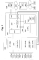
- Fig. 1 shows an exemplary schematic representation of a system with a data storage device according to an embodiment of the invention.
- the system comprises the data storage device 300, a machine tool 100, a control device 200 of the machine tool 100 and an optional external data processing device 400.
- the machine tool 100 comprises, for example, a plurality of actuators 110 of the machine tool 100 controllable by the control device 200 and a plurality of sensors 120 for outputting sensor signals relating to a machine state of the machine tool 100 to the control device 200.
- the actuators 110 can include, for example, drives for controllable linear and rotary axes (swivel and / or rotary axes) for a controlled relative movement between tool and workpiece, and also drives for tool-bearing work spindles (e.g. on milling machines) or workpiece-bearing work spindles (e.g. on lathes). .
- the actuators 110 can be electronically, hydraulically and / or pneumatically controlled valves, pumps or other supply devices for internal or external cooling lubricant supply or compressed air supply. Conveyor devices, pallet changers, workpiece changers, tool magazines and other machine tool accessories can also be controlled via drives or circuits or corresponding actuators.
- the sensors 120 can be, for example, sensors that can be assigned to the respective assemblies or components of the machine tool, for example the axes, the drives, axle bearings, the spindles, spindle bearings, a tool magazine, a tool changer, a pallet or workpiece changer, an internal or external cooling lubricant supply device , a chip conveyor, and / or a hydraulic and / or pneumatic control.
- sensors can be provided for the individual assemblies, for example position measuring sensors, current and / or voltage measuring sensors, temperature sensors, force sensors, acceleration sensors, vibration sensors, bearing diagnostic sensors, displacement sensors, level indicator sensors, liquid sensors (e.g. for measuring pH values in cooling lubricant liquids , Water content measuring sensors for oil, coolant etc.), water content sensors in pneumatic systems, and / or filter condition sensors.
- the available sensors on the machine tool and the availability of the sensor values on the control can turn out very differently depending on the machine and / or the control.
- the invention provides, by way of example, to specify in configuration data for reading out and processing the sensor data in a modifiable manner which sensors are available on the machine tool or are to be read out, and how the respective sensor values are read out (e.g. by specifying predetermined individual readout rates) and / or how the sensor values read out are to be processed and saved (processing rules).
- the data storage unit according to the invention can be used in a variety of ways and used on machines with extensive sensor packages with a large number of optional sensors, but can also be retrofitted on existing machines, in that the configuration data allow it, depending on the type and number of available sensors and control-dependent read-out options to configure the read-out function and further processing function of the data storage unit individually to the respective machine and its control or to adapt it to requirements, and yet to transfer the sensor data independently of the machine and control via a universal interface (e.g. OPC interface, or in particular OPC UA interface) to transmit further data processing devices.
- a universal interface e.g. OPC interface, or in particular OPC UA interface
- the configuration data can e.g. be stored in a configuration file in a universal data format in a markup language (e.g. as an XML file).
- a markup language e.g. as an XML file
- the control device 200 comprises, for example, a controller 210 with an NC controller 211 and a programmable logic controller 212 (also called a PLC or PLC for “Programmable Logic Control”).
- a controller 210 with an NC controller 211 and a programmable logic controller 212 (also called a PLC or PLC for “Programmable Logic Control”).
- control device 200 comprises, for example, a man-machine interface 220 (also called HMI for “human-machine interface”), with which it is possible for an operator of the machine tool 100 to control, monitor and / or control the machine tool 100 serve.
- the human-machine interface 220 comprises, for example, a graphical user interface 221 that can be displayed on a monitor or touchscreen (also called GUI for “Graphical User Interface”).
- the data storage device 300 comprises, for example, a first interface unit 310 (control interface), a readout unit 320, an example processor-controlled data processing unit 330, a second interface unit 340 (universal interface), and a data memory 350 with a first storage medium 360 and a second storage medium 370.
- the first storage medium 360 (for example a memory, RAM, a hard disk or a flash memory) stores, for example, configuration data 361 which, for example, specify a group of sensors 120 of the machine tool 100 as well as readout and processing rules for sensor signals of the group of sensors 120 of the machine tool 100
- the second storage medium 370 (for example one or more hard disks and / or flash memory) comprises, for example, a database 380 for storing sensor data 381 and certification data 382.
- the readout unit 320 is set up, for example, to read out sensor signal values of the sensor signals of the group of sensors 120 of the machine tool 110 specified in the configuration data via the first interface unit 310 from the control device 210 (e.g. from registers of the PLC 212), in particular, for example, on the basis of the information in FIG Configuration data specified readout rules.
- the data processing unit 330 is set up, for example, to process the sensor signal values read out by means of the readout unit into aggregated sensor data, in particular based on the processing rules specified in the configuration data, and to store the processed, aggregated sensor data 361 in the second storage medium 380 of the database 380.
- the second interface unit 340 is set up, for example, for data transmission with an external data processing device, via which the external data processing device can be granted access to sensor data 380 stored in the second storage medium 370.
- FIG. 1 An example of such external data processing devices is in Fig. 1 It is shown by way of example that the second interface unit 340 is connected to the man-machine interface 220 of the control device 200 such that, for example, an operator can receive or display sensor data 381 by means of an application 222 and the graphical user interface 221 of the man-machine interface 220 can access the sensor data 381 and / or view the configuration data 361 via the graphical user interface 221 or, if necessary, modify it, for example in order to change or view the readout and / or processing rules.
- the group of sensors 120 to be read out can also be viewed or changed.
- the second interface unit 340 is connected to a computer device 500 (e.g. an external PC, a notebook, a smartphone or a tablet) which comprises an application 502 and a web browser 501 that, for example, an operator can use the application 502 (e.g. a web application) and / or can get sensor data 381 displayed by means of the web browser 501 or can access the sensor data 381 and / or view the configuration data 361 or modify it if necessary, for example in order to apply the readout and / or processing rules change or view.
- the group of sensors 120 to be read out can also be viewed or changed.
- the first interface unit comprises, for example, a web service application 341 corresponding to the application 502 (which can grant access to the web applications as a service application or server application, for example the applications 222 and / or 502).
- FIG. 1 shown by way of example that the second interface unit 340 is connected via a local or global network 600 to a server 400 comprising a web service application 401 (for example analogous to the web service application 341).
- the server 400 can load or transfer sensor data 381 and also certification data 382 via the interface unit 340 and store them locally on the server 400 in a storage medium 402 (eg hard drives, flash memory, cloud storage, external storage arrays, etc.) (For example, in larger amounts of data if the storage medium 370 for storing the sensor data 381 comprises a ring buffer, and / or also for storing sensor data 381 from a plurality of machine tools 100, their Controllers 210 are each connected to a corresponding data storage device 300).
- a storage medium 402 eg hard drives, flash memory, cloud storage, external storage arrays, etc.
- a further server 400 and / or a further computer device 500 can be connected to the server 400 via a further local or global network 700 (e.g. a LAN, WAN, an intranet or the Internet).
- a further local or global network 700 e.g. a LAN, WAN, an intranet or the Internet.
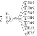
- Fig. 2 shows an exemplary schematic representation of a system according to a further exemplary embodiment of the invention.
- FIG. 2 a plurality of machine tools 100 with respective control devices 200 is shown by way of example, each of which is also analogous to FIG Fig. 1 are connected to a data storage device 300.
- respective external data processing devices 500 for example control PC, mini PC, PC, notebook, tablet, smartphone
- control PC mini PC
- PC Compact, tablet
- smartphone respective external data processing devices 500
- all data storage devices 300 are connected to a server 400 via a network 600 (e.g. a LAN, WAN, WLAN or intranet) in order to store sensor data read out, further processed and stored or temporarily stored in the respective data storage devices 300 on the controls 200 of the respective machine tools 100 381 (and / or certification data 382) to be transmitted repeatedly, regularly or on request to the server 400.
- a network 600 e.g. a LAN, WAN, WLAN or intranet
- the server 400 can thus store sensor data 381 collected by a plurality of machine tools 100 centrally on a server 400.
- a further network 700 for example a LAN, WAN, WLAN, intranet or the Internet, or alternatively via the same network 600
- further data processing devices 500 can access the data or sensor data 381 and / or certification data 382 collected and stored on the server 400 access in order to display and analyze them or to generate any maintenance or spare parts requirement forecasts.
- data from different machine tools 100 can also be compared in an analyzing manner.
- Fig. 3 shows an exemplary schematic representation of a system according to a further exemplary embodiment of the invention.
- a first group of a plurality of machine tools 100 with respective control devices 200 is shown by way of example, each of which is also analogous to FIG Fig. 1 are connected to a data storage device 300, and a second group of a plurality of machine tools 100 with respective control devices 200, which are also each analogous to Fig. 1 are connected to a data storage device 300.
- respective external data processing devices 500 are analogous to the data storage devices 300 Fig. 1 connected.
- all data storage devices 300 of the first group are connected to a first server 400 (first local server) via a first network 600 (for example a LAN, WAN, WLAN or intranet) in order to be able to access the respective data storage devices 300 on the controllers 200 of the respective To transmit machine tools 100 read out, further processed and stored or temporarily stored sensor data 381 (and / or certification data 382) repeatedly, regularly or on request to the first server 400.
- a first network 600 for example a LAN, WAN, WLAN or intranet
- the first server 400 can thus store sensor data 381 collected from a plurality of machine tools 100 of the first group in a locally centralized manner.
- a further network 700 e.g. a LAN, WAN, WLAN, intranet or the Internet, or alternatively via the same network 600
- the data can still be transmitted to a second server 400 (central server) and stored there in a globally centralized manner.
- all data storage devices 300 of the second group are connected to a third server 400 (second local server) via a second network 600 (e.g. a LAN, WAN, WLAN or intranet) in order to be able to access the respective data storage devices 300 on the controllers 200 of the respective Machine tools 100 to transmit read, further processed and stored or temporarily stored sensor data 381 (and / or certification data 382) repeatedly, regularly or on request to the third server 400 (central server).
- a third server 400 second local server
- a second network 600 e.g. a LAN, WAN, WLAN or intranet
- the third server 400 can thus store sensor data 381 collected from a plurality of machine tools 100 of the second group in a locally centralized manner.
- the further network 700 e.g. a LAN, WAN, WLAN, intranet or the Internet, or alternatively via the same network 600
- the data can still be transmitted to the second server 400 (central server) and stored there in a globally centralized manner.
- the second server 400 can thus store all sensor data or certification data of all machine tools of the first and second groups, and make them available for display or analysis, or also for comparison.
- the first and second groups can, for example, be machine tool groups that are set up in different factory halls or at different locations or at different companies.
- further data processing devices 500 can access the data or sensor data 381 and / or certification data 382 collected and stored on the second server 400 in order to display and analyze them or to generate any maintenance or replacement part requirement forecasts. In this case, data from different machine tools 100 can also be compared in an analyzing manner.
- an automatic ordering process can be triggered in exemplary embodiments, so that required maintenance items and / or spare parts are delivered to the location of the respective machine tool 100 or the corresponding delivery process is triggered automatically.
- the machine tool 100 or its connected human-machine interface 220 transmits instruction data which can be displayed via the graphical user interface 221 and indicate how the required maintenance and / or the required replacement part installation or the required replacement part replacement can be carried out on the machine tool 100.
- the instruction data can include text data and / or image data which specify instructions for one or more steps for maintenance and / or for installing spare parts or for replacing spare parts on machine tool 100.
- the instruction data can also include audio and / or video data that describe and / or show one or more steps for maintenance and / or for installing replacement parts or for replacing replacement parts on the machine tool 100.
- a data storage device for use on a numerically controlled machine tool or exemplary embodiments of a data storage device, which enables a simpler, clearer, easily further usable storage of sensor data of a numerically controlled machine tool, and which also reduces the data processing load of the control of the machine tool when reading out the sensor values is able to reduce and furthermore is able to reduce the amount of data to be stored while maintaining a high level of informative value, and which can also preferably be used universally independently of the machine tool type and / or control type.
Landscapes
- Engineering & Computer Science (AREA)
- Physics & Mathematics (AREA)
- General Physics & Mathematics (AREA)
- Automation & Control Theory (AREA)
- Human Computer Interaction (AREA)
- Manufacturing & Machinery (AREA)
- Numerical Control (AREA)
- General Factory Administration (AREA)
Claims (12)
- Dispositif de stockage de données (300) pour une machine-outil (100) à commande numérique, avec un système de commande (200) pour la commande d'une pluralité d'actionneurs (110) de la machine-outil (100) et une pluralité de capteurs (120) pour la délivrance de signaux de capteur concernant un état de machine de la machine-outil (100) au système de commande (200), dans lequel le dispositif de stockage de données (300) comprend :une première unité d'interface (310) pour la transmission de données avec le système de commande (200) numérique de la machine-outil (100),un premier support de stockage (360) pour le stockage de données de configuration (361), qui indiquent un groupe de capteurs de la machine-outil (100) ainsi que des règles de lecture et de traitement pour les signaux de capteur du groupe de capteurs de la machine-outil (100),une unité de lecture (320) pour la lecture de valeurs de signaux de capteur des signaux de capteur du groupe de capteurs de la machine-outil (100) indiqué dans les données de configuration (361) par l'intermédiaire de la première unité d'interface (310) sur la base des règles de lecture indiquées dans les données de configuration (361),une unité de traitement de données (330) pour le traitement des valeurs de signaux de capteur lues au moyen de l'unité de lecture (320) en données de détection (381) agrégées sur la base des règles de traitement indiquées dans les données de configuration (361),un deuxième support de stockage (370) pour le stockage des données de détection (381) agrégées, traitées par l'unité de traitement de données (330), etune deuxième unité d'interface (340) pour la transmission de données avec un système de traitement de données externe (220 ; 400 ; 500), par l'intermédiaire de laquelle l'accès aux données de détection (381) stockées dans le deuxième support de stockage (370) est accordé au système de traitement de données externe (220 ; 400 ; 500), dans lequella deuxième unité d'interface (340) est conçue pour transmettre les données de détection (381) stockées dans le deuxième support de stockage (370) à un serveur (400) par l'intermédiaire d'un réseau local ou mondial (600) ;la deuxième unité d'interface (340) est conçue pour accorder au système de traitement de données externe (220 ; 500) ou au serveur (400) l'accès aux données de configuration (361) stockées dans le premier support de stockage (360), pour la modification des données de configuration (361) ;la deuxième unité d'interface (340) est reliée à une interface homme-machine (220) du système de commande (200) de la machine-outil (100), pour la transmission des données de détection (381) stockées dans le deuxième support de stockage (370) et/ou des données de configuration (361) stockées dans le premier support de stockage (360) à l'interface homme-machine (220) pour être affichées sur une surface graphique de commande utilisateur (221) de l'interface homme-machine (220) du système de commande (200) de la machine-outil (100),lorsque le système de traitement de données externe (220 ; 500) ou le serveur (400) détermine ou prédit sur la base des données de détection (381) et/ou des données de configuration (361) qu'une maintenance est à effectuer sur la machine-outil (100), des données d'instructions sont transmises à l'interface homme-machine (220) et affichées par l'intermédiaire de la surface graphique de commande utilisateur (221).
- Dispositif de stockage de données (300) selon la revendication 1, caractérisé en ce que l'unité de traitement de données (330) est conçue pour compresser et/ou pour chiffrer les données de détection (381) stockées dans le deuxième support de stockage (370) pour la transmission de données au serveur (400).
- Dispositif de stockage de données (300) selon l'une quelconque des revendications précédentes, caractérisé en ce que la deuxième unité d'interface (340) comprend une interface web et/ou une application de service web, par l'intermédiaire desquelles l'accès aux données de détection (381) agrégées, stockées dans le deuxième support de stockage (370), peut être accordé au système de traitement de données externe au moyen d'un navigateur web et/ou d'une application web.
- Dispositif de stockage de données (300) selon l'une quelconque des revendications précédentes, caractérisé en ce que les données de configuration (361) indiquent en outre un format de données, et l'unité de traitement de données (330) est conçue pour stocker les données de détection (381) agrégées dans le format de données indiqué dans les données de configuration (361) dans le deuxième support de stockage (370).
- Dispositif de stockage de données (300) selon l'une quelconque des revendications précédentes, caractérisé en ce que le deuxième support de stockage (370) comprend une mémoire tampon circulaire et les données de détection (381) sont stockées dans la mémoire tampon circulaire.
- Dispositif de stockage de données (300) selon l'une quelconque des revendications précédentes, caractérisé en ce queles règles de lecture des données de configuration (361) pour un, plusieurs ou tous les signaux de capteur du groupe de capteurs (120) de la machine-outil (100) indiqué dans les données de configuration (361) indiquent une fréquence de lecture individuelle, etl'unité de lecture (320) est conçue, pour un signal de capteur correspondant, pour lire des valeurs de signaux de capteur avec la fréquence de lecture individuelle correspondante indiquée dans les données de configuration (361),dans lequel en particulier au moins une fréquence de lecture individuelle indiquée dans les données de configuration (361) est inférieure à une fréquence de stockage de valeurs de capteur d'un automate programmable industriel (212) et/ou à une fréquence de stockage de valeurs de capteur d'une commande numérique (211) du système de commande (200).
- Dispositif de stockage de données (300) selon l'une quelconque des revendications précédentes, caractérisé en ce queles règles de traitement des données de configuration (361) pour un, plusieurs ou tous les signaux de capteur du groupe de capteurs (120) de la machine-outil (100) indiqué dans les données de configuration (361) indiquent une règle de traitement individuelle, etl'unité de traitement de données (330) est conçue, pour un signal de capteur correspondant provenant d'une pluralité de valeurs de signaux de capteur lues pendant un laps de temps prédéfini dans la règle de traitement individuelle, pour calculer sur la base de la règle de traitement individuelle correspondante indiquée dans les données de configuration (361) une valeur de détection individuelle et pour la stocker dans le deuxième support de stockage (370),dans lequel en particulier la règle de traitement individuelle indique que la valeur de détection est à calculer comme valeur moyenne de la pluralité de valeurs de signaux de capteur lues pendant un laps de temps prédéfini dans la règle de traitement individuelle, ou la règle de traitement individuelle indique que la valeur de détection est à calculer comme valeur maximale ou valeur minimale de la pluralité de valeurs de signaux de capteur lues pendant un laps de temps prédéfini dans la règle de traitement individuelle.
- Dispositif de stockage de données (300) selon l'une quelconque des revendications précédentes, caractérisé en ce queles règles de traitement des données de configuration (361) pour au moins deux signaux de capteur du groupe de capteurs (120) de la machine-outil (100) indiqué dans les données de configuration (361) indiquent une règle de combinaison, etl'unité de traitement de données (330) est conçue, pour des valeurs de capteur des au moins deux signaux de capteur, pour calculer sur la base de la règle de combinaison une valeur de détection combinée et pour la stocker dans le deuxième support de stockage (370).
- Dispositif de stockage de données (300) selon l'une quelconque des revendications précédentes, caractérisé en ce queles données de configuration (361) pour un, plusieurs ou tous les signaux de capteur du groupe de capteurs (120) de la machine-outil indiqué dans les données de configuration comprennent des règles de certification, etl'unité de traitement de données (330) est conçue en outre, sur la base des règles de certification indiquées dans les données de configuration (361) et sur la base des signaux de capteur lus correspondants, pour générer des données de certification (382) et pour stocker les données de certification (382) générées dans le deuxième support de stockage (370)dans lequel l'accès aux données de certification (382) stockées dans le deuxième support de stockage (370) peut être accordé au système de traitement de données externe (220 ; 400 ; 500) par l'intermédiaire de la deuxième unité d'interface (340).
- Dispositif de stockage de données (300) selon l'une quelconque des revendications précédentes, caractérisé en ce queles données de configuration (361) pour un, plusieurs ou tous les signaux de capteur du groupe de capteurs (120) de la machine-outil indiqué dans les données de configuration indiquent une ou plusieurs valeurs limites individuelles, etl'unité de traitement de données (330) est conçue pour stocker dans le deuxième support de stockage les valeurs limites indiquées dans les données de configuration, faisant partie des valeurs de détection à calculer.
- Dispositif de stockage de données (300) selon l'une quelconque des revendications précédentes, caractérisé en ce quel'unité de lecture (320) est conçue en outre pour lire par l'intermédiaire de la première unité d'interface (310) des valeurs de relevé de compteur provenant de registres d'un automate programmable industriel du système de commande de la machine-outil, etl'unité de traitement de données (330) est conçue en outre pour stocker des valeurs de compteur lues conjointement avec une estampille temporelle dans les données de détection (381) dans le deuxième support de stockage (370).
- Système avec un dispositif de stockage de données (300) selon l'une quelconque des revendications précédentes et un système de traitement de données externe (220 ; 400 ; 500), qui est relié à la deuxième unité d'interface (340) par l'intermédiaire d'un réseau local ou mondial (600) et est conçu pour avoir accès aux données de détection (381) stockées dans le deuxième support de stockage (370) et/ou aux données de configuration (361) stockées dans le premier support de stockage (360) par l'intermédiaire de la deuxième unité d'interface (340).
Applications Claiming Priority (3)
| Application Number | Priority Date | Filing Date | Title |
|---|---|---|---|
| DE102016203554 | 2016-03-03 | ||
| DE102016217443.6A DE102016217443A1 (de) | 2016-03-03 | 2016-09-13 | Datenspeichervorrichtung zum Einsatz an einer numerisch gesteuerten Werkzeugmaschine |
| PCT/EP2017/055065 WO2017149145A1 (fr) | 2016-03-03 | 2017-03-03 | Dispositif de stockage de données à mettre en œuvre sur une machine-outil à commande numérique |
Publications (2)
| Publication Number | Publication Date |
|---|---|
| EP3423909A1 EP3423909A1 (fr) | 2019-01-09 |
| EP3423909B1 true EP3423909B1 (fr) | 2021-11-03 |
Family
ID=59650836
Family Applications (1)
| Application Number | Title | Priority Date | Filing Date |
|---|---|---|---|
| EP17716462.1A Active EP3423909B1 (fr) | 2016-03-03 | 2017-03-03 | Dispositif de stockage de données à mettre en oeuvre sur une machine-outil à commande numérique |
Country Status (8)
| Country | Link |
|---|---|
| US (1) | US20190302731A1 (fr) |
| EP (1) | EP3423909B1 (fr) |
| JP (1) | JP6730441B2 (fr) |
| KR (1) | KR20180127383A (fr) |
| CN (1) | CN109313438A (fr) |
| DE (1) | DE102016217443A1 (fr) |
| ES (1) | ES2903262T3 (fr) |
| WO (1) | WO2017149145A1 (fr) |
Families Citing this family (8)
| Publication number | Priority date | Publication date | Assignee | Title |
|---|---|---|---|---|
| JP6392843B2 (ja) | 2016-12-28 | 2018-09-19 | ファナック株式会社 | 工作機械、生産管理システム及び工具の寿命を予測・検出する方法 |
| US11221616B2 (en) * | 2017-06-27 | 2022-01-11 | Schneider Electric Systems Usa, Inc. | Sensor service prediction |
| JP6813521B2 (ja) * | 2018-02-08 | 2021-01-13 | ファナック株式会社 | 温度計測装置 |
| JP6744557B2 (ja) * | 2018-09-14 | 2020-08-19 | 株式会社安川電機 | 動作データ収集システム、動作データ収集方法、及びプログラム |
| DE102019106976B4 (de) * | 2019-03-19 | 2021-04-22 | Argo-Hytos Group Ag | Filterdeckel, Filtereinrichtung, Filtersystem und Verfahren zur Berechnung der Reststandzeit eines Filterelements |
| EP3723346A1 (fr) * | 2019-04-10 | 2020-10-14 | ABB Schweiz AG | Agrégation d'espace d'adresse sélective |
| CN112230603B (zh) * | 2020-10-14 | 2021-08-13 | 深圳吉兰丁智能科技有限公司 | 一种基于数控机床的多传感器数据采集方法及系统 |
| DE102020213966A1 (de) | 2020-11-06 | 2022-06-02 | Trumpf Werkzeugmaschinen Gmbh + Co. Kg | Mobile Kommunikationseinrichtung und mit der mobilen Kommunikationseinrichtung kontrollierbare Werkzeugmaschine |
Citations (1)
| Publication number | Priority date | Publication date | Assignee | Title |
|---|---|---|---|---|
| DE102013005769A1 (de) * | 2013-04-05 | 2014-10-09 | Robert Bosch Gmbh | Maschine, Computerprogrammprodukt für ein Gerät zur Anzeige von Daten und Verfahren zur Statusüberwachung einer Maschine |
Family Cites Families (13)
| Publication number | Priority date | Publication date | Assignee | Title |
|---|---|---|---|---|
| US5038318A (en) * | 1987-12-17 | 1991-08-06 | Square D Company | Device for communicating real time data between a programmable logic controller and a program operating in a central controller |
| JP2002132321A (ja) * | 2000-10-20 | 2002-05-10 | Susumu Ueno | 工作機械の保守システム及び保守方法 |
| US7222048B2 (en) * | 2005-04-21 | 2007-05-22 | General Electric Company | Methods and systems for diagnosing machinery |
| US7933666B2 (en) * | 2006-11-10 | 2011-04-26 | Rockwell Automation Technologies, Inc. | Adjustable data collection rate for embedded historians |
| DE102009024101A1 (de) * | 2009-04-17 | 2010-10-21 | Robert Bosch Gmbh | Verfahren zum Aufbereiten von Prozesszustandsdaten und/oder Maschinenzustandsdaten einer Werkzeugmaschine |
| CN103810124A (zh) * | 2012-11-09 | 2014-05-21 | 辉达公司 | 用于数据传输的系统及方法 |
| US10204178B2 (en) * | 2013-02-04 | 2019-02-12 | Authentise Inc. | System, method, and program product for digital production management |
| JP5993776B2 (ja) * | 2013-03-29 | 2016-09-14 | 株式会社日立製作所 | データ伝送システム及び受信装置 |
| US10108179B2 (en) * | 2013-04-10 | 2018-10-23 | Mitsubishi Electric Corporation | Numerical control device, information coordination system, and information coordination program |
| CN103792910B (zh) * | 2013-12-02 | 2016-08-24 | 上海交通大学 | 一种数控机床的网络群控式误差动态补偿系统 |
| WO2015114821A1 (fr) * | 2014-01-31 | 2015-08-06 | 三菱電機株式会社 | Système de commande de surveillance et appareil de commande |
| CN104536423A (zh) * | 2015-01-04 | 2015-04-22 | 北京数码大方科技股份有限公司 | 数控机床的生产辅助装置和生产数据传输方法 |
| US10118296B1 (en) * | 2015-09-10 | 2018-11-06 | X Development Llc | Tagged robot sensor data |
-
2016
- 2016-09-13 DE DE102016217443.6A patent/DE102016217443A1/de not_active Withdrawn
-
2017
- 2017-03-03 KR KR1020187028472A patent/KR20180127383A/ko active Search and Examination
- 2017-03-03 EP EP17716462.1A patent/EP3423909B1/fr active Active
- 2017-03-03 US US16/082,053 patent/US20190302731A1/en not_active Abandoned
- 2017-03-03 JP JP2018546476A patent/JP6730441B2/ja active Active
- 2017-03-03 ES ES17716462T patent/ES2903262T3/es active Active
- 2017-03-03 WO PCT/EP2017/055065 patent/WO2017149145A1/fr active Application Filing
- 2017-03-03 CN CN201780015058.5A patent/CN109313438A/zh active Pending
Patent Citations (1)
| Publication number | Priority date | Publication date | Assignee | Title |
|---|---|---|---|---|
| DE102013005769A1 (de) * | 2013-04-05 | 2014-10-09 | Robert Bosch Gmbh | Maschine, Computerprogrammprodukt für ein Gerät zur Anzeige von Daten und Verfahren zur Statusüberwachung einer Maschine |
Also Published As
| Publication number | Publication date |
|---|---|
| WO2017149145A1 (fr) | 2017-09-08 |
| DE102016217443A1 (de) | 2017-09-07 |
| US20190302731A1 (en) | 2019-10-03 |
| JP6730441B2 (ja) | 2020-07-29 |
| ES2903262T3 (es) | 2022-03-31 |
| EP3423909A1 (fr) | 2019-01-09 |
| JP2019507931A (ja) | 2019-03-22 |
| CN109313438A (zh) | 2019-02-05 |
| KR20180127383A (ko) | 2018-11-28 |
Similar Documents
| Publication | Publication Date | Title |
|---|---|---|
| EP3423909B1 (fr) | Dispositif de stockage de données à mettre en oeuvre sur une machine-outil à commande numérique | |
| EP3519903B1 (fr) | Dispositif d'interface de données à utiliser dans une machine-outil à commande numérique | |
| DE112015004984T5 (de) | Client-Vorrichtung zur Datenerfassung und Vorverarbeitung von prozessbezogenen Massendaten von mindestens einer CNC-Maschine oder einem Industrieroboter | |
| DE102009045386A1 (de) | Verfahren zum Betreiben eines Feldbus-Interface | |
| EP2419799A1 (fr) | Procédé de préparation de données d'état de processus et/ou de données d'état de machine d'une machine-outil | |
| DE102008027935A1 (de) | Vorrichtung zur Integration von Geräteobjekten in eine übergeordnete Steuereinheit | |
| EP2042956A2 (fr) | Interface entre un système de gestion de la fabrication et un système d'automatisation | |
| EP3335085B1 (fr) | Systeme de commande et procede de fonctionnement d'un systeme de commande dote d'une commande reelle et virtuelle | |
| DE10326427A1 (de) | Verfahren und Vorrichtung zur Ermittlung der Ursachen von Störungen in industriellen Prozessen | |
| EP2808749B1 (fr) | Procédé d'échange d'informations de commande entre des appareils de commande et d'observation d'un système d'automatisation industriel et système d'automatisation industriel | |
| DE102008061721A1 (de) | Administrationssystem | |
| WO2010046248A1 (fr) | Procédé pour l'adaptation dynamique d'un système de diagnostic | |
| EP3861413B1 (fr) | Procédé pour établir une communication de réseau par opc ua | |
| EP3384353B1 (fr) | Procédé et système d'optimisation de la commande d'au moins un appareil de champ d'une pluralité d'appareils de champ du secteur de la robotique | |
| EP2419798A1 (fr) | Procédé permettant d'obtenir une information concernant l'usure d'un composant d'une machine et procédé de préparation d'un algorithme alternatif | |
| DE102017123225A1 (de) | Smartwatch und Verfahren Instandhaltung einer Anlage der Automatisierungstechnik | |
| WO2003060617A1 (fr) | Procede et dispositif pour detecter et traiter des signaux issus de processus industriels | |
| DE102009000052A1 (de) | Verfahren zur Integration von Geräteobjekten in ein objektbasiertes Managementsystem für Feldgeräte in der Automatisierungstechnik | |
| EP3770704A1 (fr) | Système d'automatisation décentralisée en nuage | |
| EP2159658A1 (fr) | Procédé et contrôleur d'automatisation destinés à l'émission d'une information de maintenance d'un composant d'automatisation | |
| DE102018130649A1 (de) | Verfahren zum Analysieren des Messverhaltens eines Feldgeräts der Automatisierungstechnik in Abhängigkeit der Parametrierung des Feldgeräts | |
| DE102013212181A1 (de) | Schweissanlage und Verfahren zum Austauschen von Prozessdaten einer Schweissanlage | |
| EP3712724A1 (fr) | Agencement d'automatisation, procédé de fonctionnement de l'agencement d'automatisation ainsi que programme informatique | |
| DE102020111806A1 (de) | Verfahren zum Instandhalten einer Anlage der Automatisierungstechnik | |
| DE102018132288A1 (de) | Verfahren zum Integrieren einer Feldzugriffseinheit in ein Kommunikationsnetzwerk der Automatisierungstechnik |
Legal Events
| Date | Code | Title | Description |
|---|---|---|---|
| STAA | Information on the status of an ep patent application or granted ep patent |
Free format text: STATUS: UNKNOWN |
|
| STAA | Information on the status of an ep patent application or granted ep patent |
Free format text: STATUS: THE INTERNATIONAL PUBLICATION HAS BEEN MADE |
|
| PUAI | Public reference made under article 153(3) epc to a published international application that has entered the european phase |
Free format text: ORIGINAL CODE: 0009012 |
|
| STAA | Information on the status of an ep patent application or granted ep patent |
Free format text: STATUS: REQUEST FOR EXAMINATION WAS MADE |
|
| 17P | Request for examination filed |
Effective date: 20181004 |
|
| AK | Designated contracting states |
Kind code of ref document: A1 Designated state(s): AL AT BE BG CH CY CZ DE DK EE ES FI FR GB GR HR HU IE IS IT LI LT LU LV MC MK MT NL NO PL PT RO RS SE SI SK SM TR |
|
| AX | Request for extension of the european patent |
Extension state: BA ME |
|
| DAV | Request for validation of the european patent (deleted) | ||
| DAX | Request for extension of the european patent (deleted) | ||
| STAA | Information on the status of an ep patent application or granted ep patent |
Free format text: STATUS: EXAMINATION IS IN PROGRESS |
|
| 17Q | First examination report despatched |
Effective date: 20201015 |
|
| GRAP | Despatch of communication of intention to grant a patent |
Free format text: ORIGINAL CODE: EPIDOSNIGR1 |
|
| STAA | Information on the status of an ep patent application or granted ep patent |
Free format text: STATUS: GRANT OF PATENT IS INTENDED |
|
| INTG | Intention to grant announced |
Effective date: 20210604 |
|
| GRAS | Grant fee paid |
Free format text: ORIGINAL CODE: EPIDOSNIGR3 |
|
| GRAA | (expected) grant |
Free format text: ORIGINAL CODE: 0009210 |
|
| STAA | Information on the status of an ep patent application or granted ep patent |
Free format text: STATUS: THE PATENT HAS BEEN GRANTED |
|
| AK | Designated contracting states |
Kind code of ref document: B1 Designated state(s): AL AT BE BG CH CY CZ DE DK EE ES FI FR GB GR HR HU IE IS IT LI LT LU LV MC MK MT NL NO PL PT RO RS SE SI SK SM TR |
|
| REG | Reference to a national code |
Ref country code: GB Ref legal event code: FG4D Free format text: NOT ENGLISH |
|
| REG | Reference to a national code |
Ref country code: AT Ref legal event code: REF Ref document number: 1444534 Country of ref document: AT Kind code of ref document: T Effective date: 20211115 Ref country code: CH Ref legal event code: EP |
|
| REG | Reference to a national code |
Ref country code: DE Ref legal event code: R096 Ref document number: 502017011907 Country of ref document: DE |
|
| REG | Reference to a national code |
Ref country code: IE Ref legal event code: FG4D Free format text: LANGUAGE OF EP DOCUMENT: GERMAN |
|
| REG | Reference to a national code |
Ref country code: LT Ref legal event code: MG9D |
|
| REG | Reference to a national code |
Ref country code: NL Ref legal event code: MP Effective date: 20211103 |
|
| REG | Reference to a national code |
Ref country code: ES Ref legal event code: FG2A Ref document number: 2903262 Country of ref document: ES Kind code of ref document: T3 Effective date: 20220331 |
|
| PG25 | Lapsed in a contracting state [announced via postgrant information from national office to epo] |
Ref country code: RS Free format text: LAPSE BECAUSE OF FAILURE TO SUBMIT A TRANSLATION OF THE DESCRIPTION OR TO PAY THE FEE WITHIN THE PRESCRIBED TIME-LIMIT Effective date: 20211103 Ref country code: LT Free format text: LAPSE BECAUSE OF FAILURE TO SUBMIT A TRANSLATION OF THE DESCRIPTION OR TO PAY THE FEE WITHIN THE PRESCRIBED TIME-LIMIT Effective date: 20211103 Ref country code: FI Free format text: LAPSE BECAUSE OF FAILURE TO SUBMIT A TRANSLATION OF THE DESCRIPTION OR TO PAY THE FEE WITHIN THE PRESCRIBED TIME-LIMIT Effective date: 20211103 Ref country code: BG Free format text: LAPSE BECAUSE OF FAILURE TO SUBMIT A TRANSLATION OF THE DESCRIPTION OR TO PAY THE FEE WITHIN THE PRESCRIBED TIME-LIMIT Effective date: 20220203 |
|
| PG25 | Lapsed in a contracting state [announced via postgrant information from national office to epo] |
Ref country code: IS Free format text: LAPSE BECAUSE OF FAILURE TO SUBMIT A TRANSLATION OF THE DESCRIPTION OR TO PAY THE FEE WITHIN THE PRESCRIBED TIME-LIMIT Effective date: 20220303 Ref country code: SE Free format text: LAPSE BECAUSE OF FAILURE TO SUBMIT A TRANSLATION OF THE DESCRIPTION OR TO PAY THE FEE WITHIN THE PRESCRIBED TIME-LIMIT Effective date: 20211103 Ref country code: PT Free format text: LAPSE BECAUSE OF FAILURE TO SUBMIT A TRANSLATION OF THE DESCRIPTION OR TO PAY THE FEE WITHIN THE PRESCRIBED TIME-LIMIT Effective date: 20220303 Ref country code: PL Free format text: LAPSE BECAUSE OF FAILURE TO SUBMIT A TRANSLATION OF THE DESCRIPTION OR TO PAY THE FEE WITHIN THE PRESCRIBED TIME-LIMIT Effective date: 20211103 Ref country code: NO Free format text: LAPSE BECAUSE OF FAILURE TO SUBMIT A TRANSLATION OF THE DESCRIPTION OR TO PAY THE FEE WITHIN THE PRESCRIBED TIME-LIMIT Effective date: 20220203 Ref country code: NL Free format text: LAPSE BECAUSE OF FAILURE TO SUBMIT A TRANSLATION OF THE DESCRIPTION OR TO PAY THE FEE WITHIN THE PRESCRIBED TIME-LIMIT Effective date: 20211103 Ref country code: LV Free format text: LAPSE BECAUSE OF FAILURE TO SUBMIT A TRANSLATION OF THE DESCRIPTION OR TO PAY THE FEE WITHIN THE PRESCRIBED TIME-LIMIT Effective date: 20211103 Ref country code: HR Free format text: LAPSE BECAUSE OF FAILURE TO SUBMIT A TRANSLATION OF THE DESCRIPTION OR TO PAY THE FEE WITHIN THE PRESCRIBED TIME-LIMIT Effective date: 20211103 Ref country code: GR Free format text: LAPSE BECAUSE OF FAILURE TO SUBMIT A TRANSLATION OF THE DESCRIPTION OR TO PAY THE FEE WITHIN THE PRESCRIBED TIME-LIMIT Effective date: 20220204 |
|
| PG25 | Lapsed in a contracting state [announced via postgrant information from national office to epo] |
Ref country code: SM Free format text: LAPSE BECAUSE OF FAILURE TO SUBMIT A TRANSLATION OF THE DESCRIPTION OR TO PAY THE FEE WITHIN THE PRESCRIBED TIME-LIMIT Effective date: 20211103 Ref country code: SK Free format text: LAPSE BECAUSE OF FAILURE TO SUBMIT A TRANSLATION OF THE DESCRIPTION OR TO PAY THE FEE WITHIN THE PRESCRIBED TIME-LIMIT Effective date: 20211103 Ref country code: RO Free format text: LAPSE BECAUSE OF FAILURE TO SUBMIT A TRANSLATION OF THE DESCRIPTION OR TO PAY THE FEE WITHIN THE PRESCRIBED TIME-LIMIT Effective date: 20211103 Ref country code: EE Free format text: LAPSE BECAUSE OF FAILURE TO SUBMIT A TRANSLATION OF THE DESCRIPTION OR TO PAY THE FEE WITHIN THE PRESCRIBED TIME-LIMIT Effective date: 20211103 Ref country code: DK Free format text: LAPSE BECAUSE OF FAILURE TO SUBMIT A TRANSLATION OF THE DESCRIPTION OR TO PAY THE FEE WITHIN THE PRESCRIBED TIME-LIMIT Effective date: 20211103 Ref country code: CZ Free format text: LAPSE BECAUSE OF FAILURE TO SUBMIT A TRANSLATION OF THE DESCRIPTION OR TO PAY THE FEE WITHIN THE PRESCRIBED TIME-LIMIT Effective date: 20211103 |
|
| REG | Reference to a national code |
Ref country code: DE Ref legal event code: R097 Ref document number: 502017011907 Country of ref document: DE |
|
| PLBE | No opposition filed within time limit |
Free format text: ORIGINAL CODE: 0009261 |
|
| STAA | Information on the status of an ep patent application or granted ep patent |
Free format text: STATUS: NO OPPOSITION FILED WITHIN TIME LIMIT |
|
| 26N | No opposition filed |
Effective date: 20220804 |
|
| PG25 | Lapsed in a contracting state [announced via postgrant information from national office to epo] |
Ref country code: MC Free format text: LAPSE BECAUSE OF FAILURE TO SUBMIT A TRANSLATION OF THE DESCRIPTION OR TO PAY THE FEE WITHIN THE PRESCRIBED TIME-LIMIT Effective date: 20211103 Ref country code: AL Free format text: LAPSE BECAUSE OF FAILURE TO SUBMIT A TRANSLATION OF THE DESCRIPTION OR TO PAY THE FEE WITHIN THE PRESCRIBED TIME-LIMIT Effective date: 20211103 |
|
| PG25 | Lapsed in a contracting state [announced via postgrant information from national office to epo] |
Ref country code: SI Free format text: LAPSE BECAUSE OF FAILURE TO SUBMIT A TRANSLATION OF THE DESCRIPTION OR TO PAY THE FEE WITHIN THE PRESCRIBED TIME-LIMIT Effective date: 20211103 |
|
| REG | Reference to a national code |
Ref country code: BE Ref legal event code: MM Effective date: 20220331 |
|
| PG25 | Lapsed in a contracting state [announced via postgrant information from national office to epo] |
Ref country code: LU Free format text: LAPSE BECAUSE OF NON-PAYMENT OF DUE FEES Effective date: 20220303 Ref country code: IE Free format text: LAPSE BECAUSE OF NON-PAYMENT OF DUE FEES Effective date: 20220303 |
|
| PG25 | Lapsed in a contracting state [announced via postgrant information from national office to epo] |
Ref country code: BE Free format text: LAPSE BECAUSE OF NON-PAYMENT OF DUE FEES Effective date: 20220331 |
|
| PGFP | Annual fee paid to national office [announced via postgrant information from national office to epo] |
Ref country code: FR Payment date: 20230320 Year of fee payment: 7 |
|
| REG | Reference to a national code |
Ref country code: AT Ref legal event code: MM01 Ref document number: 1444534 Country of ref document: AT Kind code of ref document: T Effective date: 20220303 |
|
| PG25 | Lapsed in a contracting state [announced via postgrant information from national office to epo] |
Ref country code: AT Free format text: LAPSE BECAUSE OF NON-PAYMENT OF DUE FEES Effective date: 20220303 |
|
| PGFP | Annual fee paid to national office [announced via postgrant information from national office to epo] |
Ref country code: IT Payment date: 20230331 Year of fee payment: 7 Ref country code: ES Payment date: 20230414 Year of fee payment: 7 Ref country code: CH Payment date: 20230402 Year of fee payment: 7 |
|
| PG25 | Lapsed in a contracting state [announced via postgrant information from national office to epo] |
Ref country code: HU Free format text: LAPSE BECAUSE OF FAILURE TO SUBMIT A TRANSLATION OF THE DESCRIPTION OR TO PAY THE FEE WITHIN THE PRESCRIBED TIME-LIMIT; INVALID AB INITIO Effective date: 20170303 |
|
| PG25 | Lapsed in a contracting state [announced via postgrant information from national office to epo] |
Ref country code: MK Free format text: LAPSE BECAUSE OF FAILURE TO SUBMIT A TRANSLATION OF THE DESCRIPTION OR TO PAY THE FEE WITHIN THE PRESCRIBED TIME-LIMIT Effective date: 20211103 Ref country code: CY Free format text: LAPSE BECAUSE OF FAILURE TO SUBMIT A TRANSLATION OF THE DESCRIPTION OR TO PAY THE FEE WITHIN THE PRESCRIBED TIME-LIMIT Effective date: 20211103 |
|
| PGFP | Annual fee paid to national office [announced via postgrant information from national office to epo] |
Ref country code: DE Payment date: 20240331 Year of fee payment: 8 Ref country code: GB Payment date: 20240322 Year of fee payment: 8 |