EP3423309B1 - Dicht- und blendleiste für die b-säule eines personenkraftwagens - Google Patents
Dicht- und blendleiste für die b-säule eines personenkraftwagens Download PDFInfo
- Publication number
- EP3423309B1 EP3423309B1 EP17700825.7A EP17700825A EP3423309B1 EP 3423309 B1 EP3423309 B1 EP 3423309B1 EP 17700825 A EP17700825 A EP 17700825A EP 3423309 B1 EP3423309 B1 EP 3423309B1
- Authority
- EP
- European Patent Office
- Prior art keywords
- sealing
- cover
- pillar
- support
- decorative
- Prior art date
- Legal status (The legal status is an assumption and is not a legal conclusion. Google has not performed a legal analysis and makes no representation as to the accuracy of the status listed.)
- Active
Links
Images


Classifications
-
- B—PERFORMING OPERATIONS; TRANSPORTING
- B60—VEHICLES IN GENERAL
- B60J—WINDOWS, WINDSCREENS, NON-FIXED ROOFS, DOORS, OR SIMILAR DEVICES FOR VEHICLES; REMOVABLE EXTERNAL PROTECTIVE COVERINGS SPECIALLY ADAPTED FOR VEHICLES
- B60J10/00—Sealing arrangements
- B60J10/70—Sealing arrangements specially adapted for windows or windscreens
- B60J10/74—Sealing arrangements specially adapted for windows or windscreens for sliding window panes, e.g. sash guides
- B60J10/77—Sealing arrangements specially adapted for windows or windscreens for sliding window panes, e.g. sash guides for sashless windows, i.e. for frameless windows forming a seal directly with the vehicle body
- B60J10/777—Sealing arrangements specially adapted for windows or windscreens for sliding window panes, e.g. sash guides for sashless windows, i.e. for frameless windows forming a seal directly with the vehicle body the sealing arrangement being between the edges of adjacent panes
- B60J10/7775—Sealing arrangements specially adapted for windows or windscreens for sliding window panes, e.g. sash guides for sashless windows, i.e. for frameless windows forming a seal directly with the vehicle body the sealing arrangement being between the edges of adjacent panes mounted on the pillar
-
- B—PERFORMING OPERATIONS; TRANSPORTING
- B60—VEHICLES IN GENERAL
- B60R—VEHICLES, VEHICLE FITTINGS, OR VEHICLE PARTS, NOT OTHERWISE PROVIDED FOR
- B60R13/00—Elements for body-finishing, identifying, or decorating; Arrangements or adaptations for advertising purposes
- B60R13/04—External Ornamental or guard strips; Ornamental inscriptive devices thereon
-
- B—PERFORMING OPERATIONS; TRANSPORTING
- B29—WORKING OF PLASTICS; WORKING OF SUBSTANCES IN A PLASTIC STATE IN GENERAL
- B29C—SHAPING OR JOINING OF PLASTICS; SHAPING OF MATERIAL IN A PLASTIC STATE, NOT OTHERWISE PROVIDED FOR; AFTER-TREATMENT OF THE SHAPED PRODUCTS, e.g. REPAIRING
- B29C45/00—Injection moulding, i.e. forcing the required volume of moulding material through a nozzle into a closed mould; Apparatus therefor
- B29C45/14—Injection moulding, i.e. forcing the required volume of moulding material through a nozzle into a closed mould; Apparatus therefor incorporating preformed parts or layers, e.g. injection moulding around inserts or for coating articles
-
- B—PERFORMING OPERATIONS; TRANSPORTING
- B60—VEHICLES IN GENERAL
- B60J—WINDOWS, WINDSCREENS, NON-FIXED ROOFS, DOORS, OR SIMILAR DEVICES FOR VEHICLES; REMOVABLE EXTERNAL PROTECTIVE COVERINGS SPECIALLY ADAPTED FOR VEHICLES
- B60J10/00—Sealing arrangements
- B60J10/45—Assembling sealing arrangements with vehicle parts
-
- B—PERFORMING OPERATIONS; TRANSPORTING
- B60—VEHICLES IN GENERAL
- B60J—WINDOWS, WINDSCREENS, NON-FIXED ROOFS, DOORS, OR SIMILAR DEVICES FOR VEHICLES; REMOVABLE EXTERNAL PROTECTIVE COVERINGS SPECIALLY ADAPTED FOR VEHICLES
- B60J10/00—Sealing arrangements
- B60J10/70—Sealing arrangements specially adapted for windows or windscreens
- B60J10/74—Sealing arrangements specially adapted for windows or windscreens for sliding window panes, e.g. sash guides
- B60J10/77—Sealing arrangements specially adapted for windows or windscreens for sliding window panes, e.g. sash guides for sashless windows, i.e. for frameless windows forming a seal directly with the vehicle body
-
- B—PERFORMING OPERATIONS; TRANSPORTING
- B60—VEHICLES IN GENERAL
- B60J—WINDOWS, WINDSCREENS, NON-FIXED ROOFS, DOORS, OR SIMILAR DEVICES FOR VEHICLES; REMOVABLE EXTERNAL PROTECTIVE COVERINGS SPECIALLY ADAPTED FOR VEHICLES
- B60J10/00—Sealing arrangements
- B60J10/70—Sealing arrangements specially adapted for windows or windscreens
- B60J10/74—Sealing arrangements specially adapted for windows or windscreens for sliding window panes, e.g. sash guides
- B60J10/79—Sealing arrangements specially adapted for windows or windscreens for sliding window panes, e.g. sash guides for flush-glass windows, i.e. for windows flush with the vehicle body or the window frame
-
- B—PERFORMING OPERATIONS; TRANSPORTING
- B29—WORKING OF PLASTICS; WORKING OF SUBSTANCES IN A PLASTIC STATE IN GENERAL
- B29L—INDEXING SCHEME ASSOCIATED WITH SUBCLASS B29C, RELATING TO PARTICULAR ARTICLES
- B29L2031/00—Other particular articles
- B29L2031/30—Vehicles, e.g. ships or aircraft, or body parts thereof
- B29L2031/3005—Body finishings
- B29L2031/302—Trim strips
-
- B—PERFORMING OPERATIONS; TRANSPORTING
- B29—WORKING OF PLASTICS; WORKING OF SUBSTANCES IN A PLASTIC STATE IN GENERAL
- B29L—INDEXING SCHEME ASSOCIATED WITH SUBCLASS B29C, RELATING TO PARTICULAR ARTICLES
- B29L2031/00—Other particular articles
- B29L2031/30—Vehicles, e.g. ships or aircraft, or body parts thereof
- B29L2031/3055—Cars
-
- B—PERFORMING OPERATIONS; TRANSPORTING
- B60—VEHICLES IN GENERAL
- B60Y—INDEXING SCHEME RELATING TO ASPECTS CROSS-CUTTING VEHICLE TECHNOLOGY
- B60Y2200/00—Type of vehicle
- B60Y2200/10—Road Vehicles
- B60Y2200/11—Passenger cars; Automobiles
Definitions
- the invention relates to a sealing and cover strip for the B-pillar of a two- or four-door passenger car with frameless doors.
- the B-pillar of a passenger car is arranged between the front door and the rear door of a car, or in the case of a coupe between the front door side window and the rear movable or fixed side glazing of a passenger car.
- the seals are attached directly to the B-pillar.
- the B-pillar usually has a support panel and a decorative panel which together form a groove on the longitudinal side that is assigned to a retractable side window, into which a sealing profile is clipped or drawn.
- a sealing strip is for example from the DE 10 2004 041 741 B3 known.
- the seal itself consists of two profiles and three vulcanized molded corners.
- the DE 203 04 269 U1 a sealing strip for a vehicle, which comprises two molded parts which form a U-shaped space between them for receiving a side window of the vehicle.
- a sealing element is molded onto each of the molded parts.
- the molded parts are each attached to the frame structure of the vehicle.
- the EP 2 113 422 A1 discloses a trim part for the B-pillar of a motor vehicle with a support part and a design part.
- the design part comprises a visible surface on its side facing outwards in the installed state.
- the carrier part comprises a glass guide channel running along its longitudinal direction into which a seal can be locked.
- GB 2 247 489 A describes a decorative service for covering a B-pillar of a car.
- the trim strip is attached to a flange of the B-pillar on one of its long sides.
- a seal for sealing a retractable side window is attached to the other long side of the trim strip.
- the cover now consists of two halves.
- the decorative panel including the molded seal and the carrier panel with the molded seal are combined to form one component.
- the seal is no longer clipped into the groove formed between the support panel and the decorative panel; the seal is rather divided into two halves, one half being connected to the decorative panel and the other half being connected to the carrier panel.
- the two halves form a sealing profile which was previously made in one piece.
- the respective seal halves of the seal can be connected to the decorative panel and the carrier panel by two-component injection molding.
- one of the mold halves only has to be exchanged during the injection molding process in order to then inject the second component, here the elastomer material for the seal.
- the side of the one seal half facing the visible surface of the decorative panel merges into the visible surface of the decorative panel in a gap-free, flush manner.
- An advantageous variant of the invention provides that seals are provided on both longitudinal sides and on the underside of the carrier panel and decorative panel. In this way, the pane of the rear vehicle door can also be designed without a frame.
- the assembly effort can be further reduced if corner pieces are provided at the upper end of the support panel, which merge into the window frame on the roof rail of the passenger car, the end pieces also being produced by two-component injection molding distributed over the support panel and decorative panel.
- the sealing halves can have end pieces at the lower end which are injection molded in one piece with the cover parts. All sealing elements as well as end and corner pieces are connected to a total of two parts.
- both parts that is to say the decorative panel and the carrier panel, can be connected to one another in a materially bonded manner, for example by ultrasonic welding.
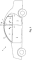
- the in Fig. 1 The passenger car shown is a vehicle which has a frameless pane 4 or 5 both in the area of the front door 2 and in the area of the rear door 3. In the area of the roof spar 6 and the door shafts, the panes 4 and 5 are sealed by pane frames known per se. In the area of the B-pillar 7, a sealing and cover strip 8 is provided for this purpose, which is shown in FIG Fig. 2 is shown in more detail.
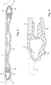
- the sealing and fascia strip 8 when looking at the Fig. 3 , from an outer decorative panel 9, which faces the outside of the vehicle, and an underlying support panel 10, with which the sealing and cover strip 8 is attached to the B-pillar of the vehicle.
- sealing profiles 11 and 12 are provided for the side windows 4 and 5.
- These sealing profiles 11 and 12 each consist of two sealing halves 13 and 14 or 13 'and 14', one half 13 or 13 'of which is connected to the decorative panel and the other half 14 or 14' is connected to the carrier panel 10 .
- corner pieces 16 and 17 are provided, which form the transition from the sealing and facing strip 8 to the pane surround 6 on the upper roof spar.
- corner pieces 16 and 17, like the sealing halves 14 and 14 ' are manufactured in one piece with the support panel 10 by two-component injection molding.
- the sealing halves 13 and 13 ' are integrally connected to the decorative panel 9, also by two-component injection molding.
- an end piece 18 covering the door shaft is injection molded onto the decorative panel 9 and the carrier panel 10.
- the decorative panel 9 and the carrier panel 10 are positively connected to one another by ultrasound or laser welding. Alternatively, both components can also be glued together.
- sealing profiles 11 and 12 are separated into individual halves 13 and 14 or 13 'and 14', it is possible to produce these halves in one piece with the decorative panel 9 or the carrier panel 10 by two-component injection molding. By simply connecting the decorative panel 9 to the carrier panel 10, the sealing profiles 11 and 12 are thus produced without the sealing profiles having to be subsequently threaded between the carrier panel and the decorative panel.
- Another advantage is that all other end or corner pieces 16, 17 and 18 can also be manufactured in one piece with the decorative panel 9 or the carrier panel 10, so that only the decorative panel 9 with the carrier panel is used to complete the sealing and fascia strip 8 10 must be connected. In this way, the manufacturing process, but in particular also the assembly of the sealing and cover strip, is significantly simplified. By using suitable materials, such as slip-optimized, thermoplastic elastomers for the sealing function, the time-consuming and cost-intensive assembly processes of the previous system can be omitted.
Landscapes
- Engineering & Computer Science (AREA)
- Mechanical Engineering (AREA)
- Manufacturing & Machinery (AREA)
- Seal Device For Vehicle (AREA)
- Vehicle Interior And Exterior Ornaments, Soundproofing, And Insulation (AREA)
Description
- Die Erfindung bezieht sich auf eine Dicht- und Blendleiste für die B-Säule eines zwei- oder viertürigen Personenkraftwagens mit rahmenlosen Türen. Die B-Säule eines Personenkraftwagens ist zwischen der Vordertür und der Hintertür eines PKW angeordnet, oder im Falle eines Coupes zwischen Seitenscheibe Vordertür und der hinteren beweglichen oder festen Seitenverglasung eines Personenkraftwagens. Bei Fahrzeugen mit rahmenlosen Seitenscheiben sind die Dichtungen unmittelbar an der B-Säule angebracht. Üblicherweise weist in diesen Fällen die B-Säule eine Trägerblende und eine Dekorblende auf, die an der Längsseite, die einer versenkbaren Seitenscheibe zugeordnet ist, gemeinsam eine Nut bilden, in die ein Dichtungsprofil eingeclipst bzw. eingezogen ist. Eine solche Dichtleiste ist beispielsweise aus der
DE 10 2004 041 741 B3 bekannt. Das Einziehen bzw. Einclipsen der Dichtung erfordert einen erhöhten Montageaufwand. Außerdem kann es vorkommen, dass insbesondere bei älteren Fahrzeugen die Dichtungen nicht mehr festsitzen, so dass zwischen der Dekorblende der B-Säule und der Dichtung ein optisch unschöner und in der Größe variierender Spalt entstehen kann. Die Dichtung selbst besteht aus zwei Profilen und drei anvulkanisierten Formecken. - Ferner zeigt die
DE 203 04 269 U1 eine Dichtungsleiste für ein Fahrzeug, die zwei Formteile umfasst, die zwischen sich einen U-förmigen Raum zur Aufnahme einer Seitenscheibe des Fahrzeugs ausbilden. An jedes der Formteile ist ein Dichtungselement angeformt. Die Formteile werden jeweils an der Rahmenstruktur des Fahrzeugs befestigt. - Die
EP 2 113 422 A1 offenbart ein Zierteil für die B-Säule eines Kraftfahrzeugs mit einem Trägerteil und einem Designteil. Das Designteil umfasst an seiner im eingebauten Zustand nach außenweisenden Seite eine Sichtfläche. Das Trägerteil umfasst einen entlang seiner Längsrichtung verlaufenden Glasführungskanal, in den eine Dichtung eingerastet werden kann. - In der
GB 2 247 489 A - Es ist daher Aufgabe der vorliegenden Erfindung, eine Dicht- und Blendleiste der eingangs genannten Art so zu gestalten, dass der Montageaufwand beim Herstellen des Fahrzeugs verringert, das optische Erscheinungsbild sowie die Qualität verbessert und die Kosten gesenkt werden.
- Diese Aufgabe wird erfindungsgemäß durch die Merkmale des Anspruchs 1 gelöst. Die Blende besteht nunmehr aus zwei Hälften. Die Dekorblende inklusive angespritzter Dichtung und die Trägerblende mit angespritzter Dichtung werden zu einem Bauteil verbunden. Die Dichtung wird nunmehr also nicht mehr in die zwischen Trägerblende und Dekorblende gebildete Nut eingeclipst; die Dichtung ist vielmehr in zwei Hälften aufgeteilt, wobei die jeweils eine Hälfte mit der Dekorblende und die jeweils andere Hälfte mit der Trägerblende verbunden ist. Sobald Trägerblende und Dekorblende miteinander verbunden sind, bilden die beiden Hälften ein Dichtprofil, welches vorher einteilig ausgebildet war.
- Auf besonders einfache Weise lassen sich die jeweiligen Dichtungshälften der Dichtung mit der Dekorblende und der Trägerblende durch Zwei-Komponenten-Spritzgießen verbinden. Hierzu muss lediglich beim Spritzvorgang eine der Formhälften ausgetauscht werden, um dann die zweite Komponente, hier das elastomere Material für die Dichtung, einzuspritzen.
- Besonders bevorzugt wird, wenn die der Sichtfläche der Dekorblende zugewandte Seite der einen Dichtungshälfte spaltfrei fluchtend in die Sichtfläche der Dekorblende übergeht. Bei geeigneter Farbwahl des Kunststoffes für die Dekorblende und dem der Dichtungshälfte läßt sich an der B-Säule kaum ein Unterschied zwischen Dichtung und Dekorblende ausmachen.
- Eine vorteilhafte Variante der Erfindung sieht vor, dass an beiden Längsseiten und an der Unterseite von Trägerblende und Dekorblende Dichtungen vorgesehen sind. Auf diese Weise kann auch die Scheibe der hinteren Fahrzeugtür rahmenlos ausgebildet sein.
- Der Montageaufwand kann weiter dadurch verringert werden, wenn an dem oberen Ende der Trägerblende Eckstücke vorgesehen sind, die in die Scheibeneinfassung am Dachholm des Personenkraftwagens übergehen, wobei die Endstücke ebenso auf Trägerblende und Dekorblende verteilt durch Zwei-Komponenten-Spritzgießen hergestellt sind.
- In gleicher Weise können die Dichtungshälften am unteren Ende Endstücke aufweisen, die einstückig mit den Blendenteilen spritzgegossen sind. Damit sind sämtliche Dichtungselemente sowie End- und Eckstücke mit insgesamt zwei Teilen verbunden. In vorteilhafter Weise können beide Teile, also Dekorblende und Trägerblende stoffschlüssig miteinander verbunden sein, beispielsweise durch Ultraschallverschweißen.
- Im Folgenden wird ein Ausführungsbeispiel der Erfindung anhand einer Zeichnung näher erläutert. Es zeigen:
-
Fig.1 einen PKW mit einer B-Säule, -
Fig. 2 eine Dicht- und Blendleiste für eine B-Säule gem.Fig. 1 , -
Fig. 3 eine Schnittansicht entlang der Linie III-III durch die Dicht- und Blendleiste gem.Fig. 2 , -
Fig. 4 eine vergrößerte Detaildarstellung des Details IV ausFig. 3 , und -
Fig. 5 in einer vergrößerten Detaildarstellung eine Schnittansicht entlang der Linie V-V durch die Dicht- und Blendleiste gem.Fig. 2 . - Bei dem in
Fig. 1 dargestellten Personenkraftwagen handelt es sich um ein Fahrzeug, welches sowohl im Bereich der Vordertür 2 als auch im Bereich der Hintertür 3 eine rahmenlose Scheibe 4 bzw. 5 aufweist. Im Bereich des Dachholms 6 und der Türschächte werden die Scheiben 4 und 5 durch an sich bekannte Scheibeneinfassungen abgedichtet. Im Bereich der B-Säule 7 ist hierfür eine Dicht- und Blendleiste 8 vorgesehen, die inFig. 2 näher dargestellt ist. Die Dicht- und Blendleiste 8 besteht, beim Betrachten derFig. 3 , aus einer äußeren Dekorblende 9, die der Fahrzeugaußenseite zugewandt ist, und einer darunter liegenden Trägerblende 10, mit welcher die Dicht- und Blendleiste 8 an der B-Säule des Fahrzeuges befestigt ist. An den gemeinsamen Längsseiten von Trägerblende 10 und Dekorblende 9 sind für die Seitenscheiben 4 und 5 Dichtungsprofile 11 und 12 vorgesehen. Diese Dichtungsprofile 11 und 12 bestehen aus je zwei Dichtungshälften 13 und 14 bzw. 13' und 14', von denen jeweils eine Hälfte 13 bzw. 13' mit der Dekorblende und die jeweils andere Hälfte 14 bzw. 14' mit der Trägerblende 10 verbunden ist. An dem oberen Ende der Dicht- und Blendleiste 8 sind Eckstücke 16 und 17 vorgesehen, die den Übergang von der Dicht- und Blendleiste 8 zur Scheibeneinfassung 6 am oberen Dachholm bilden. Diese Eckstücke 16 und 17 sind, ebenso wie die Dichthälften 14 und 14' durch Zwei-Komponenten-Spritzgießen mit der Trägerblende 10 einstückig hergestellt. In gleicher Weise sind die Dichthälften 13 und 13' einstückig mit der Dekorblende 9 verbunden, ebenfalls durch Zwei-Komponenten-Spritzgießen. - In ähnlicher Weise ist auch an der Dekorblende 9 und an der Trägerblende 10 ein den Türschacht abdeckendes Endstück 18 angespritzt. Die Dekorblende 9 und die Trägerblende 10 sind durch Ultraschall bzw. Laserverschweißen schlüssig miteinander verbunden. Alternativ können beide Bauteile auch miteinander verklebt sein.
- Im Folgenden wird die Wirkungs- und Funktionsweise der Erfindung näher erläutert.
- Dadurch, dass die Dichtprofile 11 und 12 in einzelne Hälften 13 und 14 bzw. 13' und 14' aufgetrennt sind, ist es möglich, diese Hälften durch Zwei-Komponenten-Spritzgießen einstückig mit der Dekorblende 9 bzw. der Trägerblende 10 herzustellen. Durch einfaches Verbinden der Dekorblende 9 mit der Trägerblende 10 werden somit die Dichtprofile 11 und 12 hergestellt, ohne dass die Dichtprofile nachträglich zwischen Trägerblende und Dekorblende eingefädelt werden müssen. Ein weiterer Vorteil ist, dass auch sämtliche anderen End- bzw. Eckstücke 16, 17 und 18 einstückig mit der Dekorblende 9 bzw. der Trägerblende 10 hergestellt werden können, so dass zum Fertigstellen der Dicht- und Blendleiste 8 lediglich die Dekorblende 9 mit der Trägerblende 10 verbunden werden muss. Auf diese Weise ist der Herstellungsprozess, insbesondere aber auch die Montage der Dicht- und Blendleiste deutlich vereinfacht. Durch den Einsatz geeigneter Materialien, wie gleitoptimierte, thermoplastische Elastomere für die Dichtungsfunktion, können die zeit- und kostenintensiven Montierprozesse des bisherigen Systems entfallen.
Claims (7)
- Dicht- und Blendleiste (8) für die B-Säule (7) eines Personenkraftwagens (1) mit einer Trägerblende (10) und einer Dekorblende (9), die an zumindest einer ihrer gemeinsamen Längsseiten eine als Dichtungsprofil (11, 12) ausgebildete Dichtung für eine versenkbare Seitenscheibe (4, 5) aufweisen, wobei das Dichtungsprofil (11, 12) aus zwei Dichtungshälften (13, 13', 14, 14') besteht, wobei jeweils eine Hälfte (13, 13') mit der Dekorblende (9) und die jeweils andere Hälfte (14, 14') mit der Trägerblende (10) verbunden ist, dadurch gekennzeichnet, dass die Dekorblende (9) mit der daran angespritzten Dichtungshälfte (13, 13') und die Trägerblende (10) mit der daran angespritzten Dichtungshälfte (14, 14') zu einem Bauteil verbunden sind.
- Dicht- und Blendleiste nach Anspruch 1, dadurch gekennzeichnet, dass die Dichtungshälften (13, 13', 14, 14') der Dichtprofile (11, 12) durch Zwei-Komponenten-Spritzgießen mit der Dekorblende (9) einerseits und der Trägerblende (10) andererseits hergestellt sind.
- Dicht- und Blendleiste nach Anspruch 1 oder 2, dadurch gekennzeichnet, dass die der Sichtfläche der Dekorblende (9) zugewandte Seite der einen Dichtungshälfte (13, 13') spaltfrei fluchtend in die Sichtfläche der Dekorblende (9) übergeht.
- Dicht- und Blendleiste nach einem der Ansprüche 1 bis 3, dadurch gekennzeichnet, dass an beiden Längsseiten von der Trägerblende (10) und der Dekorblende (9) Dichtungsprofile (11, 12) vorgesehen sind.
- Dicht- und Blendleiste nach einem der Ansprüche 1 bis 4, dadurch gekennzeichnet, dass am oberen Ende der Trägerblende (10) Eckstücke (16, 17) vorgesehen sind, die in die Scheibeneinfassung (6) am Dachholm des Personenkraftwagens (1) übergehen, wobei die Eckstücke (16, 17) mit der Trägerblende (10) durch Zwei-Komponenten-Spritzgießen hergestellt sind.
- Dicht- und Blendleiste nach einem der Ansprüche 1 bis 5, dadurch gekennzeichnet, dass die Dekorblende (9) an ihrem oberen Ende und an ihrem unteren Ende Endstücke (18) aufweist, die einstückig mit der Dekorblende (9) spritzgegossen sind.
- Dicht- und Blendleiste nach einem der Ansprüche 1 bis 6, dadurch gekennzeichnet, dass die Dekorblende (9) mit der Trägerblende (10) stoffschlüssig verbunden ist.
Applications Claiming Priority (2)
| Application Number | Priority Date | Filing Date | Title |
|---|---|---|---|
| DE102016002681.2A DE102016002681B3 (de) | 2016-03-04 | 2016-03-04 | Dicht- und Blendleiste für die B-Säule eines Personenkraftwagens |
| PCT/EP2017/051022 WO2017148613A1 (de) | 2016-03-04 | 2017-01-19 | Dicht- und blendleiste für die b-säule eines personenkraftwagens |
Publications (2)
| Publication Number | Publication Date |
|---|---|
| EP3423309A1 EP3423309A1 (de) | 2019-01-09 |
| EP3423309B1 true EP3423309B1 (de) | 2020-08-19 |
Family
ID=57851072
Family Applications (1)
| Application Number | Title | Priority Date | Filing Date |
|---|---|---|---|
| EP17700825.7A Active EP3423309B1 (de) | 2016-03-04 | 2017-01-19 | Dicht- und blendleiste für die b-säule eines personenkraftwagens |
Country Status (8)
| Country | Link |
|---|---|
| US (1) | US10940745B2 (de) |
| EP (1) | EP3423309B1 (de) |
| JP (1) | JP6705906B2 (de) |
| KR (1) | KR20180113603A (de) |
| CN (1) | CN109070812A (de) |
| DE (1) | DE102016002681B3 (de) |
| ES (1) | ES2827319T3 (de) |
| WO (1) | WO2017148613A1 (de) |
Families Citing this family (3)
| Publication number | Priority date | Publication date | Assignee | Title |
|---|---|---|---|---|
| JP6604383B2 (ja) * | 2015-08-20 | 2019-11-13 | 日本製鉄株式会社 | 鋼板部材組合せ構造、自動車用構造部材、センターピラー、バンパー、及びドアビーム |
| DE102019105595A1 (de) * | 2019-03-06 | 2020-09-10 | Dr. Ing. H.C. F. Porsche Aktiengesellschaft | Kraftfahrzeug |
| WO2022155846A1 (zh) * | 2021-01-21 | 2022-07-28 | 浙江吉利控股集团有限公司 | 一种侧围装饰板总成及车辆 |
Family Cites Families (19)
| Publication number | Priority date | Publication date | Assignee | Title |
|---|---|---|---|---|
| GB8914301D0 (en) * | 1989-06-22 | 1989-08-09 | Draftex Ind Ltd | Window sealing and guiding arrangements |
| US5174066A (en) * | 1989-09-26 | 1992-12-29 | Gencorp Inc. | Door glass cassette for vehicles |
| US5067281A (en) * | 1989-09-26 | 1991-11-26 | Gen Corp Inc. | Door glass cassette for vehicles |
| US5092078A (en) * | 1990-08-28 | 1992-03-03 | The Standard Products Company | Integral applique and glass run channel assembly for stub `B` pillar application |
| US5345718A (en) * | 1993-05-25 | 1994-09-13 | Gencorp Inc. | Glass run guide for slidable vehicle window |
| US5860692A (en) * | 1994-09-28 | 1999-01-19 | Toyoda Gosei Co., Ltd. | Weather strip for motor vehicle and method for manufacturing the same |
| US6103168A (en) * | 1995-03-22 | 2000-08-15 | Gencorp Inc. | Method for manufacturing an integrally molded applique article for a vehicle with integral cosmetic and functional material |
| JP2002154323A (ja) * | 2000-11-20 | 2002-05-28 | Toyoda Gosei Co Ltd | 車両用ウインドウモール |
| US6817651B2 (en) * | 2002-05-01 | 2004-11-16 | Schlegel Corporation | Modular vehicular window seal assembly |
| DE20304269U1 (de) * | 2003-03-18 | 2003-05-15 | Meteor Gummiwerke K. H. Bädje GmbH & Co, 31167 Bockenem | Dichtungsleiste für die Rahmenstruktur eines Fahrzeugs |
| DE20304270U1 (de) * | 2003-03-18 | 2003-05-15 | Meteor Gummiwerke K. H. Bädje GmbH & Co, 31167 Bockenem | Dichtungsleiste für eine Fahrzeugrahmenstruktur |
| DE102004041741B3 (de) * | 2004-08-28 | 2005-06-23 | Daimlerchrysler Ag | Dichtleiste für Seitenfenster von Kraftwagen |
| DE102005036771A1 (de) | 2005-02-24 | 2006-09-07 | Dura Automotive Plettenberg Entwicklungs- Und Vertriebs Gmbh | Zierteil für ein Kraftfahrzeug |
| JP4375273B2 (ja) * | 2005-03-31 | 2009-12-02 | 豊田合成株式会社 | 自動車用ガラスラン |
| JP4843591B2 (ja) * | 2007-10-12 | 2011-12-21 | 本田技研工業株式会社 | 車両のドア構造 |
| DE102008020151A1 (de) * | 2008-04-22 | 2009-11-05 | Dura Automotive Body & Glass Systems Gmbh | Zierteil für ein Kraftfahrzeug |
| CN201856614U (zh) * | 2010-11-11 | 2011-06-08 | 贵州贵航汽车零部件股份有限公司 | 一种无框式轿跑车上用的门框密封条 |
| JP6111115B2 (ja) * | 2013-03-28 | 2017-04-05 | 富士重工業株式会社 | 車両用ドアガラスシール構造 |
| EP3118040A1 (de) * | 2015-07-15 | 2017-01-18 | AGC Glass Europe | Teilungssatz eines fahrzeugs, anordnung des teilungssatzes mit einem rahmenlosen fenster und einem anderen benachbarten fenster eines kraftfahrzeugs und verfahren zur herstellung des satzes und der anordnung |
-
2016
- 2016-03-04 DE DE102016002681.2A patent/DE102016002681B3/de not_active Expired - Fee Related
-
2017
- 2017-01-19 JP JP2018545488A patent/JP6705906B2/ja active Active
- 2017-01-19 US US16/081,227 patent/US10940745B2/en not_active Expired - Fee Related
- 2017-01-19 ES ES17700825T patent/ES2827319T3/es active Active
- 2017-01-19 WO PCT/EP2017/051022 patent/WO2017148613A1/de not_active Ceased
- 2017-01-19 KR KR1020187027223A patent/KR20180113603A/ko not_active Ceased
- 2017-01-19 EP EP17700825.7A patent/EP3423309B1/de active Active
- 2017-01-19 CN CN201780014933.8A patent/CN109070812A/zh active Pending
Non-Patent Citations (1)
| Title |
|---|
| None * |
Also Published As
| Publication number | Publication date |
|---|---|
| JP6705906B2 (ja) | 2020-06-03 |
| WO2017148613A1 (de) | 2017-09-08 |
| CN109070812A (zh) | 2018-12-21 |
| JP2019510671A (ja) | 2019-04-18 |
| EP3423309A1 (de) | 2019-01-09 |
| DE102016002681B3 (de) | 2017-03-23 |
| KR20180113603A (ko) | 2018-10-16 |
| US20190077239A1 (en) | 2019-03-14 |
| ES2827319T3 (es) | 2021-05-20 |
| US10940745B2 (en) | 2021-03-09 |
Similar Documents
| Publication | Publication Date | Title |
|---|---|---|
| DE19961706B4 (de) | Verbindung einer Fahrzeugscheibe mit einem angrenzenden Bauteil | |
| DE69601741T2 (de) | Glasscheibe, insbesondere für Kraftfahrzeuge, prepariert zum Montieren durch Klebung | |
| DE69413125T2 (de) | Dichtungsstreifen für bewegbares Kraftfahrzeugfenster | |
| DE69714845T2 (de) | Eingekapseltes fixiertes fenstermodul für motorfahrzeuge | |
| DE60036311T3 (de) | Verwendung von verglasung mit einem profiliertem band zu seiner installation in einer öffnung | |
| DE69000238T2 (de) | Anordnung fuer buendig verschiebbare scheiben fuer kraftfahrzeugtueren. | |
| WO2008055982A1 (de) | Führungsanordnung für eine bewegbare fensterscheibe, insbesondere eines kraftfahrzeugs | |
| DE3737736C2 (de) | ||
| DE102014013772B4 (de) | Fahrzeug mit einer Fahrzeugtür | |
| DE102014010420A1 (de) | Fahrzeugdach mit einem Dachmodul | |
| DE4018743A1 (de) | Fensterabdichtungs- und fensterfuehrungsvorrichtung | |
| DE3702402C2 (de) | Höhenverstellbare Seitenscheibe aus Isolierglas für Kraftfahrzeuge und Verfahren zu ihrer Herstellung | |
| DE102016002681B3 (de) | Dicht- und Blendleiste für die B-Säule eines Personenkraftwagens | |
| DE102017004131A1 (de) | Geteiltes Fenster und Mittelsteg dafür | |
| DE69509450T2 (de) | Seitenscheibe mit hohenverstellbarer Position für Kraftfahrzeuge | |
| DE60317567T2 (de) | Mit streifen versehene plattenförmige teile und verfahren | |
| DE69713123T2 (de) | Fahrzeugscheibe | |
| DE102014118029A1 (de) | Profilstrang und verfahren zum herstellen eines profilstrangs | |
| DE102017124228B4 (de) | Fahrzeugseitenstruktur und Kraftfahrzeug | |
| DE19609747C2 (de) | Für die Klebemontage vorgerüstete Autoglasscheibe und Verfahren zu ihrer Herstellung | |
| EP0155641B1 (de) | Vorrichtung zur Führung und Halterung einer beweglichen Fensterscheibe im Fensterrahmen eines Kraftfahrzeugs | |
| DE10146628B4 (de) | Dichtungsanordnung zum Abdichten des Fensterschachts eines Kraftfahrzeugs | |
| DE102013003243A1 (de) | Fahrzeugtür | |
| DE10350675A1 (de) | A-Säule eines Kraftfahrzeugs | |
| EP0170870B1 (de) | Verfahren zum Herstellen von Dichtungsprofilleisten |
Legal Events
| Date | Code | Title | Description |
|---|---|---|---|
| STAA | Information on the status of an ep patent application or granted ep patent |
Free format text: STATUS: UNKNOWN |
|
| STAA | Information on the status of an ep patent application or granted ep patent |
Free format text: STATUS: THE INTERNATIONAL PUBLICATION HAS BEEN MADE |
|
| PUAI | Public reference made under article 153(3) epc to a published international application that has entered the european phase |
Free format text: ORIGINAL CODE: 0009012 |
|
| STAA | Information on the status of an ep patent application or granted ep patent |
Free format text: STATUS: REQUEST FOR EXAMINATION WAS MADE |
|
| 17P | Request for examination filed |
Effective date: 20180928 |
|
| AK | Designated contracting states |
Kind code of ref document: A1 Designated state(s): AL AT BE BG CH CY CZ DE DK EE ES FI FR GB GR HR HU IE IS IT LI LT LU LV MC MK MT NL NO PL PT RO RS SE SI SK SM TR |
|
| AX | Request for extension of the european patent |
Extension state: BA ME |
|
| DAV | Request for validation of the european patent (deleted) | ||
| DAX | Request for extension of the european patent (deleted) | ||
| GRAP | Despatch of communication of intention to grant a patent |
Free format text: ORIGINAL CODE: EPIDOSNIGR1 |
|
| STAA | Information on the status of an ep patent application or granted ep patent |
Free format text: STATUS: GRANT OF PATENT IS INTENDED |
|
| INTG | Intention to grant announced |
Effective date: 20200429 |
|
| RIN1 | Information on inventor provided before grant (corrected) |
Inventor name: ERTL, HARALD |
|
| GRAS | Grant fee paid |
Free format text: ORIGINAL CODE: EPIDOSNIGR3 |
|
| GRAA | (expected) grant |
Free format text: ORIGINAL CODE: 0009210 |
|
| STAA | Information on the status of an ep patent application or granted ep patent |
Free format text: STATUS: THE PATENT HAS BEEN GRANTED |
|
| AK | Designated contracting states |
Kind code of ref document: B1 Designated state(s): AL AT BE BG CH CY CZ DE DK EE ES FI FR GB GR HR HU IE IS IT LI LT LU LV MC MK MT NL NO PL PT RO RS SE SI SK SM TR |
|
| REG | Reference to a national code |
Ref country code: CH Ref legal event code: EP |
|
| REG | Reference to a national code |
Ref country code: DE Ref legal event code: R096 Ref document number: 502017006806 Country of ref document: DE |
|
| REG | Reference to a national code |
Ref country code: AT Ref legal event code: REF Ref document number: 1303593 Country of ref document: AT Kind code of ref document: T Effective date: 20200915 |
|
| REG | Reference to a national code |
Ref country code: IE Ref legal event code: FG4D Free format text: LANGUAGE OF EP DOCUMENT: GERMAN |
|
| REG | Reference to a national code |
Ref country code: NL Ref legal event code: FP |
|
| REG | Reference to a national code |
Ref country code: SE Ref legal event code: TRGR |
|
| REG | Reference to a national code |
Ref country code: RO Ref legal event code: EPE |
|
| REG | Reference to a national code |
Ref country code: LT Ref legal event code: MG4D |
|
| PG25 | Lapsed in a contracting state [announced via postgrant information from national office to epo] |
Ref country code: BG Free format text: LAPSE BECAUSE OF FAILURE TO SUBMIT A TRANSLATION OF THE DESCRIPTION OR TO PAY THE FEE WITHIN THE PRESCRIBED TIME-LIMIT Effective date: 20201119 Ref country code: LT Free format text: LAPSE BECAUSE OF FAILURE TO SUBMIT A TRANSLATION OF THE DESCRIPTION OR TO PAY THE FEE WITHIN THE PRESCRIBED TIME-LIMIT Effective date: 20200819 Ref country code: NO Free format text: LAPSE BECAUSE OF FAILURE TO SUBMIT A TRANSLATION OF THE DESCRIPTION OR TO PAY THE FEE WITHIN THE PRESCRIBED TIME-LIMIT Effective date: 20201119 Ref country code: HR Free format text: LAPSE BECAUSE OF FAILURE TO SUBMIT A TRANSLATION OF THE DESCRIPTION OR TO PAY THE FEE WITHIN THE PRESCRIBED TIME-LIMIT Effective date: 20200819 Ref country code: PT Free format text: LAPSE BECAUSE OF FAILURE TO SUBMIT A TRANSLATION OF THE DESCRIPTION OR TO PAY THE FEE WITHIN THE PRESCRIBED TIME-LIMIT Effective date: 20201221 Ref country code: FI Free format text: LAPSE BECAUSE OF FAILURE TO SUBMIT A TRANSLATION OF THE DESCRIPTION OR TO PAY THE FEE WITHIN THE PRESCRIBED TIME-LIMIT Effective date: 20200819 Ref country code: GR Free format text: LAPSE BECAUSE OF FAILURE TO SUBMIT A TRANSLATION OF THE DESCRIPTION OR TO PAY THE FEE WITHIN THE PRESCRIBED TIME-LIMIT Effective date: 20201120 |
|
| PGFP | Annual fee paid to national office [announced via postgrant information from national office to epo] |
Ref country code: CZ Payment date: 20201222 Year of fee payment: 5 |
|
| PG25 | Lapsed in a contracting state [announced via postgrant information from national office to epo] |
Ref country code: IS Free format text: LAPSE BECAUSE OF FAILURE TO SUBMIT A TRANSLATION OF THE DESCRIPTION OR TO PAY THE FEE WITHIN THE PRESCRIBED TIME-LIMIT Effective date: 20201219 Ref country code: RS Free format text: LAPSE BECAUSE OF FAILURE TO SUBMIT A TRANSLATION OF THE DESCRIPTION OR TO PAY THE FEE WITHIN THE PRESCRIBED TIME-LIMIT Effective date: 20200819 Ref country code: LV Free format text: LAPSE BECAUSE OF FAILURE TO SUBMIT A TRANSLATION OF THE DESCRIPTION OR TO PAY THE FEE WITHIN THE PRESCRIBED TIME-LIMIT Effective date: 20200819 Ref country code: PL Free format text: LAPSE BECAUSE OF FAILURE TO SUBMIT A TRANSLATION OF THE DESCRIPTION OR TO PAY THE FEE WITHIN THE PRESCRIBED TIME-LIMIT Effective date: 20200819 |
|
| PG25 | Lapsed in a contracting state [announced via postgrant information from national office to epo] |
Ref country code: DK Free format text: LAPSE BECAUSE OF FAILURE TO SUBMIT A TRANSLATION OF THE DESCRIPTION OR TO PAY THE FEE WITHIN THE PRESCRIBED TIME-LIMIT Effective date: 20200819 Ref country code: SM Free format text: LAPSE BECAUSE OF FAILURE TO SUBMIT A TRANSLATION OF THE DESCRIPTION OR TO PAY THE FEE WITHIN THE PRESCRIBED TIME-LIMIT Effective date: 20200819 Ref country code: EE Free format text: LAPSE BECAUSE OF FAILURE TO SUBMIT A TRANSLATION OF THE DESCRIPTION OR TO PAY THE FEE WITHIN THE PRESCRIBED TIME-LIMIT Effective date: 20200819 |
|
| PGFP | Annual fee paid to national office [announced via postgrant information from national office to epo] |
Ref country code: NL Payment date: 20210122 Year of fee payment: 5 Ref country code: RO Payment date: 20210118 Year of fee payment: 5 |
|
| REG | Reference to a national code |
Ref country code: DE Ref legal event code: R097 Ref document number: 502017006806 Country of ref document: DE Ref country code: ES Ref legal event code: FG2A Ref document number: 2827319 Country of ref document: ES Kind code of ref document: T3 Effective date: 20210520 |
|
| PG25 | Lapsed in a contracting state [announced via postgrant information from national office to epo] |
Ref country code: AL Free format text: LAPSE BECAUSE OF FAILURE TO SUBMIT A TRANSLATION OF THE DESCRIPTION OR TO PAY THE FEE WITHIN THE PRESCRIBED TIME-LIMIT Effective date: 20200819 |
|
| PGFP | Annual fee paid to national office [announced via postgrant information from national office to epo] |
Ref country code: TR Payment date: 20210118 Year of fee payment: 5 Ref country code: BE Payment date: 20210122 Year of fee payment: 5 |
|
| PLBE | No opposition filed within time limit |
Free format text: ORIGINAL CODE: 0009261 |
|
| STAA | Information on the status of an ep patent application or granted ep patent |
Free format text: STATUS: NO OPPOSITION FILED WITHIN TIME LIMIT |
|
| PG25 | Lapsed in a contracting state [announced via postgrant information from national office to epo] |
Ref country code: SK Free format text: LAPSE BECAUSE OF FAILURE TO SUBMIT A TRANSLATION OF THE DESCRIPTION OR TO PAY THE FEE WITHIN THE PRESCRIBED TIME-LIMIT Effective date: 20200819 |
|
| 26N | No opposition filed |
Effective date: 20210520 |
|
| PG25 | Lapsed in a contracting state [announced via postgrant information from national office to epo] |
Ref country code: SI Free format text: LAPSE BECAUSE OF FAILURE TO SUBMIT A TRANSLATION OF THE DESCRIPTION OR TO PAY THE FEE WITHIN THE PRESCRIBED TIME-LIMIT Effective date: 20200819 Ref country code: MC Free format text: LAPSE BECAUSE OF FAILURE TO SUBMIT A TRANSLATION OF THE DESCRIPTION OR TO PAY THE FEE WITHIN THE PRESCRIBED TIME-LIMIT Effective date: 20200819 |
|
| REG | Reference to a national code |
Ref country code: CH Ref legal event code: PL |
|
| PG25 | Lapsed in a contracting state [announced via postgrant information from national office to epo] |
Ref country code: LU Free format text: LAPSE BECAUSE OF NON-PAYMENT OF DUE FEES Effective date: 20210119 |
|
| PG25 | Lapsed in a contracting state [announced via postgrant information from national office to epo] |
Ref country code: CH Free format text: LAPSE BECAUSE OF NON-PAYMENT OF DUE FEES Effective date: 20210131 Ref country code: LI Free format text: LAPSE BECAUSE OF NON-PAYMENT OF DUE FEES Effective date: 20210131 |
|
| PG25 | Lapsed in a contracting state [announced via postgrant information from national office to epo] |
Ref country code: IE Free format text: LAPSE BECAUSE OF NON-PAYMENT OF DUE FEES Effective date: 20210119 |
|
| REG | Reference to a national code |
Ref country code: NL Ref legal event code: MM Effective date: 20220201 |
|
| REG | Reference to a national code |
Ref country code: BE Ref legal event code: MM Effective date: 20220131 |
|
| PG25 | Lapsed in a contracting state [announced via postgrant information from national office to epo] |
Ref country code: NL Free format text: LAPSE BECAUSE OF NON-PAYMENT OF DUE FEES Effective date: 20220201 Ref country code: CZ Free format text: LAPSE BECAUSE OF NON-PAYMENT OF DUE FEES Effective date: 20220119 Ref country code: RO Free format text: LAPSE BECAUSE OF NON-PAYMENT OF DUE FEES Effective date: 20220119 |
|
| PG25 | Lapsed in a contracting state [announced via postgrant information from national office to epo] |
Ref country code: BE Free format text: LAPSE BECAUSE OF NON-PAYMENT OF DUE FEES Effective date: 20220131 |
|
| PG25 | Lapsed in a contracting state [announced via postgrant information from national office to epo] |
Ref country code: CY Free format text: LAPSE BECAUSE OF FAILURE TO SUBMIT A TRANSLATION OF THE DESCRIPTION OR TO PAY THE FEE WITHIN THE PRESCRIBED TIME-LIMIT Effective date: 20200819 |
|
| PG25 | Lapsed in a contracting state [announced via postgrant information from national office to epo] |
Ref country code: HU Free format text: LAPSE BECAUSE OF FAILURE TO SUBMIT A TRANSLATION OF THE DESCRIPTION OR TO PAY THE FEE WITHIN THE PRESCRIBED TIME-LIMIT; INVALID AB INITIO Effective date: 20170119 |
|
| PG25 | Lapsed in a contracting state [announced via postgrant information from national office to epo] |
Ref country code: MK Free format text: LAPSE BECAUSE OF FAILURE TO SUBMIT A TRANSLATION OF THE DESCRIPTION OR TO PAY THE FEE WITHIN THE PRESCRIBED TIME-LIMIT Effective date: 20200819 |
|
| PG25 | Lapsed in a contracting state [announced via postgrant information from national office to epo] |
Ref country code: TR Free format text: LAPSE BECAUSE OF NON-PAYMENT OF DUE FEES Effective date: 20220119 Ref country code: MT Free format text: LAPSE BECAUSE OF FAILURE TO SUBMIT A TRANSLATION OF THE DESCRIPTION OR TO PAY THE FEE WITHIN THE PRESCRIBED TIME-LIMIT Effective date: 20200819 |
|
| PGFP | Annual fee paid to national office [announced via postgrant information from national office to epo] |
Ref country code: SE Payment date: 20260123 Year of fee payment: 10 |
|
| PGFP | Annual fee paid to national office [announced via postgrant information from national office to epo] |
Ref country code: GB Payment date: 20260121 Year of fee payment: 10 |
|
| PGFP | Annual fee paid to national office [announced via postgrant information from national office to epo] |
Ref country code: ES Payment date: 20260202 Year of fee payment: 10 |
|
| PGFP | Annual fee paid to national office [announced via postgrant information from national office to epo] |
Ref country code: DE Payment date: 20260128 Year of fee payment: 10 |
|
| PGFP | Annual fee paid to national office [announced via postgrant information from national office to epo] |
Ref country code: AT Payment date: 20260120 Year of fee payment: 10 |
|
| PGFP | Annual fee paid to national office [announced via postgrant information from national office to epo] |
Ref country code: IT Payment date: 20260128 Year of fee payment: 10 |
|
| PGFP | Annual fee paid to national office [announced via postgrant information from national office to epo] |
Ref country code: FR Payment date: 20260123 Year of fee payment: 10 |