EP3420545B1 - Warnverfahren und system nach der trennung eines fahrers von seinem fahrzeug - Google Patents
Warnverfahren und system nach der trennung eines fahrers von seinem fahrzeug Download PDFInfo
- Publication number
- EP3420545B1 EP3420545B1 EP18717100.4A EP18717100A EP3420545B1 EP 3420545 B1 EP3420545 B1 EP 3420545B1 EP 18717100 A EP18717100 A EP 18717100A EP 3420545 B1 EP3420545 B1 EP 3420545B1
- Authority
- EP
- European Patent Office
- Prior art keywords
- distance
- vehicle
- incident
- driver
- communication link
- Prior art date
- Legal status (The legal status is an assumption and is not a legal conclusion. Google has not performed a legal analysis and makes no representation as to the accuracy of the status listed.)
- Active
Links
Images


Classifications
-
- G—PHYSICS
- G08—SIGNALLING
- G08B—SIGNALLING SYSTEMS, e.g. PERSONAL CALLING SYSTEMS; ORDER TELEGRAPHS; ALARM SYSTEMS
- G08B25/00—Alarm systems in which the location of the alarm condition is signalled to a central station, e.g. fire or police telegraphic systems
- G08B25/01—Alarm systems in which the location of the alarm condition is signalled to a central station, e.g. fire or police telegraphic systems characterised by the transmission medium
- G08B25/016—Personal emergency signalling and security systems
-
- G—PHYSICS
- G08—SIGNALLING
- G08B—SIGNALLING SYSTEMS, e.g. PERSONAL CALLING SYSTEMS; ORDER TELEGRAPHS; ALARM SYSTEMS
- G08B21/00—Alarms responsive to a single specified undesired or abnormal condition and not otherwise provided for
- G08B21/02—Alarms for ensuring the safety of persons
- G08B21/0202—Child monitoring systems using a transmitter-receiver system carried by the parent and the child
- G08B21/0233—System arrangements with pre-alarms, e.g. when a first distance is exceeded
-
- G—PHYSICS
- G08—SIGNALLING
- G08B—SIGNALLING SYSTEMS, e.g. PERSONAL CALLING SYSTEMS; ORDER TELEGRAPHS; ALARM SYSTEMS
- G08B21/00—Alarms responsive to a single specified undesired or abnormal condition and not otherwise provided for
- G08B21/02—Alarms for ensuring the safety of persons
- G08B21/04—Alarms for ensuring the safety of persons responsive to non-activity, e.g. of elderly persons
- G08B21/0438—Sensor means for detecting
- G08B21/0446—Sensor means for detecting worn on the body to detect changes of posture, e.g. a fall, inclination, acceleration, gait
-
- G—PHYSICS
- G08—SIGNALLING
- G08G—TRAFFIC CONTROL SYSTEMS
- G08G1/00—Traffic control systems for road vehicles
- G08G1/20—Monitoring the location of vehicles belonging to a group, e.g. fleet of vehicles, countable or determined number of vehicles
- G08G1/205—Indicating the location of the monitored vehicles as destination, e.g. accidents, stolen, rental
Definitions
- the present invention relates to the field of warning systems and relates more particularly to a method and a warning system following the separation of a driver and his vehicle.
- the invention finds its application in particular in the fall of a rider from his mount or a rider from his motorcycle.
- a device for detecting a fall of the rider when the engine is running and that, simultaneously, the device detects a prolonged loss of verticality of the motorcycle In this case, the device elaborates a message including the identifier of the motorcycle, its position and data corresponding to the state of the device and transmits this message over a wireless communication link to a third party located remotely, for example in a monitoring center.
- the device must constantly monitor the state of the motorcycle, in particular its verticality and the operation of its engine, which can prove to be complex and lead to high energy consumption and therefore has significant drawbacks.
- the detection of an accident situation is also known from the document DE 10 2015 215 375 A1 (published 16.02.2017 ).
- the object of the present invention is to remedy these drawbacks by proposing a simple and effective solution making it possible to detect the separation of a driver from his vehicle and to alert the emergency services.
- the invention aims in particular to avoid having to monitor the state of the engine or the inclination of the vehicle so that it can be applied to a plurality of types of vehicle, in particular to a horse as well as to a a motorcycle, a sled, a quad, etc.
- the invention firstly relates to a method of alerting following an incident occurring to a driver of a vehicle as defined in claim 1.
- the method is remarkable in that, said driver being equipped with a first device and said vehicle being equipped with a second device, said first device and said second device being connected via a wireless communication link prior to the occurrence of said incident, it comprises a step of detecting a modification of the distance between the first device and the second device from said wireless communication link and a step of sending at least one alert message when a change in the distance between the first device and the second device has been detected .
- the method according to the invention thus makes it possible to easily and quickly detect the separation of the driver and his vehicle and then to alert the emergency services.
- the invention applies advantageously to a rider and his horse, to a motorcycle driver or to an occupant of a vehicle towed by animals.
- the method according to the invention applies in particular in the case of a fall of the pilot separating him from his vehicle.
- the detection of the modification of the distance between the first device and the second device is carried out by the first device and/or by the second device, for example by measuring the power of the signals received on the link wireless communication and comparing it to an average power, corresponding to an average so-called “link” distance between the first device and the second device, or to an interval of powers corresponding to an interval of distances called "link distance" between the first device and the second device.
- the modification of the distance between the first device and the second device is an increase in said distance, for example in the case of a fall of the pilot.
- the modification of the distance between the first device and the second device is a reduction of said distance, for example in the case of a tipping of a rider over the head of his horse. .
- the sending of the alert message can be carried out by the first device and/or by the second device and/or by a third device.
- At least one of the first device and of the second device is able to communicate via a terrestrial or satellite communication network.
- the third device is carried by the pilot.
- the third device is able to communicate via a terrestrial or satellite communication network.
- the third device is a smartphone.
- the method further comprises a step of detecting a break in the connection between the first device and the second device, for example when the vehicle moves away from the driver, for example following a fall of the driver .
- the method comprises a step of detection by the first device of an acceleration, called "singular", relating to an incident occurring to the pilot such as, for example, a fall of the pilot or a passage at least temporary driver in an abnormal position in relation to the vehicle.
- singular an acceleration
- This singular acceleration is rapid and significant, for example greater than 200 ms ⁇ 2 (ie greater than 20 g) in absolute value (preferably greater than 500 ms ⁇ 2 ), which corresponds to a sudden fall or braking.
- This singular acceleration can be measured using an accelerometer mounted in the first device. This acceleration can in particular be negative, for example in the case of a fall of the pilot on the ground. It will be noted that, in the context of the invention and throughout this document, the accelerometer could be replaced by a shock sensor.
- the method comprises, following the detection of a singular acceleration, a step of detection, by the first device, of an active or inactive state of the pilot, in particular in order to determine whether the pilot is respectively conscious or unconscious after a fall.
- sensors integrated in the first device for example an accelerometer, a gyroscope or any suitable sensor, can make it possible to detect the movements or the absence of movement of the pilot.
- the first device can establish, for example periodically, from the measurements taken by the sensors, a bulletin reflecting the health status of the pilot (for example, in strong movement if the pilot gets up, in weak movement s lying on the ground conscious or inanimate when lying unconscious on the ground).
- the method comprises, following the detection of a singular acceleration and in the event of the vehicle moving away, a step of replacing the wireless connection established between the first device and the second device by a wireless connection between the first device and the third device to send the health reports to the third device.
- the third device can already be configured to accept by default a proximity wireless connection from the first device or can be activated following receipt of a message received from the first device via a network communication module of the third device, for example type SIGFOX ® , LoRa ® , GSM, 3G, 4G, 5G or similar or satellite.
- the first device may have to change its configuration automatically in order to be able to cooperate with the third device.
- the method comprises, before sending an alert message, a proposal to cancel the sending of the alert message.
- this cancellation proposal is not accepted by the pilot after a predetermined period, for example after 30 seconds, in particular because he is unconscious, the alert message is sent .
- the cancellation of the sending of the alert message can be triggered, if the pilot remains conscious, either from the first device if the connection between the first device and the second device is still active, or via the third device .
- the messages for canceling the sending of the alert message can be stored in a memory zone, for example of the second device.
- the method comprises a step of determining the geographical position of the first device, preferably periodically.
- the determined geographical position of the first device is sent in the alert message, in particular when a modification of the distance between the first device and the second device has been detected and/or the rupture of the communication link has proven to be true.
- the geographical position of the first device, at the moment when the modification of the distance between the first device and the second device is detected is determined instantaneously by the first device and is sent by the first device in the alert message to find the driver easily.
- the method comprises a step of determining the geographical position of the second device, preferably periodically.
- the determination of the geographical position of the first device and/or of the second device can advantageously be carried out using a satellite geolocation module.
- Such a satellite geolocation module can for example be of the GPS, GALILEO, GLONASS, COMPASS, BEIDOU, IRNSS, QZSS, etc. type.
- the geographic location of the first device may be determined by the second device. This is particularly advantageous when the first device does not include a satellite geolocation module or else when the first device includes a satellite geolocation module but that it is in an area in which it cannot receive satellite signals allowing its geolocation (for example in a dense forest or a tunnel).
- the first device may be devoid of a satellite geolocation module, in particular in order to reduce the electrical energy consumption of said first device, such a satellite geolocation module possibly proving to be particularly energy-intensive.
- At least the last determined position of the second device is stored in a memory area of said second device.
- the method comprises a step of determining the trajectory of the vehicle by the second device.
- the determination of the trajectory of the vehicle comprises the determination by the second device of the speed of the vehicle.
- the trajectory is determined using at least one accelerometer and one magnetometer.
- the trajectory is determined periodically, at a first period as long as a modification of the distance has not been detected in a so-called “standard” mode, and at a second period, less than the first period, from the time a change in distance has been detected in a so-called “alert” mode.
- the second device is configured to estimate its geographical position from its last determined geolocation and from its trajectory since the last geolocation.
- the determination of the trajectory of the vehicle and/or its geographical position can be sent by the second device via a cellular or satellite communication network in order to locate the vehicle after its separation from the driver, which is particularly advantageous in the case where the vehicle is an animal or an assembly formed by a trailer towed by one or more of the animals capable, following its separation from the pilot, of continuing on its way and of evolving in particular in an area in which the second device does not receive not the satellite signals allowing him to determine his position.
- the method comprises a step of estimating the geographical position of the first device from a geographical position of the second device determined by the second device and the trajectory of the vehicle determined by the second device, by particular since the separation of the pilot and the vehicle.
- the precise determination of the trajectory in the alert mode will make it possible to locate the pilot retrospectively from a new geographical position obtained as soon as the satellite signals are again available for the second device.
- the alert mode can for example remain activated until the satellite signals making it possible to locate the second device are again available.
- Such an estimate is particularly useful in the case where the driver and/or the vehicle are in an area in which the satellite signals cannot be received, or else when the wireless communication link has been broken.
- the alert message comprises the geographical position of the first device and/or the geographical position of the second device and/or the geographical position of the third device.
- Said geographical position may have been determined by satellite and/or by using the trajectory of the second device.
- the position of the first device in particular when it is determined by the second device, can be sent by the second device in an alert message in order to be able to find the pilot, this possibly being useful when the first device is in an area in which it does not receive any signal from a communication network that would allow it to send an alert message.
- the method comprises, following the detection by the first device of a so-called “singular” acceleration, relating to an incident that has occurred to the pilot, a step of confirming the alert (which may for example take the form of a lack of response to an alert cancellation message)
- the alert message sent comprises an estimate of the geographical position of the first device from a geographical position of the second device determined by the second device and from the trajectory of the vehicle determined by the second device as soon as a modification of the distance between the first device and the second device has been detected and/or the rupture of the wireless communication link has proven to be true.
- the invention also relates to an alert system following an incident occurring to a vehicle driver, as defined in claim 10.
- the system is noteworthy in that it comprises a first device able to be worn by said driver and a second device capable of being mounted in or on said vehicle, said first device and said second device being capable of being connected via a wireless communication link prior to the occurrence of said incident, at least one of the first device and of the second device being capable of detecting a modification of the distance between the first device and the second device from said wireless communication link and at least one of the first device and of the second device being capable of triggering the sending of at least one alert message.
- the first device is configured to detect the modification of the distance between the first device and the second device.
- the first device can for example be configured to measure the power of the signals received on the wireless communication link and compare said power to an average power, corresponding to an average so-called “link" distance between the first device and the second device, or to an interval of powers corresponding to an interval of distances called “link distance” between the first device and the second device.
- the second device is configured to detect the modification of the distance between the first device and the second device.
- the second device can for example be configured to measure the power of the signals received on the wireless communication link and compare said power to an average power, corresponding to an average so-called “link" distance between the first device and the second device, or to an interval of powers corresponding to an interval of distances called “link distance” between the first device and the second device.
- the first device is configured to send the alert message.
- the first device may comprise a communication module by terrestrial telecommunications cellular network, for example SIGFOX ® , LoRa ® , GSM, 3G, 4G, 5G or similar, or satellite.
- a communication module by terrestrial telecommunications cellular network, for example SIGFOX ® , LoRa ® , GSM, 3G, 4G, 5G or similar, or satellite.
- the second device is configured to send the alert message.
- the second device can comprise a communication module by terrestrial telecommunications cellular network, for example SIGFOX ® , LoRa ® , GSM, 3G, 4G, 5G or similar, or satellite.
- a communication module by terrestrial telecommunications cellular network, for example SIGFOX ® , LoRa ® , GSM, 3G, 4G, 5G or similar, or satellite.
- the alert message comprises an estimate of the geographical position of the first device, determined for example from the position of the second device, in particular when a modification of the distance between the first device and the second device has been detected and/or the breakdown of the communication link has proven to be true.
- the system comprises a third device, for example a smartphone, configured to send the alert message, in particular via a terrestrial or satellite communication network, said third device being able to be connected to the first device on a so-called “alert” communication link, preferably Bluetooth® , or any other suitable link.
- alert preferably Bluetooth®
- the first device is configured to detect a break in the connection between the first device and the second device, for example consecutively a fall of the pilot when the vehicle moves away.
- the second device is configured to detect a break in the connection between the first device and the second device.
- the first device is configured to detect a singular acceleration relating to an incident occurring to the pilot, as previously defined.
- the first device comprises an accelerometer.
- the first device comprises a magnetometer.
- the first device comprises an altimeter or a barometer.
- the first device comprises a gyroscope.
- the first device is configured to detect an active or inactive state of the pilot, in particular in order to determine whether the pilot is respectively conscious or unconscious after a fall.
- sensors integrated in the first device for example an accelerometer, a gyroscope or any suitable sensor, can make it possible to detect the movements or the absence of movement of the pilot.
- the first device can be configured to establish, for example periodically, from the measurements carried out by the sensors, a bulletin reflecting the state of health of the pilot (for example, in strong movement if the pilot gets up, in slight movement if lying on the ground conscious or inanimate when lying unconscious on the ground).
- the first device is configured to switch the wireless connection established with the second device to the third device, in particular in order to send the health bulletins to the third device.
- the third device can already be configured to accept by default a proximity wireless connection from the first device or can be activated following receipt of a message received from the first device via a network communication module of the third device, for example of the SIGFOX ® , LoRa ® , GSM, 3G, 4G, 5G or similar or satellite type.
- the first device may have to change its configuration automatically in order to be able to cooperate with the third device.
- the first device is configured to allow the triggering of an alert by the pilot, for example by pressing a key, a button or a predetermined area of a tactile interface.
- the first device, the second device and/or the third device can be configured to send the alert message.
- the first device is configured to, before sending the alert message, propose the cancellation of said alert message.
- this cancellation proposal is not accepted by the pilot after a predetermined period, for example after 30 seconds, in particular because he is unconscious
- the alert message is sent , by the first device or by the second device or by the third device.
- the cancellation of the sending of the alert message can be triggered, if the pilot remains conscious, either from the first device if the connection between the first device and the second device is still active, or via the third device .
- the messages for canceling the sending of the alert message can be stored in a memory zone, for example of the first device or of the second device.
- the second device is configured to propose the cancellation of the alert message.
- this cancellation proposal is not accepted by the pilot after a predetermined period, for example after 30 seconds, in particular because he is unconscious
- the alert message is sent , by the first device or by the second device or by the third device.
- the cancellation of the sending of the alert message can be triggered, if the pilot remains conscious, either from the second device if the connection between the first device and the second device is still active, or via the third device .
- the messages for canceling the sending of the alert message can be stored in a memory zone, for example of the first device or of the second device.
- the first device is configured to collect data coming from other devices making it possible to monitor the behavior of the pilot and to contribute to the observation, to the knowledge of the behavior of the pilot and to the regulation of his activity possibly remotely. These data will be referred to as monitoring data. Participating in one or more Bluetooth connections with one or more other devices, the first device may be required to store information transmitted by these other devices and to use it. It may be advantageous to collect, for example, measurements of the heart, blood pressure, or any other vital sign, making it possible to diagnose an activity leading to exhaustion or to an abnormal state. In the case where abnormal driver activity would be diagnosed, the first device may be configured to send an alert by itself or via the second device or the third device.
- the second device is configured to collect on demand data from other devices making it possible to monitor the activity of the vehicle and to contribute to the observation, knowledge of the behavior of the vehicle and to the regulation of its activity possibly at distance. These data will be referred to as monitoring data. Participating in one or more Bluetooth connections with one or more other devices, the second device may be required to store information transmitted by these other devices and to use it. It may be advantageous to collect, for example, cardiac measurements, blood pressure measurements, any other vital sign, or measurements during operation, making it possible to diagnose or predict exhaustion or an abnormal state. In the event that abnormal vehicle activity is diagnosed or predicted, the second device may be configured to send an alert by itself or via the first device or the third device.
- the diagnosis could be transmitted to the driver of the vehicle so that he takes account of the degradation.
- the third device can be configured to receive the monitoring data collected by the first and/or the second device, to analyze them, to propagate them, and/or to receive a message modifying the activity of the driver and/or of the vehicle. .
- the first device is configured to determine its geographic position, preferably periodically.
- the first device is configured to determine (and advantageously store) its geographical position at the moment when the modification of the distance between the first device and the second device is detected. This geographical position can advantageously be sent in the alert message in order to find the pilot easily.
- the second device is configured to determine its geographical position, preferably periodically.
- the first device comprises a satellite geolocation module, for example being of the GPS, GALILEO, GLONASS, COMPASS, BEIDOU, IRNSS or QZSS type, etc.
- the second device comprises a satellite geolocation module, for example being of the GPS, GALILEO, GLONASS, COMPASS, BEIDOU, IRNSS or QZSS type, etc.
- At least the last determined position of the second device is stored in a memory area of said second device.
- the method comprises determining and periodically sending the geographical position of the driver and/or the vehicle to a remote entity, for example in order to remotely track the driver and his vehicle on a map as prevention or performance measurement.
- the second device is configured to determine its path, and thereby the path of the vehicle.
- the second device is configured to determine the speed of the vehicle.
- the second device comprises an accelerometer.
- the second device comprises a magnetometer.
- the second device comprises an altimeter or a barometer.
- the second device comprises a gyroscope.
- the second device is configured to determine its trajectory and estimate its geographical position by using said trajectory and a geographical position of the second device stored in its memory zone.
- the second device is configured to send its trajectory or its geographical position via a cellular or satellite communication network in order to locate the vehicle after its separation from the driver, which is particularly advantageous in the case where the vehicle is an animal or an assembly formed by a trailer towed by one or more of the animals capable, following its separation from the pilot, of continuing its path and of evolving in particular in a geographical area in which the second device does not receive satellite signals allowing it to indicate its position.
- the second device is configured to estimate the geographical position of the first device from a geographical position of the second device determined by the second device, for example via its satellite geolocation module, and from the trajectory determined by the second device. Such an estimate is particularly useful in the case where the signals emitted by the satellites cannot be received at the moment when the modification of the distance between the first device and the second device is detected, in particular for example when the pilot and/or the vehicle are in a forest or in a tunnel, or when the wireless communication link has been broken.
- the second device is configured to determine and store its geographical position at the moment when the modification of the distance between the first device and the second device is detected.
- This geographical position can advantageously be sent, when it is determined or subsequently, in an alert message in order to find the pilot easily.
- the second device is configured to determine its trajectory periodically, at a first period as long as a modification of the distance has not been detected (so-called “standard” mode) and at a second period, less than the first period, from the moment a change in distance has been detected (so-called “alert” mode).
- the system according to the invention makes it possible to alert one or more third parties (predefined by the user) following an incident which has occurred to a vehicle driver by diagnosing a separation, temporary or permanent, of the driver and his vehicle.
- vehicle means a means of transport enabling people or loads to be moved from one point to another.
- the system according to the invention is easily and advantageously applied to motorcycles, animals, vehicles drawn by animals, automobiles and boats.
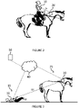
- the system 1 comprises a first device 10 carried by the driver 15 of the vehicle 25 and a second device 20 mounted in or on the vehicle 25.
- connection distance In a standard mode of use of the vehicle by the driver (ie in the absence of an incident), the first device 10 and the second device 20 are spaced apart by a distance, called the “connection distance” DL (in reference to the figure 2 ).
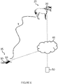
- the system 1 makes it possible to detect a modification of the distance between the first device 10 and the second device 20 in order to determine that the driver 15 and his vehicle 25 have been, at least temporarily, separated ( picture 3 ) and diagnose that an incident has occurred so as to alert one or more third parties 50 (with reference to the figure 3 , 5 and 6 ).
- a modification of the distance between the first device 10 and the second device 20 results from an incident occurring to the driver 15 of the vehicle 25.
- modification of the distance it is understood that the distance between the first device 10 and the second device 20 no longer corresponds to the distance link DL, the distance separating the first device 10 from the second device 20 being called the “separation distance” DS, as illustrated in the picture 3 ).
- the link distance DL corresponds to an average distance or to a distance comprised in an interval of distances outside of which it is considered that there is separation between the pilot 15 and the vehicle 25.
- This interval of distances is adapted to the application targeted and in particular to the type of vehicle 25.
- a modification of the distance between the first device 10 and the second device 20 while the motorcycle is in movement typically corresponds to a fall of the rider 15.
- an increase in the distance between the first device 10 and the second device 20 typically corresponds to a fall of the rider while a reduction in distance may correspond to the rider tipping over the horse's head.
- the link distance DL is between a few centimeters, for example five centimeters, and a few meters, for example the length of the vehicle 25.
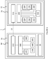
- the first device 10 comprises a plurality of modules fulfilling various functions.
- the first device 10 notably comprises a management module 100 configured to manage the other modules.
- this management module 100 takes the form of a processor or a microcontroller in order to implement various functions.
- the first device 10 firstly comprises a first communication module 110 configured to communicate with the first device 10 on a wireless communication link L1.
- This wireless communication link L1 is a low energy consumption link so as to allow an autonomy of several hours in operating mode and several days in standby mode.
- the wireless communication link L1 can be a Bluetooth® , Bluetooth® low energy (BLE or Bluetooth Low Energy in English) communication link, Zigbee, Wifi or any other suitable communication protocol.
- the first device 10 is configured to detect a change in the distance between the first device 10 and the second device 20. In other words, the first device 10 is configured to detect that the distance which separates it from the second device 20 no longer matches link distance DL, which has for example been predefined. It will be noted that the first device 10 could also be configured to determine the distance which separates it from the second device 20.
- the management module 100 is configured to measure, preferably continuously, the power of the signals transmitted by the second device 20 and received by the first communication module 110 on the wireless communication link L1. In this case, a detection of the modification of the distance separating the first device 10 from the second device 20 is then carried out by the management module 100 when the measured power varies significantly by a predetermined percentage with respect to an average power or a power interval corresponding to the link distance DL (this percentage depending on the intended application).
- the first device 10 and the second device 20 are permanently connected to the wireless communication link L1 in order to be able to detect at any time a modification of the distance between the first device 10 and the second device 20.
- the first device 10 is configured to detect a break in the wireless communication link L1, that is to say the wireless connection between the first device 10 and the second device 20.
- a break detection being known in itself, it will not be further detailed here.
- the first device 10 is configured to send an alert message to a predetermined third party when a change in the distance between the first device 10 and the second device 20 has been detected.
- the first device 10 can comprise a second communication module 120, in order to communicate in particular via a communication network 40 which can for example be cellular or satellite.
- the alert message can for example take the form of a short text message of the SMS type (Short Text Messaging in English), of an email or of any suitable form. It can in particular be transmitted to a server connected to the communication network.
- SMS type Short Text Messaging in English
- the first device 10 is configured to inform the second device 20, for example via the wireless communication link L1 (as long as the connection is made) or a third device 30 that a modification of the distance between the first device 10 and the second device 20 has been detected so that the second device 20 or respectively the third device 30 sends an alert message to a predetermined third party.
- the third device 30 is able to communicate with the first device 10, for example on a Bluetooth® communication link or any other suitable link.
- the third device 30 can be a mobile telephone, for example of the smartphone type, capable of communicating via a communication network 40, in particular cellular or satellite.
- a cellular communication network 40 can be of the GSM, UMTS, LTE type or any suitable network.
- the first device 10 comprises an accelerometer 130, making it possible in particular to determine an impact of the pilot 15 on the ground or on any obstacle. Such a determination can be made when the accelerometer 130 suddenly measures a singular acceleration, for example greater than 200 ms ⁇ 2 in absolute value (preferably greater than 500). The accelerometer 130 can also make it possible to measure the acceleration undergone by the pilot 15 before the impact (at lower absolute values).
- a singular acceleration for example greater than 200 ms ⁇ 2 in absolute value (preferably greater than 500).
- the accelerometer 130 can also make it possible to measure the acceleration undergone by the pilot 15 before the impact (at lower absolute values).
- the first device 10 can also comprise an altimeter (or a barometer) 140 and/or a gyroscope 150.
- the gyroscope 150 makes it possible to diagnose movements recognized as improbable or dangerous such as for example a complete rotation, according to any axis, of the pilot 15 carrying the first device 10.
- the altimeter or barometer 140 respectively make it possible to determine the altitude or the ambient pressure of the first device 10.
- the first device 10 comprises a memory zone 160 which can allow, prior to an exit or a movement, to pre-load the known geographical coordinates of a path as well as some of the characteristics of said coordinates.
- This memory zone 160 can also make it possible, when making a journey, to collect new geographic coordinates or new characteristics concerning these coordinates.
- the memory zone 160 is used to store geographical positions (for example in the form of coordinates) and their characteristics collected in the field.
- the first device 10 could also be equipped with a satellite geolocation module, for example be of the GPS, GALILEO, GLONASS, COMPASS, BEIDOU, IRNSS, QZSS, etc. type.
- a satellite geolocation module for example be of the GPS, GALILEO, GLONASS, COMPASS, BEIDOU, IRNSS, QZSS, etc. type.
- the pilot 15 when equipped with a third device 30, the latter can also comprise such a satellite geolocation module.
- the second device 20 comprises a plurality of modules fulfilling various functions.
- the second device 20 notably comprises a management module 200 configured to manage the other modules.
- this management module 200 takes the form of a processor or a microcontroller electrically connected to the other modules, sensors and memory zone in order to implement their various functions.
- the second device 20 firstly comprises a first communication module 210 configured to communicate with the first device 10 on the wireless communication link L1 described above.
- the second device 20 is configured to determine the distance between the first device 10 and the second device 20 and to detect a modification of this distance for which it no longer corresponds to the link distance DL.
- the determination of the distance between the first device 10 and the second device 20 can be carried out by the second device 20 by measuring the power of the signals transmitted by the first device 10 and received by the first communication module 210 from the second device 20 on the L1 wireless communication link.
- the detection of the modification of the distance between the first device 10 and the second device 20 can be carried out by the second device 20 when the measured power varies significantly by a predetermined percentage with respect to an average power corresponding to the distance of DL link, for example by more than 10%, or when the measured power is no longer included in the power interval corresponding to the DL link distance, as described above.
- the first device 10 and the second device 20 are permanently connected to the wireless communication link L1 in order to detect at any time a modification of the distance between the first device 10 and the second device 20.
- the second device 20 is configured to detect a break in the wireless communication link L1.
- the second device 20 is configured to send an alert message to a predetermined third party 50 when a change in the distance between the first device 10 and the second device 20 has been detected.
- the second device 20 may comprise a communication module 220, in particular in order to communicate via a communication network 40, in particular cellular or satellite.
- the second device 20 may be configured to notify the first device 10 or a third device 30 that a modification of the distance between the first device 10 and the second device 20 has been detected so that the first device 10 or respectively the third device 30 sends an alert message to a predetermined third party 50.
- the third device 30 can be a mobile telephone, for example of the smartphone type, able to communicate via a communication network, in particular cellular 40 or satellite 60.
- the alert message can for example take the form of a short text message of the SMS type (Short Text Messaging in English), of an email or of any suitable form. It can in particular be transmitted to a server connected to the communication network 40.
- the second device 20 comprises a satellite geolocation module 230.
- the positioning of the first device 10 can be achieved by using the position of the second device 20, equipped with said satellite geolocation module 230, and the trajectory followed by the second device 20, for example determined from the last determined geographical position or from the place where the break in the wireless communication link L1 was detected.
- the satellite geolocation module 230 can for example be of the GPS, GALILEO, GLONASS, COMPASS, BEIDOU, IRNSS, QZSS, etc. type.
- the second device 20 is configured to store the last position of the vehicle 25 determined by the satellite geolocation module 230 in a memory zone 240.
- This memory zone 240 can make it possible, prior to an exit or a movement, to pre-load the known geographical coordinates of the path as well as some of the characteristics of said coordinates. This memory zone 240 can also make it possible, when making a journey, to collect new geographic coordinates or new characteristics concerning these coordinates.
- the memory zone 240 is used to store geographical positions (for example in the form of coordinates) and their characteristics collected in the field.
- the management module 200 of the second device 20 is configured to determine the trajectory of the vehicle 25.
- the second device 20 comprises an accelerometer 250 and a magnetometer 260.
- the accelerometer 250 makes it possible to measure the accelerations of the second device 20 while the magnetometer 260 makes it possible to measure the direction followed by the second device 20.
- the acceleration data make it possible to determine the speed of the second device 20 (ie of the vehicle 25).
- the determined speed coupled with the directions measured by the magnetometer 260, makes it possible to determine the trajectory of the second device 20. Such trajectory determination being known per se, it will not be further detailed here.
- the second device 20 is configured to estimate the geographical position of the vehicle 25 from the last geographical position determined by the satellite geolocation module 230 and from the trajectory of the vehicle determined by the management module 200.
- the second device 20 can also comprise a gyroscope 270 and/or an altimeter (or a barometer) 280.
- the gyroscope 270 makes it possible to diagnose movements recognized as improbable or dangerous such as for example a complete rotation, according to any axis, of the vehicle 25 on or in which the second device 20 is mounted.
- the altimeter or the barometer 280 respectively make it possible to determine the altitude or the ambient pressure of the second device 20.
- the invention will be described in its implementation with reference to the figure 4 .
- the first device 10 and the second device 20 are connected to the wireless communication link L1 prior to the occurrence of an incident.
- the first device 10 and/or the second device 20 monitors, in a step E1, the wireless communication link L1, for example by measuring the power of the signals received on said wireless communication link L1 or any another parameter of the wireless communication link L1 that can make it possible to detect a modification of the distance between the first device 10 and the second device 20.
- one of the first device 10 and/or of the second device 20 detects a modification of the distance between the first device 10 and the second device 20. This modification can result from the measurements made in step E1 or else a sudden break in the L1 wireless communication link.
- the first device can detect, in a step E3, a so-called “singular” acceleration relating to an incident occurring to the pilot 15 such as, for example, a fall or a passage, at least temporary, in an abnormal position with respect to the vehicle 25.
- a so-called “singular” acceleration relating to an incident occurring to the pilot 15 such as, for example, a fall or a passage, at least temporary, in an abnormal position with respect to the vehicle 25.
- the second device 20 can request an incident confirmation from the pilot 15 via the first device 10 or a third device 30 in a step E4.
- At least one alert message is sent by one of the first device 10 and/or of the second device 20 or possibly of the third device 30 in a step E5.
- the second device In the absence of a cancellation message from the first device 10 or from the third device 30 intended for the second device 20, the second device sends a wireless link activation message to the third device 30 using the terrestrial or satellite network. .
- the first device 10 configures itself to cooperate with the third device 10 and establishes the pilot's activity report in a step E7.
- the successive activity reports of the pilot 15 established by the first device 10 are transmitted to the third device 30 which periodically sends them to pre-recorded emergency numbers to allow them to follow the evolution of the state of unconsciousness of the pilot 15
- Said activity report comprises the latest measurements of the various devices participating in a Bluetooth link with the first device 10 and the measurement of the activity or inactivity of the pilot 15. Said report is updated periodically.
- Example 1 driver 15 is a rider and vehicle 25 is a horse (figures 2, 3, 5 and 6)
- the first device 10 can for example be mounted on the rider at any suitable place by means of a fastening system.
- the second device 20 can for example be mounted at the level of the highest part of the horse.
- the first device 10 and the second device 20 are connected beforehand via a wireless communication link L1 of the low-energy Bluetooth® type and the geolocation is carried out by a satellite geolocation module 230 of the GPS type.
- the jumper can be equipped with a third device 30 of the smartphone type, able to communicate via a communication network 40, for example cellular or satellite.
- the second device 20 mounted on the horse, determines its geolocation (GPS point) regularly, preferably periodically, via the satellite geolocation module 230. For each new geolocation, the second device 20 determines, depending on the proximity geographical positions already known and characterized, the interest in memorizing a new geolocation position or not.
- GPS point GPS point
- the second device 20 For each geolocation position to be stored, the second device 20 stores the characteristics of the communication network(s) 40 available, and potentially the various measurements available (accelerometric, gyroscopic, magnetometric, barometric, etc.). This makes it possible in particular to improve the safety of the rider by a better knowledge of the environment in which he evolves and by the improvement of the autonomy of the second device 20. By better knowledge, we mean a progressive and selective enrichment of the data catalog already known and a new characterization of the geographical positions already determined beforehand. To increase the autonomy, the second device 20 can in particular space out the geographical position measurements. Moreover, at each loss of signal from the communication network 40 or significant weakening of the level of said signal, the second device 20 can determine the corresponding geographical location and memorize the new point under the same conditions as before.
- the second device 20 comprises an accelerometer 250 and a magnetometer 260 and performs acceleration and orientation measurements at regular intervals so as to estimate a speed and to be able to calculate the trajectory T of the horse if necessary, especially in the event of subsequent loss of GPS signal.
- a location of the second device 20 can be calculated using in particular the accelerations (via the accelerometer 250), the orientation of the magnetometer 260, the time, the cadences of the horse (frequency steps) to reconstruct its trajectory T from the last known geographical position of the second device 20.
- a geographical position of the first device 10 can be calculated from a new geographical position obtained by the second device 20 and of the trajectory T calculated from the place where a modification of the distance between the first device 10 and the second device 20 has been detected.
- a loss of signal from the communication network 40 is detected by the management module 200 of the second device 20, it can for example be indicated to the jumper by means of a diode and a color code materializing the impossibility of transmitting. any warning message.
- the first device 10 When the rider falls, the first device 10 firstly detects a sudden lengthening of the distance vis-à-vis the second device 20 and then detects an impact characterized by an acceleration value greater than a predefined threshold, by example at 500 ms -2 .
- the first device 10 records acceleration, gyroscopic, barometric and magnetometric values for a predefined time then transmits these values instantaneously to the second device 20 on the wireless communication link L1 as long as this link is maintained.
- the set of measured values is called the "rider's balance”.
- the first device 10 calculates the evolution of the distance vis-à-vis the second device.
- the intensity of the impact is measured (in g) and gives rise to the evaluation of a level of severity according to the value calculated with regard to a determined scale.
- the first device 10 launches an algorithm for detecting the immobility of the rider based on the various accelerometric, gyroscopic, magnetometric and barometric values for a predefined time, for example 5 seconds, which constitutes a new assessment of the rider. .
- This algorithm is restarted at regular intervals.
- the reports established by the first device 10 are sent to the second device 20 on the wireless communication link L1 as long as said wireless communication link L1 is established between the first device 10 and the second device 20.
- the reports can also be relayed by the rider's smartphone in the event of loss of the wireless communication link L1 between the first device 10 and the second device 20.
- the second device 20 performs a calculation of the trajectory T of the horse advantageously using its magnetometer 260, its accelerometer 250 as described above and determines the geographical position (GPS point) in order to know both its position and to deduce therefrom, using the determined trajectory T, that of the injured rider.
- GPS point geographical position
- the second device 20 delivers to a third party 50, via the cellular communication network 40 and depending on the existence of a sufficient signal level thereof, the positions regular geographical (GPS points) of the second device 20, as well as the last known information of the first device 10, for example the last real data sent by the first device 10 to the second device 20 before the wireless communication link L1 was broken.
- a third party 50 via the cellular communication network 40 and depending on the existence of a sufficient signal level thereof, the positions regular geographical (GPS points) of the second device 20, as well as the last known information of the first device 10, for example the last real data sent by the first device 10 to the second device 20 before the wireless communication link L1 was broken.
- the increase in the distance vis-à-vis the first device 10 triggers the determination of the geographical location, the calculation of the trajectory T of the second device 20, the calculation of the height (via the altimeter or the barometer 280) and its transmission to the first device 10.
- This process can also be event-driven in the case where the second device 20 receives a message on the wireless communication link L1 which is characterized by a value of significant acceleration recorded by the first device 10, corresponding to a fall of the rider, characterized by the various measurements available.
- the alert confirmation cycle is triggered.
- the first device 10 After the immobility detection phase, and if the need is confirmed, the first device 10 connects to the third device 30, if it is accessible, for example on a Bluetooth ® communication link, so as to use the access to the communication network 40 provided by said third device 30 in order to transmit the new information provided by the first device 10.
- a geographical position of the separation of the rider from his horse may be established using the calculated displacement and the GPS position which will be obtained later when the GPS signal will be available again.
- the last known GPS position before the separation can be instantly broadcast in order to allow the orientation of the emergency services while waiting for a more precise point obtained by the calculation carried out.
- the second device 20 performs regular GPS points (configurable interval) and transmits them via the communication network 40 to the (third party) contacts 50 predetermined.
- the calculation of the movement of the horse remains active. In the absence of a signal received from the cellular communication network 40, the GPS points continue to be made.
- the geographical points are calculated and transmitted via the communication network 40.
- the geographical points are also calculated and stored, but not transmitted. They could, for example, be used later to find the horse and/or the rider.
- the Bluetooth ® link is maintained because the horse remains next to the rider, it is considered that the injured, unconscious or injured rider remains lying on the ground.
- the separation of the rider and the horse causes an increase in the distance between the first device 10 and the second device 20.
- the impact of the fall is also detected by the first device 10.
- the first device 10 transmits following the increase in distance and the detection of an impact, periodically, on the Bluetooth® link and as long as the wireless communication link L1 is maintained, the values d acceleration, gyroscopic, magnetometric and altimetric to characterize the rider's fall.
- the second device 20 Upon receipt of the messages from the first device 10, the second device 20 determines its own altitude and compares it with the altitude of the first device 10 received on the wireless communication link L1 in order to determine whether the first device 10 is at the ground level, for example when the difference in altitude is greater than 1.20 meters.
- An algorithm aimed at establishing the immobility of the rider is then launched in order to establish the unconsciousness of the rider. Reviewing these conditions activates the alert confirmation scenario.
- the altitude of the horse's headrest and that of the first device 10 By using, for example, the altitude of the horse's headrest and that of the first device 10 and by knowing the height of the rider, the height of the horse at the withers, the distance from the withers to the horse's headrest, and by determining a minimum area at the above the geographical altitude equal to (0.48 x h), it is determined whether or not there is an alert.
- the alert cycle will be triggered.
- the same type of altimeter is used in the first device 10 and in the second device 20 in order to have identical precision.
- the various parameters taken into account can be modified in order to be adapted to the size of the rider carrying the system.
- Example 2 vehicle drawn by animals
- a pilot or a passenger is equipped with the first device 10 (even a plurality of pilots and/or passengers are each equipped with a first device 10) and the second device 20 is mounted on the towed vehicle.
- the determination of the distance is preferably carried out by the first device 10 (or one of the first devices 10).
- each pilot and passenger may wear a first device 10 and have designated a different third party to alert so that alerts may be sent to different people depending on the first device involved in the incident.
- the first device 10 Connected for example via a wireless communication link L1 of the Bluetooth® type to the second device 20 attached to the motorcycle, the first device 10, attached to the rider or to his helmet, advantageously integrated into his helmet, continuously calculates the distance between the first device 10 and the second device 20.
- This distance which is preferably less than the length of the motorcycle, can be configured so as to determine a safety zone around the vehicle.
- the sudden increase in distance triggers the alert process similar to the previous example.
- the signal will be sent to trusted third parties or emergency centres.
Landscapes
- Physics & Mathematics (AREA)
- General Physics & Mathematics (AREA)
- Business, Economics & Management (AREA)
- Emergency Management (AREA)
- Health & Medical Sciences (AREA)
- General Health & Medical Sciences (AREA)
- Child & Adolescent Psychology (AREA)
- Engineering & Computer Science (AREA)
- Computer Security & Cryptography (AREA)
- Gerontology & Geriatric Medicine (AREA)
- Alarm Systems (AREA)
- Traffic Control Systems (AREA)
- Emergency Alarm Devices (AREA)
Claims (13)
- Warnverfahren infolge eines Vorkommnisses, das sich für einen Fahrer (15) eines Fahrzeugs (25) ereignet hat, das, wobei der Fahrer (15) mit einer ersten Vorrichtung (10) ausgerüstet ist und das Fahrzeug (25) mit einer zweiten Vorrichtung (20) ausgerüstet ist, wobei die erste Vorrichtung (10) und die zweite Vorrichtung (20) über eine drahtlose Kommunikationsverbindung (L1) vor dem Auftreten des Vorkommnisses verbunden wurden, die folgenden Schritte umfasst:- einen Schritt (E2) der Ermittlung einer Veränderung des Abstands zwischen der ersten Vorrichtung (10) und der zweiten Vorrichtung (20) ausgehend von der drahtlosen Kommunikationsverbindung (L1),- einen Schritt (E3) der Ermittlung einer als "singulär" bezeichneten Beschleunigung in Verbindung mit einem Vorkommnis, das sich für den Fahrer (15) ereignet hat, durch die erste Vorrichtung (10),- infolge der Detektion der singulären Beschleunigung durch die erste Vorrichtung (10) einen Schritt (E4) der Bestätigung des Vorkommnisses,- einen Schritt (E5) des Versands mindestens einer Warnmeldung, wenn eine Veränderung des Abstands zwischen der ersten Vorrichtung (10) und der zweiten Vorrichtung (20) ermittelt und das Vorkommnisses bestätigt wurde,- einen Schritt der Bestimmung der Bahn des Fahrzeugs (25) ab der Ermittlung des Vorkommnisses durch die zweite Vorrichtung (20),- einen Schritt der Bestimmung der geografischen Position der zweiten Vorrichtung (20) durch die zweite Vorrichtung (20),- einen Schritt der Schätzung der geografischen Position der ersten Vorrichtung (10) ausgehend von der bestimmten geografischen Position der zweiten Vorrichtung (20) und von der bestimmten Bahn des Fahrzeugs (25).
- Verfahren nach Anspruch 1, wobei die Ermittlung der Veränderung des Abstands zwischen der ersten Vorrichtung (10) und der zweiten Vorrichtung (20) durch die erste Vorrichtung (10) und/oder durch die zweite Vorrichtung (20) durchgeführt wird.
- Verfahren nach einem der Ansprüche 1 und 2, wobei die Ermittlung der Veränderung des Abstands zwischen der ersten Vorrichtung (10) und der zweiten Vorrichtung (20) durch Messen der Leistung der über die drahtlose Kommunikationsverbindung (L1) empfangenen Signale und durch deren Vergleichen mit einer mittleren Leistung, die einem mittleren Abstand, bezeichnet als "Verbindungsabstand" (DL), zwischen der ersten Vorrichtung (10) und der zweiten Vorrichtung (20) oder mit einem Leistungsintervall, das einem Abstandsintervall, bezeichnet als "Verbindungsabstand" (DL), zwischen der ersten Vorrichtung (10) und der zweiten Vorrichtung (20) entspricht, durchgeführt wird.
- Verfahren nach einem der vorangehenden Ansprüche, wobei der Versand der Warnmeldung durch die erste Vorrichtung (10) und/oder durch die zweite Vorrichtung (20) und/oder durch eine dritte Vorrichtung (30) durchgeführt wird.
- Verfahren nach einem der vorangehenden Ansprüche, wobei das Verfahren ferner einen Schritt der Ermittlung einer Unterbrechung der Verbindung zwischen der ersten Vorrichtung (10) und der zweiten Vorrichtung (20) umfasst.
- Verfahren nach einem der vorangehenden Ansprüche, das, wobei die Veränderung des Abstands relativ zum Vorkommnis durch die erste Vorrichtung (10) ermittelt wird, einen Schritt des Versands einer Information, die angibt, dass der Abstand verändert wurde, durch die erste Vorrichtung (10) an die zweite Vorrichtung (20) umfasst.
- Verfahren nach einem der vorangehenden Ansprüche, wobei das Vorkommnis einem Sturz des Fahrers (15) oder einem mindestens zeitweiligen Übergang des Fahrers (15) in eine anormale Position im Verhältnis zum Fahrzeug (25) entspricht.
- Verfahren nach einem der vorangehenden Ansprüche, wobei die Warnmeldung die geografische Position der ersten Vorrichtung (10) und/oder die geografische Position der zweiten Vorrichtung (20) umfasst.
- Verfahren nach einem der vorangehenden Ansprüche, das die periodische Bestimmung und den Versand der geografischen Position des Fahrzeugs umfasst.
- Warnsystem (1) infolge eines Vorkommnisses, das sich für einen Fahrer (15) eines Fahrzeugs (25) ereignet hat, wobei das System eine erste Vorrichtung (10), die imstande ist, vom Fahrer (15) getragen zu werden, und eine zweite Vorrichtung (20), die imstande ist, im oder auf dem Fahrzeug (25) angebracht zu sein, umfasst, wobei die erste Vorrichtung (10) und die zweite Vorrichtung (20) imstande sind, (L1) vor dem Auftreten des Vorkommnisses über eine drahtlose Kommunikationsverbindung verbunden zu sein, wobei mindestens eine von der ersten Vorrichtung (10) und der zweiten Vorrichtung (20) imstande ist, eine Veränderung des Abstands zwischen der ersten Vorrichtung (10) und der zweiten Vorrichtung (20) ausgehend von der drahtlosen Kommunikationsverbindung (L1) zu ermitteln und mindestens eine von der ersten Vorrichtung (10) und der zweiten Vorrichtung (20) imstande ist, den Versand von mindestens einer Warnmeldung auszulösen, wobei die erste Vorrichtung (10) ferner ausgelegt ist, um eine singuläre Beschleunigung relativ zu einem Vorkommnis, das sich für den Fahrer (15) ereignet hat, zu ermitteln und das Vorkommnis vor dem Versand der Warnmeldung ausgehend von der singulären Beschleunigung zu bestätigen, wobei die zweite Vorrichtung (20) ausgelegt ist, um die Bahn des Fahrzeugs (25) ab der Ermittlung des Vorkommnisses zu bestimmen, die geografische Position der zweiten Vorrichtung (20) zu bestimmen und die geografische Position der ersten Vorrichtung (10) ausgehend von der bestimmten geografischen Position der zweiten Vorrichtung (20) und von der bestimmten Bahn des Fahrzeugs (25) zu bestimmen.
- System nach Anspruch 10, wobei die erste Vorrichtung (10) ausgelegt ist, um einen aktiven oder inaktiven Zustand des Fahrers (15) zu ermitteln.
- System nach einem der Ansprüche 10 oder 11, wobei die erste Vorrichtung (10) ausgelegt ist, um die mit der zweiten Vorrichtung (20) hergestellte drahtlose Verbindung auf eine dritte Vorrichtung (30) zu übertragen.
- System nach einem der Ansprüche 10 bis 12, wobei die erste Vorrichtung (10) ausgelegt ist, um vor dem Versand der Warnmeldung die Stornierung der Warnmeldung vorzuschlagen.
Applications Claiming Priority (2)
| Application Number | Priority Date | Filing Date | Title |
|---|---|---|---|
| FR1753373A FR3065563B1 (fr) | 2017-04-19 | 2017-04-19 | Procede et systeme d'alerte suite a la separation d'un pilote et de son vehicule |
| PCT/EP2018/060099 WO2018193056A1 (fr) | 2017-04-19 | 2018-04-19 | Procede et systeme d'alerte suite a la separation d'un pilote et de son vehicule |
Publications (2)
| Publication Number | Publication Date |
|---|---|
| EP3420545A1 EP3420545A1 (de) | 2019-01-02 |
| EP3420545B1 true EP3420545B1 (de) | 2023-01-18 |
Family
ID=59649816
Family Applications (1)
| Application Number | Title | Priority Date | Filing Date |
|---|---|---|---|
| EP18717100.4A Active EP3420545B1 (de) | 2017-04-19 | 2018-04-19 | Warnverfahren und system nach der trennung eines fahrers von seinem fahrzeug |
Country Status (3)
| Country | Link |
|---|---|
| EP (1) | EP3420545B1 (de) |
| FR (1) | FR3065563B1 (de) |
| WO (1) | WO2018193056A1 (de) |
Families Citing this family (5)
| Publication number | Priority date | Publication date | Assignee | Title |
|---|---|---|---|---|
| DE102019208483A1 (de) * | 2019-06-11 | 2020-12-17 | Robert Bosch Gmbh | Verfahren und Vorrichtung zur Ermittlung sich annähernder Funksignalquellen an ein in einen Unfall verwickeltes Unfallfahrzeug |
| JP7582890B2 (ja) * | 2021-03-24 | 2024-11-13 | 本田技研工業株式会社 | プログラム、情報処理方法、及びシステム |
| JP7620465B2 (ja) * | 2021-03-24 | 2025-01-23 | 本田技研工業株式会社 | プログラム、鞍乗型車両、及びシステム |
| JP7614902B2 (ja) * | 2021-03-24 | 2025-01-16 | 本田技研工業株式会社 | プログラム、情報処理方法、及びシステム |
| JP7664066B2 (ja) * | 2021-03-24 | 2025-04-17 | 本田技研工業株式会社 | プログラム、及びシステム |
Family Cites Families (9)
| Publication number | Priority date | Publication date | Assignee | Title |
|---|---|---|---|---|
| GB2389216B (en) * | 2002-05-30 | 2004-12-29 | Kenneth Dolman | Proximity system |
| FR2842493B1 (fr) | 2002-07-18 | 2005-09-09 | De Meder Laurent Bourgine | Procede et dispositif de securite pour vehicule deux roues et similaires |
| GB2481605A (en) * | 2010-06-29 | 2012-01-04 | Mary Thompson | Apparatus for raising an alarm following a fall from a horse, bicycle or motorcycle |
| GB2511099A (en) * | 2013-02-22 | 2014-08-27 | Scorpion Automotive Ltd | Power saving vehicle tracking |
| JP2015110385A (ja) * | 2013-12-06 | 2015-06-18 | アルプス電気株式会社 | 車載事故報知装置 |
| DE102014202620A1 (de) * | 2014-02-13 | 2015-08-13 | Robert Bosch Gmbh | Verfahren zum Erkennen eines Unfalls |
| US9449495B1 (en) * | 2015-05-15 | 2016-09-20 | State Farm Mutual Automobile Insurance Company | Crash detection and severity classification system implementing emergency assistance |
| DE102015215375A1 (de) * | 2015-08-12 | 2017-02-16 | Digades Gmbh Digitales Und Analoges Schaltungsdesign | Vorrichtung zum Erkennen einer Unfallsituation eines Straßenfahrzeugs |
| DK201600104A1 (da) * | 2016-02-23 | 2017-09-11 | Dorthe Schellerup | Safety Tracker |
-
2017
- 2017-04-19 FR FR1753373A patent/FR3065563B1/fr active Active
-
2018
- 2018-04-19 EP EP18717100.4A patent/EP3420545B1/de active Active
- 2018-04-19 WO PCT/EP2018/060099 patent/WO2018193056A1/fr not_active Ceased
Also Published As
| Publication number | Publication date |
|---|---|
| FR3065563B1 (fr) | 2020-11-06 |
| EP3420545A1 (de) | 2019-01-02 |
| FR3065563A1 (fr) | 2018-10-26 |
| WO2018193056A1 (fr) | 2018-10-25 |
Similar Documents
| Publication | Publication Date | Title |
|---|---|---|
| EP3420545B1 (de) | Warnverfahren und system nach der trennung eines fahrers von seinem fahrzeug | |
| US9491420B2 (en) | Vehicle security with accident notification and embedded driver analytics | |
| US20150046046A1 (en) | System for detecting vehicle driving mode and method of conducting the same | |
| US20160180721A1 (en) | System and method for tracking, surveillance and remote control of powered personal recreational vehicles | |
| US20100302029A1 (en) | Transmission of an emergency call from a motor cycle | |
| JP6318785B2 (ja) | 車両情報処理システム | |
| WO2018230324A1 (ja) | 車載通信装置、車両異常検出システム、車両異常通知方法及びコンピュータプログラム | |
| CN105263757A (zh) | 用于在使用可与车辆耦合的移动终端设备的情况下识别车辆和对象之间的碰撞的方法和设备 | |
| FR2930195A1 (fr) | Procede et dispositif de pre-alerte pour vehicule | |
| EP3227155B1 (de) | Verfahren zur unterstützung von mindestens einem insassen eines von einem unfall betroffenen fahrzeugs und dediziertes hilfssystem | |
| EP3700173A1 (de) | Fernüberwachungssystem einer flotte von autonomen kraftfahrzeugen, entsprechendes transportsystem und spannverfahren | |
| US20240386730A1 (en) | Inattentiveness determination device, inattentiveness determination system, inattentiveness determination method, and storage medium for storing program | |
| JP2023548762A (ja) | 車両危険状態検出のためのシステム及び方法 | |
| EP3963560B1 (de) | Verfahren zur warnung eines nachfolgenden fahrzeugs, das einen sicherheitsabstand nicht einhält | |
| CN110091990B (zh) | 一种交通事故应急方法及无人机 | |
| GB2485581A (en) | Method of alerting the driver of a vehicle of an accident risk | |
| FR3014233A1 (fr) | Systeme d'aeronef pour signaler la presence d'un obstacle, aeronef et procede de detection d'obstacle | |
| TWI815799B (zh) | 車輛安全系統及其方法 | |
| JP6562964B2 (ja) | 車載器 | |
| WO2015082834A1 (fr) | Système de transport par câble aérien, notamment un télésiège ou télécabine | |
| FR3096861A1 (fr) | Procédé de génération de message de connaissance d’un premier usager de la route, et procédé et dispositif d’assistance d’un deuxième usager de la route | |
| JP7364438B2 (ja) | 速度データ取得装置、サービス提供システム及び速度データ取得方法 | |
| JP2022074441A (ja) | ドライバ状態推定装置、ドライバ状態推定プログラム、運行日報生成方法、及び、運行日報 | |
| FR2718552A1 (fr) | Procédé et dispositif pour la localisation et l'acheminement de secours vers un véhicule accidenté. | |
| FR3115912A1 (fr) | Dispositif avertisseur de danger électrique |
Legal Events
| Date | Code | Title | Description |
|---|---|---|---|
| STAA | Information on the status of an ep patent application or granted ep patent |
Free format text: STATUS: UNKNOWN |
|
| STAA | Information on the status of an ep patent application or granted ep patent |
Free format text: STATUS: THE INTERNATIONAL PUBLICATION HAS BEEN MADE |
|
| PUAI | Public reference made under article 153(3) epc to a published international application that has entered the european phase |
Free format text: ORIGINAL CODE: 0009012 |
|
| STAA | Information on the status of an ep patent application or granted ep patent |
Free format text: STATUS: REQUEST FOR EXAMINATION WAS MADE |
|
| 17P | Request for examination filed |
Effective date: 20180427 |
|
| AK | Designated contracting states |
Kind code of ref document: A1 Designated state(s): AL AT BE BG CH CY CZ DE DK EE ES FI FR GB GR HR HU IE IS IT LI LT LU LV MC MK MT NL NO PL PT RO RS SE SI SK SM TR |
|
| AX | Request for extension of the european patent |
Extension state: BA ME |
|
| RIN1 | Information on inventor provided before grant (corrected) |
Inventor name: CHAVENTRE, CATHERINE Inventor name: LE CAMUS, CHRISTOPHE |
|
| STAA | Information on the status of an ep patent application or granted ep patent |
Free format text: STATUS: EXAMINATION IS IN PROGRESS |
|
| 17Q | First examination report despatched |
Effective date: 20200414 |
|
| DAV | Request for validation of the european patent (deleted) | ||
| DAX | Request for extension of the european patent (deleted) | ||
| RIC1 | Information provided on ipc code assigned before grant |
Ipc: G08G 1/00 20060101ALI20211110BHEP Ipc: G08B 21/04 20060101ALI20211110BHEP Ipc: G08B 21/02 20060101ALI20211110BHEP Ipc: G08B 25/01 20060101AFI20211110BHEP |
|
| GRAP | Despatch of communication of intention to grant a patent |
Free format text: ORIGINAL CODE: EPIDOSNIGR1 |
|
| STAA | Information on the status of an ep patent application or granted ep patent |
Free format text: STATUS: GRANT OF PATENT IS INTENDED |
|
| INTG | Intention to grant announced |
Effective date: 20220110 |
|
| GRAS | Grant fee paid |
Free format text: ORIGINAL CODE: EPIDOSNIGR3 |
|
| GRAA | (expected) grant |
Free format text: ORIGINAL CODE: 0009210 |
|
| STAA | Information on the status of an ep patent application or granted ep patent |
Free format text: STATUS: THE PATENT HAS BEEN GRANTED |
|
| AK | Designated contracting states |
Kind code of ref document: B1 Designated state(s): AL AT BE BG CH CY CZ DE DK EE ES FI FR GB GR HR HU IE IS IT LI LT LU LV MC MK MT NL NO PL PT RO RS SE SI SK SM TR |
|
| REG | Reference to a national code |
Ref country code: GB Ref legal event code: FG4D Free format text: NOT ENGLISH |
|
| REG | Reference to a national code |
Ref country code: DE Ref legal event code: R096 Ref document number: 602018045499 Country of ref document: DE |
|
| REG | Reference to a national code |
Ref country code: CH Ref legal event code: EP |
|
| REG | Reference to a national code |
Ref country code: AT Ref legal event code: REF Ref document number: 1545122 Country of ref document: AT Kind code of ref document: T Effective date: 20230215 Ref country code: IE Ref legal event code: FG4D Free format text: LANGUAGE OF EP DOCUMENT: FRENCH |
|
| REG | Reference to a national code |
Ref country code: LT Ref legal event code: MG9D |
|
| REG | Reference to a national code |
Ref country code: NL Ref legal event code: MP Effective date: 20230118 |
|
| REG | Reference to a national code |
Ref country code: AT Ref legal event code: MK05 Ref document number: 1545122 Country of ref document: AT Kind code of ref document: T Effective date: 20230118 |
|
| PG25 | Lapsed in a contracting state [announced via postgrant information from national office to epo] |
Ref country code: NL Free format text: LAPSE BECAUSE OF FAILURE TO SUBMIT A TRANSLATION OF THE DESCRIPTION OR TO PAY THE FEE WITHIN THE PRESCRIBED TIME-LIMIT Effective date: 20230118 |
|
| PG25 | Lapsed in a contracting state [announced via postgrant information from national office to epo] |
Ref country code: RS Free format text: LAPSE BECAUSE OF FAILURE TO SUBMIT A TRANSLATION OF THE DESCRIPTION OR TO PAY THE FEE WITHIN THE PRESCRIBED TIME-LIMIT Effective date: 20230118 Ref country code: PT Free format text: LAPSE BECAUSE OF FAILURE TO SUBMIT A TRANSLATION OF THE DESCRIPTION OR TO PAY THE FEE WITHIN THE PRESCRIBED TIME-LIMIT Effective date: 20230518 Ref country code: NO Free format text: LAPSE BECAUSE OF FAILURE TO SUBMIT A TRANSLATION OF THE DESCRIPTION OR TO PAY THE FEE WITHIN THE PRESCRIBED TIME-LIMIT Effective date: 20230418 Ref country code: LV Free format text: LAPSE BECAUSE OF FAILURE TO SUBMIT A TRANSLATION OF THE DESCRIPTION OR TO PAY THE FEE WITHIN THE PRESCRIBED TIME-LIMIT Effective date: 20230118 Ref country code: LT Free format text: LAPSE BECAUSE OF FAILURE TO SUBMIT A TRANSLATION OF THE DESCRIPTION OR TO PAY THE FEE WITHIN THE PRESCRIBED TIME-LIMIT Effective date: 20230118 Ref country code: HR Free format text: LAPSE BECAUSE OF FAILURE TO SUBMIT A TRANSLATION OF THE DESCRIPTION OR TO PAY THE FEE WITHIN THE PRESCRIBED TIME-LIMIT Effective date: 20230118 Ref country code: ES Free format text: LAPSE BECAUSE OF FAILURE TO SUBMIT A TRANSLATION OF THE DESCRIPTION OR TO PAY THE FEE WITHIN THE PRESCRIBED TIME-LIMIT Effective date: 20230118 Ref country code: AT Free format text: LAPSE BECAUSE OF FAILURE TO SUBMIT A TRANSLATION OF THE DESCRIPTION OR TO PAY THE FEE WITHIN THE PRESCRIBED TIME-LIMIT Effective date: 20230118 |
|
| PG25 | Lapsed in a contracting state [announced via postgrant information from national office to epo] |
Ref country code: SE Free format text: LAPSE BECAUSE OF FAILURE TO SUBMIT A TRANSLATION OF THE DESCRIPTION OR TO PAY THE FEE WITHIN THE PRESCRIBED TIME-LIMIT Effective date: 20230118 Ref country code: PL Free format text: LAPSE BECAUSE OF FAILURE TO SUBMIT A TRANSLATION OF THE DESCRIPTION OR TO PAY THE FEE WITHIN THE PRESCRIBED TIME-LIMIT Effective date: 20230118 Ref country code: IS Free format text: LAPSE BECAUSE OF FAILURE TO SUBMIT A TRANSLATION OF THE DESCRIPTION OR TO PAY THE FEE WITHIN THE PRESCRIBED TIME-LIMIT Effective date: 20230518 Ref country code: GR Free format text: LAPSE BECAUSE OF FAILURE TO SUBMIT A TRANSLATION OF THE DESCRIPTION OR TO PAY THE FEE WITHIN THE PRESCRIBED TIME-LIMIT Effective date: 20230419 Ref country code: FI Free format text: LAPSE BECAUSE OF FAILURE TO SUBMIT A TRANSLATION OF THE DESCRIPTION OR TO PAY THE FEE WITHIN THE PRESCRIBED TIME-LIMIT Effective date: 20230118 |
|
| REG | Reference to a national code |
Ref country code: DE Ref legal event code: R097 Ref document number: 602018045499 Country of ref document: DE |
|
| PG25 | Lapsed in a contracting state [announced via postgrant information from national office to epo] |
Ref country code: SM Free format text: LAPSE BECAUSE OF FAILURE TO SUBMIT A TRANSLATION OF THE DESCRIPTION OR TO PAY THE FEE WITHIN THE PRESCRIBED TIME-LIMIT Effective date: 20230118 Ref country code: RO Free format text: LAPSE BECAUSE OF FAILURE TO SUBMIT A TRANSLATION OF THE DESCRIPTION OR TO PAY THE FEE WITHIN THE PRESCRIBED TIME-LIMIT Effective date: 20230118 Ref country code: EE Free format text: LAPSE BECAUSE OF FAILURE TO SUBMIT A TRANSLATION OF THE DESCRIPTION OR TO PAY THE FEE WITHIN THE PRESCRIBED TIME-LIMIT Effective date: 20230118 Ref country code: DK Free format text: LAPSE BECAUSE OF FAILURE TO SUBMIT A TRANSLATION OF THE DESCRIPTION OR TO PAY THE FEE WITHIN THE PRESCRIBED TIME-LIMIT Effective date: 20230118 Ref country code: CZ Free format text: LAPSE BECAUSE OF FAILURE TO SUBMIT A TRANSLATION OF THE DESCRIPTION OR TO PAY THE FEE WITHIN THE PRESCRIBED TIME-LIMIT Effective date: 20230118 |
|
| PLBE | No opposition filed within time limit |
Free format text: ORIGINAL CODE: 0009261 |
|
| STAA | Information on the status of an ep patent application or granted ep patent |
Free format text: STATUS: NO OPPOSITION FILED WITHIN TIME LIMIT |
|
| PG25 | Lapsed in a contracting state [announced via postgrant information from national office to epo] |
Ref country code: SK Free format text: LAPSE BECAUSE OF FAILURE TO SUBMIT A TRANSLATION OF THE DESCRIPTION OR TO PAY THE FEE WITHIN THE PRESCRIBED TIME-LIMIT Effective date: 20230118 |
|
| REG | Reference to a national code |
Ref country code: CH Ref legal event code: PL |
|
| 26N | No opposition filed |
Effective date: 20231019 |
|
| PG25 | Lapsed in a contracting state [announced via postgrant information from national office to epo] |
Ref country code: LU Free format text: LAPSE BECAUSE OF NON-PAYMENT OF DUE FEES Effective date: 20230419 |
|
| REG | Reference to a national code |
Ref country code: BE Ref legal event code: MM Effective date: 20230430 |
|
| PG25 | Lapsed in a contracting state [announced via postgrant information from national office to epo] |
Ref country code: MC Free format text: LAPSE BECAUSE OF FAILURE TO SUBMIT A TRANSLATION OF THE DESCRIPTION OR TO PAY THE FEE WITHIN THE PRESCRIBED TIME-LIMIT Effective date: 20230118 |
|
| PG25 | Lapsed in a contracting state [announced via postgrant information from national office to epo] |
Ref country code: SI Free format text: LAPSE BECAUSE OF FAILURE TO SUBMIT A TRANSLATION OF THE DESCRIPTION OR TO PAY THE FEE WITHIN THE PRESCRIBED TIME-LIMIT Effective date: 20230118 Ref country code: MC Free format text: LAPSE BECAUSE OF FAILURE TO SUBMIT A TRANSLATION OF THE DESCRIPTION OR TO PAY THE FEE WITHIN THE PRESCRIBED TIME-LIMIT Effective date: 20230118 Ref country code: LI Free format text: LAPSE BECAUSE OF NON-PAYMENT OF DUE FEES Effective date: 20230430 Ref country code: CH Free format text: LAPSE BECAUSE OF NON-PAYMENT OF DUE FEES Effective date: 20230430 |
|
| REG | Reference to a national code |
Ref country code: IE Ref legal event code: MM4A |
|
| PG25 | Lapsed in a contracting state [announced via postgrant information from national office to epo] |
Ref country code: BE Free format text: LAPSE BECAUSE OF NON-PAYMENT OF DUE FEES Effective date: 20230430 |
|
| PG25 | Lapsed in a contracting state [announced via postgrant information from national office to epo] |
Ref country code: IE Free format text: LAPSE BECAUSE OF NON-PAYMENT OF DUE FEES Effective date: 20230419 |
|
| PG25 | Lapsed in a contracting state [announced via postgrant information from national office to epo] |
Ref country code: IE Free format text: LAPSE BECAUSE OF NON-PAYMENT OF DUE FEES Effective date: 20230419 |
|
| PG25 | Lapsed in a contracting state [announced via postgrant information from national office to epo] |
Ref country code: IT Free format text: LAPSE BECAUSE OF FAILURE TO SUBMIT A TRANSLATION OF THE DESCRIPTION OR TO PAY THE FEE WITHIN THE PRESCRIBED TIME-LIMIT Effective date: 20230118 |
|
| PG25 | Lapsed in a contracting state [announced via postgrant information from national office to epo] |
Ref country code: BG Free format text: LAPSE BECAUSE OF FAILURE TO SUBMIT A TRANSLATION OF THE DESCRIPTION OR TO PAY THE FEE WITHIN THE PRESCRIBED TIME-LIMIT Effective date: 20230118 |
|
| PG25 | Lapsed in a contracting state [announced via postgrant information from national office to epo] |
Ref country code: BG Free format text: LAPSE BECAUSE OF FAILURE TO SUBMIT A TRANSLATION OF THE DESCRIPTION OR TO PAY THE FEE WITHIN THE PRESCRIBED TIME-LIMIT Effective date: 20230118 |
|
| PGFP | Annual fee paid to national office [announced via postgrant information from national office to epo] |
Ref country code: DE Payment date: 20250422 Year of fee payment: 8 |
|
| PGFP | Annual fee paid to national office [announced via postgrant information from national office to epo] |
Ref country code: GB Payment date: 20250423 Year of fee payment: 8 |
|
| PGFP | Annual fee paid to national office [announced via postgrant information from national office to epo] |
Ref country code: FR Payment date: 20250425 Year of fee payment: 8 |
|
| PG25 | Lapsed in a contracting state [announced via postgrant information from national office to epo] |
Ref country code: CY Free format text: LAPSE BECAUSE OF FAILURE TO SUBMIT A TRANSLATION OF THE DESCRIPTION OR TO PAY THE FEE WITHIN THE PRESCRIBED TIME-LIMIT; INVALID AB INITIO Effective date: 20180419 |
|
| PG25 | Lapsed in a contracting state [announced via postgrant information from national office to epo] |
Ref country code: HU Free format text: LAPSE BECAUSE OF FAILURE TO SUBMIT A TRANSLATION OF THE DESCRIPTION OR TO PAY THE FEE WITHIN THE PRESCRIBED TIME-LIMIT; INVALID AB INITIO Effective date: 20180419 |
|
| PG25 | Lapsed in a contracting state [announced via postgrant information from national office to epo] |
Ref country code: TR Free format text: LAPSE BECAUSE OF FAILURE TO SUBMIT A TRANSLATION OF THE DESCRIPTION OR TO PAY THE FEE WITHIN THE PRESCRIBED TIME-LIMIT Effective date: 20230118 |