EP3420207B1 - Nettoyage de filtre - Google Patents
Nettoyage de filtre Download PDFInfo
- Publication number
- EP3420207B1 EP3420207B1 EP17704026.8A EP17704026A EP3420207B1 EP 3420207 B1 EP3420207 B1 EP 3420207B1 EP 17704026 A EP17704026 A EP 17704026A EP 3420207 B1 EP3420207 B1 EP 3420207B1
- Authority
- EP
- European Patent Office
- Prior art keywords
- filter
- stage
- vibration
- pressure
- particulate filter
- Prior art date
- Legal status (The legal status is an assumption and is not a legal conclusion. Google has not performed a legal analysis and makes no representation as to the accuracy of the status listed.)
- Active
Links
- 238000004140 cleaning Methods 0.000 title claims description 44
- 238000000034 method Methods 0.000 claims description 60
- 238000007789 sealing Methods 0.000 claims description 9
- 230000001105 regulatory effect Effects 0.000 claims description 4
- 239000002245 particle Substances 0.000 description 25
- 230000008569 process Effects 0.000 description 15
- 239000004071 soot Substances 0.000 description 8
- 238000005259 measurement Methods 0.000 description 7
- 239000000243 solution Substances 0.000 description 6
- 238000013459 approach Methods 0.000 description 5
- 239000000919 ceramic Substances 0.000 description 5
- 230000008929 regeneration Effects 0.000 description 5
- 238000011069 regeneration method Methods 0.000 description 5
- 239000012530 fluid Substances 0.000 description 4
- 238000013019 agitation Methods 0.000 description 3
- 238000007664 blowing Methods 0.000 description 3
- 238000001035 drying Methods 0.000 description 3
- 239000003921 oil Substances 0.000 description 3
- 230000035939 shock Effects 0.000 description 3
- 239000000126 substance Substances 0.000 description 3
- 230000001276 controlling effect Effects 0.000 description 2
- 238000005108 dry cleaning Methods 0.000 description 2
- 230000005284 excitation Effects 0.000 description 2
- 238000002347 injection Methods 0.000 description 2
- 239000007924 injection Substances 0.000 description 2
- 230000003993 interaction Effects 0.000 description 2
- 239000007788 liquid Substances 0.000 description 2
- 230000007246 mechanism Effects 0.000 description 2
- 239000013618 particulate matter Substances 0.000 description 2
- 238000009877 rendering Methods 0.000 description 2
- XLYOFNOQVPJJNP-UHFFFAOYSA-N water Substances O XLYOFNOQVPJJNP-UHFFFAOYSA-N 0.000 description 2
- 230000006978 adaptation Effects 0.000 description 1
- 230000004075 alteration Effects 0.000 description 1
- 230000000903 blocking effect Effects 0.000 description 1
- 239000003054 catalyst Substances 0.000 description 1
- 230000008859 change Effects 0.000 description 1
- 239000011248 coating agent Substances 0.000 description 1
- 238000000576 coating method Methods 0.000 description 1
- 230000006835 compression Effects 0.000 description 1
- 238000007906 compression Methods 0.000 description 1
- 229910052878 cordierite Inorganic materials 0.000 description 1
- 230000003247 decreasing effect Effects 0.000 description 1
- 230000001419 dependent effect Effects 0.000 description 1
- JSKIRARMQDRGJZ-UHFFFAOYSA-N dimagnesium dioxido-bis[(1-oxido-3-oxo-2,4,6,8,9-pentaoxa-1,3-disila-5,7-dialuminabicyclo[3.3.1]nonan-7-yl)oxy]silane Chemical compound [Mg++].[Mg++].[O-][Si]([O-])(O[Al]1O[Al]2O[Si](=O)O[Si]([O-])(O1)O2)O[Al]1O[Al]2O[Si](=O)O[Si]([O-])(O1)O2 JSKIRARMQDRGJZ-UHFFFAOYSA-N 0.000 description 1
- 238000000605 extraction Methods 0.000 description 1
- 239000011521 glass Substances 0.000 description 1
- 230000005484 gravity Effects 0.000 description 1
- 238000009434 installation Methods 0.000 description 1
- 239000012528 membrane Substances 0.000 description 1
- 230000004048 modification Effects 0.000 description 1
- 238000012986 modification Methods 0.000 description 1
- 230000037361 pathway Effects 0.000 description 1
- HBMJWWWQQXIZIP-UHFFFAOYSA-N silicon carbide Chemical compound [Si+]#[C-] HBMJWWWQQXIZIP-UHFFFAOYSA-N 0.000 description 1
- 229910010271 silicon carbide Inorganic materials 0.000 description 1
- 238000006467 substitution reaction Methods 0.000 description 1
- 238000012360 testing method Methods 0.000 description 1
Images


Classifications
-
- B—PERFORMING OPERATIONS; TRANSPORTING
- B01—PHYSICAL OR CHEMICAL PROCESSES OR APPARATUS IN GENERAL
- B01D—SEPARATION
- B01D46/00—Filters or filtering processes specially modified for separating dispersed particles from gases or vapours
- B01D46/66—Regeneration of the filtering material or filter elements inside the filter
- B01D46/74—Regeneration of the filtering material or filter elements inside the filter by forces created by movement of the filter element
- B01D46/76—Regeneration of the filtering material or filter elements inside the filter by forces created by movement of the filter element involving vibrations
-
- F—MECHANICAL ENGINEERING; LIGHTING; HEATING; WEAPONS; BLASTING
- F01—MACHINES OR ENGINES IN GENERAL; ENGINE PLANTS IN GENERAL; STEAM ENGINES
- F01N—GAS-FLOW SILENCERS OR EXHAUST APPARATUS FOR MACHINES OR ENGINES IN GENERAL; GAS-FLOW SILENCERS OR EXHAUST APPARATUS FOR INTERNAL COMBUSTION ENGINES
- F01N3/00—Exhaust or silencing apparatus having means for purifying, rendering innocuous, or otherwise treating exhaust
- F01N3/02—Exhaust or silencing apparatus having means for purifying, rendering innocuous, or otherwise treating exhaust for cooling, or for removing solid constituents of, exhaust
- F01N3/021—Exhaust or silencing apparatus having means for purifying, rendering innocuous, or otherwise treating exhaust for cooling, or for removing solid constituents of, exhaust by means of filters
- F01N3/023—Exhaust or silencing apparatus having means for purifying, rendering innocuous, or otherwise treating exhaust for cooling, or for removing solid constituents of, exhaust by means of filters using means for regenerating the filters, e.g. by burning trapped particles
- F01N3/0233—Exhaust or silencing apparatus having means for purifying, rendering innocuous, or otherwise treating exhaust for cooling, or for removing solid constituents of, exhaust by means of filters using means for regenerating the filters, e.g. by burning trapped particles periodically cleaning filter by blowing a gas through the filter in a direction opposite to exhaust flow, e.g. exposing filter to engine air intake
-
- B—PERFORMING OPERATIONS; TRANSPORTING
- B01—PHYSICAL OR CHEMICAL PROCESSES OR APPARATUS IN GENERAL
- B01D—SEPARATION
- B01D46/00—Filters or filtering processes specially modified for separating dispersed particles from gases or vapours
- B01D46/66—Regeneration of the filtering material or filter elements inside the filter
- B01D46/70—Regeneration of the filtering material or filter elements inside the filter by acting counter-currently on the filtering surface, e.g. by flushing on the non-cake side of the filter
- B01D46/71—Regeneration of the filtering material or filter elements inside the filter by acting counter-currently on the filtering surface, e.g. by flushing on the non-cake side of the filter with pressurised gas, e.g. pulsed air
-
- F—MECHANICAL ENGINEERING; LIGHTING; HEATING; WEAPONS; BLASTING
- F01—MACHINES OR ENGINES IN GENERAL; ENGINE PLANTS IN GENERAL; STEAM ENGINES
- F01N—GAS-FLOW SILENCERS OR EXHAUST APPARATUS FOR MACHINES OR ENGINES IN GENERAL; GAS-FLOW SILENCERS OR EXHAUST APPARATUS FOR INTERNAL COMBUSTION ENGINES
- F01N3/00—Exhaust or silencing apparatus having means for purifying, rendering innocuous, or otherwise treating exhaust
- F01N3/02—Exhaust or silencing apparatus having means for purifying, rendering innocuous, or otherwise treating exhaust for cooling, or for removing solid constituents of, exhaust
- F01N3/021—Exhaust or silencing apparatus having means for purifying, rendering innocuous, or otherwise treating exhaust for cooling, or for removing solid constituents of, exhaust by means of filters
- F01N3/023—Exhaust or silencing apparatus having means for purifying, rendering innocuous, or otherwise treating exhaust for cooling, or for removing solid constituents of, exhaust by means of filters using means for regenerating the filters, e.g. by burning trapped particles
- F01N3/0237—Exhaust or silencing apparatus having means for purifying, rendering innocuous, or otherwise treating exhaust for cooling, or for removing solid constituents of, exhaust by means of filters using means for regenerating the filters, e.g. by burning trapped particles for regenerating ex situ
-
- B—PERFORMING OPERATIONS; TRANSPORTING
- B01—PHYSICAL OR CHEMICAL PROCESSES OR APPARATUS IN GENERAL
- B01D—SEPARATION
- B01D2279/00—Filters adapted for separating dispersed particles from gases or vapours specially modified for specific uses
- B01D2279/30—Filters adapted for separating dispersed particles from gases or vapours specially modified for specific uses for treatment of exhaust gases from IC Engines
-
- F—MECHANICAL ENGINEERING; LIGHTING; HEATING; WEAPONS; BLASTING
- F02—COMBUSTION ENGINES; HOT-GAS OR COMBUSTION-PRODUCT ENGINE PLANTS
- F02M—SUPPLYING COMBUSTION ENGINES IN GENERAL WITH COMBUSTIBLE MIXTURES OR CONSTITUENTS THEREOF
- F02M35/00—Combustion-air cleaners, air intakes, intake silencers, or induction systems specially adapted for, or arranged on, internal-combustion engines
- F02M35/02—Air cleaners
- F02M35/08—Air cleaners with means for removing dust, particles or liquids from cleaners; with means for indicating clogging; with by-pass means; Regeneration of cleaners
- F02M35/086—Dust removal by flushing, blasting, pulsating or aspirating flow, washing or the like; Mechanical dust removal, e.g. by using scrapers
Definitions
- the present invention generally relates to a process and apparatus for cleaning and removing particulate deposits in a particulate filter, in particular for the dry removal of ash deposits with a diesel or gasoline particulate filter.
- the method of the present invention is based on the provision of a two-stage process including a stage wherein the filter is exposed to a structural resonant frequency under pressure and a stage wherein the filter is exposed to a reverse flow. Combination of a structural resonance frequency with a reverse flow results in an efficient two-stage removal of the debris from the filter without causing any damage to the ceramic body of the filter.
- PF Particulate Filter
- Atypical PF is a cylinder shaped ceramic (silicon carbide or cordierite) body: a honeycomb structure with lots of different parallel channels. Adjacent channels are closed off at each end by plugs to force the exhaust gas to penetrate through the walls. Soot from the exhaust will accumulate on these walls. From time to time this accumulated soot needs to be burned off, the so-called regeneration stage.
- the exhaust temperature is artificially elevated, for example by a secondary injection of diesel or retarded main injection.
- the regeneration is mainly managed automatically by the vehicle's ECU. In theory, this process unclogs the filter by burning off the soot into CO and CO 2 .
- no burning process is perfect (especially on vehicles that only make short trips, due to the lower exhaust temperatures) and ash is formed and builds up in the filter as well (during regeneration, but also during normal operation). This ash is not removed by regeneration (as ash is already burned), and after some time the back-pressure over the PF, caused by the ash build-up, will become too high for the engine to overcome. At that point, the DPF needs to be replaced or cleaned.
- a cleaning fluid mostly water based
- the fluid is sometimes mixed with pressurised gas to form bubbles to improve cleaning.
- Ultrasonic waves are in some cases introduced into the liquid as well to improve cleaning.
- a critical step in this process is the final drying of the filter internals with (warm) air. Any remaining moisture in the filter can create violent steam expansions, as the exhaust temperatures are in the hundreds of degrees centigrade: in these conditions, water will instantly turn to steam. These expansions are able to irreparably damage the filter, thus a major weak point for wet cleaning.
- a second remark is the fact that under the EURO 6 standard, particle filters are coated with a catalyst to increase the efficiency. This coating can be damaged by some cleaning liquids, so special fluids are needed. Lastly, the used fluid needs to be disposed of in an environmentally sound way, or filtered to be used again. Chemical cleaning is because of these reasons not desired.
- the Japanese reference JP H08 177 462 uses the combination of vibrations and a stream of air, but such that a stream of pure air is applied as a counter current to a stream of dirty air leaving the filter, and wherein during the adjustment of this counter current of pure air a shock or vibration of the filter is generated.
- These vibrations are produced by an unbalanced motor, but are not claimed to be related to any resonance property. Only 'in- and decreasing frequency' is mentioned, order of magnitude of 100Hz and 10mm for 5-10min. This process is however also linked to chemical cleaning.
- Patent EP 1162351 from PSA also applies mechanical vibrations, but in this patent the vibrations originate from the ICE itself, during operation.
- acoustic waves may equally be employed (see US2007/0137150 ), but as in the foregoing cases, the application of vibrations is always part of a process step in which a flow of gas running through the assembly.
- the preferred embodiment of the solution to car DPF cleaning is a dry process. Looking at the existing 'solutions' to the aforementioned problems, it is clear that these are rather complex, in comparison to truck DPF cleaning, or inelegant and requiring different extra tools. Keeping the system simple for the operator is however desired, e.g. cost-effective wise.
- this frequency can be used in a cleaning process: by exciting a resonant frequency (preferably the first one), the entire filter body will start to vibrate, dislodging the particles from the filter wall.
- This excitation can be done mechanically by applying a shaker or similar, or (more elegantly) by imposing sound waves of the desired frequency on the air flow in the filter tube, comparable to the widely known way of breaking a glass with sound (but in this case obviously with a lower energy, to avoid breaking the ceramic filter body).
- These sound waves can be created by a speaker (or more generally a vibrating membrane) or by modulating the opening of an air pressure valve (if the bandwidth is high enough for this application). Vibrating the body at frequencies other than resonance will probably also loosen some particles, but at the cost of a higher energy input for the same amplitude of vibrations and thus a lower efficiency.
- the filter In the first stage the filter is kept under an increased air pressure, but different from art known procedures there is no flow of air through the filter in this first stage.
- the filter is simply kept at an increased pressure during the first stage.
- the structural resonant frequencies are imposed to the filter by means of a vibration motor, in particular a pneumatic vibration motor.
- the vibration motor is aligned with the longitudinal axis of the filter body element. In another embodiment the vibration motor is aligned at right angles with the longitudinal axis of the filter body element.
- the vibration motors there are at least two vibration motors, in particular pneumatic vibration motors, wherein at least one of said the vibration motors is aligned with the longitudinal axis of the filter body element, and wherein at least one of the vibration motors is aligned at right angles with the longitudinal axis of the filter body element.
- the vibration motors must be capable of reaching high vibration frequencies (at least a couple of hundred Hertz) and have a sufficient centrifugal force (at least 1900 Newton). Any vibration motor complying with these characteristics is deployable in the method of the present invention.
- the vibration motor(s) used are pneumatic, since in the instant application an air compressor is needed to blow an air flow through the filter, and such an air compression installation is typically present in a garage.
- the method of the present invention is further characterized in that the filter is not exposed to mechanical agitation during the second stage of the cleaning method. During the second stage the filter is not exposed to a structural resonant frequency.
- the structural resonant frequency are at the first resonant frequency, or at harmonic frequencies at multiple values of the principal frequency of the filter. Principal frequencies of the filters start at 90 Hz up to about 110 Hz. Vibration frequencies of the vibration motor equally start at these values and up to about 1870 Hz.
- the structural resonant frequency is at the first or second harmonic frequency of the principal resonant frequency.
- the vibration frequency is within the range from 180 to 1870 Hz; even more preferable within a frequency range of 350 Hz to 1870 Hz; even more in particular at a frequency of about 1480 Hz.
- the above-described 2-step method can be done in a single cycle, or in a plurality of consecutive cycles. As evident from the examples hereinafter, using the method of the instant application, even a singe cycle is sufficient to bring the filter into its original condition. In addition ( infra ), the method is equally efficient for a filter kept in horizontal position.
- the system of the present invention further comprises the provision of an airtight seal around either end of the filter.
- the method is characterized in that the pressurized air is blown through the particulate filter in the direction opposite to the direction of the air pressure in the first stage of the cleaning; in particular the pressurized air is blown through the particulate filter in the direction of the unclean part (motor side); in a particular embodiment the particulate filter is oriented with the unclean part downwardly.
- Determining the resonant properties of the particulate filters needs to be done up front by testing the most important types. On-line measurement may still prove to be necessary, due to differences between the resonant properties of clean and clogged filters.
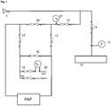
- Such a system is for example disclosed in Figures 3 to 4 , and in Figures 5 to 7 , but in either instance the particulate filter is mounted on a support allowing the filter to be exposed to a structural resonance frequency by means of vibration generating means within the system and the filter being airtight connected at either end to a tubing system with air flow means for generating a pressure or pressurized air flow into said filter characterized in that the tubing system with air flow means comprises valves at either end of the particulate filter by means both the orientation and the pressure inside the filter can be regulated.
- valves ( 16 ) and ( 16' ) and valves ( 17 ) and ( 17' ) allow to control the direction of the pressurized air onto the particulate filter.
- valves ( 18 ) and ( 19 ) at the exit branch the pressure on the filter can be controlled.
- valves ( 17 ) and ( 17' ) are closed and valves ( 16 ) and ( 16' ) are open with valves ( 18 ) and ( 19 ) at the exit being closed.
- valve ( 16 ) the pressurized air will pass via valve ( 16 ) towards one end of the FAP (left side in the schematic representation) and evacuate through valve ( 16' ) towards closed exit valves ( 18 ) and ( 19 ) with pressure build up over the filter.
- valves ( 16 ) and ( 16' ) are closed and valves ( 17 ) and ( 17' ) as well as exit valve ( 19 ).
- the pressurized air will pass via valve ( 17 ) towards the opposite end of the FAP (right side in the schematic representation) and evacuate through valve ( 17' ) towards exit valves ( 18 ) and ( 19 ).
- valve ( 18 ) and manometer ( 20 ) are used to measure the clogging of the filter as the differential pressure with the entrance pressure at manometer ( 21 ).
- the exit valve ( 19 ) is open during this second stage of the cleaning process. In the first step this valve and valve ( 18 ) are both closed. As such, in this first step there is no airflow through the FAP, it simply put under pressure and being under pressure the filter is exposed to vibrations by the vibration motors. In the second step the vibrations are shut by closing vibration motor valve ( 14 ).
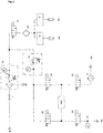
- FIG. 2 An alternative representation of the valves at either end of the FAP and as employed in the exemplified embodiment of figures 5 to 7 , is given in figure 2 .
- the branch feeding the vibration motors is actually the same and includes a valve ( 14 ) to control the pressure in the vibration motors ( 10 ).
- the branch feeding the vibration motors further comprises a lubricator ( 23 ) injecting oil in the air of this part of the pneumatic system.
- another valve ( 15 ) allows opening of the second branch of the pneumatic system feeding pressure and/or a pressurized airflow through the Particulate Filter (PF) in the drawing also referred to as FAP.
- PF Particulate Filter
- valves ( 25 ) and ( 25' ) are closed, valve ( 24 ) is open and valve ( 24' ) is closed. As such the pressurized air will pass through valve ( 24 ) towards one end of the FAP (right side in the schematic representation) with pressure build up since valve ( 24' ) is closed.
- valves ( 24 ) and ( 24' ) are closed and valves ( 25 ) and ( 25' ) are opened.
- valve ( 25 ) the pressurized air will pass through valve ( 25 ) towards the other end of the FAP (left side in the schematic representation) flow trough the filter and evacuate via valve ( 25' ) and into the receptacle ( 9 ).
- valve ( 14 ) the vibration motors are operated and put under pressure by opening of valve ( 14 ), to dislodge the particles from the filter.
- the vibration motors are shut by closing valve ( 14 ).
- the holding means to support the particulate filter may include any device or structure capable of supporting the particulate filter in a pressurized condition whilst being exposed to structural resonant frequency vibrations, without hindering the latter and the provision of the aforementioned frequencies thereto.
- the holding means may for example include an annular ring or other structure for frictionally engaging the particulate filter.
- the holding means could simply comprise a surface with an aperture for supporting the particulate filter on a top portion thereof. Such surface may optionally comprise further structure like engagement means, notches, rims and edges for facilitating a relatively fixed position of the particulate filter with respect to the aperture.
- the holding means to support the particulate filter could comprise structural elements engaging the particulate filter in a gripping engagement.
- any alternative structure for facilitating a relatively fixed position of the filter with respect to the pressurized air is within the admit of the present invention.
- the filter is lying on a horizontal support (table or frame) with for example straps binding the filter to the support.
- the holding means will further comprise sealing means to provide an airtight seal at either end of the filter.
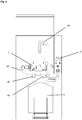
- the systems actually includes holding means (the hood ( 6 ) and the table with lift mechanism ( 8 )) to clamp the DPF in place, wherein said holding means comprise sealing means to proved an airtight pathway through the DPF.
- a hood connected to a flexible rubber sleeve is placed at the top (exhaust side of the DPF) of the DPF.
- the flexible sleeve allows the hood to swivel with a small angle to accommodate tight closure at the airflow entrance for slightly angled exhaust ports.
- the bottom (motor) side of the DPF is placed on a table with an opening, said opening being air tight closed with a rubber ring.
- the size of the ring can be adapted to the opening size of the DPF.
- the sealing means are part of the pneumatic system.
- said sealing means could be adjustable, such as for example a rubber collar for pipe-in-pipe connection, or a sleeve connection.
- a set of adaptors will be available to adjust the opening(s) of the car PF's to fit with the air entry (and air exit) system(s) of the cleaning system (apparatus) of the present invention.
- such an adapter could for example consist of a collar or a sleeve adapter constructed to provide a slide able fit for a given PF exhaust size. Airtight closure at either end of the PF's could again be realized using art known means such as a rubber collar for pipe-in-pipe connection (see Figures 6 and 7 ).
- the present invention is based on imposing in a first stage structural resonance frequencies on the particulate filter whilst kept under pressure in a first direction, followed by a second stage wherein the filter is exposed to an air flow in the opposite direction.
- Said method and device accordingly requires the presence of vibration generating means for imposing a structural resonant frequency of the filter, and means to control the orientation of the pressure on the filter.
- the system comprises at either end of the filter a valve within the pressurized airflow path and a vibration motor connected to the holding means, wherein said valves and motor are connected to a controller with a software signal generator, configured to control the opening and closure of the valves within the pressurized airflow path and to control the output frequency of the vibration motor on the filter.
- the vibration motor is aligned with the longitudinal axis of the filter body element. In another embodiment the vibration motor is aligned at right angles with the longitudinal axis of the filter body element.
- vibration motors on the holding means, in particular pneumatic vibration motors, wherein at least one of said vibration motors is aligned with the longitudinal axis of the filter body element, and wherein at least one of the vibration motors is aligned at right angles with the longitudinal axis of the filter body element.
- the vibration motors must be capable of reaching high vibration frequencies (at least a couple of hundred Hertz) and have a sufficient centrifugal force (at least 1900 Newton). Any vibration motor complying with these characteristics is deployable in the method of the present invention.
- the vibration motor(s) used are pneumatic.
- valves both being within the pressurized airflow, allow controlling the direction of the air pressure on the filter, wherein in the first stage one of the valves will be closed resulting in a pressure build up in the filter in one direction but without an actual airflow going through the filter.
- the structural resonant frequency are at the first resonant frequency, or at harmonic frequencies at multiple values of the principal frequency of the filter.
- Principal frequencies of the filters start at 90 Hz up to about 110 Hz.
- Vibration frequencies of the vibration motor equally start at these values and up to about 1870 Hz.
- the structural resonant frequency is at the first or second harmonic frequency of the principal resonant frequency.
- the vibration frequency is within the range from 180 to 1870 Hz; even more preferable within a frequency range of 350 Hz to 1870 Hz; even more in particular at a frequency of about 1480 Hz.
- the principal frequencies of the filters start at 90 Hz up to about 110 Hz, and consequently vibration frequencies of the vibration motor equally start at about 90 Hz and up to about 1870 Hz; even more preferable at a frequency range of 350 Hz to 1870 Hz; even more in particular at a frequency of about 1480 Hz..
- Pressure inside the filter is increased at pressures of about about 4,5 bar up to about 6 bar. Under these conditions of increased pressure and exposure to a structural resonant frequency, particles are efficiently dislodged from the filter rendering a short first stage step in the method of the invention. Times as short as a couple of minutes are under these conditions indeed sufficient, for example up to 10 minutes, in particular up to 5 minutes are under these conditions sufficient to dislodge the particles from the filter.
- the vibration motor is for example operated at a frequency selected from about 350 Hz; from about 1480 Hz for about 5 minutes whilst the filter is kept at a pressure of 4,5 bar without an airflow through the filter.
- the pressure is increased in the direction of the clean part (exhaust side) of the filter.
- both valves are opened and airflow is generated through the filter in the opposite direction of the pressure in the first stage.
- the sudden drop in pressure enhances the airflow through the filter with a swift, almost instant, and complete removal of the loosened particles from the filter.
- the pressurized air flow in this second stage is at values up to about 2 bar, in particular at about 1,5 bar for up to about 5 minutes, in particular up to about 2 minutes.
- the method of the instant invention is further characterized in that the filter is only exposed to resonant structural energy (vibrations) during the first stage of the cleaning method.
- the filter is not exposed to shock(s) or vibration(s) during the second stage of the cleaning method.
- the filter is stopped during the second stage wherein the dislodged particles are removed by means of an air flow through the filter, in a direction opposite to the pressure applied in the first stage.
- the sudden drop in pressure is in itself sufficient for the dislodged particles to be included in the airflow through the filter, to an extend that the filter is 'quasi' completely regenerated to its original state in a single run.
- the controller for the valves and the vibration generating means can be operated in an open loop or a closed loop scheme.
- the desired frequency values are simply set in the controller depending on the filter to be cleaned. Setting of the desired frequencies may be done by the user through a user interface, but could also follow from the adaptors used in mounting a given DPF in the system. In said instance the adaptors has dimension-depending recognition points that, in interaction with the rest of the cleaning apparatus, allow the controller to recognise the dimensions of the DPF present, and set up the desired frequency values for said DPF.
- this dimension-depending recognition points could consist of contact elements present on the adaptor and dependable on the dimensions of DPF will be unique in their interaction with the contact elements present on the rest of the cleaning apparatus.
- the system further comprises DPF dimension-dependent recognition points.
- initial frequency values for a given DPF are set in a similar way, but in said instance the system further comprises a feedback loop continuously adjusting the frequency settings of the controller based on measurements of the structural frequencies of the filter whilst being cleaned.
- the structural frequencies of the filter are measured by determining the vibration level of the filter, such as for example using an accelerometer ( 11 ) mounted to the outside of the DPF.
- the number and position of the accelerometer(s) is by no way limited and an exemplary configuration is presented in Figure 4 .
- the values from the accelerometer(s) are then fed back to the micro-controller.
- the optimal frequency can be found: varying the frequency over a frequency band around the expected resonance and determining maximum excitation.
- This found (structural) frequency will than become the new (structural) driving frequency.
- This method may have better results than open loop, as the resonant properties can fluctuate a bit, due to the level of ash build-up and the like.
- the feedback signal can be used to monitor the level of vibration to prevent damage or for diagnostic purposes.
- the present invention provides a method for cleaning a particulate filter, said method including the measurement of the vibration level of the filter. Consequently, in a further aspect the present invention provides a system for cleaning a particulate filter, said system comprising means to measure the vibration level of the filter.
- the cleaning system of the present invention may further comprise collection means, such as an ash receptacle ( 9 ) for the particles being released from the particulate filter whilst being processed.
- collection means such as an ash receptacle ( 9 ) for the particles being released from the particulate filter whilst being processed.
- the vibration dislodges the particles of the filter and blowing evacuates. It was not necessary to blow air during the phase of vibration.
Claims (9)
- Procédé en deux étapes pour le nettoyage d'un filtre à particules (7), ledit procédé comprenant :- une première étape soumettant le filtre à particules (7) à une fréquence de résonance structurelle sous pression d'air accrue, étant entendu que ladite pression d'air est augmentée en direction de la partie propre dudit filtre ; et- une deuxième étape soumettant le filtre à particules (7) à un flux d'air en direction de la partie souillée dudit filtre (7).
caractérisé en ce qu'il n'y a pas de flux d'air à travers le filtre à particules (7) lors de la première étape, et en ce que la pression d'air dans le filtre est montée à un niveau situé approximativement entre 4,5 bars et 6,0 bars. - Procédé selon la revendication 1, dans lequel les fréquences de résonance structurelle sont soumises au filtre (7) au moyen d'un moteur vibrateur (10), plus particulièrement un moteur vibrateur pneumatique.
- Procédé selon la revendication 2, dans lequel il y a au moins deux moteurs vibrateurs (10), plus particulièrement des moteurs vibrateurs pneumatiques, étant entendu qu'au moins un desdits moteurs vibrateurs est dans l'alignement de l'axe longitudinal du corps du filtre (7), et étant entendu qu'au moins un des moteurs vibrateurs (10) est aligné à angle droit par rapport à l'axe longitudinal du corps du filtre.
- Procédé selon l'une ou l'autre des revendications 2 et 3, dans lequel les moteurs vibrateurs (10) vibrent à une fréquence de vibration située dans la plage de 90 à 1870 Hz, plus particulièrement à une fréquence de 350 Hz.
- Procédé selon l'une quelconque des revendications 1 à 4, dans lequel le flux d'air est un flux d'air comprimé à un niveau pouvant atteindre une valeur d'environ 2 bars, plus particulièrement à un niveau d'environ 1,5 bar.
- Procédé selon l'une quelconque des revendications 1 à 5, dans lequel le filtre à particules (7) est un filtre à particules pour moteur diesel (DPF) ou un filtre à particules pour moteur essence (GPF), plus particulièrement un DPF pour voiture ou un GPF pour voiture.
- Procédé selon la revendication 6, dans lequel le filtre (7) est orienté à la verticale, la partie souillée vers le bas.
- Système de nettoyage d'un filtre à particules (7), fonctionnant suivant un procédé en deux étapes selon l'une quelconque des revendications 1 à 9, ledit système comprenant :- un dispositif de retenue (6, 8) pour maintenir un filtre à particules ;- un dispositif de génération de vibrations (10) pour soumettre le filtre à une fréquence de résonance structurelle au cours de la première étape du procédé en deux étapes- un dispositif de production de flux d'air (1) pour générer une pression au cours de la première étape du procédé en deux étapes décrit dans la revendication 1 ou un flux d'air comprimé dans ledit filtre (7) au cours de la deuxième étape du procédé en deux étapes ;- un dispositif d'étanchéification (28, 29) destiné à fournir une fermeture hermétique à l'une ou l'autre des extrémités du filtre (7) ; et étant entendu que ledit système se caractérise en ce qu'il comprend deux paires de soupapes à action rapide (16, 16' et 17, 17' ou 24, 24' et 25, 25') à l'une ou l'autre des extrémités du filtre à particules, lesdites soupapes s'ouvrant et/ou se fermant, permettant ainsi de réguler à la fois l'orientation du flux d'air et la pression à l'intérieur du filtre.
- Système selon la revendication 9, dans lequel le dispositif de génération de vibrations (10) inclut un moteur vibrateur raccordé au dispositif de retenue (6, 8).
Priority Applications (2)
| Application Number | Priority Date | Filing Date | Title |
|---|---|---|---|
| PL17704026T PL3420207T3 (pl) | 2016-02-24 | 2017-02-14 | Czyszczenie filtra |
| EP19210243.2A EP3628833B1 (fr) | 2016-02-24 | 2017-02-14 | Nettoyage de filtre |
Applications Claiming Priority (2)
| Application Number | Priority Date | Filing Date | Title |
|---|---|---|---|
| BE2016/5130A BE1023902B1 (fr) | 2016-02-24 | 2016-02-24 | Nettoyage des filtres |
| PCT/EP2017/053201 WO2017144301A1 (fr) | 2016-02-24 | 2017-02-14 | Nettoyage de filtre |
Related Child Applications (2)
| Application Number | Title | Priority Date | Filing Date |
|---|---|---|---|
| EP19210243.2A Division EP3628833B1 (fr) | 2016-02-24 | 2017-02-14 | Nettoyage de filtre |
| EP19210243.2A Division-Into EP3628833B1 (fr) | 2016-02-24 | 2017-02-14 | Nettoyage de filtre |
Publications (2)
| Publication Number | Publication Date |
|---|---|
| EP3420207A1 EP3420207A1 (fr) | 2019-01-02 |
| EP3420207B1 true EP3420207B1 (fr) | 2020-03-04 |
Family
ID=55696808
Family Applications (2)
| Application Number | Title | Priority Date | Filing Date |
|---|---|---|---|
| EP19210243.2A Active EP3628833B1 (fr) | 2016-02-24 | 2017-02-14 | Nettoyage de filtre |
| EP17704026.8A Active EP3420207B1 (fr) | 2016-02-24 | 2017-02-14 | Nettoyage de filtre |
Family Applications Before (1)
| Application Number | Title | Priority Date | Filing Date |
|---|---|---|---|
| EP19210243.2A Active EP3628833B1 (fr) | 2016-02-24 | 2017-02-14 | Nettoyage de filtre |
Country Status (8)
| Country | Link |
|---|---|
| US (1) | US10617988B2 (fr) |
| EP (2) | EP3628833B1 (fr) |
| BE (1) | BE1023902B1 (fr) |
| CA (1) | CA3010330C (fr) |
| ES (1) | ES2781304T3 (fr) |
| HU (1) | HUE050389T2 (fr) |
| PL (1) | PL3420207T3 (fr) |
| WO (1) | WO2017144301A1 (fr) |
Families Citing this family (6)
| Publication number | Priority date | Publication date | Assignee | Title |
|---|---|---|---|---|
| CN111561373B (zh) | 2019-02-14 | 2023-01-03 | 康明斯有限公司 | 用于清洁颗粒过滤器的系统和方法 |
| CN110354593A (zh) * | 2019-06-27 | 2019-10-22 | 三一重机有限公司 | 一种自清洁除尘装置及车辆 |
| CN111375601B (zh) * | 2020-03-06 | 2021-03-26 | 一汽解放汽车有限公司 | 一种dpf清灰装置及清灰方法 |
| CN113769484A (zh) * | 2021-09-18 | 2021-12-10 | 一汽解放汽车有限公司 | Dpf载体再生单元及再生方法 |
| CN113941548B (zh) * | 2021-09-30 | 2023-04-28 | 东风商用车有限公司 | 一种dpf清灰系统及其效果检测方法 |
| DE102022102952A1 (de) | 2022-02-09 | 2023-08-10 | Audi Aktiengesellschaft | Verfahren zur Reinigung eines verschmutzten Luftfilters einer Lüftungseinrichtung eines Kraftfahrzeugs, Reinigungseinrichtung zum Reinigen eines verschmutzten Luftfilters einer Lüftungseinrichtung eines Kraftfahrzeugs |
Family Cites Families (9)
| Publication number | Priority date | Publication date | Assignee | Title |
|---|---|---|---|---|
| US4704144A (en) * | 1986-02-24 | 1987-11-03 | Donaldson Company, Inc. | Air filtering apparatus |
| JPH08177462A (ja) * | 1994-12-22 | 1996-07-09 | Ngk Insulators Ltd | 集塵装置 |
| FR2810072B1 (fr) | 2000-06-08 | 2004-07-16 | Peugeot Citroen Automobiles Sa | Vehicule automobile comportant un filtre a particules a l'interieur du compartiment moteur et procede et installation de nettoyage du filtre a particules |
| DE102004029640A1 (de) | 2004-06-18 | 2006-01-12 | Ernst-Friedhelm Barten | Verfahren zum Reinigen eines Rußfilters |
| US7468085B2 (en) | 2005-12-19 | 2008-12-23 | Caterpillar Inc. | System and method for cleaning a filter |
| US7767031B2 (en) * | 2007-08-13 | 2010-08-03 | International Truck Intellectual Property Company, Llc | Diesel particulate filter cleaning apparatus and method |
| WO2011056477A2 (fr) | 2009-10-26 | 2011-05-12 | Zhe Lu | Méthodes de traitement de maladies associées à l'inflammation et au stress oxydatif |
| US8568536B2 (en) | 2009-12-18 | 2013-10-29 | Caterpillar Inc. | Filter cleaning tool and method |
| EP2579998B1 (fr) | 2010-06-09 | 2019-02-20 | Filter Sensing Technologies, Inc. | Procédé et système pour éliminer le rétentat des filtres |
-
2016
- 2016-02-24 BE BE2016/5130A patent/BE1023902B1/fr not_active IP Right Cessation
-
2017
- 2017-02-14 WO PCT/EP2017/053201 patent/WO2017144301A1/fr active Application Filing
- 2017-02-14 EP EP19210243.2A patent/EP3628833B1/fr active Active
- 2017-02-14 EP EP17704026.8A patent/EP3420207B1/fr active Active
- 2017-02-14 CA CA3010330A patent/CA3010330C/fr active Active
- 2017-02-14 HU HUE17704026A patent/HUE050389T2/hu unknown
- 2017-02-14 US US16/078,805 patent/US10617988B2/en active Active
- 2017-02-14 PL PL17704026T patent/PL3420207T3/pl unknown
- 2017-02-14 ES ES17704026T patent/ES2781304T3/es active Active
Non-Patent Citations (1)
| Title |
|---|
| None * |
Also Published As
| Publication number | Publication date |
|---|---|
| BE1023902B1 (fr) | 2017-09-08 |
| CA3010330C (fr) | 2019-06-11 |
| BE1023902A1 (fr) | 2017-09-07 |
| EP3420207A1 (fr) | 2019-01-02 |
| CA3010330A1 (fr) | 2017-08-31 |
| HUE050389T2 (hu) | 2020-12-28 |
| US20190291036A1 (en) | 2019-09-26 |
| EP3628833A1 (fr) | 2020-04-01 |
| ES2781304T3 (es) | 2020-09-01 |
| WO2017144301A1 (fr) | 2017-08-31 |
| PL3420207T3 (pl) | 2020-06-29 |
| EP3628833B1 (fr) | 2021-05-12 |
| US10617988B2 (en) | 2020-04-14 |
Similar Documents
| Publication | Publication Date | Title |
|---|---|---|
| EP3420207B1 (fr) | Nettoyage de filtre | |
| US9309841B2 (en) | Self-cleaning air filter | |
| JP6138041B2 (ja) | フィルターからろ過残渣を除去する方法及びシステム | |
| US7384455B2 (en) | Filter service system and method | |
| US7410521B2 (en) | Filter service system and method | |
| US7468085B2 (en) | System and method for cleaning a filter | |
| US20130239802A1 (en) | Self-cleaning air filter | |
| KR102063982B1 (ko) | 자동차의 매연저감장치용 세척장치 | |
| KR20180102536A (ko) | 디젤 배기 미립자 수집기용 청소 시스템 | |
| US20060070360A1 (en) | Filter service system and method | |
| KR102139147B1 (ko) | 여과 집진기의 모니터링 시스템 | |
| US20090044375A1 (en) | Diesel particulate filter cleaning apparatus and method | |
| JP5896254B2 (ja) | 粒子フィルタを洗浄するための方法及び構成 | |
| US6129095A (en) | Process for removing dust deposits from ductwork | |
| JP5776632B2 (ja) | エアフィルタ再生方法及びエアフィルタ再生装置 | |
| JP6381086B1 (ja) | 捕集フィルタの洗浄方法 | |
| KR100460666B1 (ko) | 집진기의 탈진방법 및 장치 | |
| GB2125314A (en) | Method of and apparatus for cleaning fabrics | |
| JPH0523515A (ja) | 集じん装置 | |
| JPH08192019A (ja) | 逆洗機構付濾過装置 | |
| US9023135B1 (en) | Self-cleaning air filtration system | |
| KR102236527B1 (ko) | 중소형설비용 여과집진기 폐색방지를 위한 어쿠스틱 블로워 | |
| RU2818476C1 (ru) | Золоулавливающая система | |
| RU79252U1 (ru) | Мокрый пылеуловитель | |
| RU2588326C2 (ru) | Способ и система для очистки сажевого фильтра |
Legal Events
| Date | Code | Title | Description |
|---|---|---|---|
| STAA | Information on the status of an ep patent application or granted ep patent |
Free format text: STATUS: UNKNOWN |
|
| STAA | Information on the status of an ep patent application or granted ep patent |
Free format text: STATUS: THE INTERNATIONAL PUBLICATION HAS BEEN MADE |
|
| PUAI | Public reference made under article 153(3) epc to a published international application that has entered the european phase |
Free format text: ORIGINAL CODE: 0009012 |
|
| STAA | Information on the status of an ep patent application or granted ep patent |
Free format text: STATUS: REQUEST FOR EXAMINATION WAS MADE |
|
| 17P | Request for examination filed |
Effective date: 20180720 |
|
| AK | Designated contracting states |
Kind code of ref document: A1 Designated state(s): AL AT BE BG CH CY CZ DE DK EE ES FI FR GB GR HR HU IE IS IT LI LT LU LV MC MK MT NL NO PL PT RO RS SE SI SK SM TR |
|
| AX | Request for extension of the european patent |
Extension state: BA ME |
|
| RIN1 | Information on inventor provided before grant (corrected) |
Inventor name: LUDIK, LASZLO |
|
| DAV | Request for validation of the european patent (deleted) | ||
| DAX | Request for extension of the european patent (deleted) | ||
| GRAP | Despatch of communication of intention to grant a patent |
Free format text: ORIGINAL CODE: EPIDOSNIGR1 |
|
| STAA | Information on the status of an ep patent application or granted ep patent |
Free format text: STATUS: GRANT OF PATENT IS INTENDED |
|
| INTG | Intention to grant announced |
Effective date: 20190813 |
|
| GRAS | Grant fee paid |
Free format text: ORIGINAL CODE: EPIDOSNIGR3 |
|
| GRAJ | Information related to disapproval of communication of intention to grant by the applicant or resumption of examination proceedings by the epo deleted |
Free format text: ORIGINAL CODE: EPIDOSDIGR1 |
|
| GRAL | Information related to payment of fee for publishing/printing deleted |
Free format text: ORIGINAL CODE: EPIDOSDIGR3 |
|
| STAA | Information on the status of an ep patent application or granted ep patent |
Free format text: STATUS: REQUEST FOR EXAMINATION WAS MADE |
|
| GRAJ | Information related to disapproval of communication of intention to grant by the applicant or resumption of examination proceedings by the epo deleted |
Free format text: ORIGINAL CODE: EPIDOSDIGR1 |
|
| GRAL | Information related to payment of fee for publishing/printing deleted |
Free format text: ORIGINAL CODE: EPIDOSDIGR3 |
|
| GRAR | Information related to intention to grant a patent recorded |
Free format text: ORIGINAL CODE: EPIDOSNIGR71 |
|
| STAA | Information on the status of an ep patent application or granted ep patent |
Free format text: STATUS: GRANT OF PATENT IS INTENDED |
|
| GRAA | (expected) grant |
Free format text: ORIGINAL CODE: 0009210 |
|
| STAA | Information on the status of an ep patent application or granted ep patent |
Free format text: STATUS: THE PATENT HAS BEEN GRANTED |
|
| INTC | Intention to grant announced (deleted) | ||
| AK | Designated contracting states |
Kind code of ref document: B1 Designated state(s): AL AT BE BG CH CY CZ DE DK EE ES FI FR GB GR HR HU IE IS IT LI LT LU LV MC MK MT NL NO PL PT RO RS SE SI SK SM TR |
|
| INTG | Intention to grant announced |
Effective date: 20200127 |
|
| REG | Reference to a national code |
Ref country code: GB Ref legal event code: FG4D |
|
| REG | Reference to a national code |
Ref country code: CH Ref legal event code: EP |
|
| REG | Reference to a national code |
Ref country code: AT Ref legal event code: REF Ref document number: 1240608 Country of ref document: AT Kind code of ref document: T Effective date: 20200315 |
|
| REG | Reference to a national code |
Ref country code: DE Ref legal event code: R096 Ref document number: 602017012581 Country of ref document: DE |
|
| REG | Reference to a national code |
Ref country code: IE Ref legal event code: FG4D |
|
| REG | Reference to a national code |
Ref country code: NL Ref legal event code: FP |
|
| REG | Reference to a national code |
Ref country code: SK Ref legal event code: T3 Ref document number: E 33978 Country of ref document: SK |
|
| PG25 | Lapsed in a contracting state [announced via postgrant information from national office to epo] |
Ref country code: RS Free format text: LAPSE BECAUSE OF FAILURE TO SUBMIT A TRANSLATION OF THE DESCRIPTION OR TO PAY THE FEE WITHIN THE PRESCRIBED TIME-LIMIT Effective date: 20200304 Ref country code: FI Free format text: LAPSE BECAUSE OF FAILURE TO SUBMIT A TRANSLATION OF THE DESCRIPTION OR TO PAY THE FEE WITHIN THE PRESCRIBED TIME-LIMIT Effective date: 20200304 Ref country code: NO Free format text: LAPSE BECAUSE OF FAILURE TO SUBMIT A TRANSLATION OF THE DESCRIPTION OR TO PAY THE FEE WITHIN THE PRESCRIBED TIME-LIMIT Effective date: 20200604 |
|
| PG25 | Lapsed in a contracting state [announced via postgrant information from national office to epo] |
Ref country code: LV Free format text: LAPSE BECAUSE OF FAILURE TO SUBMIT A TRANSLATION OF THE DESCRIPTION OR TO PAY THE FEE WITHIN THE PRESCRIBED TIME-LIMIT Effective date: 20200304 Ref country code: SE Free format text: LAPSE BECAUSE OF FAILURE TO SUBMIT A TRANSLATION OF THE DESCRIPTION OR TO PAY THE FEE WITHIN THE PRESCRIBED TIME-LIMIT Effective date: 20200304 Ref country code: BG Free format text: LAPSE BECAUSE OF FAILURE TO SUBMIT A TRANSLATION OF THE DESCRIPTION OR TO PAY THE FEE WITHIN THE PRESCRIBED TIME-LIMIT Effective date: 20200604 Ref country code: HR Free format text: LAPSE BECAUSE OF FAILURE TO SUBMIT A TRANSLATION OF THE DESCRIPTION OR TO PAY THE FEE WITHIN THE PRESCRIBED TIME-LIMIT Effective date: 20200304 Ref country code: GR Free format text: LAPSE BECAUSE OF FAILURE TO SUBMIT A TRANSLATION OF THE DESCRIPTION OR TO PAY THE FEE WITHIN THE PRESCRIBED TIME-LIMIT Effective date: 20200605 |
|
| REG | Reference to a national code |
Ref country code: ES Ref legal event code: FG2A Ref document number: 2781304 Country of ref document: ES Kind code of ref document: T3 Effective date: 20200901 |
|
| REG | Reference to a national code |
Ref country code: LT Ref legal event code: MG4D |
|
| PG25 | Lapsed in a contracting state [announced via postgrant information from national office to epo] |
Ref country code: RO Free format text: LAPSE BECAUSE OF FAILURE TO SUBMIT A TRANSLATION OF THE DESCRIPTION OR TO PAY THE FEE WITHIN THE PRESCRIBED TIME-LIMIT Effective date: 20200304 Ref country code: IS Free format text: LAPSE BECAUSE OF FAILURE TO SUBMIT A TRANSLATION OF THE DESCRIPTION OR TO PAY THE FEE WITHIN THE PRESCRIBED TIME-LIMIT Effective date: 20200704 Ref country code: CZ Free format text: LAPSE BECAUSE OF FAILURE TO SUBMIT A TRANSLATION OF THE DESCRIPTION OR TO PAY THE FEE WITHIN THE PRESCRIBED TIME-LIMIT Effective date: 20200304 Ref country code: PT Free format text: LAPSE BECAUSE OF FAILURE TO SUBMIT A TRANSLATION OF THE DESCRIPTION OR TO PAY THE FEE WITHIN THE PRESCRIBED TIME-LIMIT Effective date: 20200729 Ref country code: LT Free format text: LAPSE BECAUSE OF FAILURE TO SUBMIT A TRANSLATION OF THE DESCRIPTION OR TO PAY THE FEE WITHIN THE PRESCRIBED TIME-LIMIT Effective date: 20200304 Ref country code: EE Free format text: LAPSE BECAUSE OF FAILURE TO SUBMIT A TRANSLATION OF THE DESCRIPTION OR TO PAY THE FEE WITHIN THE PRESCRIBED TIME-LIMIT Effective date: 20200304 Ref country code: SM Free format text: LAPSE BECAUSE OF FAILURE TO SUBMIT A TRANSLATION OF THE DESCRIPTION OR TO PAY THE FEE WITHIN THE PRESCRIBED TIME-LIMIT Effective date: 20200304 |
|
| REG | Reference to a national code |
Ref country code: DE Ref legal event code: R097 Ref document number: 602017012581 Country of ref document: DE |
|
| REG | Reference to a national code |
Ref country code: HU Ref legal event code: AG4A Ref document number: E050389 Country of ref document: HU |
|
| PLBE | No opposition filed within time limit |
Free format text: ORIGINAL CODE: 0009261 |
|
| STAA | Information on the status of an ep patent application or granted ep patent |
Free format text: STATUS: NO OPPOSITION FILED WITHIN TIME LIMIT |
|
| PG25 | Lapsed in a contracting state [announced via postgrant information from national office to epo] |
Ref country code: DK Free format text: LAPSE BECAUSE OF FAILURE TO SUBMIT A TRANSLATION OF THE DESCRIPTION OR TO PAY THE FEE WITHIN THE PRESCRIBED TIME-LIMIT Effective date: 20200304 |
|
| 26N | No opposition filed |
Effective date: 20201207 |
|
| PG25 | Lapsed in a contracting state [announced via postgrant information from national office to epo] |
Ref country code: SI Free format text: LAPSE BECAUSE OF FAILURE TO SUBMIT A TRANSLATION OF THE DESCRIPTION OR TO PAY THE FEE WITHIN THE PRESCRIBED TIME-LIMIT Effective date: 20200304 |
|
| PG25 | Lapsed in a contracting state [announced via postgrant information from national office to epo] |
Ref country code: MC Free format text: LAPSE BECAUSE OF FAILURE TO SUBMIT A TRANSLATION OF THE DESCRIPTION OR TO PAY THE FEE WITHIN THE PRESCRIBED TIME-LIMIT Effective date: 20200304 |
|
| PG25 | Lapsed in a contracting state [announced via postgrant information from national office to epo] |
Ref country code: LI Free format text: LAPSE BECAUSE OF NON-PAYMENT OF DUE FEES Effective date: 20210228 Ref country code: CH Free format text: LAPSE BECAUSE OF NON-PAYMENT OF DUE FEES Effective date: 20210228 |
|
| PGFP | Annual fee paid to national office [announced via postgrant information from national office to epo] |
Ref country code: HU Payment date: 20220213 Year of fee payment: 6 Ref country code: GB Payment date: 20220223 Year of fee payment: 6 Ref country code: AT Payment date: 20220217 Year of fee payment: 6 |
|
| PGFP | Annual fee paid to national office [announced via postgrant information from national office to epo] |
Ref country code: SK Payment date: 20220214 Year of fee payment: 6 Ref country code: PL Payment date: 20220124 Year of fee payment: 6 Ref country code: NL Payment date: 20220216 Year of fee payment: 6 Ref country code: LU Payment date: 20220216 Year of fee payment: 6 |
|
| PGFP | Annual fee paid to national office [announced via postgrant information from national office to epo] |
Ref country code: IE Payment date: 20220515 Year of fee payment: 6 |
|
| PGFP | Annual fee paid to national office [announced via postgrant information from national office to epo] |
Ref country code: FR Payment date: 20230221 Year of fee payment: 7 |
|
| PGFP | Annual fee paid to national office [announced via postgrant information from national office to epo] |
Ref country code: IT Payment date: 20230223 Year of fee payment: 7 Ref country code: BE Payment date: 20230216 Year of fee payment: 7 |
|
| PG25 | Lapsed in a contracting state [announced via postgrant information from national office to epo] |
Ref country code: CY Free format text: LAPSE BECAUSE OF FAILURE TO SUBMIT A TRANSLATION OF THE DESCRIPTION OR TO PAY THE FEE WITHIN THE PRESCRIBED TIME-LIMIT Effective date: 20200304 |
|
| PGFP | Annual fee paid to national office [announced via postgrant information from national office to epo] |
Ref country code: ES Payment date: 20230427 Year of fee payment: 7 |
|
| REG | Reference to a national code |
Ref country code: SK Ref legal event code: MM4A Ref document number: E 33978 Country of ref document: SK Effective date: 20230214 |
|
| REG | Reference to a national code |
Ref country code: NL Ref legal event code: MM Effective date: 20230301 |
|
| REG | Reference to a national code |
Ref country code: AT Ref legal event code: MM01 Ref document number: 1240608 Country of ref document: AT Kind code of ref document: T Effective date: 20230214 |
|
| GBPC | Gb: european patent ceased through non-payment of renewal fee |
Effective date: 20230214 |
|
| PG25 | Lapsed in a contracting state [announced via postgrant information from national office to epo] |
Ref country code: LU Free format text: LAPSE BECAUSE OF NON-PAYMENT OF DUE FEES Effective date: 20230214 Ref country code: AT Free format text: LAPSE BECAUSE OF NON-PAYMENT OF DUE FEES Effective date: 20230214 |
|
| PG25 | Lapsed in a contracting state [announced via postgrant information from national office to epo] |
Ref country code: SK Free format text: LAPSE BECAUSE OF NON-PAYMENT OF DUE FEES Effective date: 20230214 Ref country code: NL Free format text: LAPSE BECAUSE OF NON-PAYMENT OF DUE FEES Effective date: 20230301 Ref country code: HU Free format text: LAPSE BECAUSE OF NON-PAYMENT OF DUE FEES Effective date: 20230215 |
|
| REG | Reference to a national code |
Ref country code: IE Ref legal event code: MM4A |
|
| PG25 | Lapsed in a contracting state [announced via postgrant information from national office to epo] |
Ref country code: GB Free format text: LAPSE BECAUSE OF NON-PAYMENT OF DUE FEES Effective date: 20230214 |
|
| PG25 | Lapsed in a contracting state [announced via postgrant information from national office to epo] |
Ref country code: IE Free format text: LAPSE BECAUSE OF NON-PAYMENT OF DUE FEES Effective date: 20230214 Ref country code: GB Free format text: LAPSE BECAUSE OF NON-PAYMENT OF DUE FEES Effective date: 20230214 |
|
| PGFP | Annual fee paid to national office [announced via postgrant information from national office to epo] |
Ref country code: ES Payment date: 20240301 Year of fee payment: 8 |
|
| PG25 | Lapsed in a contracting state [announced via postgrant information from national office to epo] |
Ref country code: MK Free format text: LAPSE BECAUSE OF FAILURE TO SUBMIT A TRANSLATION OF THE DESCRIPTION OR TO PAY THE FEE WITHIN THE PRESCRIBED TIME-LIMIT Effective date: 20200304 |
|
| PGFP | Annual fee paid to national office [announced via postgrant information from national office to epo] |
Ref country code: DE Payment date: 20240228 Year of fee payment: 8 |