EP3420150B1 - Siebvorrichtung - Google Patents
Siebvorrichtung Download PDFInfo
- Publication number
- EP3420150B1 EP3420150B1 EP17705877.3A EP17705877A EP3420150B1 EP 3420150 B1 EP3420150 B1 EP 3420150B1 EP 17705877 A EP17705877 A EP 17705877A EP 3420150 B1 EP3420150 B1 EP 3420150B1
- Authority
- EP
- European Patent Office
- Prior art keywords
- screening device
- sieve
- drive
- wastewater
- grate
- Prior art date
- Legal status (The legal status is an assumption and is not a legal conclusion. Google has not performed a legal analysis and makes no representation as to the accuracy of the status listed.)
- Active
Links
Images


Classifications
-
- E—FIXED CONSTRUCTIONS
- E03—WATER SUPPLY; SEWERAGE
- E03F—SEWERS; CESSPOOLS
- E03F5/00—Sewerage structures
- E03F5/14—Devices for separating liquid or solid substances from sewage, e.g. sand or sludge traps, rakes or grates
-
- B—PERFORMING OPERATIONS; TRANSPORTING
- B01—PHYSICAL OR CHEMICAL PROCESSES OR APPARATUS IN GENERAL
- B01D—SEPARATION
- B01D29/00—Filters with filtering elements stationary during filtration, e.g. pressure or suction filters, not covered by groups B01D24/00 - B01D27/00; Filtering elements therefor
- B01D29/11—Filters with filtering elements stationary during filtration, e.g. pressure or suction filters, not covered by groups B01D24/00 - B01D27/00; Filtering elements therefor with bag, cage, hose, tube, sleeve or like filtering elements
- B01D29/31—Self-supporting filtering elements
- B01D29/35—Self-supporting filtering elements arranged for outward flow filtration
-
- B—PERFORMING OPERATIONS; TRANSPORTING
- B01—PHYSICAL OR CHEMICAL PROCESSES OR APPARATUS IN GENERAL
- B01D—SEPARATION
- B01D29/00—Filters with filtering elements stationary during filtration, e.g. pressure or suction filters, not covered by groups B01D24/00 - B01D27/00; Filtering elements therefor
- B01D29/44—Edge filtering elements, i.e. using contiguous impervious surfaces
- B01D29/445—Bar screens
-
- B—PERFORMING OPERATIONS; TRANSPORTING
- B01—PHYSICAL OR CHEMICAL PROCESSES OR APPARATUS IN GENERAL
- B01D—SEPARATION
- B01D29/00—Filters with filtering elements stationary during filtration, e.g. pressure or suction filters, not covered by groups B01D24/00 - B01D27/00; Filtering elements therefor
- B01D29/62—Regenerating the filter material in the filter
- B01D29/64—Regenerating the filter material in the filter by scrapers, brushes, nozzles, or the like, acting on the cake side of the filtering element
- B01D29/6469—Regenerating the filter material in the filter by scrapers, brushes, nozzles, or the like, acting on the cake side of the filtering element scrapers
- B01D29/6484—Regenerating the filter material in the filter by scrapers, brushes, nozzles, or the like, acting on the cake side of the filtering element scrapers with a translatory movement with respect to the filtering element
-
- E—FIXED CONSTRUCTIONS
- E02—HYDRAULIC ENGINEERING; FOUNDATIONS; SOIL SHIFTING
- E02B—HYDRAULIC ENGINEERING
- E02B8/00—Details of barrages or weirs ; Energy dissipating devices carried by lock or dry-dock gates
- E02B8/02—Sediment base gates; Sand sluices; Structures for retaining arresting waterborne material
- E02B8/023—Arresting devices for waterborne materials
- E02B8/026—Cleaning devices
Definitions
- the present invention relates to a screening device for separating and removing contaminants from waste water with two endless and spaced-apart drive means, the drive means each being guided in an orbit with at least one drive wheel, with a stationary sieve grate which has a plurality of grate bars arranged adjacent to one another Has separation of contaminants from the waste water, and with a plurality of clearing elements connected to the drive means for removing the contaminants separated from the sieve grate from the sieve grate.
- Such screening devices are well known from the prior art and are used, for example, to remove coarse screenings (wood, stones, etc.) from waste water flowing in a sewer.
- a good degree of separation and thus the efficiency of the screening device depend here in particular on the flow conditions of the sewer and the geometry of the screening device.
- the sieve grids of known sieve devices extend transversely to the flow direction of the waste water reaching the sieve device.
- the incoming wastewater flows against the sieve grate from the front, the wastewater passing through the sieve grate without major deflections, thus essentially maintaining its direction of flow.
- Corresponding screening devices are for example in the WO 03/059487 A1 and the CH 677 001 A5 shown.
- the degree of separation can be increased by reducing the spacing of the grate bars of the sieve grate become.
- the object of the present invention is therefore to provide an efficient screening device which advantageously differs from the prior art.
- a sieve device for separating and removing impurities from waste water.
- the screening device comprises at least two endless and spaced apart drive means.
- the drive means are each guided with at least one drive wheel in an orbit, each drive means being primarily connected with the aid of a plurality of drive wheels.
- the sieve device furthermore has a stationary sieve grate with a plurality of grate bars arranged adjacent to one another for separating contaminants from the waste water, the sieve grate forming a sieve surface against which the sewage device flows during operation.
- the sieve grate forms a stationary sieve surface, which is in the intended installation position of the sieve device (ie capable that it takes after installation in a sewer) extends essentially in the direction of flow of the sewage reaching the screening device.
- the direction of flow is the direction that the waste water has immediately before reaching the screening device or shortly before entering the screening device.
- the width of the sewer runs transverse to the flow direction of the sewage.
- the essence of the invention therefore lies in the fact that the screen surface formed by the screen grid does not, as is customary in the prior art, run at a 90 ° angle to the flow direction mentioned. Rather, the sieve surface in the installed state of the sieve device essentially runs in the direction of flow of the wastewater flowing into the sieve device, so that it is deflected laterally when it flows through the openings of the sieve grate (for this purpose, as will be explained in more detail later, the sieve device preferably has a flow deflection , for example in the form of a baffle, on).
- the screen surface is preferably parallel to the direction of flow, i.e. their horizontal width extends exactly in the flow direction mentioned. Alternatively, deviations of up to 20 ° are also conceivable, since in this case too, the screen surface extends essentially in the flow direction mentioned.
- the drive wheels can be driven by means of a drive of the screening device (for example an electric motor), so that the two drive means mounted by means of the drive wheels move along the orbit when the screening device is in operation.
- the screening device preferably comprises at least two drive wheels which can be rotated about a common axis of rotation, each drive wheel of the drive wheel pair being connected to its own drive means (the axis of rotation in the sense of the present invention is to be understood as the axis around which the respective drive wheel rotates when operating the drive mentioned).
- the screening device preferably comprises a plurality of drive wheel pairs, the Axes of rotation of the individual drive wheel pairs preferably run parallel to one another.
- the drive means are connected to the clearing elements in such a way that they are moved along the orbit together with the drive means as a result of the drive wheels being driven.
- the stationary sieve grate is arranged, in particular between the drive means, in such a way that the clearing elements sweep past it and can remove the impurities.
- the arrangement described makes it possible to choose the width of the sieve grate or its sieve surface running in the flow direction mentioned, with a corresponding adjustment of the length of the clearing elements, since these dimensions run in the flow direction of the sewage reaching the sieve device and thus in the longitudinal direction of the sewer ,
- the width of the screen surface in known screening devices is limited by the width of the sewer.
- the width of the sewer which in the prior art is therefore decisive for the geometry of the entire screening device, no longer acts as a limiting variable in the present invention with regard to the width of the screening surface.
- a high degree of separation and good throughput can now be achieved, for example, by reducing the distance between the grate bars in the flow direction of the waste water and at the same time increasing the number of grate bars.
- the length of the clearing elements which extends essentially parallel to the axis of rotation of the drive wheels, can then be adapted to the width of the sieve grate.
- a part or preferably all of the axes of rotation of the drive wheels guiding the drive means in the installed position of the screening device should be essentially in the flow direction of the one reaching the screening device or be aligned with the wastewater flowing into the screening device.
- the axes of rotation preferably also run in the horizontal direction.
- the orbit of the respective drive means is also preferably in each case in a plane which is oriented essentially transversely to the flow direction mentioned and in particular vertically.
- the screening device comprises a frame with an inlet opening for the waste water.
- the inlet opening is arranged in the intended installation position of the screening device and in relation to the flow direction of the waste water reaching the screening device in front of the screen grate.
- the frame is designed in such a way that the flowing waste water is guided through the inlet opening and to the sieve grate arranged therein.
- the wastewater reaching the screening device is prevented from continuing to flow by the frame itself. However, it can flow into the sieving device through the inlet opening and is directed in a targeted manner to the sieve grate.
- the wastewater can then drain through the grate bars, with the flowed, i.e. H. the contaminants carried by the wastewater are separated on the screen surface.
- the sieve grate need not be formed in one piece, but can consist of several sections, which in turn can be connected to one another or also spaced apart.
- the screen surface does not have to be a coherent surface. Rather, the screen surface can also be composed of several sections, wherein individual sections can also be separated from one another.
- the sieve device On its side opposite the inlet opening, the sieve device advantageously has a storage wall. That through the inlet opening in wastewater flowing into the sieving device and with it the impurities can thereby be diverted in such a way that the wastewater hits the sieve grate and its non-retained component penetrates through the grate bars to the outside.
- the damming wall here preferably runs perpendicular to the direction of flow of the wastewater flowing into the screening device and thus causes a change in the direction of flow of the wastewater.
- the dirt can be separated from the waste water on the grate bars and conveyed upwards in the direction of a discharge point by the surrounding clearing elements.
- the efficiency of the screening device can be positively influenced by such a design, since the wastewater is reliably redirected to the dam wall and forcibly passed through the screen grate.
- the baffle wall in the intended installation position of the screening device runs transversely or obliquely to the direction of flow of the waste water reaching the screening device.
- the sieve device preferably extends over the entire width of the sewer, the dam wall bridging only part of the width of the sewer, so that the sewage can flow through the sieve grate between the dam wall and the canal wall of the sewer.
- the incoming wastewater flows through the inlet opening into the screening device. There it is deflected by the dam wall and finally flows through the sieve grate, in order to finally leave the sieve device again, with impurities from a certain size being retained by the sieve grate.
- the dam wall is arranged in the intended installation position of the screening device in the direction of flow after the inlet opening.
- the contaminated wastewater can flow into the screening device through the inlet opening and be deflected by the dam wall.
- a such an arrangement of the baffle wall in relation to the inlet opening enables the wastewater to be guided specifically within the screening device.
- the sieve grate advantageously extends in the intended installation position of the sieve device and in relation to the flow direction of the waste water reaching the sieve device between the inlet opening of the frame and the baffle.
- the sieve grate forms a drain opening of the frame. Waste water flowing in through the inlet opening and diverted through the dam wall can thus only be discharged through the sieve grate, i.e. H. emerge from the frame or the sieve device through the openings delimited by the grate bars.
- the distance and / or the number of grate bars and thus the width of the sieve grate can be changed, since this dimension is independent of the cross section of the sewer itself.
- the distance between the inlet opening and the baffle wall is preferably 1 to 1.5 times the width of the sieve grate.
- both the inlet opening and the dam wall should connect directly to the sieve grate.
- the sieve grate essentially has a U or V shape with a view of the inlet opening, ie in the direction of flow of the waste water flowing into the sieve device.
- the screen grate extends at least partially along the orbit of the drive means.
- the clearing elements guided in this orbit can hereby be guided along the sieve grate and remove the impurities.
- the effectively usable area of the sieve grate can be made relatively large in a structurally simple manner.
- the legs of the U or V shape can also be of the same length. It is also conceivable that the above Leg parallel. However, the horizontal distance between the legs preferably increases in the vertical direction.
- the sieve grate comprises a sieve trough and two sieve sections adjoining the sieve trough on both sides, the sieve surface of the sieve device being formed by the sieve trough and the mentioned sieve sections.
- the sieve grate is preferably symmetrical.
- the sieve grate can be in one part or in several parts, so that it can be repaired quickly and inexpensively in the event of maintenance.
- the grate area can also be increased as a result, so that the amount of contaminants that can be separated can be significantly increased.
- the screen grate preferably consists of three main components which are connected to one another, namely the screen trough and the screen sections connected to it.
- the two sieve sections advantageously extend at least in sections in a straight line from the sieve trough upwards.
- the first sieve grate section extends from the discharge or from an upper end section of the sieve grate arranged below the discharge down to the sieve pan.
- a chute plate which is preferably formed by at least one plate, is preferably arranged between the upper end section of the sieve grate and the discharge. The contaminants are transported by the grate bars in the direction of the upper end section, and the waste water can escape between the grate bars. The contaminants then reach the area of the chute sheet and are removed from the screening device via the discharge.
- the sieve pan is advantageously arranged in the region of a sewer bottom of the sewer. It is also advantageous if the second sieve grate section extends upwards from the sieve pan. In this way Even with a high wastewater level, it can be guaranteed that the contaminants are reliably removed from the wastewater.
- the drive means are advantageously drive chains, drive belts or drive cables.
- the design of the drive means can be individually adapted to the required properties of the screening device.
- the drive wheels must be adjusted according to the choice of drive means.
- the drive means are each guided on the orbit by means of at least one upper drive wheel.
- the drive means are moved in their orbit by means of a drive (e.g. an electric motor) during operation of the screening device.
- the drive is preferably arranged in the area of the upper drive wheels, so that its sensitive components are protected from moisture.
- the upper drive wheels are located in the area of an upper turning point of the drive means, in which they experience a reversal of direction.
- the screening device can have a further pair of drive wheels arranged below the upper drive wheels, which can be driven indirectly or directly by the drive via the drive means.
- the last-mentioned drive wheel pair is preferably arranged in the vertical direction in the region between the screen trough and the upper drive wheels, particularly preferably between the screen grate and the upper drive wheels.
- a pair of drive wheels can also be arranged in the area of the screen trough, preferably below it.
- the drive means can also be guided in the area of the screen trough by a drive guide, which can be arranged in the area of a sewer bottom of the sewer.
- the drive guide is, for example, by Plastic elements are formed, which are assigned to the drive means and are in contact with them.
- the drive guide can be or comprise a runner or rail.
- the drive means are advantageously arranged one behind the other in the intended installation position of the screening device in the flow direction of the waste water reaching the screening device.
- the clearing elements which are connected to the drive means and essentially arranged between them run essentially parallel to the axis of rotation of the drive wheels and thus in the direction of flow of the waste water flowing into the screening device.
- the Figures 1 and 2 each show a screening device 1 for separating and removing contaminants 2, in particular screenings, from wastewater 3.
- the screening device 1 is integrated in a wastewater channel 4 and comprises a frame 5 via which it is anchored in the wastewater channel 4.
- the frame 5 is z. B. connected to a channel bottom 6 of the sewer 4.
- the waste water 3 can flow into the screening device 1 through an inlet opening 7 of the frame 5.
- the section of the screening device 1 forming the inlet opening 7 is shown in FIG Figure 2 not shown, in order to be able to show the sections lying behind (the inlet opening 7 lying in front of the sheet plane is represented by a dashed line).
- the section is a wall of the frame 5 that runs parallel to the plane of the sheet and that seals with the channel base 6 and the side walls of the waste water channel 4, so that waste water 3 can only flow into the screening device 1 via the inlet opening 7 ( see Figure 1).
- the flow direction X runs in the x direction into the sheet plane.
- the frame 5 On its side opposite the inlet opening 7, the frame 5 has a storage wall 8.
- the drive means 9 are each guided on an orbit 13 with at least one drive wheel 10.
- the guidance here takes place in particular with the aid of an upper drive wheel 10, and preferably also with the aid of a middle drive wheel 11 and / or a drive guide 12 (cf. Fig. 2 and Fig. 3 ) along an orbit 13.
- the drive means 9 are designed as a drive chain, drive belt or drive cables. According to the Choice of the drive means 9, the drive wheels 10, 11 are then designed as a chain wheel, belt wheel or rope wheel.
- the drive guide 12 is preferably a runner or a rail.
- the shown sieve device 1 has a U- or V-shaped sieve grate 14, which is at least partially arranged between the two drive means 9.
- a plurality of clearing elements 15 are arranged between the drive means 9, by means of which the impurities 2 retained by the sieve grate 14 can be removed therefrom.
- the drive wheels 10, 11 can be moved indirectly or directly along a conveying direction F by a drive, not shown, so that the drive means 9 mounted with the aid of the drive wheels 10, 11 move along the orbit 13.
- the drive wheels 10, 11 preferably rotate about an axis of rotation 16 which is in the flow direction X of the Screening device 1 passing sewage 3, which in Figure 1 is defined by the x direction.
- the clearing elements 15 are operatively connected to the drive means 9 such that they are also moved on the orbit 13.
- the clearing elements 15 sweep past the sieve grate 14 and remove the contaminants 2 from it.
- the clearing elements 15 are in particular designed to transport the contaminants 2 upwards in the direction of a discharge 17. From there, the impurities 2 are conveyed, for example, into a container 18.
- a chute plate 29 is also arranged between the discharge 17 and an upper end section 27 of the sieve grate.
- the chute plate 29 extends obliquely upward as an extension of the sieve grate 14 and is designed to be water-impermeable, so that the waste water 3 can only emerge in the area of the waste water channel 4, but not beyond its width.
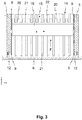
- FIG 3 shows a schematic detail of a side view of the screening device 1 according to the invention in the area of a lower drive guide 12.
- the drive guide 12 is arranged in the frame 5 above the channel base 6.
- the broaching elements 15 extend between the two drive means 9.
- the broaching elements 15 are connected to the drive means 9 so that they move together with them in the conveying direction F.
- Each clearing element 15 preferably comprises a clearing bar 19 with cleaning tines 20 arranged next to one another.
- the clearing elements 15 extend in the flow direction X of the waste water 3.
- the sieve grate 14 has a plurality of grate bars 21 which correspond to the cleaning prongs 20 in such a way that they engage in the openings 22 between the grate bars 21 in order to remove the contaminants 2 (cf. Fig. 1 and Fig. 2 ) to remove.
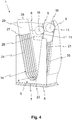
- FIG 4 shows a perspective detail of the screening device 1. For reasons of clarity, the clearing elements 15 are not shown here.
- the drive means 9 are only shown in the left area.
- the sieve grate 14 is U-shaped or V-shaped and is arranged between the inlet opening 7 and the baffle wall 8.
- the baffle 8 also has an emergency overflow 28 so that the waste water 3 can flow out of the screening device 1 from a certain waste water level or if the screening device becomes blocked due to a malfunction due to the emergency overflow 28.
- the sieve grate 14 comprises a sieve pan 23, a first sieve grate section 24 and a second sieve grate section 25.
- the two sieve sections 24, 25 extend on both sides from the sieve pan 23 essentially upwards in a straight line.
- the sieve pan 23 also has grate bars 21 arranged next to one another.
- the first screen grid section 24 extends from the upper end section 27, (cf. Fig. 1 ), up to the sieve pan 23.
- the sieve pan 23 is arranged in the region of the channel base 6.
- the second sieve grid section 24 extends from the sieve pan 23, in particular via the waste water 3 (cf. Fig. 1 ) out, up.
- each section of the screen surface 26 formed by the screen pan 23 and the remaining screen sections 24, 25 runs parallel to the flow direction X.
Landscapes
- Chemical & Material Sciences (AREA)
- Chemical Kinetics & Catalysis (AREA)
- Engineering & Computer Science (AREA)
- Hydrology & Water Resources (AREA)
- Health & Medical Sciences (AREA)
- Life Sciences & Earth Sciences (AREA)
- General Engineering & Computer Science (AREA)
- Public Health (AREA)
- Water Supply & Treatment (AREA)
- Structural Engineering (AREA)
- Civil Engineering (AREA)
- Mechanical Engineering (AREA)
- Sewage (AREA)
- Filtration Of Liquid (AREA)
- Separation Of Solids By Using Liquids Or Pneumatic Power (AREA)
Priority Applications (1)
| Application Number | Priority Date | Filing Date | Title |
|---|---|---|---|
| PL17705877T PL3420150T3 (pl) | 2016-02-23 | 2017-02-17 | Urządzenie sitowe |
Applications Claiming Priority (2)
| Application Number | Priority Date | Filing Date | Title |
|---|---|---|---|
| DE102016103081.3A DE102016103081A1 (de) | 2016-02-23 | 2016-02-23 | Siebvorrichtung |
| PCT/EP2017/053609 WO2017144361A1 (de) | 2016-02-23 | 2017-02-17 | Siebvorrichtung |
Publications (2)
| Publication Number | Publication Date |
|---|---|
| EP3420150A1 EP3420150A1 (de) | 2019-01-02 |
| EP3420150B1 true EP3420150B1 (de) | 2020-01-08 |
Family
ID=58057137
Family Applications (1)
| Application Number | Title | Priority Date | Filing Date |
|---|---|---|---|
| EP17705877.3A Active EP3420150B1 (de) | 2016-02-23 | 2017-02-17 | Siebvorrichtung |
Country Status (8)
| Country | Link |
|---|---|
| US (1) | US10648166B2 (pl) |
| EP (1) | EP3420150B1 (pl) |
| CN (1) | CN108699834B (pl) |
| CA (1) | CA3015424C (pl) |
| DE (1) | DE102016103081A1 (pl) |
| ES (1) | ES2774715T3 (pl) |
| PL (1) | PL3420150T3 (pl) |
| WO (1) | WO2017144361A1 (pl) |
Families Citing this family (7)
| Publication number | Priority date | Publication date | Assignee | Title |
|---|---|---|---|---|
| US11633680B2 (en) * | 2020-07-23 | 2023-04-25 | Parkson Corporation | Bar screen filter apparatus and method |
| CN111962654B (zh) * | 2020-08-14 | 2021-09-14 | 福建省欣硕景观绿化有限公司 | 一种市政雨水泵站及其排渣方法 |
| CN112320870A (zh) * | 2020-10-31 | 2021-02-05 | 江苏诺德环保工程有限公司 | 一种高效回转格栅除污机 |
| CN112459219A (zh) * | 2020-11-16 | 2021-03-09 | 宋亚攀 | 一种用于市政工程的下水管道水流过滤系统 |
| WO2023041147A1 (en) * | 2021-09-15 | 2023-03-23 | Gumis D.O.O. | Separator for hazardous waste material from sanitary wastewater, with a self-cleaning ability |
| FR3131221A1 (fr) * | 2021-12-23 | 2023-06-30 | Pascal CREPET | Dispositif de filtrage autonettoyant |
| PL444636A1 (pl) * | 2023-04-25 | 2024-10-28 | Zygmunt Czekała | Samoczyszcząca zmechanizowana krata, zwłaszcza do oczyszczania ścieków |
Family Cites Families (14)
| Publication number | Priority date | Publication date | Assignee | Title |
|---|---|---|---|---|
| US2291121A (en) * | 1938-11-01 | 1942-07-28 | Jeffrey Mfg Co | Sewage apparatus |
| US3835999A (en) * | 1972-10-18 | 1974-09-17 | Bauer Bros Co | Screen units used for dewatering and classifying the contents of a liquid slurry |
| DE2722063A1 (de) * | 1977-05-16 | 1978-11-23 | Altmeyer | Einrichtung zur behandlung von abwaessern vor eintritt in die biologische reinigung |
| US4892652A (en) * | 1988-07-22 | 1990-01-09 | Fmc Corporation | Curved diverter plate assembly for interchangeability of various models of traveling water screens |
| CH677001A5 (pl) * | 1988-09-05 | 1991-03-28 | Romag Roehren & Masch | |
| US5102536A (en) * | 1990-04-13 | 1992-04-07 | Wiesemann Engineering, Inc. | Self-cleaning water filter screen apparatus |
| DE4224641C2 (de) * | 1991-07-30 | 1999-07-29 | Schneider B V | Anlage zum Entsorgen von Abwasser, das bei der Tierhaltung anfällt, und Verfahren zum Betrieb der Anlage |
| US5534140A (en) * | 1994-03-17 | 1996-07-09 | Envirex, Inc. | Bar screen having compound fine screen bar rack |
| DE19907067C2 (de) | 1999-02-19 | 2001-05-10 | Abdulah Muharemovic | Trennvorrichtung für das Aussondern von Feststoffen aus einem Flüssigkeits-Feststoff-Gemisch |
| US6666977B2 (en) * | 2002-01-11 | 2003-12-23 | Headworks, Inc. | Removable bar for bar screen |
| DE102008037059A1 (de) * | 2008-08-08 | 2010-02-11 | Passavant - Geiger Gmbh | Siebbandmaschine |
| CN201433463Y (zh) * | 2009-03-17 | 2010-03-31 | 王斌 | 毛发自动清刷格栅 |
| CN201454235U (zh) * | 2009-08-05 | 2010-05-12 | 商城县开源环保设备有限公司 | 一种固液分离机 |
| DE102011082629B4 (de) * | 2011-09-13 | 2015-07-23 | Rudolf Bischof GmbH Technische HV Abwassertechnik | Siebrechenvorrichtung |
-
2016
- 2016-02-23 DE DE102016103081.3A patent/DE102016103081A1/de not_active Withdrawn
-
2017
- 2017-02-17 CA CA3015424A patent/CA3015424C/en active Active
- 2017-02-17 ES ES17705877T patent/ES2774715T3/es active Active
- 2017-02-17 EP EP17705877.3A patent/EP3420150B1/de active Active
- 2017-02-17 US US16/078,094 patent/US10648166B2/en active Active
- 2017-02-17 WO PCT/EP2017/053609 patent/WO2017144361A1/de not_active Ceased
- 2017-02-17 PL PL17705877T patent/PL3420150T3/pl unknown
- 2017-02-17 CN CN201780012729.2A patent/CN108699834B/zh active Active
Non-Patent Citations (1)
| Title |
|---|
| None * |
Also Published As
| Publication number | Publication date |
|---|---|
| EP3420150A1 (de) | 2019-01-02 |
| US20190085550A1 (en) | 2019-03-21 |
| CN108699834A (zh) | 2018-10-23 |
| CN108699834B (zh) | 2021-04-16 |
| CA3015424A1 (en) | 2017-08-31 |
| US10648166B2 (en) | 2020-05-12 |
| DE102016103081A1 (de) | 2017-08-24 |
| PL3420150T3 (pl) | 2020-07-13 |
| ES2774715T3 (es) | 2020-07-22 |
| CA3015424C (en) | 2024-05-07 |
| WO2017144361A1 (de) | 2017-08-31 |
Similar Documents
| Publication | Publication Date | Title |
|---|---|---|
| EP3420150B1 (de) | Siebvorrichtung | |
| EP2321026B1 (de) | Siebbandmaschine | |
| EP2859929B1 (de) | Förderband-Filtereinrichtung | |
| DE19524276C2 (de) | Vorrichtung zum Entfernen von Abscheidegut aus in einem Gerinne strömender Flüssigkeit | |
| EP3095924A1 (de) | Vorrichtung zum abscheiden und entfernen von siebgut aus einer mit siebgut verunreinigten strömenden flüssigkeit | |
| AT512704B1 (de) | Vorrichtung mit einer Abscheidefläche und einem beweglichen Zusatzrost zum Entfernen von Siebgut aus einer strömenden Flüssigkeit | |
| EP1740286B1 (de) | Siebrechen | |
| DE102011082629B4 (de) | Siebrechenvorrichtung | |
| DE3003827C2 (de) | Einrichtung zur mechanischen Reinigung von Wässern | |
| DE19654132A1 (de) | Siebrechen | |
| DE102007035081A1 (de) | Siebrechenvorrichtung sowie Verwendungen davon | |
| DE102010023249A1 (de) | Feinsiebrechen mit einer Reinigungseinrichtung zum Entfernen von Rechengut | |
| EP3748095A1 (de) | Schräg in einen offenen kanal aufstellbare rechenanlage | |
| WO2000026141A1 (de) | Kompaktanlage für die mechanische reinigung von abwasser | |
| EP0480075B1 (de) | Fördersiebrechen | |
| AT516765B1 (de) | Rechenanlage | |
| DE4215931B4 (de) | Filtervorrichtung | |
| DE2832277C2 (pl) | ||
| DE19755588C2 (de) | Vorrichtung zum Entfernen von Abscheidegut aus in einem Gerinne strömender Flüssigkeit | |
| EP2700619B1 (de) | Vorrichtung zum Trocknen von insbesondere Klärschlamm | |
| EP0709525A1 (de) | Siebrechen für einen Regenwasser-Überlauf | |
| DE102007020156A1 (de) | Stauleiste für den Siebbelag einer Siebmaschine | |
| DE19919690C2 (de) | Filterstufenrechen zum Sammeln und Abgeben von festen Bestandteilen aus strömenden Flüssigkeiten | |
| EP4606953A1 (de) | Siebvorrichtung | |
| DE1708515C3 (de) | Ausbau für eine Gefällestrecke eines Wasserlaufes |
Legal Events
| Date | Code | Title | Description |
|---|---|---|---|
| STAA | Information on the status of an ep patent application or granted ep patent |
Free format text: STATUS: UNKNOWN |
|
| STAA | Information on the status of an ep patent application or granted ep patent |
Free format text: STATUS: THE INTERNATIONAL PUBLICATION HAS BEEN MADE |
|
| PUAI | Public reference made under article 153(3) epc to a published international application that has entered the european phase |
Free format text: ORIGINAL CODE: 0009012 |
|
| STAA | Information on the status of an ep patent application or granted ep patent |
Free format text: STATUS: REQUEST FOR EXAMINATION WAS MADE |
|
| 17P | Request for examination filed |
Effective date: 20180913 |
|
| AK | Designated contracting states |
Kind code of ref document: A1 Designated state(s): AL AT BE BG CH CY CZ DE DK EE ES FI FR GB GR HR HU IE IS IT LI LT LU LV MC MK MT NL NO PL PT RO RS SE SI SK SM TR |
|
| AX | Request for extension of the european patent |
Extension state: BA ME |
|
| DAV | Request for validation of the european patent (deleted) | ||
| DAX | Request for extension of the european patent (deleted) | ||
| REG | Reference to a national code |
Ref country code: DE Ref legal event code: R079 Ref document number: 502017003461 Country of ref document: DE Free format text: PREVIOUS MAIN CLASS: E03F0005140000 Ipc: B01D0029350000 |
|
| GRAP | Despatch of communication of intention to grant a patent |
Free format text: ORIGINAL CODE: EPIDOSNIGR1 |
|
| STAA | Information on the status of an ep patent application or granted ep patent |
Free format text: STATUS: GRANT OF PATENT IS INTENDED |
|
| INTG | Intention to grant announced |
Effective date: 20190906 |
|
| RIC1 | Information provided on ipc code assigned before grant |
Ipc: E03F 5/14 20060101ALI20190823BHEP Ipc: B01D 29/64 20060101ALI20190823BHEP Ipc: B01D 29/35 20060101AFI20190823BHEP Ipc: B01D 29/44 20060101ALI20190823BHEP |
|
| GRAS | Grant fee paid |
Free format text: ORIGINAL CODE: EPIDOSNIGR3 |
|
| GRAA | (expected) grant |
Free format text: ORIGINAL CODE: 0009210 |
|
| STAA | Information on the status of an ep patent application or granted ep patent |
Free format text: STATUS: THE PATENT HAS BEEN GRANTED |
|
| AK | Designated contracting states |
Kind code of ref document: B1 Designated state(s): AL AT BE BG CH CY CZ DE DK EE ES FI FR GB GR HR HU IE IS IT LI LT LU LV MC MK MT NL NO PL PT RO RS SE SI SK SM TR |
|
| REG | Reference to a national code |
Ref country code: GB Ref legal event code: FG4D Free format text: NOT ENGLISH |
|
| REG | Reference to a national code |
Ref country code: CH Ref legal event code: EP |
|
| REG | Reference to a national code |
Ref country code: DE Ref legal event code: R096 Ref document number: 502017003461 Country of ref document: DE |
|
| REG | Reference to a national code |
Ref country code: IE Ref legal event code: FG4D Free format text: LANGUAGE OF EP DOCUMENT: GERMAN |
|
| REG | Reference to a national code |
Ref country code: AT Ref legal event code: REF Ref document number: 1221980 Country of ref document: AT Kind code of ref document: T Effective date: 20200215 |
|
| REG | Reference to a national code |
Ref country code: SE Ref legal event code: TRGR |
|
| REG | Reference to a national code |
Ref country code: NL Ref legal event code: FP |
|
| REG | Reference to a national code |
Ref country code: LT Ref legal event code: MG4D |
|
| REG | Reference to a national code |
Ref country code: ES Ref legal event code: FG2A Ref document number: 2774715 Country of ref document: ES Kind code of ref document: T3 Effective date: 20200722 |
|
| PG25 | Lapsed in a contracting state [announced via postgrant information from national office to epo] |
Ref country code: NO Free format text: LAPSE BECAUSE OF FAILURE TO SUBMIT A TRANSLATION OF THE DESCRIPTION OR TO PAY THE FEE WITHIN THE PRESCRIBED TIME-LIMIT Effective date: 20200408 Ref country code: RS Free format text: LAPSE BECAUSE OF FAILURE TO SUBMIT A TRANSLATION OF THE DESCRIPTION OR TO PAY THE FEE WITHIN THE PRESCRIBED TIME-LIMIT Effective date: 20200108 Ref country code: PT Free format text: LAPSE BECAUSE OF FAILURE TO SUBMIT A TRANSLATION OF THE DESCRIPTION OR TO PAY THE FEE WITHIN THE PRESCRIBED TIME-LIMIT Effective date: 20200531 Ref country code: FI Free format text: LAPSE BECAUSE OF FAILURE TO SUBMIT A TRANSLATION OF THE DESCRIPTION OR TO PAY THE FEE WITHIN THE PRESCRIBED TIME-LIMIT Effective date: 20200108 Ref country code: LT Free format text: LAPSE BECAUSE OF FAILURE TO SUBMIT A TRANSLATION OF THE DESCRIPTION OR TO PAY THE FEE WITHIN THE PRESCRIBED TIME-LIMIT Effective date: 20200108 |
|
| PGFP | Annual fee paid to national office [announced via postgrant information from national office to epo] |
Ref country code: TR Payment date: 20200407 Year of fee payment: 4 |
|
| PG25 | Lapsed in a contracting state [announced via postgrant information from national office to epo] |
Ref country code: HR Free format text: LAPSE BECAUSE OF FAILURE TO SUBMIT A TRANSLATION OF THE DESCRIPTION OR TO PAY THE FEE WITHIN THE PRESCRIBED TIME-LIMIT Effective date: 20200108 Ref country code: LV Free format text: LAPSE BECAUSE OF FAILURE TO SUBMIT A TRANSLATION OF THE DESCRIPTION OR TO PAY THE FEE WITHIN THE PRESCRIBED TIME-LIMIT Effective date: 20200108 Ref country code: BG Free format text: LAPSE BECAUSE OF FAILURE TO SUBMIT A TRANSLATION OF THE DESCRIPTION OR TO PAY THE FEE WITHIN THE PRESCRIBED TIME-LIMIT Effective date: 20200408 Ref country code: IS Free format text: LAPSE BECAUSE OF FAILURE TO SUBMIT A TRANSLATION OF THE DESCRIPTION OR TO PAY THE FEE WITHIN THE PRESCRIBED TIME-LIMIT Effective date: 20200508 Ref country code: GR Free format text: LAPSE BECAUSE OF FAILURE TO SUBMIT A TRANSLATION OF THE DESCRIPTION OR TO PAY THE FEE WITHIN THE PRESCRIBED TIME-LIMIT Effective date: 20200409 |
|
| REG | Reference to a national code |
Ref country code: DE Ref legal event code: R097 Ref document number: 502017003461 Country of ref document: DE |
|
| REG | Reference to a national code |
Ref country code: BE Ref legal event code: MM Effective date: 20200229 |
|
| PG25 | Lapsed in a contracting state [announced via postgrant information from national office to epo] |
Ref country code: CZ Free format text: LAPSE BECAUSE OF FAILURE TO SUBMIT A TRANSLATION OF THE DESCRIPTION OR TO PAY THE FEE WITHIN THE PRESCRIBED TIME-LIMIT Effective date: 20200108 Ref country code: MC Free format text: LAPSE BECAUSE OF FAILURE TO SUBMIT A TRANSLATION OF THE DESCRIPTION OR TO PAY THE FEE WITHIN THE PRESCRIBED TIME-LIMIT Effective date: 20200108 Ref country code: LU Free format text: LAPSE BECAUSE OF NON-PAYMENT OF DUE FEES Effective date: 20200217 Ref country code: SK Free format text: LAPSE BECAUSE OF FAILURE TO SUBMIT A TRANSLATION OF THE DESCRIPTION OR TO PAY THE FEE WITHIN THE PRESCRIBED TIME-LIMIT Effective date: 20200108 Ref country code: DK Free format text: LAPSE BECAUSE OF FAILURE TO SUBMIT A TRANSLATION OF THE DESCRIPTION OR TO PAY THE FEE WITHIN THE PRESCRIBED TIME-LIMIT Effective date: 20200108 Ref country code: EE Free format text: LAPSE BECAUSE OF FAILURE TO SUBMIT A TRANSLATION OF THE DESCRIPTION OR TO PAY THE FEE WITHIN THE PRESCRIBED TIME-LIMIT Effective date: 20200108 Ref country code: SM Free format text: LAPSE BECAUSE OF FAILURE TO SUBMIT A TRANSLATION OF THE DESCRIPTION OR TO PAY THE FEE WITHIN THE PRESCRIBED TIME-LIMIT Effective date: 20200108 Ref country code: RO Free format text: LAPSE BECAUSE OF FAILURE TO SUBMIT A TRANSLATION OF THE DESCRIPTION OR TO PAY THE FEE WITHIN THE PRESCRIBED TIME-LIMIT Effective date: 20200108 |
|
| PLBE | No opposition filed within time limit |
Free format text: ORIGINAL CODE: 0009261 |
|
| STAA | Information on the status of an ep patent application or granted ep patent |
Free format text: STATUS: NO OPPOSITION FILED WITHIN TIME LIMIT |
|
| 26N | No opposition filed |
Effective date: 20201009 |
|
| PG25 | Lapsed in a contracting state [announced via postgrant information from national office to epo] |
Ref country code: IE Free format text: LAPSE BECAUSE OF NON-PAYMENT OF DUE FEES Effective date: 20200217 |
|
| PG25 | Lapsed in a contracting state [announced via postgrant information from national office to epo] |
Ref country code: BE Free format text: LAPSE BECAUSE OF NON-PAYMENT OF DUE FEES Effective date: 20200229 Ref country code: SI Free format text: LAPSE BECAUSE OF FAILURE TO SUBMIT A TRANSLATION OF THE DESCRIPTION OR TO PAY THE FEE WITHIN THE PRESCRIBED TIME-LIMIT Effective date: 20200108 |
|
| PG25 | Lapsed in a contracting state [announced via postgrant information from national office to epo] |
Ref country code: MT Free format text: LAPSE BECAUSE OF FAILURE TO SUBMIT A TRANSLATION OF THE DESCRIPTION OR TO PAY THE FEE WITHIN THE PRESCRIBED TIME-LIMIT Effective date: 20200108 Ref country code: CY Free format text: LAPSE BECAUSE OF FAILURE TO SUBMIT A TRANSLATION OF THE DESCRIPTION OR TO PAY THE FEE WITHIN THE PRESCRIBED TIME-LIMIT Effective date: 20200108 |
|
| PG25 | Lapsed in a contracting state [announced via postgrant information from national office to epo] |
Ref country code: MK Free format text: LAPSE BECAUSE OF FAILURE TO SUBMIT A TRANSLATION OF THE DESCRIPTION OR TO PAY THE FEE WITHIN THE PRESCRIBED TIME-LIMIT Effective date: 20200108 Ref country code: AL Free format text: LAPSE BECAUSE OF FAILURE TO SUBMIT A TRANSLATION OF THE DESCRIPTION OR TO PAY THE FEE WITHIN THE PRESCRIBED TIME-LIMIT Effective date: 20200108 |
|
| PGFP | Annual fee paid to national office [announced via postgrant information from national office to epo] |
Ref country code: NL Payment date: 20230222 Year of fee payment: 7 |
|
| PGFP | Annual fee paid to national office [announced via postgrant information from national office to epo] |
Ref country code: FR Payment date: 20230222 Year of fee payment: 7 Ref country code: ES Payment date: 20230301 Year of fee payment: 7 Ref country code: CH Payment date: 20230307 Year of fee payment: 7 |
|
| PGFP | Annual fee paid to national office [announced via postgrant information from national office to epo] |
Ref country code: IT Payment date: 20230228 Year of fee payment: 7 Ref country code: GB Payment date: 20230220 Year of fee payment: 7 |
|
| PG25 | Lapsed in a contracting state [announced via postgrant information from national office to epo] |
Ref country code: TR Free format text: LAPSE BECAUSE OF NON-PAYMENT OF DUE FEES Effective date: 20210217 |
|
| REG | Reference to a national code |
Ref country code: CH Ref legal event code: PL |
|
| REG | Reference to a national code |
Ref country code: NL Ref legal event code: MM Effective date: 20240301 |
|
| PG25 | Lapsed in a contracting state [announced via postgrant information from national office to epo] |
Ref country code: CH Free format text: LAPSE BECAUSE OF NON-PAYMENT OF DUE FEES Effective date: 20240229 |
|
| GBPC | Gb: european patent ceased through non-payment of renewal fee |
Effective date: 20240217 |
|
| PG25 | Lapsed in a contracting state [announced via postgrant information from national office to epo] |
Ref country code: CH Free format text: LAPSE BECAUSE OF NON-PAYMENT OF DUE FEES Effective date: 20240229 |
|
| PG25 | Lapsed in a contracting state [announced via postgrant information from national office to epo] |
Ref country code: NL Free format text: LAPSE BECAUSE OF NON-PAYMENT OF DUE FEES Effective date: 20240301 |
|
| PG25 | Lapsed in a contracting state [announced via postgrant information from national office to epo] |
Ref country code: NL Free format text: LAPSE BECAUSE OF NON-PAYMENT OF DUE FEES Effective date: 20240301 |
|
| PG25 | Lapsed in a contracting state [announced via postgrant information from national office to epo] |
Ref country code: GB Free format text: LAPSE BECAUSE OF NON-PAYMENT OF DUE FEES Effective date: 20240217 |
|
| PG25 | Lapsed in a contracting state [announced via postgrant information from national office to epo] |
Ref country code: FR Free format text: LAPSE BECAUSE OF NON-PAYMENT OF DUE FEES Effective date: 20240229 |
|
| PG25 | Lapsed in a contracting state [announced via postgrant information from national office to epo] |
Ref country code: GB Free format text: LAPSE BECAUSE OF NON-PAYMENT OF DUE FEES Effective date: 20240217 Ref country code: FR Free format text: LAPSE BECAUSE OF NON-PAYMENT OF DUE FEES Effective date: 20240229 |
|
| PG25 | Lapsed in a contracting state [announced via postgrant information from national office to epo] |
Ref country code: IT Free format text: LAPSE BECAUSE OF NON-PAYMENT OF DUE FEES Effective date: 20240217 |
|
| REG | Reference to a national code |
Ref country code: ES Ref legal event code: FD2A Effective date: 20250331 |
|
| PGFP | Annual fee paid to national office [announced via postgrant information from national office to epo] |
Ref country code: DE Payment date: 20241217 Year of fee payment: 9 |
|
| PG25 | Lapsed in a contracting state [announced via postgrant information from national office to epo] |
Ref country code: ES Free format text: LAPSE BECAUSE OF NON-PAYMENT OF DUE FEES Effective date: 20240218 |
|
| PGFP | Annual fee paid to national office [announced via postgrant information from national office to epo] |
Ref country code: SE Payment date: 20250223 Year of fee payment: 9 |
|
| PGFP | Annual fee paid to national office [announced via postgrant information from national office to epo] |
Ref country code: AT Payment date: 20250225 Year of fee payment: 9 |
|
| PGFP | Annual fee paid to national office [announced via postgrant information from national office to epo] |
Ref country code: PL Payment date: 20250207 Year of fee payment: 9 |