EP3418172B1 - Laufradhalterung - Google Patents
Laufradhalterung Download PDFInfo
- Publication number
- EP3418172B1 EP3418172B1 EP18176181.8A EP18176181A EP3418172B1 EP 3418172 B1 EP3418172 B1 EP 3418172B1 EP 18176181 A EP18176181 A EP 18176181A EP 3418172 B1 EP3418172 B1 EP 3418172B1
- Authority
- EP
- European Patent Office
- Prior art keywords
- axle
- hole
- dropout
- dropouts
- thru
- Prior art date
- Legal status (The legal status is an assumption and is not a legal conclusion. Google has not performed a legal analysis and makes no representation as to the accuracy of the status listed.)
- Active
Links
Images

Classifications
-
- B—PERFORMING OPERATIONS; TRANSPORTING
- B62—LAND VEHICLES FOR TRAVELLING OTHERWISE THAN ON RAILS
- B62K—CYCLES; CYCLE FRAMES; CYCLE STEERING DEVICES; RIDER-OPERATED TERMINAL CONTROLS SPECIALLY ADAPTED FOR CYCLES; CYCLE AXLE SUSPENSIONS; CYCLE SIDE-CARS, FORECARS, OR THE LIKE
- B62K25/00—Axle suspensions
- B62K25/02—Axle suspensions for mounting axles rigidly on cycle frame or fork, e.g. adjustably
-
- B—PERFORMING OPERATIONS; TRANSPORTING
- B60—VEHICLES IN GENERAL
- B60B—VEHICLE WHEELS; CASTORS; AXLES FOR WHEELS OR CASTORS; INCREASING WHEEL ADHESION
- B60B27/00—Hubs
- B60B27/0015—Hubs for driven wheels
- B60B27/0021—Hubs for driven wheels characterised by torque transmission means from drive axle
- B60B27/0026—Hubs for driven wheels characterised by torque transmission means from drive axle of the radial type, e.g. splined key
-
- B—PERFORMING OPERATIONS; TRANSPORTING
- B60—VEHICLES IN GENERAL
- B60B—VEHICLE WHEELS; CASTORS; AXLES FOR WHEELS OR CASTORS; INCREASING WHEEL ADHESION
- B60B35/00—Axle units; Parts thereof ; Arrangements for lubrication of axles
- B60B35/004—Mounting arrangements for axles
-
- B—PERFORMING OPERATIONS; TRANSPORTING
- B60—VEHICLES IN GENERAL
- B60B—VEHICLE WHEELS; CASTORS; AXLES FOR WHEELS OR CASTORS; INCREASING WHEEL ADHESION
- B60B35/00—Axle units; Parts thereof ; Arrangements for lubrication of axles
- B60B35/02—Dead axles, i.e. not transmitting torque
- B60B35/04—Dead axles, i.e. not transmitting torque straight
-
- B—PERFORMING OPERATIONS; TRANSPORTING
- B60—VEHICLES IN GENERAL
- B60B—VEHICLE WHEELS; CASTORS; AXLES FOR WHEELS OR CASTORS; INCREASING WHEEL ADHESION
- B60B27/00—Hubs
- B60B27/02—Hubs adapted to be rotatably arranged on axle
- B60B27/023—Hubs adapted to be rotatably arranged on axle specially adapted for bicycles
- B60B27/026—Hubs adapted to be rotatably arranged on axle specially adapted for bicycles comprising quick release devices
-
- B—PERFORMING OPERATIONS; TRANSPORTING
- B62—LAND VEHICLES FOR TRAVELLING OTHERWISE THAN ON RAILS
- B62K—CYCLES; CYCLE FRAMES; CYCLE STEERING DEVICES; RIDER-OPERATED TERMINAL CONTROLS SPECIALLY ADAPTED FOR CYCLES; CYCLE AXLE SUSPENSIONS; CYCLE SIDE-CARS, FORECARS, OR THE LIKE
- B62K2206/00—Quick release mechanisms adapted for cycles
Definitions
- the present invention relates to an impeller holder, in particular for a bicycle, with at least two oppositely arranged dropouts and at least one thru axle for an impeller, wherein one of the dropouts has a, in particular circumferentially closed, through hole and the oppositely arranged dropout has a fixing device for the thru axle and the thru-axle is mounted in the through hole in a fixed operating state and fixed with a fixation end of the thru axle in and / or on the fixing device and in a dissolved operating state, the thru axle is released from the fixing device and slidably mounted in the through hole along a longitudinal axis of the thru axle.
- the wheels of bicycles are supported and held by means of axles between each two dropouts of a wheel carrier.
- the wheel support may be both a bicycle fork for holding the front wheel and a rear frame of a bicycle frame for supporting the rear wheel of the bicycle.
- quick release axles are often used, which provide a clamping attachment to the dropouts.
- the dropouts must each have an opening outwardly through which the quick release axle can be inserted.
- the object of the invention is in generic impeller holders with thru axles to facilitate the handling and the assembly process on.
- an impeller holder is provided according to claim 1.
- inventively provided anti-loss is ensured that the thru-axle can not be completely removed even in the dissolved operating state of the remaining components and in particular completely from both dropouts of the wheel holder. It is avoided that during assembly the thru-axle can fall down or be lost in the released operating state. Furthermore, the thru-axle does not have to be held by hand even after complete release of the remaining wheel support, since it is still held by the Verlierschutzes continue to the remaining components of the impeller holder.
- the inventively provided anti-loss thus prevents the thru-axle in the released operating state is completely solved by the other components of the wheel holder. This has the advantage that you must not permanently hold the thru axle for mounting the impeller on the impeller bracket.
- the plug-in axis during assembly and disassembly is at a defined, predetermined by the loss of protection position. Both simplifies both the assembly and disassembly of an impeller in the impeller bracket.
- Impeller brackets according to the invention can be both those for receiving a front wheel and a rear wheel of the bicycle. Impeller supports according to the invention can thus be designed as so-called bicycle or suspension fork. But it can also be the part of the rear end of a bicycle frame, in which the rear wheel is used in inventive wheel holders. In addition, impeller brackets according to the invention need not necessarily be realized only with bicycles. Impeller brackets according to the invention could also be realized on other vehicles, in particular with two or more wheels.
- the dropouts are basically the parts or areas of the wheel carrier to which the axle is attached. As a rule, a thru-axle is fastened in the fixed operating state to two dropouts arranged opposite one another. One of the dropouts has the through hole for pushing through the through axle. The other or oppositely arranged dropout has the fixing device for fixing the thru axle.
- the through hole for the thru-axle in the one of the dropouts is conveniently formed circumferentially closed. It is thus surrounded by a ring structure of the dropout with self-contained ring.
- the fixation device at the other dropout may be an internal thread in the dropout, as known in the art.
- the plug-in axle has a corresponding external thread as fixing end, with which the plug-in axle can be screwed into the internal thread of the fixing device.
- fixation devices for attaching the thru-axle to one of the dropouts are of course conceivable.
- other screw connections, correspondingly fixed plug-in connections, clamping devices, bayonet-type fixing devices or the like could be used for this purpose.
- the fixation end of the thru-axle is then respectively correspondingly formed.
- the loss protection for the thru axle can basically very different be educated.
- a first variant provides a flexible element with which the thru axle is attached to one of the dropouts or other components of the wheel holder.
- the flexible element may e.g. a band, a rope, a wire or the like.
- Particularly preferred embodiments of the invention provide that the loss protection on and / or in the dropout with the through hole, preferably in the region of the through hole, is arranged, preferably formed or fixed.
- the anti-loss device holds the stub axle in a position in which the stub axle is mounted in the through hole and is pulled out completely from an intermediate region between the dropouts.
- the thru-axle can be completely pulled out of the intermediate region between the dropouts, in order to then still be stored in the through hole and held there by the thinning of the thru axle.
- the thru-axle thus remains securely in the dissolved operating position by means of the loss protection in the at least one of the dropouts, which facilitates the handling and assembly as well as the dismantling process and also accelerated.
- the loss protection has a latching device for forming a latching connection between the plug-in axis and one of the dropouts, preferably the dropout with the through hole, or is.
- the latching device may have, for example, a spring-loaded or self-locking latching lug and a latching lug receptacle for receiving the latching lug.
- the locking lug on and / or in the dropout with the through hole preferably slidably mounted.
- the latching nose receptacle can be arranged, for example, in and / or on the plug-in axis, preferably in the region of the fixing end of the plug-in axis.
- the other way round a corresponding locking lug on the plug-in axis, in particular at the fixing end be formed. Then the dropout would have the catch nose recording or wear.
- the anti-loss device has a magnetic holding device for magnetically holding the thru-axle on one of the dropouts, preferably on the dropout with the through hole.
- the magnetic holding device should then have at least one magnet, preferably in the form of a permanent magnet.
- magnetizable material can cooperate or it can be an additional magnet, preferably also in the form of a permanent magnet, may be provided, with which the magnet cooperates to form the magnetic holding device.
- the magnet or main magnet is mounted on and / or in the dropout with the through hole or arranged there.
- the thru-axle can then have correspondingly magnetizable material or the additional magnet.
- the magnetizable material or the additional magnet is in the region of the fixing end of the plug-in axis.
- the magnetizable material or the additional magnet is in the region of the fixing end of the plug-in axis.
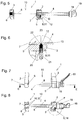
- Fig. 1 shows the essential part of the invention an impeller holder 1 for a bicycle. It may be both the corresponding portion of a front fork wheel fork and the corresponding rear frame portion of a bicycle frame for a rear wheel of the bicycle.
- the wheel itself is in Fig. 1 as also not shown in the other figures. However, it may have a hub known per se, through which the through-axle 4 is pushed, so that the hub and impeller in the intermediate region 10 between the dropouts 2 and 3 of the impeller holder 1 and is rotatably mounted on the stub axle 4.
- Fig. 1 shows the essential part of the invention an impeller holder 1 for a bicycle. It may be both the corresponding portion of a front fork wheel fork and the corresponding rear frame portion of a bicycle frame for a rear wheel of the bicycle.
- the wheel itself is in Fig. 1 as also not shown in the other figures. However, it may have a hub known per se, through which the through-axle 4 is pushed, so
- the thru-axle 4 is shown in the fixed operating state, in which it rotatably supports the hub (not shown) together with the impeller in a defined position about the longitudinal axis 8 of the thru-axle 4 between the dropouts 2 and 3.
- the plug-in axis as known per se, is fixed with its fixation end 7 in the fixing device 6 of the dropout 3.
- the stub axle 4 is inserted through the here in all embodiments circumferentially formed trained through hole 5 in the dropout 2 and stored there.
- the stub axle 4 is attached to the stub axle 4 stop 18 on the outside of the dropout 2. With the handle lever 19, the stub axle 4 can be rotated about its longitudinal axis 8 in order to fix the fixing end 7 in the fixing device 6 of the dropout 3 and to release it again.
- Fig. 2 shows the section AA Fig. 1 in a view from below. Shown is a section through the thru-axle 4 along the longitudinal axis 8 and also through the dropouts 2 and 3.
- the fixing end 7 of the plug-in shaft 4 is formed as an external thread on the through axle 4.
- the fixation device 6 in the dropout 3 is formed in this embodiment as a corresponding internal thread, so that the thru axle 4 can be screwed into the fixation device 6 in this fixation and can be unscrewed for release from this by the thru axle 4 in the respective corresponding direction of rotation about the longitudinal axis rotates.
- Fig. 3 shows area B Fig. 2 increased.
- the locking lug 12 is slidably mounted on the dropout 2 with the through hole 5.
- the detent 12 is located on the outside of the thru axle 4, without locking in this.
- the detent nose 13 corresponding to the detent 12 is in this embodiment, as in Fig. 2 can be seen on the stub axle 4 and here specifically arranged in the region of the fixation end 7 of the thru axle 4.
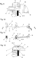
- the Fig. 4 . 5 and 6 now show the dissolved operating state of the thru axle 4 by the thru axle 4 detached from the fixing device 6 in the dropout 3, but is still slidably mounted in fürgansloch 5 along the longitudinal axis 8 of the thru axle 4.
- the thru axle 4 In the 4 to 6 is the thru axle 4 completely pulled out of the intermediate region 10 between the dropouts 2 and 3, so that a not shown here hub of an impeller in the area 10 between the Dropouts 2 and 3 can be introduced and removed from this.
- the inventively designed anti-loss 9 prevents in this dissolved operating state that the thru axle 4 can be completely detached from the impeller holder 1.
- the loss protection 9 holds the stub axle 4 in a position in which the stub axle 4 is still stored in the through hole 5 but completely pulled out of the intermediate region 10 between the dropouts 2 and 3. This position is the example in the 4 to 6 for the first embodiment shown.
- the loss prevention 9 is formed directly in the region of the through hole 5.
- FIGS. 5 and 6 show the longitudinal section along the section line CC Fig. 4 in a view from below.
- Fig. 6 shows the area D Fig. 5 increased.
- the locking lug 12 engages in this position in the dissolved operating state so in the formed on the plug-in axis 4 locking lug receptacle 13 that further withdrawal of the through axle 4 is prevented from the dropout 2.
- this can be seen well on the stop-like end 22 of the latching nose receptacle 13, against which the latching lug 12 bears. The interaction of latching lug 12 and the end 22 of the latching nose receptacle 13 prevents further removal of the through axle 4.
- the fixing device 6 and also according to the fixing end 7 of the thru axle 4 may be formed differently than shown here, as already explained above.
- the Fig. 7 to 12 Now show a second embodiment of how to form the inventive Verlierschutz 9 for the thru axle 4.
- the Fig. 7 to 9 again show the fixed operating state, where Fig. 8 the cut along the cutting plane EE Fig. 7 in a view from below and the Fig. 9 the detail F off Fig. 8 shows.
- the 10 to 12 show according to the dissolved operating state in which the loss prevention 9 prevents the complete removal of the thru axle 4 from the dropout 2.
- the loss protection 9 as a magnetic holding device 14 for magnetically holding the thru axle 4 at the dropout 2 and thus at the dropout with the through hole. 5 educated.
- the magnetic holding device 14 of this embodiment has a, preferably designed as a permanent magnet magnet 15, which is arranged in this embodiment at the dropout 2 with the through hole 5.
- the holding device 14 shown here has a magnetizable material 16 or an additional magnet 17 which is arranged in and / or on the plug-in axis 4, here in the region of the fixing end 7 of the plug-in axis 4.
- Fig. 11 again shows a section along the section line GG Fig. 10 in a bottom view.
- Fig. 12 shows the area H Fig. 11 increased.
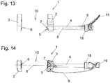
- FIGS. 13 and 14 show a third embodiment. Again, only the differences to the two previously described embodiments are explained. With regard to all other features, reference is made to the description of the first embodiment.
- This is formed in this embodiment as a flexible element in the form of a rope, which on the one hand to the dropout 2 with the through hole 5 and on the other hand Thru-axle 4, here specifically attached to the handle lever 19.
- the length of this flexible element 9 is selected so that the thru axle 4 maximum in the in the FIGS. 13 and 14 shown position can be pulled out. In this position, the intermediate region 10 is in turn completely released from the plug-in axle 4, so that the hub of an impeller can be correspondingly mounted or dismounted.
- Verliersschutz 9 holds the stub axle 4 thus again in a position in which the stub axle 4 still stored in the through hole 5, but completely pulled out of the intermediate region 10 between the dropouts 2 and 3 is.
Landscapes
- Engineering & Computer Science (AREA)
- Mechanical Engineering (AREA)
- Axle Suspensions And Sidecars For Cycles (AREA)
- Lock And Its Accessories (AREA)
Description
- Die vorliegende Erfindung betrifft eine Laufradhalterung, insbesondere für ein Fahrrad, mit zumindest zwei einander gegenüberliegend angeordneten Ausfallenden und zumindest einer Steckachse für ein Laufrad, wobei eines der Ausfallenden ein, insbesondere umfangsgeschlossenes, Durchgangsloch und das dazu gegenüberliegend angeordnete Ausfallende eine Fixierungsvorrichtung für die Steckachse aufweist und die Steckachse in einem fixierten Betriebszustand im Durchgangsloch gelagert und mit einem Fixierungsende der Steckachse in und/oder an der Fixierungsvorrichtung fixiert ist und in einem gelösten Betriebszustand die Steckachse von der Fixierungsvorrichtung losgelöst und im Durchgangsloch entlang einer Längsachse der Steckachse verschiebbar gelagert ist.
- Die Laufräder von Fahrrädern sind mittels Achsen zwischen jeweils zwei Ausfallenden einer Laufradhalterung gelagert und gehalten. Bei der Laufradhalterung kann es sich sowohl um eine Fahrradgabel zum Halten des vorderen Laufrades als auch um einen Hinterbau eines Fahrradrahmens zur Halterung des hinteren Laufrades des Fahrrades handeln. Beim Stand der Technik werden häufig sogenannte Schnellspannachsen eingesetzt, welche eine klemmende Befestigung an den Ausfallenden vorsehen. Um die Schnellspannachsen an den Ausfallenden befestigen zu können, müssen die Ausfallenden nach außen hin jeweils eine Öffnung aufweisen, durch die hindurch die Schnellspannachse eingeführt werden kann. Das Problem der weithin bekannten Technologie mit den Schnellspannachsen besteht darin, dass die Position des Laufrades zwischen den Ausfallenden durch die Schnellspannachse nicht eindeutig vorgegeben ist, was insbesondere bei der Verwendung von Scheibenbremsen, aber auch bei der Verwendung von Felgenbremsen bei nicht exakter Ausrichtung des Laufrades zu Schleifgeräuschen an der Bremse führen kann.
- Dieser Nachteil wurde beim Stand der Technik durch gattungsgemäße Laufradhalterungen mit sogenannten Steckachsen beseitigt. Bei gattungsgemäßen Laufradhalterungen weist eines der Ausfallenden ein, insbesondere umfanggeschlossenes, Durchgangsloch auf, durch das die Steckachse hindurchgesteckt werden kann. Am anderen Ausfallende wird die Steckachse mittels einer Fixierungsvorrichtung fixiert. Dies ermöglicht es, ein Laufrad mittels der Steckachse sehr exakt und in einer definierten Ausrichtung an den Ausfallenden zu befestigen. Zusätzlich weisen Steckachsen in der Regel auch eine höhere Stabilität und Steifigkeit als die oben genannten Schnellspannachsen auf.
- Gattungsgemäße Laufradhalterungen sind in der
WO 2005/120940 A2 und derUS 2016/0016628 gezeigt. - Aufgabe der Erfindung ist es bei gattungsgemäßen Laufradhalterungen mit Steckachsen die Handhabung und den Montageprozess weiter zu erleichtern.
- Hierfür ist eine Laufradhalterung gemäß Patentanspruch 1 vorgesehen.
- Durch den erfindungsgemäß vorgesehenen Verlierschutz ist sichergestellt, dass die Steckachse auch im gelösten Betriebszustand nicht vollständig von den restlichen Bauteilen und insbesondere vollständig von beiden Ausfallenden der Laufradhalterung entfernt werden kann. Es wird vermieden, dass bei der Montage die Steckachse im gelösten Betriebszustand herunterfallen oder verloren gehen kann. Weiters muss die Steckachse auch nicht nach vollständigem Lösen von der restlichen Laufradhalterung, von Hand gehalten werden, da sie nach wie vor mittels des Verlierschutzes weiterhin an den restlichen Bauteilen der Laufradhalterung gehalten ist. Der erfindungsgemäß vorgesehene Verlierschutz verhindert somit, dass die Steckachse im gelösten Betriebszustand vollständig von den sonstigen Bauteilen der Laufradhalterung gelöst wird. Dies hat den Vorteil, dass man zur Montage des Laufrades an der Laufradhalterung die Steckachse nicht permanent festhalten muss. Außerdem befindet sich die Steckachse beim Montage- und Demontagevorgang an einer definierten, durch den Verlierschutz vorgegebenen Position. Beides vereinfacht sowohl die Montage als auch die Demontage eines Laufrades in der Laufradhalterung.
- Bei erfindungsgemäßen Laufradhalterungen kann es sich sowohl um solche zur Aufnahme eines vorderen Laufrades als auch eines hinteren Laufrades des Fahrrades handeln. Erfindungsgemäße Laufradhalterungen können also als sogenannte Fahrrad- bzw. Federgabel ausgebildet sein. Es kann sich bei erfindungsgemäßen Laufradhalterungen aber auch um den Teil des Hinterbaus eines Fahrradrahmens handeln, in den das hintere Laufrad eingesetzt wird. Darüber hinaus müssen erfindungsgemäße Laufradhalterungen nicht zwingend nur bei Fahrrädern realisiert werden. Erfindungsgemäße Laufradhalterungen könnten auch an anderen Fahrzeugen, insbesondere mit zwei oder mehr Laufrädern, realisiert werden. Die Ausfallenden sind grundsätzlich die Teile bzw. Bereiche der Laufradhalterung, an denen die Steckachse befestigt wird. In der Regel ist eine Steckachse im fixierten Betriebszustand an zwei einander gegenüberliegend angeordneten Ausfallenden befestigt. Eines der Ausfallenden weist das Durchgangsloch zum Hindurchschieben der Steckachse auf. Das andere bzw. dazu gegenüberliegend angeordnete Ausfallende weist die Fixierungsvorrichtung zur Fixierung der Steckachse auf.
- Das Durchgangsloch für die Steckachse in dem einen der Ausfallenden ist günstigerweise umfangsgeschlossen ausgebildet. Es ist also von einer Ringstruktur des Ausfallendes mit in sich geschlossenem Ring umgeben. Bei der Fixierungsvorrichtung am anderen Ausfallende kann es sich z.B., wie an sich bekannt, um ein Innengewinde im Ausfallende handeln. In diesem Fall weist die Steckachse als Fixierungsende ein entsprechendes Außengewinde auf, mit dem die Steckachse in das Innengewinde der Fixierungsvorrichtung eingeschraubt werden kann. Grundsätzlich sind natürlich aber auch andere Fixierungsvorrichtungen zur Befestigung der Steckachse an dem einen der Ausfallenden denkbar. Hierfür könnten grundsätzlich auch andere Schraubverbindungen, entsprechend feste Steckverbindungen, Klemmeinrichtungen, bajonettverschlussartige Fixierungsvorrichtungen oder dergleichen eingesetzt werden. Das Fixierungsende der Steckachse wird dann jeweils entsprechend korrespondierend ausgebildet.
- Der Verlierschutz für die Steckachse kann grundsätzlich sehr unterschiedlich ausgebildet sein.
- Eine erste Variante sieht ein flexibles Element vor, mit dem die Steckachse an einem der Ausfallenden oder an sonstigen Bauteilen der Laufradhalterung befestigt ist. Das flexible Element kann z.B. ein Band, ein Seil, ein Draht oder dergleichen sein.
- Besonders bevorzugte Ausgestaltungsformen der Erfindung sehen vor, dass der Verlierschutz an und/oder in dem Ausfallende mit dem Durchgangsloch, vorzugsweise im Bereich des Durchgangslochs, angeordnet, vorzugsweise ausgebildet oder befestigt, ist.
- Gemäß der Erfindung ist vorgesehen, dass der Verlierschutz die Steckachse in einer Stellung festhält, in der die Steckachse in dem Durchgangsloch gelagert und vollständig aus einem Zwischenbereich zwischen den Ausfallenden herausgezogen ist. Hierdurch kann die Steckachse vollständig aus dem Zwischenbereich zwischen den Ausfallenden herausgezogen werden, um dann dennoch in dem Durchgangsloch gelagert und dort vom Verlierschutz der Steckachse festgehalten zu sein. Hierdurch wird verhindert, dass die Steckachse vollkommen aus dem Durchgangsloch des Ausfallendes herausfällt und damit vollständig von den sonstigen Bauteilen der Laufradhalterung getrennt wird. Durch solche Arten von Ausgestaltungsformen des Verlierschutz wird also verhindert, dass die Steckachse vollständig aus dem Durchgangsloch des einen Ausfallendes herausgezogen wird. Die Steckachse verbleibt somit auch in der gelösten Betriebsstellung mittels des Verlierschutzes sicher in dem zumindest einen der Ausfallenden, was die Handhabung und den Montage- wie auch den Demontageprozess erleichtert und auch beschleunigt.
- Es kann z.B. vorgesehen sein, dass der Verlierschutz eine Rastvorrichtung zur Ausbildung einer Rastverbindung zwischen der Steckachse und einem der Ausfallenden, vorzugsweise dem Ausfallende mit dem Durchgangsloch, aufweist oder ist. Die Rastvorrichtung kann z.B. eine federbelastete oder selbstfedernde Rastnase und eine Rastnasenaufnahme zur Aufnahme der Rastnase aufweisen. Es kann dann z.B. vorgesehen sein, dass die Rastnase an und/oder in dem Ausfallende mit dem Durchgangsloch, vorzugsweise verschiebbar, gelagert ist. Die Rastnasenaufnahme kann z.B. in und/oder an der Steckachse, vorzugsweise im Bereich des Fixierungsendes der Steckachse angeordnet sein. Natürlich könnte auch andersherum eine entsprechende Rastnase an der Steckachse, insbesondere an deren Fixierungsende, ausgebildet sein. Dann würde das Ausfallende die Rastnasenaufnahme aufweisen bzw. tragen.
- Andere Varianten der Erfindung können vorsehen, dass der Verlierschutz eine magnetische Haltevorrichtung zum magnetischen Festhalten der Steckachse an einem der Ausfallenden, vorzugsweise an dem Ausfallende mit dem Durchgangsloch, aufweist.
- Die magnetische Haltevorrichtung sollte dann zumindest einen Magneten, vorzugsweise in Form eines Permanentmagneten, aufweisen. Mit diesem Magnet kann dann magnetisierbares Material zusammenwirken oder es kann ein Zusatzmagnet, vorzugsweise ebenfalls in Form eines Permanentmagneten, vorgesehen sein, mit dem der Magnet zur Ausbildung der magnetischen Haltevorrichtung zusammenwirkt. In solchen Ausgestaltungsformen könnte man den Magnet auch als Hauptmagnet bezeichnen, um ihn sprachlich klar vom Zusatzmagneten zu unterscheiden. Bevorzugte Varianten sehen vor, dass der Magnet bzw. Hauptmagnet an und/oder in dem Ausfallende mit dem Durchgangsloch gelagert bzw. dort angeordnet ist. Die Steckachse kann dann entsprechend magnetisierbares Material oder den Zusatzmagneten aufweisen. Vorzugsweise befindet sich das magnetisierbare Material bzw. der Zusatzmagnet im Bereich des Fixierungsendes der Steckachse. Natürlich ist auch hier eine Anordnung andersherum denkbar.
- In der nachfolgenden Figurenbeschreibung werden bevorzugte Ausgestaltungsformen der Erfindung beispielhaft erläutert. Es zeigen:
-
Fig. 1 bis 6 Darstellungen zu einem ersten erfindungsgemäßen Ausführungsbeispiel; -
Fig. 7 bis 12 Darstellungen zu einem zweiten erfindungsgemäßen Ausführungsbeispiel und -
Fig. 13 und 14 Darstellungen zu einem dritten erfindungsgemäßen Ausführungsbeispiel. -
Fig. 1 zeigt den erfindungswesentlichen Bereich einer Laufradhalterung 1 für ein Fahrrad. Es kann sich sowohl um den entsprechenden Bereich einer Fahrrad- bzw. Federgabel für ein vorderes Laufrad als auch um den entsprechenden Bereich eines Hinterbaus eines Fahrradrahmens für ein hinteres Laufrad des Fahrrades handeln. Das Laufrad selbst ist inFig. 1 wie auch in den anderen Figuren nicht dargestellt. Es kann aber eine an sich bekannte Nabe aufweisen, durch die die Steckachse 4 hindurchgeschoben wird, sodass sich die Nabe samt Laufrad im Zwischenbereich 10 zwischen den Ausfallenden 2 und 3 der Laufradhalterung 1 befindet und auf der Steckachse 4 drehbar gelagert ist. InFig. 1 ist die Steckachse 4 im fixierten Betriebszustand dargestellt, in dem sie die hier nicht dargestellte Nabe samt Laufrad in definierter Position um die Längsachse 8 der Steckachse 4 drehbar zwischen den Ausfallenden 2 und 3 lagert. In diesem fixierten Betriebszustand ist die Steckachse, wie an sich bekannt, mit ihrem Fixierungsende 7 in der Fixierungsvorrichtung 6 des Ausfallendes 3 fixiert. Weiters ist die Steckachse 4 durch das hier in allen Ausführungsbeispielen umfangsgeschlossen ausgebildete Durchgangsloch 5 im Ausfallende 2 hindurchgesteckt und dort gelagert. In diesem fixierten Betriebszustand gemäßFig. 1 liegt der an der Steckachse 4 befestigte Anschlag 18 auf der Außenseite des Ausfallendes 2 an. Mit dem Griffhebel 19 kann die Steckachse 4 um ihre Längsachse 8 gedreht werden, um das Fixierungsende 7 in der Fixierungsvorrichtung 6 des Ausfallendes 3 zu fixieren und von diesem wieder zu lösen. -
Fig. 2 zeigt den Schnitt AA ausFig. 1 in einer Ansicht von unten. Dargestellt ist ein Schnitt durch die Steckachse 4 entlang der Längsachse 8 und auch durch die Ausfallenden 2 und 3. InFig. 2 ist gut zu sehen, dass in diesem, wie auch in den anderen hier gezeigten Ausführungsbeispielen das Fixierungsende 7 der Steckachse 4 als Außengewinde auf der Steckachse 4 ausgebildet ist. Die Fixierungsvorrichtung 6 im Ausfallende 3 ist in diesem Ausführungsbeispiel als ein korrespondierendes Innengewinde ausgebildet, sodass die Steckachse 4 zur Fixierung in der Fixierungsvorrichtung 6 in diese eingeschraubt und zum Lösen aus dieser ausgeschraubt werden kann, indem man die Steckachse 4 in der jeweils entsprechenden Drehrichtung um die Längsachse 8 dreht.Fig. 3 zeigt den Bereich B ausFig. 2 vergrößert. Dargestellt ist inFig. 3 und in dem entsprechenden Bereich vonFig. 2 ein Teil des in dem ersten Ausführungsbeispiel als Rastvorrichtung 11 ausgebildeten Verlierschutzes 9, welcher verhindert, dass die Steckachse 4 im gelösten Betriebszustand vollständig von den anderen Bauteilen der Laufradhalterung 1 und damit von den Ausfallenden 2 und 3 gelöst werden kann. InFig. 3 ist gut zu sehen, dass die hier den Verlierschutz 9 bildende Rastvorrichtung 11 eine federbelastete oder gegebenenfalls auch selbstfedernde Rastnase 12 aufweist. Im gezeigten Ausführungsbeispiel handelt es sich um eine mittels der Spannfeder 20 vorgespannte und in einer Schraube 21 gelagerte Rastnase 12. Durch entsprechend weites Ein- oder Ausschrauben der Schraube 21 in und aus dem Ausfallende 2 kann die Vorspannung der Spannfeder 20 eingestellt werden. In diesem Ausführungsbeispiel ist also die Rastnase 12 an dem Ausfallende 2 mit dem Durchgangsloch 5 verschiebbar gelagert. Im in denFig. 1 bis 3 dargestellten fixierten Betriebszustand liegt die Rastnase 12 außen an der Steckachse 4 an, ohne in diese einzurasten. Die zu der Rastnase 12 korrespondierenden Rastnasenaufnahme 13 ist in diesem Ausführungsbeispiel, wie dies inFig. 2 zu sehen ist, an der Steckachse 4 und hier konkret im Bereich des Fixierungsendes 7 der Steckachse 4 angeordnet. Günstigerweise ist die Rastnasenaufnahme 13, wie hier auch realisiert, als in sich umfangsgeschlossene, nach außen offene Nut bzw. Kerbe in der Steckachse 4 realisiert. - Die
Fig. 4 ,5 und 6 zeigen nun den gelösten Betriebszustand der Steckachse 4, indem die Steckachse 4 von der Fixierungsvorrichtung 6 im Ausfallende 3 losgelöst, aber noch im Durchgansloch 5 entlang der Längsachse 8 der Steckachse 4 verschiebbar gelagert ist. In denFig. 4 bis 6 ist die Steckachse 4 vollständig aus dem Zwischenbereich 10 zwischen den Ausfallenden 2 und 3 herausgezogen, sodass eine hier nicht dargestellte Nabe eines Laufrades in den Bereich 10 zwischen den Ausfallenden 2 und 3 eingeführt und aus diesem herausgenommen werden kann. Der erfindungsgemäß ausgebildete Verlierschutz 9 verhindert in diesem gelösten Betriebszustand, dass die Steckachse 4 vollständig von der Laufradhalterung 1 gelöst werden kann. In allen drei hier dargestellten Ausführungsbeispielen hält der Verlierschutz 9 die Steckachse 4 in einer Stellung fest, in der die Steckachse 4 in dem Durchgangsloch 5 noch gelagert aber vollständig aus dem Zwischenbereich 10 zwischen den Ausfallenden 2 und 3 herausgezogen ist. Diese Stellung ist die z.B. in denFig. 4 bis 6 für das erste Ausführungsbeispiel gezeigt. - Weiters ist festzuhalten, dass in allen hier dargestellten Ausführungsbeispielen der Verlierschutz an und/oder in dem Ausfallende 2 mit dem Durchgangsloch 5 angeordnet, vorzugsweise ausgebildet oder zumindest befestigt ist. In den ersten beiden Ausführungsbeispielen ist der Verlierschutz 9 direkt im Bereich des Durchgangslochs 5 ausgebildet.
- Die Wirkungsweise des hier im ersten Ausführungsbeispiels als Rastvorrichtung 11 ausgebildeten Verlierschutzes 9 ist besonders gut in den
Fig. 5 und 6 zu sehen.Fig. 5 zeigt dabei den Längsschnitt entlang der Schnittlinie CC ausFig. 4 in einer Ansicht von unten.Fig. 6 zeigt den Bereich D ausFig. 5 vergrößert. Insbesondere inFig. 6 ist gut zu erkennen, dass die Rastnase 12 in dieser Stellung im gelösten Betriebszustand so in die an der Steckachse 4 ausgebildete Rastnasenaufnahme 13 eingreift, dass ein weiteres Herausziehen der Steckachse 4 aus dem Ausfallende 2 verhindert ist. InFig. 6 ist dies gut an dem anschlagartig ausgebildeten Ende 22 der Rastnasenaufnahme 13 zu erkennen, an dem die Rastnase 12 anliegt. Das Zusammenwirken von Rastnase 12 und Ende 22 der Rastnasenaufnahme 13 verhindert ein weiteres Herausziehen der Steckachse 4. - Wird die Steckachse 4 hingegen wieder in Richtung zum anderen Ausfallende 3 hin eingeschoben, so wird die Rastnase 12 von der Schrägfläche 23 der Rastnasenaufnahme 13 aus der Rastnasenaufnahme 13 herausgedrückt, sodass die Steckachse 4 dann wieder in Richtung hin zum Ausfallende 3 verschoben und mit ihrem Fixierungsende 7 in der Fixierungsvorrichtung 6 fixiert werden kann, womit dann wieder der fixierte Betriebszustand gemäß der
Fig. 1 bis 3 erreicht ist. - Der Vollständigkeit halber wird darauf hingewiesen, dass in allen Ausführungsbeispielen die Fixiervorrichtung 6 und auch entsprechend das Fixierungsende 7 der Steckachse 4 anders als hier dargestellt ausgebildet sein können, wie dies eingangs bereits erläutert wurde.
- Die
Fig. 7 bis 12 zeigen nun ein zweites Ausführungsbeispiel, wie man den erfindungsgemäßen Verlierschutz 9 für die Steckachse 4 ausbilden kann. DieFig. 7 bis 9 zeigen wiederum den fixierten Betriebszustand, wobeiFig. 8 den Schnitt entlang der Schnittebene EE ausFig. 7 in einer Ansicht von unten und dieFig. 9 das Detail F ausFig. 8 zeigt. DieFig. 10 bis 12 zeigen entsprechend den gelösten Betriebszustand, in dem der Verlierschutz 9 das vollständige Entfernen der Steckachse 4 aus dem Ausfallende 2 verhindert. - Im Folgenden wird beim zweiten Ausführungsbeispiel nur noch auf die Unterschiede zum ersten Ausführungsbeispiel eingegangen. Bezüglich aller anderen Merkmale wird auf die obigen Schilderungen verwiesen.
- Der Unterschied zwischen dem ersten und dem zweiten Ausführungsbeispiel liegt in der Art der Ausgestaltung des Verlierschutzes 9. Im zweiten Ausführungsbeispiel ist der Verlierschutz 9 als eine magnetische Haltevorrichtung 14 zum magnetischen Festhalten der Steckachse 4 an dem Ausfallende 2 und damit an dem Ausfallende mit dem Durchgangsloch 5 ausgebildet. Die magnetische Haltevorrichtung 14 dieses Ausführungsbeispiels weist einen, vorzugsweise als Permanentmagnet ausgebildeten Magneten 15 auf, welcher in diesem Ausführungsbeispiel am Ausfallende 2 mit dem Durchgangsloch 5 angeordnet ist. Weiters weist die hier dargestellte Haltevorrichtung 14 ein magnetisierbares Material 16 oder einen Zusatzmagneten 17 auf, welches bzw. welcher in und/oder an der Steckachse 4, hier im Bereich des Fixierungsendes 7 der Steckachse 4, angeordnet ist. In dem gelösten Betriebszustand, wie er in den
Fig. 10 bis 12 dargestellt ist, ist die Steckachse 4 wiederum vollständig aus dem Zwischenbereich 10 zwischen den Ausfallenden 2 und 3 herausgezogen. Durch das Zusammenwirken des Magneten 15 mit dem magnetisierbaren Material 16 oder dem Zusatzmagnet 17 wird die Steckachse 4 in dieser Stellung, wie besonders gut inFig. 12 zu sehen, so festgehalten, dass der erfindungsgemäße Verlierschutz 9 ausgebildet ist, welcher verhindert, dass die Steckachse 4 auch noch aus dem Ausfallende 2 vollständig entfernt wird.Fig. 11 zeigt wiederum einen Schnitt entlang der Schnittlinie GG ausFig. 10 in einer Unteransicht.Fig. 12 zeigt den Bereich H ausFig. 11 vergrößert. - Die
Fig. 13 und 14 zeigen ein drittes Ausführungsbeispiel. Auch hier werden nur noch die Unterschiede zu den beiden bisher geschilderten Ausführungsbeispielen erläutert. Bezüglich aller anderen Merkmale wird auf die Schilderung des ersten Ausführungsbeispiels verwiesen. - Auch in diesem dritten Ausführungsbeispiel besteht der wesentliche Unterschied zum ersten Ausführungsbeispiel lediglich in der Ausbildung des erfindungsgemäßen Velierschutzes 9. Dieser ist in diesem Ausführungsbeispiel als ein flexibles Element in Form eines Seiles ausgebildet, welches einerseits an dem Ausfallende 2 mit dem Durchgangsloch 5 und andererseits an der Steckachse 4, hier konkret an deren Griffhebel 19 befestigt ist. In diesem Ausführungsbeispiel ist die Länge dieses flexiblen Elementes 9 so gewählt, dass die Steckachse 4 maximal in die in den
Fig. 13 und 14 dargestellte Stellung herausgezogen werden kann. In dieser Stellung ist der Zwischenbereich 10 von der Steckachse 4 wiederum vollständig freigegeben, sodass die Nabe eines Laufrades entsprechend montiert oder demontiert werden kann. Bei dieser Ausgestaltungsform und Länge des flexiblen Elementes 9 hält der so ausgebildete Verlierschutz 9 die Steckachse 4 somit wiederum in einer Stellung fest, in der die Steckachse 4 in dem Durchgangsloch 5 noch gelagert, aber vollständig aus dem Zwischenbereich 10 zwischen den Ausfallenden 2 und 3 herausgezogen ist. -
- 1
- Laufradhalterung
- 2
- Ausfallende
- 3
- Ausfallende
- 4
- Steckachse
- 5
- Durchgangsloch
- 6
- Fixierungsvorrichtung
- 7
- Fixierungsende
- 8
- Längsachse
- 9
- Verlierschutz
- 10
- Zwischenbereich
- 11
- Rastvorrichtung
- 12
- Rastnase
- 13
- Rastnasenaufnahme
- 14
- magnetische Haltevorrichtung
- 15
- Magnet
- 16
- magnetisierbares Material
- 17
- Zusatzmagnet
- 18
- Anschlag
- 19
- Griffhebel
- 20
- Spannfeder
- 21
- Schraube
- 22
- Ende
- 23
- Schrägfläche
Claims (8)
- Laufradhalterung (1), insbesondere für ein Fahrrad, mit zumindest zwei einander gegenüberliegend angeordneten Ausfallenden (2, 3) und zumindest einer Steckachse (4) für ein Laufrad, wobei eines der Ausfallenden (2) ein, insbesondere umfangsgeschlossenes, Durchgangsloch (5) und das dazu gegenüberliegend angeordnete Ausfallende (3) eine Fixierungsvorrichtung (6) für die Steckachse (4) aufweist und die Steckachse (4) in einem fixierten Betriebszustand im Durchgangsloch (5) gelagert und mit einem Fixierungsende (7) der Steckachse (4) in und/oder an der Fixierungsvorrichtung (6) fixiert ist und in einem gelösten Betriebszustand die Steckachse (4) von der Fixierungsvorrichtung (6) losgelöst und im Durchgangsloch (5) entlang einer Längsachse (8) der Steckachse (4) verschiebbar gelagert ist, dadurch gekennzeichnet, dass die Laufradhalterung (1) einen Verlierschutz (9) für die Steckachse (4) im gelösten Betriebszustand aufweist und der Verlierschutz (9) die Steckachse (4) in einer Stellung festhält, in der die Steckachse (4) in dem Durchgangsloch (5) gelagert und vollständig aus einem Zwischenbereich (10) zwischen den Ausfallenden (2, 3) herausgezogen ist.
- Laufradhalterung (1) nach Anspruch 1, dadurch gekennzeichnet, dass der Verlierschutz (9) an und/oder in dem Ausfallende (2) mit dem Durchgangsloch (5), vorzugsweise im Bereich des Durchgangslochs (5), angeordnet, vorzugsweise ausgebildet oder befestigt, ist.
- Laufradhalterung (1) nach einem der Ansprüche 1 bis 2, dadurch gekennzeichnet, dass der Verlierschutz (9) eine Rastvorrichtung (11) zur Ausbildung einer Rastverbindung zwischen der Steckachse (4) und einem der Ausfallenden (2, 3), vorzugsweise dem Ausfallende (2) mit dem Durchgangsloch (5), aufweist.
- Laufradhalterung (1) nach Anspruch 3, dadurch gekennzeichnet, dass die Rastvorrichtung (11) eine festbelastete oder federnde Rastnase (12) und eine Rastnasenaufnahme (13) zur Aufnahme der Rastnase (12) aufweist.
- Laufradhalterung (1) nach Anspruch 4, dadurch gekennzeichnet, dass die Rastnase (12) an und/oder in dem Ausfallende (2) mit dem Durchgangsloch (5), vorzugsweise verschiebbar, gelagert ist und/oder dass die Rastnasenaufnahme (13) in und/oder an der Steckachse (4), vorzugsweise im Bereich des Fixierungsendes (7) der Steckachse (4), angeordnet ist.
- Laufradhalterung (1) nach einem der Ansprüche 1 bis 2, dadurch gekennzeichnet, dass der Verlierschutz (9) eine magnetische Haltevorrichtung (14) zum magnetischen Festhalten der Steckachse (4) an einem der Ausfallenden (2, 3), vorzugsweise an dem Ausfallende (2) mit dem Durchgangsloch (5), aufweist.
- Laufradhalterung (1) nach Anspruch 6, dadurch gekennzeichnet, dass die magnetische Haltevorrichtung (14) einen Magneten (15), vorzugsweise Permanentmagneten, und ein damit zusammenwirkendes magnetisierbares Material (16) oder einen damit zusammenwirkenden Zusatzmagneten (17), vorzugsweise Zusatzpermanentmagneten, aufweist.
- Laufradhalterung (1) nach Anspruch 6, dadurch gekennzeichnet, dass der Magnet (15) an und/oder in dem Ausfallende (2) mit dem Durchgangsloch (5) angeordnet ist und/oder das magnetisierbare Material (16) oder der Zusatzmagnet (17) in und/oder an der Steckachse (4), vorzugsweise im Bereich des Fixierungsendes (7) der Steckachse (4), angeordnet ist.
Applications Claiming Priority (1)
| Application Number | Priority Date | Filing Date | Title |
|---|---|---|---|
| ATA262/2017A AT520163A1 (de) | 2017-06-21 | 2017-06-21 | Laufradhalterung |
Publications (2)
| Publication Number | Publication Date |
|---|---|
| EP3418172A1 EP3418172A1 (de) | 2018-12-26 |
| EP3418172B1 true EP3418172B1 (de) | 2019-09-11 |
Family
ID=62567405
Family Applications (1)
| Application Number | Title | Priority Date | Filing Date |
|---|---|---|---|
| EP18176181.8A Active EP3418172B1 (de) | 2017-06-21 | 2018-06-06 | Laufradhalterung |
Country Status (2)
| Country | Link |
|---|---|
| EP (1) | EP3418172B1 (de) |
| AT (1) | AT520163A1 (de) |
Family Cites Families (6)
| Publication number | Priority date | Publication date | Assignee | Title |
|---|---|---|---|---|
| JPH0522285U (ja) * | 1991-09-02 | 1993-03-23 | カヤバ工業株式会社 | フロントフオークの車軸取付構造 |
| EP0993402B1 (de) * | 1997-07-11 | 2002-10-02 | Inc. Shimano | Nabenmontagevorrichtung für zweirad |
| GB2414971B (en) * | 2004-06-09 | 2006-12-27 | Simon Charles Bartlett | Improvements to wheel clamping assemblies |
| US7628416B2 (en) * | 2007-02-21 | 2009-12-08 | Shimano Inc. | Bicycle wheel securing structure |
| US9604689B2 (en) * | 2014-07-16 | 2017-03-28 | Ford Global Technologies, Llc | Bicycle frame joint locking mechanism |
| DE202015005524U1 (de) * | 2015-08-05 | 2015-10-02 | tune U. Fahl e.K. | Schnellverschluss für Fahrräder mit Justierfunktion |
-
2017
- 2017-06-21 AT ATA262/2017A patent/AT520163A1/de not_active Application Discontinuation
-
2018
- 2018-06-06 EP EP18176181.8A patent/EP3418172B1/de active Active
Non-Patent Citations (1)
| Title |
|---|
| None * |
Also Published As
| Publication number | Publication date |
|---|---|
| EP3418172A1 (de) | 2018-12-26 |
| AT520163A1 (de) | 2019-01-15 |
Similar Documents
| Publication | Publication Date | Title |
|---|---|---|
| EP2158120B1 (de) | Schaltauge mit einsetzhilfe | |
| DE20006591U1 (de) | Ratschenradpositioniereinrichtung für einen Ratschensteckschlüssel mit umkehrbarer Arbeitsrichtung | |
| DE102015121218B3 (de) | Schnellspann-Steckachse für Zweiräder | |
| DE202013009812U1 (de) | Steckbare Achseneinrichtung für ein Laufrad, insbesondere für ein Laufrad eines Fahrrades | |
| DE102010024473A1 (de) | Achssystem für ein Zweirad | |
| DE3224589A1 (de) | Gepaecktraeger fuer ein zweirad | |
| DE102011001875B4 (de) | Schutzblech | |
| DE102013203213B4 (de) | Fahrrad-Bremsbaueinheit | |
| EP3418172B1 (de) | Laufradhalterung | |
| DE2429665B2 (de) | Blockiervorrichtung für ein Motorfahrzeug | |
| DE202016106746U1 (de) | Schnellspanner für Fahrräder | |
| DE102004009927A1 (de) | Haltevorrichtung für eine Sattelstütze | |
| DE202014103414U1 (de) | Steckachsenbefestigungssystem für Hinterachsen von Fahrrädern und Schaltauge hierfür | |
| DE3643333C2 (de) | Anordnung zur Anbringung eines Bremsklotzes bei einer Scheibenbremse | |
| DE19614494C1 (de) | Diebstahlsicherung für Fahrräder durch Verhinderung des Antriebs | |
| DE202008016511U1 (de) | Schnell lösbare Befestigungseinrichtung für Fahrräder | |
| DE102011056319A1 (de) | Luftleitvorrichtung | |
| DE202016102676U1 (de) | Verbesserte Schnellspann-Steckachse für Zweiräder | |
| DE102011114835A1 (de) | Schutzvorrichtung für ein Fahrradkettenschaltwerk | |
| EP2894089A1 (de) | Set mit Elektromotor für Fahrräder | |
| EP4232343B1 (de) | Griffkappe | |
| DE112006000040B4 (de) | Vorrichtung zur Sicherung eines Rades in einer Gabel | |
| DE202016003786U1 (de) | Fahrradständer | |
| DE9213309U1 (de) | Schlagkopfanordnung für einen Schlagwalzenbrecher | |
| DE625883C (de) | Radtraeger zum Befestigen eines oder mehrerer Ersatzraeder an einem Kraftwagen |
Legal Events
| Date | Code | Title | Description |
|---|---|---|---|
| PUAI | Public reference made under article 153(3) epc to a published international application that has entered the european phase |
Free format text: ORIGINAL CODE: 0009012 |
|
| STAA | Information on the status of an ep patent application or granted ep patent |
Free format text: STATUS: THE APPLICATION HAS BEEN PUBLISHED |
|
| AK | Designated contracting states |
Kind code of ref document: A1 Designated state(s): AL AT BE BG CH CY CZ DE DK EE ES FI FR GB GR HR HU IE IS IT LI LT LU LV MC MK MT NL NO PL PT RO RS SE SI SK SM TR |
|
| AX | Request for extension of the european patent |
Extension state: BA ME |
|
| STAA | Information on the status of an ep patent application or granted ep patent |
Free format text: STATUS: REQUEST FOR EXAMINATION WAS MADE |
|
| 17P | Request for examination filed |
Effective date: 20190405 |
|
| RBV | Designated contracting states (corrected) |
Designated state(s): AL AT BE BG CH CY CZ DE DK EE ES FI FR GB GR HR HU IE IS IT LI LT LU LV MC MK MT NL NO PL PT RO RS SE SI SK SM TR |
|
| GRAP | Despatch of communication of intention to grant a patent |
Free format text: ORIGINAL CODE: EPIDOSNIGR1 |
|
| STAA | Information on the status of an ep patent application or granted ep patent |
Free format text: STATUS: GRANT OF PATENT IS INTENDED |
|
| INTG | Intention to grant announced |
Effective date: 20190604 |
|
| GRAS | Grant fee paid |
Free format text: ORIGINAL CODE: EPIDOSNIGR3 |
|
| GRAJ | Information related to disapproval of communication of intention to grant by the applicant or resumption of examination proceedings by the epo deleted |
Free format text: ORIGINAL CODE: EPIDOSDIGR1 |
|
| GRAL | Information related to payment of fee for publishing/printing deleted |
Free format text: ORIGINAL CODE: EPIDOSDIGR3 |
|
| STAA | Information on the status of an ep patent application or granted ep patent |
Free format text: STATUS: REQUEST FOR EXAMINATION WAS MADE |
|
| GRAR | Information related to intention to grant a patent recorded |
Free format text: ORIGINAL CODE: EPIDOSNIGR71 |
|
| STAA | Information on the status of an ep patent application or granted ep patent |
Free format text: STATUS: GRANT OF PATENT IS INTENDED |
|
| GRAA | (expected) grant |
Free format text: ORIGINAL CODE: 0009210 |
|
| STAA | Information on the status of an ep patent application or granted ep patent |
Free format text: STATUS: THE PATENT HAS BEEN GRANTED |
|
| INTC | Intention to grant announced (deleted) | ||
| RIN1 | Information on inventor provided before grant (corrected) |
Inventor name: SCHMEISER, JONAS |
|
| INTG | Intention to grant announced |
Effective date: 20190726 |
|
| AK | Designated contracting states |
Kind code of ref document: B1 Designated state(s): AL AT BE BG CH CY CZ DE DK EE ES FI FR GB GR HR HU IE IS IT LI LT LU LV MC MK MT NL NO PL PT RO RS SE SI SK SM TR |
|
| REG | Reference to a national code |
Ref country code: GB Ref legal event code: FG4D Free format text: NOT ENGLISH |
|
| REG | Reference to a national code |
Ref country code: CH Ref legal event code: EP |
|
| REG | Reference to a national code |
Ref country code: AT Ref legal event code: REF Ref document number: 1178105 Country of ref document: AT Kind code of ref document: T Effective date: 20190915 |
|
| REG | Reference to a national code |
Ref country code: CH Ref legal event code: NV Representative=s name: LUCHS AND PARTNER AG PATENTANWAELTE, CH |
|
| REG | Reference to a national code |
Ref country code: DE Ref legal event code: R096 Ref document number: 502018000205 Country of ref document: DE Ref country code: IE Ref legal event code: FG4D Free format text: LANGUAGE OF EP DOCUMENT: GERMAN |
|
| REG | Reference to a national code |
Ref country code: NL Ref legal event code: MP Effective date: 20190911 |
|
| REG | Reference to a national code |
Ref country code: LT Ref legal event code: MG4D |
|
| PG25 | Lapsed in a contracting state [announced via postgrant information from national office to epo] |
Ref country code: SE Free format text: LAPSE BECAUSE OF FAILURE TO SUBMIT A TRANSLATION OF THE DESCRIPTION OR TO PAY THE FEE WITHIN THE PRESCRIBED TIME-LIMIT Effective date: 20190911 Ref country code: HR Free format text: LAPSE BECAUSE OF FAILURE TO SUBMIT A TRANSLATION OF THE DESCRIPTION OR TO PAY THE FEE WITHIN THE PRESCRIBED TIME-LIMIT Effective date: 20190911 Ref country code: LT Free format text: LAPSE BECAUSE OF FAILURE TO SUBMIT A TRANSLATION OF THE DESCRIPTION OR TO PAY THE FEE WITHIN THE PRESCRIBED TIME-LIMIT Effective date: 20190911 Ref country code: FI Free format text: LAPSE BECAUSE OF FAILURE TO SUBMIT A TRANSLATION OF THE DESCRIPTION OR TO PAY THE FEE WITHIN THE PRESCRIBED TIME-LIMIT Effective date: 20190911 Ref country code: BG Free format text: LAPSE BECAUSE OF FAILURE TO SUBMIT A TRANSLATION OF THE DESCRIPTION OR TO PAY THE FEE WITHIN THE PRESCRIBED TIME-LIMIT Effective date: 20191211 Ref country code: NO Free format text: LAPSE BECAUSE OF FAILURE TO SUBMIT A TRANSLATION OF THE DESCRIPTION OR TO PAY THE FEE WITHIN THE PRESCRIBED TIME-LIMIT Effective date: 20191211 |
|
| PG25 | Lapsed in a contracting state [announced via postgrant information from national office to epo] |
Ref country code: AL Free format text: LAPSE BECAUSE OF FAILURE TO SUBMIT A TRANSLATION OF THE DESCRIPTION OR TO PAY THE FEE WITHIN THE PRESCRIBED TIME-LIMIT Effective date: 20190911 Ref country code: LV Free format text: LAPSE BECAUSE OF FAILURE TO SUBMIT A TRANSLATION OF THE DESCRIPTION OR TO PAY THE FEE WITHIN THE PRESCRIBED TIME-LIMIT Effective date: 20190911 Ref country code: ES Free format text: LAPSE BECAUSE OF FAILURE TO SUBMIT A TRANSLATION OF THE DESCRIPTION OR TO PAY THE FEE WITHIN THE PRESCRIBED TIME-LIMIT Effective date: 20190911 Ref country code: GR Free format text: LAPSE BECAUSE OF FAILURE TO SUBMIT A TRANSLATION OF THE DESCRIPTION OR TO PAY THE FEE WITHIN THE PRESCRIBED TIME-LIMIT Effective date: 20191212 Ref country code: RS Free format text: LAPSE BECAUSE OF FAILURE TO SUBMIT A TRANSLATION OF THE DESCRIPTION OR TO PAY THE FEE WITHIN THE PRESCRIBED TIME-LIMIT Effective date: 20190911 |
|
| PG25 | Lapsed in a contracting state [announced via postgrant information from national office to epo] |
Ref country code: PT Free format text: LAPSE BECAUSE OF FAILURE TO SUBMIT A TRANSLATION OF THE DESCRIPTION OR TO PAY THE FEE WITHIN THE PRESCRIBED TIME-LIMIT Effective date: 20200113 Ref country code: IT Free format text: LAPSE BECAUSE OF FAILURE TO SUBMIT A TRANSLATION OF THE DESCRIPTION OR TO PAY THE FEE WITHIN THE PRESCRIBED TIME-LIMIT Effective date: 20190911 Ref country code: RO Free format text: LAPSE BECAUSE OF FAILURE TO SUBMIT A TRANSLATION OF THE DESCRIPTION OR TO PAY THE FEE WITHIN THE PRESCRIBED TIME-LIMIT Effective date: 20190911 Ref country code: NL Free format text: LAPSE BECAUSE OF FAILURE TO SUBMIT A TRANSLATION OF THE DESCRIPTION OR TO PAY THE FEE WITHIN THE PRESCRIBED TIME-LIMIT Effective date: 20190911 Ref country code: EE Free format text: LAPSE BECAUSE OF FAILURE TO SUBMIT A TRANSLATION OF THE DESCRIPTION OR TO PAY THE FEE WITHIN THE PRESCRIBED TIME-LIMIT Effective date: 20190911 Ref country code: PL Free format text: LAPSE BECAUSE OF FAILURE TO SUBMIT A TRANSLATION OF THE DESCRIPTION OR TO PAY THE FEE WITHIN THE PRESCRIBED TIME-LIMIT Effective date: 20190911 |
|
| PG25 | Lapsed in a contracting state [announced via postgrant information from national office to epo] |
Ref country code: IS Free format text: LAPSE BECAUSE OF FAILURE TO SUBMIT A TRANSLATION OF THE DESCRIPTION OR TO PAY THE FEE WITHIN THE PRESCRIBED TIME-LIMIT Effective date: 20200224 Ref country code: SM Free format text: LAPSE BECAUSE OF FAILURE TO SUBMIT A TRANSLATION OF THE DESCRIPTION OR TO PAY THE FEE WITHIN THE PRESCRIBED TIME-LIMIT Effective date: 20190911 Ref country code: SK Free format text: LAPSE BECAUSE OF FAILURE TO SUBMIT A TRANSLATION OF THE DESCRIPTION OR TO PAY THE FEE WITHIN THE PRESCRIBED TIME-LIMIT Effective date: 20190911 Ref country code: CZ Free format text: LAPSE BECAUSE OF FAILURE TO SUBMIT A TRANSLATION OF THE DESCRIPTION OR TO PAY THE FEE WITHIN THE PRESCRIBED TIME-LIMIT Effective date: 20190911 |
|
| REG | Reference to a national code |
Ref country code: DE Ref legal event code: R097 Ref document number: 502018000205 Country of ref document: DE |
|
| PLBE | No opposition filed within time limit |
Free format text: ORIGINAL CODE: 0009261 |
|
| STAA | Information on the status of an ep patent application or granted ep patent |
Free format text: STATUS: NO OPPOSITION FILED WITHIN TIME LIMIT |
|
| PG2D | Information on lapse in contracting state deleted |
Ref country code: IS |
|
| PG25 | Lapsed in a contracting state [announced via postgrant information from national office to epo] |
Ref country code: DK Free format text: LAPSE BECAUSE OF FAILURE TO SUBMIT A TRANSLATION OF THE DESCRIPTION OR TO PAY THE FEE WITHIN THE PRESCRIBED TIME-LIMIT Effective date: 20190911 Ref country code: IS Free format text: LAPSE BECAUSE OF FAILURE TO SUBMIT A TRANSLATION OF THE DESCRIPTION OR TO PAY THE FEE WITHIN THE PRESCRIBED TIME-LIMIT Effective date: 20200112 |
|
| 26N | No opposition filed |
Effective date: 20200615 |
|
| PG25 | Lapsed in a contracting state [announced via postgrant information from national office to epo] |
Ref country code: MC Free format text: LAPSE BECAUSE OF FAILURE TO SUBMIT A TRANSLATION OF THE DESCRIPTION OR TO PAY THE FEE WITHIN THE PRESCRIBED TIME-LIMIT Effective date: 20190911 |
|
| PG25 | Lapsed in a contracting state [announced via postgrant information from national office to epo] |
Ref country code: IE Free format text: LAPSE BECAUSE OF NON-PAYMENT OF DUE FEES Effective date: 20200606 Ref country code: FR Free format text: LAPSE BECAUSE OF NON-PAYMENT OF DUE FEES Effective date: 20200630 |
|
| PG25 | Lapsed in a contracting state [announced via postgrant information from national office to epo] |
Ref country code: TR Free format text: LAPSE BECAUSE OF FAILURE TO SUBMIT A TRANSLATION OF THE DESCRIPTION OR TO PAY THE FEE WITHIN THE PRESCRIBED TIME-LIMIT Effective date: 20190911 Ref country code: MT Free format text: LAPSE BECAUSE OF FAILURE TO SUBMIT A TRANSLATION OF THE DESCRIPTION OR TO PAY THE FEE WITHIN THE PRESCRIBED TIME-LIMIT Effective date: 20190911 Ref country code: CY Free format text: LAPSE BECAUSE OF FAILURE TO SUBMIT A TRANSLATION OF THE DESCRIPTION OR TO PAY THE FEE WITHIN THE PRESCRIBED TIME-LIMIT Effective date: 20190911 |
|
| PG25 | Lapsed in a contracting state [announced via postgrant information from national office to epo] |
Ref country code: MK Free format text: LAPSE BECAUSE OF FAILURE TO SUBMIT A TRANSLATION OF THE DESCRIPTION OR TO PAY THE FEE WITHIN THE PRESCRIBED TIME-LIMIT Effective date: 20190911 |
|
| PG25 | Lapsed in a contracting state [announced via postgrant information from national office to epo] |
Ref country code: SI Free format text: LAPSE BECAUSE OF FAILURE TO SUBMIT A TRANSLATION OF THE DESCRIPTION OR TO PAY THE FEE WITHIN THE PRESCRIBED TIME-LIMIT Effective date: 20190911 |
|
| REG | Reference to a national code |
Ref country code: DE Ref legal event code: R082 Ref document number: 502018000205 Country of ref document: DE Representative=s name: RAVENSPAT PATENTANWAELTE PARTNERSCHAFT MBB, DE |
|
| PGFP | Annual fee paid to national office [announced via postgrant information from national office to epo] |
Ref country code: DE Payment date: 20250626 Year of fee payment: 8 |
|
| PGFP | Annual fee paid to national office [announced via postgrant information from national office to epo] |
Ref country code: GB Payment date: 20250618 Year of fee payment: 8 |
|
| PGFP | Annual fee paid to national office [announced via postgrant information from national office to epo] |
Ref country code: LU Payment date: 20250624 Year of fee payment: 8 Ref country code: BE Payment date: 20250624 Year of fee payment: 8 |
|
| PGFP | Annual fee paid to national office [announced via postgrant information from national office to epo] |
Ref country code: AT Payment date: 20250612 Year of fee payment: 8 |
|
| PGFP | Annual fee paid to national office [announced via postgrant information from national office to epo] |
Ref country code: CH Payment date: 20250701 Year of fee payment: 8 |