EP3417756B1 - Bodenreinigungsmaschine mit bürstenandruckverstellung - Google Patents
Bodenreinigungsmaschine mit bürstenandruckverstellung Download PDFInfo
- Publication number
- EP3417756B1 EP3417756B1 EP18172930.2A EP18172930A EP3417756B1 EP 3417756 B1 EP3417756 B1 EP 3417756B1 EP 18172930 A EP18172930 A EP 18172930A EP 3417756 B1 EP3417756 B1 EP 3417756B1
- Authority
- EP
- European Patent Office
- Prior art keywords
- actuator
- end position
- coupling
- cleaning head
- coupling end
- Prior art date
- Legal status (The legal status is an assumption and is not a legal conclusion. Google has not performed a legal analysis and makes no representation as to the accuracy of the status listed.)
- Active
Links
Images


Classifications
-
- A—HUMAN NECESSITIES
- A47—FURNITURE; DOMESTIC ARTICLES OR APPLIANCES; COFFEE MILLS; SPICE MILLS; SUCTION CLEANERS IN GENERAL
- A47L—DOMESTIC WASHING OR CLEANING; SUCTION CLEANERS IN GENERAL
- A47L11/00—Machines for cleaning floors, carpets, furniture, walls, or wall coverings
- A47L11/40—Parts or details of machines not provided for in groups A47L11/02 - A47L11/38, or not restricted to one of these groups, e.g. handles, arrangements of switches, skirts, buffers, levers
- A47L11/4052—Movement of the tools or the like perpendicular to the cleaning surface
- A47L11/4055—Movement of the tools or the like perpendicular to the cleaning surface for lifting the tools to a non-working position
-
- A—HUMAN NECESSITIES
- A47—FURNITURE; DOMESTIC ARTICLES OR APPLIANCES; COFFEE MILLS; SPICE MILLS; SUCTION CLEANERS IN GENERAL
- A47L—DOMESTIC WASHING OR CLEANING; SUCTION CLEANERS IN GENERAL
- A47L11/00—Machines for cleaning floors, carpets, furniture, walls, or wall coverings
- A47L11/29—Floor-scrubbing machines characterised by means for taking-up dirty liquid
- A47L11/292—Floor-scrubbing machines characterised by means for taking-up dirty liquid having rotary tools
- A47L11/293—Floor-scrubbing machines characterised by means for taking-up dirty liquid having rotary tools the tools being disc brushes
-
- A—HUMAN NECESSITIES
- A47—FURNITURE; DOMESTIC ARTICLES OR APPLIANCES; COFFEE MILLS; SPICE MILLS; SUCTION CLEANERS IN GENERAL
- A47L—DOMESTIC WASHING OR CLEANING; SUCTION CLEANERS IN GENERAL
- A47L11/00—Machines for cleaning floors, carpets, furniture, walls, or wall coverings
- A47L11/29—Floor-scrubbing machines characterised by means for taking-up dirty liquid
- A47L11/30—Floor-scrubbing machines characterised by means for taking-up dirty liquid by suction
- A47L11/302—Floor-scrubbing machines characterised by means for taking-up dirty liquid by suction having rotary tools
- A47L11/305—Floor-scrubbing machines characterised by means for taking-up dirty liquid by suction having rotary tools the tools being disc brushes
Definitions
- the present invention relates to a floor cleaning machine with a machine frame, with a chassis attached to the machine frame for moving the floor cleaning machine over a floor surface to be cleaned and with a cleaning head which is mounted on the machine frame in a height-adjustable manner, so that the cleaning head can be lowered towards the floor surface and lifted off .
- Such floor cleaning machines are used to clean large floor areas, for example in public buildings or supermarkets.
- the machines are operated in such a way that when driving over such a floor surface to be cleaned, dirt present on the floor surface is first loosened with the help of the cleaning head and the preferably driven brushes provided thereon with liquid applied by the cleaning head. With the help of a suction base, the dirt-laden liquid is then sucked off again.
- the cleaning head is attached to the machine frame of the floor cleaning machine in a height-adjustable manner in order to ensure that the cleaning head is not necessarily in contact with the floor surface.
- the cleaning head can be lowered onto the floor surface to be cleaned.
- an actuator is generally used to raise and lower the cleaning head.
- the cleaning head When operating a floor cleaning machine, it is desirable for an operator to be able to choose between at least two levels of pressure of the cleaning head on the floor surface, depending on the degree of contamination of the floor surface. For example, in the case of normal soiling, the cleaning head can be operated with a lower contact pressure (low contact pressure) on the floor surface than in the case of a heavily soiled floor surface (high contact pressure). Usually a large contact pressure is generated by the high weight of the cleaning head. However, in order to be able to lift it from the floor surface, a correspondingly large actuator is necessary. Thus, the high weight of the cleaning head or its weight determines a lower force limit of the actuator. In this context, the dimensioning of an actuator is understood to mean a choice of a technical design or the technical design of the actuator with which a certain force is generated.
- the EP 2 954 817 A1 discloses a floor cleaning machine with a machine frame, a drive designed as an electromechanical linear drive being held on the machine frame, the piston rod of which can be moved in a straight line in a horizontal direction that runs parallel to the floor surface.
- An adjusting element is provided at a free end of the piston rod, which is guided in a straight line in a guide fixed to the machine frame, so that the adjusting element carries out a purely rectilinear movement.
- a guide track is formed in an adjusting plate of a cleaning head and has a first section and a second section. The adjusting element engages in the guideway with a pin provided thereon.
- the US 2013/212814 A1 discloses a floor cleaning machine with a hanging and lifting mechanism.
- the suspension and lifting mechanism is attached to a frame of the floor cleaning machine with various components, including a frame bracket pivotable about the frame via a vertical pivot axis and a frame bracket connected to a linear actuator.
- the US 3,790,981 A discloses a floor cleaning machine with a broom holder.
- the broom holder is attached to a machine frame of the floor cleaning machine via a bracket.
- a disc broom is rotatably mounted on the broom holder.
- a floor cleaning machine which has a machine frame, a chassis attached to the machine frame for moving the floor cleaning machine over a floor surface to be cleaned, a cleaning head which is mounted on the machine frame in a height-adjustable manner, so that the cleaning head is lowered towards the floor surface and can be lifted from it, an actuating element which is movably mounted on the machine frame between a first and a second end position and which is coupled to the cleaning head in such a way that the cleaning head is lowered when the actuating element moves towards the first end position and pressed towards the floor surface is and that the cleaning head is lifted from the floor surface when the actuating element moves towards the second end position, and has an actuator which has a first and a second coupling end, the actuator having a drive which is designed so that the distance of the first and second coupling ends can be adjusted between a first actuator end position and a second actuator end position.
- a floor cleaning machine with a machine frame, with a chassis attached to the machine frame for moving the floor cleaning machine over a floor surface to be cleaned, with a cleaning head which is mounted on the machine frame in a height-adjustable manner, so that the cleaning head can be lowered towards the floor surface and lifted off can, with an actuating element which is movably mounted on the machine frame between a first and a second end position and which is coupled to the cleaning head in such a way that the cleaning head is lowered when the actuating element moves towards the first end position and pressed towards the floor surface and that the cleaning head is lifted from the floor surface when the actuating element moves towards the second end position, with an actuator which has a first and a second coupling end, the actuator having a drive which is designed so that the distance between the first and second Coupling end can be adjusted between a first actuator end position and a second actuator end position, and wherein preferably the distance in the first actuator end position is smaller than in the second actuator end position, the first coupling end of
- the floor cleaning machine has an adjusting element which is movably mounted on the machine frame between a first and a second end position.
- the mounting of the adjusting element on the machine frame can be carried out, for example, by a lever element or a linearly adjustable element.
- the actuating element is coupled to the cleaning head in such a way that when the actuating element moves towards the first end position, the cleaning head is lowered and pressed onto the floor surface to be cleaned.
- the actuating element is coupled to the cleaning head in such a way that the cleaning head is lifted off the floor surface when the actuating element moves towards the second end position.
- the floor cleaning machine has an actuator which has a first and a second coupling end.
- the actuator in turn has a drive which is designed such that the distance between the first and second coupling ends can be adjusted between a first actuator end position and a second actuator end position.
- the distance in the first actuator end position is preferably smaller than in the second actuator end position.
- the drive can be, for example, an electrical, mechanical, pneumatic or any other drive that is suitable for adjusting the distance between the two coupling ends.
- a purely illustrative example of an actuator is a pneumatic cylinder, in which an inner section moves or extends against an outer section when the pneumatic cylinder is subjected to a suitable pressure. Both the inner and the outer sections have a coupling end.
- the pneumatic cylinder is retracted in the first actuator end position and has a minimum length, and in the second actuator end position the pneumatic cylinder is extended and has a maximum length.
- the actuator is designed differently and has a structure and/or shape that differs from the pneumatic cylinder.
- the actuator can be designed as an electrically driven linear actuator.
- the first coupling end of the actuator is further coupled to the actuating element in such a way that when the first coupling end moves towards the first actuator end position, the actuating element is subjected to a force which drives the actuating element towards the first end position.
- the actuating element is moved towards the first actuator end position by the first coupling end in such a way that the cleaning head coupled to the actuating element is lowered onto the floor surface in the first end position and pressed against it.
- the second coupling end of the actuator is coupled to the actuating element in such a way that when the second coupling end moves towards the second actuator end position, the actuating element is subjected to a force which drives the actuating element towards the second end position.
- the actuating element is moved towards the second actuator end position by the coupling end in such a way that the cleaning head coupled to the actuating element is lifted off the floor surface during the movement into the second end position.
- the cleaning head coupled to the actuating element is lifted off the floor surface.
- the two coupling ends of the actuator are preferably furthest apart.
- the first coupling end of the actuator is moved to the second coupling end of the actuator by means of the drive.
- the cleaning head is first placed in an intermediate position on the floor surface without any additional contact pressure, ie only by its own weight. If the coupling ends of the actuator are now moved further towards each other, ie the actuator is moved into the first actuator end position, the actuating element is increasingly subjected to a force.
- the weight of the cleaning head can be chosen to be lower than in the prior art. This means that the positioning and control of the contact pressure of the cleaning head no longer takes place with a high weight of the cleaning head, but essentially with a pressure force.
- the actuator raises and lowers the light cleaning head and enables the cleaning head to be additionally pressed against the floor surface to be cleaned.
- the cleaning head is raised in a first direction of movement of the actuator and lowered and pressed in a second direction of movement.
- due to the lower weight of the cleaning head only a correspondingly low force from the actuator is required for lifting. This allows the actuator to be dimensioned smaller.
- the actuator is a linear actuator whose longitudinal axis extends between the first coupling end and the second coupling end.
- the longitudinal axis also describes the axis along which the linear actuator can be moved.
- An example of a linear actuator is a pneumatic cylinder, in which an inner section moves or extends against an outer section when the pneumatic cylinder is subjected to a suitable pressure. Both the inner and the outer sections each have a coupling end. In the first actuator end position, the pneumatic cylinder is retracted and has a minimum length, and in the second actuator end position, the pneumatic cylinder is extended and has a maximum length.
- an electrically or hydraulically driven linear actuator can also be used.
- linear actuators are typically inexpensive and robust components.
- the use of linear actuators therefore leads to a further simplification of the structure.
- the linear actuator is slidably mounted on the machine frame in such a way that it can move along its longitudinal axis relative to the machine frame between two end positions.
- a bearing that can be moved along the longitudinal axis of the machine frame can also be described as a “floating” bearing of the linear actuator.
- the floating bearing makes it easy to move two coupling ends relative to each other with just one linear actuator. In other words, floating storage of the linear actuator allows the cleaning head to be raised and lowered on the floor surface to be cleaned and applying a variable contact force to the cleaning head.
- the distance between the coupling ends in the first actuator end position is smaller than in the second actuator end position
- the machine frame has a stop element which points towards the second coupling end and a movement of the second coupling end along the longitudinal axis in a direction pointing towards the first coupling end limited.
- the stop element serves as an abutment for the actuator when moving towards the first actuator end position. This limitation of the movement of the second coupling end allows the actuator to exert a force on the actuating element in the direction of the first end position via the first coupling end on the way to the first actuator end position.
- the distance between the coupling ends in the first actuator end position is greater than in the second actuator end position
- the machine frame has a stop element that points to the second coupling end and a movement of the second coupling end along the longitudinal axis in a direction pointing away from the first coupling end.
- the stop element serves as an abutment for the actuator during the movement towards the first actuator end position, so that the actuator can also exert a force on the actuator in the direction of the first end position via the first coupling end on the way to the first actuator end position.
- the actuating element has a lever element, the lever element being pivotally connected to the machine frame about a pivot axis between the first and the second end position, the pivot axis preferably running parallel to the floor surface to be cleaned, the cleaning head being spaced from the pivot axis is held on the lever element, wherein the lever element is coupled to the first coupling end at a distance from the pivot axis in such a way that when the first coupling end moves towards the first actuator end position, a force is exerted on the lever element towards the first end position, and wherein the lever element is coupled to the second coupling end at a distance from the pivot axis in such a way that when the second coupling end moves towards the second actuator end position, a force towards the second end position is exerted on the lever element.
- the lever element can be designed, for example, as a one-armed or two-armed lever. It is also conceivable that the pivot axis is not aligned parallel to the floor surface.
- lever element has the advantage that it further simplifies the entire structure.
- connection between the first coupling end of the actuator and the lever element has a biasing element which is designed to bias the lever element towards the first end position when the first coupling element moves towards the first actuator end position.
- the biasing element can, for example, have a spring which applies a tensile or compressive force to the lever element.
- the prestressing element fulfills two functions. On the one hand, the lever element is subjected to the maximum contact pressure specified by the prestressing element. On the other hand, the flexibility of the biasing element allows the cleaning head to quickly adjust its vertical position. Such an adjustment may be necessary, for example, on very uneven floor surfaces in order to be able to move the cleaning head over the floor surface without causing damage.
- the cleaning head is a brush head and the floor cleaning machine is a scrubber dryer.
- the cleaning head is a brush head of a sweeper or another type of floor cleaning machine.
- the cleaning head is a work unit of a polishing machine. Both the scrubber dryer, the sweeper and the polishing machine can be hand-operated or have a driver's seat and/or stand from which the floor cleaning machine can be operated, or they can work autonomously.
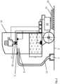
- Fig. 1 shows a side view of an embodiment of a floor cleaning machine according to the invention.
- the floor cleaning machine has a machine frame 1 on which a chassis is provided, of which only the rear wheels 3 are shown in the figures, so that the floor cleaning machine can drive over a floor surface 5 to be cleaned.
- a suction device designed as a suction base 7 is attached to the machine frame 1, with which liquid can be sucked off the floor surface 5 to be cleaned.
- a dirty water tank 9 is attached to the machine frame 1, which has an inlet 11, and the inlet 11 and the suction cup 7 are connected to one another via a dirty water supply line 13.
- the dirty water tank 9 has a lid, and an upward-pointing opening is closed by means of the lid 14 of the dirty water tank 9, which can be pivoted about a pivot axis S, but can be opened by pivoting the lid 14.
- a suction 15 is provided on the lid 14, the suction side of which is connected to the inner volume of the dirty water tank 9 via a suction line 17 and a connection 19 in the lid 14.
- the connection is mounted in a side wall of the dirty water tank 9.
- a cleaning head 21 is held in a height-adjustable manner on a brush pressure adjustment 23. With the help of the brush pressure adjustment 23, it is possible to lower the cleaning head 21 towards the floor surface and lift it away from it.
- the first end position denotes the state in which the cleaning head 21 or an adjusting element, which is movably mounted on the machine frame 1 and is coupled to the cleaning head 21, is lowered onto the floor surface 5 and pressed.
- the second end position denotes the state in which the cleaning head 21 or the adjusting element is lifted off the floor surface.
- the cleaning head 21 is in this exemplary embodiment a scrubber dryer driven in rotation via a motor (not shown) and has brush elements 25 which can engage with the floor surface 5.
- the cleaning head 21 is therefore the brush head of a scrubber dryer.
- the cleaning head 21 represents a sweeping device of a sweeper or the work unit of a polishing machine.
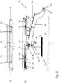
- Figs. 2a and 2b show a side view of the embodiment of the brush pressure adjustment 23, in which the cleaning head 21 is arranged in the second end position, ie in a raised position.
- Fig. 2a shows a holding frame 27 of the brush pressure adjustment, which is adapted to be mounted on the machine frame 1 and on which the in Fig. 2b shown means for raising and lowering the cleaning head 21 are attached.
- FIG. 2a Shows in detail Fig. 2a the holding frame 27 with a first and second guide groove 29, 31, which are aligned parallel to one another and to a longitudinal axis L of the holding frame 27 and spaced apart from one another.
- a first and a second guide element 33, 35 are slidably guided in the guide grooves 29, 31.
- the first guide member 33 is adapted to be connected to a first coupling end (not shown) of an actuator (not shown).
- the second guide member 35 is adapted to be connected to a second coupling end (not shown) of the actuator.
- the actuator has a drive that is designed so that the distance between the first and second coupling ends can be adjusted between a first actuator end position and a second actuator end position. The distance in the first actuator end position is smaller than in the second actuator end position.
- the actuator can, for example, be a linear actuator whose longitudinal axis extends between the first coupling end and the second coupling end.
- An example of a linear actuator is a pneumatic cylinder.
- the linear actuator is slidably mounted on the machine frame 1 or the holding frame 27 in such a way that it can move, for example, along its longitudinal axis relative to the machine frame between two end positions.
- the free movement of the actuator is limited by stop elements in the form of the horizontal limitation of the guide grooves 29, 31.
- one end of the second guide groove 31 points as a stop element towards the first coupling element in the first guide groove 29 and limits a movement of the second coupling element along the longitudinal axis in a direction pointing towards the first coupling element.
- the cleaning head 21 has a cable pull at its upper end 37 with a first end 39a 39 coupled.
- the cable pull 39 is guided over a deflection roller 41 and is coupled to the holding frame 27 at a second end 39b via an eyelet member 43 with an eyelet and a spring 45.
- the spring 45 keeps the cable 39 under tension in all positions of the second guide element 35.
- the eyelet member 43 in turn is guided displaceably in the eyelet ⁇ by the second guide element 35.
- the cleaning head 21 is further coupled at its upper end 37 to a free end 47 of a one-armed lever element 49.
- a fixed end of the lever element 49 is pivotally connected, for example, to the machine frame 1 at a pivot point D, the axis of rotation or pivot axis at the pivot point D preferably running parallel to the floor surface 5 to be cleaned.
- the cleaning head 21 is thus held on the lever element 49 at a distance from the pivot axis D.
- the lever element 49 has an element 53 in an area between its free end 47 and its fixed end 51, which is coupled to the second guide element 33 via a biasing element in the form of a lever spring 55.
- the upper end 37 of the cleaning head 21 and the lever element 49 form an actuating element to which the cleaning head 21 is coupled.
- the actuating element is movably mounted on the machine frame 1 between a first and a second end position and is coupled to the cleaning head 21 in such a way that when the actuating element moves towards the first end position, the cleaning head 21 is lowered and pressed towards the floor surface 5 and that the cleaning head 21 is lifted from the floor surface 5 when the actuating element moves towards the second end position.
- first and second end position of the actuating element is used synonymously with a position of the cleaning head 21 in the embodiment described here.
- This direct transferability results from the direct coupling of the actuating element with the cleaning head 21, which has the upper end of the cleaning head 37.
- the actuating element is coupled to the first coupling end of the actuator via the first guide element 33 in such a way that when the first coupling end moves towards the first actuator end position, the actuating element is subjected to a force that moves the actuating element towards the first final position.
- the actuating element is coupled to the second coupling end of the actuator via the second guide element 35 in such a way that when the second coupling end moves towards the second actuator end position, the actuating element is subjected to a force which moves the actuating element towards the second final position.
- actuating element and the cleaning head 21 coupled to it are positioned in its lifted position, ie in its second end position.
- This second end position results directly from the second actuator end position, in which the coupling ends of the actuator are maximally extended relative to one another.
- the guide elements 33, 35 coupled to the coupling ends are also positioned in the guide grooves 29, 31 at a maximum distance A max from one another.
- the actuating element or the upper end 37 of the cleaning head 21 is subjected to a total force, which results from two essentially the same directed but different strong partial forces with different points of application on the holding frame 27 .
- the first partial force results from the coupling of the second guide element 35 with the eyelet member 43 and the resulting loading of the eyelet member 43 with a force which acts parallel to the spring force of the spring 45 and which acts counter to that coupled by means of the cable 39 via the deflection roller 41
- the weight of the cleaning head 21 acts and lifts the cleaning head 21.
- the second partial force results from the coupling of the upper end 37 of the cleaning head 21 with the lever element 49.
- the weight of the lever element 49 leads to a torque directed in the direction of the bottom surface 5 about the pivot point D, although the lever spring 55 produces this torque depending on the Position of the first guide element 33 and the position of the upper end 37 of the cleaning head 21 is influenced.
- Both partial forces add up in the second actuator end position to form a total force, which results in the cleaning head 21 being lifted off the floor surface 5 to be cleaned.
- Fig. 3 shows the same structure as in Fig. 2 in an intermediate position of the cleaning head 21.
- This intermediate position occurs when the cleaning head 21 moves from the second end position into the first end position, ie the cleaning head 21 is lowered and pressed, or the cleaning head 21 moves from the first end position into the second end position , that is, is withdrawn.
- the actuator is partially retracted.
- Fig. 3a shows, as a result, that the guide elements 33, 35 connected to the coupling ends have a distance A from one another that is smaller than the distance A max in the second actuator end position.
- the main difference to the second actuator end position Fig. 2 is the position of the second guide element 35 and thus the position of the eyelet member 43, to which the cleaning head 21 is connected via the cable pull 39.
- the position of the first actuator end position is the position of the second guide element 35 and thus the position of the eyelet member 43, to which the cleaning head 21 is connected via the cable pull 39.
- the cleaning head 21 is in the intermediate position, as in Fig. 3b shown, lowered onto the floor surface 5, but not pressed.
- the total force results from the weight of the cleaning head 21 and the torque of the lever element 49.
- the now lowered position of the cleaning head 21 and the unchanged position of the first guide element 33 means that the spring 45 and not the guide element 35 generates a tensile force in the cable 39.
- the guide element 35 therefore no longer acts in the intermediate position. Overall, this results in a reduced overall force compared to the second end position.
- Fig. 4 shows the same structure as Fig. 2 and 3 in the first end position of the cleaning head, ie the first actuator end position.
- the actuator is adjusted with the help of the drive in such a way that the two coupling ends and thus the two guide elements 33, 35 in Fig. 4a, b have a minimum distance A min from one another.
- the main difference to the intermediate position is the position of the first guide element 33, which is now positioned such that it applies a tensile force to the element 53 by stretching the second lever spring 55.
- this means that the lever element 49 is coupled to the first coupling end at a distance from the pivot axis in such a way that when the first coupling end moves towards the first actuator end position, a force towards the first end position is exerted on the lever element 49.
- the connection between the first coupling end of the actuator and the lever element 49 has a biasing element in the form of the lever spring 55 on, which is designed to bias the lever element 49 towards the first end position when the first coupling element moves to the first actuator end position.
- FIG. 5 to 7 The embodiment according to the invention is generally explained using schematic principle sketches.
- the Figures 5 to 7 show the three positions that the brush pressure adjustment assumes when the cleaning head 21 is moved from a raised position (second end position) into a lowered and pressed position (first end position). When transitioning from the first end position to the second end position, the brush pressure adjustment assumes the positions in the reverse order.
- Fig. 5 shows an actuator 57 with a first and second coupling end 59, 61.
- the first coupling end 59 is connected to the first guide element 33 and movably received in the first, stationary guide groove 29.
- a fixed connection can be, for example, the connection to the machine frame 1.
- the first guide element 33 is further connected via a first biasing element or the lever spring 55 to an actuating element 63, which has a lever element 49 and the upper end 37 of the cleaning head 21.
- the lever element 49 is designed as a one-armed lever and is mounted stationary at the pivot point D, but pivotable about an axis of rotation about the pivot point D. As already explained, the axis of rotation can, for example, be parallel or essentially parallel to the bottom surface 5.
- the lever element 49 is further rotatably coupled to the upper end 37, preferably rotatable about an axis of rotation that is parallel to the axis of rotation of the lever element 49 at the pivot point D.
- the second coupling end 61 is connected to the second guide element 35.
- the second guide element 35 is also movably accommodated in the second guide groove 31 in a second receptacle 31.
- the second receptacle 31 ' is fixed in place via the second spring 45.
- the second receptacle 31 ' is also connected to the adjusting element 63 at its upper end 37 via the pull cable 39.
- Fig. 5 is the embodiment of the brush pressure adjustment 23 in the second actuator end position, in which the first and second coupling ends 59, 61 have a maximum distance A max from each other.
- the first guide element 33 is in a position relative to the first guide groove 29 in which the movement of the first guide element 33 with the first coupling end 59 is limited by the first guide groove 29.
- the second guide element 35 is in a position relative to the second guide groove 31, which is determined by the maximum travel of the second coupling end 61 of the actuator 57.
- the actuating element or the upper end 37 and thus the cleaning head 21 is subjected to a force via the connection 39, so that the cleaning head 21 is lifted off the floor surface 5.
- the control element is now in the second end position.
- Fig. 6 shows the structure schematically Fig. 5 in an intermediate position.
- the first and second coupling ends 59, 61 are arranged at a distance A from one another which is smaller than the maximum distance A max but larger than the minimum distance A min of the first actuator end position.
- the guide elements 33, 35 are arranged relative to the guide grooves 31, 33 and/or the actuator 57 in such a way that the cleaning head 21 is placed on the bottom surface 5 but is not pressed. In this position, the pressure of the cleaning head 21 can be reduced by the spring 45 if the spring 45 is dimensioned accordingly.
- Fig. 7 finally shows the structure schematically Fig. 6 in the first actuator end position.
- the first and second coupling ends 59, 61 are arranged at a minimum distance A min from one another.
- the position of the actuator 57 is determined in the first actuator end position by the stop 65, against which the second coupling end 61 rests, so that the second coupling end 61 is prevented from moving towards the first coupling end 59.
- the first guide element 33 is positioned relative to the first guide groove 29 in such a way that the first biasing element 55 applies a force to the actuating element 63 or its lever element 49, which presses the cleaning head 21 against the floor surface 5.
- the control element is now in the first end position.
- the second coupling element 61 rests on the stop 65, when the actuator 57 is moved towards the first actuator end position, it cannot move relative to the machine frame 1 towards the first coupling end 59. This means that only the first coupling end 59 can move, which then deforms the lever spring 55 and thus determines the force with which the cleaning head 21 is pressed towards the floor surface 5.
- the vertical position that the cleaning head 21 assumes relative to the floor surface 5 is determined solely by the position of the actuator 57, and the force with which the cleaning head 21 is pressed against the floor surface 5 is set.
- the force that the actuator 57 itself exerts does not have to be controlled. To set this force, it is sufficient to specify the position that the actuator should assume, which also simplifies the structure in terms of control technology.
Landscapes
- Cleaning In General (AREA)
Description
- Die vorliegende Erfindung betrifft eine Bodenreinigungsmaschine mit einem Maschinenrahmen, mit einem an dem Maschinenrahmen angebrachten Fahrwerk zur Bewegung der Bodenreinigungsmaschine über eine zu reinigende Bodenfläche und mit einem Reinigungskopf, der höhenverstellbar am Maschinenrahmen gehaltert ist, sodass der Reinigungskopf hin zu der Bodenfläche abgesenkt und abgehoben werden kann.
- Derartige Bodenreinigungsmaschinen werden dazu verwendet, große Bodenflächen beispielsweise in öffentlichen Gebäuden oder Supermärkten zu reinigen. Dazu werden die Maschinen in der Weise betrieben, dass bei der Fahrt über eine solche zu reinigende Bodenfläche zunächst mit Hilfe des Reinigungskopfes und den daran vorgesehenen, vorzugsweise angetriebenen Bürsten mit von dem Reinigungskopf aufgebrachter Flüssigkeit auf der Bodenfläche vorhandener Schmutz gelöst wird. Mit Hilfe eines Saugfußes wird dann die mit Schmutz beladene Flüssigkeit wieder absaugt. Dabei ist insbesondere der Reinigungskopf höhenverstellbar am Maschinenrahmen der Bodenreinigungsmaschine angebracht, um zu ermöglichen, dass der Reinigungskopf nicht notwendigerweise in Kontakt mit der Bodenfläche ist. Ferner ist der Reinigungskopf auf die zu reinigende Bodenfläche absenkbar. Im Stand der Technik wird für das Anheben und Absenken des Reinigungskopfs in der Regel ein Aktuator verwendet.
- Im Betrieb einer Bodenreinigungsmaschine ist es für einen Bediener wünschenswert, je nach Verschmutzungsgrad der Bodenfläche zwischen wenigstens zwei Andruckstufen des Reinigungskopfs an die Bodenfläche wählen zu können. Beispielsweise kann bei einer normalen Verschmutzung der Reinigungskopf mit einem geringeren Anpressdruck (geringer Anpressdruck) an die Bodenfläche betrieben werden als bei einer stark verschmutzten Bodenfläche (großer Anpressdruck). Üblicherweise wird ein großer Anpressdruck durch ein hohes Eigengewicht des Reinigungskopfs erzeugt. Um diesen jedoch von der Bodenfläche anheben zu können, ist ein entsprechend groß dimensionierter Aktuator notwendig. Somit bestimmt das hohe Eigengewicht des Reinigungskopfs bzw. dessen Gewichtskraft eine untere Kraftgrenze des Aktuators. In diesem Zusammenhang wird unter der die Dimensionierung eines Aktuators eine Wahl einer technischen Ausgestaltung bzw. die technische Ausgestaltung des Aktuators, mit der eine bestimmte Kraft erzeugt wird, verstanden.
- Um die Kraft des Aktuators optimal für die Hubarbeit bzw. die Anpresskraft nutzen zu können, ist eine vertikale Anordnung des Aktuators wünschenswert. Eine solche Anordnung ist häufig jedoch aufgrund eines fehlenden Platzes oberhalb des Bürstenkopfs nicht möglich, da in diesem Bereich typischerweise eine Batterie angeordnet ist. Im Stand der Technik wird dieses Platzproblem daher häufig durch einen schrägen Einbau gelöst, d.h. ein weder waagerechter noch senkrechter Einbau des Aktuators. Nachteilig bei dieser Anordnung des Aktuators ist jedoch, dass der Aktuator eine horizontale Kraftkomponente erzeugt, um die erforderliche Gesamtkraft zu erreichen. Dies hat zur Folge, dass der Aktuator größer als die Gewichtskraft des Reinigungskopfs dimensioniert sein muss, um so die notwendige Gesamtkraft und damit die entsprechende vertikale Kraftkomponente zu erreichen. Ferner ist die horizontale Kraftkomponente ungenutzt. Eine Lösung, bei der ein schräger Einbau des Aktuators vermieden wird, beschreibt die
EP 2 954 817 A1 - Die
EP 2 954 817 A1 offenbart eine Bodenreinigungsmaschine mit einem Maschinenrahmen, wobei an dem Maschinenrahmen ein als elektromechanischer Linearantrieb ausgebildeter Antrieb gehaltert, dessen Kolbenstange geradlinig in einer horizontalen und parallel zur Bodenfläche verlaufenden Richtung verfahrbar ist. An einem freien Ende der Kolbenstange ist ein Verstellelement vorgesehen, das in einer fest am Maschinenrahmen angebrachten Führung geradlinig geführt ist, sodass das Verstellelement eine rein geradlinige Bewegung ausführt. In einer Stellplatte eines Reinigungskopfes ist eine Führungsbahn ausgebildet, die einen ersten Abschnitt und einen zweiten Abschnitt aufweist. Das Verstellelement greift mit einem daran vorgesehenen Zapfen in die Führungsbahn ein. Aufgrund des Verlaufs der Führungsbahn führt eine geradlinige Bewegung der Kolbenstange und damit des Verstellelements zu einer Auf- und Abwärtsbewegung der Stellplatte und damit zu einer Schwenkbewegung der Halterung, sodass durch die geradlinige Bewegung der Kolbenstange bzw. des Verstellelements der Reinigungskopf angehoben bzw. abgesenkt wird. - Die
US 2013/212814 A1 offenbart eine Bodenreinigungsmaschine mit einem Aufhänge- und Hebemechanismus. Der Aufhänge- und Hebemechanismus ist mit verschiedenen Komponenten an einem Rahmen der Bodenreinigungsmaschine befestigt, einschließlich einer Rahmenhalterung, die über eine vertikale Drehachse um den Rahmen schwenkbar ist, und einer Rahmenhalterung, die mit einem Linearantrieb verbunden ist. - Die
US 3 790 981 A offenbart eine Bodenreinigungsmaschine mit einer Besenhalterung. Die Besenhalterung ist über eine Halterung an einem Maschinenrahmen der Bodenreinigungsmaschine befestigt. An der Besenhalterung ist ein Tellerbesen drehbar gelagert. - Demnach ist aus dem Stand der Technik eine Bodenreinigungsmaschine bekannt, die einen Maschinenrahmen, ein an dem Maschinenrahmen angebrachtes Fahrwerk zur Bewegung der Bodenreinigungsmaschine über eine zu reinigende Bodenfläche, einen Reinigungskopf, der höhenverstellbar am Maschinenrahmen gehaltert ist, sodass der Reinigungskopf hin zu der Bodenfläche abgesenkt und davon abgehoben werden kann, ein Stellelement, das zwischen einer ersten und einer zweiten Endstellung beweglich am Maschinenrahmen gehaltert ist und das derart mit dem Reinigungskopf gekoppelt ist, dass der Reinigungskopf bei einer Bewegung des Stellelements hin zu der ersten Endstellung abgesenkt und hin zu der Bodenfläche gepresst wird und dass der Reinigungskopf bei einer Bewegung des Stellelements hin zu der zweiten Endstellung von der Bodenfläche abgehoben wird, und einen Aktuator aufweist, der ein erstes und ein zweites Kopplungsende aufweist, wobei der Aktuator einen Antrieb aufweist, der ausgestaltet ist, dass der Abstand des ersten und zweiten Kopplungsendes zwischen einer ersten Aktuatorendstellung und einer zweiten Aktuatorendstellung eingestellt werden kann.
- Es ist daher Aufgabe der vorliegenden Erfindung, eine eingangs beschriebene Bodenreinigungsmaschine derart auszugestalten, dass für die Positionierung des Reinigungskopfs sowie die Erzeugung des erforderlichen Anpressdrucks auf den Reinigungskopf der entsprechende Aktuator möglichst klein dimensioniert werden kann.
- Die Aufgabe wird gelöst durch eine Bodenreinigungsmaschine mit einem Maschinenrahmen, mit einem an dem Maschinenrahmen angebrachten Fahrwerk zur Bewegung der Bodenreinigungsmaschine über eine zu reinigende Bodenfläche, mit einem Reinigungskopf, der höhenverstellbar am Maschinenrahmen gehaltert ist, sodass der Reinigungskopf hin zu der Bodenfläche abgesenkt und abgehoben werden kann, mit einem Stellelement, das zwischen einer ersten und einer zweiten Endstellung beweglich am Maschinenrahmen gehaltert ist und das derart mit dem Reinigungskopf gekoppelt ist, dass der Reinigungskopf bei einer Bewegung des Stellelements hin zu der ersten Endstellung abgesenkt und hin zu der Bodenfläche gepresst wird und dass der Reinigungskopf bei einer Bewegung des Stellelements hin zu der zweiten Endstellung von der Bodenfläche abgehoben wird, mit einem Aktuator, der ein erstes und ein zweites Kopplungsende aufweist, wobei der Aktuator einen Antrieb aufweist, der ausgestaltet ist, dass der Abstand des ersten und zweiten Kopplungsendes zwischen einer ersten Aktuatorendstellung und einer zweiten Aktuatorendstellung eingestellt werden kann, und wobei bevorzugt der Abstand in der ersten Aktuatorendstellung kleiner als in der zweiten Aktuatorendstellungist, wobei das erste Kopplungsende des Aktuators derart mit dem Stellelement gekoppelt ist, dass bei einer Bewegung des ersten Kopplungsendes hin zu der ersten Aktuatorendstellung das Stellelement mit einer Kraft beaufschlagt wird, die das Stellelement hin zu der ersten Endstellung treibt, und wobei das zweite Kopplungsende des Aktuators derart mit dem Stellelement gekoppelt ist, dass bei einer Bewegung des zweiten Kopplungsendes hin zu der zweiten Aktuatorendstellung das Stellelement mit einer Kraft beaufschlagt wird, die das Stellelement hin zu der zweiten Endstellung treibt.
- Somit weist die Bodenreinigungsmaschine erfindungsgemäß ein Stellelement auf, das zwischen einer ersten und einer zweiten Endstellung beweglich am Maschinenrahmen gehaltert ist. Die Halterung des Stellelements am Maschinenrahmen kann beispielsweise durch ein Hebelelement oder geradlinig verstellbares Element ausgeführt sein. Das Stellelement ist mit dem Reinigungskopf derart gekoppelt, dass der Reinigungskopf bei einer Bewegung des Stellelements hin zu der ersten Endstellung abgesenkt und auf die zu reinigende Bodenfläche gepresst wird. Ferner ist das Stellelement mit dem Reinigungskopf derart gekoppelt, dass der Reinigungskopf bei einer Bewegung des Stellelements hin zu der zweiten Endstellung von der Bodenfläche abgehoben wird.
- Zudem weist die erfindungsgemäße Bodenreinigungsmaschine einen Aktuator auf, der ein erstes und ein zweites Kopplungsende aufweist. Der Aktuator weist wiederum einen Antrieb auf, der derart ausgestaltet ist, dass der Abstand des ersten und zweiten Kopplungsendes zwischen einer ersten Aktuatorendstellung und einer zweiten Aktuatorendstellung eingestellt werden kann. Dabei ist der Abstand in der ersten Aktuatorendstellung vorzugsweise kleiner als in der zweiten Aktuatorendstellung. Der Antrieb kann beispielsweise ein elektrischer, mechanischer, pneumatischer oder jeder andere Antrieb sein, der geeignet ist, den Abstand der beiden Kopplungsenden einzustellen. Ein lediglich zur Veranschaulichung dienendes Beispiel für einen Aktuator ist ein Pneumatikzylinder, bei dem sich ein innerer Abschnitt gegen einen äußeren Abschnitt bei Beaufschlagen des Pneumatikzylinders mit einem geeigneten Druck bewegt bzw. ausfährt. Sowohl der innere als auch der äußere Abschnitt weisen dabei ein Kopplungsende auf. Vorzugsweise ist der Pneumatikzylinder in der ersten Aktuatorendstellung eingefahren und weist eine minimale Länge auf, und in der zweiten Aktuatorendstellung ist der Pneumatikzylinder ausgefahren und weist eine maximale Länge auf. Es ist auch denkbar, dass der Aktuator anders ausgestaltet ist und einen vom Pneumatikzylinder abweichenden Aufbau und/oder Form aufweist. Beispielsweise kann der Aktuator als elektrisch angetriebener Linearaktuator ausgebildet sein.
- Das erste Kopplungsende des Aktuators ist ferner derart mit dem Stellelement gekoppelt, dass bei einer Bewegung des ersten Kopplungsendes hin zu der ersten Aktuatorendstellung das Stellelement mit einer Kraft beaufschlagt wird, die das Stellelement hin zu der ersten Endstellung treibt.
- Mit anderen Worten wird das Stellelement hin zur ersten Aktuatorendstellung durch das erste Kopplungsende derart bewegt, dass der mit dem Stellelement gekoppelte Reinigungskopf in der ersten Endstellung auf die Bodenfläche abgesenkt und daran angepresst wird.
- Das zweite Kopplungsende des Aktuators ist derart mit dem Stellelement gekoppelt, dass bei einer Bewegung des zweiten Kopplungsendes hin zu der zweiten Aktuatorendstellung das Stellelement mit einer Kraft beaufschlagt wird, die das Stellelement hin zu der zweiten Endstellung treibt. Mit anderen Worten wird das Stellelement hin zur zweiten Aktuatorendstellung durch das Kopplungsende derart bewegt, dass der mit dem Stellelement gekoppelte Reinigungskopf bei der Bewegung in die zweite Endstellung von der Bodenfläche abgehoben wird.
- Im Folgenden wird nun die Funktionsweise der erfindungsgemäßen Bodenreinigungsmaschine, insbesondere die Funktion des Absenkens und Anhebens des Reinigungskopfes in Bezug zur reinigenden Bodenfläche beschrieben.
- In der zweiten Endstellung des Stellelements, d.h. der zweiten Aktuatorendstellung, ist der mit dem Stellelement gekoppelte Reinigungskopf von der Bodenfläche abgehoben. In dieser Stellung sind die beiden Kopplungsenden des Aktuators vorzugsweise am weitesten voneinander entfernt. Um den Reinigungskopf nun auf die Bodenfläche abzusenken und anzupressen, wird das erste Kopplungsende des Aktuators zu dem zweiten Kopplungsende des Aktuators mittels des Antriebs verfahren. Bei der Ausführung dieser Bewegung wird der Reinigungskopf zunächst in einer Zwischenstellung auf die Bodenfläche ohne einen zusätzlichen Anpressdruck, d.h. nur durch die eigene Gewichtskraft, aufgesetzt. Werden nun die Kopplungsenden des Aktuators weiter aufeinander zu bewegt, d.h. der Aktuator in die erste Aktuatorendstellung verfahren, wird das Stellelement zunehmend mit einer Kraft beaufschlagt. Diese Kraft führt zu einem zunehmenden Anpressdruck des Reinigungskopfs auf der Bodenfläche. Der Anpressdruck erreicht seinen Höchstwert, wenn der Aktuator die erste Aktuatorendstellung erreicht hat. Um den Reinigungskopf wieder von der Bodenfläche abzuheben, wird umgekehrt vorgegangen und die beiden Kopplungsenden des Aktuators werden hin zu der zweiten Aktuatorendstellung verfahren. Es ist auch denkbar, dass sich beim Verfahren des Aktuators von der zweiten Aktuatorendstellung zu der ersten Aktuatorendstellung der Abstand zwischen den Kopplungsenden vergrößert. In jedem Fall sind jedoch sowohl das erste Kopplungsende als auch das zweite Kopplungsende mit dem mit dem Reinigungskopf verbundenen Stellelement gekoppelt.
- Bei der erfindungsgemäßen Bodenreinigungsmaschine kann das Eigengewicht des Reinigungskopfs im Vergleich zum Stand der Technik geringer gewählt werden. Damit erfolgt die Positionierung und die Steuerung des Anpressdrucks des Reinigungskopfs nicht mehr mit einem hohen Eigengewicht des Reinigungskopfs, sondern im Wesentlichen mit einer Andruckkraft. Bei dem erfindungsgemäßen Aufbau hebt und senkt der Aktuator den leichten Reinigungskopf und ermöglicht ein zusätzliches Anpressen des Reinigungskopfs an die zu reinigende Bodenfläche. Das Anheben des Reinigungskopfs erfolgt in einer ersten Bewegungsrichtung des Aktuators und das Absenken und Anpressen in einer zweiten Bewegungsrichtung. Bei dem erfindungsgemäßen Aufbau erfolgt keine Addition einer hohen Gewichtskraft des Reinigungskopfs mit der Anpresskraft des Reinigungskopfs an die Bodenfläche. Ferner ist aufgrund des geringeren Eigengewichts des Reinigungskopfs zum Anheben nur eine entsprechend geringe Kraft des Aktuators nötig. Dadurch kann die Dimensionierung des Aktuators kleiner gewählt werden.
- In einer Ausführungsform ist der Aktuator ein Linearaktuator, dessen Längsachse sich zwischen dem ersten Kopplungsende und dem zweiten Kopplungsende erstreckt. Die Längsachse beschreibt ferner die Achse, entlang derer der Linearaktuator verfahrbar ist. Ein Beispiel für einen Linearaktuator ist ein Pneumatikzylinder, bei dem sich ein innerer Abschnitt gegen einen äußeren Abschnitt bei Beaufschlagen des Pneumatikzylinders mit einem geeigneten Druck bewegt bzw. ausfährt. Sowohl der innere als auch der äußere Abschnitt weisen dabei jeweils ein Kopplungsende auf. Dabei ist in der ersten Aktuatorendstellung der Pneumatikzylinder eingefahren und weist eine minimale Länge auf, und in der zweiten Aktuatorendstellung ist der Pneumatikzylinder ausgefahren und weist eine maximale Länge auf. Alternativ kann auch ein elektrisch oder hydraulisch angetriebener Linearaktuator verwendet werden.
- Der Vorteil bei der Verwendung von Linearaktuatoren ist, dass diese typischerweise kostengünstige sowie robuste Bauteile sind. Die Verwendung von Linearaktuatoren führt daher zu einer weiteren Vereinfachung des Aufbaus.
- In einer Ausführungsform ist der Linearaktuator derart verschiebbar an dem Maschinenrahmen gehaltert, dass er sich entlang seiner Längsachse relativ zu dem Maschinenrahmen zwischen zwei Endpositionen bewegen kann. Eine solche zum Maschinenrahmen entlang der Längsachse bewegliche Lagerung kann auch als "schwimmende" Lagerung des Linearaktuators beschrieben werden. Durch die schwimmende Lagerung ist es einfach möglich, dass mit nur einem Linearaktuator zwei Kopplungsenden relativ zueinander bewegt werden. Mit anderen Worten erlaubt eine schwimmende Lagerung des Linearaktuators ein Anheben und Absenken des Reinigungskopfes auf die zu reinigende Bodenfläche und eine Beaufschlagung des Reinigungskopfs mit einer variablen Anpresskraft.
- In einer Ausführungsform ist der Abstand der Kopplungsenden in der ersten Aktuatorendstellung kleiner als in der zweiten Aktuatorendstellung, und der Maschinenrahmen weist ein Anschlagelement auf, das zu dem zweiten Kopplungsende weist und eine Bewegung des zweiten Kopplungsendes entlang der Längsachse in einer zu dem ersten Kopplungsende weisenden Richtung begrenzt. Das Anschlagelement dient dem Aktuator beim Bewegen hin zu der ersten Aktuatorendstellung als Widerlager. Diese Begrenzung der Bewegung des zweiten Kopplungendes erlaubt es, dass der Aktuator auf dem Weg in die erste Aktuatorendstellung über das erste Kopplungsende eine Kraft auf das Stellelement in Richtung der ersten Endstellung ausüben kann.
- In einer Ausführungsform, die eine Alternative zu der zuvor genannten Variante bildet, ist der Abstand der Kopplungsenden in der ersten Aktuatorendstellung größer als in der zweiten Aktuatorendstellung, und der Maschinenrahmen weist ein Anschlagelement auf, das zu dem zweiten Kopplungsende weist und eine Bewegung des zweiten Kopplungsendes entlang der Längsachse in einer weg von dem ersten Kopplungsende weisenden Richtung begrenzt. Auch hier dient das Anschlagelement dem Aktuator bei der Bewegung hin zu der ersten Aktuatorendstellung als Widerlager, sodass der Aktuator auch hier auf dem Weg in die erste Aktuatorendstellung über das erste Kopplungsende eine Kraft auf das Stellelement in Richtung der ersten Endstellung ausüben kann.
- In einer weiteren Ausführungsform weist das Stellelement ein Hebelelement auf, wobei das Hebelelement um eine Schwenkachse zwischen der ersten und der zweiten Endstellung schwenkbar mit dem Maschinenrahmen verbunden ist, wobei die Schwenkachse vorzugsweise parallel zu der zu reinigenden Bodenfläche verläuft, wobei der Reinigungskopf beabstandet zu der Schwenkachse an dem Hebelelement gehaltert ist, wobei das Hebelelement derart von der Schwenkachse beabstandet mit dem ersten Kopplungsende gekoppelt ist, dass bei einer Bewegung des ersten Kopplungsendes hin zu der ersten Aktuatorendstellung auf das Hebelelement eine Kraft hin zu der ersten Endstellung ausgeübt wird, und wobei das Hebelelement derart von der Schwenkachse beabstandet mit dem zweiten Kopplungsende gekoppelt ist, dass bei einer Bewegung des zweiten Kopplungsendes hin zu der zweiten Aktuatorendstellung auf das Hebelelement eine Kraft hin zu der zweiten Endstellung ausgeübt wird.
- Das Hebelelement kann beispielsweise als einarmiger oder als zweiarmiger Hebel ausgebildet sein. Es ist auch denkbar, dass die Schwenkachse nicht parallel zur Bodenfläche ausgerichtet ist.
- Die Verwendung eines Hebelelements hat den Vorteil, dass es den gesamten Aufbau weiter vereinfacht.
- In einer weiteren Ausführungsform weist die Verbindung zwischen dem ersten Kopplungsende des Aktuators und dem Hebelelement ein Vorspannelement auf, das ausgestaltet ist, das Hebelelement bei einer Bewegung des ersten Kopplungselements zu der ersten Aktuatorendstellung hin zu der ersten Endstellung vorzuspannen. Das Vorspannelement kann beispielsweise eine Feder aufweisen, die das Hebelelement mit einer Zug- oder Druckkraft beaufschlagt. Das Vorspannelement erfüllt dabei zwei Funktionen. Zum einen wird das Hebelelement mit Hilfe des Vorspannelements vorgegebenen maximalen Anpresskraft beaufschlagt. Zum anderen erlaubt eine Flexibilität des Vorspannelements dem Reinigungskopf eine schnelle Anpassung von dessen vertikaler Position. Eine solche Anpassung kann beispielsweise bei stark unebenen Bodenflächen nötig sein, um den Reinigungskopf ohne Beschädigung über die Bodenfläche bewegen zu können.
- In einer weiteren Ausführungsform ist der Reinigungskopf ein Bürstenkopf und die Bodenreinigungsmaschine eine Scheuersaugmaschine. Es ist aber auch denkbar, dass der Reinigungskopf ein Bürstenkopf einer Kehrmaschine oder einer anderen Art von Bodenreinigungsmaschine ist. Es ist auch denkbar, dass der Reinigungskopf eine Arbeitseinheit einer Poliermaschine ist. Sowohl die Scheuersaugmaschine als auch die Kehrmaschine und die Poliermaschine können dabei handgeführt sein oder mit einem Fahrersitz und/oder -stand ausgeführt sein, von dem man die Bodenreinigungsmaschine bedient, oder sie können autonom arbeiten.
- Im Folgenden wird das erfindungsgemäße Verfahren anhand von lediglich beispielhaften schematischen Zeichnungen beschrieben, wobei
- Fig. 1
- eine seitliche Ansicht einer Ausführungsform der erfindungsgemäßen Bodenreinigungsmaschine zeigt,
- Fig. 2
- einen seitlichen Ausschnitt einer Bürstenandruckverstellung der Ausführungsform in einer abgehobenen Stellung zeigt,
- Fig. 3
- einen seitlichen Ausschnitt der Bürstenandruckverstellung der Ausführungsform in einer abgesenkten, aber nicht angepressten Stellung zeigt,
- Fig. 4
- einen seitlichen Ausschnitt der Bürstenandruckverstellung der Ausführungsform in einer abgesenkten und angepressten Stellung zeigt,
- Fig. 5
- eine schematische Zeichnung der Ausführungsform der erfindungsgemäßen Bürstenandruckverstellung in einer abgehobenen Stellung zeigt,
- Fig. 6
- eine schematische Zeichnung der Ausführungsform der Bürstenandruckverstellung in einer abgesenkten, aber nicht angepressten Stellung zeigt und
- Fig. 7
- eine schematische Zeichnung der Ausführungsform der Bürstenandruckverstellung in einer abgesenkten und angepressten Stellung zeigt.
-
Fig. 1 zeigt eine seitliche Ansicht einer Ausführungsform einer erfindungsgemäßen Bodenreinigungsmaschine. Die Bodenreinigungsmaschine weist einen Maschinenrahmen 1 auf, an dem ein Fahrwerk vorgesehen ist, von dem in den Figuren lediglich die Hinterräder 3 gezeigt sind, sodass die Bodenreinigungsmaschine über eine zu reinigende Bodenfläche 5 fahren kann. Im hinteren Bereich ist an dem Maschinenrahmen 1 eine als Saugfuß 7 ausgebildete Absaugvorrichtung angebracht, mit der Flüssigkeit von der zu reinigenden Bodenfläche 5 abgesaugt werden kann. - Oberhalb des Saugfußes 7 ist an dem Maschinenrahmen 1 ein Schmutzwassertank 9 angebracht, der einen Einlass 11 aufweist, und der Einlass 11 und der Saugfuß 7 sind über eine Schmutzwasserzuleitung 13 miteinander verbunden.
- Der Schmutzwassertank 9 weist einen Deckel auf, und eine nach oben weisende Öffnung ist mittels des um eine Schwenkachse S verschwenkbaren Deckels 14 des Schmutzwassertanks 9 verschlossen, kann aber durch Verschwenken des Deckels 14 geöffnet werden. Oberhalb des Innenvolumens des Schmutzwassertanks 9 ist an dem Deckel 14 eine Absaugung 15 vorgesehen, deren Saugseite über eine Saugleitung 17 und einen Anschluss 19 im Deckel 14 mit dem Innenvolumen des Schmutzwassertanks 9 verbunden ist. Es ist aber auch denkbar, dass der Anschluss in einer Seitenwandung des Schmutzwassertanks 9 angebracht ist.
- Ferner ist bei dem Ausführungsbeispiel in
Fig. 1 an dem Maschinenrahmen 1 noch ein Reinigungskopf 21 höhenverstellbar an einer Bürstenandruckverstellung 23 gehaltert. Mit Hilfe der Bürstenandruckverstellung 23 ist es möglich, den Reinigungskopf 21 hin zu der Bodenfläche abzusenken und davon abzuheben. Dabei bezeichnet die erste Endstellung den Zustand, in dem der Reinigungskopf 21 bzw. ein Stellelement, das beweglich am Maschinenrahmen 1 gehaltert ist und mit dem Reinigungskopf 21 gekoppelt ist, auf die Bodenfläche 5 abgesenkt und angepresst ist. Die zweite Endstellung bezeichnet den Zustand, in dem der Reinigungskopf 21 bzw. das Stellelement von der Bodenfläche abgehoben ist. Der Reinigungskopf 21 wird in diesem Ausführungsbeispiel einer Scheuersaugmaschine über einen Motor (nicht gezeigt) drehend angetrieben und weist Bürstenelemente 25 auf, die mit der Bodenfläche 5 eingreifen können. Der Reinigungskopf 21 ist somit der Bürstenkopf einer Scheuersaugmaschine. Es ist aber auch denkbar, dass der Reinigungskopf 21 eine Kehreinrichtung einer Kehrmaschine oder die Arbeitseinheit einer Poliermaschine darstellt. -
Fig. 2a und 2b zeigen eine seitliche Ansicht der Ausführungsform der Bürstenandruckverstellung 23, in der der Reinigungskopf 21 in der zweiten Endstellung, d.h. in einer abgehobenen Stellung angeordnet ist.Fig. 2a zeigt einen Halterahmen 27 der Bürstenandruckverstellung, der angepasst ist, um an dem Maschinenrahmen 1 montiert zu werden und an dem die inFig. 2b gezeigten Mittel zum Anheben und Absenken des Reinigungskopfs 21 befestigt sind. - Im Detail zeigt
Fig. 2a den Halterahmen 27 mit einer ersten und zweiten Führungsnut 29, 31, die zueinander und zu einer Längsachse L des Halterahmens 27 parallel ausgerichtet und voneinander beabstandet sind. In den Führungsnuten 29, 31 sind ein erstes und ein zweites Führungselement 33, 35 verschiebbar geführt. Das erste Führungselement 33 ist angepasst, um mit einem ersten Kopplungsende (nicht gezeigt) eines Aktuators (nicht gezeigt) verbunden zu werden. Das zweite Führungselement 35 ist angepasst, um mit einem zweiten Kopplungsende (nicht gezeigt) des Aktuators verbunden zu werden. Der Aktuator weist einen Antrieb auf, der ausgestaltet ist, dass der Abstand des ersten und zweiten Kopplungsendes zwischen einer ersten Aktuatorendstellung und einer zweiten Aktuatorendstellung eingestellt werden kann. Dabei ist der Abstand in der ersten Aktuatorendstellung kleiner als in der zweiten Aktuatorendstellung. Der Aktuator kann beispielsweise ein Linearaktuator sein, dessen Längsachse sich zwischen dem ersten Kopplungsende und dem zweiten Kopplungsende erstreckt. Ein Beispiel für einen Linearaktuator ist ein pneumatischer Zylinder. Zudem ist der Linearaktuator derart verschiebbar an dem Maschinenrahmen 1 bzw. dem Halterahmen 27 gehaltert, dass er sich z.B. entlang seiner Längsachse relativ zu dem Maschinenrahmen zwischen zwei Endpositionen bewegen kann. Die freie Bewegung des Aktuators wird durch Anschlagelemente in Form der horizontalen Begrenzung der Führungsnuten 29, 31 begrenzt. Dadurch weist bspw. ein Ende der zweiten Führungsnut 31 als Anschlagelement zu dem ersten Kopplungselement in der ersten Führungsnut 29 hin und begrenzt eine Bewegung des zweiten Kopplungselements entlang der Längsachse in einer zu dem ersten Kopplungselement weisenden Richtung. - In
Fig. 2b ist zu erkennen, wie der Halterahmen 27 und der Reinigungskopf 21 angebracht sind. Der Reinigungskopf 21 ist an seinem oberen Ende 37 mit einem ersten Ende 39a eines Seilzugs 39 gekoppelt. Der Seilzug 39 wird über eine Umlenkrolle 41 geführt und ist an einem zweiten Ende 39b über ein Ösenglied 43 mit einer Öse und einer Feder 45 mit dem Halterahmen 27 gekoppelt. Die Feder 45 hält den Seilzug 39 in allen Positionen des zweiten Führungselements 35 auf Spannung. Das Ösenglied 43 wiederum wird durch das zweite Führungselement 35 in der Öse Ö verschiebbar geführt. Der Reinigungskopf 21 ist ferner an seinem oberen Ende 37 mit einem freien Ende 47 eines einarmigen Hebelelements 49 gekoppelt. Ferner ist ein festes Ende des Hebelelements 49 in einem Drehpunkt D schwenkbar z.B. mit dem Maschinenrahmen 1 verbunden, wobei die Drehachse oder Schwenkachse im Drehpunkt D vorzugsweise parallel zu der zu reinigenden Bodenfläche 5 verläuft. Damit ist der Reinigungskopf 21 beabstandet zu der Schwenkachse D an dem Hebelelement 49 gehaltert. Das Hebelelement 49 weist in einem Bereich zwischen seinem freien Ende 47 und seinem festen Ende 51 ein Element 53 auf, das über ein Vorspannelement in Form einer Hebelfeder 55 mit dem zweiten Führungselement 33 gekoppelt ist. - Das obere Ende 37 des Reinigungskopfs 21 und das Hebelelement 49 bilden ein Stellelement, mit dem der Reinigungskopf 21 gekoppelt ist. Das Stellelement ist zwischen einer ersten und einer zweiten Endstellung beweglich am Maschinenrahmen 1 gehaltert und derart mit dem Reinigungskopf 21 gekoppelt, dass der Reinigungskopf 21 bei einer Bewegung des Stellelements hin zu der ersten Endstellung abgesenkt und hin zu der Bodenfläche 5 gepresst wird und dass der Reinigungskopf 21 bei einer Bewegung des Stellelements hin zu der zweiten Endstellung von der Bodenfläche 5 abgehoben wird.
- Im Folgenden wird der Begriff der ersten und zweiten Endstellung des Stellelements bei der hier beschriebenen Ausführungsform synonym mit einer Stellung des Reinigungskopfs 21 verwendet. Diese direkte Übertragbarkeit ergibt sich aus der direkten Kopplung des Stellelements mit dem Reinigungskopf 21, das das obere Ende des Reinigungskopfs 37 aufweist.
- Zum Verfahren in die erste Endstellung ist das Stellelement über das erste Führungselement 33 mit dem ersten Kopplungsende des Aktuators derart gekoppelt, dass bei einer Bewegung des ersten Kopplungsendes hin zu der ersten Aktuatorendstellung das Stellelement mit einer Kraft beaufschlagt wird, die das Stellelement hin zu der ersten Endstellung treibt. Zum Verfahren in die zweite Endstellung ist das Stellelement über das zweite Führungselement 35 mit dem zweiten Kopplungsende des Aktuators so gekoppelt, dass bei einer Bewegung des zweiten Kopplungsendes hin zu der zweiten Aktuatorendstellung das Stellelement mit einer Kraft beaufschlagt wird, die das Stellelement hin zu der zweiten Endstellung treibt.
- In
Fig. 2 sind das Stellelement und der damit gekoppelte Reinigungskopf 21 in seiner abgehobenen, d.h. in seiner zweiten Endstellung positioniert. Diese zweite Endstellung resultiert direkt aus der zweiten Aktuatorendstellung, in der die Kopplungsenden des Aktuators relativ zueinander maximal ausgefahren sind. Dadurch werden die mit den Kopplungsenden gekoppelten Führungselemente 33, 35 ebenfalls mit einem maximalen Abstand Amax zueinander in den Führungsnuten 29, 31 positioniert. - Als Folge der Anordnung der Führungselemente 33, 35 in der zweiten Aktuatorendstellung wird das Stellelement bzw. das obere Ende 37 des Reinigungskopfs 21 mit einer Gesamtkraft beaufschlagt, die sich aus zwei im Wesentlichen gleich gerichteten, aber unterschiedlich starken Teilkräften mit verschiedenen Angriffspunkten am Halterahmen 27 ergeben. Die erste Teilkraft ergibt sich aus der Kopplung des zweiten Führungselements 35 mit dem Ösenglied 43 und der daraus resultierenden Beaufschlagung des Ösenglieds 43 mit einer Kraft, die parallel zu der Federkraft der Feder 45 wirkt und die entgegen der mittels des Seilzugs 39 über die Umlenkrolle 41 gekoppelten Gewichtskraft des Reinigungskopfs 21 wirkt und den Reinigungskopf 21 anhebt.
- Die zweite Teilkraft ergibt sich aus der Kopplung des oberen Endes 37 des Reinigungskopfs 21 mit dem Hebelelement 49. Die Gewichtskraft des Hebelelements 49 führt zu einem in Richtung der Bodenfläche 5 gerichteten Drehmoment um den Drehpunkt D, wobei jedoch die Hebelfeder 55 dieses Drehmoment abhängig von der Position des ersten Führungselements 33 und der Position des oberen Endes 37 des Reinigungskopfs 21 beeinflusst. Beide Teilkräfte addieren sich in der zweiten Aktuatorendstellung zu einer Gesamtkraft, die zur Folge hat, dass der Reinigungskopf 21 von zu reinigenden Bodenfläche 5 abgehoben ist.
-
Fig. 3 zeigt den gleichen Aufbau wie inFig. 2 in einer Zwischenstellung des Reinigungskopfs 21. Diese Zwischenstellung tritt auf, wenn sich der Reinigungskopf 21 aus der zweiten Endstellung in die erste Endstellung bewegt, d.h. der Reinigungskopf 21 abgesenkt und angepresst wird, oder sich der Reinigungskopf 21 aus der ersten Endstellung in die zweite Endstellung bewegt, d.h. abgehoben wird. In der Zwischenstellung ist der Aktuator zum Teil eingefahren. Dies hat, wieFig. 3a zeigt, zur Folge, dass die mit den Kopplungsenden verbundenen Führungselemente 33, 35 zueinander einen Abstand A haben, der kleiner ist als der Abstand Amax in der zweiten Aktuatorendstellung. Der wesentliche Unterschied zu der zweiten Aktuatorendstellung ausFig. 2 ist die Position des zweiten Führungselements 35 und damit die Position des Ösenglieds 43, mit dem wiederum der Reinigungskopf 21 über den Seilzug 39 verbunden ist. Die Position des ersten - Führungselements 33 ist im Wesentlichen gleich. In der Zwischenstellung ist der Reinigungskopf 21, wie in
Fig. 3b gezeigt, auf die Bodenfläche 5 abgesenkt, jedoch nicht angepresst. - Die Gesamtkraft ergibt sich wie bei der zweiten Endstellung aus der Gewichtskraft des Reinigungskopfs 21 und dem Drehmoment des Hebelelements 49. Jedoch führt die nun abgesenkte Position des Reinigungskopfs 21 und die gleichgebliebene Position des ersten Führungselements 33 dazu, dass nun die Feder 45 und nicht das Führungselement 35 in dem Seilzug 39 eine Zugkraft erzeugt. Im Vergleich mit der zweiten Endstellung wirkt daher das Führungselement 35 in der Zwischenstellung nicht mehr.. In der Summe ergibt sich somit eine im Vergleich mit der zweiten Endstellung verminderte Gesamtkraft.
-
Fig. 4 zeigt den gleichen Aufbau wieFig. 2 und3 in der ersten Endstellung des Reinigungskopfs, d.h. der ersten Aktuatorendstellung. In der ersten Aktuatorendstellung ist der Aktuator mit Hilfe des Antriebs derart eingestellt, dass die beiden Kopplungsenden und damit die beiden Führungselemente 33, 35 inFig. 4a, b einen zueinander minimalen Abstand Amin aufweisen. Der Wesentliche Unterschied zur Zwischenstellung ist die Stellung des ersten Führungselements 33, das nun derart positioniert ist, dass es das Element 53 über eine Dehnung der zweiten Hebelfeder 55 mit einer Zugkraft beaufschlagt. Die Folge davon ist, dass die vom Drehmoment des Hebelelements 49 resultierende Teilkraft auf das obere Ende 37 des Reinigungskopfs 21 im Vergleich zur Zwischenstellung verstärkt wird und das Stellelement bzw. der Reinigungskopf 21 derart an die zu reinigenden Bodenfläche 5 gepresst wird, dass die Bürstenelemente 25 mit der Bodenfläche 5 stärker eingreifen können. Dies wird dadurch erreicht, dass das zweite Führungselement 35 am zu dem ersten Kopplungsende weisenden Ende der zweiten Führungsnut 31 anliegt, wobei dieses Ende einen Anschlag bildet, der verhindert, dass sich das mit dem zweiten Führungselement verbundene zweite Kopplungsende hin zu dem ersten Kopplungsende bewegen kann. Dadurch wird der schwimmend gelagerte gesamte Aktuator an einer Verschiebebewegung gehindert, und das erste Kopplungsende führt bei der Bewegung in die erste Aktuatorendstellung eine Relativbewegung zu dem Maschinenrahmen 1 aus. Dadurch wiederum wird die Hebelfeder 55 gespannt. - Anders ausgedrückt bedeutet dies, dass das Hebelelement 49 derart von der Schwenkachse beabstandet mit dem ersten Kopplungsende gekoppelt ist, dass bei einer Bewegung des ersten Kopplungsendes hin zu der ersten Aktuatorendstellung auf das Hebelelement 49 eine Kraft hin zu der ersten Endstellung ausgeübt wird. Dazu weist die Verbindung zwischen dem ersten Kopplungsende des Aktuators und dem Hebelelement 49 ein Vorspannelement in Form der Hebelfeder 55 auf, das ausgestaltet ist, das Hebelelement 49 bei einer Bewegung des ersten Kopplungselements zu der ersten Aktuatorendstellung hin zu der ersten Endstellung vorzuspannen.
- In den folgenden
Fig. 5 bis 7 wird die erfindungsgemäße Ausführungsform anhand von schematischen Prinzipskizzen allgemein erläutert. DieFiguren 5 bis 7 zeigen die drei Stellungen, die die Bürstenandruckverstellung einnimmt, wenn der Reinigungskopf 21 aus einer abgehobenen Position (zweite Endstellung) in eine abgesenkte und angepresste Position (erste Endstellung) verfahren wird. Beim Übergang von der ersten Endstellung in die zweite Endstellung nimmt die Bürstenandruckverstellung die Stellungen in umgekehrter Reihenfolge an. -
Fig. 5 zeigt einen Aktuator 57 mit einem ersten und zweiten Kopplungsende 59, 61. Das erste Kopplungsende 59 ist mit dem ersten Führungselement 33 verbunden und beweglich in der ersten, ortsfesten Führungsnut 29 aufgenommen. Eine ortsfeste Verbindung kann beispielsweise die Verbindung mit dem Maschinenrahmen 1 sein. Das erste Führungselement 33 ist ferner über ein erstes Vorspannelement bzw. die Hebelfeder 55 mit einem Stellelement 63 verbunden, das ein Hebelelement 49 und das obere Ende 37 des Reinigungskopfs 21 aufweist. Das Hebelelement 49 ist als einarmiger Hebel ausgeführt und an dem Drehpunkt D ortsfest, aber um eine Drehachse um den Drehpunkt D schwenkbar gelagert. Die Drehachse kann, wie schon erläutert, beispielsweise parallel oder im Wesentlichen parallel zu der Bodenfläche 5 sein. Das Hebelelement 49 ist ferner drehbar mit dem oberen Ende 37 gekoppelt, bevorzugt drehbar um eine Drehachse, die parallel zur Drehachse des Hebelelements 49 im Drehpunkt D ist. - Das zweite Kopplungsende 61 ist mit dem zweiten Führungselement 35 verbunden. Das zweite Führungselement 35 ist ebenfalls beweglich in der zweiten Führungsnut 31 in einer zweiten Aufnahme 31 aufgenommen. Die zweite Aufnahme 31' ist über die zweite Feder 45 ortsfest befestigt. Die zweite Aufnahme 31' ist ferner mit dem Stellelement 63 an dessen oberem Ende 37 über das Zugseil 39 verbunden.
- In
Fig. 5 ist die Ausführungsform der Bürstenandruckverstellung 23 in der zweiten Aktuatorendstellung, bei der das erste und zweite Kopplungsende 59, 61 einen maximalen Abstand Amax voneinander aufweisen. In der zweiten Aktuatorendstellung ist das erste Führungselement 33 in einer Position relativ zur ersten Führungsnut 29, in der die Bewegung des ersten Führungselements 33 mit dem ersten Kopplungsende 59 durch die erste Führungsnut 29 begrenzt ist. Ferner ist das zweite Führungselement 35 in einer Position relativ zur zweiten Führungsnut 31, die durch den maximalen Verfahrweg des zweiten Kopplungsendes 61 des Aktuators 57 bestimmt ist. In dieser Position wird das Stellelement bzw. das obere Ende 37 und damit der Reinigungskopf 21 über die Verbindung 39 mit einer Kraft beaufschlagt, so dass der Reinigungskopf 21 von der Bodenfläche 5 abgehoben ist. Das Stellelement ist damit in der zweiten Endstellung. -
Fig. 6 zeigt schematisch den Aufbau ausFig. 5 in einer Zwischenstellung. In der Zwischenstellung sind das erste und zweite Kopplungsende 59, 61 in einem Abstand A zueinander angeordnet, der kleiner als der maximale Abstand Amax, aber größer als der minimale Abstand Amin der ersten Aktuatorendstellung ist. In der Zwischenstellung sind die Führungselemente 33, 35 derart relativ zu den Führungsnuten 31, 33 und/oder dem Aktuator 57 angeordnet, dass der Reinigungskopf 21 auf der Bodenfläche 5 aufgesetzt, jedoch nicht angepresst ist. Der Reinigungskopf 21 kann in dieser Stellung durch die Feder 45 in seinem Andruck zurückgenommen werden, wenn die Feder 45 entsprechend dimensioniert ist. -
Fig. 7 zeigt schließlich schematisch den Aufbau ausFig. 6 in der ersten Aktuatorendstellung. In dieser Stellung sind das erste und zweite Kopplungsende 59, 61 in einem minimalen Abstand Amin zueinander angeordnet. Die Position des Aktuators 57 wird in der ersten Aktuatorendstellung durch den Anschlag 65 bestimmt, an dem das zweite Kopplungsende 61 anliegt, sodass das zweite Kopplungsende 61 an einer Bewegung hin zu dem ersten Kopplungsende 59 gehindert ist. In dieser Aktuatorstellung ist das erste Führungselement 33 derart relativ zur ersten Führungsnut 29 positioniert, dass das erste Vorspannelement 55 das Stellelement 63 bzw. dessen Hebelelement 49 mit einer Kraft beaufschlagt, die den Reinigungskopf 21 an die Bodenfläche 5 anpresst. Das Stellelement befindet sich damit in der ersten Endstellung. Da das zweite Kopplungselement 61 an dem Anschlag 65 anliegt, kann sich dieses, wenn der Aktuator 57 hin zu der ersten Aktuatorendstellung verfahren wird, nicht relativ zu dem Maschinenrahmen 1 hin zu dem ersten Kopplungsende 59 bewegen. Damit kann sich nur das erste Kopplungsende 59 bewegen, das dann die Hebelfeder 55 verformt und damit die Kraft bestimmt, mit der der Reinigungskopf 21 hin zu der Bodenfläche 5 gepresst wird. - Bei dem erfindungsgemäßen Ausführungsform wird somit allein durch die Stellung des Aktuators 57 einerseits die vertikale Position bestimmt, die der Reinigungskopf 21 relativ zu der Bodenfläche 5 einnimmt, und andererseits die Kraft eingestellt, mit der der Reinigungskopf 21 an die Bodenfläche 5 angepresst wird. Dabei muss die Kraft, die der Aktuator 57 selbst ausübt, nicht gesteuert werden. Es ist ausreichend für die Einstellung dieser Kraft, die Position, die der Aktuator einnehmen soll, vorzugeben, was den Aufbau auch steuerungstechnisch vereinfacht.
-
- 1
- Maschinenrahmen
- 3
- Hinterrad
- 5
- Bodenfläche
- 7
- Saugfuß
- 9
- Schmutzwassertank
- 11
- Einlass
- 13
- Schmutzwasserzuleitung
- 14
- Deckel
- 15
- Absaugung
- 17
- Saugleitung
- 19
- Anschluss
- 21
- Reinigungskopf
- 23
- Bürstenandruckverstellung
- 25
- Bürstenelement
- 27
- Halterahmen
- 29
- erste Führungsnut
- 31
- zweite Führungsnut
- 33
- erstes Führungselement
- 35
- zweites Führungselement
- 37
- oberes Ende des Reinigungskopfs
- 39
- Seilzug
- 41
- Umlenkrolle
- 43
- Ösenglied
- 45
- Feder
- 47
- freies Ende des Hebelements
- 49
- Hebelelement
- 51
- festes Ende des Hebelarms
- 53
- Element
- 55
- Hebelfeder
- 57
- Aktuator
- 59
- erstes Kopplungsende
- 61
- zweites Kopplungsende
- 63
- Stellelement
- 65
- Anschlag
Claims (8)
- Bodenreinigungsmaschinemit einem Maschinenrahmen (1),mit einem an dem Maschinenrahmen (1) angebrachten Fahrwerk zur Bewegung der Bodenreinigungsmaschine über eine zu reinigende Bodenfläche (5),mit einem Reinigungskopf (21), der höhenverstellbar am Maschinenrahmen (1) gehaltert ist, sodass der Reinigungskopf (21) hin zu der Bodenfläche (5) abgesenkt und davon abgehoben werden kann,mit einem Stellelement, das zwischen einer ersten und einer zweiten Endstellung beweglich am Maschinenrahmen (1) gehaltert ist und das derart mit dem Reinigungskopf (21) gekoppelt ist, dass der Reinigungskopf (21) bei einer Bewegung des Stellelements hin zu der ersten Endstellung abgesenkt und hin zu der Bodenfläche (5) gepresst wird und dass der Reinigungskopf (21) bei einer Bewegung des Stellelements hin zu der zweiten Endstellung von der Bodenfläche (5) abgehoben wird,mit einem Aktuator (57), der ein erstes und ein zweites Kopplungsende (59, 61) aufweist, wobei der Aktuator (57) einen Antrieb aufweist, der ausgestaltet ist, dass der Abstand des ersten und zweiten Kopplungsendes (59, 61) zwischen einer ersten Aktuatorendstellung und einer zweiten Aktuatorendstellung eingestellt werden kann, dadurch gekennzeichnet, dassdas erste Kopplungsende (59) des Aktuators (57) derart mit dem Stellelement gekoppelt ist, dass bei einer Bewegung des ersten Kopplungsendes (59) hin zu der ersten Aktuatorendstellung das Stellelement mit einer Kraft beaufschlagt wird, die das Stellelement hin zu der ersten Endstellung treibt, undwobei das zweite Kopplungsende (61) des Aktuators (57) derart mit dem Stellelement gekoppelt ist, dass bei einer Bewegung des zweiten Kopplungsendes (61) hin zu der zweiten Aktuatorendstellung das Stellelement mit einer Kraft beaufschlagt wird, die das Stellelement hin zu der zweiten Endstellung treibt.
- Bodenreinigungsmaschine nach Anspruch 1, wobei der Aktuator ein Linearaktuator ist, dessen Längsachse sich zwischen dem ersten Kopplungsende (59) und dem zweiten Kopplungsende (61) erstreckt.
- Bodenreinigungsmaschine nach Anspruch 2, wobei der Linearaktuator (57) derart verschiebbar an dem Maschinenrahmen (1) gehaltert ist, dass er sich entlang seiner Längsachse relativ zu dem Maschinenrahmen (1) zwischen zwei Endpositionen bewegen kann.
- Bodenreinigungsmaschine nach Anspruch 3, wobei der Abstand zwischen dem ersten Kopplungsende (59) und dem zweiten Kopplungsende (61) in der ersten Aktuator-endstellung kleiner als in der zweiten Aktuatorendstellung ist, wobei der Maschinenrahmen (1) ein Anschlagelement (65) aufweist, das zu dem zweiten Kopplungsende (61) weist und eine Bewegung des zweiten Kopplungsendes (61) entlang der Längsachse in einer zu dem ersten Kopplungsende (59) weisenden Richtung begrenzt.
- Bodenreinigungsmaschine nach Anspruch 3, wobei der Abstand zwischen dem ersten Kopplungsende (59) und dem zweiten Kopplungsende (61) in der ersten Aktuator-endstellung größer als in der zweiten Aktuatorendstellung ist, wobei der Maschinenrahmen (1) ein Anschlagelement (65) aufweist, das zu dem zweiten Kopplungsende (61) weist und eine Bewegung des zweiten Kopplungsendes (61) entlang der Längsachse in einer von dem ersten Kopplungsende (59) wegweisenden Richtung begrenzt.
- Bodenreinigungsmaschine nach einem der vorherigen Ansprüche, wobei das Stellelement ein Hebelelement (49) aufweist, wobei das Hebelelement (49) um eine Schwenkachse (D) zwischen der ersten und der zweiten Endstellung schwenkbar mit dem Maschinenrahmen (1) verbunden ist, wobei die Schwenkachse (D) vorzugsweise parallel zu der zu reinigenden Bodenfläche (5) verläuft,wobei der Reinigungskopf (21) beabstandet zu der Schwenkachse (D) an dem Hebelelement (49) gehaltert ist,wobei das Hebelelement (49) derart von der Schwenkachse (D) beabstandet mit dem ersten Kopplungsende (59) gekoppelt ist, dass bei einer Bewegung des ersten Kopplungsendes (59) hin zu der ersten Aktuatorendstellung auf das Hebelelement (49) eine Kraft hin zu der ersten Endstellung ausgeübt wird, undwobei das Hebelelement (49) derart von der Schwenkachse (D) beabstandet mit dem zweiten Kopplungsende (61) gekoppelt ist, dass bei einer Bewegung des zweiten Kopplungsendes (61) hin zu der zweiten Aktuatorendstellung auf das Hebelelement (49) eine Kraft hin zu der zweiten Endstellung ausgeübt wird.
- Bodenreinigungsmaschine nach Anspruch 6, wobei die Verbindung zwischen dem ersten Kopplungsende (59) des Aktuators (57) und dem Hebelelement (49) ein Vorspannelement (55) aufweist, das ausgestaltet ist, das Hebelelement (49) bei einer Bewegung des ersten Kopplungselements (59) zu der ersten Aktuatorendstellung hin zu der ersten Endstellung vorzuspannen.
- Bodenreinigungsmaschine nach einem der vorherigen Ansprüche, wobei der Reinigungskopf (21) ein Bürstenkopf einer Scheuersaugmaschine ist.
Applications Claiming Priority (1)
| Application Number | Priority Date | Filing Date | Title |
|---|---|---|---|
| DE102017111847.0A DE102017111847A1 (de) | 2017-05-30 | 2017-05-30 | Bodenreinigungsmaschine mit Bürstenandruckverstellung |
Publications (2)
| Publication Number | Publication Date |
|---|---|
| EP3417756A1 EP3417756A1 (de) | 2018-12-26 |
| EP3417756B1 true EP3417756B1 (de) | 2023-12-20 |
Family
ID=62196490
Family Applications (1)
| Application Number | Title | Priority Date | Filing Date |
|---|---|---|---|
| EP18172930.2A Active EP3417756B1 (de) | 2017-05-30 | 2018-05-17 | Bodenreinigungsmaschine mit bürstenandruckverstellung |
Country Status (2)
| Country | Link |
|---|---|
| EP (1) | EP3417756B1 (de) |
| DE (1) | DE102017111847A1 (de) |
Families Citing this family (3)
| Publication number | Priority date | Publication date | Assignee | Title |
|---|---|---|---|---|
| DE102019116294A1 (de) * | 2019-06-14 | 2020-12-17 | Norbert Werner | Selbstreinigende Bodenreinigungsmaschine |
| IT202100008120A1 (it) * | 2021-03-31 | 2022-10-01 | Diversey Inc | Apparecchiatura per la pulizia di pavimenti |
| WO2026026733A1 (zh) * | 2024-07-30 | 2026-02-05 | 北京石头世纪科技股份有限公司 | 清洁模组以及清洁设备 |
Family Cites Families (6)
| Publication number | Priority date | Publication date | Assignee | Title |
|---|---|---|---|---|
| US3790981A (en) * | 1972-09-15 | 1974-02-12 | B Young | Surface sweeping machine equipped with gutter brush |
| GB8907481D0 (en) * | 1989-04-03 | 1989-05-17 | Unilever Plc | Floor-cleaning machine |
| DE4123836C1 (en) * | 1991-07-18 | 1992-12-10 | Kuepper-Weisser Gmbh, 7715 Braeunlingen, De | Suspension system for road sweeping equipment - has cylinders connected to roller with pistons to control vertical motion |
| DE102009014560A1 (de) * | 2009-03-16 | 2010-09-23 | Alfred Kärcher Gmbh & Co. Kg | Auswechselbare Kehrbürsteneinrichtung und Kehrmaschine mit einer derartigen Kehrbürsteneinrichtung |
| US9498099B2 (en) * | 2012-02-16 | 2016-11-22 | Tennant Company | Surface maintenance vehicle with compact side brush assembly |
| EP2954817B1 (de) | 2014-06-11 | 2016-10-26 | Hako GmbH | Bodenreinigungsmaschine |
-
2017
- 2017-05-30 DE DE102017111847.0A patent/DE102017111847A1/de not_active Withdrawn
-
2018
- 2018-05-17 EP EP18172930.2A patent/EP3417756B1/de active Active
Also Published As
| Publication number | Publication date |
|---|---|
| EP3417756A1 (de) | 2018-12-26 |
| DE102017111847A1 (de) | 2018-12-06 |
Similar Documents
| Publication | Publication Date | Title |
|---|---|---|
| EP2992803B1 (de) | Selbsttätig verfahrbares bodenreinigungsgerät | |
| EP2954817B1 (de) | Bodenreinigungsmaschine | |
| EP3437942B1 (de) | Fahrzeugwaschanlage und verfahren zu deren betrieb | |
| EP1925540B1 (de) | Hilfsantrieb für einen Anhänger | |
| EP2452664B1 (de) | Operationstisch | |
| EP1964976B1 (de) | Überkopfwerfer-Kehrmaschine | |
| AT516710B1 (de) | Boden-Reinigungseinrichtung | |
| DE19806007A1 (de) | Antrieb für eine automatische Toilettensitzbrille mit Kontaktschutzauflage | |
| EP3231675B1 (de) | Bürstenschwenkvorrichtung, seitenwaschbürste und damit ausgestattete fahrzeugwaschanlage | |
| EP3417756A1 (de) | Bodenreinigungsmaschine mit bürstenandruckverstellung | |
| WO2005037553A1 (de) | Bewegbare gestellteile in einer druckmaschine | |
| WO2022013082A1 (de) | Baugruppe eines fahrzeugsitzes mit einer linearverstelleinrichtung | |
| EP3415067A1 (de) | Seitenbesenanordnung für eine bodenreinigungsmaschine | |
| DE1655604C3 (de) | Vorrichtung zum Steuern der horizontalen Waschbürste in Fahrzeugwaschanlagen | |
| DE102013220149B4 (de) | Bodenreinigungsmaschine mit Transportsicherung für Seitenbesen | |
| EP3403562B1 (de) | Saugfussanordnung für eine bodenreinigungsmaschine und bodenreinigungsmaschine | |
| DE102008029445A1 (de) | Radaufhängung | |
| DE202014104038U1 (de) | Fahrzeugwaschanlage | |
| EP1838198B1 (de) | Feuchtwischer mit einem flächigen halter | |
| DE19613341B4 (de) | Scherenhebetisch | |
| DE102010060878B4 (de) | Verfahren und Vorrichtung zur Aufbringung einer Andrückkraft auf eine Dachwalze | |
| DE2440688B2 (de) | Vorrichtung zur Steuerung der im Spalt zwischen zwei zusammenwirkenden Walzen auf eine durchlaufende Bahn ausgeübten Druckkraft | |
| DE69507132T2 (de) | Vorrichtung zur niveauregulierung und druckanpassung einer kehrwalze in einer industriellen kehrmaschine | |
| DE2111928A1 (de) | Vorrichtung zum Veraendern des Anpressdruckes einer Waschbuerste | |
| DE3012852A1 (de) | Verfahren zur umstellung eines superkalanders auf mattsatinage sowie superkalander zur durchfuehrung des verfahrens |
Legal Events
| Date | Code | Title | Description |
|---|---|---|---|
| PUAI | Public reference made under article 153(3) epc to a published international application that has entered the european phase |
Free format text: ORIGINAL CODE: 0009012 |
|
| STAA | Information on the status of an ep patent application or granted ep patent |
Free format text: STATUS: THE APPLICATION HAS BEEN PUBLISHED |
|
| AK | Designated contracting states |
Kind code of ref document: A1 Designated state(s): AL AT BE BG CH CY CZ DE DK EE ES FI FR GB GR HR HU IE IS IT LI LT LU LV MC MK MT NL NO PL PT RO RS SE SI SK SM TR |
|
| AX | Request for extension of the european patent |
Extension state: BA ME |
|
| STAA | Information on the status of an ep patent application or granted ep patent |
Free format text: STATUS: REQUEST FOR EXAMINATION WAS MADE |
|
| 17P | Request for examination filed |
Effective date: 20190624 |
|
| RBV | Designated contracting states (corrected) |
Designated state(s): AL AT BE BG CH CY CZ DE DK EE ES FI FR GB GR HR HU IE IS IT LI LT LU LV MC MK MT NL NO PL PT RO RS SE SI SK SM TR |
|
| STAA | Information on the status of an ep patent application or granted ep patent |
Free format text: STATUS: EXAMINATION IS IN PROGRESS |
|
| 17Q | First examination report despatched |
Effective date: 20220413 |
|
| GRAP | Despatch of communication of intention to grant a patent |
Free format text: ORIGINAL CODE: EPIDOSNIGR1 |
|
| STAA | Information on the status of an ep patent application or granted ep patent |
Free format text: STATUS: GRANT OF PATENT IS INTENDED |
|
| INTG | Intention to grant announced |
Effective date: 20230705 |
|
| GRAS | Grant fee paid |
Free format text: ORIGINAL CODE: EPIDOSNIGR3 |
|
| GRAA | (expected) grant |
Free format text: ORIGINAL CODE: 0009210 |
|
| STAA | Information on the status of an ep patent application or granted ep patent |
Free format text: STATUS: THE PATENT HAS BEEN GRANTED |
|
| AK | Designated contracting states |
Kind code of ref document: B1 Designated state(s): AL AT BE BG CH CY CZ DE DK EE ES FI FR GB GR HR HU IE IS IT LI LT LU LV MC MK MT NL NO PL PT RO RS SE SI SK SM TR |
|
| REG | Reference to a national code |
Ref country code: GB Ref legal event code: FG4D Free format text: NOT ENGLISH |
|
| REG | Reference to a national code |
Ref country code: DE Ref legal event code: R096 Ref document number: 502018013829 Country of ref document: DE |
|
| REG | Reference to a national code |
Ref country code: CH Ref legal event code: EP |
|
| REG | Reference to a national code |
Ref country code: IE Ref legal event code: FG4D Free format text: LANGUAGE OF EP DOCUMENT: GERMAN |
|
| PG25 | Lapsed in a contracting state [announced via postgrant information from national office to epo] |
Ref country code: GR Free format text: LAPSE BECAUSE OF FAILURE TO SUBMIT A TRANSLATION OF THE DESCRIPTION OR TO PAY THE FEE WITHIN THE PRESCRIBED TIME-LIMIT Effective date: 20240321 |
|
| REG | Reference to a national code |
Ref country code: SE Ref legal event code: TRGR |
|
| REG | Reference to a national code |
Ref country code: LT Ref legal event code: MG9D |
|
| PG25 | Lapsed in a contracting state [announced via postgrant information from national office to epo] |
Ref country code: LT Free format text: LAPSE BECAUSE OF FAILURE TO SUBMIT A TRANSLATION OF THE DESCRIPTION OR TO PAY THE FEE WITHIN THE PRESCRIBED TIME-LIMIT Effective date: 20231220 |
|
| REG | Reference to a national code |
Ref country code: NL Ref legal event code: MP Effective date: 20231220 |
|
| PG25 | Lapsed in a contracting state [announced via postgrant information from national office to epo] |
Ref country code: ES Free format text: LAPSE BECAUSE OF FAILURE TO SUBMIT A TRANSLATION OF THE DESCRIPTION OR TO PAY THE FEE WITHIN THE PRESCRIBED TIME-LIMIT Effective date: 20231220 |
|
| PG25 | Lapsed in a contracting state [announced via postgrant information from national office to epo] |
Ref country code: LT Free format text: LAPSE BECAUSE OF FAILURE TO SUBMIT A TRANSLATION OF THE DESCRIPTION OR TO PAY THE FEE WITHIN THE PRESCRIBED TIME-LIMIT Effective date: 20231220 Ref country code: GR Free format text: LAPSE BECAUSE OF FAILURE TO SUBMIT A TRANSLATION OF THE DESCRIPTION OR TO PAY THE FEE WITHIN THE PRESCRIBED TIME-LIMIT Effective date: 20240321 Ref country code: FI Free format text: LAPSE BECAUSE OF FAILURE TO SUBMIT A TRANSLATION OF THE DESCRIPTION OR TO PAY THE FEE WITHIN THE PRESCRIBED TIME-LIMIT Effective date: 20231220 Ref country code: ES Free format text: LAPSE BECAUSE OF FAILURE TO SUBMIT A TRANSLATION OF THE DESCRIPTION OR TO PAY THE FEE WITHIN THE PRESCRIBED TIME-LIMIT Effective date: 20231220 Ref country code: BG Free format text: LAPSE BECAUSE OF FAILURE TO SUBMIT A TRANSLATION OF THE DESCRIPTION OR TO PAY THE FEE WITHIN THE PRESCRIBED TIME-LIMIT Effective date: 20240320 |
|
| PG25 | Lapsed in a contracting state [announced via postgrant information from national office to epo] |
Ref country code: NL Free format text: LAPSE BECAUSE OF FAILURE TO SUBMIT A TRANSLATION OF THE DESCRIPTION OR TO PAY THE FEE WITHIN THE PRESCRIBED TIME-LIMIT Effective date: 20231220 |
|
| PG25 | Lapsed in a contracting state [announced via postgrant information from national office to epo] |
Ref country code: RS Free format text: LAPSE BECAUSE OF FAILURE TO SUBMIT A TRANSLATION OF THE DESCRIPTION OR TO PAY THE FEE WITHIN THE PRESCRIBED TIME-LIMIT Effective date: 20231220 Ref country code: NO Free format text: LAPSE BECAUSE OF FAILURE TO SUBMIT A TRANSLATION OF THE DESCRIPTION OR TO PAY THE FEE WITHIN THE PRESCRIBED TIME-LIMIT Effective date: 20240320 Ref country code: NL Free format text: LAPSE BECAUSE OF FAILURE TO SUBMIT A TRANSLATION OF THE DESCRIPTION OR TO PAY THE FEE WITHIN THE PRESCRIBED TIME-LIMIT Effective date: 20231220 Ref country code: LV Free format text: LAPSE BECAUSE OF FAILURE TO SUBMIT A TRANSLATION OF THE DESCRIPTION OR TO PAY THE FEE WITHIN THE PRESCRIBED TIME-LIMIT Effective date: 20231220 Ref country code: HR Free format text: LAPSE BECAUSE OF FAILURE TO SUBMIT A TRANSLATION OF THE DESCRIPTION OR TO PAY THE FEE WITHIN THE PRESCRIBED TIME-LIMIT Effective date: 20231220 |
|
| PG25 | Lapsed in a contracting state [announced via postgrant information from national office to epo] |
Ref country code: IS Free format text: LAPSE BECAUSE OF FAILURE TO SUBMIT A TRANSLATION OF THE DESCRIPTION OR TO PAY THE FEE WITHIN THE PRESCRIBED TIME-LIMIT Effective date: 20240420 |
|
| PG25 | Lapsed in a contracting state [announced via postgrant information from national office to epo] |
Ref country code: CZ Free format text: LAPSE BECAUSE OF FAILURE TO SUBMIT A TRANSLATION OF THE DESCRIPTION OR TO PAY THE FEE WITHIN THE PRESCRIBED TIME-LIMIT Effective date: 20231220 |
|
| PG25 | Lapsed in a contracting state [announced via postgrant information from national office to epo] |
Ref country code: SK Free format text: LAPSE BECAUSE OF FAILURE TO SUBMIT A TRANSLATION OF THE DESCRIPTION OR TO PAY THE FEE WITHIN THE PRESCRIBED TIME-LIMIT Effective date: 20231220 |
|
| PG25 | Lapsed in a contracting state [announced via postgrant information from national office to epo] |
Ref country code: SM Free format text: LAPSE BECAUSE OF FAILURE TO SUBMIT A TRANSLATION OF THE DESCRIPTION OR TO PAY THE FEE WITHIN THE PRESCRIBED TIME-LIMIT Effective date: 20231220 Ref country code: SK Free format text: LAPSE BECAUSE OF FAILURE TO SUBMIT A TRANSLATION OF THE DESCRIPTION OR TO PAY THE FEE WITHIN THE PRESCRIBED TIME-LIMIT Effective date: 20231220 Ref country code: RO Free format text: LAPSE BECAUSE OF FAILURE TO SUBMIT A TRANSLATION OF THE DESCRIPTION OR TO PAY THE FEE WITHIN THE PRESCRIBED TIME-LIMIT Effective date: 20231220 Ref country code: IS Free format text: LAPSE BECAUSE OF FAILURE TO SUBMIT A TRANSLATION OF THE DESCRIPTION OR TO PAY THE FEE WITHIN THE PRESCRIBED TIME-LIMIT Effective date: 20240420 Ref country code: EE Free format text: LAPSE BECAUSE OF FAILURE TO SUBMIT A TRANSLATION OF THE DESCRIPTION OR TO PAY THE FEE WITHIN THE PRESCRIBED TIME-LIMIT Effective date: 20231220 Ref country code: CZ Free format text: LAPSE BECAUSE OF FAILURE TO SUBMIT A TRANSLATION OF THE DESCRIPTION OR TO PAY THE FEE WITHIN THE PRESCRIBED TIME-LIMIT Effective date: 20231220 |
|
| PG25 | Lapsed in a contracting state [announced via postgrant information from national office to epo] |
Ref country code: PL Free format text: LAPSE BECAUSE OF FAILURE TO SUBMIT A TRANSLATION OF THE DESCRIPTION OR TO PAY THE FEE WITHIN THE PRESCRIBED TIME-LIMIT Effective date: 20231220 Ref country code: PT Free format text: LAPSE BECAUSE OF FAILURE TO SUBMIT A TRANSLATION OF THE DESCRIPTION OR TO PAY THE FEE WITHIN THE PRESCRIBED TIME-LIMIT Effective date: 20240422 |
|
| PG25 | Lapsed in a contracting state [announced via postgrant information from national office to epo] |
Ref country code: PT Free format text: LAPSE BECAUSE OF FAILURE TO SUBMIT A TRANSLATION OF THE DESCRIPTION OR TO PAY THE FEE WITHIN THE PRESCRIBED TIME-LIMIT Effective date: 20240422 Ref country code: PL Free format text: LAPSE BECAUSE OF FAILURE TO SUBMIT A TRANSLATION OF THE DESCRIPTION OR TO PAY THE FEE WITHIN THE PRESCRIBED TIME-LIMIT Effective date: 20231220 |
|
| REG | Reference to a national code |
Ref country code: DE Ref legal event code: R097 Ref document number: 502018013829 Country of ref document: DE |
|
| PG25 | Lapsed in a contracting state [announced via postgrant information from national office to epo] |
Ref country code: DK Free format text: LAPSE BECAUSE OF FAILURE TO SUBMIT A TRANSLATION OF THE DESCRIPTION OR TO PAY THE FEE WITHIN THE PRESCRIBED TIME-LIMIT Effective date: 20231220 |
|
| PLBE | No opposition filed within time limit |
Free format text: ORIGINAL CODE: 0009261 |
|
| STAA | Information on the status of an ep patent application or granted ep patent |
Free format text: STATUS: NO OPPOSITION FILED WITHIN TIME LIMIT |
|
| PG25 | Lapsed in a contracting state [announced via postgrant information from national office to epo] |
Ref country code: SI Free format text: LAPSE BECAUSE OF FAILURE TO SUBMIT A TRANSLATION OF THE DESCRIPTION OR TO PAY THE FEE WITHIN THE PRESCRIBED TIME-LIMIT Effective date: 20231220 |
|
| PG25 | Lapsed in a contracting state [announced via postgrant information from national office to epo] |
Ref country code: SI Free format text: LAPSE BECAUSE OF FAILURE TO SUBMIT A TRANSLATION OF THE DESCRIPTION OR TO PAY THE FEE WITHIN THE PRESCRIBED TIME-LIMIT Effective date: 20231220 Ref country code: DK Free format text: LAPSE BECAUSE OF FAILURE TO SUBMIT A TRANSLATION OF THE DESCRIPTION OR TO PAY THE FEE WITHIN THE PRESCRIBED TIME-LIMIT Effective date: 20231220 |
|
| 26N | No opposition filed |
Effective date: 20240923 |
|
| REG | Reference to a national code |
Ref country code: CH Ref legal event code: PL |
|
| PG25 | Lapsed in a contracting state [announced via postgrant information from national office to epo] |
Ref country code: MC Free format text: LAPSE BECAUSE OF FAILURE TO SUBMIT A TRANSLATION OF THE DESCRIPTION OR TO PAY THE FEE WITHIN THE PRESCRIBED TIME-LIMIT Effective date: 20231220 |
|
| PG25 | Lapsed in a contracting state [announced via postgrant information from national office to epo] |
Ref country code: LU Free format text: LAPSE BECAUSE OF NON-PAYMENT OF DUE FEES Effective date: 20240517 |
|
| GBPC | Gb: european patent ceased through non-payment of renewal fee |
Effective date: 20240517 |
|
| PG25 | Lapsed in a contracting state [announced via postgrant information from national office to epo] |
Ref country code: MC Free format text: LAPSE BECAUSE OF FAILURE TO SUBMIT A TRANSLATION OF THE DESCRIPTION OR TO PAY THE FEE WITHIN THE PRESCRIBED TIME-LIMIT Effective date: 20231220 Ref country code: LU Free format text: LAPSE BECAUSE OF NON-PAYMENT OF DUE FEES Effective date: 20240517 Ref country code: CH Free format text: LAPSE BECAUSE OF NON-PAYMENT OF DUE FEES Effective date: 20240531 |
|
| REG | Reference to a national code |
Ref country code: BE Ref legal event code: MM Effective date: 20240531 |
|
| PG25 | Lapsed in a contracting state [announced via postgrant information from national office to epo] |
Ref country code: IE Free format text: LAPSE BECAUSE OF NON-PAYMENT OF DUE FEES Effective date: 20240517 |
|
| PG25 | Lapsed in a contracting state [announced via postgrant information from national office to epo] |
Ref country code: BE Free format text: LAPSE BECAUSE OF NON-PAYMENT OF DUE FEES Effective date: 20240531 |
|
| PG25 | Lapsed in a contracting state [announced via postgrant information from national office to epo] |
Ref country code: GB Free format text: LAPSE BECAUSE OF NON-PAYMENT OF DUE FEES Effective date: 20240517 |
|
| PGFP | Annual fee paid to national office [announced via postgrant information from national office to epo] |
Ref country code: DE Payment date: 20250519 Year of fee payment: 8 |
|
| PGFP | Annual fee paid to national office [announced via postgrant information from national office to epo] |
Ref country code: IT Payment date: 20250530 Year of fee payment: 8 |
|
| REG | Reference to a national code |
Ref country code: AT Ref legal event code: MM01 Ref document number: 1641712 Country of ref document: AT Kind code of ref document: T Effective date: 20240517 |
|
| PGFP | Annual fee paid to national office [announced via postgrant information from national office to epo] |
Ref country code: FR Payment date: 20250523 Year of fee payment: 8 |
|
| PG25 | Lapsed in a contracting state [announced via postgrant information from national office to epo] |
Ref country code: AT Free format text: LAPSE BECAUSE OF NON-PAYMENT OF DUE FEES Effective date: 20240517 |
|
| PGFP | Annual fee paid to national office [announced via postgrant information from national office to epo] |
Ref country code: SE Payment date: 20250522 Year of fee payment: 8 |
|
| PG25 | Lapsed in a contracting state [announced via postgrant information from national office to epo] |
Ref country code: CY Free format text: LAPSE BECAUSE OF FAILURE TO SUBMIT A TRANSLATION OF THE DESCRIPTION OR TO PAY THE FEE WITHIN THE PRESCRIBED TIME-LIMIT; INVALID AB INITIO Effective date: 20180517 |
|
| PG25 | Lapsed in a contracting state [announced via postgrant information from national office to epo] |
Ref country code: HU Free format text: LAPSE BECAUSE OF FAILURE TO SUBMIT A TRANSLATION OF THE DESCRIPTION OR TO PAY THE FEE WITHIN THE PRESCRIBED TIME-LIMIT; INVALID AB INITIO Effective date: 20180517 |