EP3415304A1 - Presse sowie verfahren zum betrieb einer presse - Google Patents
Presse sowie verfahren zum betrieb einer presse Download PDFInfo
- Publication number
- EP3415304A1 EP3415304A1 EP18160229.3A EP18160229A EP3415304A1 EP 3415304 A1 EP3415304 A1 EP 3415304A1 EP 18160229 A EP18160229 A EP 18160229A EP 3415304 A1 EP3415304 A1 EP 3415304A1
- Authority
- EP
- European Patent Office
- Prior art keywords
- press
- cylinders
- pressing
- cylinder
- plate
- Prior art date
- Legal status (The legal status is an assumption and is not a legal conclusion. Google has not performed a legal analysis and makes no representation as to the accuracy of the status listed.)
- Granted
Links
Images

Classifications
-
- B—PERFORMING OPERATIONS; TRANSPORTING
- B30—PRESSES
- B30B—PRESSES IN GENERAL
- B30B5/00—Presses characterised by the use of pressing means other than those mentioned in the preceding groups
- B30B5/04—Presses characterised by the use of pressing means other than those mentioned in the preceding groups wherein the pressing means is in the form of an endless band
- B30B5/06—Presses characterised by the use of pressing means other than those mentioned in the preceding groups wherein the pressing means is in the form of an endless band co-operating with another endless band
-
- B—PERFORMING OPERATIONS; TRANSPORTING
- B27—WORKING OR PRESERVING WOOD OR SIMILAR MATERIAL; NAILING OR STAPLING MACHINES IN GENERAL
- B27N—MANUFACTURE BY DRY PROCESSES OF ARTICLES, WITH OR WITHOUT ORGANIC BINDING AGENTS, MADE FROM PARTICLES OR FIBRES CONSISTING OF WOOD OR OTHER LIGNOCELLULOSIC OR LIKE ORGANIC MATERIAL
- B27N3/00—Manufacture of substantially flat articles, e.g. boards, from particles or fibres
- B27N3/08—Moulding or pressing
- B27N3/24—Moulding or pressing characterised by using continuously acting presses having endless belts or chains moved within the compression zone
-
- B—PERFORMING OPERATIONS; TRANSPORTING
- B30—PRESSES
- B30B—PRESSES IN GENERAL
- B30B1/00—Presses, using a press ram, characterised by the features of the drive therefor, pressure being transmitted directly, or through simple thrust or tension members only, to the press ram or platen
- B30B1/32—Presses, using a press ram, characterised by the features of the drive therefor, pressure being transmitted directly, or through simple thrust or tension members only, to the press ram or platen by plungers under fluid pressure
- B30B1/34—Presses, using a press ram, characterised by the features of the drive therefor, pressure being transmitted directly, or through simple thrust or tension members only, to the press ram or platen by plungers under fluid pressure involving a plurality of plungers acting on the platen
Definitions
- the invention relates to a press for pressing material to be pressed, comprising a press frame, an upper press plate in the press upper part and a lower press plate in the press base, wherein the upper press plate and / or the lower press plate with a plurality of (supported on the press frame and) in several rows ( matrix-like) arranged pressing cylinders is acted upon and wherein a plurality of associated with the pressing cylinders control valves are provided.
- the press can basically be a platen press, z.
- a one-day press or multi-day press act which operates in clock mode.
- the invention particularly preferably relates to a continuously operating press for the continuous pressing of pressed material mats, such a continuous press having a heatable upper press plate in the press upper part and a heatable lower press plate in the lower press part and in the upper press part and in the lower press part endlessly circulating press belts, wherein the press belts with interposition supported by WälzSystemaggregaten (eg rolling rods) on the press plates. It is z.
- the upper press plate or the lower press plate for adjusting a press nip formed between the press plates with the press cylinders acted upon.
- the invention relates to a press for pressing mat-shaped pressed material, for. B. of pressed material mats to form plate-shaped materials (pressed slabs).
- This may in particular be a press for the manufacture of wood-based panels, so that mat-shaped spreading material (fibers / chips) is pressed in the press to form a wood-based panel.
- Wood-based panel means in particular chipboard or fiberboard, z. B. MDF board.
- the invention also relates to presses for the processing of other materials, eg. B. for the manufacture of laminate plates, wherein on such a laminate press (which is usually designed as a short-cycle press), stacked pressed material is pressed into laminate plates.
- it may be a press for the production of fiber composites, for. B. an SMC press.
- a press equipped with a plurality of press cylinders arranged in a plurality of rows, each row having a plurality of press cylinders.
- the pressing cylinders are equipped as hydraulic cylinders and consequently connected to a hydraulic system, that is, the hydraulic cylinders are acted upon by control valves with the hydraulic medium, wherein the hydraulic system moreover usually has at least one memory for the hydraulic medium and one or more pumps.
- Such a press for the production of pressed slabs in the embodiment as a continuous press is z. B. from the DE 43 42 279 C1 known.
- the upper press plate is loaded with working cylinder piston assemblies, which are designed as differential cylinder assemblies.
- the cylinders are controlled by means of a control and / or regulating unit via a hydraulic system, wherein the control and / or regulating unit has a computer equipped with a control and / or regulating device and a valve control device for the valves of the hydraulic system.
- the basic structure of the hydraulic system includes in addition to a working high pressure branch for acting on the Häzylinderkolbenanssenen with the working high pressure and a Gegenauch horrzweig that is connected to the same high pressure source, as the working high pressure branch also still a low-pressure control branch, that is, the control of the press cylinder again takes place hydraulically via the control branch, in turn, even belong to a variety of valves. It is in the DE 43 42 279 C1 an embodiment described in which the working cylinder piston assemblies have on the individual press frame to the high pressure source independent hydraulic systems.
- the WO 00/00346 A1 describes a press, which may also be formed as a continuous press, wherein the cylinders of each arranged in series pressing cylinders are arranged in a common cylinder block, wherein the supply lines, hydraulic lines for the pressing cylinder are integrated into the cylinder block.
- the invention has for its object to provide a press of the type described above, which allows a simple configuration a particularly variable operation.
- the invention teaches in a generic press of the type described above that the pressing cylinder, which are preferably arranged like a matrix in a plurality of rows, each equipped with at least one own (arranged directly on the cylinder) control valve, these control valves especially are preferably designed as proportional valves.
- the invention thus solves the hitherto realized in practice principle of centralization and replaces the generally known central hydraulic manifolds, which are equipped with a plurality of control valves, by a plurality of decentralized arranged individual valves, which allow a variable single cylinder control.
- Each press cylinder is therefore associated with at least one control valve, and indeed spatially, that is, the press cylinder itself is equipped with its associated control valve directly.
- This can be z. B. realize that the control valves are each attached directly to the press cylinder, z. B. are screwed. The attachment can be made directly to the cylinder housing of the pressing cylinder, so that the control valve is flanged to the cylinder housing.
- the invention basically includes embodiments in which the pressing cylinders are designed as single-acting plunger cylinders, so that then usually each press cylinder is assigned a single control valve. The same applies to the then optionally provided retraction cylinder, the plunger cylinder on the one hand and the retraction cylinder on the other hand also arranged in a matrix and connected to one of the press plates.
- the invention particularly preferably relates to embodiments in which the pressing cylinders are designed as double-acting differential cylinders with which both compressive forces and tensile forces can be transmitted to the respective press plate.
- double-acting differential cylinders it may be expedient to provide two control valves on each press cylinder, one for the working high pressure and one for the counter-high pressure.
- a differential cylinder can also be operated with only one control valve.
- the invention is characterized overall by an extremely variable single-cylinder control, so that the necessary in the prior art hardware interconnection of individual pressure zones deleted.
- the wiring or interconnection logic is fully variable set electrically via a computer, that is via a so-called electrical matrix can be controlled and adjusted with the help of a computer fully variable each cylinder.
- the control valves distributed in the press for setting variable pressure distributions and pressure profiles with a computer which forms an electrical matrix as it were, individually or in any groups controllable.
- the computer then only has to be electrically or electronically connected to all valves as an electrical matrix, either by wire or wirelessly.
- a continuously operating press is shown in each case, the z. B. can be used for the production of wood-based panels.
- a Pressgutmatte a pressed material mat made of glued stock, continuously pressed using pressure and heat to form a plate or a plate-shaped strand.
- the continuous press has in its basic structure in the press upper part an upper heated press plate 1 and in the lower press part a lower heated press plate 2. Furthermore, in the press upper part and in the lower press part each endlessly circulating press belts z. B. steel bands provided with the interposition of endless rotating WälzSystemaggregaten, z. As rolling rods, are supported on the press plates 1, 2.
- the press has a press frame 3, which in the exemplary embodiment has an upper beam 4 and a lower beam 5 and also a press frame 6 arranged between upper beam and lower beam.
- a press frame 3 which in the exemplary embodiment has an upper beam 4 and a lower beam 5 and also a press frame 6 arranged between upper beam and lower beam.
- Fig. 1 can be seen by way of example that a plurality in the press longitudinal direction successively arranged press frame 6 are provided.
- the presses shown are exemplified as a top piston presses, that is, to the upper press plates 1, a plurality of pressing cylinders 7 are connected, each on the press frame, z. B. are supported on the press frame 6.
- the lower press plate 2 is fixed in the embodiment of a predetermined contour on the press frame.
- Fig. 1 shows an embodiment in which the press plates 1, 2 are formed on the one hand of main press plates in the main press area and on the other hand inlet plates in the inlet region. Both the inlet plates and the main press plates, the already mentioned press cylinder 7 are connected. About the elastic inlet plates is a setting of a variable inlet contour in the inlet region of the press.
- the press cylinders are as it were arranged like a matrix in several rows one behind the other, wherein each individual row of cylinders several press cylinders, z. B. 3 to 6 press cylinder preferably 4 or 5 press cylinder.
- Fig. 2a . b shows an example opposite Fig. 1 modified embodiment in which dispenses with the division into on the one hand inlet plates and on the other hand main press plates. Rather, both the upper press plate 1 and the lower press plate 2 are formed over the entire length with a substantially constant thickness and more preferably over the entire length as a flexible and thus flexurally elastic press plates 1, 2, so that over the press length a particular flexible adjustment of the press nip is possible. It is further indicated that over the entire press length press frame 6 are provided with identical frame thickness. The required rigidity for the operation of different pressure zones is realized in this embodiment by tighter or more frame distances and also by the use of single frame or multiple frame on the other.
- Fig. 2a is indicated that are used over the entire press length and thus both in the compression area and in the main press area pressing cylinder 7 identical design and dimension. This also makes the variety of parts in the in Fig. 2a . b illustrated embodiment reduced.
- the pressing cylinder 7 are designed as double-acting differential cylinders, with the setting of any continuous bending lines both compressive forces and tensile forces on the respective press plates, z. B. the upper press plate 1 can be used up.
- pressure distribution plates 8 are provided in the rear part of the press.
- control valves 9 are attached directly to the respective press cylinder 7, z. B. flanged to the cylinder housing or screwed.
- the press is therefore characterized by a very variable single cylinder control.
- the interconnection logic is no longer produced by hardware control blocks, but exclusively electrically and therefore exclusively via a computer that forms a fully variable electrical matrix for setting any interconnection logic.
- the computer itself is not shown in the figures, but it must be connected only electrically or communication technology with the valves 9. In a separate low-pressure control branch of the hydraulic system for controlling the valves can therefore be omitted. It is only necessary to connect all the control valves 9 via corresponding hydraulic lines with the other components of the hydraulic system, in particular the pumps and the memory. Details are not shown.
- the invention generally also relates to cycle presses, which also have an upper press plate and a lower press plate and a plurality of press cylinders arranged in rows. These can be, in particular, one-floor presses or multi-level presses for the production of wood-based panels or laminate panels and, inter alia, also short-cycle presses in which respectively stacked pressed material is pressed to form a laminate panel.
- the invention also includes embodiments of Production of fiber composites, the z. B. find use in vehicle and aircraft.
Landscapes
- Engineering & Computer Science (AREA)
- Life Sciences & Earth Sciences (AREA)
- Mechanical Engineering (AREA)
- Manufacturing & Machinery (AREA)
- Wood Science & Technology (AREA)
- Forests & Forestry (AREA)
- Physics & Mathematics (AREA)
- Fluid Mechanics (AREA)
- Press Drives And Press Lines (AREA)
- Veneer Processing And Manufacture Of Plywood (AREA)
- Dry Formation Of Fiberboard And The Like (AREA)
- Control Of Presses (AREA)
Abstract
Description
- Die Erfindung betrifft eine Presse zum Verpressen von Pressgut, mit einem Pressengestell, einer oberen Pressenplatte im Pressenoberteil und einer unteren Pressenplatte im Pressenunterteil, wobei die obere Pressenplatte und/oder die untere Pressenplatte mit einer Vielzahl von (am Pressengestell abgestützten und) in mehreren Reihen (matrixartig) angeordneten Presszylindern beaufschlagt ist und wobei eine Vielzahl von mit den Presszylindern verbundenen Steuerventilen vorgesehen sind.
- Bei der Presse kann es sich grundsätzlich um eine Etagenpresse, z. B. eine Einetagenpresse oder Mehretagenpresse handeln, die in Taktbetrieb arbeitet. Besonders bevorzugt betrifft die Erfindung jedoch eine kontinuierlich arbeitende Presse zum kontinuierlichen Verpressen von Pressgutmatten, wobei eine solche kontinuierliche Presse eine beheizbare obere Pressenplatte im Pressenoberteil und eine beheizbare untere Pressenplatte im Pressenunterteil und im Pressenoberteil sowie im Pressenunterteil endlos umlaufende Pressbänder aufweist, wobei die Pressbänder unter Zwischenschaltung von Wälzkörperaggregaten (z. B. Rollstangen) an den Pressenplatten abgestützt ist. Dabei ist z. B. die obere Pressenplatte oder die untere Pressenplatte zur Einstellung eines zwischen den Pressenplatten gebildeten Pressspaltes mit den Presszylindern beaufschlagt.
- Besonders bevorzugt betrifft die Erfindung eine Presse zum Verpressen von mattenförmigem Pressgut, z. B. von Pressgutmatten unter Bildung von plattenförmigen Werkstoffen (Pressgutplatten). Dabei kann es sich insbesondere um eine Presse zum Herstellen von Holzwerkstoffplatten handeln, so dass mattenförmiges Streugut (Fasern/Späne) in der Presse unter Bildung einer Holzwerkstoffplatte verpresst wird. Holzwerkstoffplatte meint insbesondere Spanplatte oder Faserplatte, z. B. MDF-Platte. Die Erfindung betrifft aber auch Pressen für die Verarbeitung anderer Materialien, z. B. zum Herstellen von Laminatplatten, wobei an einer solchen Laminatpresse (die in der Regel als Kurztaktpresse ausgebildet ist), stapelförmiges Pressgut zu Laminatplatten verpresst wird. Ferner kann es sich um eine Presse zur Herstellung von Faserverbundwerkstoffen handeln, z. B. um eine SMC-Presse.
- Stets ist eine Presse gemeint, die mit einer Vielzahl von Presszylindern ausgerüstet ist, die in einer Vielzahl von Reihen angeordnet sind, wobei jede Reihe mehrere Presszylinder aufweist. Die Presszylinder sind als Hydraulikzylinder ausgerüstet und folglich mit einem Hydrauliksystem verbunden, das heißt die Hydraulikzylinder werden über Steuerventile mit dem Hydraulikmedium beaufschlagt, wobei das Hydrauliksystem darüber hinaus üblicherweise zumindest einen Speicher für das Hydraulikmedium und ein oder mehrere Pumpen aufweist.
- Eine solche Presse zur Herstellung von Pressgutplatten in der Ausführungsform als kontinuierliche Presse ist z. B. aus der
DE 43 42 279 C1 bekannt. Die obere Pressenplatte ist mit Arbeitszylinderkolbenanordnungen beaufschlagt, welche als Differenzialzylinderanordnungen ausgebildet sind. Die Zylinder werden mit Hilfe eines Steuer- und/oder Regelaggregates über ein Hydrauliksystem gesteuert, wobei das Steuer und/oder Regelaggregat eine mit einem Rechner ausgerüstete Steuer- und/oder Regeleinrichtung sowie eine Ventilsteuereinrichtung für die Ventile des Hydrauliksystems aufweist. Zum grundsätzlichen Aufbau des Hydrauliksystems gehören neben einem Arbeitshochdruckzweig für die Beaufschlagung der Arbeitszylinderkolbenanordnungen mit dem Arbeitshochdruck und einem Gegenhochdruckzweig, der an die gleiche Hochdruckquelle angeschlossen ist, wie der Arbeitshochdruckzweig außerdem noch ein Niederdruck-Steuerzweig, das heißt die Steuerung der Presszylinder erfolgt wiederum hydraulisch über den Steuerzweig, dem wiederum selbst eine Vielzahl von Ventilen angehören. Dabei wird in derDE 43 42 279 C1 eine Ausführungsform beschrieben, bei der die Arbeitszylinderkolbenanordnungen an den einzelnen Pressenrahmen bis auf die Hochdruckquelle selbstständige Hydrauliksysteme aufweisen. - Aus der
DE 39 14 105 A1 ist im Übrigen eine Ausführungsform einer kontinuierlichen Presse bekannt, bei der an die eine Pressenplatte (z. B. die obere Pressenplatte) z. B. einerseits Presszylinder als Plungerzylinder und andererseits als Rückzugszylinder angeschlossen sind. - Die
WO 00/00346 A1 - In der Praxis ist es bislang z. B. bei kontinuierlich arbeitenden Pressen, die z. B. in der Holzwerkstoffindustrie eingesetzt werden, üblich, die Vielzahl von Ventilen, die (strömungstechnisch) z. B. über Leitungen mit den zahlreichen Presszylindern verbunden sind, zu zentralisieren und in einem gemeinsamen Ventilblock bzw. Hydraulikverteilerblock zusammenzufassen. Die einzelnen Ventile sind dabei fest vorgegeben über Bohrungen logisch miteinander verkettet, so dass in der Praxis über solche Hydraulikverteilerblöcke gleichsam hardwaremäßig eine feste Verschaltung vorgegeben ist. Der Einsatz solcher Hydraulikverteilerblöcke hat sich in der Praxis grundsätzlich bewährt, denn das System ist wartungs- und montagefreundlich und arbeitet sehr zuverlässig. Insgesamt haben sich Pressen und insbesondere kontinuierliche Pressen der eingangs beschriebenen Art seit Jahrzehnten hervorragend bewährt, sie sind jedoch weiterentwicklungsfähig. - Hier setzt die Erfindung ein.
- Der Erfindung liegt die Aufgabe zugrunde, eine Presse der eingangs beschriebenen Art zu schaffen, die bei einfachem Aufbau einen besonders variablen Betrieb ermöglicht.
- Zur Lösung dieser Aufgabe lehrt die Erfindung bei einer gattungsgemäßen Presse der eingangs beschrieben Art, dass die Presszylinder, die bevorzugt matrixartig in einer Vielzahl von Reihen angeordnet sind, mit jeweils zumindest einen eigenen (direkt am Zylinder angeordneten) Steuerventil ausgerüstet sind, wobei diese Steuerventile besonders bevorzugt als Proportionalventile ausgebildet sind.
- Die Erfindung löst sich folglich von dem bislang in der Praxis realisierten Prinzip der Zentralisierung und ersetzt die grundsätzlich bekannten zentralen Hydraulikverteilerblöcke, die mit einer Vielzahl von Steuerventilen ausgerüstet sind, durch eine Vielzahl von dezentral angeordneten Einzelventilen, die eine variable Einzelzylindersteuerung ermöglichen. Jedem Presszylinder ist folglich zumindest ein eigenes Steuerventil zugeordnet und zwar auch räumlich, das heißt, der Presszylinder selbst ist mit dem ihm zugeordneten Steuerventil unmittelbar ausgerüstet. Dieses lässt sich z. B. dadurch realisieren, dass die Steuerventile jeweils unmittelbar an dem Presszylinder befestigt sind, z. B. verschraubt sind. Die Befestigung kann unmittelbar an dem Zylindergehäuse des Presszylinders erfolgen, so dass das Steuerventil an das Zylindergehäuse angeflanscht ist.
- Die Erfindung umfasst grundsätzlich Ausführungsformen bei denen die Presszylinder als einfach wirkende Plungerzylinder ausgebildet sind, so dass dann in der Regel jedem Presszylinder ein einzelnes Steuerventil zugeordnet ist. Gleiches gilt für die dann gegebenenfalls vorgesehenen Rückzugszylinder, wobei die Plungerzylinder einerseits und die Rückzugszylinder andererseits ebenfalls matrixartig angeordnet und an eine der Pressenplatten angeschlossen sein können.
- Besonders bevorzugt betrifft die Erfindung jedoch Ausführungsformen, bei denen die Presszylinder als doppeltwirkende Differenzialzylinder ausgebildet sind, mit denen sowohl Druckkräfte als auch Zugkräfte auf die jeweilige Pressenplatte übertragen werden können. Bei solchen doppelwirkenden Differenzialzylindern kann es zweckmäßig sein, an jedem Presszylinder jeweils zwei Steuerventile vorzusehen, eines für den Arbeitshochdruck und eines für den Gegenhochdruck. Grundsätzlich lässt sich ein Differentialzylinder aber auch mit lediglich einem Steuerventil betreiben.
- Die Erfindung zeichnet sich insgesamt durch eine äußerst variable Einzelzylinderansteuerung aus, so dass die beim Stand der Technik notwendige hardwaremäßige Verschaltung einzelner Druckzonen entfällt. Die Verschaltung bzw. Verschaltungslogik wird vollvariabel elektrisch über einen Rechner eingestellt, das heißt über eine gleichsam elektrische Matrix kann mit Hilfe eines Rechners voll variabel jeder einzelne Zylinder angesteuert und eingestellt werden. In bevorzugter Weiterbildung sind folglich die in der Presse verteilten Steuerventile zur Einstellung variabler Druckverteilungen und Druckprofile mit einem Rechner, der gleichsam eine elektrische Matrix bildet, einzeln oder auch in beliebigen Gruppen ansteuerbar. Der Rechner muss dann als elektrische Matrix nur elektrisch bzw. elektronisch mit sämtlichen Ventilen verbunden sein, und zwar entweder drahtgebunden oder auch drahtlos. Darüber hinaus ist es lediglich erforderlich, sämtliche dezentral an den jeweiligen Zylindern angeordneten Steuerventile über Hydraulikleitungen mit den übrigen Komponenten des Hydrauliksystems, insbesondere dem Speicher und den Pumpen zu verbinden.
- Im Folgenden wird die Erfindung anhand einer lediglich ein Ausführungsbeispiel darstellenden Zeichnung näher erläutert. Es zeigen
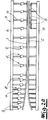
- Fig. 1
- eine kontinuierlich arbeitende Presse in einer Seitenansicht und
- Fig. 2a
- (vereinfacht) eine abgewandelte Ausführungsform einer kontinuierlich arbeitenden Presse,
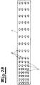
- Fig. 2b
- eine Ansicht von oben auf die obere Presseplatte der Presse nach
Fig. 2a . - In den Figuren ist jeweils eine kontinuierlich arbeitende Presse dargestellt, die z. B. für die Herstellung von Holzwerkstoffplatten einsetzbar ist. In dieser kontinuierlichen Presse wird eine Pressgutmatte, z. B. eine aus beleimten Streugut hergestellte Pressgutmatte, kontinuierlich unter Anwendung von Druck und Wärme unter Bildung einer Platte bzw. eines plattenförmigen Strangs verpresst.
- Die kontinuierliche Presse weist in Ihrem grundsätzlichen Aufbau im Pressenoberteil eine obere beheizte Pressenplatte 1 und im Pressenunterteil eine untere beheizte Pressenplatte 2 auf. Ferner sind im Pressenoberteil und im Pressenunterteil jeweils endlos umlaufende Pressbänder z. B. Stahlbänder vorgesehen, die unter Zwischenschaltung von endlos umlaufenden Wälzkörperaggregaten, z. B. Rollstangen, an den Pressenplatten 1, 2 abgestützt sind.
- Ferner weist die Presse ein Pressengestell 3 auf, das im Ausführungsbeispiel einen Oberholm 4 und einen Unterholm 5 sowie zwischen Oberholm und Unterholm angeordnete Pressenrahmen 6 aufweist. In
Fig. 1 ist beispielhaft erkennbar, dass eine Vielzahl in Pressenlängsrichtung hintereinander angeordnete Pressenrahmen 6 vorgesehen sind. - Die dargestellten Pressen sind beispielhaft als Oberkolbenpressen ausgebildet, das heißt an die oberen Pressenplatten 1 sind eine Vielzahl von Presszylindern 7 angeschlossen, die jeweils an dem Pressengestell, z. B. an dem Pressenrahmen 6 abgestützt sind. Die untere Pressenplatte 2 ist im Ausführungsbeispiel einer festgelegten Kontur an dem Pressengestell befestigt.
-
Fig. 1 zeigt dabei eine Ausführungsform, bei der die Pressenplatten 1, 2 einerseits von Hauptpressenplatten im Hauptpressbereich und andererseits Einlaufplatten im Einlaufbereich gebildet werden. Sowohl an die Einlaufplatten als auch an die Hauptpressenplatten sind die bereits erwähnten Presszylinder 7 angeschlossen. Über die elastischen Einlaufplatten erfolgt eine Einstellung einer variablen Einlaufkontur im Einlaufbereich der Presse. Die Presszylinder sind gleichsam matrixartig in mehreren Reihen hintereinander angeordnet, wobei jede einzelne Zylinderreihe mehrere Presszylinder, z. B. 3 bis 6 Presszylinder vorzugsweise 4 oder 5 Presszylinder aufweist. -
Fig. 2a ,b zeigt beispielhaft eine gegenüberFig. 1 abgewandelte Ausführungsform, bei der auf die Aufteilung in einerseits Einlaufplatten und andererseits Hauptpressenplatten verzichtet wird. Vielmehr sind sowohl die obere Pressenplatte 1 als auch die untere Pressenplatte 2 über die gesamte Länge mit einer im Wesentlichen konstanten Dicke ausgebildet und besonders bevorzugt über die gesamten Länge als flexible und folglich biegeelastische Pressenplatten 1, 2 ausgebildet, so dass über die Pressenlänge eine besonders flexible Einstellung des Pressspaltes möglich ist. Dabei ist ferner angedeutet, dass über die gesamte Pressenlänge Pressenrahmen 6 mit identischer Rahmenstärke vorgesehen sind. Die erforderliche Steifigkeit zur Bedienung unterschiedlicher Druckzonen wird bei dieser Ausführungsform durch engere oder weitere Rahmenabstände und außerdem durch den Einsatz von Einfachrahmen oder Mehrfachrahmen andererseits realisiert. So ist erkennbar, dass im Einlaufbereich Doppelrahmen realisiert sind, die jeweils aus den Einzelrahmen identischer Stärke zusammengesetzt sind. Die ebenfalls vorgesehenen Pressbänder, die über z. B. Rollstangen an den Pressenplatten 1, 2 abgestützt sind, und welche das Pressgut durch die Presse führen, sind inFig. 2a nicht dargestellt. - In
Fig. 2a ist angedeutet, dass über die gesamte Pressenlänge und folglich sowohl im Verdichtungsbereich als auch im Hauptpressbereich Presszylinder 7 identischer Bauart und Dimension verwendet werden. Auch dadurch wird die Teilevielfalt bei der inFig. 2a ,b dargestellten Ausführungsform reduziert. In dem dargestellten Ausführungsbeispiel sind die Presszylinder 7 als doppeltwirkende Differenzialzylinder ausgebildet, mit den zur Einstellung beliebiger kontinuierlicher Biegelinien sowohl Druckkräfte als auch Zugkräfte auf die jeweilige Pressenplatten, z. B. die oberen Pressenplatte 1 aufgebraucht werden können. - Es ist ferner erkennbar, dass im hinteren Teilbereich der Presse Druckverteilplatten 8 vorgesehen sind.
- Sowohl nach der Ausführungsform nach
Fig. 1 als auch nach der Ausführungsform nachFig. 2a ,b sind nun erfindungsgemäß die Presszylinder 7 der Presse selbst mit jeweils zumindest einem eigenen Steuerventil 9 ausgerüstet, wobei die Steuerventile 9 als Proportionalventile ausgebildet sind. - Es ist lediglich angedeutet, dass die Steuerventile 9 unmittelbar an dem jeweiligen Presszylinder 7 befestigt sind, z. B. an dessen Zylindergehäuse angeflanscht bzw. angeschraubt sind.
- Die Presse zeichnet sich folglich durch eine sehr variable Einzelzylinderansteuerung aus. Die Verschaltungslogik wird nicht mehr durch hardwaremäßig vorgegebene Steuerblöcke hergestellt, sondern ausschließlich elektrisch und folglich ausschließlich über einen Rechner, der eine vollkommen variable elektrische Matrix zur Einstellung einer beliebigen Verschaltungslogik bildet. Der Rechner selbst ist in den Figuren nicht dargestellt, er muss jedoch lediglich elektrisch bzw. kommunikationstechnisch mit den Ventilen 9 verbunden werden. Auf einen separaten Niederdrucksteuerzweig des Hydrauliksystems zur Steuerung der Ventile kann folglich verzichtet werden. Es ist lediglich erforderlich sämtliche Steuerventile 9 über entsprechende Hydraulik-Leitungen mit den übrigen Komponenten des Hydrauliksystems, insbesondere die Pumpen und den Speicher zu verbinden. Einzelheiten dazu sind nicht dargestellt.
- In den Figuren sind im Übrigen lediglich Ausführungsformen einer kontinuierlich arbeitenden Presse dargestellt, die von der Erfindung besonders bevorzugt umfasst sind. Die Erfindung betrifft grundsätzlich aber auch Taktpressen, die ebenfalls über eine obere Pressenplatte und eine untere Pressenplatte und über eine Vielzahl von in Reihen angeordneten Presszylindern aufweisen. Dabei kann es sich insbesondere um Einetagenpressen oder Mehretagenpresen zur Herstellung von Holzwerkstoffplatten oder Laminatplatten und unter anderem auch Kurztaktpressen handeln, bei denen jeweils stapelförmiges Pressgut unter Bildung einer Laminatplatte verpresst wird. Darüber hinaus umfasst die Erfindung ebenfalls Ausführungsformen zur Herstellung von Faserverbundwerkstoffen, die z. B. im Fahrzeugbau und Flugzeugbau Einsatz finden.
Claims (6)
- Presse zum Verpressen von Pressgut,
mit einem Pressengestell (3), einer oberen Pressenplatte (1) im Pressenoberteil und einer unteren Pressenplatte (2) im Pressenunterteil,
wobei die obere Pressenplatte (1) und/oder die untere Pressenplatte (2) mit einer Vielzahl von in mehreren Reihen angeordneten Presszylindern (7) beaufschlagt ist und
wobei eine Vielzahl von mit den Presszylindern (7) verbundenen Steuerventilen (9) vorgesehen sind,
dadurch gekennzeichnet, dass die Presszylinder (7) mit jeweils zumindest einem eigenen, an dem Presszylinder angeordneten Steuerventil (9) ausgerüstet sind. - Presse nach Anspruch 1, dadurch gekennzeichnet, dass die Steuerventile (9) als Proportionalventile ausgebildet sind.
- Presse nach Anspruch 1 oder 2, dadurch gekennzeichnet, dass die Steuerventile (9) unmittelbar an dem jeweiligen Presszylinder (7), z. B. an dessen Zylindergehäuse befestigt sind, z. B. verschraubt sind.
- Presse nach einem der Ansprüche 1 bis 3, dadurch gekennzeichnet, dass die in der Presse verteilten Steuerventile (9) zur Einstellung variabler Druckverteilungen und Druckprofile mit einem Rechner einzeln oder auch in beliebigen Gruppen ansteuerbar sind.
- Presse nach einem der Ansprüche 1 bis 4 in der Ausführungsform einer kontinuierlichen Presse zum Verpressen von Pressgutmatten, insbesondere im Zuge der Herstellung von Holzwerkstoffplatten oder dergleichen Werkstoffplatten
mit einer beheizbaren oberen Pressenplatte (1) im Pressenoberteil und einer beheizbare unteren Pressenplatte (2) im Pressenunterteil,
mit im Pressenoberteil und im Pressenunterteil endlos umlaufenden Pressbändern, die unter Zwischenschaltung von Wälzkörperaggregaten an den Pressenplatten (1, 2) abgestützt sind. - Verfahren zum Betrieb einer Presse nach einem der Ansprüche 1 bis 5, dadurch gekennzeichnet, dass die Presszylinder über einen mit den Steuerventilen verbundenen Rechner einzeln oder variabel in beliebigen Gruppen angesteuert werden.
Applications Claiming Priority (1)
| Application Number | Priority Date | Filing Date | Title |
|---|---|---|---|
| DE102017110882.3A DE102017110882B4 (de) | 2017-05-18 | 2017-05-18 | Presse |
Publications (2)
| Publication Number | Publication Date |
|---|---|
| EP3415304A1 true EP3415304A1 (de) | 2018-12-19 |
| EP3415304B1 EP3415304B1 (de) | 2023-07-12 |
Family
ID=61581000
Family Applications (1)
| Application Number | Title | Priority Date | Filing Date |
|---|---|---|---|
| EP18160229.3A Active EP3415304B1 (de) | 2017-05-18 | 2018-03-06 | Presse sowie verfahren zum betrieb einer presse |
Country Status (3)
| Country | Link |
|---|---|
| EP (1) | EP3415304B1 (de) |
| CN (1) | CN108943319A (de) |
| DE (1) | DE102017110882B4 (de) |
Families Citing this family (3)
| Publication number | Priority date | Publication date | Assignee | Title |
|---|---|---|---|---|
| DE102023136272A1 (de) * | 2023-12-21 | 2025-06-26 | Siempelkamp Maschinen- Und Anlagenbau Gmbh | Verfahren zur Herstellung einer Werkstoffplatte |
| DE102023136271A1 (de) * | 2023-12-21 | 2025-06-26 | Siempelkamp Maschinen- Und Anlagenbau Gmbh | Verfahren zur Herstellung einer Werkstoffplatte |
| DE102023136273A1 (de) * | 2023-12-21 | 2025-06-26 | Siempelkamp Maschinen- Und Anlagenbau Gmbh | Verfahren zur Herstellung einer Werkstoffplatte |
Citations (6)
| Publication number | Priority date | Publication date | Assignee | Title |
|---|---|---|---|---|
| US4697338A (en) * | 1984-08-31 | 1987-10-06 | Bobst Sa | Device for preparing a cutting tool |
| US5103172A (en) * | 1989-04-08 | 1992-04-07 | Festo Kg | Piston and cylinder device with fixed conductive guide on periphery of cylinder |
| DE4342279C1 (de) * | 1993-12-11 | 1995-01-12 | Siempelkamp Gmbh & Co | Kontinuierliche Presse für die Herstellung von Spanplatten, Faserplatten, Laminatplatten und ähnlichen Preßgutplatten |
| DE102010003368A1 (de) * | 2010-03-26 | 2011-09-29 | Dieffenbacher Gmbh + Co. Kg | Verfahren zur Herstellung von Werkstoffplatten in einer kontinuierlich arbeitende Presse und eine kontinuierlich arbeitende Presse |
| DE102012102594A1 (de) * | 2012-03-26 | 2013-09-26 | Siempelkamp Maschinen- Und Anlagenbau Gmbh & Co. Kg | Hydraulische Taktpresse |
| US20140083314A1 (en) * | 2011-05-27 | 2014-03-27 | Klaus Schuermann | Cycle press |
Family Cites Families (5)
| Publication number | Priority date | Publication date | Assignee | Title |
|---|---|---|---|---|
| DE3914105A1 (de) * | 1989-04-28 | 1990-10-31 | Siempelkamp Gmbh & Co | Pressanlage zum kontinuierlichen pressen von pressgutbahnen |
| JP3092460B2 (ja) * | 1994-09-14 | 2000-09-25 | 株式会社日立製作所 | 幅圧縮加工機及び圧延機 |
| DE19828822C1 (de) * | 1998-06-27 | 1999-09-30 | Siempelkamp Gmbh & Co | Presse, insbesondere kontinuierliche Presse |
| DE102008061835B3 (de) * | 2008-12-11 | 2009-12-03 | Kraussmaffei Technologies Gmbh | Doppelbandpresse |
| CN203900181U (zh) * | 2014-05-23 | 2014-10-29 | 兰州兰石集团有限公司 | 四辊卷板机下辊、侧辊同步升降控制系统 |
-
2017
- 2017-05-18 DE DE102017110882.3A patent/DE102017110882B4/de not_active Expired - Fee Related
-
2018
- 2018-03-06 EP EP18160229.3A patent/EP3415304B1/de active Active
- 2018-05-16 CN CN201810464544.1A patent/CN108943319A/zh active Pending
Patent Citations (6)
| Publication number | Priority date | Publication date | Assignee | Title |
|---|---|---|---|---|
| US4697338A (en) * | 1984-08-31 | 1987-10-06 | Bobst Sa | Device for preparing a cutting tool |
| US5103172A (en) * | 1989-04-08 | 1992-04-07 | Festo Kg | Piston and cylinder device with fixed conductive guide on periphery of cylinder |
| DE4342279C1 (de) * | 1993-12-11 | 1995-01-12 | Siempelkamp Gmbh & Co | Kontinuierliche Presse für die Herstellung von Spanplatten, Faserplatten, Laminatplatten und ähnlichen Preßgutplatten |
| DE102010003368A1 (de) * | 2010-03-26 | 2011-09-29 | Dieffenbacher Gmbh + Co. Kg | Verfahren zur Herstellung von Werkstoffplatten in einer kontinuierlich arbeitende Presse und eine kontinuierlich arbeitende Presse |
| US20140083314A1 (en) * | 2011-05-27 | 2014-03-27 | Klaus Schuermann | Cycle press |
| DE102012102594A1 (de) * | 2012-03-26 | 2013-09-26 | Siempelkamp Maschinen- Und Anlagenbau Gmbh & Co. Kg | Hydraulische Taktpresse |
Also Published As
| Publication number | Publication date |
|---|---|
| EP3415304B1 (de) | 2023-07-12 |
| DE102017110882B4 (de) | 2019-10-31 |
| DE102017110882A1 (de) | 2018-11-22 |
| CN108943319A (zh) | 2018-12-07 |
Similar Documents
| Publication | Publication Date | Title |
|---|---|---|
| DE4340982B4 (de) | Kontinuierlich arbeitende Presse | |
| DE4342279C1 (de) | Kontinuierliche Presse für die Herstellung von Spanplatten, Faserplatten, Laminatplatten und ähnlichen Preßgutplatten | |
| EP0909620B1 (de) | Kontinuierliche Presse zum Verpressen von Pressgutmatten zu Pressgutplatten | |
| EP2514585B1 (de) | Kontinuierliche Presse | |
| DE102017110882B4 (de) | Presse | |
| EP3406435B1 (de) | Verfahren und presse zum verpressen einer pressgutmatte | |
| EP1825993A2 (de) | Verfahren und kontinuierlich arbeitende Presse zur Herstellung von Werkstoffplatten | |
| DE4340983B4 (de) | Kontinuierlich arbeitende Presse | |
| EP1046483B1 (de) | Verfahren zum Verpressen von Pressgutmatten zu Pressgutplatten im Zuge der Herstellung von Spanplatten, Faserplatten und anderen Holzwerkstoffplatten | |
| DE102010003368A1 (de) | Verfahren zur Herstellung von Werkstoffplatten in einer kontinuierlich arbeitende Presse und eine kontinuierlich arbeitende Presse | |
| DE19740325C1 (de) | Kontinuierliche Presse zum Verpressen von Preßgutmatten zu Preßgutplatten | |
| DE102013109490B4 (de) | Hydraulische Taktpresse | |
| WO2013144036A1 (de) | Hydraulische taktpresse | |
| EP2527116B1 (de) | Kontinuierliche Presse und Verfahren mit solchen Presse | |
| EP2527115B1 (de) | Kontinuierliche Presse und Verfahren mit solchen Presse | |
| DE102009041301A1 (de) | Kontinuierliche Doppelbandpresse | |
| DE10261729A1 (de) | Kontinuierlich arbeitende Presse | |
| EP2527113B1 (de) | Kontinuierliche Presse und Verfahren zur Herstellung von Holzwerkstoffplatten | |
| DE4446091A1 (de) | Pressengestell | |
| DE4400347C5 (de) | Kontinuierlich arbeitende Presse | |
| DE19718795B4 (de) | Kurztaktpresse zum Verleimen von geschichtetem Preßgut | |
| EP3403816B1 (de) | Verfahren zum verpressen einer pressgutmatte | |
| DE2214452C3 (de) | Ver fahren zum Betätigen einer mit Preßgut beschickten Plattenpresse für die Herstellung von Spanplatten, Faserplatten und dergleichen | |
| EP2527136A1 (de) | Kontinuierliche Presse zum Verpressen von Pressgutmatten zu Pressgutplatten | |
| WO2008122300A1 (de) | Einlaufheizplatte in einer kontinuierlichen presse |
Legal Events
| Date | Code | Title | Description |
|---|---|---|---|
| PUAI | Public reference made under article 153(3) epc to a published international application that has entered the european phase |
Free format text: ORIGINAL CODE: 0009012 |
|
| STAA | Information on the status of an ep patent application or granted ep patent |
Free format text: STATUS: THE APPLICATION HAS BEEN PUBLISHED |
|
| AK | Designated contracting states |
Kind code of ref document: A1 Designated state(s): AL AT BE BG CH CY CZ DE DK EE ES FI FR GB GR HR HU IE IS IT LI LT LU LV MC MK MT NL NO PL PT RO RS SE SI SK SM TR |
|
| AX | Request for extension of the european patent |
Extension state: BA ME |
|
| STAA | Information on the status of an ep patent application or granted ep patent |
Free format text: STATUS: REQUEST FOR EXAMINATION WAS MADE |
|
| 17P | Request for examination filed |
Effective date: 20190211 |
|
| RBV | Designated contracting states (corrected) |
Designated state(s): AL AT BE BG CH CY CZ DE DK EE ES FI FR GB GR HR HU IE IS IT LI LT LU LV MC MK MT NL NO PL PT RO RS SE SI SK SM TR |
|
| STAA | Information on the status of an ep patent application or granted ep patent |
Free format text: STATUS: EXAMINATION IS IN PROGRESS |
|
| 17Q | First examination report despatched |
Effective date: 20220103 |
|
| GRAP | Despatch of communication of intention to grant a patent |
Free format text: ORIGINAL CODE: EPIDOSNIGR1 |
|
| STAA | Information on the status of an ep patent application or granted ep patent |
Free format text: STATUS: GRANT OF PATENT IS INTENDED |
|
| INTG | Intention to grant announced |
Effective date: 20230321 |
|
| GRAS | Grant fee paid |
Free format text: ORIGINAL CODE: EPIDOSNIGR3 |
|
| GRAA | (expected) grant |
Free format text: ORIGINAL CODE: 0009210 |
|
| STAA | Information on the status of an ep patent application or granted ep patent |
Free format text: STATUS: THE PATENT HAS BEEN GRANTED |
|
| AK | Designated contracting states |
Kind code of ref document: B1 Designated state(s): AL AT BE BG CH CY CZ DE DK EE ES FI FR GB GR HR HU IE IS IT LI LT LU LV MC MK MT NL NO PL PT RO RS SE SI SK SM TR |
|
| REG | Reference to a national code |
Ref country code: CH Ref legal event code: EP |
|
| REG | Reference to a national code |
Ref country code: DE Ref legal event code: R096 Ref document number: 502018012647 Country of ref document: DE |
|
| REG | Reference to a national code |
Ref country code: IE Ref legal event code: FG4D Free format text: LANGUAGE OF EP DOCUMENT: GERMAN |
|
| REG | Reference to a national code |
Ref country code: LT Ref legal event code: MG9D |
|
| REG | Reference to a national code |
Ref country code: NL Ref legal event code: MP Effective date: 20230712 |
|
| PG25 | Lapsed in a contracting state [announced via postgrant information from national office to epo] |
Ref country code: NL Free format text: LAPSE BECAUSE OF FAILURE TO SUBMIT A TRANSLATION OF THE DESCRIPTION OR TO PAY THE FEE WITHIN THE PRESCRIBED TIME-LIMIT Effective date: 20230712 |
|
| PG25 | Lapsed in a contracting state [announced via postgrant information from national office to epo] |
Ref country code: GR Free format text: LAPSE BECAUSE OF FAILURE TO SUBMIT A TRANSLATION OF THE DESCRIPTION OR TO PAY THE FEE WITHIN THE PRESCRIBED TIME-LIMIT Effective date: 20231013 |
|
| PG25 | Lapsed in a contracting state [announced via postgrant information from national office to epo] |
Ref country code: ES Free format text: LAPSE BECAUSE OF FAILURE TO SUBMIT A TRANSLATION OF THE DESCRIPTION OR TO PAY THE FEE WITHIN THE PRESCRIBED TIME-LIMIT Effective date: 20230712 |
|
| PG25 | Lapsed in a contracting state [announced via postgrant information from national office to epo] |
Ref country code: IS Free format text: LAPSE BECAUSE OF FAILURE TO SUBMIT A TRANSLATION OF THE DESCRIPTION OR TO PAY THE FEE WITHIN THE PRESCRIBED TIME-LIMIT Effective date: 20231112 |
|
| PG25 | Lapsed in a contracting state [announced via postgrant information from national office to epo] |
Ref country code: SE Free format text: LAPSE BECAUSE OF FAILURE TO SUBMIT A TRANSLATION OF THE DESCRIPTION OR TO PAY THE FEE WITHIN THE PRESCRIBED TIME-LIMIT Effective date: 20230712 Ref country code: RS Free format text: LAPSE BECAUSE OF FAILURE TO SUBMIT A TRANSLATION OF THE DESCRIPTION OR TO PAY THE FEE WITHIN THE PRESCRIBED TIME-LIMIT Effective date: 20230712 Ref country code: PT Free format text: LAPSE BECAUSE OF FAILURE TO SUBMIT A TRANSLATION OF THE DESCRIPTION OR TO PAY THE FEE WITHIN THE PRESCRIBED TIME-LIMIT Effective date: 20231113 Ref country code: NO Free format text: LAPSE BECAUSE OF FAILURE TO SUBMIT A TRANSLATION OF THE DESCRIPTION OR TO PAY THE FEE WITHIN THE PRESCRIBED TIME-LIMIT Effective date: 20231012 Ref country code: LV Free format text: LAPSE BECAUSE OF FAILURE TO SUBMIT A TRANSLATION OF THE DESCRIPTION OR TO PAY THE FEE WITHIN THE PRESCRIBED TIME-LIMIT Effective date: 20230712 Ref country code: LT Free format text: LAPSE BECAUSE OF FAILURE TO SUBMIT A TRANSLATION OF THE DESCRIPTION OR TO PAY THE FEE WITHIN THE PRESCRIBED TIME-LIMIT Effective date: 20230712 Ref country code: IS Free format text: LAPSE BECAUSE OF FAILURE TO SUBMIT A TRANSLATION OF THE DESCRIPTION OR TO PAY THE FEE WITHIN THE PRESCRIBED TIME-LIMIT Effective date: 20231112 Ref country code: HR Free format text: LAPSE BECAUSE OF FAILURE TO SUBMIT A TRANSLATION OF THE DESCRIPTION OR TO PAY THE FEE WITHIN THE PRESCRIBED TIME-LIMIT Effective date: 20230712 Ref country code: GR Free format text: LAPSE BECAUSE OF FAILURE TO SUBMIT A TRANSLATION OF THE DESCRIPTION OR TO PAY THE FEE WITHIN THE PRESCRIBED TIME-LIMIT Effective date: 20231013 Ref country code: FI Free format text: LAPSE BECAUSE OF FAILURE TO SUBMIT A TRANSLATION OF THE DESCRIPTION OR TO PAY THE FEE WITHIN THE PRESCRIBED TIME-LIMIT Effective date: 20230712 Ref country code: ES Free format text: LAPSE BECAUSE OF FAILURE TO SUBMIT A TRANSLATION OF THE DESCRIPTION OR TO PAY THE FEE WITHIN THE PRESCRIBED TIME-LIMIT Effective date: 20230712 |
|
| PG25 | Lapsed in a contracting state [announced via postgrant information from national office to epo] |
Ref country code: PL Free format text: LAPSE BECAUSE OF FAILURE TO SUBMIT A TRANSLATION OF THE DESCRIPTION OR TO PAY THE FEE WITHIN THE PRESCRIBED TIME-LIMIT Effective date: 20230712 |
|
| REG | Reference to a national code |
Ref country code: DE Ref legal event code: R097 Ref document number: 502018012647 Country of ref document: DE |
|
| PG25 | Lapsed in a contracting state [announced via postgrant information from national office to epo] |
Ref country code: SM Free format text: LAPSE BECAUSE OF FAILURE TO SUBMIT A TRANSLATION OF THE DESCRIPTION OR TO PAY THE FEE WITHIN THE PRESCRIBED TIME-LIMIT Effective date: 20230712 Ref country code: RO Free format text: LAPSE BECAUSE OF FAILURE TO SUBMIT A TRANSLATION OF THE DESCRIPTION OR TO PAY THE FEE WITHIN THE PRESCRIBED TIME-LIMIT Effective date: 20230712 Ref country code: EE Free format text: LAPSE BECAUSE OF FAILURE TO SUBMIT A TRANSLATION OF THE DESCRIPTION OR TO PAY THE FEE WITHIN THE PRESCRIBED TIME-LIMIT Effective date: 20230712 Ref country code: DK Free format text: LAPSE BECAUSE OF FAILURE TO SUBMIT A TRANSLATION OF THE DESCRIPTION OR TO PAY THE FEE WITHIN THE PRESCRIBED TIME-LIMIT Effective date: 20230712 Ref country code: CZ Free format text: LAPSE BECAUSE OF FAILURE TO SUBMIT A TRANSLATION OF THE DESCRIPTION OR TO PAY THE FEE WITHIN THE PRESCRIBED TIME-LIMIT Effective date: 20230712 Ref country code: SK Free format text: LAPSE BECAUSE OF FAILURE TO SUBMIT A TRANSLATION OF THE DESCRIPTION OR TO PAY THE FEE WITHIN THE PRESCRIBED TIME-LIMIT Effective date: 20230712 |
|
| PLBE | No opposition filed within time limit |
Free format text: ORIGINAL CODE: 0009261 |
|
| STAA | Information on the status of an ep patent application or granted ep patent |
Free format text: STATUS: NO OPPOSITION FILED WITHIN TIME LIMIT |
|
| PG25 | Lapsed in a contracting state [announced via postgrant information from national office to epo] |
Ref country code: IT Free format text: LAPSE BECAUSE OF FAILURE TO SUBMIT A TRANSLATION OF THE DESCRIPTION OR TO PAY THE FEE WITHIN THE PRESCRIBED TIME-LIMIT Effective date: 20230712 |
|
| 26N | No opposition filed |
Effective date: 20240415 |
|
| PG25 | Lapsed in a contracting state [announced via postgrant information from national office to epo] |
Ref country code: SI Free format text: LAPSE BECAUSE OF FAILURE TO SUBMIT A TRANSLATION OF THE DESCRIPTION OR TO PAY THE FEE WITHIN THE PRESCRIBED TIME-LIMIT Effective date: 20230712 |
|
| REG | Reference to a national code |
Ref country code: CH Ref legal event code: PL |
|
| PG25 | Lapsed in a contracting state [announced via postgrant information from national office to epo] |
Ref country code: BG Free format text: LAPSE BECAUSE OF FAILURE TO SUBMIT A TRANSLATION OF THE DESCRIPTION OR TO PAY THE FEE WITHIN THE PRESCRIBED TIME-LIMIT Effective date: 20230712 |
|
| PG25 | Lapsed in a contracting state [announced via postgrant information from national office to epo] |
Ref country code: LU Free format text: LAPSE BECAUSE OF NON-PAYMENT OF DUE FEES Effective date: 20240306 |
|
| PG25 | Lapsed in a contracting state [announced via postgrant information from national office to epo] |
Ref country code: MC Free format text: LAPSE BECAUSE OF FAILURE TO SUBMIT A TRANSLATION OF THE DESCRIPTION OR TO PAY THE FEE WITHIN THE PRESCRIBED TIME-LIMIT Effective date: 20230712 |
|
| GBPC | Gb: european patent ceased through non-payment of renewal fee |
Effective date: 20240306 |
|
| PG25 | Lapsed in a contracting state [announced via postgrant information from national office to epo] |
Ref country code: MC Free format text: LAPSE BECAUSE OF FAILURE TO SUBMIT A TRANSLATION OF THE DESCRIPTION OR TO PAY THE FEE WITHIN THE PRESCRIBED TIME-LIMIT Effective date: 20230712 Ref country code: LU Free format text: LAPSE BECAUSE OF NON-PAYMENT OF DUE FEES Effective date: 20240306 Ref country code: BG Free format text: LAPSE BECAUSE OF FAILURE TO SUBMIT A TRANSLATION OF THE DESCRIPTION OR TO PAY THE FEE WITHIN THE PRESCRIBED TIME-LIMIT Effective date: 20230712 |
|
| REG | Reference to a national code |
Ref country code: BE Ref legal event code: MM Effective date: 20240331 |
|
| PG25 | Lapsed in a contracting state [announced via postgrant information from national office to epo] |
Ref country code: BE Free format text: LAPSE BECAUSE OF NON-PAYMENT OF DUE FEES Effective date: 20240331 |
|
| PG25 | Lapsed in a contracting state [announced via postgrant information from national office to epo] |
Ref country code: GB Free format text: LAPSE BECAUSE OF NON-PAYMENT OF DUE FEES Effective date: 20240306 |
|
| PG25 | Lapsed in a contracting state [announced via postgrant information from national office to epo] |
Ref country code: FR Free format text: LAPSE BECAUSE OF NON-PAYMENT OF DUE FEES Effective date: 20240331 |
|
| PG25 | Lapsed in a contracting state [announced via postgrant information from national office to epo] |
Ref country code: IE Free format text: LAPSE BECAUSE OF NON-PAYMENT OF DUE FEES Effective date: 20240306 |
|
| PG25 | Lapsed in a contracting state [announced via postgrant information from national office to epo] |
Ref country code: IE Free format text: LAPSE BECAUSE OF NON-PAYMENT OF DUE FEES Effective date: 20240306 Ref country code: GB Free format text: LAPSE BECAUSE OF NON-PAYMENT OF DUE FEES Effective date: 20240306 Ref country code: FR Free format text: LAPSE BECAUSE OF NON-PAYMENT OF DUE FEES Effective date: 20240331 Ref country code: BE Free format text: LAPSE BECAUSE OF NON-PAYMENT OF DUE FEES Effective date: 20240331 Ref country code: CH Free format text: LAPSE BECAUSE OF NON-PAYMENT OF DUE FEES Effective date: 20240331 |
|
| REG | Reference to a national code |
Ref country code: AT Ref legal event code: MM01 Ref document number: 1586697 Country of ref document: AT Kind code of ref document: T Effective date: 20240306 |
|
| PG25 | Lapsed in a contracting state [announced via postgrant information from national office to epo] |
Ref country code: AT Free format text: LAPSE BECAUSE OF NON-PAYMENT OF DUE FEES Effective date: 20240306 |
|
| PG25 | Lapsed in a contracting state [announced via postgrant information from national office to epo] |
Ref country code: CY Free format text: LAPSE BECAUSE OF FAILURE TO SUBMIT A TRANSLATION OF THE DESCRIPTION OR TO PAY THE FEE WITHIN THE PRESCRIBED TIME-LIMIT; INVALID AB INITIO Effective date: 20180306 |
|
| PG25 | Lapsed in a contracting state [announced via postgrant information from national office to epo] |
Ref country code: HU Free format text: LAPSE BECAUSE OF FAILURE TO SUBMIT A TRANSLATION OF THE DESCRIPTION OR TO PAY THE FEE WITHIN THE PRESCRIBED TIME-LIMIT; INVALID AB INITIO Effective date: 20180306 |
|
| PG25 | Lapsed in a contracting state [announced via postgrant information from national office to epo] |
Ref country code: TR Free format text: LAPSE BECAUSE OF FAILURE TO SUBMIT A TRANSLATION OF THE DESCRIPTION OR TO PAY THE FEE WITHIN THE PRESCRIBED TIME-LIMIT Effective date: 20230712 |
|
| PGFP | Annual fee paid to national office [announced via postgrant information from national office to epo] |
Ref country code: DE Payment date: 20260320 Year of fee payment: 9 |