EP3414393B1 - Methods of making paper products using a molding roll - Google Patents
Methods of making paper products using a molding roll Download PDFInfo
- Publication number
- EP3414393B1 EP3414393B1 EP17750572.4A EP17750572A EP3414393B1 EP 3414393 B1 EP3414393 B1 EP 3414393B1 EP 17750572 A EP17750572 A EP 17750572A EP 3414393 B1 EP3414393 B1 EP 3414393B1
- Authority
- EP
- European Patent Office
- Prior art keywords
- molding
- molding roll
- web
- roll
- speed
- Prior art date
- Legal status (The legal status is an assumption and is not a legal conclusion. Google has not performed a legal analysis and makes no representation as to the accuracy of the status listed.)
- Active
Links
- 238000000465 moulding Methods 0.000 title claims description 332
- 238000000034 method Methods 0.000 title claims description 75
- 238000012546 transfer Methods 0.000 claims description 123
- 239000004744 fabric Substances 0.000 claims description 74
- 239000000835 fiber Substances 0.000 claims description 57
- 238000001035 drying Methods 0.000 claims description 51
- 239000007787 solid Substances 0.000 claims description 45
- 238000004140 cleaning Methods 0.000 claims description 37
- XLYOFNOQVPJJNP-UHFFFAOYSA-N water Substances O XLYOFNOQVPJJNP-UHFFFAOYSA-N 0.000 claims description 12
- 238000004519 manufacturing process Methods 0.000 claims description 11
- 239000000243 solution Substances 0.000 claims description 10
- 238000007605 air drying Methods 0.000 claims description 8
- 238000005259 measurement Methods 0.000 claims description 5
- 239000013618 particulate matter Substances 0.000 claims description 5
- 239000012530 fluid Substances 0.000 claims description 4
- 239000007864 aqueous solution Substances 0.000 claims description 3
- 238000006073 displacement reaction Methods 0.000 claims description 2
- 239000000123 paper Substances 0.000 description 145
- 239000000047 product Substances 0.000 description 40
- 230000008569 process Effects 0.000 description 28
- QSHDDOUJBYECFT-UHFFFAOYSA-N mercury Chemical compound [Hg] QSHDDOUJBYECFT-UHFFFAOYSA-N 0.000 description 16
- 229910052753 mercury Inorganic materials 0.000 description 16
- 239000000463 material Substances 0.000 description 13
- 230000008901 benefit Effects 0.000 description 11
- 238000010276 construction Methods 0.000 description 11
- 238000010586 diagram Methods 0.000 description 11
- 239000000853 adhesive Substances 0.000 description 7
- 230000001070 adhesive effect Effects 0.000 description 7
- 238000009826 distribution Methods 0.000 description 6
- 238000011068 loading method Methods 0.000 description 6
- 239000003795 chemical substances by application Substances 0.000 description 5
- 238000005553 drilling Methods 0.000 description 5
- 230000000694 effects Effects 0.000 description 5
- 238000005530 etching Methods 0.000 description 5
- 238000007789 sealing Methods 0.000 description 5
- 238000005056 compaction Methods 0.000 description 4
- 238000004049 embossing Methods 0.000 description 4
- 238000010438 heat treatment Methods 0.000 description 4
- 238000003754 machining Methods 0.000 description 4
- 239000000203 mixture Substances 0.000 description 4
- 239000004033 plastic Substances 0.000 description 4
- 229920003023 plastic Polymers 0.000 description 4
- -1 polypropylene Polymers 0.000 description 4
- 238000013461 design Methods 0.000 description 3
- 230000006698 induction Effects 0.000 description 3
- 229910052751 metal Inorganic materials 0.000 description 3
- 239000002184 metal Substances 0.000 description 3
- 229920000642 polymer Polymers 0.000 description 3
- 229910001220 stainless steel Inorganic materials 0.000 description 3
- 239000010935 stainless steel Substances 0.000 description 3
- 239000002759 woven fabric Substances 0.000 description 3
- 229920000742 Cotton Polymers 0.000 description 2
- 239000004743 Polypropylene Substances 0.000 description 2
- 229910000831 Steel Inorganic materials 0.000 description 2
- GWEVSGVZZGPLCZ-UHFFFAOYSA-N Titan oxide Chemical compound O=[Ti]=O GWEVSGVZZGPLCZ-UHFFFAOYSA-N 0.000 description 2
- 229920002522 Wood fibre Polymers 0.000 description 2
- 238000000059 patterning Methods 0.000 description 2
- 230000035515 penetration Effects 0.000 description 2
- 229920001155 polypropylene Polymers 0.000 description 2
- 230000005855 radiation Effects 0.000 description 2
- 230000000717 retained effect Effects 0.000 description 2
- 239000011122 softwood Substances 0.000 description 2
- 239000007921 spray Substances 0.000 description 2
- 239000010959 steel Substances 0.000 description 2
- 239000000126 substance Substances 0.000 description 2
- 239000011800 void material Substances 0.000 description 2
- 239000002025 wood fiber Substances 0.000 description 2
- 241000208140 Acer Species 0.000 description 1
- 241000609240 Ambelania acida Species 0.000 description 1
- 244000099147 Ananas comosus Species 0.000 description 1
- 235000007119 Ananas comosus Nutrition 0.000 description 1
- 235000018185 Betula X alpestris Nutrition 0.000 description 1
- 235000018212 Betula X uliginosa Nutrition 0.000 description 1
- 244000025254 Cannabis sativa Species 0.000 description 1
- 235000012766 Cannabis sativa ssp. sativa var. sativa Nutrition 0.000 description 1
- 235000012765 Cannabis sativa ssp. sativa var. spontanea Nutrition 0.000 description 1
- 240000000491 Corchorus aestuans Species 0.000 description 1
- 235000011777 Corchorus aestuans Nutrition 0.000 description 1
- 235000010862 Corchorus capsularis Nutrition 0.000 description 1
- 244000166124 Eucalyptus globulus Species 0.000 description 1
- 241000945868 Eulaliopsis Species 0.000 description 1
- 244000207543 Euphorbia heterophylla Species 0.000 description 1
- 241000628997 Flos Species 0.000 description 1
- 240000000797 Hibiscus cannabinus Species 0.000 description 1
- 240000006240 Linum usitatissimum Species 0.000 description 1
- 235000004431 Linum usitatissimum Nutrition 0.000 description 1
- 241001148717 Lygeum spartum Species 0.000 description 1
- 240000000907 Musa textilis Species 0.000 description 1
- 239000004952 Polyamide Substances 0.000 description 1
- 241000183024 Populus tremula Species 0.000 description 1
- 238000002835 absorbance Methods 0.000 description 1
- 230000002745 absorbent Effects 0.000 description 1
- 239000002250 absorbent Substances 0.000 description 1
- 238000009825 accumulation Methods 0.000 description 1
- 230000009471 action Effects 0.000 description 1
- 239000010905 bagasse Substances 0.000 description 1
- 238000005452 bending Methods 0.000 description 1
- 230000015572 biosynthetic process Effects 0.000 description 1
- 210000000481 breast Anatomy 0.000 description 1
- QBMMXKBJLULUPX-UHFFFAOYSA-N calcium methanediolate Chemical compound [Ca+2].[O-]C[O-] QBMMXKBJLULUPX-UHFFFAOYSA-N 0.000 description 1
- 238000003490 calendering Methods 0.000 description 1
- 235000009120 camo Nutrition 0.000 description 1
- 235000005607 chanvre indien Nutrition 0.000 description 1
- 239000007795 chemical reaction product Substances 0.000 description 1
- 238000007906 compression Methods 0.000 description 1
- 230000006835 compression Effects 0.000 description 1
- 238000005260 corrosion Methods 0.000 description 1
- 230000007797 corrosion Effects 0.000 description 1
- 230000002939 deleterious effect Effects 0.000 description 1
- 230000001419 dependent effect Effects 0.000 description 1
- 238000000151 deposition Methods 0.000 description 1
- 229910003460 diamond Inorganic materials 0.000 description 1
- 239000010432 diamond Substances 0.000 description 1
- 230000009977 dual effect Effects 0.000 description 1
- 229920001971 elastomer Polymers 0.000 description 1
- 238000005265 energy consumption Methods 0.000 description 1
- 230000001815 facial effect Effects 0.000 description 1
- 239000006260 foam Substances 0.000 description 1
- 239000011888 foil Substances 0.000 description 1
- 238000009472 formulation Methods 0.000 description 1
- 239000011121 hardwood Substances 0.000 description 1
- 239000011487 hemp Substances 0.000 description 1
- 239000011256 inorganic filler Substances 0.000 description 1
- 229910003475 inorganic filler Inorganic materials 0.000 description 1
- 239000002655 kraft paper Substances 0.000 description 1
- 239000007788 liquid Substances 0.000 description 1
- 230000001050 lubricating effect Effects 0.000 description 1
- 150000002739 metals Chemical class 0.000 description 1
- 238000012986 modification Methods 0.000 description 1
- 230000004048 modification Effects 0.000 description 1
- 239000003607 modifier Substances 0.000 description 1
- 239000003921 oil Substances 0.000 description 1
- 229920002647 polyamide Polymers 0.000 description 1
- 229920000728 polyester Polymers 0.000 description 1
- 229920001343 polytetrafluoroethylene Polymers 0.000 description 1
- 239000004810 polytetrafluoroethylene Substances 0.000 description 1
- 229920002451 polyvinyl alcohol Polymers 0.000 description 1
- 238000003825 pressing Methods 0.000 description 1
- 229920005989 resin Polymers 0.000 description 1
- 239000011347 resin Substances 0.000 description 1
- 229920006395 saturated elastomer Polymers 0.000 description 1
- 239000002002 slurry Substances 0.000 description 1
- 238000003892 spreading Methods 0.000 description 1
- 230000007480 spreading Effects 0.000 description 1
- 239000010902 straw Substances 0.000 description 1
- 239000004408 titanium dioxide Substances 0.000 description 1
- 238000012876 topography Methods 0.000 description 1
- 238000009827 uniform distribution Methods 0.000 description 1
- 238000011144 upstream manufacturing Methods 0.000 description 1
- 239000002023 wood Substances 0.000 description 1
Images


Classifications
-
- D—TEXTILES; PAPER
- D21—PAPER-MAKING; PRODUCTION OF CELLULOSE
- D21F—PAPER-MAKING MACHINES; METHODS OF PRODUCING PAPER THEREON
- D21F11/00—Processes for making continuous lengths of paper, or of cardboard, or of wet web for fibre board production, on paper-making machines
- D21F11/006—Making patterned paper
-
- D—TEXTILES; PAPER
- D21—PAPER-MAKING; PRODUCTION OF CELLULOSE
- D21F—PAPER-MAKING MACHINES; METHODS OF PRODUCING PAPER THEREON
- D21F11/00—Processes for making continuous lengths of paper, or of cardboard, or of wet web for fibre board production, on paper-making machines
- D21F11/14—Making cellulose wadding, filter or blotting paper
- D21F11/145—Making cellulose wadding, filter or blotting paper including a through-drying process
-
- D—TEXTILES; PAPER
- D21—PAPER-MAKING; PRODUCTION OF CELLULOSE
- D21F—PAPER-MAKING MACHINES; METHODS OF PRODUCING PAPER THEREON
- D21F9/00—Complete machines for making continuous webs of paper
- D21F9/003—Complete machines for making continuous webs of paper of the twin-wire type
-
- B—PERFORMING OPERATIONS; TRANSPORTING
- B31—MAKING ARTICLES OF PAPER, CARDBOARD OR MATERIAL WORKED IN A MANNER ANALOGOUS TO PAPER; WORKING PAPER, CARDBOARD OR MATERIAL WORKED IN A MANNER ANALOGOUS TO PAPER
- B31F—MECHANICAL WORKING OR DEFORMATION OF PAPER, CARDBOARD OR MATERIAL WORKED IN A MANNER ANALOGOUS TO PAPER
- B31F1/00—Mechanical deformation without removing material, e.g. in combination with laminating
- B31F1/12—Crêping
- B31F1/126—Crêping including making of the paper to be crêped
-
- D—TEXTILES; PAPER
- D21—PAPER-MAKING; PRODUCTION OF CELLULOSE
- D21F—PAPER-MAKING MACHINES; METHODS OF PRODUCING PAPER THEREON
- D21F11/00—Processes for making continuous lengths of paper, or of cardboard, or of wet web for fibre board production, on paper-making machines
- D21F11/06—Processes for making continuous lengths of paper, or of cardboard, or of wet web for fibre board production, on paper-making machines of the cylinder type
-
- D—TEXTILES; PAPER
- D21—PAPER-MAKING; PRODUCTION OF CELLULOSE
- D21F—PAPER-MAKING MACHINES; METHODS OF PRODUCING PAPER THEREON
- D21F11/00—Processes for making continuous lengths of paper, or of cardboard, or of wet web for fibre board production, on paper-making machines
- D21F11/14—Making cellulose wadding, filter or blotting paper
-
- D—TEXTILES; PAPER
- D21—PAPER-MAKING; PRODUCTION OF CELLULOSE
- D21F—PAPER-MAKING MACHINES; METHODS OF PRODUCING PAPER THEREON
- D21F2/00—Transferring webs from wet ends to press sections
-
- D—TEXTILES; PAPER
- D21—PAPER-MAKING; PRODUCTION OF CELLULOSE
- D21F—PAPER-MAKING MACHINES; METHODS OF PRODUCING PAPER THEREON
- D21F5/00—Dryer section of machines for making continuous webs of paper
- D21F5/18—Drying webs by hot air
-
- D—TEXTILES; PAPER
- D21—PAPER-MAKING; PRODUCTION OF CELLULOSE
- D21F—PAPER-MAKING MACHINES; METHODS OF PRODUCING PAPER THEREON
- D21F5/00—Dryer section of machines for making continuous webs of paper
- D21F5/18—Drying webs by hot air
- D21F5/181—Drying webs by hot air on Yankee cylinder
-
- D—TEXTILES; PAPER
- D21—PAPER-MAKING; PRODUCTION OF CELLULOSE
- D21F—PAPER-MAKING MACHINES; METHODS OF PRODUCING PAPER THEREON
- D21F7/00—Other details of machines for making continuous webs of paper
- D21F7/003—Indicating or regulating the moisture content of the layer
-
- D—TEXTILES; PAPER
- D21—PAPER-MAKING; PRODUCTION OF CELLULOSE
- D21F—PAPER-MAKING MACHINES; METHODS OF PRODUCING PAPER THEREON
- D21F7/00—Other details of machines for making continuous webs of paper
- D21F7/08—Felts
- D21F7/12—Drying
-
- D—TEXTILES; PAPER
- D21—PAPER-MAKING; PRODUCTION OF CELLULOSE
- D21G—CALENDERS; ACCESSORIES FOR PAPER-MAKING MACHINES
- D21G3/00—Doctors
- D21G3/005—Doctor knifes
-
- D—TEXTILES; PAPER
- D21—PAPER-MAKING; PRODUCTION OF CELLULOSE
- D21H—PULP COMPOSITIONS; PREPARATION THEREOF NOT COVERED BY SUBCLASSES D21C OR D21D; IMPREGNATING OR COATING OF PAPER; TREATMENT OF FINISHED PAPER NOT COVERED BY CLASS B31 OR SUBCLASS D21G; PAPER NOT OTHERWISE PROVIDED FOR
- D21H27/00—Special paper not otherwise provided for, e.g. made by multi-step processes
- D21H27/002—Tissue paper; Absorbent paper
-
- D—TEXTILES; PAPER
- D21—PAPER-MAKING; PRODUCTION OF CELLULOSE
- D21H—PULP COMPOSITIONS; PREPARATION THEREOF NOT COVERED BY SUBCLASSES D21C OR D21D; IMPREGNATING OR COATING OF PAPER; TREATMENT OF FINISHED PAPER NOT COVERED BY CLASS B31 OR SUBCLASS D21G; PAPER NOT OTHERWISE PROVIDED FOR
- D21H27/00—Special paper not otherwise provided for, e.g. made by multi-step processes
- D21H27/02—Patterned paper
Definitions
- My invention relates to methods and apparatuses for manufacturing paper products such as paper towels and bathroom tissue.
- my invention relates to methods that use a molding roll to mold a paper web during the formation of the paper product.
- paper products are formed by depositing a furnish comprising an aqueous slurry of papermaking fibers onto a forming section to form a paper web, and then dewatering the web to form a paper product.
- Various methods and machinery are used to form the paper web and to dewater the web.
- papermaking processes to make tissue and towel products for example, there are many ways to remove water in the processes, each with substantial variability. As a result, the paper products likewise have a large variability in properties.
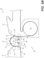
- FIG. 1 shows an example of a CWP papermaking machine 100.
- Papermaking machine 100 has a forming section 110, which, in this case, is referred to in the art as a crescent former.
- the forming section 110 includes headbox 112 that deposits an aqueous furnish between a forming fabric 114 and a papermaking felt 116, thereby initially forming a nascent web 102.
- the forming fabric 114 is supported by rolls 122, 124, 126, 128.
- the papermaking felt 116 is supported by a forming roll 120.
- the nascent web 102 is transferred by the papermaking felt 116 along a felt ran 118 that extends to a press roll 132 where the nascent web 102 is deposited onto a Yankee dryer section 140 in a press nip 130.
- the nascent web 102 is wet-pressed in the press nip 130 concurrently with the transfer to the Yankee dryer section 140.
- the consistency of the web 102 is increased from about twenty percent solids just prior to the press nip 130 to between about thirty percent solids and about fifty percent solids just after the press nip 130.
- the Yankee dryer section 140 comprises, for example, a steam filled drum 142 ("Yankee drum”) and hot air dryer hoods 144, 146 to further dry the web 102.
- the web 102 may be removed from the Yankee drum 142 by a doctor blade 152 where it is then wound on a reel (not shown) to form a parent roll 190.
- a CWP papermaking machine such as papermaking machine 100, typically has low drying costs, and can quickly produce the parent roll 190 at speeds from about three thousand feet per minute to in excess of five thousand feet per minute.
- Papermaking using CWP is a mature process that provides a papermaking machine having high runability and uptime.
- the resulting paper product typically has a low bulk with a corresponding high fiber cost. While this can result in rolled paper products, such as paper towels or toilet paper, having a high sheet count per roll, the paper products generally have a low absorbency and can feel rough to the touch.
- FIG. 2 shows an example of a TAD papermaking machine 200.
- the forming section 230 of this papermaking machine 200 is shown with what is known in the art as a twin-wire forming section and it produces a sheet similar to the crescent former 110 of Figure I.
- the furnish is initially supplied in the papermaking machine 200 through a headbox 202.
- the furnish is directed by the headbox 202 into a nip formed between a first forming fabric 204 and a second forming fabric 206, ahead of forming roll 208.
- the first forming fabric 204 and the second forming fabric 206 move in continuous loops and diverge after passing beyond forming roll 208.
- Vacuum elements such as vacuum boxes, or foil elements (not shown) can be employed in the divergent zone to both dewater the sheet and to insure that the sheet stays adhered to second forming fabric 206.
- the second forming fabric 206 and web 102 pass through an additional dewatering zone 212 in which suction boxes 214 remove moisture from the web 102 and second forming fabric 206, thereby increasing the consistency of the web 102 from, for example, about ten percent solids to about twenty-eight percent solids.
- Hot air may also be used in dewatering zone 212 to improve dewatering.
- the web 102 is then transferred to a through-air drying (TAD) fabric 216 at transfer nip 218, where a shoe 220 presses the TAD fabric 216 against the second forming fabric 206.
- TAD through-air drying
- the shoe 220 is a vacuum shoe that applies a vacuum to assist in the transfer of the web 102 to the TAD fabric 216.
- rush transfer maybe used to transfer the web 102 in transfer nip 218 as well as structure it. Rush transfer occurs when the second forming fabric 206 travels at a speed that is faster than the TAD fabric 216.
- the TAD fabric 216 carrying the paper web 102 next passes around through-air dryers 222, 224 where hot air is forced through the web to increase the consistency of the paper web 102, from about twenty-eight percent solids to about eighty percent solids.
- the web 102 is then 10 transferred to the Yankee dryer section 140, where the web 102 is further dried.
- the sheet is then doctored off the Yankee drum 142 by doctor blade 152 and is taken up by a reel (not shown) to form a parent roll (not shown).
- the resulting paper product has a high bulk with corresponding low fiber cost.
- this process is costly to operate because a lot of water is removed by 15 expensive thermal drying.
- the papermaking fibers in a paper product made by TAD typically are not strongly bound, resulting in a paper product that can be weak.
- FIG 3 shows an example of a papermaking machine 300 used for belt creping. Similar to 25 the CWP papermaking machine 100, shown in Figure I, the belt creping papermaking machine 300 uses a crescent former, discussed above, as the forming section 110. After leaving the forming section 110, the felt run 118, which is supported on one end by roll 108, extends to a shoe press section 310. Here, the web 102 is transferred from the papermaking felt 116 to a backing roll 312 in a nip formed between the backing roll 312 and a shoe press 30 roll 314. A shoe 316 is used to load the nip and dewater the web 102 concurrently with the transfer.
- a crescent former discussed above
- the web 102 is then transferred onto a creping belt 322 in a belt creping nip 320 by the action of the creping nip 320.
- the creping nip 320 is defined between the backing roll 312 and the creping belt 322, with the creping belt 322 being pressed against the backing roll 312 by a creping roll 326.
- the cellulosic fibers of the web 102 are repositioned and oriented.
- the web 102 may tend to stick to the smoother surface of the backing roll 312 relative to the creping belt 322. Consequently, it may be desirable to apply release oils on the backing roll 312 to facilitate the transfer from the backing roll 312 to the creping belt 322.
- the backing roll 312 may be a steam heated roll.
- a vacuum box 324 may be used to apply a vacuum to the web 102 in order to increase sheet caliper by pulling the web 102 into the creping belt 322 topography.
- the web 102 is deposited on a Yankee drum 142 in the Yankee dryer section 140 in a low intensity press nip 328. As with the CWP papermaking machine 100 shown in Figure I, the web 102 is then dried in the Yankee dryer section 140 and then wound on a reel (not shown). While the creping belt 322 imparts desirable bulk and structure to the web 102, the creping belt 322 may be difficult to use. As the creping belt 322 moves through its travel, the belt bends and flexes, resulting in fatigue of the creping belt 322. Thus, the creping belt 322 is susceptible to fatigue failure. In addition, creping belts 322 are custom designed elements with no other commercial analog.
- my invention relates to a method of making a fibrous sheet.
- the method includes forming a nascent web from an aqueous solution of papermaking fibers, dewatering the nascent web to form a dewatered web having a consistency from about ten percent solids to about seventy percent solids, moving the dewatered web on a transfer surface, and transferring the dewatered web from the transfer surface to a molding roll at a molding zone.
- the molding roll includes an exterior and a patterned surface on the exterior of the molding roll. Papermaking fibers of the dewatered web are redistributed on the patterned surface in order to form a molded paper web.
- the method also includes transferring the molded paper web to a drying section and drying the molded paper web in the drying section to form a fibrous sheet.
- my invention relates to a method of making a fibrous sheet.
- the method includes forming a nascent web from an aqueous solution of papermaking fibers, dewatering the nascent web to form a dewatered web having a consistency from about fifteen percent solids to about seventy percent solids, moving the dewatered web on a transfer surface, and transferring the dewatered web from the transfer surface to a first molding roll at a first molding zone.
- the first molding roll includes an exterior and a patterned surface on the exterior of the first molding roll.
- Papermaking fibers of the dewatered web are redistributed on the patterned surface of the first molding roll and a first side of the dewatered web is patterned by the patterned surface of the first molding roll, in order to form a paper web having a molded first side.
- the method further includes transferring the paper web from the first molding roll to a second molding roll at a second molding zone.
- the second molding roll includes an exterior and a patterned surface formed on the exterior of the second molding roll.
- Papermaking fibers of the paper web are redistributed on the patterned surface of the second molding roll and a second side of the paper web is patterned by the patterned surface of the second molding roll, in order to form a molded paper web having molded first and second sides.
- the method includes transferring the molded paper web to a drying section and drying the molded paper web in the drying section to form a fibrous sheet.
- My invention relates to papermaking processes and apparatuses that use a molding roll to produce a paper product.
- I will describe arrangements in detail below with reference to the accompanying figures.
- the same reference numerals will be used to refer to the same or similar components or features.
- the arrangements shown in Figures 4 to 8 and 10 to 18 are embodiments of the present invention. While the arrangement shown in Figure 9 is helpful for understanding the present invention.
- paper product encompasses any product incorporating papermaking fibers. This would include, for example, products marketed as paper towels, toilet paper, facial tissues, etc.
- Papermaking fibers include virgin pulps or recycle (secondary) cellulosic fibers, or fiber mixes comprising at least fifty-one percent cellulosic fibers. Such cellulosic fibers may include both wood and non-wood fibers.
- Wood fibers include, for example, those obtained from deciduous and coniferous trees, including softwood fibers, such as northern and southern softwood kraft fibers, and hardwood fibers, such as eucalyptus, maple, birch, aspen, or the like.
- fibers suitable for making the products of my invention include nonwood fibers, such as cotton fibers or cotton derivatives, abaca, kenaf, sabai grass, flax, esparto grass, straw, jute hemp, bagasse, milkweed floss fibers, and pineapple leaf fibers.
- Additional papermaking fibers could include non-cellulosic substances such as calcium carbonite, titanium dioxide inorganic fillers, and the like, as well as typical manmade fibers like polyester, polypropylene, and the like, which may be added intentionally to the furnish or may be incorporated when using recycled paper in the furnish.
- “Furnishes” and like terminology refers to aqueous compositions including papermaking fibers, and, optionally, wet strength resins, debonders, and the like, for making paper products.
- a variety of furnishes can be used in arrangements. In some arrangements, furnishes are used according to the specifications described in U.S. Patent No. 8,080,130 (the disclosure of which is incorporated by reference in its entirety).
- the initial fiber and liquid mixture (or furnish) that is dried to a finished product in a papermaking process will be referred to as a "web,” “paper web,” a “cellulosic sheet,” and/or a “fibrous sheet.”
- the finished product may also be referred to as a cellulosic sheet and or a fibrous sheet.
- other modifiers may variously be used to describe the web at a particular point in the papermaking machine or process.
- the web may also be referred to as a "nascent web,” a “moist nascent web,” a "molded web,” and a "dried web.”
- machine direction (MD) and “cross machine direction” (CD) will be used in accordance with their well understood meaning in the art. That is, the MD of a fabric or other structure refers to the direction that the structure moves on a papermaking machine in a papermaking process, while CD refers to a direction crossing the MD of the structure. Similarly, when referencing paper products, the MD of the paper product refers to the direction on the product that the product moved on the papermaking machine in the papermaking process, and the CD of the product refers to the direction crossing the MD of the product.
- FIG 4 shows a papermaking machine 400 used to create a paper web according to a first preferred arrangement.
- the forming section 110 of the papermaking machine 400 shown in Figure 4 is a crescent former similar to the forming section 110 discussed above and shown in Figures 1 and 3 .
- An example of an alternative to the crescent forming section 110 includes a twin-wire forming section 230, shown in Figure 2 .
- downstream of the twin-wire forming section the rest of the components of such a papermaking machine may be configured and arranged in a similar manner to that of papermaking machine 400.
- An example of a papermaking machine with a twin-wire forming section can be seen in, for example, U.S. Patent Application Pub. No.
- the nascent web 102 is then transferred along a felt run 118 to a dewatering section 410.
- a dewatering section separate from the forming section 110 is not required, as will be discussed, for example, in the second arrangement below.
- the dewatering section 410 increases the solids content of the nascent web 102 to form a moist nascent web 102.
- the preferable consistency of the moist nascent web 102 may vary depending upon the desired application.
- the nascent web 102 is dewatered to form a moist nascent web 102 having a consistency preferably between about twenty percent solids and about seventy percent solids, more preferably between about thirty percent solids to about sixty percent solids, and even more preferably between about forty percent solids to about fifty-five percent solids.
- the nascent web 102 is dewatered concurrently with being transferred from the papermaking felt 116 to a backing roll 312.
- the dewatering section 410 shown uses a shoe press roll 314 to dewater the nascent web 102 against the backing roll 312, as described above with reference to Figure 3 and in, for example, U.S. Patent No. 6,248,210 .
- the nascent web 102 may be dewatered using any suitable method known in the art including, for example, a roll press or a displacement press as described in my earlier patents, U.S. Patent No. 6,161,303 and No. 6,416,631 .
- the nascent web 102 may also be dewatered using suction boxes and/or thermal drying.
- the surface of the backing roll 312 may be heated to assist with transferring the nascent web 102 to the molding roll 420.
- the backing roll 312 may be heated by using any suitable means including, for example, a steam heated roll or an induction heated roll, such as the induction heated roll produced by Comaintel of Grand-Mère, Québec, Canada.
- the surface of the backing roll 312 is preferably heated to temperatures between about 100°C to 104°C (two hundred twelve degrees Fahrenheit to about two hundred twenty degrees Fahrenheit).
- the moist nascent web 102 is transferred from the surface of the backing roll 312 to a molding roll 420 in a molding zone.
- the molding zone is a molding nip 430 formed between the backing roll 312 and the molding roll 420.
- the papermaking fibers are redistributed by a patterned surface 422 of the molding roll 420 resulting in a paper web 102 that has variable and patterned fiber 10 orientations and variable and patterned basis weights.
- the patterned surface 422 preferably includes a plurality of recesses (or "pockets") and, in some cases, projections that produce corresponding protrusions and recesses in the molded web 102.
- the molding roll 420 is rotating in a molding roll direction, which is counterclockwise in Figure 4 .
- the use of the molding roll 420 imparts substantial benefits to the papermaking process. Wet 15 molding the web 102 with the molding roll 420 improves desirable sheet properties such as bulk and absorbency over paper products produced by CWP shown in Figure I without the inefficiencies and cost of the TAD process shown in Figure 2 .
- the use of the molding roll 420 greatly reduces the complexity of the papermaking machine 400 and process as compared to processes that use belts to mold the web 102, such as creping belt 322 shown in Figure 3 .
- Belts are difficult to manufacture and are limited in the materials that can be used to make a belt with a patterned surface. Belts require the use of multiple rolls and many different moving parts, which make belt runs complex, difficult to operate, and introduce a greater number of points of failure.
- Belt runs also require a large amount of volume including floor space within the paper machine and factory. As a result, such belt runs can increase the costs of an already expensive piece of capital equipment.
- the molding roll 420 on the other hand is relatively less complex and requires minimal volume and floor space.
- Existing CWP machines can be readily converted to a wet molding papermaking process by the addition of a molding roll 420 and a backing roll 312. Because the patterned surface 422 is on or part of the molding roll 420, it does not need to be designed to withstand bending and flexing that are required for belts.
- the moist nascent web 102 may be transferred from the backing roll 312 to the molding roll 420 by a rush transfer.
- the molding roll 420 is traveling at a slower speed than the web 102 and the backing roll 312.
- the web 102 is creped by the speed differential and the degree of creping is often referred to as the creping ratio.
- the web 102 is creped at a ratio of about five percent to about sixty percent.
- the velocity of the paper web 102 on the backing roll 312 may preferably be from about one thousand feet per minute to about six thousand five hundred feet per minute. More preferably velocity of the paper web 102 on the backing roll 312 is as fast as the process allows, which is typically limited by the drying section 440. For higher bulk product where a slower paper machine speeds can be accommodated, a higher creping ratio is used.
- the molding nip 430 may also be loaded in order to effect sheet transfer and to control sheet 20 properties. When rush transfer or other methods, such as vacuum transfer discussed in the third arrangement below, are used, it is possible to have little or no compression at the molding nip 430.
- the backing roll 312 preferably applies a load to the molding roll 420 from about twenty pounds per linear inch ("PLI") to about three hundred PLI, more preferably from about forty PLI to about one hundred fifty PLI. But, for high strength, lower bulk sheets, those skilled in the art will appreciate that, in a commercial machine, the maximum pressure may be as high as possible, limited only by the particular machinery employed.
- PLI pounds per linear inch
- pressures in excess of one hundred fifty PLI, five hundred PLI, or more may be used, if practical, and, when a rush transfer is used, provided the difference in speed between the backing roll 312 and the molding roll 420 can be maintained and sheet property requirements are met.
- the drying section 440 may principally comprise a Yankee dryer section 140.
- the Yankee dryer section 140 includes, for example, a steam filled drum 142 ("Yankee drum") that is used to dry the web 102.
- hot air from wet end hood 144 and dry end hood 146 is directed against the web 102 to further dry the web 102 as it is conveyed on the Yankee drum 142.
- the web 102 is transferred from the molding roll 420 to the Yankee drum 142 at a transfer nip 450.
- the papermaking machine 400 of this arrangement is shown with a direct transfer from the molding roll 420 to the drying section 440, other intervening processes may be placed between the molding roll 420 and drying section 440 without deviating from the scope of my invention.
- transfer nip 450 is also a pressure nip.
- a load is generated between the Yankee drum 142 and the molding roll 420 preferably having a line loading of from about fifty PLI to about three hundred fifty PLI.
- the web 102 will then transfer from the surface of the molding roll 420 to the surface of the Yankee drum.
- an adhesive may be applied to the surface of the Yankee drum 142.
- the adhesive can allow for high velocity operation of the system and high jet velocity impingement air drying, and also allow for subsequent peeling of the web 102 from the Yankee drum 142.
- An example of such an adhesive is a poly(vinyl alcohol)/polyamide adhesive composition, with an example application rate of this adhesive being at a rate of less than about forty milligrams per meter squared of sheet.
- the web 102 is removed from the Yankee drum 142 with the help of a doctor blade 152. After being removed from the Yankee dryer section 140, is taken up by a reel (not shown) to form a parent roll 190.
- a reel not shown
- operations may include, for example, calendering and drawing.
- the patterned surface 422 of the molding roll 420 may require cleaning. Papermaking fibers and other substances may be retained on the patterned surface 422 and, in 5 particular, the pockets. At any one time during operation, only a portion of the patterned surface 422 is contacting and molding the paper web 102. In the arrangement of rolls shown in Figure 4 , about half of the circumference of the molding roll 420 is contacting the paper web 102 and the other half (hereafter free surface) is not. A cleaning section 460 may then be positioned opposite to the free surface of the molding roll 420 to clean the patterned 10 surface 422. Any suitable cleaning method and device known in the art may be used.
- the cleaning section 460 depicted in Figure 4 is a needle jet such as JN Spray Nozzles made by Kadant of Westford, MA.
- a nozzle 462 is used to direct a cleaning medium, such as a high pressure stream of water and/or a cleaning solution, toward the patterned surface 422 in a direction that opposes the rotating direction of the molding roll 420.
- the angle the cleaning medium flows is preferably between a line tangent to the patterned surface 422 at the point the cleaning medium strikes the patterned surface 422 and perpendicular to the patterned surface 422 at the same point.
- the cleaning medium then chisels and removes any particulate matter that has built-up on the patterned surface 422.
- the nozzle 462 and stream are located in an enclosure 464 to collect the cleaning medium and particulate matter.
- Enclosure 464 may be under vacuum to assist in collecting the cleaning medium and particulate matter.
- Figure 5 shows a second preferred arrangement. It has been found that the lower the consistency of the moist nascent web 102 is when it is molded on the molding roll 420, the greater affect molding has on desirable sheet properties such as bulk and absorbency. Thus in general, it is advantageous to minimally dewater the nascent web 102 to increase sheet bulk and absorbency, and in some cases, the dewatering that occurs during forming may be sufficient for molding.
- the moist nascent web 102 preferably has a consistency between about ten percent solids to about thirty-five percent solids, more preferably between about fifteen percent solids to about thirty percent solids.
- the moist nascent web 102 may thus be molded over a range of consistencies extending from about ten 5 percent solids to about seventy percent solids.
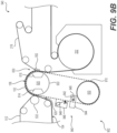
- FIG. 5 An example papermaking machine 500 of the second arrangement using a TAD drying section 540 is shown in Figure 5 .
- any suitable forming section 510 may be used to form and dewater the web 102, in this arrangement, the twin wire forming section 510 is similar to that discussed above with respect to Figure 2 .
- the web 102 is then transferred from the second forming fabric 206 to a transfer fabric 512 at transfer nip 514, where a shoe 516 presses the transfer fabric 512 against the second forming fabric 206.
- the shoe 516 may be a vacuum shoe that applies a vacuum to assist in the transfer of the web 102 to the transfer fabric 512.
- the wet web 102 then encounters a molding zone.
- the molding zone is a molding nip 530 formed by roll 532, the transfer fabric 512, and the molding roll 520.
- molding roll 520 and molding nip 530 are constructed and operated similarly to the molding roll 420 and molding nip 430 discussed above with reference to Figure 4 .
- the web 102 may be rush transferred from the transfer fabric 512 to the molding roll 520 as discussed above and roll 532 maybe loaded into the molding roll 520 to control sheet transfer and sheet properties.
- the molding roll 520 has a permeable patterned surface 522, which is similar to the patterned surface 422 of the molding roll 420, preferably having a plurality of recesses (or "pockets”) and, in some cases, projections that produce corresponding protrusions and recesses in the molded web 102.
- the nascent web 102 may be minimally dewatered with a separate vacuum dewatering zone 212 in which suction boxes 214 remove moisture from the web 102 to achieve desirable consistencies of about ten percent solids and about thirty-five percent solids before the sheet reaches molding nip 530.
- Hot air may also be used in dewatering zone 212 to improve dewatering.
- the web 102 is then transferred from the molding roll 520 to a drying section 540 at a transfer nip 550.
- a vacuum may be applied to assist in the transfer of the web 102 from the molding roll 520 to the through-air drying fabric 216 using a vacuum shoe 552 in the transfer nip 550. This transfer may occur with or without a speed difference between molding roll 520 and TAD fabric 216.
- the total creping ratio (calculated by adding the creping ratios in each nip) is preferably between about five percent to about sixty percent. But as with molding nip 430 (see Figure 4 ), high degrees of crepe can be employed, approaching or even exceeding one hundred percent.
- the TAD fabric 216 carrying the paper web 102 next passes around through-air dryers 222, 224 where hot air is forced through the web to increase the consistency of the paper web 102, to about eighty percent solids.
- the web 102 is then transferred to the Yankee dryer section 140, where the web 102 is further dried and, after being removed from the Yankee dryer 20 section 140 by doctor blade 152, is taken up by a reel (not shown) to form a parent roll (not shown).
- this configuration gives a means to control so-called sidedness of the sheet.
- Sidedness can occur when one side of the paper web 102 has (or is perceived to have) different properties on one side of the paper web 102 and not the other.
- the Yankee side of the paper web 102 may be perceived to be softer than the air side because, as the paper web 102 is pulled from the Yankee drum 142 by the doctor blade 152, the doctor blade 152 crepes the sheet more on the Yankee side of the sheet than on the air side of the sheet.
- the side contacting the molding surface may have an increased roughness (e.g., deeper recesses and higher protrusions) as compared to the non-molded side.
- the side of a molded paper web 102 contacting the Yankee drum 142 may be further smoothed when it is applied the Yankee drum 142.
- the molded structure imparted to the paper web 102 may not continue 10 through the full thickness of the paper web 102.
- Transfer of the wet web 102 in molding nip 530 thus predominately molds a first side 104 of the paper web 102, and transfer in the transfer nip 550 predominately molds a second side 106 of the paper web 102.
- Individually controlling the nip parameters at both the molding nip 530 and the transfer nip 550 can counteract sidedness.
- the patterned surface 522 of the molding roll 520 may be designed with pockets and projections that impart recesses and protrusions that are deeper and higher, respectively, on the first side 104 of the paper web 102 (prior to the paper web 102 being applied to the Yankee drum 142) than are imparted by the TAD fabric 216 to the second side 106 of the paper web 102.
- both the first and second sides 104, 106 of the paper web 102 have substantially the same properties.
- a user may perceive that both sides have the same roughness and softness, or commonly measured paper properties are within normal control tolerances for the paper product.
- Counteracting sidedness is not limited to adjusting the patterned structure of the molding roll 520 and the TAD fabric 216. Sidedness can also be counteracted by controlling other nip parameters including the creping ratio and/or the loading of each nip 530, 550.
- Figures 6A and 6B show a third preferred arrangement.
- the papermaking machine 600 of the third arrangement may have the same forming section 110, dewatering section 410, and drying section 440 as the papermaking machine 400 of the first arrangement shown in Figure 4 .
- the papermaking machine 602 of the third arrangement may have the same forming section 510 and drying section 540 of the second arrangement shown in Figure 5 .
- the descriptions of those sections are omitted here.
- the molding roll 610 of the third arrangement has a patterned surface 612 preferably having a plurality of recesses ("pockets").
- the molding roll 610 of the third arrangement uses a pressure differential to aid the transfer of the web 102 from the backing roll 312 or transfer fabric 512 to the molding roll 610.
- the molding roll 610 has a vacuum section 10 ("vacuum box") 614 located opposite to the backing roll 312 in Figure 6A or roll 532 in
- FIG 6B in a molding zone.
- the molding zone is molding nip 620.
- the patterned surface 612 is permeable such that a vacuum box 614 can be used to establish a vacuum in the molding nip 620 by drawing a fluid through the permeable patterned surface 612.
- the vacuum in the molding nip 620 draws the paper web 102 onto the permeable patterned surface 612 of the molding roll 610 and, in particular, into the plurality of pockets in the permeable patterned surface 612.
- the vacuum thus molds the paper web 102 and reorients the papermaking fibers in the paper web 102 to have variable and patterned fiber orientations.
- a vacuum is applied subsequent to the transfer to the creping belt 322 by vacuum box 324.
- a vacuum is applied as the paper web 102 is transferred.
- both the mobility of the fibers during transfer and the pull of the vacuum increases the depth of fiber penetration into the pockets of the permeable patterned surface 612.
- the increased fiber penetration results in an improved sheet molding 25 amplitude and a greater impact of wet molding on resultant web properties, such as improved bulk.
- Vacuum transfer allows the molding nip 620 to utilize reduced or no nip loading. Vacuum transfer may thus be a less-compactive or even a non-compactive process. Compaction may be reduced or avoided between the projections of patterned surface 612 and the papermaking fibers located in the corresponding recesses formed in the web 102. As a result, the paper web 102 may have a higher bulk than one made from a compactive process, such as fabric creping (shown in Figure 3 ) or CWP (shown in Figure I).
- fabric creping shown in Figure 3
- CWP shown in Figure I
- Reducing the loading at, or not loading, the molding nip 620 can also reduce the amount of wear between the backing roll 312 or transfer fabric 512 and the molding roll 610, as compared to wear between the backing roll 312 and the creping belt 322 shown in Figure 3 . Reducing wear is especially important for nips that employ rush transfer because increasing crepe ratios (%) and/or increasing crepe roll loadings tend to increase wear and thus can lead to reduced runtimes.
- release agents can be 10 reduced or even eliminated.
- the paper web 102 tends to stick to the smoother of two surfaces during a transfer.
- release agents are preferably used in fabric creping to assist in the transfer of the paper web 102 from the backing roll 312 to the creping belt 322 (see Figure 3 ).
- Release agents require careful formulation in order to work. They also can build up on the backing roll 312 or can be retained in the paper web 102.
- the use of release agents adds complexity to the papermaking process, reduces the runability of the paper machine when they are not effective, and may be deleterious to the paper web 102 properties. In this arrangement, all of these issues can thus be avoided by using vacuum at the point of transfer from the backing roll 312 or transfer fabric 512 to the molding roll 610.
- the vacuum level in the molding nip 620 is suitably large enough to draw the paper web 102 from the backing roll 312 or transfer fabric 512.
- the vacuum is from about zero inches of mercury to about twenty-five inches of mercury, and more preferably from about ten inches of mercury to about twenty-five inches of mercury.
- the MD length of the vacuum zone of the molding roll 610 is large enough to draw the paper web 102 from the backing roll 312 or transfer fabric 512 and into the molding surface 612. Such MD lengths may be as small as about two inches or less. The preferable lengths may depend on the rotational speed of the molding roll 610.
- the web 102 is preferably subject to vacuum for a sufficient amount of time to draw the papermaking fibers into the pockets.
- the MD length of the vacuum zone is preferably increased as the rotational speed of the molding roll 610 is increased.
- the upper limit of MD length of the vacuum box 614 is driven by the desire to reduce energy consumption and maximize the area within the molding roll 610 for other components such as a cleaning section 640.
- the MD length of the vacuum zone is from about a quarter of an inch to about five inches, more preferably from about a quarter of an inch to about two inches.
- the vacuum zone is not limited to a single vacuum zone, but a multi-zone vacuum box 614 may be used.
- a multi-zone vacuum box 614 may be used.
- the first stage exerts a high level vacuum to draw the paper web 102 from the backing roll 312 or transfer fabric 512 and the second stage exerts a lower level vacuum to mold the paper web 102 by drawing it against the permeable patterned surface 612 and the pockets therein.
- the MD length and vacuum level of the first stage is preferably just large enough to effect transfer of the paper web 102.
- the MD length of the first stage is preferably from about a quarter of an inch to about five inches, more preferably from about a half of an inch to about two inches.
- the vacuum is preferably from about zero inches of mercury to about twenty-five inches of mercury, and more preferably from about ten inches of mercury to about twenty inches of mercury.
- the MD length of the second stage is preferably larger than the first. Because vacuum is applied to the paper web 102 over a longer distance, the vacuum can be reduced resulting in a paper web 102 having higher bulk.
- the MD length of the second stage is preferably from about a quarter of an inch to about five inches, more preferably from about 25 a half of an inch to about two inches.
- the vacuum is preferably from about ten inches of mercury to about twenty-five inches of mercury, and more preferably from about fifteen inches of mercury to about twenty-five inches of mercury.
- the moist nascent web 102 may be advantageously dewatered.
- the vacuum draws out water from the moist nascent web 102, as the web 102 30 travels on the permeable patterned surface 612 through the vacuum zone (vacuum box 614).
- the degree of dewatering is a function of several considerations including the dwell time of the moist nascent web 102 in the vacuum zone, the strength of the vacuum, the crepe nip load, the temperature of the web, and the initial consistency of the moist nascent web 102.
- the molding nip 620 is not limited to this design. Instead, for example, features of the molding nip 430 of the first arrangement or molding nip 530 of the second arrangement may be incorporated with the molding roll 610 of the third arrangement. For example, it may be desirable to even further increase the bulk of the paper web 102 by combining the molding roll 610 having the vacuum box 614 with a rush transfer, which further crepes the web 102, and the vacuum molds it at the same time.
- the molding roll 610 of the third arrangement may also have a blow box 616 at transfer nip 630 where the web 102 is transferred from the permeable patterned surface 612 of the molding roll 610 to the surface of the Yankee drum 142 or TAD fabric 216.
- blow box 616 provides several benefits in transfer nip 630, the web may be transferred to the drying section 440, 540 without it, as discussed above with reference to transfer nip 450 (see Figure 4 ) or transfer nip 550 of (see Figure 5 ).
- the drying section is a TAD drying section (see Figure 6B )
- the web 102 may be transferred in the transfer nip 550 using the blow box 616, the vacuum shoe 552, or both.
- Positive air pressure may be exerted from the blow box 616 through the permeable patterned surface 612 of the molding roll 610.
- the positive air pressure facilitates the transfer of the molded web 102 at transfer nip 630 by pushing the web away from the permeable patterned surface 612 of the molding roll 610 and towards the surface of the Yankee drum 142 (or TAD fabric 216).
- the pressure in the blow box 616 is set at a level consistent with good transfer of the sheet to the drying section 440, 540 and is dependent on box size, and roll construction. There should be enough pressure drop across the sheet to cause it to release from the patterned surface 612.
- the MD length of the blow box 616 is preferably from about a quarter of an inch to about five inches, more preferably from about a half of an inch to about two inches.
- the contact pressure between the molding roll 610 and the Yankee drum 142 or TAD fabric 216 may be reduced or even eliminated, thus resulting in less compaction of the web 102 at contact points, thus higher bulk.
- the air pressure from the blow box 616 urges the fibers at the permeable patterned surface 612 to transfer with the rest of the web 102 to the Yankee drum 142 or TAD fabric 216, thus reducing fiber picking. Fiber picking may cause small holes (pin holes) in the web 102.
- blow box 616 Another advantage of the blow box 616 is that it assists in maintaining and cleaning the patterned surface 612.
- the positive air pressure through the roll can help to prevent the accumulation of fibers and other particulate matter on the roll.
- a cleaning section 640 may be constructed opposite to the free surface of the molding roll 610 (e.g., cleaning section 460 as shown in Figure 4 ). Any suitable cleaning method and device known in the art may be used, including the needle jet discussed above.
- a cleaning section may be constructed inside the molding roll 610 in the section of the molding roll 610 having the free surface.
- An advantage of the permeable patterned surface 612 is that cleaning devices may be placed on the interior of the molding roll to clean by directing a cleaning solution or cleaning medium outward.
- Such a cleaning device may include a blow box (not shown) or an air knife (not shown) that forces pressurized air (as the cleaning medium) though the permeable patterned surface 612.
- Another suitable cleaning device may be showers 642, 644 located in the molding roll 610.
- the showers 642, 644 may spray water and/or a cleaning solution outward through the permeable patterned surface 612.
- vacuum boxes 646, 648 are positioned opposite to each shower 642, 644 on the exterior to collect the water and/or cleaning solution.
- a receptacle 649 which may be a vacuum box, encloses the showers 642, 644 to collect any water and/or cleaning solution that remains in the interior of the molding roll 610.
- FIGs 7A and 7B show a fourth arrangement.
- molding may be improved by increasing the mobility of the papermaking fibers in the molding zone, which is a molding nip 710 in this arrangement.
- the papermaking machines 700, 702 of the fourth arrangement are similar to the papermaking machines 600, 602 (see Figures 6A and 6B , respectively) of the third arrangement, but includes features to heat the moist nascent web 102.
- the vacuum box 720 is a dual zone vacuum box, having a first vacuum zone 722 and a second vacuum zone 724.
- the first vacuum zone 722 is positioned opposite to the backing roll 312 or roll 532 and is used to transfer the moist nascent web 102 from the backing roll 312 or transfer fabric 512 to the molding roll 610.
- the first vacuum zone 722 is preferably shorter and uses a greater vacuum than the second vacuum zone 724.
- the first vacuum zone 722 is preferably less than about two inches and preferably draws a vacuum between about two inches of mercury and about twenty-five inches of mercury.
- the nascent web 102 is heated on the molding roll 610 using a steam shower 730.
- Any suitable steam shower 730 may be used with my invention including, for example, a Lazy Steam injector manufactured by Wells Enterprises of Seattle Washington.
- the steam shower 730 is positioned proximate to the molding nip 710 and opposite to the second vacuum zone 724 of the vacuum box 720.
- the steam shower 730 generates steam (for example saturated or superheated steam).
- the steam shower 730 directs the steam toward the moist nascent web 102 on the patterned surface 612 of the molding roll 610 and the second vacuum zone 724 of the vacuum box 720 uses a vacuum to draw the steam though the web 102, thus, heating the web 102 and the papermaking fibers therein.
- the second vacuum zone 724 is preferably from about two inches to about twenty-eight inches and preferably draws a vacuum between about five inches of mercury and about twenty-five inches of mercury.
- the steam shower 730 may be suitably used without a vacuum zone.
- the temperature of the steam is preferably from about two hundred twelve degrees Fahrenheit to about two hundred twenty degrees Fahrenheit. Any suitable heated fluid may be emitted by the steam shower, including, for example, heated air or other gas.
- Heating the moist nascent web 102 in the molding nip 710 is not limited to a heated fluid emitted from a steam shower 730. Instead, other techniques to heat the moist nascent web 102 may be used including, for example, heated air, a heated backing roll 312, or heating the molding roll 420, 520, 610 itself.
- the molding roll 420, 520, 610, and in particular the molding roll 420, 520 of the first and second arrangements may be heated like the backing roll 312 by using any suitable means including, for example, steam or induction heating.
- the moist nascent web 102 may be heated and dried while being molded on the molding rolls 420, 520 of the first and second arrangements.
- FIG 8 shows a fifth arrangement.
- the papermaking machine 800 of the 5 fifth arrangement is similar to the papermaking machine 600 (see Figure 6A ) of the third arrangement, but includes a doctor blade 810 at the molding zone 820.
- the doctor blade 810 is used to peel the web from the backing roll 312 and to facilitate transfer of the web 102 to the molding roll 610.
- the sheet is removed from the backing roll 312, by the doctor blade 810, it introduces crepe to the web, which is known to increase sheet caliper and bulk.
- implementation of this arrangement provides the ability to add additional bulk to the overall process.
- doctor blade 810 removes the need for contact between the backing roll 312 and the molding roll 610 because the vacuum box 614 in the molding roll 610 will effect sheet transfer to the patterned surface 612 without roll contact.
- roll wear is 15 reduced, especially when there are speed differences between the rolls.
- the doctor blade 810 may oscillate to further crepe the web 102 at the molding zone 820. Any suitable doctor blade 810 may be used with my invention, including, for example, the doctor blade disclosed in U.S. Patent No. 6,113,470 .
- FIGS 9A and 9B show a sixth arrangement.
- the papermaking machines 900, 902 of the sixth arrangement are similar to the papermaking machines 600, 602 of the third arrangement ( Figures 6A and 6B , respectively).
- a molding fabric 910 is used and the molding fabric 910 is patterned to impart structure to the moist nascent web 102 like the permeable patterned surface 612 discussed in the third, fourth, and fifth arrangements.
- the molding fabric 910 is supported on one end by a molding roll 920 and a support roll 930 on the other end.
- the molding roll 920 has a permeable shell 922 (as will be discussed further below).
- the permeable shell 922 allows a vacuum box 614 and a blow box 616 to be used, as discussed above in the third arrangement.
- this arrangement includes a cleaning section 940.
- the cleaning section 940 5 may be located on the fabric run between the molding roll 920 and the support roll 930. Any suitable cleaning device may be used. Similar to the third arrangement, a shower 942 enclosed in a receptacle 945 may be positioned on an interior of the fabric run to direct water and/or a cleaning solution outward through the molding fabric 910. A vacuum box 944 may be located opposite to the shower 942 to collect the water and/or cleaning solution. Similar to the first and second arrangements, a needle jet may also be used in an enclosure 948 to direct water and/or a cleaning solution at an angle from a nozzle 946. Enclosure 948 maybe under vacuum to collect the solution emitted by the spray nozzle 946.
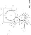
- FIGS 10A and 10B show a seventh arrangement.
- the papermaking machine 1000 shown in Figure 10A is similar to the papermaking machine 400 of the first arrangement.
- the papermaking machine 1002 shown in Figure 10B is similar to the papermaking machine 500 of the second arrangement.
- two molding rolls 1010, 1020 are used instead of one.
- the first molding roll 1010 is used to structure one side (a first side 104) of the paper web 102 using a patterned surface 1012
- the second molding roll 1020 is used to structure the other side (a second side 106) using a patterned surface 1022.
- Molding both surfaces of the web 102 may have several advantages; for example, it may be possible to achieve the benefits of a two-ply paper product with only a single ply, since each side of the sheet can be independently controlled by the two molding rolls 1010, 1020. Also, individually molding each side of the paper web 102 may also help to reduce sidedness. In the papermaking machine 1002 shown in Figure 10B , having two molding rolls 1010, 1020 also enables the wet web 102 to be directly transferred to the first molding roll 1010 from the second forming fabric 206 and the transfer fabric 512 of Figure 5 to be omitted.
- each molding roll 1010, 1020 may not continue through the full thickness of the paper web 102.
- the sheet properties of each side of the paper web 102 may thus be individually controlled by the corresponding molding roll 1010, 1020.
- the patterned surfaces 1012, 1022 of each molding roll 1010, 1020 may have a different construction and/or pattern to impart a different structure to each side of the paper 5 web 102.
- the construction is not so limited, and the molding rolls 1010, 1020, particularly, the patterned surfaces 1012, 1022, may be constructed the same.
- the patterned surface 1012 of the first molding roll 1010 may have deeper pockets and higher projections than the patterned surface 1022 of the second molding roll 1020.
- the first side 104 of the paper web 102 will have recesses and protrusions that are deeper and higher than the second side 106 of the paper web 102 prior to the paper web 102 being applied to the Yankee drum 142.
- both the first and second sides 104, 106 of the paper web 102 have substantially the same properties. For example, a user may perceive that both sides have the same roughness and softness, or commonly measured paper properties are within normal control tolerances for the paper product.
- the paper web 102 is transferred from the backing roll 312 or second forming fabric 206 in a first molding zone, which is a first molding nip 1030 in this arrangement.
- first molding zone which is a first molding nip 1030 in this arrangement.
- the paper web 102 is then transferred from the first molding roll 1010 to the second molding roll 1020 in a second molding zone, which is a second molding nip 1040 in this arrangement.
- the paper web 102 may be transferred in both molding nips 1030, 1040 by, for example, rush transfer.
- the web 102 is creped in each of the two molding nips 1030, 1040 at a ratio of about five percent to about sixty percent.
- the paper web 102 is transferred from the second molding roll 1020 to the drying section 440, 540 in transfer nip 1050.
- the drying section 440 includes a Yankee dryer section 140, and the same considerations that apply to the transfer nip 450 of the first arrangement apply (see Figure 4 ) to the transfer nip 1050 of this arrangement.
- a TAD drying section 540 is used, and the same considerations that 20 apply to the transfer nip 550 (see Figure 5 ) of the second arrangement apply to the transfer nip 1050 of this arrangement.
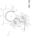
- Figures IIA and I IB show an eighth arrangement.
- the papermaking machines 1100, 1102 of the eighth arrangement are similar to the papermaking machines 1000, 1002 of the seventh arrangement, but the two molding rolls 1110, 1120 of the eighth arrangement are constructed similarly to the molding roll 610 of the third arrangement (see Figures 6A and 6B ) instead of the molding rolls 420, 520 of the first and second arrangements.
- the first molding roll 1110 has a permeable patterned surface 1112 and a vacuum box 1114.
- the moist nascent web 102 is transferred from the backing roll 312 or second forming fabric 206 in a first molding zone, which is a first molding nip 1130 in this arrangement, using any combination of vacuum transfer using the vacuum box 1114 of the first molding roll 1110, rush transfer (see Equation (4)) or a doctor blade 810 (see Figure 8 ).
- the first molding nip 1130 may be operated similarly to the molding nip 620 of the third arrangement.
- the paper web is transferred from the first molding roll 1110 to the second molding roll 1120 in a second molding zone, which is a second molding nip 1140 in this arrangement, using any combination of a vacuum transfer using vacuum box 1124 of the second molding roll 1120, pressure differential using blow box 1116 of the first molding roll 1110, rush transfer (see Equation (5)).
- the second side 106 of the paper web 102 is then molded on the permeable patterned surface 1122 of the second molding roll 1120.
- the types of transfers used individually or in combination can be varied to control sheet properties and sheet sidedness.
- the considerations and parameters that apply to the blow box 616 and vacuum box 614 in the third arrangement also apply to the blow box 1116 of the first molding roll 1110 and the vacuum box 1124 of the second molding roll 1120.
- the paper web 102 is transferred from the second molding roll 1120 to the drying section 440, 540 in transfer nip 1150.
- the drying section 440 includes a Yankee dryer section 140.
- a TAD drying section 540 is used.
- the same considerations that apply to the features of the transfer nip 630 in the third arrangement apply to the transfer nip 1150 of this arrangement, including the use of a blow box 1126 (similar to blow box 616) in the second molding roll 1120.
- Various properties of the resultant fibrous sheet can be measured by techniques known in the art. Some properties may be measured in real time, while the paper web 102 is being processed. For example, moisture content and basis weight of the paper web 102 may be measured by a web property scanner positioned after the Yankee drum 142 and before the parent roll 190. Any suitable web property scanner known in the art may be used, such as an MXProLine scanner manufactured by Honeywell of Morristown, NJ, that is used to measure the moisture content with beta radiation and basis weight with gamma radiation. Other properties, for example, tensile strength (both wet and dry), caliper, and roughness, are more suitably measured offline. Such offline measurements can be conducted by taking a sample of the paper web 102 as it is produced on the paper machine and measuring the property in parallel with production or by taking a sample from the parent roll 190 and measuring the property after the parent roll 190 has been removed from the paper machine.
- process parameters can be adjusted to have an impact on the resulting fibrous sheet.
- process parameters include, for example: the consistency of the moist nascent web 102 at the molding nips 430, 530, 620, 710, 1030, 1040, 1130, 1140 or molding zone 820; creping ratios; the load at the molding nips 430, 530, 620, 710, 1030, 1040, 1130, 1140; the vacuum drawn by vacuum boxes 614, 720, 1114, 1124; and the air pressure generated by blow boxes 616, 1116, 1126.
- a measured value for each paper property of the resultant fibrous sheet lies within a desired range for that paper property.
- the desired range will vary depending upon the end product of the paper web 102. If a measured value for a paper property falls outside the desired range, an operator can adjust the various process parameters of this invention so that, in a subsequent measurement of the paper property, the measured value is within the desired range.
- the vacuum drawn by vacuum boxes 614, 720, 1114, 1124 and the air pressure generated by 20blow boxes 616, 1116, 1126 are process parameters that can be readily and easily adjusted while the paper machine is in operation.
- the papermaking processes of my invention in particular those described in arrangements three through six and eight, may be advantageously used to make consistent fibrous sheet products by real time or near real time adjustment to the papermaking process.
- FIG. 12 is a perspective view of the molding roll 610
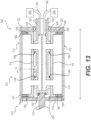
- Figure 13 is a cross-sectional view of the molding roll 610 shown in Figure 12 taken along the plane 13-13.
- the molding roll 610 has a radial direction and a cylindrical shape with a circumferential direction C (see Figure 14 ) that corresponds to the MD direction of the papermaking machine 600.
- the molding roll 610 also has a length direction L (see Figure 13 ) that corresponds to the CD direction of the papermaking machine 600.
- the molding roll 610 may be driven on one end, the driven end 1210. Any suitable method known in the art may be used to drive the driven end 1210 of the molding roll 610.
- the other end of the molding roll 610, the rotary end 1220, is supported by and rotates about a shaft 1230.
- the driven end 1210 includes a driven endplate 1212 and a shaft 1214, which may be driven.
- the rotary end 1220 includes a rotary endplate 1222. In 10 this arrangement, the driven endplate 1212 and the rotary endplate 1222 are constructed from steel, which is a relatively inexpensive structural material.
- endplates 1212, 1222 may be constructed from any suitable structural material.
- the rotary plate 1222 is attached to the shaft 1230 by a bearing 1224.
- a permeable shell 1310 is attached to the circumference of each of the driven endplate 1212 and the rotary 15 endplate 1222 forming a void 1320 there between.
- the permeable patterned surface 612 is formed on the exterior of the permeable shell 1310. The details of the permeable shell 1310 will be discussed further below.
- the vacuum box 614 and the blow box 616 are located in the void 1320 and are supported by shaft 1230 and a rotary connection 1352 to driven endplate 1212 through support structure 1354.
- Support structure 1354 allows both vacuum and pressurized air to be conveyed to vacuum box 614 and blow box 616, respectively, through the shaft 1230.
- Both the vacuum box 614 and the blow box 616 are stationary, and the permeable shell 1310 rotates around the stationary boxes 614, 616.
- Figure 13 shows these boxes to be opposite to each other on the roll, it is recognized that they can be disposed at any angle around the roll circumference as needed to carry out their functions.
- Vacuum is drawn in vacuum box 614 through the use of a vacuum line 1332 that is part of the box support structure 1354.
- a vacuum pump 1334 thus is able to apply a vacuum to the vacuum box 614 via vacuum line 1332.
- a pump or blower 1344 is used to force air through pressure line 1342 to create a positive pressure in blow box 6
- Figure 14 shows cross section of the permeable shell 1310 and vacuum box 614, taken along line 14-14 in Figure 13 .
- the blow box 616 is constructed in substantially the same way as is the vacuum box 614.
- the vacuum box 614 is substantially u-shaped having a first top ends 1420 and a second top end 1430.
- An open portion extends between the two top ends 1420, 1430 having a distance D in the circumferential (MD) direction C of the molding roll 610.
- the distance D of the open portion forms the vacuum zones discussed above.
- the vacuum box 614 is constructed from stainless steel with walls that are thick enough to accommodate the vacuum generated in the cavity 1410 and to withstand the rigors of roll operation.
- the vacuum box 614 is depicted with one single cavity 1410 extending in the length (CD) direction L of the molding roll 610. To draw a uniform vacuum across in the length (CD) direction L, it may be desirable to subdivide the vacuum box 614 into multiple cavities 1410. Those skilled in the art will recognize that any number of cavities may be used. Likewise, it may be desirable to subdivide the vacuum box 614 into multiple cavities in the circumferential (MD) direction C to form, for example, the two stage vacuum box discussed above.
- MD circumferential
- a seal is formed between each end 1420, 1430 of the vacuum box 614 and an inside surface of the permeable shell 1310.
- a tube 1422 is positioned in a cavity formed in the first top end 1420 of the vacuum box 614. Pressure is applied to inflate the 20 tube 1422 and to press a sealing block 1424 against the inside surface of the permeable shell 1310.
- two tubes 1432 are positioned inside cavities formed in the second top end 1430 and used to press a sealing block 1434 against the inside surface of the permeable shell 1310.
- an internal roll shower 1440 may be positioned upstream of the vacuum box to apply a lubricating material, such as water, to the bottom surface of the permeable shell 1310, thereby reducing frictional forces and wear between the sealing blocks 1424, 1434 and the permeable shell 1310.
- a lubricating material such as water
- each end in the CD direction of the vacuum box 614 and blow box 616 are sealed.
- a tube 1362 is positioned in a cavity formed in the ends of the vacuum box 614 and blow box 616 and inflated to press a sealing block 1364 against the inside surface of the permeable shell 1310.
- Any suitable wear material such as polypropylene or a polytetrafluoroethylene impregnated polymer, may be used as the sealing blocks 1364, 1424, and 1434.
- Any suitable inflatable material such a rubber, may be used for the tubes 1362, 1422, 1432.
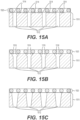
- Figures 15A through 15E are arrangements of the permeable shell 1310 showing detail 15 in Figure 14 .
- Figures 15 A, 15B, and 15C show a two layer construction of the permeable shell 1310. The innermost layer is structural layer 1510, and the outer layer is a molding layer 1520.
- the structural layer 1510 provides the permeable shell 1310 support.
- the structural layer 1510 is made from stainless steel, but any suitable structural material may be used.
- the thickness of the shell is designed to withstand the forces exerted during paper production, including, for example, the forces exerted when the molding nip 620 in the third arrangement is a pressure nip.
- the thickness of the structural layer 1510 is designed to withstand the loads on the roll to avoid fatigue and other failure. For example, the thickness will depend on the length of the roll, the diameter of the roll, the materials used, the density of channels 1512, and the loads applied. Finite element analysis can be used to determine practical roll design parameters and roll crown, if needed.
- the structural layer 1510 has a plurality of channels 1512.
- the plurality of channels 1512 connects the outer layer of the permeable shell 1310 with the inside of the molding roll 610.
- a vacuum is drawn or a pressure is exerted from either of the vacuum box 614 or blow box 616, respectively, the air is pulled or pushed through the plurality of channels 1512.
- the molding layer 1520 is patterned to redistribute and to orient the fibers of the web 102 as discussed above.
- the molding layer 1520 is the permeable patterned surface 612 of the molding roll 610.
- my invention is particularly suited for producing absorbent paper products, such as tissue and towel products.
- the molding layer 1520 is preferably patterned on a fine scale suitable to orient fibers of the web 102.
- the density of each of the pockets and projections of the molding layer 1520 is preferably greater than about fifty per square inch and more preferably greater than about two hundred per square inch.
- Figure 16 is an example of a preferred plastic, woven fabric that may be used as the molding layer 1520.
- the woven fabric is shrunk around the structural layer 1510.
- the fabric is mounted in the apparatus as the molding layer 1520 such that its MD knuckles 1600, 1602, 1604, 1606, 1608, 1610 and so forth extend along the machine direction of the papermaking machine (e.g., 600 in Figure 6A ).
- the fabric may be a multi-layer fabric having creping pockets 1620, 1622, 1624, and so forth, between the MD knuckles of the fabric.
- a plurality of CD knuckles 1630, 1632, 1634, and so forth, is also provided, which may be preferably recessed slightly with respect to the MD knuckles 1600, 1602, 1604, 1606, 1608, 1610 of the creping fabric.
- the CD knuckles 1630, 1632, 1634 may be recessed with respect to the MD knuckles 1600, 1602, 1604, 1606, 1608, 1610 a distance of from about 0.1 mm to about 0.3 mm.
- This geometry creates a unique distribution of fiber when the web 102 is wet molded from the backing roll 312 or transfer fabric 512, as discussed above. Without intending to be bound by theory, it is believed that the structure illustrated, with relatively large recessed "pockets" and limited knuckle length and height in the CD, redistributes the fiber upon high impact creping to produce a sheet, which is especially suitable for recycle furnish and provides surprising caliper.
- the molding layer 1520 is not attached to the structural layer 1510 and is the molding fabric 910 shown in Figures 9A and 9B .
- the molding layer 1520 is not limited, however, to woven structures.
- the molding layer 1520 may be a layer of plastic or metal that has been patterned by knurling, laser drilling, etching, machining, embossing, and the like.
- the layer of plastic or metal may be suitably patterned either before or after it is applied to the structural layer 1510 of molding roll 610.
- the spacing and diameter of the plurality of channels 1512 are preferably designed to provide a relatively uniform vacuum or air pressure at the roll surface of the molding layer 1520.
- grooves 1514 that extend or radiate from the plurality of channels 1512 may be cut in the outer surface of the structural layer 1510.
- other suitable channel designs may be used to assist in spreading the suction or air pressure under the molding layer 1520.
- the top edge of the each channel 1512 may have a chamfer 1516, as shown in Figure 15B .
- the channel 1512 geometry is not limited to right, circular cylinders. Instead, other suitable geometries may be used including, for example, a right, trapezoidal cylinder, as shown in Figure 15C , which may be formed when the plurality of channels 1512 is created by laser drilling.
- the plurality of channels 1512 preferably have a construction consistent with the structural needs of the permeable shell 1310 and the ability to uniformly apply vacuum or pressure to the molding surface to effect sheet transfer and molding.
- the plurality of channels 1512 preferably has a mean diameter from about two hundredths of an inch (1 inch corresponds to 25.4 mm) to about a half of an inch, more preferably from about sixty-two thousandths of an inch to about a quarter of an inch. In calculating the mean diameter, the diameter of the grooves 1514 and chamfer 1516 may be excluded.
- Each channel 1512 is preferably spaced from about sixty-four thousandths of an inch to about three 5 hundred seventy-five thousandths of an inch from the next closest channel 1512, more preferably from about one hundred twenty-five thousandths of an inch to about a quarter of an inch. Additionally, the structural layer 1510 preferably has a density of between about fifty channels per square inch to about five hundred channels per square inch. The closer spaced channels and higher channel densities may achieve a better, more uniform distribution of air.
- an air distribution layer 1530 may be used as a middle layer, as shown in Figure 15D .
- the air distribution layer 1530 is preferably formed by a permeable material that allows the air pushed or drawn through the plurality of channels 1512 to spread under the molding layer 1520, thus creating a generally uniform draw or pressure. Any suitable material may be used including, for example, porous sintered metals, sintered polymers, and polymer foams.
- the thickness of the air distribution layer 1530 is from about one tenth of an inch 20 to about one inch, more preferably about an eighth of an inch to about a half of an inch.
- the density of the plurality of channels 1512 may be spread out and the diameters increased.
- the plurality of channels 1512 preferably has a diameter from about two hundredths of an inch to about five tenths of an inch, more preferably from about five hundredths of an inch to about a 25 quarter of an inch.
- Each channel 1512 is preferably spaced from about five hundredths of an inch to about one inch from the next closet channel 1512, more preferably from about on tenth of an inch to about five tenths of an inch. Additionally, the structural layer 1510 preferably has a density of between about fifty channels 1512 per square inch to about three hundred channels 1512 per square inch.
- a separate molding layer 1520 may not be necessary. Instead, the outer surface 1518 of the structural layer 1510 may be textured or patterned to form the permeable patterned surface 612.
- the outer surface 1518 is patterned by knurling, but any suitable method known in the art, including, for example, laser drilling, etching, embossing, or machining, may be used to texture or to pattern the outer surface 1518.
- 15E shows patterning on top of a drilled shell it is 5 also possible to apply patterning by knurling, laser drilling, etching, embossing, or machining the outer surface of the air distribution layer 1530 or molding layer 1520, as discussed above.
- Figure 17 shows a top view of a knurled outer surface 1518, and the section shown in Figure 15E is taken along line 15E-15E shown in Figure 17 .
- the knurled surface has a plurality projections 1710, which in this arrangement, are pyramid shaped.
- the pyramid-shaped projections 1710 of this arrangement have a major axis extending in the MD direction of the molding roll 610 and a minor axis extending in the CD direction of the molding roll 610.
- the major axis is longer than the minor axis, giving the base 1712 of the pyramid-shaped projections 1710 a diamond shape.
- the pyramid-shaped projections 1710 have four lateral sides 1714 that angle and extend downward from the pinnacle 1716 to the base 1712.
- the area where four vertices of four different pyramidshaped projections 1710 come together forms a recess or pocket 1720.
- the pyramid-shaped projections 1710 and pockets 1720 of the knurled outer surface 1518 redistribute the papermaking fibers to mold and to form inverse recesses and protrusions on the paper web 102.
- the pyramid-shaped projections 1710 are separated by grooves 1730.
- the grooves 1730 of the knurled outer surface 1518 are similar to the grooves 1514 described above with reference to Figure 15A .
- the grooves 1730 radiate outward from a channel 1512 to distribute the air being pushed or pulled through the channels 1512 across the knurled outer surface 1518 and help to evenly distribute the air across the knurled outer surface 1518.
- FIG. 18 is a perspective view of the non-permeable molding roll 420.
- the non-permeable molding roll 420 has a radial direction and a cylindrical shape with a circumferential direction that corresponds to the MD direction of the papermaking machine 400.
- the molding roll 420 also has a length direction that corresponds to the CD direction of the papermaking machine 400.
- the non-permeable molding roll 420 has a first end 1810 and a second end 1820. Either one or both of the first or second ends 1810, 1820 may be driven by any suitable means known in the art. In this arrangement, both ends have shafts 1814, 1824 that are, respectively, connected to endplates 1812, 1822. The end plates 1812, 1822 support each end of a shell (not shown) on which the patterned surface 422 is formed.
- the roll may be made from any 10 suitable structural material known in the art including, for example, steel.
- the shell forms the structural support for the patterned surface 422 and may be constructed as a stainless steel cylinder, similar to the permeable shell 1310 discussed above but without the channels 1512.
- the molding roll 420 is not limited to this construction. Any suitable roll construction known in the art may be used to construct the non-permeable molding roll 420.
- the patterned surface 422 may be formed similarly to the molding layer 1520 discussed above.
- the patterned surface 422 may be formed by a woven fabric (such as the fabric discussed above with reference to Figure 14 ) that is shrunk around the shell of the non- permeable molding roll.
- the outer surface of the shell may be textured or patterned. Any suitable method known in the art, including, for example, knurling (such as 20 the knurling discussed above with reference to Figure 17 ), etching, embossing, or machining, may be used to texture or pattern the outer surface.
- the patterned surface 422 may also be formed by laser drilling or etching and, in such a case, is preferably formed from an elastomeric plastic, but any suitable material may be used.
- the invention can be used to produce desirable paper products, such as paper towels and bath tissue.
- desirable paper products such as paper towels and bath tissue.
- the invention is applicable to the paper products industry
Applications Claiming Priority (2)
| Application Number | Priority Date | Filing Date | Title |
|---|---|---|---|
| US201662292381P | 2016-02-08 | 2016-02-08 | |
| PCT/US2017/015713 WO2017139124A1 (en) | 2016-02-08 | 2017-01-31 | Methods of making paper products using a molding roll |
Publications (3)
| Publication Number | Publication Date |
|---|---|
| EP3414393A1 EP3414393A1 (en) | 2018-12-19 |
| EP3414393A4 EP3414393A4 (en) | 2019-10-23 |
| EP3414393B1 true EP3414393B1 (en) | 2023-08-09 |
Family
ID=59563444
Family Applications (1)
| Application Number | Title | Priority Date | Filing Date |
|---|---|---|---|
| EP17750572.4A Active EP3414393B1 (en) | 2016-02-08 | 2017-01-31 | Methods of making paper products using a molding roll |
Country Status (13)
| Country | Link |
|---|---|
| US (1) | US11035077B2 (es) |
| EP (1) | EP3414393B1 (es) |
| JP (1) | JP7043410B2 (es) |
| KR (1) | KR20180114109A (es) |
| CN (1) | CN108699772B (es) |
| BR (1) | BR112018016155B1 (es) |
| CA (1) | CA3012840A1 (es) |
| CL (1) | CL2018002067A1 (es) |
| ES (1) | ES2954273T3 (es) |
| FI (1) | FI3414393T3 (es) |
| MX (1) | MX2018009607A (es) |
| RU (1) | RU2738075C2 (es) |
| WO (1) | WO2017139124A1 (es) |
Families Citing this family (8)
| Publication number | Priority date | Publication date | Assignee | Title |
|---|---|---|---|---|
| US10794012B2 (en) * | 2011-09-09 | 2020-10-06 | Nicolon Corporation | Multi-axial fabric |
| RU2725390C2 (ru) | 2016-02-08 | 2020-07-02 | Джиписипи Айпи Холдингз Элэлси | Формовочный барабан для изготовления бумажных продуктов |
| CN108779606B (zh) * | 2016-02-08 | 2021-09-14 | Gpcp知识产权控股有限责任公司 | 使用模塑辊制成纸产品的方法 |
| FI3414393T3 (fi) * | 2016-02-08 | 2023-08-31 | Gpcp Ip Holdings Llc | Paperituotteiden valmistusmenetelmät, joissa käytetään muovaustelaa |
| US10697120B2 (en) | 2017-08-08 | 2020-06-30 | Gpcp Ip Holdings Llc | Methods of making paper products using a patterned cylinder |
| GB2602425B (en) * | 2019-08-29 | 2023-06-07 | Kimberly Clark Co | Tissue products having macrofolds |
| CN113502680A (zh) * | 2021-08-04 | 2021-10-15 | 衢州龙游双熊猫纸业有限公司 | 一种基于速度差起皱的皱纹纸制造方法 |
| SE2230068A1 (en) * | 2022-03-10 | 2022-11-15 | Valmet Oy | A machine for producing a fibrous web |
Family Cites Families (81)
| Publication number | Priority date | Publication date | Assignee | Title |
|---|---|---|---|---|
| SU38860A1 (ru) | 1933-12-19 | 1934-09-30 | П.Н. Корчагин | Формовочный цилиндр круглосеточной бумагоделательной машины |
| US3104197A (en) | 1959-06-29 | 1963-09-17 | Crown Zellerbach Corp | Extensible paper and the process of producing the same |
| JPS527306A (en) | 1975-07-08 | 1977-01-20 | Nippon Steel Corp | Method of cooling sintering cake |
| US4076582A (en) | 1977-04-04 | 1978-02-28 | Diamond International Corporation | Suction roll sealing strip cleaning structure |
| US4551199A (en) | 1982-07-01 | 1985-11-05 | Crown Zellerbach Corporation | Apparatus and process for treating web material |
| US4608108A (en) | 1982-11-08 | 1986-08-26 | The Celotex Corporation | Wet-end molding method and molded product |
| US4698257A (en) | 1982-11-08 | 1987-10-06 | The Celotex Corporation | Wet-end molded product |
| CA1213768A (en) | 1982-11-08 | 1986-11-12 | Celotex Corporation (The) | Wet-end molding method and molded product |
| US4888096A (en) | 1987-12-02 | 1989-12-19 | Inotech Process Ltd. | Roll press for removing water from a web of paper using solid grooved roll and compressed air |
| US5223092A (en) | 1988-04-05 | 1993-06-29 | James River Corporation | Fibrous paper cover stock with textured surface pattern and method of manufacturing the same |
| US6395163B1 (en) | 1992-08-01 | 2002-05-28 | Atotech Deutschland Gmbh | Process for the electrolytic processing especially of flat items and arrangement for implementing the process |
| US5411636A (en) | 1993-05-21 | 1995-05-02 | Kimberly-Clark | Method for increasing the internal bulk of wet-pressed tissue |
| US5704101A (en) | 1995-06-05 | 1998-01-06 | Kimberly-Clark Worldwide, Inc. | Creped and/or apertured webs and process for producing the same |
| US6083346A (en) | 1996-05-14 | 2000-07-04 | Kimberly-Clark Worldwide, Inc. | Method of dewatering wet web using an integrally sealed air press |
| JP3628467B2 (ja) * | 1997-02-28 | 2005-03-09 | 花王株式会社 | 嵩高紙製造装置及びそれを用いた嵩高紙の製造方法 |
| US6074526A (en) | 1997-08-18 | 2000-06-13 | Fort James Corporation | Method of creping tissue |
| US6203666B1 (en) | 1997-09-09 | 2001-03-20 | Tokushu Paper Mfg. Co., Ltd. | Method and device for paper web manufacturing |
| SE511143C2 (sv) * | 1997-12-30 | 1999-08-09 | Sca Hygiene Paper Ab | Metod att framställa ett papper uppvisande en tredimensionellt mönster |
| US5934467A (en) | 1998-06-18 | 1999-08-10 | Great Northern Corporation | Molded roll support and spacing structure |
| US6287426B1 (en) | 1998-09-09 | 2001-09-11 | Valmet-Karlstad Ab | Paper machine for manufacturing structured soft paper |
| US6251331B1 (en) * | 1998-09-09 | 2001-06-26 | The Procter & Gamble Company | Process and apparatus for making papermaking belt using fluid pressure differential |
| SE512973C2 (sv) * | 1998-10-01 | 2000-06-12 | Sca Research Ab | Metod att framställa ett våtlagt termobundet banformigt fiberbaserat material och material framställt enligt metoden |
| SE512944C2 (sv) * | 1998-10-01 | 2000-06-12 | Sca Research Ab | Metod att framställa papper med ett tredimensionellt mönster |
| US6161303A (en) | 1998-10-29 | 2000-12-19 | Voith Sulzer Papiertechnik Patent Gmbh | Pressing apparatus having chamber end sealing |
| US6416631B1 (en) | 1998-10-29 | 2002-07-09 | Voith Sulzer Papiertechnik Patent Gmbh | Pressing apparatus having semipermeable membrane |
| US6248210B1 (en) | 1998-11-13 | 2001-06-19 | Fort James Corporation | Method for maximizing water removal in a press nip |
| US6209224B1 (en) | 1998-12-08 | 2001-04-03 | Kimberly-Clark Worldwide, Inc. | Method and apparatus for making a throughdried tissue product without a throughdrying fabric |
| CA2308050A1 (en) * | 1999-05-12 | 2000-11-12 | International Paper Company | Method and apparatus for dewatering a suction papermaking roll |
| US6231723B1 (en) | 1999-06-02 | 2001-05-15 | Beloit Technologies, Inc | Papermaking machine for forming tissue employing an air press |
| US6398909B1 (en) | 1999-06-17 | 2002-06-04 | Valmet-Karlstad Aktiebolag | Method and apparatus for imprinting, drying, and reeling a fibrous web |
| US6395136B1 (en) * | 1999-06-17 | 2002-05-28 | Valmet-Karlstad Aktiebolag | Press for imprinting and drying a fibrous web |
| US6187139B1 (en) | 1999-07-13 | 2001-02-13 | Fort James Corporation | Wet creping process |
| EP1201796B1 (en) | 1999-08-03 | 2009-11-25 | Kao Corporation | Method of making bulky paper |
| US6447640B1 (en) | 2000-04-24 | 2002-09-10 | Georgia-Pacific Corporation | Impingement air dry process for making absorbent sheet |
| SE517426C2 (sv) | 2000-10-17 | 2002-06-04 | Stora Kopparbergs Bergslags Ab | Sugvals för en pappers- eller kartongmaskin |
| US6610173B1 (en) | 2000-11-03 | 2003-08-26 | Kimberly-Clark Worldwide, Inc. | Three-dimensional tissue and methods for making the same |
| JP3703711B2 (ja) | 2000-11-27 | 2005-10-05 | ユニ・チャーム株式会社 | 不織布の製造方法および製造装置 |
| US6716017B2 (en) | 2001-03-09 | 2004-04-06 | Paper Converting Machine Company | Embossing roll with removable plates |
| US6746573B2 (en) | 2001-08-14 | 2004-06-08 | The Procter & Gamble Company | Method of drying fibrous structures |
| DE10157467A1 (de) | 2001-11-23 | 2003-05-28 | Voith Paper Patent Gmbh | Former |
| US7070678B2 (en) | 2001-11-30 | 2006-07-04 | Kimberly-Clark Worldwide, Inc. | Paper webs having a watermark pattern |
| US8398820B2 (en) | 2002-10-07 | 2013-03-19 | Georgia-Pacific Consumer Products Lp | Method of making a belt-creped absorbent cellulosic sheet |
| US7442278B2 (en) | 2002-10-07 | 2008-10-28 | Georgia-Pacific Consumer Products Lp | Fabric crepe and in fabric drying process for producing absorbent sheet |
| AU2003279792A1 (en) | 2002-10-07 | 2004-05-04 | Fort James Corporation | Fabric crepe process for making absorbent sheet |
| US7662257B2 (en) | 2005-04-21 | 2010-02-16 | Georgia-Pacific Consumer Products Llc | Multi-ply paper towel with absorbent core |
| US7789995B2 (en) * | 2002-10-07 | 2010-09-07 | Georgia-Pacific Consumer Products, LP | Fabric crepe/draw process for producing absorbent sheet |
| US7494563B2 (en) | 2002-10-07 | 2009-02-24 | Georgia-Pacific Consumer Products Lp | Fabric creped absorbent sheet with variable local basis weight |
| US7182837B2 (en) | 2002-11-27 | 2007-02-27 | Kimberly-Clark Worldwide, Inc. | Structural printing of absorbent webs |
| US6878238B2 (en) * | 2002-12-19 | 2005-04-12 | Kimberly-Clark Worldwide, Inc. | Non-woven through air dryer and transfer fabrics for tissue making |
| ITFI20030015A1 (it) | 2003-01-17 | 2004-07-18 | Fabio Perini | Dispositivo e metodo per eseguire l'unione di veli di carta |
| US6855227B2 (en) * | 2003-01-31 | 2005-02-15 | Voith Paper Patent Gmbh | Paper machine and method of dewatering a fiber web using displacement pressing and through air drying |
| US6896767B2 (en) | 2003-04-10 | 2005-05-24 | Kimberly-Clark Worldwide, Inc. | Embossed tissue product with improved bulk properties |
| US7141142B2 (en) | 2003-09-26 | 2006-11-28 | Kimberly-Clark Worldwide, Inc. | Method of making paper using reformable fabrics |
| EP1518960B1 (en) * | 2003-09-26 | 2008-06-11 | Voith Patent GmbH | Machine for the manufacture of a fiber material web |
| US7186317B2 (en) | 2003-12-12 | 2007-03-06 | Kimberly-Clark Worldwide, Inc. | Method for producing soft bulky tissue |
| US8293072B2 (en) | 2009-01-28 | 2012-10-23 | Georgia-Pacific Consumer Products Lp | Belt-creped, variable local basis weight absorbent sheet prepared with perforated polymeric belt |
| ITFI20040102A1 (it) | 2004-04-29 | 2004-07-29 | Guglielmo Biagiotti | Metodo e dispositivo per la produzione di carta tissue |
| DE102004056643A1 (de) | 2004-11-24 | 2006-06-01 | Voith Paper Patent Gmbh | Saug- oder Blaswalze |
| US7462257B2 (en) | 2004-12-21 | 2008-12-09 | Kimberly-Clark Worldwide, Inc. | Method for producing wet-pressed, molded tissue products |
| US7624765B2 (en) * | 2004-12-23 | 2009-12-01 | Kimberly-Clark Worldwide, Inc. | Woven throughdrying fabric having highlighted design elements |
| US7468117B2 (en) | 2005-04-29 | 2008-12-23 | Kimberly-Clark Worldwide, Inc. | Method of transferring a wet tissue web to a three-dimensional fabric |
| DE102005031251A1 (de) | 2005-06-29 | 2007-04-12 | Charles Luis Ulbricht | Rotations-Fasergussanlage |
| ITFI20050218A1 (it) | 2005-10-20 | 2007-04-21 | Guglielmo Biagiotti | Perfezionamenti ai metodi e dispositivi per la produzione di carte tissue e velo di carta da questi derivante |
| US20070137814A1 (en) * | 2005-12-15 | 2007-06-21 | Kimberly-Clark Worldwide, Inc. | Tissue sheet molded with elevated elements and methods of making the same |
| WO2007106442A2 (en) | 2006-03-10 | 2007-09-20 | Astenjohnson, Inc. | Double layer papermakers fabric with pockets for bulk enhancement |
| US7625461B2 (en) | 2006-09-21 | 2009-12-01 | Kimberly-Clark Worldwide, Inc. | Modified linkbelt molding and throughdrying fabrics |
| US7563344B2 (en) | 2006-10-27 | 2009-07-21 | Kimberly-Clark Worldwide, Inc. | Molded wet-pressed tissue |
| US8012309B2 (en) | 2007-01-12 | 2011-09-06 | Cascades Canada Ulc | Method of making wet embossed paperboard |
| CA2686943C (en) | 2007-05-25 | 2014-07-15 | Metso Paper, Inc. | Arrangement for washing and dewatering cellulose pulp |
| US8080130B2 (en) | 2008-02-01 | 2011-12-20 | Georgia-Pacific Consumer Products Lp | High basis weight TAD towel prepared from coarse furnish |
| US8388329B2 (en) | 2010-08-12 | 2013-03-05 | Johnson & Johnson Do Brasil Industria E Comercio Produtos Para Saude Ltda. Rodovia | Apparatus for making a fibrous article |
| US9340914B2 (en) | 2011-12-02 | 2016-05-17 | The Procter & Gamble Company | Fibrous structures and methods for making same |
| WO2014049838A1 (ja) | 2012-09-28 | 2014-04-03 | 日本製紙クレシア株式会社 | トイレットペーパー製品及びその製造方法 |
| JP5495460B1 (ja) | 2012-09-28 | 2014-05-21 | 日本製紙クレシア株式会社 | フェイシャルティシュ製品の製造方法 |
| CN103469694B (zh) | 2013-09-02 | 2016-08-17 | 金红叶纸业集团有限公司 | 造纸设备及造纸方法 |
| FR3015215A1 (es) * | 2013-12-19 | 2015-06-26 | Procter & Gamble | |
| FR3015213A1 (es) * | 2013-12-19 | 2015-06-26 | Procter & Gamble | |
| FI3414393T3 (fi) * | 2016-02-08 | 2023-08-31 | Gpcp Ip Holdings Llc | Paperituotteiden valmistusmenetelmät, joissa käytetään muovaustelaa |
| RU2725390C2 (ru) * | 2016-02-08 | 2020-07-02 | Джиписипи Айпи Холдингз Элэлси | Формовочный барабан для изготовления бумажных продуктов |
| CN108779606B (zh) | 2016-02-08 | 2021-09-14 | Gpcp知识产权控股有限责任公司 | 使用模塑辊制成纸产品的方法 |
| US10697120B2 (en) * | 2017-08-08 | 2020-06-30 | Gpcp Ip Holdings Llc | Methods of making paper products using a patterned cylinder |
-
2017
- 2017-01-31 FI FIEP17750572.4T patent/FI3414393T3/fi active
- 2017-01-31 MX MX2018009607A patent/MX2018009607A/es unknown
- 2017-01-31 JP JP2018541287A patent/JP7043410B2/ja active Active
- 2017-01-31 US US16/069,910 patent/US11035077B2/en active Active
- 2017-01-31 WO PCT/US2017/015713 patent/WO2017139124A1/en active Application Filing
- 2017-01-31 KR KR1020187026050A patent/KR20180114109A/ko not_active Application Discontinuation
- 2017-01-31 BR BR112018016155-1A patent/BR112018016155B1/pt active IP Right Grant
- 2017-01-31 RU RU2018132055A patent/RU2738075C2/ru active
- 2017-01-31 EP EP17750572.4A patent/EP3414393B1/en active Active
- 2017-01-31 CN CN201780010349.5A patent/CN108699772B/zh active Active
- 2017-01-31 CA CA3012840A patent/CA3012840A1/en active Pending
- 2017-01-31 ES ES17750572T patent/ES2954273T3/es active Active
-
2018
- 2018-08-01 CL CL2018002067A patent/CL2018002067A1/es unknown
Also Published As
| Publication number | Publication date |
|---|---|
| WO2017139124A1 (en) | 2017-08-17 |
| BR112018016155A2 (pt) | 2018-12-18 |
| JP2019510888A (ja) | 2019-04-18 |
| FI3414393T3 (fi) | 2023-08-31 |
| MX2018009607A (es) | 2018-09-11 |
| BR112018016155B1 (pt) | 2022-12-20 |
| CN108699772A (zh) | 2018-10-23 |
| EP3414393A1 (en) | 2018-12-19 |
| RU2018132055A (ru) | 2020-03-11 |
| ES2954273T3 (es) | 2023-11-21 |
| EP3414393A4 (en) | 2019-10-23 |
| CA3012840A1 (en) | 2017-08-17 |
| CN108699772B (zh) | 2021-08-27 |
| RU2018132055A3 (es) | 2020-05-20 |
| KR20180114109A (ko) | 2018-10-17 |
| US11035077B2 (en) | 2021-06-15 |
| CL2018002067A1 (es) | 2018-11-16 |
| JP7043410B2 (ja) | 2022-03-29 |
| US20190062997A1 (en) | 2019-02-28 |
| RU2738075C2 (ru) | 2020-12-07 |
Similar Documents
| Publication | Publication Date | Title |
|---|---|---|
| US11732416B2 (en) | Method of making a molded paper web | |
| EP3414393B1 (en) | Methods of making paper products using a molding roll | |
| US11802375B2 (en) | Molding roll for making paper products | |
| US11105044B2 (en) | Methods of making paper products using a patterned cylinder |
Legal Events
| Date | Code | Title | Description |
|---|---|---|---|
| STAA | Information on the status of an ep patent application or granted ep patent |
Free format text: STATUS: THE INTERNATIONAL PUBLICATION HAS BEEN MADE |
|
| PUAI | Public reference made under article 153(3) epc to a published international application that has entered the european phase |
Free format text: ORIGINAL CODE: 0009012 |
|
| STAA | Information on the status of an ep patent application or granted ep patent |
Free format text: STATUS: REQUEST FOR EXAMINATION WAS MADE |
|
| 17P | Request for examination filed |
Effective date: 20180903 |
|
| AK | Designated contracting states |
Kind code of ref document: A1 Designated state(s): AL AT BE BG CH CY CZ DE DK EE ES FI FR GB GR HR HU IE IS IT LI LT LU LV MC MK MT NL NO PL PT RO RS SE SI SK SM TR |
|
| AX | Request for extension of the european patent |
Extension state: BA ME |
|
| STAA | Information on the status of an ep patent application or granted ep patent |
Free format text: STATUS: REQUEST FOR EXAMINATION WAS MADE |
|
| DAV | Request for validation of the european patent (deleted) | ||
| DAX | Request for extension of the european patent (deleted) | ||
| A4 | Supplementary search report drawn up and despatched |
Effective date: 20190925 |
|
| RIC1 | Information provided on ipc code assigned before grant |
Ipc: D21F 11/00 20060101AFI20190919BHEP Ipc: D21F 9/00 20060101ALI20190919BHEP Ipc: D21F 11/14 20060101ALI20190919BHEP |
|
| GRAP | Despatch of communication of intention to grant a patent |
Free format text: ORIGINAL CODE: EPIDOSNIGR1 |
|
| STAA | Information on the status of an ep patent application or granted ep patent |
Free format text: STATUS: GRANT OF PATENT IS INTENDED |
|
| INTG | Intention to grant announced |
Effective date: 20230221 |
|
| GRAS | Grant fee paid |
Free format text: ORIGINAL CODE: EPIDOSNIGR3 |
|
| GRAA | (expected) grant |
Free format text: ORIGINAL CODE: 0009210 |
|
| STAA | Information on the status of an ep patent application or granted ep patent |
Free format text: STATUS: THE PATENT HAS BEEN GRANTED |
|
| P01 | Opt-out of the competence of the unified patent court (upc) registered |
Effective date: 20230528 |
|
| AK | Designated contracting states |
Kind code of ref document: B1 Designated state(s): AL AT BE BG CH CY CZ DE DK EE ES FI FR GB GR HR HU IE IS IT LI LT LU LV MC MK MT NL NO PL PT RO RS SE SI SK SM TR |
|
| REG | Reference to a national code |
Ref country code: GB Ref legal event code: FG4D |
|
| REG | Reference to a national code |
Ref country code: CH Ref legal event code: EP |
|
| REG | Reference to a national code |
Ref country code: IE Ref legal event code: FG4D |
|
| REG | Reference to a national code |
Ref country code: DE Ref legal event code: R096 Ref document number: 602017072459 Country of ref document: DE |
|
| REG | Reference to a national code |
Ref country code: SE Ref legal event code: TRGR |
|
| REG | Reference to a national code |
Ref country code: ES Ref legal event code: FG2A Ref document number: 2954273 Country of ref document: ES Kind code of ref document: T3 Effective date: 20231121 |
|
| REG | Reference to a national code |
Ref country code: LT Ref legal event code: MG9D |
|
| REG | Reference to a national code |
Ref country code: NL Ref legal event code: MP Effective date: 20230809 |
|
| PG25 | Lapsed in a contracting state [announced via postgrant information from national office to epo] |
Ref country code: GR Free format text: LAPSE BECAUSE OF FAILURE TO SUBMIT A TRANSLATION OF THE DESCRIPTION OR TO PAY THE FEE WITHIN THE PRESCRIBED TIME-LIMIT Effective date: 20231110 |
|
| PGFP | Annual fee paid to national office [announced via postgrant information from national office to epo] |
Ref country code: GB Payment date: 20231207 Year of fee payment: 8 |
|
| PG25 | Lapsed in a contracting state [announced via postgrant information from national office to epo] |
Ref country code: IS Free format text: LAPSE BECAUSE OF FAILURE TO SUBMIT A TRANSLATION OF THE DESCRIPTION OR TO PAY THE FEE WITHIN THE PRESCRIBED TIME-LIMIT Effective date: 20231209 |
|
| PG25 | Lapsed in a contracting state [announced via postgrant information from national office to epo] |
Ref country code: RS Free format text: LAPSE BECAUSE OF FAILURE TO SUBMIT A TRANSLATION OF THE DESCRIPTION OR TO PAY THE FEE WITHIN THE PRESCRIBED TIME-LIMIT Effective date: 20230809 Ref country code: PT Free format text: LAPSE BECAUSE OF FAILURE TO SUBMIT A TRANSLATION OF THE DESCRIPTION OR TO PAY THE FEE WITHIN THE PRESCRIBED TIME-LIMIT Effective date: 20231211 Ref country code: NO Free format text: LAPSE BECAUSE OF FAILURE TO SUBMIT A TRANSLATION OF THE DESCRIPTION OR TO PAY THE FEE WITHIN THE PRESCRIBED TIME-LIMIT Effective date: 20231109 Ref country code: NL Free format text: LAPSE BECAUSE OF FAILURE TO SUBMIT A TRANSLATION OF THE DESCRIPTION OR TO PAY THE FEE WITHIN THE PRESCRIBED TIME-LIMIT Effective date: 20230809 Ref country code: LV Free format text: LAPSE BECAUSE OF FAILURE TO SUBMIT A TRANSLATION OF THE DESCRIPTION OR TO PAY THE FEE WITHIN THE PRESCRIBED TIME-LIMIT Effective date: 20230809 Ref country code: LT Free format text: LAPSE BECAUSE OF FAILURE TO SUBMIT A TRANSLATION OF THE DESCRIPTION OR TO PAY THE FEE WITHIN THE PRESCRIBED TIME-LIMIT Effective date: 20230809 Ref country code: IS Free format text: LAPSE BECAUSE OF FAILURE TO SUBMIT A TRANSLATION OF THE DESCRIPTION OR TO PAY THE FEE WITHIN THE PRESCRIBED TIME-LIMIT Effective date: 20231209 Ref country code: HR Free format text: LAPSE BECAUSE OF FAILURE TO SUBMIT A TRANSLATION OF THE DESCRIPTION OR TO PAY THE FEE WITHIN THE PRESCRIBED TIME-LIMIT Effective date: 20230809 Ref country code: GR Free format text: LAPSE BECAUSE OF FAILURE TO SUBMIT A TRANSLATION OF THE DESCRIPTION OR TO PAY THE FEE WITHIN THE PRESCRIBED TIME-LIMIT Effective date: 20231110 |
|
| PGFP | Annual fee paid to national office [announced via postgrant information from national office to epo] |
Ref country code: SE Payment date: 20231213 Year of fee payment: 8 Ref country code: FR Payment date: 20231212 Year of fee payment: 8 Ref country code: FI Payment date: 20231219 Year of fee payment: 8 |
|
| REG | Reference to a national code |
Ref country code: AT Ref legal event code: UEP Ref document number: 1597645 Country of ref document: AT Kind code of ref document: T Effective date: 20230809 |
|
| PG25 | Lapsed in a contracting state [announced via postgrant information from national office to epo] |
Ref country code: PL Free format text: LAPSE BECAUSE OF FAILURE TO SUBMIT A TRANSLATION OF THE DESCRIPTION OR TO PAY THE FEE WITHIN THE PRESCRIBED TIME-LIMIT Effective date: 20230809 |
|
| PGFP | Annual fee paid to national office [announced via postgrant information from national office to epo] |
Ref country code: ES Payment date: 20240208 Year of fee payment: 8 |
|
| PGFP | Annual fee paid to national office [announced via postgrant information from national office to epo] |
Ref country code: AT Payment date: 20231227 Year of fee payment: 8 |
|
| PG25 | Lapsed in a contracting state [announced via postgrant information from national office to epo] |
Ref country code: SM Free format text: LAPSE BECAUSE OF FAILURE TO SUBMIT A TRANSLATION OF THE DESCRIPTION OR TO PAY THE FEE WITHIN THE PRESCRIBED TIME-LIMIT Effective date: 20230809 Ref country code: RO Free format text: LAPSE BECAUSE OF FAILURE TO SUBMIT A TRANSLATION OF THE DESCRIPTION OR TO PAY THE FEE WITHIN THE PRESCRIBED TIME-LIMIT Effective date: 20230809 Ref country code: EE Free format text: LAPSE BECAUSE OF FAILURE TO SUBMIT A TRANSLATION OF THE DESCRIPTION OR TO PAY THE FEE WITHIN THE PRESCRIBED TIME-LIMIT Effective date: 20230809 Ref country code: DK Free format text: LAPSE BECAUSE OF FAILURE TO SUBMIT A TRANSLATION OF THE DESCRIPTION OR TO PAY THE FEE WITHIN THE PRESCRIBED TIME-LIMIT Effective date: 20230809 Ref country code: CZ Free format text: LAPSE BECAUSE OF FAILURE TO SUBMIT A TRANSLATION OF THE DESCRIPTION OR TO PAY THE FEE WITHIN THE PRESCRIBED TIME-LIMIT Effective date: 20230809 Ref country code: SK Free format text: LAPSE BECAUSE OF FAILURE TO SUBMIT A TRANSLATION OF THE DESCRIPTION OR TO PAY THE FEE WITHIN THE PRESCRIBED TIME-LIMIT Effective date: 20230809 |
|
| PGFP | Annual fee paid to national office [announced via postgrant information from national office to epo] |
Ref country code: DE Payment date: 20231205 Year of fee payment: 8 |