EP3413267B1 - Dispositif de détection d'objet, système de commande de dispositif, procédé de détection d'objet et programme associé - Google Patents
Dispositif de détection d'objet, système de commande de dispositif, procédé de détection d'objet et programme associé Download PDFInfo
- Publication number
- EP3413267B1 EP3413267B1 EP16889419.4A EP16889419A EP3413267B1 EP 3413267 B1 EP3413267 B1 EP 3413267B1 EP 16889419 A EP16889419 A EP 16889419A EP 3413267 B1 EP3413267 B1 EP 3413267B1
- Authority
- EP
- European Patent Office
- Prior art keywords
- map
- disparity map
- distance
- stereo camera
- image
- Prior art date
- Legal status (The legal status is an assumption and is not a legal conclusion. Google has not performed a legal analysis and makes no representation as to the accuracy of the status listed.)
- Active
Links
- 238000001514 detection method Methods 0.000 title claims description 55
- 238000000034 method Methods 0.000 claims description 83
- 238000003384 imaging method Methods 0.000 claims description 19
- 238000004590 computer program Methods 0.000 claims 1
- 230000008569 process Effects 0.000 description 71
- 238000012545 processing Methods 0.000 description 19
- 238000002372 labelling Methods 0.000 description 12
- 238000010586 diagram Methods 0.000 description 10
- 238000005516 engineering process Methods 0.000 description 10
- 238000006243 chemical reaction Methods 0.000 description 6
- 238000000605 extraction Methods 0.000 description 4
- 230000006870 function Effects 0.000 description 4
- 238000012937 correction Methods 0.000 description 3
- 230000008901 benefit Effects 0.000 description 2
- 238000011161 development Methods 0.000 description 2
- 230000018109 developmental process Effects 0.000 description 2
- 230000012447 hatching Effects 0.000 description 2
- 230000010365 information processing Effects 0.000 description 2
- 238000005259 measurement Methods 0.000 description 2
- 230000001133 acceleration Effects 0.000 description 1
- 238000013459 approach Methods 0.000 description 1
- 230000005540 biological transmission Effects 0.000 description 1
- 238000004891 communication Methods 0.000 description 1
- 239000002131 composite material Substances 0.000 description 1
- 230000001419 dependent effect Effects 0.000 description 1
- 230000000694 effects Effects 0.000 description 1
- 239000000284 extract Substances 0.000 description 1
- 238000009499 grossing Methods 0.000 description 1
- 230000003287 optical effect Effects 0.000 description 1
- 238000005192 partition Methods 0.000 description 1
- 230000009467 reduction Effects 0.000 description 1
- 238000000638 solvent extraction Methods 0.000 description 1
- 230000009466 transformation Effects 0.000 description 1
Images


Classifications
-
- G—PHYSICS
- G06—COMPUTING; CALCULATING OR COUNTING
- G06T—IMAGE DATA PROCESSING OR GENERATION, IN GENERAL
- G06T7/00—Image analysis
- G06T7/70—Determining position or orientation of objects or cameras
-
- B—PERFORMING OPERATIONS; TRANSPORTING
- B60—VEHICLES IN GENERAL
- B60R—VEHICLES, VEHICLE FITTINGS, OR VEHICLE PARTS, NOT OTHERWISE PROVIDED FOR
- B60R21/00—Arrangements or fittings on vehicles for protecting or preventing injuries to occupants or pedestrians in case of accidents or other traffic risks
-
- G—PHYSICS
- G01—MEASURING; TESTING
- G01B—MEASURING LENGTH, THICKNESS OR SIMILAR LINEAR DIMENSIONS; MEASURING ANGLES; MEASURING AREAS; MEASURING IRREGULARITIES OF SURFACES OR CONTOURS
- G01B11/00—Measuring arrangements characterised by the use of optical techniques
-
- G—PHYSICS
- G01—MEASURING; TESTING
- G01C—MEASURING DISTANCES, LEVELS OR BEARINGS; SURVEYING; NAVIGATION; GYROSCOPIC INSTRUMENTS; PHOTOGRAMMETRY OR VIDEOGRAMMETRY
- G01C3/00—Measuring distances in line of sight; Optical rangefinders
- G01C3/02—Details
- G01C3/06—Use of electric means to obtain final indication
-
- G—PHYSICS
- G06—COMPUTING; CALCULATING OR COUNTING
- G06T—IMAGE DATA PROCESSING OR GENERATION, IN GENERAL
- G06T7/00—Image analysis
-
- G—PHYSICS
- G06—COMPUTING; CALCULATING OR COUNTING
- G06T—IMAGE DATA PROCESSING OR GENERATION, IN GENERAL
- G06T7/00—Image analysis
- G06T7/50—Depth or shape recovery
- G06T7/55—Depth or shape recovery from multiple images
- G06T7/593—Depth or shape recovery from multiple images from stereo images
-
- G—PHYSICS
- G06—COMPUTING; CALCULATING OR COUNTING
- G06V—IMAGE OR VIDEO RECOGNITION OR UNDERSTANDING
- G06V20/00—Scenes; Scene-specific elements
- G06V20/50—Context or environment of the image
- G06V20/56—Context or environment of the image exterior to a vehicle by using sensors mounted on the vehicle
- G06V20/58—Recognition of moving objects or obstacles, e.g. vehicles or pedestrians; Recognition of traffic objects, e.g. traffic signs, traffic lights or roads
-
- G—PHYSICS
- G08—SIGNALLING
- G08G—TRAFFIC CONTROL SYSTEMS
- G08G1/00—Traffic control systems for road vehicles
- G08G1/16—Anti-collision systems
-
- H—ELECTRICITY
- H04—ELECTRIC COMMUNICATION TECHNIQUE
- H04N—PICTORIAL COMMUNICATION, e.g. TELEVISION
- H04N13/00—Stereoscopic video systems; Multi-view video systems; Details thereof
- H04N13/20—Image signal generators
- H04N13/204—Image signal generators using stereoscopic image cameras
-
- G—PHYSICS
- G06—COMPUTING; CALCULATING OR COUNTING
- G06T—IMAGE DATA PROCESSING OR GENERATION, IN GENERAL
- G06T2200/00—Indexing scheme for image data processing or generation, in general
- G06T2200/04—Indexing scheme for image data processing or generation, in general involving 3D image data
-
- G—PHYSICS
- G06—COMPUTING; CALCULATING OR COUNTING
- G06T—IMAGE DATA PROCESSING OR GENERATION, IN GENERAL
- G06T2207/00—Indexing scheme for image analysis or image enhancement
- G06T2207/10—Image acquisition modality
- G06T2207/10016—Video; Image sequence
- G06T2207/10021—Stereoscopic video; Stereoscopic image sequence
-
- G—PHYSICS
- G06—COMPUTING; CALCULATING OR COUNTING
- G06T—IMAGE DATA PROCESSING OR GENERATION, IN GENERAL
- G06T2207/00—Indexing scheme for image analysis or image enhancement
- G06T2207/10—Image acquisition modality
- G06T2207/10028—Range image; Depth image; 3D point clouds
-
- G—PHYSICS
- G06—COMPUTING; CALCULATING OR COUNTING
- G06T—IMAGE DATA PROCESSING OR GENERATION, IN GENERAL
- G06T2207/00—Indexing scheme for image analysis or image enhancement
- G06T2207/30—Subject of image; Context of image processing
- G06T2207/30236—Traffic on road, railway or crossing
-
- G—PHYSICS
- G06—COMPUTING; CALCULATING OR COUNTING
- G06T—IMAGE DATA PROCESSING OR GENERATION, IN GENERAL
- G06T2207/00—Indexing scheme for image analysis or image enhancement
- G06T2207/30—Subject of image; Context of image processing
- G06T2207/30248—Vehicle exterior or interior
- G06T2207/30252—Vehicle exterior; Vicinity of vehicle
- G06T2207/30261—Obstacle
Definitions
- the present invention relates to an object detection device, a device control system, an object detection method, a program, and a vehicle comprising the device control system.
- Patent document 1 discloses a technology that includes a parallax image generator to generate a parallax image from a captured image of a stereo camera; a road surface shape detector to detect a road surface in the captured image; a real U-map generator to generate, based on the detected road surface and the parallax image, map information representing a frequency distribution of parallax values where the horizontal axis represents the distance in the horizontal direction and the vertical axis represents the distance in the movement direction, and a height distribution; an object candidate area detector to detect an object candidate area based on the frequency distribution; and an object area extractor to extract a three-dimensional object on the road surface based on the object candidate area.
- US 2015/294160 A1 relates to an object detection apparatus, an object detection method, an object detection program, and a device control system for moveable apparatus to detect an object ahead of a moveable apparatus based on a plurality of captured images captured by a plurality of image capturing units, and to control devices mounted to the moveable apparatus using a detection result.
- the present invention is made in view of the problem described above, and has an object to stably detect a distant object.
- an example will be used for describing an object detection device that is attached to a vehicle as a moving object, to detect an object such as another vehicle traveling ahead of the vehicle that is captured as an image by an imaging device such as a stereo camera.
- the moving object is not limited to a vehicle, and the example can be applied to a vessel, an airplane, and the like.
- control includes a concept of controlling the vehicle itself, and in addition, concepts of controlling predetermined devices installed in the vehicle, for example, a brake system, a steering system, and an engine control system, and the like.
- the object detection device may be configured, for example, as a stand-alone information processing apparatus or the like, or may be configured to have processing functions of the object detection device embedded in a processing board included in an imaging device such as a stereo camera.
- a device control system in the embodiment will be described with reference to FIG. 1 .
- the outline will be described for a system that controls a vehicle as a device, which is taken as an example.
- a vehicle 1 has its front nose in the direction designated by an arrow A.
- the vehicle 1 is equipped with an imaging unit 2, an object detection unit 3, and a control unit 4.
- the imaging unit 2 is installed, for example, around a rearview mirror in the vehicle to capture another vehicle traveling ahead of the vehicle 1 through a windshield 5.
- the object detection unit 3 Based on an image captured by the imaging unit 2, the object detection unit 3 detects an object, and by using the detection result, causes the control unit 4 to control the traveling speed of the vehicle, the distance from another vehicle, the traveling lane, a timing of applying the brake, and the like.
- imaging unit the terms of "imaging unit”, “object detection unit”, and “control unit” are adopted to distinguish contents of description here from contents of description elsewhere for the sake of convenience, and terming these as “units” has no specific intention.
- the imaging unit, the object detection unit, and the control unit may be referred to as the imaging device or the imaging means, the object detection device or the object detector, and the control device or the controller, respectively.
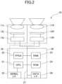
- the imaging device in the embodiment will be described with reference to FIG. 2 .
- the imaging device in the embodiment is constituted with a stereo camera 10 and an image processing board 20.
- the stereo camera 10 is constituted with two cameras attached in parallel.
- the stereo camera 10 is equipped with an image sensor 12L and an image sensor controller 13L, an image sensor 12R and an image sensor controller 13R, corresponding to a left lens 11L and a right lens 11R, respectively.
- the stereo camera 10 is constituted with two cameras, the present invention does not exclude a configuration of three or more cameras.
- the image sensor controllers 13L and 13R play a role of exposure control of the image sensors 12L and 12R, A/D conversion, control of image reading, communication with an external circuit, and transmission of image data.
- the stereo camera 10 is connected with the image processing board 20 by a data bus 27 and a serial bus 28. From the stereo camera 10, brightness image data and parallax image data are output.
- Brightness image data output from the stereo camera 10 is transmitted to the image processing board 20 from the image sensors 12L and 12R through the data bus 27. Also, the serial bus 28 changes a sensor exposure control value from the image processing board 20, changes image reading parameters, and transmits and receives a variety of setting data.
- the image processing board 20 is equipped with a CPU 21, an FPGA 22, a RAM 23, a ROM 24, a serial I/F 25, a data I/F 26, the data bus 27, and the serial bus 28.
- the CPU 21 executes controlling the entire image processing board 20, image processing, and image recognition processing.
- the FPGA 22 applies a process to image data saved in the RAM 23 that needs to be done in real time.
- the FPGA 22 generates a parallax image by executing, for example, a gamma correction, a distortion correction, namely, making right and left images parallel, and parallax calculation by block matching, and writes it back into the RAM 23.
- the CPU 21 controls the image sensor controller 13L and 13R of the stereo camera 10, and controls the image processing board 20 as a whole. Also, the CPU 21 loads a program to execute road surface shape detection, guardrail detection, and object detection from the ROM 24, and executes various processes that take as input a brightness image and a parallax image stored in the RAM 23. Furthermore, the CPU 21 outputs detected data to the outside from the serial I/F 25 or the data I/F 26.
- the CPU 21 takes, as input, information on the vehicle, such as the vehicle speed, acceleration, steering angle, and yaw rate, to use as parameters of various processes such as road surface shape detection. Data output to the outside is used as input data for executing control of the vehicle such as an automatic emergency braking and automatic speed controlling. Note that a part of the functions implemented by the CPU 21 and the FPGA 22 may be implemented outside of the image processing board 20.
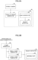
- the image processing device 40 in the embodiment is configured to include a parallax image generator 31 and an object detection device 30 as illustrated in FIG. 3A .
- the object detection device 30 is configured to include a map generator 32 and an object detector 33 as illustrated in FIG. 3A .
- the parallax image generator 31 is a parallax image generation means of generating a parallax image from a captured image captured by the stereo camera 10 consisting of two cameras as two imaging means. Functions of the parallax image generator 31 are implemented by the FPGA 22 illustrated in FIG. 2 .
- the parallax image generator 31 calculates a parallax value corresponding to an image part between captured images captured by the stereo camera 10, in order to obtain a parallax image from brightness image data obtained by the stereo camera 10.
- the parallax value here is obtained by taking one of the images captured by the stereo camera 10 as a reference image, and taking the other image as a comparison image, and calculating the amount of positional shift between the image part on the reference image and the image part on the comparison image at the same point in an imaging area. Then, by using principles of triangulation, it is possible to calculate from this parallax value the distance to the same point in the imaging area corresponding to the image part. Since the parallax value can be treated equivalent to the distance value (distance information), a parallax image will be described as an example of a distance image in the embodiment.
- a color brightness conversion is executed to obtain a brightness signal (Y) from RGB signals.
- Y 0.3 R + 0.59 G + 0.11 B
- the object detection device 30 applies a paralleled image generation process to brightness image data obtained from the stereo camera 10.
- This paralleled image generation process is a process of converting stereo images output from respective cameras into ideal paralleled stereo images that would be obtained when the two cameras are attached in parallel, from distortion in optical systems in the two cameras constituting the stereo camera 10 and from the relative positional relationship between the right and left cameras.
- the parallax image generator 31 executes a parallax image generation process of generating parallax image data.
- the parallax image generation process first, brightness image data obtained from one of the two cameras is taken as reference image data, and brightness image data obtained from the other camera is taken as comparison image data, and these data items are used to calculate the parallax between the two, so as to generate and output parallax image data.
- This parallax image data represents a parallax image in which a pixel value corresponding to the parallax value d calculated for each image part on the reference image data is represented as the pixel value of the image part.
- the parallax image generator 31 defines, on a certain line in the reference image data, a block that consists of multiple pixels, for example, 16 pixels by 1 pixel, around one pixel of interest. Meanwhile, the parallax image generator 31 defines, on the same line in the comparison image data, a block having the same size as the block defined in the reference image data; shifts the block one pixel by one pixel in the horizontal line direction; and calculates a correlation value that represents a correlation between a feature quantity that represents a feature of a pixel value in the block defined in the reference image data, and a feature quantity that represents a feature of a pixel value in each of the shifted blocks in the comparison image data.
- the parallax image generator 31 executes a matching process that selects a block in the comparison image data that has a highest correlation with the block in the reference image data among the blocks in the comparison image data. Then, the parallax image generator 31 calculates the amount of the positional shift between the pixel of interest of the block in the reference image data, and a correspondence pixel of the block of the comparison image data selected by the matching process as the parallax value d. By executing a process of calculating such a parallax value d for the entire area or a specific area of the reference image data, it is possible to obtain parallax image data.
- a block used for a matching process it is possible to use, for example, a brightness value that is a value of each pixel in the block, and as the correlation value, for example, it is possible to use the sum total of the absolute values of differences between brightness values that are values of pixels in the block in the reference image data, and brightness values that are values of corresponding pixels in the block in the comparison image data.
- a block having the minimum sum total can be considered as having the highest correlation.
- SSD Sud of Squared Difference
- ZSSD Zero-mean Sum of Squared Difference
- SAD Sum of Absolute Difference
- ZSAD Zero-mean Sum of Absolute Difference
- a parallax value can be calculated by only units of pixels, in the case where a parallax value is required at a subpixel level finer than one pixel, it is necessary to use an estimated value.
- the estimation method it is possible to use, for example, a conformal line method, a quadratic curve method, and the like.
- EEC estimated error correction
- the map generator 32 is a map generator to generate two types of maps having different resolutions, based on a parallax image generated by the parallax image generator 31.
- the functions of the map generator 32 are implemented by the CPU 21 illustrated in FIG. 2 .
- the map generator 32 generates a first map, and generates a second map in which pixels in the horizontal direction are thinned out with respect to the first map. More specifically, the map generator 32 is constituted with a V-map generator 321, a small U-map generator 322, and a large U-map generator 323 as illustrated in FIG. 3B .
- the above “first map” corresponds to a large U map
- the "second map” corresponds to a small U map.
- the object detector 33 includes a merging part 331.
- a large U map is a U map having a comparatively high resolution
- a small U map is a U map having a lower resolution in which every other pixel in the horizontal direction or the width direction is thinned out with respect to the large U map. Note that although every other pixel in the horizontal direction is thinned out here, this is merely an example.
- V-map generation process by the V-map generator 321 will be described with reference to FIGs. 4A-B .
- the V-map generator 321 generates a V map based on a parallax image generated by the parallax image generator 31.
- Generation of a V map is executed to estimate a road surface position in a parallax image, so as to recognize an object that exists on the road surface. Identifying the road surface position enables to obtain height information from the road surface, and to identify the size of an object that exists on the road surface.
- Each parallax image data item included in parallax image data is represented by a set (x, y, d) each representing an x-direction position, a y-direction position, and a parallax value d.
- the V-map generator 321 generates a two-dimensional histogram by setting d in the X-axis, y in the Y-axis, and the frequency in the Z-axis. This two-dimensional histogram corresponds to a V map. In other words, for each pixel in a parallax image, the V-map generator 321 counts up the frequency by one when a pixel having (d, y) is found in the parallax image.
- FIG. 4A is a captured image that captures a scene in which a vehicle 101 is traveling on a road surface 103 in a direction designated by an arrow C, and a utility pole 102 exists on the left side of the road surface 103.
- a V map generated from this image by the V-map generator 321 is FIG. 4B .
- FIG. 4B when converting into a V map from a parallax image, clustering parallax values at a certain height from the road surface to be associated on the V map enables to recognize an object on a road surface. Such clustering enables to recognize a vehicle 101v, a utility pole 102v, and a road surface 103v on the V map.
- An area B illustrated in slant lines in FIG. 4B in the embodiment represents a part below the road surface 103. Since no parallax is detected in a part below the road surface 103, no parallax value is associated in the area B.
- the V-map generator 321 executes a road surface shape detection process that detects a shape of the road surface 103. This is a process of linearly approximating the position estimated as a road surface on the V map.
- the method of linear approximation for example, the least-squares method or the Hough transformation may be used.
- the road surface is flat, it is possible to approximate by a single straight line, but in the case where the slope changes on the way, it is necessary to partition the map into sections to obtain precise approximation piecewise linearly.
- the polling area may be restricted as described above, or the area may be divided into two areas that are an area having greater parallaxes, and an area having smaller parallaxes to execute the road surface shape detection process.
- the V-map generator 321 executes a road surface height table calculation process that calculates and tabulates the height of the road surface 103.
- a linear equation representing the road surface is obtained from the V map, and once the parallax d has been determined, the y coordinate in that case is determined. This y coordinate represents the height of the road surface, and is tabulated in a necessary range of parallaxes.
- the U-map generator generates a U map in order to estimate the presence of, for example, a guardrail, a roadside wall, or the like along the road surface.
- the U-map generator generates two-dimensional histogram information on the X-Y with sets of values (x, y, d) each representing an x-direction position, a y-direction position, and a parallax value d for each parallax pixel data item included in parallax image data, by setting x in the X-axis, d in the Y-axis, and the frequency in the Z-axis.
- This two-dimensional histogram information is a U map.
- the U-map generator Based on the height of each road surface part tabulated in the road surface height table described above, the U-map generator generates a frequency U map for points (x, y, d) of a parallax image located within a predetermined height range from the road surface (e.g., from 20 cm to 3 m).
- FIG. 5A is a captured image that captures a state in which a vehicle 101a is traveling on the left lane in a direction designated by an arrow D on a road having one lane in each way, and a vehicle 101b is traveling on the right lane in a direction designated by an arrow E. Also, the guardrails 105a and 105b are installed on both sides of the road.
- FIG. 5B is a diagram illustrating a frequency U map converted from the captured image illustrated in FIG. 5A .
- the guardrails 105a and 105b are on straight lines extended from the right and left ends toward the top center, respectively.
- the guardrails 105a and 105b after the U map conversion are referred to as 105au and 105bu.
- the vehicle 101a and the vehicle 101b appear between the guardrails 105au and 105bu, and have a shape of a horizontal line segment connected with a slanting line in the case where a side surface of the vehicle is visible and the parallax is detected.
- the vehicle 101a and the vehicle 101b after the U map conversion are referred to as 101au and 101bu.
- FIG. 5C is a diagram representing a height U map.
- the U-map generator generates a height U map simultaneously with generation of a frequency U map.
- the U-map generator generates two-dimensional histogram information on the X-Y with sets of values (x, y, d) each representing an x-direction position, a y-direction position, and a parallax value d for each parallax pixel data item included in parallax image data, by setting x in the X-axis, d in the Y-axis, and the height from the road surface in the Z-axis.
- This two-dimensional histogram information is a height U map. The value of the height at this time is the highest height from the road surface.
- the hatching of the vehicles 101au and 101bu is darker than that of the guardrails 105au and 105bu, which implies that the height of the vehicles 101au and 101bu is higher than the height of the guardrails 105au and 105bu. This enables to use the height information of the objects for object detection.
- the U-map generator generates a real U map after having generated the U map.
- a real U-map generation process will be described with reference to FIGs. 6A-B .
- a real U map is a map obtained by converting the horizontal axis of a U map described above from the units of pixels of an image into an actual distance unit, and by converting the parallax value in the vertical axis into a thinned-out parallax to which a thinning-out rate depending on the distance is applied.
- FIG. 6A is the same diagram as FIG. 5B .
- the example illustrated here has the horizontal axis converted into the real distance, it is simply necessary to be converted into a unit corresponding to the real distance.
- the thinned-out parallax in the vertical axis is set such that no thinning out is applied to a longer distance (here, 50 m or longer), and thinning out to a half is applied to an intermediate distance (20 m or longer and less than 50 m), thinning out to one third is applied to a shorter distance (10 m or longer and less than 20 m), and thinning out to one eighth is applied to a very close distance (less than 10 m) .
- FIG. 6B is an example of a real U map generated by the U-map generator. This figure exhibits a state as if the vehicles and the like traveling on the road and the road surface are looked down from above.
- the guardrails 105au and 105bu are represented by vertical lines, and the guardrails 105au and 105bu after the conversion are referred to as 105aru and 105bru.
- the shapes of the vehicles 101au and 101bu are converted into shapes closer to the real shapes.
- the vehicles 101au and 101bu after the conversion are referred to as 101aru and 101bru.
- a small U-map generation process by the small U-map generator 322 and a large U-map generation process by the large U-map generator 323 are executed.
- a large U map generated by the large U-map generator 323 has been described as a map having a comparatively high resolution, this merely expresses a comparison with a small U map, and it may be a normal U map generated by the U-map generator described above. Note that a U map having a resolution beyond a reference value may be generated intentionally as a large U map.
- a small U-map generation process by the small U-map generator 322, which is one of the characterizing parts in the embodiment will be described later.
- the object detector 33 is an object detector that detects an object based on two types of maps generated by the map generator. In other words, the object detector 33 detects an object based on a small U map generated by the small U-map generator 322 and a large U map generated by the large U-map generator 323.
- Step S1 An object detection process by the object detector 33 will be described with reference to FIG. 7 .
- an object detection using a real U map described above will be described.
- the object detector 33 smooths a real U map (Step S1). This is to make it easier to detect an area where an object is estimated to exist (referred to as an "isolated area") by smoothing the frequency.
- an isolated area an area where an object is estimated to exist
- a target to be determined as an object through the process in the isolated area will be referred to as an "object”.
- the object detector 33 sets a threshold of binarization (Step S2). At first, the object detector 33 uses a small value (0) to binarize the real U map (Step S3). Then, the object detector 33 executes labeling of coordinates having a value, to detect an isolated area (Step S4).
- the object detector 33 determines the size of each of multiple detected isolated areas (Step S5). This determines whether the width of a detected isolated area is within the range of the size in the case where the detected target is of the type among the pedestrian to the large-sized automobile.
- the object detector 33 increments the binarizing threshold only by one (Step S2), to binarize only this object on the real U map (Step S3). Then, the object detector 33 executes labeling (Step S4), detects a smaller isolated area, and determines the size (Step S5). The object detector 33 repeatedly executes the above binarizing threshold setting process (Step S2) to the labeling process (Step S4), to detect isolated areas having desired sizes.
- the object detector 33 detects an isolated area whose frequency is higher than the surroundings on a real U map (referred to as an "island"). To detect an island, the real U map is binarized first. At first, the object detector 33 executes binarization with the threshold 0. This is because an island may be isolated, or may be connected with another island due to the height and shape of an object, partitioning of the road surface parallax, and the like, and a countermeasure is required for such cases. In other words, by binarizing the real frequency U map starting from a small threshold, it becomes possible to detect an isolated island having a suitable size at first, and then, by increasing the threshold, a connected island can be divided, to detect an isolated island having a suitable size.
- the object detector 33 uses labeling. If labeled coordinates exist around coordinates that represent the position of a pixel of interest in black, the labeling assigns the same label as the label of the pixel. If multiple labels exist, the labeling assigns a label having the smallest value and replaces the label of coordinates having other labels with the label.
- the width of this island can be considered as a width W close to the real object. An area having this width W within a predetermined range is regarded as an object candidate area.
- labeling is executed for coordinates in black after binarization, namely, coordinates whose frequency value is higher than the binarizing threshold are labeled based on the connectivity, and an area having the same label is regarded as an island.
- the object detector 33 registers the detected isolated area as an object candidate (Step S6).
- An island can be detected by using a real U map as described above.
- the width of a rectangle surrounding an island corresponds to the width of the detected object
- the height corresponds to the depth of the detected object.
- the height of the object is the maximum of the height map of the real U map.
- FIG. 8A is a diagram illustrating a real frequency U map in which rectangular areas are set to have inscribed islands registered as object candidate areas
- FIG. 8B is a diagram illustrating a parallax image having scanning ranges set corresponding to the rectangular areas in FIG. 8A
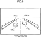
- FIG. 9 is a diagram illustrating a parallax image in which the scanning ranges in FIG. 8B have been searched to set object areas.
- the object detector 33 detects a correspondence area of a parallax image corresponding to an island detected on a real U map, in order to obtain the correct position and height of the object. It is possible to determine a range (xmin, xmax) to be detected in the parallax image from the position, width, and minimum parallax of an island detected on the real U map.
- the object detector 33 scans a set image area to extract a pixel that has a parallax value within a range of the depth of a rectangle detected as an island (the minimum parallax dmin, the maximum parallax dmax) as a candidate pixel. Then, the object detector 33 sets a line having a predetermined ratio or greater with respect to the detected width in the horizontal direction among a group of extracted candidate pixels, as a candidate line. Areas where a candidate line exists are rectangles 201a and 201b surrounding the vehicles 101aru and 101bru as illustrated in FIG. 8A .
- the object detector 33 scans in the vertical direction, and in the case of detecting candidate lines with a predetermined density or greater around a line of interest, determines the line of interest as an object line.
- the object detector 33 searches in a search area of the parallax image for an object line, determines the lowermost end and the uppermost end of the object line, and determines circumscribed rectangles 201ao and 201bo of a group of object lines, as object areas 101ao and 101bo in the parallax image.
- Table 1 is table data that specifies the size for each object type. Note that numerical values in Table 1 are merely an example.
- the unit in Table 1 is mm.
- the width is less than 1100, the height is less than 2500, and the depth is greater than 1000, the object type is set as two-wheeler.
- the width is less than 1100, the height is less than 2500, and the depth is less than 1000, the object type is set as pedestrian.
- the width is less than 1700, the height is less than 1700, and the depth is less than 10000, the object type is set as small car.
- the object type is set as standard car. Furthermore, if the width is less than 3500, the height is less than 3500, and the depth is less than 15000, the object type is set as truck. Note that an object out of any of such sizes is classified as others.
- Table 2 illustrates position, size, distance, relative velocity, and parallax information saved as current information on object data, which is used in a process of device control described with FIG. 1 .
- the position is represented by upper left coordinates (x, y) in an image;
- the size is represented by the dimensions (w, h) of an object in the image;
- the distance is represented by a distance to a photographic subject;
- the relative velocity is represented by the relative velocity per frame, or X (m/frame) laterally and Z (m/frame) in the depth direction;
- the maximum parallax is represented by the maximum parallax of the object;
- the minimum parallax is represented by the minimum parallax of the object.
- the actual height Ho of an object to be identified (referred to as an "object”, below) projected on an image area corresponding to an object area can be calculated by the following Expression [2] from the height (yomax-yomin) of the object area 101ao or 101bo determined by the object detector 33.
- Ho zo ⁇ yomax ⁇ yomin / f
- zo represents the distance between the vehicle and the object corresponding to the object area calculated from the minimum parallax value d in the object area
- "f” represents a value obtained by converting the focal length of the camera into the same unit as the unit of (yomax-yomin) .
- the actual width Wo of the object projected on the image area corresponding to the object area can be calculated by the following Expression [3] from the width (xomax-xomin) of the object area determined by the object detector 33.
- Wo zo ⁇ xomax ⁇ xomin / f
- the depth Do of the object projected on the image area corresponding to the object area can be calculated by the following Expression [4] from the maximum parallax value dmax and the minimum parallax value dmin in the isolated area corresponding to the object area.
- BF represents a product of the base length multiplied by the focal length of the stereo camera; and offset represents the parallax at infinity.
- Do BF ⁇ ( 1 / dmin ⁇ offset ⁇ 1 / dmax ⁇ offset
- the object detector 33 classifies the types of objects as in Table 1.
- the object detector 33 can determine the three-dimensional position of the object.
- the merging part 331 is a merging means of merging a large U map corresponding to a first map, and a small U map corresponding to a second map.
- the merging part 331 selects the large U map if the distance from the stereo camera 10 is within a first range.
- the merging part 331 selects the small U map if the distance from the stereo camera 10 is within a second range out of the first range.
- the "first range” is a predetermined area where the distance from the stereo camera 10 to the object is short, for example, 5 m to 10 m.
- the "second range” is a predetermined area where the distance from the stereo camera 10 to the object is long, for example, 100 m or longer. In other words, in the embodiment, the second range is the predetermined area that exists farther away from the stereo camera 10 than the first range.
- the small U-map generator 322 is a U map in which every other pixel in the horizontal direction is thinned out with respect to the large U map.
- the small U map is a map obtained by reducing the resolution of a large U map in the horizontal direction.
- FIGs. 16A-B This enables, as illustrated in FIGs. 16A-B , to detect a vehicle 401 that exists 100 m away as a single mass 401su (A), which would be detected as two separate masses 401u by using the large U map conventionally (B). Note that as illustrated in FIGs. 15A-B , if it is the case of a vehicle 301 that exists closer at around 5 m away (A), detection is possible as a single mass 301u even in the case of using the large U map.
- FIG. 10B illustrates a result of labeling on the mass 401su on a small U map generated by the small U-map generator 322.
- FIG. 11A it can be understood that in the case of clustering a distant vehicle on a large U map, it is detected as two masses of No. 0 and No. 1, and in the case of clustering the distant vehicle on a small U map, it is detected as a single mass of No. 0. In this way, in detection on a large U map, a higher resolution tends to bring a result in which a distant single object having less information is divided into two. On the other hand, in detection on a small U map, a lower resolution enables to stably detect a distant single object having less information without being divided apart.
- Step S11 Step S11
- a small U map is generated simultaneously with or after generation of a large U map by thinning out the data in the width direction at every other pixel.
- the object detector 33 executes labeling on the small U map (Step S12), and extracts a candidate area of an object having the size of, for example, a vehicle, as a mass (Step S13).
- a small U map targets an extraction of a distant vehicle
- a candidate area of an object having the size of a vehicle is extracted as a mass.
- the size of a passenger car roughly corresponds to 6 pixels in width
- the size of a large-sized vehicle corresponds to 9 pixels in width.
- the object detector 33 executes labeling on the large U map (Step S14).
- the merging part 331 merges labeling results obtained on the small U map and on the large U map, respectively (Step S15). The merging process will be described later.
- the merging part 331 executes matching for each mass having a vehicle size extracted on the small U map and the large U map (Step S21). In the embodiment, matching is executed in the horizontal direction based on the distance.
- the merging part 331 determines whether the distance is short from the stereo camera 10 to the mass as a candidate area (Step S22).
- the merging part 331 selects the mass on the large U map (Step S23) .
- the merging part 331 selects the mass on the small U map (Step S24).
- FIG. 14A is a captured image that captures a scene in which there exist a vehicle 501 and a vehicle 502 at a long distance from the stereo camera on a road surface 500, and a vehicle 503, a person 504, and a person 505 at a short distance from the stereo camera on the road surface 500.
- FIG. 14B is a small U map generated from the captured image illustrated in FIG. 14A .
- FIG. 14C is a large U map generated from the captured image illustrated in FIG. 14A .
- the merging part 331 makes a distinction between long and short on the basis of the distance from the stereo camera 10 to execute processing. In the embodiment, 5 m or shorter from the stereo cameras 10 is assumed to be short.
- the merging part 331 executes matching between the mass of S4 and the masses of [5] and [6] in consideration of the sizes in the horizontal direction in the large U map. For example, a match may be identified in the case where ⁇ 1> the difference between the center of S4, and the average of the center of [5] and the center of [6] is within a threshold, and ⁇ 2> the difference between the size of S4, and the sum of the size of [5] and the size of [6] is within a threshold.
- the mass of S1 is matched with the masses of [1] and [2] located around the same distance, and the mass of S2 is matched with the mass of [3].
- the merging part 331 selects the mass in the large U map for a mass that exists at a short distance, and selects the mass in the small U map for a mass that exists at a long distance.
- the merging part 331 selects the masses of [4], [5], and [6] in the large U map for the masses that exist at a short distance, and selects S1 and S2 in the small U map for the masses that exist at a long distance.
- detection using a large U map is executed in a short distance where an object appears large on a captured image with a comparatively greater quantity of pixel information
- detection using a small U map is executed in a long distance where an object appears small on a captured image and tends to be separated due to a comparatively less quantity of pixel information.
- the present invention is not limited as such.
- the method may be realized such that pixels are thinned out at a stage of the object detection process.
- the method may generate two parallax images having different resolutions to stably detect a distant object.
- Patent Document 1 Japanese Laid-Open Patent Publication No. 2015-207281
Claims (5)
- Dispositif de détection d'objet (3), comprenant :un générateur de carte (32) configuré pour générer, sur la base d'une image de distance qui inclut des informations de distance pour chaque coordonnée, l'image de distance étant sortie d'une caméra stéréo (10), une première carte de disparité U et une seconde carte de disparité U, la seconde carte de disparité U ayant une résolution plus basse que celle de la première carte de disparité U en enlevant un pixel sur deux dans le sens horizontal ou le sens de largeur de la première carte de disparité U ; etun détecteur d'objet (33) configuré pour détecter un objet sur la base de la première carte de disparité U et de la seconde carte de disparité U générées par le générateur de carte (32),caractérisé en ce quele détecteur d'objet (33) inclut une partie de fusionnement (331) configurée pour exécuter le fusionnement de la première carte de disparité U et de la seconde carte de disparité U, dans lequel la partie de fusionnement (331) exécute le fusionnement en sélectionnant la première carte de disparité U lorsqu'une distance depuis la caméra stéréo (10) jusqu'à l'objet, la distance étant représentée par les informations de distance, est au sein d'une première étendue prédéterminée, et en sélectionnant la seconde carte de disparité U lorsque la distance depuis la caméra stéréo (10) jusqu'à l'objet, la distance étant représentée par les informations de distance, est au sein d'une seconde étendue prédéterminée hors de la première étendue, la seconde étendue étant située plus loin de la caméra stéréo (10) que la première étendue.
- Système de commande de dispositif fixable à un véhicule (1), comprenant :le dispositif de détection d'objet (3) selon la revendication 1 ;une unité d'imagerie (2), etun appareil de commande (4) configuré pour commander un dispositif prédéterminé installé dans le véhicule (1) sur la base d'un résultat détecté par le détecteur d'objet (33).
- Procédé de détection d'objet exécuté par un ordinateur, le procédé comprenant :une étape de la génération, sur la base d'une image de distance qui inclut des informations de distance pour chaque coordonnée, l'image de distance étant sortie d'une caméra stéréo (10), d'une première carte de disparité U et d'une seconde carte de disparité U, la seconde carte de disparité U ayant une résolution plus basse que celle de la première carte de disparité U en enlevant un pixel sur deux dans le sens horizontal ou le sens de largeur de la première carte de disparité U ; etune étape de la détection d'un objet sur la base de la première carte de disparité U et de la seconde carte de disparité U générées dans l'étape de la génération,caractérisé parune étape du fusionnement de la première carte de disparité U et de la seconde carte de disparité U, dans lequel le fusionnement est exécuté en sélectionnant la première carte de disparité U lorsqu'une distance depuis la caméra stéréo (10) jusqu'à l'objet, la distance étant représentée par les informations de distance, est au sein d'une première étendue prédéterminée, et en sélectionnant la seconde carte de disparité U lorsque la distance depuis la caméra stéréo (10) jusqu'à l'objet, la distance étant représentée par les informations de distance, est au sein d'une seconde étendue prédéterminée hors de la première étendue, la seconde étendue étant située plus loin de la caméra stéréo (10) que la première étendue.
- Programme d'ordinateur comprenant des instructions qui, lorsque le programme est exécuté par un ordinateur, font en sorte que l'ordinateur réalise les étapes de :la génération, sur la base d'une image de distance qui inclut des informations de distance pour chaque coordonnée, l'image de distance étant sortie d'une caméra stéréo (10), d'une première carte de disparité U et d'une seconde carte de disparité U, la seconde carte de disparité U ayant une résolution plus basse que celle de la première carte de disparité U en enlevant un pixel sur deux dans le sens horizontal ou le sens de largeur de la première carte de disparité U ; etla détection d'un objet sur la base de la première carte de disparité U et de la seconde carte de disparité U générées dans l'étape de la génération,caractérisé en ce quelorsque le programme est exécuté par l'ordinateur, le programme fait en outre en sorte que l'ordinateur réalise l'étape du fusionnement de la première carte de disparité U et de la seconde carte de disparité U, dans lequel le fusionnement est exécuté en sélectionnant la première carte de disparité U lorsqu'une distance depuis la caméra stéréo (10) jusqu'à l'objet, la distance étant représentée par les informations de distance, est au sein d'une première étendue prédéterminée, et en sélectionnant la seconde carte de disparité U lorsque la distance depuis la caméra stéréo (10) jusqu'à l'objet, la distance étant représentée par les informations de distance, est au sein d'une seconde étendue prédéterminée hors de la première étendue, la seconde étendue étant située plus loin de la caméra stéréo (10) que la première étendue.
- Véhicule (1), comprenant :le système de commande de dispositif selon la revendication 2,dans lequel le véhicule (1) est commandé par l'appareil de commande (4).
Applications Claiming Priority (2)
| Application Number | Priority Date | Filing Date | Title |
|---|---|---|---|
| JP2016021179 | 2016-02-05 | ||
| PCT/JP2016/087253 WO2017134936A1 (fr) | 2016-02-05 | 2016-12-14 | Dispositif de détection d'objet, système de commande de dispositif, dispositif d'imagerie, procédé de détection d'objet et programme associé |
Publications (3)
| Publication Number | Publication Date |
|---|---|
| EP3413267A1 EP3413267A1 (fr) | 2018-12-12 |
| EP3413267A4 EP3413267A4 (fr) | 2019-02-13 |
| EP3413267B1 true EP3413267B1 (fr) | 2023-06-28 |
Family
ID=59500630
Family Applications (1)
| Application Number | Title | Priority Date | Filing Date |
|---|---|---|---|
| EP16889419.4A Active EP3413267B1 (fr) | 2016-02-05 | 2016-12-14 | Dispositif de détection d'objet, système de commande de dispositif, procédé de détection d'objet et programme associé |
Country Status (4)
| Country | Link |
|---|---|
| US (1) | US10853963B2 (fr) |
| EP (1) | EP3413267B1 (fr) |
| JP (1) | JP6687039B2 (fr) |
| WO (1) | WO2017134936A1 (fr) |
Families Citing this family (7)
| Publication number | Priority date | Publication date | Assignee | Title |
|---|---|---|---|---|
| JP6599014B2 (ja) * | 2016-08-26 | 2019-10-30 | オリンパス株式会社 | 計測処理装置 |
| WO2019196019A1 (fr) * | 2018-04-10 | 2019-10-17 | 深圳华大智造科技有限公司 | Procédé d'enregistrement d'image de fluorescence, instrument et système de séquençage de gènes, et support de stockage |
| JP7238422B2 (ja) | 2019-01-22 | 2023-03-14 | 株式会社リコー | 測距方法、測距装置、車載装置、移動体、測距システム |
| EP3920797A4 (fr) * | 2019-02-05 | 2022-11-02 | Electronic Caregiver, Inc. | Identification des risques d'un environnement 3d utilisant un apprentissage renforcé |
| JP7255259B2 (ja) | 2019-03-19 | 2023-04-11 | 株式会社リコー | 検出装置、測距装置、時間測定方法、プログラム、移動体 |
| JP2020190438A (ja) | 2019-05-20 | 2020-11-26 | 株式会社リコー | 計測装置および計測システム |
| CN113298820B (zh) * | 2020-12-01 | 2022-08-26 | 湖南长天自控工程有限公司 | 一种料堆盘库的方法及系统 |
Family Cites Families (30)
| Publication number | Priority date | Publication date | Assignee | Title |
|---|---|---|---|---|
| JP3466661B2 (ja) | 1993-06-29 | 2003-11-17 | キヤノン株式会社 | 画像処理装置及びその方法 |
| JP4274071B2 (ja) * | 2004-07-26 | 2009-06-03 | トヨタ自動車株式会社 | 物体検出装置 |
| JP2006134035A (ja) | 2004-11-05 | 2006-05-25 | Fuji Heavy Ind Ltd | 移動物体検出装置および移動物体検出方法 |
| JP4341564B2 (ja) * | 2005-02-25 | 2009-10-07 | 株式会社豊田中央研究所 | 対象物判定装置 |
| JP4719543B2 (ja) | 2005-09-26 | 2011-07-06 | 株式会社リコー | ワークフローシステム、サーバ装置、ワークフローシステムの処理方法及びワークフロープログラム |
| JP2007102545A (ja) | 2005-10-05 | 2007-04-19 | Ricoh Co Ltd | 電子文書作成装置、電子文書作成方法及び電子文書作成プログラム |
| JP4647515B2 (ja) | 2006-02-20 | 2011-03-09 | 株式会社リコー | 座標検出装置、筆記具および座標入力システム |
| JP5316805B2 (ja) | 2009-03-16 | 2013-10-16 | 株式会社リコー | 車載カメラ装置の画像調整装置及び車載カメラ装置 |
| JP5376313B2 (ja) | 2009-09-03 | 2013-12-25 | 株式会社リコー | 画像処理装置及び画像撮像装置 |
| JP5664152B2 (ja) | 2009-12-25 | 2015-02-04 | 株式会社リコー | 撮像装置、車載用撮像システム及び物体識別装置 |
| KR20120023431A (ko) * | 2010-09-03 | 2012-03-13 | 삼성전자주식회사 | 깊이 조정이 가능한 2차원/3차원 영상 변환 방법 및 그 장치 |
| JP6102088B2 (ja) | 2011-09-01 | 2017-03-29 | 株式会社リコー | 画像投影装置、画像処理装置、画像投影方法、画像投影方法のプログラム及びそのプログラムを記録した記録媒体 |
| JP5867207B2 (ja) * | 2012-03-16 | 2016-02-24 | 株式会社リコー | 画像処理装置、画像処理システム及び画像処理方法 |
| JP2013250907A (ja) * | 2012-06-04 | 2013-12-12 | Ricoh Co Ltd | 視差算出装置、視差算出方法及び視差算出用プログラム |
| JP2014131257A (ja) | 2012-11-27 | 2014-07-10 | Ricoh Co Ltd | 画像補正システム、画像補正方法及びプログラム |
| RU2012154657A (ru) * | 2012-12-17 | 2014-06-27 | ЭлЭсАй Корпорейшн | Способы и устройство для объединения изображений с глубиной, генерированных с использованием разных способов формирования изображений с глубиной |
| JP6150277B2 (ja) * | 2013-01-07 | 2017-06-21 | 国立研究開発法人情報通信研究機構 | 立体映像符号化装置、立体映像復号化装置、立体映像符号化方法、立体映像復号化方法、立体映像符号化プログラム及び立体映像復号化プログラム |
| JP6274557B2 (ja) | 2013-02-18 | 2018-02-07 | 株式会社リコー | 移動面情報検出装置、及びこれを用いた移動体機器制御システム並びに移動面情報検出用プログラム |
| US9519972B2 (en) * | 2013-03-13 | 2016-12-13 | Kip Peli P1 Lp | Systems and methods for synthesizing images from image data captured by an array camera using restricted depth of field depth maps in which depth estimation precision varies |
| JP6245885B2 (ja) * | 2013-08-02 | 2017-12-13 | キヤノン株式会社 | 撮像装置およびその制御方法 |
| JP6398347B2 (ja) | 2013-08-15 | 2018-10-03 | 株式会社リコー | 画像処理装置、認識対象物検出方法、認識対象物検出プログラム、および、移動体制御システム |
| JP6417886B2 (ja) | 2013-12-12 | 2018-11-07 | 株式会社リコー | 視差値導出装置、移動体、ロボット、視差値生産方法、及びプログラム |
| JP6519262B2 (ja) * | 2014-04-10 | 2019-05-29 | 株式会社リコー | 立体物検出装置、立体物検出方法、立体物検出プログラム、及び移動体機器制御システム |
| JP2016001170A (ja) | 2014-05-19 | 2016-01-07 | 株式会社リコー | 処理装置、処理プログラム、及び、処理方法 |
| JP2016001464A (ja) | 2014-05-19 | 2016-01-07 | 株式会社リコー | 処理装置、処理システム、処理プログラム、及び、処理方法 |
| JP6417729B2 (ja) | 2014-06-09 | 2018-11-07 | 株式会社リコー | 画像処理装置、画像処理方法、プログラム、視差データの生産方法、機器制御システム |
| JP6550881B2 (ja) | 2014-07-14 | 2019-07-31 | 株式会社リコー | 立体物検出装置、立体物検出方法、立体物検出プログラム、及び移動体機器制御システム |
| US20160019429A1 (en) | 2014-07-17 | 2016-01-21 | Tomoko Ishigaki | Image processing apparatus, solid object detection method, solid object detection program, and moving object control system |
| US9726604B2 (en) | 2014-11-12 | 2017-08-08 | Ricoh Company, Ltd. | Adhering detection apparatus, adhering substance detection method, storage medium, and device control system for controlling vehicle-mounted devices |
| PL411602A1 (pl) * | 2015-03-17 | 2016-09-26 | Politechnika Poznańska | System do estymacji ruchu na obrazie wideo i sposób estymacji ruchu na obrazie wideo |
-
2016
- 2016-12-14 JP JP2017565422A patent/JP6687039B2/ja active Active
- 2016-12-14 WO PCT/JP2016/087253 patent/WO2017134936A1/fr active Application Filing
- 2016-12-14 EP EP16889419.4A patent/EP3413267B1/fr active Active
-
2018
- 2018-08-01 US US16/051,882 patent/US10853963B2/en active Active
Also Published As
| Publication number | Publication date |
|---|---|
| EP3413267A1 (fr) | 2018-12-12 |
| EP3413267A4 (fr) | 2019-02-13 |
| JP6687039B2 (ja) | 2020-04-22 |
| JPWO2017134936A1 (ja) | 2018-11-22 |
| WO2017134936A1 (fr) | 2017-08-10 |
| US10853963B2 (en) | 2020-12-01 |
| US20180357783A1 (en) | 2018-12-13 |
Similar Documents
| Publication | Publication Date | Title |
|---|---|---|
| EP3413267B1 (fr) | Dispositif de détection d'objet, système de commande de dispositif, procédé de détection d'objet et programme associé | |
| US10984509B2 (en) | Image processing apparatus, imaging device, moving body device control system, image information processing method, and program product | |
| US10860867B2 (en) | Image processing apparatus, imaging apparatus, mobile device control system, and recording medium | |
| US10755116B2 (en) | Image processing apparatus, imaging apparatus, and device control system | |
| EP2889641B1 (fr) | Appareil, procédé, programme et système de traitement d'images | |
| US11064177B2 (en) | Image processing apparatus, imaging apparatus, mobile device control system, image processing method, and recording medium | |
| EP2461305B1 (fr) | Dispositif de reconnaissance de forme de route | |
| JP3463858B2 (ja) | 周辺監視装置及び方法 | |
| EP2775423A2 (fr) | Appareil de détection d'objet, système de commande de dispositif embarqué et support de programme de détection d'objet | |
| US10679388B2 (en) | Image processing apparatus, device control system, imaging apparatus, and recording medium | |
| US10776633B2 (en) | Image processing apparatus, imaging apparatus, mobile device control system, and recording medium | |
| US11691585B2 (en) | Image processing apparatus, imaging device, moving body device control system, image processing method, and program product | |
| US10628960B2 (en) | Information processing apparatus, imaging apparatus, device control system, moving object, information processing method, and recording medium | |
| EP2936386B1 (fr) | Procédé de détection d'objet cible basé sur image de appareil photo par regroupement de multiples cellules d'image adjacentes, dispositif appareil photo et véhicule motorisé | |
| CN111971682A (zh) | 路面检测装置、利用了路面检测装置的图像显示装置、利用了路面检测装置的障碍物检测装置、路面检测方法、利用了路面检测方法的图像显示方法以及利用了路面检测方法的障碍物检测方法 | |
| US20210286082A1 (en) | Distance measuring device and distance measuring device control method | |
| US11054245B2 (en) | Image processing apparatus, device control system, imaging apparatus, image processing method, and recording medium | |
| EP4060643A1 (fr) | Procédé de reconnaissance de feu de circulation et dispositif de reconnaissance de feu de circulation | |
| Nedevschi et al. | Stereovision-based sensor for intersection assistance | |
| EP3287948B1 (fr) | Appareil de traitement d'images, système de commande d'appareil de corps mobile, procédé de traitement d'images et programme | |
| EP3330893A1 (fr) | Dispositif et procédé de traitement d'informations et moyens de support | |
| JP6943092B2 (ja) | 情報処理装置、撮像装置、機器制御システム、移動体、情報処理方法、及び、情報処理プログラム | |
| CN111914610B (zh) | 立体物检测装置、以及立体物检测方法 | |
| Nedevschi et al. | On-board stereo sensor for intersection driving assistance architecture and specification | |
| Vestri et al. | Real-time monocular 3D vision system |
Legal Events
| Date | Code | Title | Description |
|---|---|---|---|
| STAA | Information on the status of an ep patent application or granted ep patent |
Free format text: STATUS: THE INTERNATIONAL PUBLICATION HAS BEEN MADE |
|
| PUAI | Public reference made under article 153(3) epc to a published international application that has entered the european phase |
Free format text: ORIGINAL CODE: 0009012 |
|
| STAA | Information on the status of an ep patent application or granted ep patent |
Free format text: STATUS: REQUEST FOR EXAMINATION WAS MADE |
|
| 17P | Request for examination filed |
Effective date: 20180726 |
|
| AK | Designated contracting states |
Kind code of ref document: A1 Designated state(s): AL AT BE BG CH CY CZ DE DK EE ES FI FR GB GR HR HU IE IS IT LI LT LU LV MC MK MT NL NO PL PT RO RS SE SI SK SM TR |
|
| AX | Request for extension of the european patent |
Extension state: BA ME |
|
| A4 | Supplementary search report drawn up and despatched |
Effective date: 20190111 |
|
| RIC1 | Information provided on ipc code assigned before grant |
Ipc: G01B 11/00 20060101ALN20190107BHEP Ipc: B60R 21/00 20060101ALN20190107BHEP Ipc: G06T 7/00 20170101ALN20190107BHEP Ipc: G08G 1/16 20060101ALN20190107BHEP Ipc: G06K 9/00 20060101AFI20190107BHEP Ipc: G01C 3/06 20060101ALN20190107BHEP |
|
| DAV | Request for validation of the european patent (deleted) | ||
| DAX | Request for extension of the european patent (deleted) | ||
| STAA | Information on the status of an ep patent application or granted ep patent |
Free format text: STATUS: EXAMINATION IS IN PROGRESS |
|
| 17Q | First examination report despatched |
Effective date: 20190827 |
|
| STAA | Information on the status of an ep patent application or granted ep patent |
Free format text: STATUS: EXAMINATION IS IN PROGRESS |
|
| STAA | Information on the status of an ep patent application or granted ep patent |
Free format text: STATUS: EXAMINATION IS IN PROGRESS |
|
| RIC1 | Information provided on ipc code assigned before grant |
Ipc: G08G 1/16 20060101ALN20221007BHEP Ipc: G01C 3/06 20060101ALN20221007BHEP Ipc: G01B 11/00 20060101ALN20221007BHEP Ipc: B60R 21/00 20060101ALN20221007BHEP Ipc: G06T 7/00 20170101ALN20221007BHEP Ipc: G06V 20/58 20220101AFI20221007BHEP |
|
| REG | Reference to a national code |
Ref country code: DE Ref legal event code: R079 Ref document number: 602016080714 Country of ref document: DE Free format text: PREVIOUS MAIN CLASS: G06T0007000000 Ipc: G06V0020580000 Ref country code: DE Ref legal event code: R079 Free format text: PREVIOUS MAIN CLASS: G06T0007000000 Ipc: G06V0020580000 |
|
| RIC1 | Information provided on ipc code assigned before grant |
Ipc: G08G 1/16 20060101ALN20221205BHEP Ipc: G01C 3/06 20060101ALN20221205BHEP Ipc: G01B 11/00 20060101ALN20221205BHEP Ipc: B60R 21/00 20060101ALN20221205BHEP Ipc: G06T 7/00 20170101ALN20221205BHEP Ipc: G06V 20/58 20220101AFI20221205BHEP |
|
| RIC1 | Information provided on ipc code assigned before grant |
Ipc: G08G 1/16 20060101ALN20221215BHEP Ipc: G01C 3/06 20060101ALN20221215BHEP Ipc: G01B 11/00 20060101ALN20221215BHEP Ipc: B60R 21/00 20060101ALN20221215BHEP Ipc: G06T 7/00 20170101ALN20221215BHEP Ipc: G06V 20/58 20220101AFI20221215BHEP |
|
| GRAP | Despatch of communication of intention to grant a patent |
Free format text: ORIGINAL CODE: EPIDOSNIGR1 |
|
| STAA | Information on the status of an ep patent application or granted ep patent |
Free format text: STATUS: GRANT OF PATENT IS INTENDED |
|
| INTG | Intention to grant announced |
Effective date: 20230124 |
|
| GRAS | Grant fee paid |
Free format text: ORIGINAL CODE: EPIDOSNIGR3 |
|
| GRAA | (expected) grant |
Free format text: ORIGINAL CODE: 0009210 |
|
| STAA | Information on the status of an ep patent application or granted ep patent |
Free format text: STATUS: THE PATENT HAS BEEN GRANTED |
|
| P01 | Opt-out of the competence of the unified patent court (upc) registered |
Effective date: 20230517 |
|
| AK | Designated contracting states |
Kind code of ref document: B1 Designated state(s): AL AT BE BG CH CY CZ DE DK EE ES FI FR GB GR HR HU IE IS IT LI LT LU LV MC MK MT NL NO PL PT RO RS SE SI SK SM TR |
|
| REG | Reference to a national code |
Ref country code: CH Ref legal event code: EP |
|
| REG | Reference to a national code |
Ref country code: AT Ref legal event code: REF Ref document number: 1583408 Country of ref document: AT Kind code of ref document: T Effective date: 20230715 |
|
| REG | Reference to a national code |
Ref country code: IE Ref legal event code: FG4D |
|
| REG | Reference to a national code |
Ref country code: DE Ref legal event code: R096 Ref document number: 602016080714 Country of ref document: DE |
|
| REG | Reference to a national code |
Ref country code: LT Ref legal event code: MG9D |
|
| PG25 | Lapsed in a contracting state [announced via postgrant information from national office to epo] |
Ref country code: SE Free format text: LAPSE BECAUSE OF FAILURE TO SUBMIT A TRANSLATION OF THE DESCRIPTION OR TO PAY THE FEE WITHIN THE PRESCRIBED TIME-LIMIT Effective date: 20230628 Ref country code: NO Free format text: LAPSE BECAUSE OF FAILURE TO SUBMIT A TRANSLATION OF THE DESCRIPTION OR TO PAY THE FEE WITHIN THE PRESCRIBED TIME-LIMIT Effective date: 20230928 |
|
| REG | Reference to a national code |
Ref country code: NL Ref legal event code: MP Effective date: 20230628 |
|
| REG | Reference to a national code |
Ref country code: AT Ref legal event code: MK05 Ref document number: 1583408 Country of ref document: AT Kind code of ref document: T Effective date: 20230628 |
|
| PG25 | Lapsed in a contracting state [announced via postgrant information from national office to epo] |
Ref country code: RS Free format text: LAPSE BECAUSE OF FAILURE TO SUBMIT A TRANSLATION OF THE DESCRIPTION OR TO PAY THE FEE WITHIN THE PRESCRIBED TIME-LIMIT Effective date: 20230628 Ref country code: NL Free format text: LAPSE BECAUSE OF FAILURE TO SUBMIT A TRANSLATION OF THE DESCRIPTION OR TO PAY THE FEE WITHIN THE PRESCRIBED TIME-LIMIT Effective date: 20230628 Ref country code: LV Free format text: LAPSE BECAUSE OF FAILURE TO SUBMIT A TRANSLATION OF THE DESCRIPTION OR TO PAY THE FEE WITHIN THE PRESCRIBED TIME-LIMIT Effective date: 20230628 Ref country code: LT Free format text: LAPSE BECAUSE OF FAILURE TO SUBMIT A TRANSLATION OF THE DESCRIPTION OR TO PAY THE FEE WITHIN THE PRESCRIBED TIME-LIMIT Effective date: 20230628 Ref country code: HR Free format text: LAPSE BECAUSE OF FAILURE TO SUBMIT A TRANSLATION OF THE DESCRIPTION OR TO PAY THE FEE WITHIN THE PRESCRIBED TIME-LIMIT Effective date: 20230628 Ref country code: GR Free format text: LAPSE BECAUSE OF FAILURE TO SUBMIT A TRANSLATION OF THE DESCRIPTION OR TO PAY THE FEE WITHIN THE PRESCRIBED TIME-LIMIT Effective date: 20230929 |
|
| PG25 | Lapsed in a contracting state [announced via postgrant information from national office to epo] |
Ref country code: FI Free format text: LAPSE BECAUSE OF FAILURE TO SUBMIT A TRANSLATION OF THE DESCRIPTION OR TO PAY THE FEE WITHIN THE PRESCRIBED TIME-LIMIT Effective date: 20230628 |
|
| PG25 | Lapsed in a contracting state [announced via postgrant information from national office to epo] |
Ref country code: SK Free format text: LAPSE BECAUSE OF FAILURE TO SUBMIT A TRANSLATION OF THE DESCRIPTION OR TO PAY THE FEE WITHIN THE PRESCRIBED TIME-LIMIT Effective date: 20230628 |
|
| PGFP | Annual fee paid to national office [announced via postgrant information from national office to epo] |
Ref country code: GB Payment date: 20231220 Year of fee payment: 8 |
|
| PG25 | Lapsed in a contracting state [announced via postgrant information from national office to epo] |
Ref country code: ES Free format text: LAPSE BECAUSE OF FAILURE TO SUBMIT A TRANSLATION OF THE DESCRIPTION OR TO PAY THE FEE WITHIN THE PRESCRIBED TIME-LIMIT Effective date: 20230628 |
|
| PG25 | Lapsed in a contracting state [announced via postgrant information from national office to epo] |
Ref country code: IS Free format text: LAPSE BECAUSE OF FAILURE TO SUBMIT A TRANSLATION OF THE DESCRIPTION OR TO PAY THE FEE WITHIN THE PRESCRIBED TIME-LIMIT Effective date: 20231028 |
|
| PG25 | Lapsed in a contracting state [announced via postgrant information from national office to epo] |
Ref country code: SM Free format text: LAPSE BECAUSE OF FAILURE TO SUBMIT A TRANSLATION OF THE DESCRIPTION OR TO PAY THE FEE WITHIN THE PRESCRIBED TIME-LIMIT Effective date: 20230628 Ref country code: SK Free format text: LAPSE BECAUSE OF FAILURE TO SUBMIT A TRANSLATION OF THE DESCRIPTION OR TO PAY THE FEE WITHIN THE PRESCRIBED TIME-LIMIT Effective date: 20230628 Ref country code: RO Free format text: LAPSE BECAUSE OF FAILURE TO SUBMIT A TRANSLATION OF THE DESCRIPTION OR TO PAY THE FEE WITHIN THE PRESCRIBED TIME-LIMIT Effective date: 20230628 Ref country code: PT Free format text: LAPSE BECAUSE OF FAILURE TO SUBMIT A TRANSLATION OF THE DESCRIPTION OR TO PAY THE FEE WITHIN THE PRESCRIBED TIME-LIMIT Effective date: 20231030 Ref country code: IS Free format text: LAPSE BECAUSE OF FAILURE TO SUBMIT A TRANSLATION OF THE DESCRIPTION OR TO PAY THE FEE WITHIN THE PRESCRIBED TIME-LIMIT Effective date: 20231028 Ref country code: ES Free format text: LAPSE BECAUSE OF FAILURE TO SUBMIT A TRANSLATION OF THE DESCRIPTION OR TO PAY THE FEE WITHIN THE PRESCRIBED TIME-LIMIT Effective date: 20230628 Ref country code: EE Free format text: LAPSE BECAUSE OF FAILURE TO SUBMIT A TRANSLATION OF THE DESCRIPTION OR TO PAY THE FEE WITHIN THE PRESCRIBED TIME-LIMIT Effective date: 20230628 Ref country code: CZ Free format text: LAPSE BECAUSE OF FAILURE TO SUBMIT A TRANSLATION OF THE DESCRIPTION OR TO PAY THE FEE WITHIN THE PRESCRIBED TIME-LIMIT Effective date: 20230628 Ref country code: AT Free format text: LAPSE BECAUSE OF FAILURE TO SUBMIT A TRANSLATION OF THE DESCRIPTION OR TO PAY THE FEE WITHIN THE PRESCRIBED TIME-LIMIT Effective date: 20230628 |
|
| PGFP | Annual fee paid to national office [announced via postgrant information from national office to epo] |
Ref country code: IT Payment date: 20231228 Year of fee payment: 8 Ref country code: FR Payment date: 20231222 Year of fee payment: 8 Ref country code: DE Payment date: 20231214 Year of fee payment: 8 |
|
| PG25 | Lapsed in a contracting state [announced via postgrant information from national office to epo] |
Ref country code: PL Free format text: LAPSE BECAUSE OF FAILURE TO SUBMIT A TRANSLATION OF THE DESCRIPTION OR TO PAY THE FEE WITHIN THE PRESCRIBED TIME-LIMIT Effective date: 20230628 |
|
| PG25 | Lapsed in a contracting state [announced via postgrant information from national office to epo] |
Ref country code: DK Free format text: LAPSE BECAUSE OF FAILURE TO SUBMIT A TRANSLATION OF THE DESCRIPTION OR TO PAY THE FEE WITHIN THE PRESCRIBED TIME-LIMIT Effective date: 20230628 |
|
| PLBE | No opposition filed within time limit |
Free format text: ORIGINAL CODE: 0009261 |
|
| STAA | Information on the status of an ep patent application or granted ep patent |
Free format text: STATUS: NO OPPOSITION FILED WITHIN TIME LIMIT |