EP3412371A1 - Bandlagervorrichtung - Google Patents
Bandlagervorrichtung Download PDFInfo
- Publication number
- EP3412371A1 EP3412371A1 EP18174777.5A EP18174777A EP3412371A1 EP 3412371 A1 EP3412371 A1 EP 3412371A1 EP 18174777 A EP18174777 A EP 18174777A EP 3412371 A1 EP3412371 A1 EP 3412371A1
- Authority
- EP
- European Patent Office
- Prior art keywords
- inner cylinder
- bearing device
- central axis
- band bearing
- blanks
- Prior art date
- Legal status (The legal status is an assumption and is not a legal conclusion. Google has not performed a legal analysis and makes no representation as to the accuracy of the status listed.)
- Granted
Links
Images

Classifications
-
- B—PERFORMING OPERATIONS; TRANSPORTING
- B21—MECHANICAL METAL-WORKING WITHOUT ESSENTIALLY REMOVING MATERIAL; PUNCHING METAL
- B21C—MANUFACTURE OF METAL SHEETS, WIRE, RODS, TUBES, PROFILES OR LIKE SEMI-MANUFACTURED PRODUCTS OTHERWISE THAN BY ROLLING; AUXILIARY OPERATIONS USED IN CONNECTION WITH METAL-WORKING WITHOUT ESSENTIALLY REMOVING MATERIAL
- B21C47/00—Winding-up, coiling or winding-off metal wire, metal band or other flexible metal material characterised by features relevant to metal processing only
- B21C47/28—Drums or other coil-holders
-
- B—PERFORMING OPERATIONS; TRANSPORTING
- B65—CONVEYING; PACKING; STORING; HANDLING THIN OR FILAMENTARY MATERIAL
- B65H—HANDLING THIN OR FILAMENTARY MATERIAL, e.g. SHEETS, WEBS, CABLES
- B65H75/00—Storing webs, tapes, or filamentary material, e.g. on reels
- B65H75/02—Cores, formers, supports, or holders for coiled, wound, or folded material, e.g. reels, spindles, bobbins, cop tubes, cans, mandrels or chucks
- B65H75/04—Kinds or types
- B65H75/08—Kinds or types of circular or polygonal cross-section
- B65H75/14—Kinds or types of circular or polygonal cross-section with two end flanges
- B65H75/145—Reinforcement or protection arrangements for the peripheral edge of the flanges
-
- B—PERFORMING OPERATIONS; TRANSPORTING
- B65—CONVEYING; PACKING; STORING; HANDLING THIN OR FILAMENTARY MATERIAL
- B65H—HANDLING THIN OR FILAMENTARY MATERIAL, e.g. SHEETS, WEBS, CABLES
- B65H2701/00—Handled material; Storage means
- B65H2701/50—Storage means for webs, tapes, or filamentary material
- B65H2701/53—Adaptations of cores or reels for special purposes
- B65H2701/534—Stackable or interlockable reels or parts of reels
Definitions
- the invention relates to a tape storage device for storage and easy handling of a metal strip, in particular a band of stamped parts.
- the invention is therefore based on the object to overcome the abovementioned disadvantages and to provide a reusable tape storage device with which a tape can be stored, transported or further processed.
- the tape storage device should be safe and easy to handle.
- a tape storage device is proposed.
- the band bearing device has a hollow inner cylinder with a central axis X and two end shrouds surrounding a circumferential surface of the inner cylinder in each case in a direction along the central axis X, arranged symmetrically to the central axis X.
- the inner cylinder or the radially outwardly of the central axis X outwardly directed lateral surface of the inner cylinder forms the support surface for the tape on the tape storage device.
- the band or metal band is wound around the inner cylinder or around its lateral surface, wherein the inner cylinder has a height substantially corresponding to the width of the metal strip, so that the metal strip between the end blanks on the lateral surface can be wound and no or has only a slight play on the inner cylinder.
- the height of the inner cylinder is limited in both directions along the central axis by the end blanks, so that a stop is formed by the end blanks in both directions along the central axis X for the voltage applied to the inner cylinder belt.
- the end blanks each have a end condenser diameter that is larger than an inside cylinder diameter of the inside cylinder.
- the end condenser diameter of the end blanks are equal to and greater than the metal strip wound around the inner cylinder so that the end blanks project beyond the wound metal strip and provide protection against mechanical impact on the metal strip.
- the end blanks are each connected via at least one connecting means with the inner cylinder, so that they are fixed to the inner cylinder.
- the inner cylinder, the end blanks, and connecting means connecting them are formed of a heat-resistant material at least up to 1400 ° C to 1800 ° C, so that the band bearing apparatus can pick up a metal band still hot by the production process, or heat-treat the metal band in its wound state on the band bearing apparatus can be.
- the band bearing device has in a respective outer edge region of the end blanks between the end blanks at least one retaining element which extends between the end blanks and is releasably connected at its respective ends to the respective end blade.
- the at least one retaining element serves on the one hand to protect and fix the metal strip, which does not unwind through the retaining element and can not come into direct contact with the environment, and on the other hand the protection of the band bearing device and in particular the holding of the distance between the end blanks.
- the distance of the end blanks is determined in its inner region by the inner cylinder and in its outer edge region by the at least one retaining element, so that the distance of the end blanks is maintained even under mechanical action in the outer edge region. A mechanical deformation, such as bending, is made difficult or prevented, whereby a repair of the band bearing device, for example by aligning and bending back the end blanks, can be omitted.
- a belt stored on or with the band bearing device is wound on the outwardly directed lateral surface of the inner cylinder between the end blanks and does not protrude beyond the end blanks.
- the end blanks are essentially round, flat and cut-out panes.
- the at least one connecting means is in each case a weld seam running around the lateral surface of the inner cylinder or a multiplicity of welding points which are arranged rotationally symmetrically about the central axis X.
- the weld or welds are heat resistant, so that the cohesion of the tape storage device is not affected in a temperature treatment of the stored on the tape storage device tape.
- the end blanks and / or the inner cylinder have cutouts in an advantageous embodiment variant.
- the cutouts are arranged symmetrically about the central axis X.
- Two directly adjacent cut-outs on one of the end rims have a holding bridge between them.
- the retaining web lies on the wall of the inner cylinder and directly adjacent to the lateral surface of the inner cylinder and extends in the radial direction over the wall or the lateral surface to the outside.
- the holding web forms a stop for the metal strip directly on the lateral surface, so that the metal strip can not slip off the inner cylinder.
- the portions of the end-free end blanks extending outwardly from the peripheral surface of the inner cylinder to the respective outer peripheral portions of the end blanks form a stopper for the metal strip in a portion spaced from the Inn cylinder. Through the cutouts an effective stop for the metal strip is formed while reducing the weight of the tape storage device.
- the tape storage device forms in a further advantageous embodiment handling openings.
- the end blanks each have in their center and / or in a round, centered to the central axis X inner region, which has a smaller diameter than the inner cylinder, the handling openings.
- a handling opening on the end blanks is in each case opposite a handling opening on the respective other end blank, so that a tool can reach through the handling openings and through the band bearing devices.
- Circular handling openings arranged in the center of the end blanks are used, for example, to receive a mandrel which can serve as a support for the band bearing device and around which the band bearing device is rotatably mounted in order to unwind or wind up the metal band.
- Elongated handling openings or a plurality of round handling openings may serve to fix in the circumferential direction about the central axis X, so that the band bearing device is not or only is controlled to rotate, thereby preventing uncontrolled unwinding and a risk of injury is minimized.
- the at least one holding element forms at its ends on each end of the closing edge a respective resilient latching tab on the outside of the respective end blank and a counter-tab located on the inside of the respective end blank and arranged between the end blanks.
- the counter-tabs are used to maintain the distance between the end shrouds at compression forces on the end shrouds and the detent tabs to maintain the distance between the end shrouds at tensile forces on the end shims.
- the latching tab is used to releasably attach the at least one retaining element to the end blanks.
- the end blanks each form a receptacle for receiving a respective holding element.
- the receptacle is formed in the respective outer edge region of an end blank and has a latching web on which the retaining element can be latched or latched by the respective latching tab.
- the end blanks form a plurality of receptacles, wherein in each case two receptacles lying opposite one another on the end blanks receive a holding element.
- the latching web divides a respective receptacle into an upper and a lower portion, wherein the lower portion is hole-shaped and completely bounded by the counselronde and the detent web and the upper portion outbreak-shaped and bounded by the counselronde and the detent web on three sides and to one side out, in the radial direction from the central axis X, is open to the outside.
- the end blanks have phases at their edges, so that the tape storage device is safe to touch and a person can not be injured in a degree or sharp, un-pasty edges when handling the tape storage device.
- a further advantageous development of the band bearing device provides that two holding elements are connected to a cover strip.
- the band bearing device has for this purpose at least two holding elements, wherein in each case a holding element is connected to at least one further holding element, which is arranged directly adjacent to the end blanks, by a particular elastically formed cover strip.
- the cover strip covers the wound on the inner cylinder metal strip to the outside, so that a contact and contact protection is formed. Dirt particles, such as dust or grease particles, that the Metal strip could contaminate, can not reach through the masking tape on the metal strip. A cleaning, such as degreasing before a temperature treatment, can be omitted.
- the cover strip is also releasably fixable to the holding elements and may be formed, for example, as an annular band, which is arranged around the end blanks and held by the holding elements.
- the cover strip can be fixed to the holding elements, for example by gluing, clamping or by a Velcro strip or be formed with connectable ends, which are connected to each other by releasable connecting pieces such as a hook and loop fastener.
- the tape storage device has a tape attachment means on the inner cylinder.
- the band fastening means may for example be a screw connection, with which the metal band is fixed to the Innzylinder.
- the band attachment means is an L-shaped projection, wherein a short L-leg extends radially away from the inner cylinder and a long L-leg, which kinks from the short L-leg, extends circumferentially around the outer surface of the inner cylinder.
- a resilient clamping plate is arranged that a beginning or end portion of the metal strip, between the covered portion of the lateral surface and the long L-leg lies or is inserted, jammed and thus releasably fixed.
- the respective edges of the L-shaped projection are formed with a radius and form a smooth transition between the inner cylinder and the beginning and end portion of the metal bands.
- the tape storage device has a plurality of releasable holding elements extending between the end blanks.
- the holding elements of the plurality are arranged uniformly distributed about the central axis X on an outer periphery of the end blanks.
- the at least one retaining element is injection-molded from at least temperature-resistant plastic to a temperature of 200 ° C., so that it does not have to be removed when the band bearing device is heated, but can remain on the end blanks.
- FIG. 1 shows the band bearing device 1 from a side view, wherein the band bearing device 1 is shown cut by the inner cylinder 11, so that from the side view, one of the end blanks 12 and the cut inner cylinder 11 can be seen.
- the inner cylinder 11 is connected to the counselronde by the four welds 14, which are arranged in each case rotated about the central axis X to each other by 90 °.
- the inner cylinder 11 has an inner cylinder diameter D11.
- the handling openings 17 are arranged in a region of the end blank 12, which has a smaller diameter than the inner cylinder diameter D11.
- a central, round handling opening 17 is surrounded by four, likewise round handling openings, which are aligned like the welding points 14.
- An additional elongate handling opening 17 is disposed between the central handling opening and one of the round handling openings surrounding the central handling opening.
- the end blank 12 has eight material-free cutouts 15.
- Four material-free cutouts 15 are formed in an annular region within the inner cylinder diameter D11 and four material-free cutouts 15 in an annular region outside the Inner cylinder diameter D11 but formed within the end diameter D12.
- the holding web 16 is symmetrical to the wall which forms the lateral surface of the inner cylinder 11, so that all retaining webs 16 together form a substantially annular delimitation on the inner cylinder 11.
- eight receptacles 18 are distributed symmetrically about the central axis X.
- FIG. 2 a band bearing device is seen from a plan view, so that the limitation of the height H by the two end blanks 12 is visible.
- the end blanks 12 are each arranged in a direction along the central axis X on the inner cylinder 11.
- FIG. 2 further shows the retaining elements 13 which hold the spacing of the end blanks 12 under tensile or compressive forces.
- FIG. 3 shows an enlarged detail view of a retaining element 13 on the end blanks 12.
- the inside abutting the respective end blanks 12 opposite tabs 132 serve to support the end blanks 12 against pressure load, the mating tabs 132 are supported against each other by the stiffening rib 133.
- the latching tabs 131 are on the outside of the final blanks 12, wherein they engage by a locking lugs 134 in the receptacles 18 and in the lower portion 182.
- FIG. 4 is a detailed view of a receptacle 18 with a latching web 181.
- the receptacle 18 is divided by the latching web in a lower portion 182 and an upper portion 183.
- the locking lugs 134 of the holding elements 13 each engage in the lower portion 182.
- the upper portion 183 receives the holding members 13 so that the end-of-round diameter D12 is not enlarged by the holding members 13.
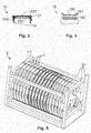
- FIG. 5 there is shown a transport device 2 for seventeen tape storage devices 1, which is not part of the invention.
- the tape storage devices 1 are arranged side by side in the cage-like transport device 2 along a common center axis X.
- the transport device 2 protects the tape storage devices 1 by struts 21 in all directions, wherein a plurality of transport devices 2 are stackable.
- the invention is not limited in its execution to the above-mentioned preferred embodiments. Rather, a number of variants is conceivable, which makes use of the illustrated solution even with fundamentally different types of use.
- a plurality of tape storage devices could be interconnected along a common center axis, and two directly adjacent tape storage devices each share a final disk.
Landscapes
- Engineering & Computer Science (AREA)
- Mechanical Engineering (AREA)
- Packaging Of Machine Parts And Wound Products (AREA)
- Packaging Of Annular Or Rod-Shaped Articles, Wearing Apparel, Cassettes, Or The Like (AREA)
- Packages (AREA)
Abstract
Description
- Die Erfindung betrifft eine Bandlagervorrichtung zur Lagerung und einfachen Handhabung eines Metallbands, insbesondere eines Bandes aus Stanzteilen.
- Im Stand der Technik sind bereits verschiedene Bandlagervorrichtungen bekannt, die jedoch meist nicht widerverwendbar sind und bereits nach einem oder zumindest einigen wenigen Produktionszyklen entsorgt werden müssen. Zudem kommt es bei den aus dem Stand der Technik bekannten Bandlagervorrichtungen aufgrund thermischer oder mechanischer Einwirkung meist schnell zu Verformungen, sodass diese ersetzt oder repariert werden müssen, um erneut ein Metallband oder ein anderes Band aufnehmen zu können. Bei den meisten bekannten Bandlagervorrichtungen kommt es desweiteren leicht zu einer Verschmutzung des auf der Bandlagervorrichtung gelagerten Metallbandes, sodass das Band vor einer Weiterverarbeitung zunächst gereinigt werden muss. Aufgrund der meist schlechten Temperaturbeständigkeit der bekannten Bandlagervorrichtungen, muss ein Metallband für eine thermische Behandlung von der Bandlagervorrichtung auf ein dafür vorgesehenes Werkzeug übertragen werden.
- Der Erfindung liegt deshalb die Aufgabe zugrunde, die vorbesagten Nachteile zu überwinden und eine widerverwendbare Bandlagervorrichtung bereitzustellen, mit dem ein Band gelagert, transportiert oder weiterbearbeitet werden kann. Zudem soll die Bandlagervorrichtung sicher und einfach handzuhaben sein.
- Diese Aufgabe wird durch die Merkmalskombination gemäß Patentanspruch 1 gelöst.
- Erfindungsgemäß wird eine Bandlagervorrichtung vorgeschlagen. Die Bandlagervorrichtung verfügt über einen hohlen Innenzylinder mit einer Mittelachse X und zwei eine Mantelfläche des Innenzylinders in jeweils eine Richtung entlang der Mittelachse X begrenzende, symmetrisch zu der Mittelachse X angeordnete Abschlussronden. Der Innenzylinder bzw. die in Radialrichtung von der Mittelachse X nach außen gerichtete Mantelfläche des Innenzylinders bildet die Auflagefläche für das Band auf der Bandlagervorrichtung. Das Band bzw. Metallband ist um den Innenzylinder bzw. um dessen Mantelfläche aufgewickelt, wobei der Innenzylinder im Wesentlichen eine Höhe entsprechend der Breite des Metallbands aufweist, sodass das Metallband zwischen den Abschlussronden auf der Mantelfläche aufwickelbar ist und kein oder nur ein geringes Spiel auf dem Innenzylinder besitzt. Die Höhe des Innenzylinders wird in beide Richtungen entlang der Mittelachse durch die Abschlussronden begrenzt, sodass für das an dem Innenzylinder anliegende Band ein Anschlag durch die Abschlussronden in beide Richtungen entlang der Mittelachse X gebildet ist. Die Abschlussronden weisen jeweils einen Abschlussrondendurchmesser auf, der größer ist als ein Innenzylinderdurchmesser des Innenzylinders. Die Abschlussrondendurchmesser der Abschlussronden sind zueinander gleich und größer als das um den Innenzylinder aufgewickelte Metallband, sodass die Abschlussronden über das aufgewickelte Metallband hinausstehen und einen Schutz gegen mechanische Einwirkung auf das Metallband bieten. Die Abschlussronden sind jeweils über zumindest ein Verbindungsmittel mit dem Innenzylinder verbunden, sodass sie an dem Innenzylinder fixiert sind. Der Innenzylinder, die Abschlussronden und die sie verbindenden Verbindungsmittel sind aus einem zumindest bis zu 1400 °C bis 1800 °C hitzebeständigen Material gebildet, sodass die Bandlagervorrichtung ein durch den Produktionsprozess noch heißes Metallband aufnehmen kann oder das Metallband in seinem auf der Bandlagervorrichtung aufgewickelten Zustand Temperaturbehandelt werden kann. Die Bandlagervorrichtung weist in einem jeweiligen Außenrandbereich der Abschlussronden zwischen den Abschlussronden zumindest ein Halteelement auf, das sich zwischen den Abschlussronden erstreckt und an seinen jeweiligen Enden mit der jeweiligen Abschlussronde lösbar verbunden ist. Das zumindest eine Halteelement dient zum einen dem Schutz und der Fixierung des Metallbandes, welches sich durch das Halteelement nicht abwickeln und nicht mit der Umgebung in direkten Kontakt treten kann, und zum anderen dem Schutz der Bandlagervorrichtung und insbesondere dem Halten des Abstands zwischen den Abschlussronden. Der Abstand der Abschlussronden wird in ihrem Innenbereich durch den Innenzylinder und in ihrem Außenrandbereich durch das zumindest eine Halteelement bestimmt, sodass der Abstand der Abschlussronden auch bei mechanischer Einwirkung im Außenrandbereich beibehalten wird. Eine mechanische Verformung, wie beispielsweise Verbiegen, wird dadurch erschwert bzw. verhindert, wodurch eine Reparatur der Bandlagervorrichtung, beispielsweise durch Ausrichten und Zurückbiegen der Abschlussronden, entfallen kann.
- Ein auf bzw. mit der Bandlagervorrichtung gelagertes Band ist auf der nach außen gerichteten Mantelfläche des Innenzylinders zwischen den Abschlussronden aufgewickelt bzw. aufgerollt und ragt nicht über die Abschlussronden hinaus. Die Abschlussronden sind im Wesentlichen runde, flache und mit Ausschnitten versehene Scheiben.
- In einer vorteilhaften Weiterbildung ist das zumindest eine Verbindungsmittel jeweils eine die Mantelfläche des Innenzylinders umlaufende Schweißnaht oder eine Vielzahl von Schweißpunkten, die rotationssymmetrisch um die Mittelachse X angeordnet sind. Die Schweißnaht oder die Schweißpunkte sind hitzebeständig, sodass der Zusammenhalt der Bandlagervorrichtung bei einer Temperaturbehandlung des auf der Bandlagervorrichtung gelagerten Bandes nicht beeinträchtigt wird.
- Zur Gewichtsreduktion der Bandlagervorrichtung weisen die Abschlussronden und/oder der Innenzylinder bei einer vorteilhaften Ausgestaltungsvariante Ausschnitte auf. Die Ausschnitte sind symmetrisch um die Mittelachse X angeordnet. Zwei direkt benachbarte Ausschnitte auf einer der Abschlussronden weisen zwischen sich einen Haltesteg auf. Der Haltesteg liegt auf der Wandung des Innenzylinders und direkt angrenzend zu der Mantelfläche des Innenzylinders und erstreckt sich in Radialrichtung über die Wandung bzw. die Mantelfläche nach außen hinaus. Der Haltesteg bildet für das Metallband direkt an der Mantelfläche einen Anschlag, sodass das Metallband nicht von dem Innenzylinder rutschen kann. Die Bereiche der Abschlussronden ohne Ausschnitt, die sich von der Mantelfläche des Innenzylinders nach außen zu den jeweiligen Außenrandbereichen der Abschlussronden erstrecken, bilden einen Anschlag für das Metallband in einem von dem Innzylinder beabstandeten Bereich. Durch die Ausschnitte wird ein effektiver Anschlag für das Metallband bei gleichzeitiger Gewichtsreduktion der Bandlagervorrichtung gebildet.
- Um die Aufnahme an einer Trägervorrichtung oder einem Werkzeug zu ermöglichen, bildet die Bandlagervorrichtung in einer weiteren vorteilhaften Ausgestaltung Handhabungsöffnungen aus. Die Abschlussronden weisen jeweils in ihrem Zentrum und/oder in einem runden, zu der Mittelachse X zentrierten Innenbereich, der einen kleineren Durchmesser hat als der Innenzylinder, die Handhabungsöffnungen auf. Eine Handhabungsöffnung auf den Abschlussronden liegt jeweils einer Handhabungsöffnung auf der jeweils anderen Abschlussronde gegenüber, sodass ein Werkzeug durch die Handhabungsöffnungen und durch die Bandlagervorrichtungen hindurch greifen kann. Im Zentrum der Abschlussronden angeordnete, kreisförmige Handhabungsöffnungen dienen beispielsweise der Aufnahme eines Dorns, der als Lagerung der Bandlagervorrichtung dienen kann und um den bzw. mit dem die Bandlagervorrichtung drehbar gelagert ist um das Metallband ab- oder aufzuwickeln. Längliche Handhabungsöffnungen oder mehrere runde Handhabungsöffnungen können der Fixierung in Umfangsrichtung um die Mittelachse X dienen, sodass die Bandlagervorrichtung nicht oder nur kontrolliert drehbar ist, wodurch ein ungesteuertes Abwickeln verhindert und eine Verletzungsgefahr minimiert wird.
- In einer vorteilhaften Weiterbildung bildet das zumindest eine Halteelement an seinen abschlussrondenseitigen Enden jeweils eine außenseitig an der jeweiligen Abschlussronde anliegende federnde Rastlasche und eine innenseitig an der jeweiligen Abschlussronde anliegende, zwischen den Abschlussronden angeordnete Gegenlasche aus. Die Gegenlaschen dienen dem Halten des Abstands zwischen den Abschlussronden bei Druckkräften auf die Abschlussronden und die Rastlaschen dem Halten des Abstands zwischen den Abschlussronden bei Zugkräften auf die Abschlussronden. Zudem dient die Rastlasche der lösbaren Befestigung des zumindest einen Halteelements an den Abschlussronden.
- In einer weiteren Ausgestaltung bilden die Abschlussronden jeweils zur Aufnahme jeweils eines Halteelements eine Aufnahme aus. Die Aufnahme ist im jeweiligen Außenrandbereich einer Abschlussronde gebildet und weist einen Raststeg auf, an dem das Halteelement durch die jeweilige Rastlasche einrastbar oder eingerastet ist. Die Abschlussronden bilden insbesondere eine Vielzahl von Aufnahmen aus, wobei jeweils zwei auf den Abschlussronden gegenüberliegende Aufnahmen ein Haltelement aufnehmen. Der Raststeg teilt eine jeweilige Aufnahme in einen oberen und einen unteren Abschnitt, wobei der untere Abschnitt lochförmig und von der Abschlussronde und dem Raststeg vollständig begrenzt ist und der obere Abschnitt ausbruchförmig und von der Abschlussronde und dem Raststeg zu drei Seiten hin begrenzt und zu einer Seite hin, in Radialrichtung von der Mittelachse X aus, nach außen hin offen ist.
- Zur Minimierung der Verletzungsgefahr weisen die Abschlussronden an ihren Kanten Phasen auf, sodass die Bandlagervorrichtung berührsicher ist und sich eine Person bei der Handhabung der Bandlagervorrichtung nicht an einem Grad oder scharfen, ungephasten Kanten verletzten kann.
- Eine weitere vorteilhafte Weiterbildung der Bandlagervorrichtung sieht vor, dass zwei Halteelemente mit einem Abdeckband verbunden sind. Die Bandlagervorrichtung weist dazu zumindest zwei Halteelemente auf, wobei jeweils ein Halteelement mit zumindest einem weiteren Halteelement, das auf den Abschlussronden direkt benachbart angeordneten ist, durch ein insbesondere elastisch ausgebildetes Abdeckband verbunden ist. Das Abdeckband deckt das auf dem Innenzylinder aufgewickelte Metallband nach außen hin ab, sodass ein Berühr- und Kontaktschutz gebildet ist. Schmutzpartikel, wie Staub- oder Fettpartikel, die das Metallband verschmutzen würden, können durch das Abdeckband nicht auf das Metallband gelangen. Eine Reinigung, wie beispielsweise entfetten vor einer Temperaturbehandlung, kann dadurch entfallen. Das Abdeckband ist zudem lösbar an den Haltelementen fixierbar und kann beispielsweise als ein ringförmiges Band ausgebildet sein, das um die Abschlussronden angeordnet und von den Halteelementen gehalten wird. Alternativ kann das Abdeckband an den Haltelementen zum Beispiel durch Verkleben, Klemmen oder durch ein Klettband fixiert sein oder mit verbindbaren Enden ausgebildet sein, die durch lösbare Verbindungsstücke wie einem Klettverschluss miteinander verbindbar sind.
- Um ein Aufwickeln zu vereinfachen, weißt die Bandlagervorrichtung an dem Innenzylinder ein Bandbefestigungsmittel auf. Das Bandbefestigungsmittel kann beispielsweise eine Schraubverbindung sein, mit der das Metallband an dem Innzylinder fixiert ist. Insbesondere ist das Bandbefestigungsmittel ein L-förmiger Vorsprung, wobei sich ein kurzer L-Schenkel in Radialrichtung von dem Innenzylinder wegerstreckt und ein langer L-Schenkel, der von dem kurzen L-Schenkel abknickt, sich in Umfangsrichtung um die Mantelfläche des Innenzylinders erstreckt. Optional ist zwischen der von dem langen L-Schenkel abgedeckten Abschnitt der Mantelfläche des Innenzylinders und dem langen L-Schenkel ein federndes Klemmblech angeordnet, dass einen Anfangs- bzw. Endabschnitt des Metallbands, der zwischen dem abgedeckten Abschnitt der Mantelfläche und dem langen L-Schenkel liegt bzw. eingeschoben wird, verklemmt und damit lösbar fixiert. Zur Vermeidung von Knickstellen an dem Metallband in den Bereichen an denen es über den L-förmigen Vorsprung geführt wird, sind die jeweiligen Kanten des L-förmigen Vorsprungs mit einem Radius ausgebildet und bilden einen sanften Übergang zwischen dem Innenzylinder und Anfangs- bzw. Endabschnitt des Metallbands.
- Damit die Abschlussronden aufeinander gleichmäßig abgestützt werden, weist die Bandlagervorrichtung eine Vielzahl der lösbaren und sich zwischen den Abschlussronden erstreckenden Halteelemente auf. Die Halteelemente der Vielzahl sind gleichmäßig um die Mittelachse X verteilt an einem Außenumfang der Abschlussronden angeordnet.
- Bei einer weiteren Ausbildungsform ist von Vorteil, dass das zumindest eine Halteelement aus zumindest bis zu einer Temperatur von 200 °C temperaturstabilen Kunststoff spritzgegossen ist, sodass es bei einer Erhitzung der Bandlagervorrichtung nicht entfernt werden muss, sondern an den Abschlussronden verbleiben kann.
- Die vorstehend offenbarten Merkmale sind beliebig kombinierbar, soweit dies technisch möglich ist und diese nicht im Widerspruch zueinander stehen.
- Andere vorteilhafte Weiterbildungen der Erfindung sind in den Unteransprüchen gekennzeichnet bzw. werden nachstehend zusammen mit der Beschreibung der bevorzugten Ausführung der Erfindung anhand der Figuren näher dargestellt. Es zeigen:
- Fig. 1
- eine Bandlagervorrichtung aus einer Seitenansicht im Schnitt;
- Fig. 2
- die Bandlagervorrichtung aus einer Draufsicht;
- Fig. 3
- eine Detailansicht eines Halteelements der Bandlagervorrichtung;
- Fig. 4
- eine Detailansicht einer Aufnahme der Bandlagervorrichtung;
- Fig. 5
- eine Transportvorrichtung mit Bandlagervorrichtungen.
- Die Figuren sind beispielhaft schematisch. Gleiche Bezugszeichen in den Figuren weisen auf gleiche funktionale und/oder strukturelle Merkmale hin.
-
Figur 1 zeigt die Bandlagervorrichtung 1 aus einer Seitenansicht, wobei die Bandlagervorrichtung 1 durch den Innenzylinder 11 geschnitten dargestellt ist, sodass aus der Seitenansicht eine der Abschlussronden 12 und der geschnittene Innenzylinder 11 zu sehen ist. Der Innenzylinder 11 ist mit der Abschlussronde durch die vier Schweißpunkte 14 verbunden, die jeweils um die Mittelachse X zueinander um 90° verdreht angeordnet sind. Der Innenzylinder 11 weist einen Innenzylinderdurchmesser D11 auf. In einem Bereich der Abschlussronde 12, der einen kleineren Durchmesser hat als der Innenzylinderdurchmesser D11 sind die Handhabungsöffnungen 17 angeordnet. Eine zentrale, runde Handhabungsöffnung 17 ist von vier, ebenfalls runden Handhabungsöffnungen umgeben, die wie die Schweißpunkte 14 ausgerichtet sind. Eine zusätzliche längliche Handhabungsöffnung 17 ist zwischen der zentralen Handhabungsöffnung und einer der runden, die zentrale Handhabungsöffnung umgebenden Handhabungsöffnung angeordnet. Zur Gewichtsreduktion weist die Abschlussronde 12 acht materialfreie Ausschnitte 15 auf. Vier materialfreie Ausschnitte 15 sind in einem ringförmigen Bereich innerhalb des Innenzylinderdurchmesser D11 gebildet und vier materialfreie Ausschnitte 15 in einem ringförmigen Bereich außerhalb des Innenzylinderdurchmessers D11 aber innerhalb des Abschlussrondendurchmesser D12 gebildet. Jeweils ein Ausschnitt 15, der innerhalb des Innenzylinderdurchmesser D11 gebildet ist, grenzt direkt an einen Ausschnitt 15 an, der außerhalb des Innenzylinderdurchmessers D11 gebildet ist, wobei zwischen ihnen jeweils ein Haltesteg 16 liegt. Der Haltesteg 16 liegt symmetrisch zu der Wandung, die die Mantelfläche des Innenzylinders 11 bildet, sodass alle Haltestege 16 gemeinsam eine im Wesentlichen ringförmige Abgrenzung an dem Innenzylinder 11 bilden. In einem Außenrandbereich der Abschlussronde 12 liegen acht Aufnahmen 18 symmetrisch um die Mittelachse X verteilt. - In
Figur 2 ist eine Bandlagervorrichtung aus einer Draufsicht zu sehen, sodass die Begrenzung der Höhe H durch die beiden Abschlussronden 12 sichtbar ist. Die Abschlussronden 12 sind jeweils in eine Richtung entlang der Mittelachse X an dem Innenzylinder 11 angeordnet.Figur 2 zeigt ferner die Halteelemente 13, die den Abstand der Abschlussronden 12 bei Zug- oder Druckkräften halten. -
Figur 3 zeigt eine vergrößerte Detailansicht eines Halteelements 13 an den Abschlussronden 12. Die innenseitig an der jeweiligen Abschlussronde 12 anliegenden Gegenlaschen 132 dienen der Abstützung der Abschlussronden 12 vor Druckbelastung, wobei die Gegenlaschen 132 aneinander durch die Versteifungsrippe 133 abgestützt werden. Die Rastlaschen 131 liegen außenseitig an den Abschlussronden 12, wobei sie durch einen Rastnasen 134 in die Aufnahmen 18 bzw. in den unteren Abschnitt 182 eingreifen. -
Figur 4 ist eine Detailansicht einer Aufnahme 18 mit einem Raststeg 181. Die Aufnahme 18 wird durch den Raststeg in einen unteren Abschnitt 182 und einen oberen Abschnitt 183 geteilt. Die Rastnasen 134 der Halteelemente 13 greifen jeweils in den unteren Abschnitt 182 ein. Der obere Abschnitt 183 nimmt die Halteelemente 13 auf, sodass der Abschlussrondendurchmesser D12 durch die Halteelemente 13 nicht vergrößert wird. - In
Figur 5 ist eine Transportvorrichtung 2 für siebzehn Bandlagervorrichtungen 1 gezeigt, die kein Teil der Erfindung ist. Die Bandlagervorrichtungen 1 sind nebeneinander in der käfigartigen Transportvorrichtung 2 entlang einer gemeinsamen Mittelachse X angeordnet. Die Transportvorrichtung 2 schützt die Bandlagervorrichtungen 1 durch Streben 21 in alle Richtungen, wobei mehrere Transportvorrichtungen 2 stapelbar sind. - Die Erfindung beschränkt sich in ihrer Ausführung nicht auf die vorstehend angegebenen bevorzugten Ausführungsbeispiele. Vielmehr ist eine Anzahl von Varianten denkbar, welche von der dargestellten Lösung auch bei grundsätzlich anders gearteten Ausführungen Gebrauch macht. Beispielsweise könnten mehrere Bandlagervorrichtungen entlang einer gemeinsamen Mittelachse miteinander verbunden sein und zwei direktbenachbarte Bandlagervorrichtungen sich jeweils eine Abschlussronde teilen.
-
- 1
- Bandlagervorrichtung
- 2
- Transportvorrichtung
- 11
- Innenzylinder
- 12
- Abschlussronde
- 13
- Halteelement
- 14
- Schweißpunkt
- 15
- Ausschnitt
- 16
- Haltesteg
- 17
- Handhabungsöffnung
- 18
- Aufnahme
- 21
- Streben
- 131
- Rastlasche
- 132
- Gegenlasche
- 133
- Versteifungsrippe
- 134
- Rastnase
- 181
- Raststeg
- 182
- unterer Abschnitt
- 183
- oberer Abschnitt
- D11
- Innenzylinderdurchmesser
- D12
- Abschlussrondendurchmesser
- H
- Höhe
- X
- Mittelachse
Claims (10)
- Bandlagervorrichtung (1) mit einem hohlen Innenzylinder (11) mit einer Mittelachse X und zwei eine Mantelfläche des Innenzylinders (11) in jeweils eine Richtung entlang der Mittelachse X begrenzende, symmetrisch zu der Mittelachse X angeordnete Abschlussronden (12), wobei die Abschlussronden (12) jeweils einen Abschlussrondendurchmesser (D12) aufweisen, der größer ist als ein Innenzylinderdurchmesser (D11) des Innenzylinders (11) und über zumindest ein Verbindungsmittel mit dem Innenzylinder (11) verbunden sind, der Innenzylinder (11) und die Abschlussronden (12) aus einem zumindest bis zu 1400° C bis 1800° C hitzebeständigen Material gebildet sind und die Bandlagervorrichtung (1) zumindest ein lösbares und sich in einem Außenrandbereich der Abschlussronden (12) zwischen den Abschlussronden (12) erstreckendes Halteelement (13) aufweist.
- Bandlagervorrichtung (1) nach Anspruch 1, dadurch gekennzeichnet, dass das zumindest eine Verbindungsmittel jeweils eine die Mantelfläche des Innenzylinders (11) umlaufende Schweißnaht oder eine Vielzahl von rotationssymmetrisch um die Mittelachse X angeordnete Schweißpunkte (14) sind.
- Bandlagervorrichtung (1) nach einem der vorhergehenden Ansprüche, dadurch gekennzeichnet, dass die Abschlussronden (12) und/oder der Innenzylinder (11) symmetrisch um die Mittelachse X angeordnete Ausschnitte (15) aufweisen, wobei zwei in eine von der Mittelachse X ausgehende Radialrichtung direkt benachbarte Ausschnitte (15) auf einer der Abschlussronden (12) zwischen sich einen Haltesteg (16) aufweisen, der angrenzend zu der Mantelfläche des Innenzylinders (11) liegt und sich in Radialrichtung über die Mantelfläche des Innenzylinders (11) hinaus erstreckt.
- Bandlagervorrichtung (1) nach einem der vorhergehenden Ansprüche, dadurch gekennzeichnet, dass die Abschlussronden (12) jeweils in ihrem Zentrum und/oder in einem runden, zu der Mittelachse X zentrierten Innenbereich, der einen kleineren Durchmesser hat als der Innenzylinder (11), Handhabungsöffnungen (17) aufweisen, die jeweils den jeweiligen Handhabungsöffnungen (17) der jeweils anderen Abschlussronde (12) gegenüberliegen.
- Bandlagervorrichtung (1) nach einem der vorhergehenden Ansprüche, dadurch gekennzeichnet, dass das zumindest eine Halteelement (13) an seinen abschlussrondenseitigen Enden jeweils eine außenseitig an der jeweiligen Abschlussronde (12) anliegende federnde Rastlasche (131) und eine innenseitig an der jeweiligen Abschlussronde anliegende, zwischen den Abschlussronden (12) angeordnete Gegenlasche (132) ausbildet.
- Bandlagervorrichtung (1) nach dem vorhergehenden Anspruch, dadurch gekennzeichnet, dass die Abschlussronden (12) für jeweils ein Halteelement (13) jeweils eine Aufnahme (18) ausbilden, wobei die Aufnahme (18) einen Raststeg (181) aufweist, an dem das Halteelement (13) durch die jeweilige Rastlasche (131) einrastbar oder eingerastet ist.
- Bandlagervorrichtung (1) nach einem der vorhergehenden Ansprüche, dadurch gekennzeichnet, dass die Bandlagervorrichtung (1) zumindest zwei Halteelemente (13) aufweist und jeweils ein Halteelement (13) mit zumindest einem weiteren, auf den Abschlussronden (12) direkt benachbart angeordneten Halteelement (13), durch ein insbesondere elastisch ausgebildetes Abdeckband verbunden ist.
- Bandlagervorrichtung (1) nach einem der vorhergehenden Ansprüche, dadurch gekennzeichnet, dass die Bandlagervorrichtung (1) auf dem Innenzylinder (11) ein Bandbefestigungsmittel aufweist.
- Bandlagervorrichtung (1) nach einem der vorhergehenden Ansprüche, dadurch gekennzeichnet, dass die Bandlagervorrichtung (1) eine Vielzahl der lösbaren und sich zwischen den Abschlussronden (12) erstreckenden Halteelementen (13) aufweist und die Halteelemente (13) der Vielzahl gleichmäßig um die Mittelachse X verteilt an einem Außenumfang der Abschlussronden (12) angeordnet sind.
- Bandlagervorrichtung (1) nach einem der vorhergehenden Ansprüche, dadurch gekennzeichnet, dass das Halteelement (13) aus temperaturstabilen Kunststoff spritzgegossen ist.
Applications Claiming Priority (1)
| Application Number | Priority Date | Filing Date | Title |
|---|---|---|---|
| DE102017111831.4A DE102017111831B4 (de) | 2017-05-30 | 2017-05-30 | Bandlagervorrichtung |
Publications (2)
| Publication Number | Publication Date |
|---|---|
| EP3412371A1 true EP3412371A1 (de) | 2018-12-12 |
| EP3412371B1 EP3412371B1 (de) | 2022-04-06 |
Family
ID=62635970
Family Applications (1)
| Application Number | Title | Priority Date | Filing Date |
|---|---|---|---|
| EP18174777.5A Not-in-force EP3412371B1 (de) | 2017-05-30 | 2018-05-29 | Bandlagervorrichtung |
Country Status (2)
| Country | Link |
|---|---|
| EP (1) | EP3412371B1 (de) |
| DE (1) | DE102017111831B4 (de) |
Citations (6)
| Publication number | Priority date | Publication date | Assignee | Title |
|---|---|---|---|---|
| US1391372A (en) * | 1919-10-30 | 1921-09-20 | Central Metal Products Corp | Film-reel |
| JPS5670275A (en) * | 1979-11-06 | 1981-06-12 | Matsushita Electric Ind Co Ltd | Wire winding device |
| JPS59206167A (ja) * | 1983-05-09 | 1984-11-21 | Kobe Steel Ltd | 溶接用スプ−ルの包装方法 |
| JP2000294597A (ja) * | 1999-04-07 | 2000-10-20 | Tanaka Electronics Ind Co Ltd | 半導体用ボンディングワイヤの巻線形態 |
| JP2001206636A (ja) * | 2000-01-25 | 2001-07-31 | Kanai Hiroaki | 金属線巻取用リール |
| WO2010060779A1 (en) * | 2008-11-27 | 2010-06-03 | Nv Bekaert Sa | Improved sawing wire spool |
Family Cites Families (6)
| Publication number | Priority date | Publication date | Assignee | Title |
|---|---|---|---|---|
| BE447549A (de) * | 1941-11-18 | |||
| DE1026719B (de) * | 1955-08-05 | 1958-03-27 | Mueller Schuss K G | Geschweisste Trommel zum Aufwickeln von Stranggut, insbesondere Stahldraht |
| GB825540A (en) * | 1956-01-18 | 1959-12-16 | British Insulated Callenders | Improvements in or relating to metal spools for carrying wire |
| DE1877797U (de) * | 1963-06-04 | 1963-08-14 | Karl Gespers Geraete Und Appba | Spule oder kabeltrommel, insbesondere zum gluehen von kabeldraehten. |
| DE9116400U1 (de) * | 1991-05-17 | 1992-09-10 | Hildebrandt-Spulen-Bobbins GmbH, 8939 Bad Wörishofen | Spulenkörper für fadenförmiges Wickelgut |
| JP3797449B2 (ja) * | 1997-09-10 | 2006-07-19 | 石川島播磨重工業株式会社 | 圧延設備の高温マンドレル |
-
2017
- 2017-05-30 DE DE102017111831.4A patent/DE102017111831B4/de active Active
-
2018
- 2018-05-29 EP EP18174777.5A patent/EP3412371B1/de not_active Not-in-force
Patent Citations (6)
| Publication number | Priority date | Publication date | Assignee | Title |
|---|---|---|---|---|
| US1391372A (en) * | 1919-10-30 | 1921-09-20 | Central Metal Products Corp | Film-reel |
| JPS5670275A (en) * | 1979-11-06 | 1981-06-12 | Matsushita Electric Ind Co Ltd | Wire winding device |
| JPS59206167A (ja) * | 1983-05-09 | 1984-11-21 | Kobe Steel Ltd | 溶接用スプ−ルの包装方法 |
| JP2000294597A (ja) * | 1999-04-07 | 2000-10-20 | Tanaka Electronics Ind Co Ltd | 半導体用ボンディングワイヤの巻線形態 |
| JP2001206636A (ja) * | 2000-01-25 | 2001-07-31 | Kanai Hiroaki | 金属線巻取用リール |
| WO2010060779A1 (en) * | 2008-11-27 | 2010-06-03 | Nv Bekaert Sa | Improved sawing wire spool |
Also Published As
| Publication number | Publication date |
|---|---|
| EP3412371B1 (de) | 2022-04-06 |
| DE102017111831B4 (de) | 2019-01-10 |
| DE102017111831A1 (de) | 2018-12-06 |
Similar Documents
| Publication | Publication Date | Title |
|---|---|---|
| DE202018106535U1 (de) | Tragevorrichtung für Getränkedosen | |
| DE69533527T2 (de) | Clipträger | |
| DE2432444A1 (de) | Faelschungssicherer verschluss | |
| EP3812637B1 (de) | Spannschelle | |
| DE1953575A1 (de) | Behaelterpackung | |
| DE102008051208A1 (de) | Tragegriff für einen Behälter | |
| EP2423116B1 (de) | Flügelfixierverpackung | |
| EP3928019B1 (de) | Schlauchklemme | |
| DE102017111831B4 (de) | Bandlagervorrichtung | |
| EP3371507B1 (de) | Schutzring für gasflaschen | |
| CH707641B1 (de) | Pflanzenschutzhülle. | |
| DE1475038A1 (de) | Zahnscheibe | |
| DE102010023356A1 (de) | Hebevorrichtung für ein Großwälzlager | |
| WO2007000299A1 (de) | Schachtoberteil | |
| DE2148087A1 (de) | Tragpackung für Flaschen | |
| EP3928020B1 (de) | Schlauchklemme | |
| EP3894326B1 (de) | Tubenhalter für eine tubenfüllmaschine | |
| DE202012000818U1 (de) | Schutzeinrichtung für ein Gepäckstück | |
| DE102017123268A1 (de) | Medizinischer Behälter zur Aufnahme von Medizinprodukten | |
| DE1303572B (de) | ||
| DE112006001424T5 (de) | Kombinations-Tragbehälter | |
| DE102016103363A1 (de) | Wasch-, Pflege- und/oder Trocknungswalze sowie Adapterring, Aufnahmeelement und Wasch-, Pflege- und/oder Trocknungselement hierfür | |
| DE102018133355A1 (de) | Ringförmige Trägerstruktur und Zusammenbau für Leichtbauanwendungen | |
| DE202018100855U1 (de) | Spannschelle | |
| DE2811608A1 (de) | Abdeckung zum schutz und zum verpacken insbesondere einer zylindrischen blech-spule (bobine) |
Legal Events
| Date | Code | Title | Description |
|---|---|---|---|
| PUAI | Public reference made under article 153(3) epc to a published international application that has entered the european phase |
Free format text: ORIGINAL CODE: 0009012 |
|
| STAA | Information on the status of an ep patent application or granted ep patent |
Free format text: STATUS: THE APPLICATION HAS BEEN PUBLISHED |
|
| AK | Designated contracting states |
Kind code of ref document: A1 Designated state(s): AL AT BE BG CH CY CZ DE DK EE ES FI FR GB GR HR HU IE IS IT LI LT LU LV MC MK MT NL NO PL PT RO RS SE SI SK SM TR |
|
| AX | Request for extension of the european patent |
Extension state: BA ME |
|
| STAA | Information on the status of an ep patent application or granted ep patent |
Free format text: STATUS: REQUEST FOR EXAMINATION WAS MADE |
|
| 17P | Request for examination filed |
Effective date: 20190517 |
|
| RBV | Designated contracting states (corrected) |
Designated state(s): AL AT BE BG CH CY CZ DE DK EE ES FI FR GB GR HR HU IE IS IT LI LT LU LV MC MK MT NL NO PL PT RO RS SE SI SK SM TR |
|
| GRAP | Despatch of communication of intention to grant a patent |
Free format text: ORIGINAL CODE: EPIDOSNIGR1 |
|
| STAA | Information on the status of an ep patent application or granted ep patent |
Free format text: STATUS: GRANT OF PATENT IS INTENDED |
|
| INTG | Intention to grant announced |
Effective date: 20211029 |
|
| GRAS | Grant fee paid |
Free format text: ORIGINAL CODE: EPIDOSNIGR3 |
|
| GRAA | (expected) grant |
Free format text: ORIGINAL CODE: 0009210 |
|
| STAA | Information on the status of an ep patent application or granted ep patent |
Free format text: STATUS: THE PATENT HAS BEEN GRANTED |
|
| AK | Designated contracting states |
Kind code of ref document: B1 Designated state(s): AL AT BE BG CH CY CZ DE DK EE ES FI FR GB GR HR HU IE IS IT LI LT LU LV MC MK MT NL NO PL PT RO RS SE SI SK SM TR |
|
| REG | Reference to a national code |
Ref country code: GB Ref legal event code: FG4D Free format text: NOT ENGLISH |
|
| REG | Reference to a national code |
Ref country code: CH Ref legal event code: EP |
|
| REG | Reference to a national code |
Ref country code: AT Ref legal event code: REF Ref document number: 1480825 Country of ref document: AT Kind code of ref document: T Effective date: 20220415 |
|
| REG | Reference to a national code |
Ref country code: IE Ref legal event code: FG4D Free format text: LANGUAGE OF EP DOCUMENT: GERMAN |
|
| REG | Reference to a national code |
Ref country code: DE Ref legal event code: R096 Ref document number: 502018009306 Country of ref document: DE |
|
| REG | Reference to a national code |
Ref country code: LT Ref legal event code: MG9D |
|
| REG | Reference to a national code |
Ref country code: NL Ref legal event code: MP Effective date: 20220406 |
|
| PG25 | Lapsed in a contracting state [announced via postgrant information from national office to epo] |
Ref country code: NL Free format text: LAPSE BECAUSE OF FAILURE TO SUBMIT A TRANSLATION OF THE DESCRIPTION OR TO PAY THE FEE WITHIN THE PRESCRIBED TIME-LIMIT Effective date: 20220406 |
|
| PG25 | Lapsed in a contracting state [announced via postgrant information from national office to epo] |
Ref country code: SE Free format text: LAPSE BECAUSE OF FAILURE TO SUBMIT A TRANSLATION OF THE DESCRIPTION OR TO PAY THE FEE WITHIN THE PRESCRIBED TIME-LIMIT Effective date: 20220406 Ref country code: PT Free format text: LAPSE BECAUSE OF FAILURE TO SUBMIT A TRANSLATION OF THE DESCRIPTION OR TO PAY THE FEE WITHIN THE PRESCRIBED TIME-LIMIT Effective date: 20220808 Ref country code: NO Free format text: LAPSE BECAUSE OF FAILURE TO SUBMIT A TRANSLATION OF THE DESCRIPTION OR TO PAY THE FEE WITHIN THE PRESCRIBED TIME-LIMIT Effective date: 20220706 Ref country code: LT Free format text: LAPSE BECAUSE OF FAILURE TO SUBMIT A TRANSLATION OF THE DESCRIPTION OR TO PAY THE FEE WITHIN THE PRESCRIBED TIME-LIMIT Effective date: 20220406 Ref country code: HR Free format text: LAPSE BECAUSE OF FAILURE TO SUBMIT A TRANSLATION OF THE DESCRIPTION OR TO PAY THE FEE WITHIN THE PRESCRIBED TIME-LIMIT Effective date: 20220406 Ref country code: GR Free format text: LAPSE BECAUSE OF FAILURE TO SUBMIT A TRANSLATION OF THE DESCRIPTION OR TO PAY THE FEE WITHIN THE PRESCRIBED TIME-LIMIT Effective date: 20220707 Ref country code: FI Free format text: LAPSE BECAUSE OF FAILURE TO SUBMIT A TRANSLATION OF THE DESCRIPTION OR TO PAY THE FEE WITHIN THE PRESCRIBED TIME-LIMIT Effective date: 20220406 Ref country code: ES Free format text: LAPSE BECAUSE OF FAILURE TO SUBMIT A TRANSLATION OF THE DESCRIPTION OR TO PAY THE FEE WITHIN THE PRESCRIBED TIME-LIMIT Effective date: 20220406 Ref country code: BG Free format text: LAPSE BECAUSE OF FAILURE TO SUBMIT A TRANSLATION OF THE DESCRIPTION OR TO PAY THE FEE WITHIN THE PRESCRIBED TIME-LIMIT Effective date: 20220706 |
|
| PG25 | Lapsed in a contracting state [announced via postgrant information from national office to epo] |
Ref country code: RS Free format text: LAPSE BECAUSE OF FAILURE TO SUBMIT A TRANSLATION OF THE DESCRIPTION OR TO PAY THE FEE WITHIN THE PRESCRIBED TIME-LIMIT Effective date: 20220406 Ref country code: PL Free format text: LAPSE BECAUSE OF FAILURE TO SUBMIT A TRANSLATION OF THE DESCRIPTION OR TO PAY THE FEE WITHIN THE PRESCRIBED TIME-LIMIT Effective date: 20220406 Ref country code: LV Free format text: LAPSE BECAUSE OF FAILURE TO SUBMIT A TRANSLATION OF THE DESCRIPTION OR TO PAY THE FEE WITHIN THE PRESCRIBED TIME-LIMIT Effective date: 20220406 Ref country code: IS Free format text: LAPSE BECAUSE OF FAILURE TO SUBMIT A TRANSLATION OF THE DESCRIPTION OR TO PAY THE FEE WITHIN THE PRESCRIBED TIME-LIMIT Effective date: 20220806 |
|
| REG | Reference to a national code |
Ref country code: CH Ref legal event code: PL |
|
| REG | Reference to a national code |
Ref country code: DE Ref legal event code: R097 Ref document number: 502018009306 Country of ref document: DE |
|
| REG | Reference to a national code |
Ref country code: BE Ref legal event code: MM Effective date: 20220531 |
|
| PG25 | Lapsed in a contracting state [announced via postgrant information from national office to epo] |
Ref country code: SM Free format text: LAPSE BECAUSE OF FAILURE TO SUBMIT A TRANSLATION OF THE DESCRIPTION OR TO PAY THE FEE WITHIN THE PRESCRIBED TIME-LIMIT Effective date: 20220406 Ref country code: SK Free format text: LAPSE BECAUSE OF FAILURE TO SUBMIT A TRANSLATION OF THE DESCRIPTION OR TO PAY THE FEE WITHIN THE PRESCRIBED TIME-LIMIT Effective date: 20220406 Ref country code: RO Free format text: LAPSE BECAUSE OF FAILURE TO SUBMIT A TRANSLATION OF THE DESCRIPTION OR TO PAY THE FEE WITHIN THE PRESCRIBED TIME-LIMIT Effective date: 20220406 Ref country code: MC Free format text: LAPSE BECAUSE OF FAILURE TO SUBMIT A TRANSLATION OF THE DESCRIPTION OR TO PAY THE FEE WITHIN THE PRESCRIBED TIME-LIMIT Effective date: 20220406 Ref country code: LU Free format text: LAPSE BECAUSE OF NON-PAYMENT OF DUE FEES Effective date: 20220529 Ref country code: LI Free format text: LAPSE BECAUSE OF NON-PAYMENT OF DUE FEES Effective date: 20220531 Ref country code: EE Free format text: LAPSE BECAUSE OF FAILURE TO SUBMIT A TRANSLATION OF THE DESCRIPTION OR TO PAY THE FEE WITHIN THE PRESCRIBED TIME-LIMIT Effective date: 20220406 Ref country code: DK Free format text: LAPSE BECAUSE OF FAILURE TO SUBMIT A TRANSLATION OF THE DESCRIPTION OR TO PAY THE FEE WITHIN THE PRESCRIBED TIME-LIMIT Effective date: 20220406 Ref country code: CZ Free format text: LAPSE BECAUSE OF FAILURE TO SUBMIT A TRANSLATION OF THE DESCRIPTION OR TO PAY THE FEE WITHIN THE PRESCRIBED TIME-LIMIT Effective date: 20220406 Ref country code: CH Free format text: LAPSE BECAUSE OF NON-PAYMENT OF DUE FEES Effective date: 20220531 |
|
| PLBE | No opposition filed within time limit |
Free format text: ORIGINAL CODE: 0009261 |
|
| STAA | Information on the status of an ep patent application or granted ep patent |
Free format text: STATUS: NO OPPOSITION FILED WITHIN TIME LIMIT |
|
| 26N | No opposition filed |
Effective date: 20230110 |
|
| PG25 | Lapsed in a contracting state [announced via postgrant information from national office to epo] |
Ref country code: AL Free format text: LAPSE BECAUSE OF FAILURE TO SUBMIT A TRANSLATION OF THE DESCRIPTION OR TO PAY THE FEE WITHIN THE PRESCRIBED TIME-LIMIT Effective date: 20220406 |
|
| PG25 | Lapsed in a contracting state [announced via postgrant information from national office to epo] |
Ref country code: IE Free format text: LAPSE BECAUSE OF NON-PAYMENT OF DUE FEES Effective date: 20220529 |
|
| PG25 | Lapsed in a contracting state [announced via postgrant information from national office to epo] |
Ref country code: SI Free format text: LAPSE BECAUSE OF FAILURE TO SUBMIT A TRANSLATION OF THE DESCRIPTION OR TO PAY THE FEE WITHIN THE PRESCRIBED TIME-LIMIT Effective date: 20220406 Ref country code: BE Free format text: LAPSE BECAUSE OF NON-PAYMENT OF DUE FEES Effective date: 20220531 |
|
| P01 | Opt-out of the competence of the unified patent court (upc) registered |
Effective date: 20230613 |
|
| PGFP | Annual fee paid to national office [announced via postgrant information from national office to epo] |
Ref country code: FR Payment date: 20230517 Year of fee payment: 6 Ref country code: DE Payment date: 20230519 Year of fee payment: 6 |
|
| PGFP | Annual fee paid to national office [announced via postgrant information from national office to epo] |
Ref country code: GB Payment date: 20230522 Year of fee payment: 6 |
|
| PG25 | Lapsed in a contracting state [announced via postgrant information from national office to epo] |
Ref country code: IT Free format text: LAPSE BECAUSE OF FAILURE TO SUBMIT A TRANSLATION OF THE DESCRIPTION OR TO PAY THE FEE WITHIN THE PRESCRIBED TIME-LIMIT Effective date: 20220406 |
|
| PG25 | Lapsed in a contracting state [announced via postgrant information from national office to epo] |
Ref country code: HU Free format text: LAPSE BECAUSE OF FAILURE TO SUBMIT A TRANSLATION OF THE DESCRIPTION OR TO PAY THE FEE WITHIN THE PRESCRIBED TIME-LIMIT; INVALID AB INITIO Effective date: 20180529 |
|
| PG25 | Lapsed in a contracting state [announced via postgrant information from national office to epo] |
Ref country code: MK Free format text: LAPSE BECAUSE OF FAILURE TO SUBMIT A TRANSLATION OF THE DESCRIPTION OR TO PAY THE FEE WITHIN THE PRESCRIBED TIME-LIMIT Effective date: 20220406 Ref country code: CY Free format text: LAPSE BECAUSE OF FAILURE TO SUBMIT A TRANSLATION OF THE DESCRIPTION OR TO PAY THE FEE WITHIN THE PRESCRIBED TIME-LIMIT Effective date: 20220406 |
|
| REG | Reference to a national code |
Ref country code: AT Ref legal event code: MM01 Ref document number: 1480825 Country of ref document: AT Kind code of ref document: T Effective date: 20230529 |
|
| PG25 | Lapsed in a contracting state [announced via postgrant information from national office to epo] |
Ref country code: AT Free format text: LAPSE BECAUSE OF NON-PAYMENT OF DUE FEES Effective date: 20230529 |
|
| PG25 | Lapsed in a contracting state [announced via postgrant information from national office to epo] |
Ref country code: AT Free format text: LAPSE BECAUSE OF NON-PAYMENT OF DUE FEES Effective date: 20230529 |
|
| PG25 | Lapsed in a contracting state [announced via postgrant information from national office to epo] |
Ref country code: MT Free format text: LAPSE BECAUSE OF FAILURE TO SUBMIT A TRANSLATION OF THE DESCRIPTION OR TO PAY THE FEE WITHIN THE PRESCRIBED TIME-LIMIT Effective date: 20220406 |
|
| PG25 | Lapsed in a contracting state [announced via postgrant information from national office to epo] |
Ref country code: BG Free format text: LAPSE BECAUSE OF FAILURE TO SUBMIT A TRANSLATION OF THE DESCRIPTION OR TO PAY THE FEE WITHIN THE PRESCRIBED TIME-LIMIT Effective date: 20220406 |
|
| PG25 | Lapsed in a contracting state [announced via postgrant information from national office to epo] |
Ref country code: BG Free format text: LAPSE BECAUSE OF FAILURE TO SUBMIT A TRANSLATION OF THE DESCRIPTION OR TO PAY THE FEE WITHIN THE PRESCRIBED TIME-LIMIT Effective date: 20220406 |
|
| REG | Reference to a national code |
Ref country code: DE Ref legal event code: R119 Ref document number: 502018009306 Country of ref document: DE |
|
| GBPC | Gb: european patent ceased through non-payment of renewal fee |
Effective date: 20240529 |
|
| PG25 | Lapsed in a contracting state [announced via postgrant information from national office to epo] |
Ref country code: DE Free format text: LAPSE BECAUSE OF NON-PAYMENT OF DUE FEES Effective date: 20241203 |
|
| PG25 | Lapsed in a contracting state [announced via postgrant information from national office to epo] |
Ref country code: FR Free format text: LAPSE BECAUSE OF NON-PAYMENT OF DUE FEES Effective date: 20240531 |
|
| PG25 | Lapsed in a contracting state [announced via postgrant information from national office to epo] |
Ref country code: GB Free format text: LAPSE BECAUSE OF NON-PAYMENT OF DUE FEES Effective date: 20240529 |
|
| PG25 | Lapsed in a contracting state [announced via postgrant information from national office to epo] |
Ref country code: TR Free format text: LAPSE BECAUSE OF FAILURE TO SUBMIT A TRANSLATION OF THE DESCRIPTION OR TO PAY THE FEE WITHIN THE PRESCRIBED TIME-LIMIT Effective date: 20220406 |
|
| PGFP | Annual fee paid to national office [announced via postgrant information from national office to epo] |
Ref country code: AT Payment date: 20260410 Year of fee payment: 5 |