EP3412331B1 - Mikronadel - Google Patents
Mikronadel Download PDFInfo
- Publication number
- EP3412331B1 EP3412331B1 EP17747219.8A EP17747219A EP3412331B1 EP 3412331 B1 EP3412331 B1 EP 3412331B1 EP 17747219 A EP17747219 A EP 17747219A EP 3412331 B1 EP3412331 B1 EP 3412331B1
- Authority
- EP
- European Patent Office
- Prior art keywords
- projection
- hole
- flow path
- support surface
- expansion section
- Prior art date
- Legal status (The legal status is an assumption and is not a legal conclusion. Google has not performed a legal analysis and makes no representation as to the accuracy of the status listed.)
- Not-in-force
Links
Images



Classifications
-
- A—HUMAN NECESSITIES
- A61—MEDICAL OR VETERINARY SCIENCE; HYGIENE
- A61M—DEVICES FOR INTRODUCING MEDIA INTO, OR ONTO, THE BODY; DEVICES FOR TRANSDUCING BODY MEDIA OR FOR TAKING MEDIA FROM THE BODY; DEVICES FOR PRODUCING OR ENDING SLEEP OR STUPOR
- A61M37/00—Other apparatus for introducing media into the body; Percutany, i.e. introducing medicines into the body by diffusion through the skin
- A61M37/0015—Other apparatus for introducing media into the body; Percutany, i.e. introducing medicines into the body by diffusion through the skin by using microneedles
-
- A—HUMAN NECESSITIES
- A61—MEDICAL OR VETERINARY SCIENCE; HYGIENE
- A61M—DEVICES FOR INTRODUCING MEDIA INTO, OR ONTO, THE BODY; DEVICES FOR TRANSDUCING BODY MEDIA OR FOR TAKING MEDIA FROM THE BODY; DEVICES FOR PRODUCING OR ENDING SLEEP OR STUPOR
- A61M37/00—Other apparatus for introducing media into the body; Percutany, i.e. introducing medicines into the body by diffusion through the skin
-
- A—HUMAN NECESSITIES
- A61—MEDICAL OR VETERINARY SCIENCE; HYGIENE
- A61M—DEVICES FOR INTRODUCING MEDIA INTO, OR ONTO, THE BODY; DEVICES FOR TRANSDUCING BODY MEDIA OR FOR TAKING MEDIA FROM THE BODY; DEVICES FOR PRODUCING OR ENDING SLEEP OR STUPOR
- A61M37/00—Other apparatus for introducing media into the body; Percutany, i.e. introducing medicines into the body by diffusion through the skin
- A61M37/0015—Other apparatus for introducing media into the body; Percutany, i.e. introducing medicines into the body by diffusion through the skin by using microneedles
- A61M2037/0023—Drug applicators using microneedles
-
- A—HUMAN NECESSITIES
- A61—MEDICAL OR VETERINARY SCIENCE; HYGIENE
- A61M—DEVICES FOR INTRODUCING MEDIA INTO, OR ONTO, THE BODY; DEVICES FOR TRANSDUCING BODY MEDIA OR FOR TAKING MEDIA FROM THE BODY; DEVICES FOR PRODUCING OR ENDING SLEEP OR STUPOR
- A61M37/00—Other apparatus for introducing media into the body; Percutany, i.e. introducing medicines into the body by diffusion through the skin
- A61M37/0015—Other apparatus for introducing media into the body; Percutany, i.e. introducing medicines into the body by diffusion through the skin by using microneedles
- A61M2037/003—Other apparatus for introducing media into the body; Percutany, i.e. introducing medicines into the body by diffusion through the skin by using microneedles having a lumen
-
- A—HUMAN NECESSITIES
- A61—MEDICAL OR VETERINARY SCIENCE; HYGIENE
- A61M—DEVICES FOR INTRODUCING MEDIA INTO, OR ONTO, THE BODY; DEVICES FOR TRANSDUCING BODY MEDIA OR FOR TAKING MEDIA FROM THE BODY; DEVICES FOR PRODUCING OR ENDING SLEEP OR STUPOR
- A61M37/00—Other apparatus for introducing media into the body; Percutany, i.e. introducing medicines into the body by diffusion through the skin
- A61M37/0015—Other apparatus for introducing media into the body; Percutany, i.e. introducing medicines into the body by diffusion through the skin by using microneedles
- A61M2037/0038—Other apparatus for introducing media into the body; Percutany, i.e. introducing medicines into the body by diffusion through the skin by using microneedles having a channel at the side surface
-
- A—HUMAN NECESSITIES
- A61—MEDICAL OR VETERINARY SCIENCE; HYGIENE
- A61M—DEVICES FOR INTRODUCING MEDIA INTO, OR ONTO, THE BODY; DEVICES FOR TRANSDUCING BODY MEDIA OR FOR TAKING MEDIA FROM THE BODY; DEVICES FOR PRODUCING OR ENDING SLEEP OR STUPOR
- A61M37/00—Other apparatus for introducing media into the body; Percutany, i.e. introducing medicines into the body by diffusion through the skin
- A61M37/0015—Other apparatus for introducing media into the body; Percutany, i.e. introducing medicines into the body by diffusion through the skin by using microneedles
- A61M2037/0053—Methods for producing microneedles
-
- A—HUMAN NECESSITIES
- A61—MEDICAL OR VETERINARY SCIENCE; HYGIENE
- A61M—DEVICES FOR INTRODUCING MEDIA INTO, OR ONTO, THE BODY; DEVICES FOR TRANSDUCING BODY MEDIA OR FOR TAKING MEDIA FROM THE BODY; DEVICES FOR PRODUCING OR ENDING SLEEP OR STUPOR
- A61M5/00—Devices for bringing media into the body in a subcutaneous, intra-vascular or intramuscular way; Accessories therefor, e.g. filling or cleaning devices, arm-rests
- A61M5/14—Infusion devices, e.g. infusing by gravity; Blood infusion; Accessories therefor
- A61M5/158—Needles for infusions; Accessories therefor, e.g. for inserting infusion needles, or for holding them on the body
Definitions
- the present invention relates to microneedles for transdermal administration.
- Microneedles are known to be used for administration of drugs such as vaccines into the body (for example, see JP 2005-21677 A ). Microneedles have a needle-shaped projection protruding from a surface of a base.
- the administration method using a microneedle is a technique of drug administration by which a drug is delivered intradermally through a hole created in the skin by a projection pierced into the skin. The projection has a length that does not reach nerve cells in the dermis layer of the skin. Accordingly, the administration method using a microneedle reduces pain caused by puncturing the skin compared with subcutaneous drug administration using a normal injection needle. Further, in the drug administration using a microneedle, a drug is delivered into the intradermal layer of the skin which is abundant in antigen presenting cells. Accordingly, there is a possibility that the dose of drug can be reduced compared with subcutaneous drug administration.
- a microneedle has a through hole that extends in an extending direction of the projection and penetrates the base and the projection such that a drug in liquid form, a liquid drug, is delivered intradermally through the through hole.
- a microneedle is, for example, attached to a syringe barrel for use as an injection needle.
- drug administration a plunger of the syringe barrel is pushed. Accordingly, a pressure is applied to the liquid drug filled in an outer cylinder of the syringe barrel so that the liquid drug is urged toward the projection. As a result, the liquid drug flows into the through hole, and is delivered intradermally as it exits the tip of the projection.
- JP 2014 176 765 A discloses a microneedle according to the preamble of claim 1.
- the tip of the projection of the microneedle is located in the intradermal layer of the skin during drug administration. Since the intradermal layer is rich with cells compared with the hypodermis and thus has an increased internal pressure, and the through hole of the projection has a small diameter compared with that of the through hole of typical injection needles, the skin tissue which has entered the through hole cannot be easily expelled only by a flow of the liquid drug.
- microneedle according to claim 1 is provided.
- Advantageous developments are subject-matters of the dependent claims.
- a microneedle includes a base having a support surface; and a projection that protrudes from the support surface, the projection having a through hole that penetrates the projection in an extending direction of the projection, wherein the projection includes a flow path expansion section which is configured to expand a communication path that communicates between an inner space of the through hole and a space surrounding the projection in response to an increase in pressure of a fluid flowing in the through hole.
- the through hole has an open end that is open at a distal end of the projection
- the flow path expansion section is a linear portion that extends from the through hole to the peripheral surface of the projection, as well as extending from an open end of the through hole toward the support surface as viewed in a direction parallel with the support surface, and is configured to expand a cut formed at a position of the flow path expansion section as the communication path in response to an increase in pressure of the fluid flowing in the through hole.
- the flow path expansion section is implemented.
- the communication path expands wider as it is closer to the distal end of the projection, and the degree of expansion of the flow path in which the liquid drug flows is smaller as it is closer to the proximal end of the projection. Accordingly, when the communication path is open, the liquid drug supplied to the projection is prevented from flowing out from the projection at a position near the support surface. Therefore, leakage of the liquid drug onto the skin surface can be prevented.
- a peripheral surface of the projection preferably includes lateral faces extending from the support surface and a top face connected to the lateral faces, the top face is inclined relative to the support surface, the through hole is preferably open at the top face, and a tip of the projection is preferably located on an edge of the top face as viewed in a direction perpendicular to the support surface.
- the projection is readily pierced into the skin and skin tissue is prevented from entering the through hole, compared with a configuration in which the projection has a cone or pyramid shape which tapers toward the center through hole.
- the communication path is preferably located in the region farther from the tip.
- the portion of the projection closer to the tip will undergo a larger force applied by the skin when the projection is pierced into the skin. Accordingly, in the configuration having the communication path disposed in a region farther from the tip of the projection, that is, a region which is less likely to have a force applied thereon in piercing the skin, a decrease in strength of the projection can be reduced.
- an end of the flow path expansion section is preferably spaced from the support surface as viewed in a direction parallel with the support surface.
- the liquid drug supplied to the projection is more reliably prevented from flowing out from the projection at a position near the support surface. Therefore, leakage of the liquid drug onto the skin surface can be more reliably prevented.
- a pressure of the fluid when the flow path expansion section starts to expand the communication path is preferably 0.20 MPa or less.
- an area of an opening formed by the through hole on the peripheral surface of the projection when a fluid does not flow in the through hole is preferably in a range of 5.0 ⁇ 10 -4 mm 2 or more and 2.0 ⁇ 10 -1 mm 2 or less.
- the through hole is susceptible to clogging by skin tissue.
- a liquid drug can be smoothly delivered through a micro-sized through hole, which is highly advantageous.
- a microneedle 10 includes a base 11 in a tubular shape and a projection 12 protrudes from the base 11.
- the base 11 has a hollow shape.
- the base 11 has a support surface 11S on an end face of one of both ends of the tubular shape, and an opening on the other end, which is opposite to the support surface 11S.
- the support surface 11S supports a proximal end of the projection 12.
- the shape of the support surface 11S is not limited, and may be a circular or polygonal shape.
- the base 11 may have a cylindrical shape or a prism shape extending from the end on which the support surface 11S is located to the end opposite to the support surface 11S. Further, the base 11 may have a portion in which the outer diameter varies gradually or in a stepwise manner between both ends of the tubular shape. For example, as shown in Fig. 1 , the base 11 may have a portion in which the outer diameter gradually decreases toward the support surface 11S or a portion having a reduced outer diameter.
- the projection 12 protrudes from the support surface 11S and extends in the direction opposite to the extending direction of the base 11 with respect to the support surface 11S.
- the projection 12 has a truncated quadrangular pyramid shape with the truncated surface being inclined relative to the extending direction of the projection 12.
- the projection 12 has four lateral faces 13D extending from a rectangular bottom face, which is defined on the support surface 11S, and a top face 13T, which is inclined relative to the bottom face. That is, the peripheral surface of the projection 12 is composed of four lateral faces 13D and one top face 13T connected to these lateral faces 13D.
- the edges of the top face 13T are all inclined relative to the support surface 11S, and among the edges from the support surface 11S of the projection 12 to the vertices of the top face 13T, the edge to the rearmost vertex in the drawing sheet has the largest length.
- the projection 12 has a through hole 14a that penetrates the projection 12 in the extending direction of the projection 12 such that the inner space of the through hole 14a communicates with the inner space of the base 11.
- the through hole 14a When viewed in a direction perpendicular to the support surface 11S, the through hole 14a is open at the center of the top face 13T. That is, the through hole 14a has an open end which is open to the distal end of the projection 12.
- the liquid drug supplied into the inner space of the base 11 flows through the through hole 14a, and exits the microneedle 10 via an opening at the top face 13T.
- the through hole 14a may be formed to penetrate through the base 11 to thereby communicate with the inner space of the base 11.
- the inner diameter of the base 11 may be formed to gradually decrease toward the through hole 14a so that the inner space of the through hole 14a communicates with the inner space of the base 11.
- the projection 12 has a flow path expansion section 14b configured to communicate between the inner space of the through hole 14a and the space surrounding the projection 12.
- the flow path expansion section 14b extends from the open end of the through hole 14a toward the support surface 11S along the through hole 14a. More specifically, the flow path expansion section 14b is a cut formed in the projection 12 to extend from the through hole 14a to one of the lateral faces 13D of the projection 12, as well as extending from the top face 13T of the projection 12 toward the support surface 11S.
- This cut is not limited to those formed by cutting the projection 12, and may be formed as a tear in the projection 12.
- the cut may be formed by supplying flows of the material of the projection 12 so that they meet each other but do not become integrated with each other.
- the projection 12 may be produced to have such a portion, which is formed by supplying the flows of the material so that they meet each other without being integrated with each other, in the flow path expansion section 14b.
- a communication path that communicates between the inner space of the through hole 14a and the space surrounding the projection 12 is provided.
- the above communication path is open so that the inner space of the through hole 14a communicates with the space surrounding the projection 12.
- the flow path expansion section 14b is closed, the above communication path is closed to thereby separate the inner space of the through hole 14a from the space surrounding the projection 12.
- the flow path expansion section 14b When a liquid drug, that is, a fluid, does not flow in the through hole 14a, the flow path expansion section 14b is closed. When a fluid flows in the through hole 14a and the pressure of the fluid becomes a predetermined pressure or more, the flow path expansion section 14b opens. In other words, the flow path expansion section 14b is configured to increase the width of the communication path in response to an increase in pressure of the fluid flowing in the through hole 14a.
- the pressure of the fluid flowing in the through hole 14a when the flow path expansion section 14b starts to open is preferably in the range of 0.05 MPa or more and 0.20 MPa or less.
- a pressure typically required to push a piston when a liquid drug smoothly flows in the through hole 14a is in the range of approximately from 0.01 MPa to 0.04 MPa. Accordingly, in the configuration that allows the flow path expansion section 14b to open when a liquid drug is pressed at a pressure higher than this pressure, the communication path is appropriately expanded when the flow of the liquid drug is blocked. In addition, it is a burden for a user to administer a liquid drug while pushing a piston by hand at a pressure higher than 0.20 MPa. Accordingly, the flow path expansion section 14b preferably starts to open before the pressing force reaches this pressure, that is, when the liquid drug is pressed at a pressure of 0.20 MPa or less.
- the microneedle 10 may include a single projection 12 or a plurality of projections 12.
- the projection 12 is preferably located at a center of the support surface 11S. In a configuration in which the support surface 11S has a symmetric shape and the projection 12 protrudes from the center of the support surface 11S, the support surface 11S easily stays in a horizontal position when the projection 12 is pierced into the skin.
- the plurality of projections 12 are arranged, for example, in a grid, circular, or coaxial pattern on the support surface 11S.
- a tip P of the projection 12 is located on an edge of the top face 13T when the side surface 13D of the projection 12 on which the flow path expansion section 14b is provided is viewed in a direction parallel with the support surface 11S.
- a length H of the projection 12 is a length from the support surface 11S to the tip of the projection 12 in a direction facing the support surface 11S, that is, a direction perpendicular to the support surface 11S.
- the length H of the projection 12 is preferably a length that penetrates the stratum corneum, which is the outermost layer of the skin, and does not reach the nerve cells, and is specifically in the range of 200 ⁇ m or more and 2000 ⁇ m or less.
- a width W of the projection 12 is a length of a portion sandwiched between two edges extending from the support surface 11S in the direction parallel with the support surface 11S.
- the width W of the projection 12 gradually decreases from the proximal end toward the distal end of the projection 12.
- the minimum value and the maximum value of the width W of the projection 12 is preferably in the range of 20 ⁇ m or more and 1000 ⁇ m or less.
- an area of the opening formed by the through hole 14a on the peripheral surface of the projection 12, that is, an area of the opening defined by the top face 13T is preferably in the range of 5.0 ⁇ 10 -4 mm 2 or more and 2.0 ⁇ 10 -1 mm 2 or less. Further, an area of the above opening when the flow path expansion section 14b is closed is more preferably in the range of 5.0 ⁇ 10 -4 mm 2 or more and 1.0 ⁇ 10 -2 mm 2 or less. Even if the area of the opening is small, a liquid drug can be smoothly delivered through the through hole 14a as the flow path expansion section 14b opens.
- the flow path expansion section 14b extends from the top face 13T of the projection 12 toward the support surface 11S and preferably does not reach the support surface 11S when the side surface 13D on which the flow path expansion section 14b is provided is viewed in a direction parallel with the support surface 11S. That is, an end of the flow path expansion section 14b is preferably spaced from the support surface 11S. Specifically, when the side surface 13D on which the flow path expansion section 14b is provided is viewed in a direction parallel with the support surface 11S, a length between the support surface 11S and one of the ends of the flow path expansion section 14b which is closer to the support surface 11S in a direction perpendicular to the support surface 11S is referred to as an end distance L.
- the end distance L is preferably one-fifth or more of the length H of the projection 12, and more preferably one-third or more of the length H of the projection 12.
- the projection 12 has a higher strength in a configuration in which the end of the flow path expansion section 14b is spaced from the support surface 11S compared with a configuration in which the end of the flow path expansion section 14b reaches the support surface 11S.
- the flow path expansion section 14b may extend in a straight shape in a direction perpendicular to the support surface 11S or may extend in a straight shape inclined relative to a direction perpendicular to the support surface 11S as far as it extends from the top face 13T of the projection 12 toward the support surface 11S.
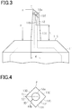
- the flow path expansion section 14b may extend in a curved shape. The configuration having the flow path expansion section 14b extending in a curved shape is shown in Fig. 3 .
- the projection 12 may have an increased contact area in the flow path expansion section 14b compared with a configuration in which the flow path expansion section 14b extends in a straight shape. Further, the above area can be finely adjusted by varying the form of the curved shape. Accordingly, a pressure of the fluid flowing in the through hole 14a when the flow path expansion section 14b starts to open can be finely set from a wide range of values, which increases the degree of freedom for the pressure setting.
- the flow path expansion section 14b is not opened compared with a configuration in which the flow path expansion section 14b extends in a straight shape in the case except for when a pressure of the fluid flowing in the through hole 14a increases, that is, a force other than that expands the through hole 14a acts on the flow path expansion section 14b.
- Fig. 4 illustrates the top face 13T of the projection 12 as viewed in a direction perpendicular to the support surface 11S of the base 11.
- the tip P of the projection 12 is located on the edge of the top face 13T, and the through hole 14a is located at the center of the top face 13T as viewed in a direction perpendicular to the support surface 11S. Further, the flow path expansion section 14b extends from the through hole 14a to one of the side surfaces 13D. This configuration is the same when the projection 12 is viewed in a direction perpendicular to the top face 13T.
- the flow path expansion section 14b is preferably included in the region S2 farther from the tip P. That is, when four side surfaces 13D of the projection 12 are divided into two side surfaces 13D close to the tip P and the two side surfaces 13D farther from the tip P, the flow path expansion section 14b is preferably disposed on the side surface 13D which is farther from tip P.
- the side surface 13D having the flow path expansion section 14b is preferably a side surface 13D which does not include the tip P, such that the side surface 13D having the flow path expansion section 14b and the top face 13T share one of the edges of the top face 13T which is located on the lower side of the slope, that is, the edge closer to the proximal end of the projection 12.
- region S1 and the region S2 may be the regions divided by the perpendicular bisector to the line segment joining the tip P and the edge of the top face 13T through the center of gravity of the top face 13T.
- the flow path expansion section 14b is preferably included in the region S2, which is farther from the tip P.
- the projection 12 With the configuration in which the projection 12 has the slant top face 13T and the tip P is located on the edge of the top face 13T, the projection 12 is pierced into the skin in administration of liquid drug by the tip P which is spaced from the through hole 14a.
- the projection does not have a sharp tip.
- the portion of the projection 12 around the through hole is first pierced into the skin.
- the former configuration that is, the configuration of the present embodiment, facilitates piercing of the projection 12 into the skin and prevents skin tissue from entering into the through hole 14a compared with the latter configuration.
- the portion of the projection 12 closer to the tip P will undergo a larger force applied by the skin when the projection 12 is pierced into the skin. Therefore, in a configuration in which the flow path expansion section 14b is disposed in the portion of the projection 12 farther from the tip P, that is, the portion which is less likely to have a force applied thereon in piercing the skin, a decrease in strength of the projection 12 in piercing the skin can be reduced among the configurations having a cut as the flow path expansion section 14b.
- the flow path expansion section 14b may be disposed at the interface between the two side surfaces 13D, that is, on the edge shared by the two side surfaces 13D.
- the flow path expansion section 14b can be fabricated more easily in a configuration in which the flow path expansion section 14b is disposed in one of the side surfaces 13D, since the distance from the through hole 14a to the peripheral surface of the projection 12 at the position where the flow path expansion section 14b is formed is smaller.
- the projection 12 can be made of any material as long as the material can form the projection 12 having the rigidity to such an extent that the flow path expansion section 14b is opened in response to an increase in pressure of the fluid flowing in the through hole 14a.
- the projection 12 may be made of metal materials such as silicon, stainless steel, titanium, cobalt-chromium alloy, magnesium alloy, and the like.
- the projection 12 may be made of resin materials such as commodity plastics, medical grade plastics, and plastics for cosmetic product.
- the resin material include polyethylene, polypropylene, polystyrene, polyamide, polycarbonate, cyclic polyolefin, polylactic acid, polyglycolic acid, polycaprolactone, acrylic, urethane resin, aromatic polyether ketone, epoxy resin, and copolymer materials of these resins.
- the base 11 may be made of, for example, a material described above as the material for the projection 12.
- the microneedle 10 may be formed as a unitary molded product having the base 11 and the projection 12 integrally formed, or a combination of the base 11 and the projection 12 which are joined to each other after they are separately formed, or a combination of a metal material and a resin material.
- the projection 12 may be made of a metal and the base 11 may be made of a resin, or vice versa.
- the separate components of the microneedle 10 can be closely joined by using a sealing agent, adhesive, gasket, O-ring, and the like, and a combination thereof as necessary.
- Examples of the production method for the microneedle 10 include machining the outer shape of the base 11 and the projection 12, followed by forming the through hole 14a and the flow path expansion section 14b.
- the base 11 and the projection 12 may be formed by injection molding when the microneedle 10 is made of a resin material.
- the flow path expansion section 14b may be formed by filling a resin in two circumferential directions toward a position where the flow path expansion section 14b is intended to be formed so that two flows of resin meet at the position in a state that the surface of the resin is cured.
- the flow path expansion section 14b may be formed by machining or the like, which is performed as a post-process of injection molding.
- the microneedle 10 when the microneedle 10 is made of two different materials, the microneedle 10 may be formed by insert molding, double-molding, or the like.
- processing method for forming the flow path expansion section 14b after the outer shape of the base 11 and the projection 12 is formed include laser processing, ultrasonic processing, and the like.
- the method for producing the microneedle 10 by integral molding using injection molding will be described as an example of the production method for the microneedle 10.
- a mold 30 for use in injection molding includes a fixed mold 31, a first movable mold 32, a second movable mold 33, and a core pin 34.
- the fixed mold 31 has a projection forming groove 31a having a shape corresponding to the shape of the projection 12.
- a portion of the fixed mold 31 in which the projection forming groove 31a is formed can be replaceable so that the shape of the projection forming groove 31a in the fixed mold 31 can be modified.
- the first movable mold 32 and the second movable mold 33 are molds which are movable relative to the fixed mold 31.
- the first movable mold 32 has a first molding groove 32a corresponding to the shape of one of the halves of the base 11 located under the tip P of the projection 12, while the second movable mold 33 has a second molding groove 33a corresponding to the other of the halves of the base 11.
- the core pin 34 includes a main body 35 and a distal portion 36.
- the main body 35 is a portion of the microneedle 10 which forms an inner peripheral surface of the base 11, and the distal portion 36 is a portion which forms the through hole 14a of the projection 12.
- a runner 37 for introducing a resin into the mold 30 is disposed on the first movable mold 32.
- a portion of the first molding groove 32a to which the runner 37 is connected is a gate 38.
- a molten resin is introduced into the mold 30 from an injection molding machine. Accordingly, a resin flows into the first molding groove 32a through the runner 37 and the gate 38, and then into the projection forming groove 31a and the second molding groove 33a.
- a flow speed of the resin introduced through the gate 38, a flow speed of the resin flowing in the mold 30, the positions and number of the gates 38, a timing when the resin is introduced through the gate 38, or the like can be adjusted so that the flows of resin, which flow in two circumferential directions toward the position where the flow path expansion section 14b is intended to be formed in the projection forming groove 31a, meet at the position in a state that the surface of the resin is cured.
- the mold 30 when in use is mounted in a mold base having a flow path for compressed air for cooling so that compressed air is supplied into the flow path during filling of the mold 30 with resin so as to partially cool the mold 30.
- a flow rate of the compressed air can be adjusted so that the mold 30 has a temperature gradient to thereby adjust the flow speed of the resin flowing in the projection forming groove 31a.
- the first movable mold 32, the second movable mold 33, and the core pin 34 are displaced to take out the microneedle 10 from the mold 30.
- the microneedle 10 is mounted on an end of the outer cylinder 41 of the syringe barrel 40.
- the microneedle 10 is pressed against the skin of target for administration of the liquid drug to thereby pierce the skin using the projection 12.
- the plunger 42 is pushed into the microneedle 10.
- a liquid drug M in the outer cylinder 41 is supplied into the base 11 of the microneedle 10, and then into the through hole 14a of the projection 12.
- the liquid drug M flows out from the opening on the top face 13T on the projection 12 and flows into the skin.
- the flow path expansion section 14b is closed. That is, a communication path that communicates between the inner space of the through hole 14a and the space surrounding the projection 12 is closed.
- skin tissue enters the through hole 14a, it clogs part of the through hole 14a.
- a pressure of the liquid drug flowing in the through hole 14a increases, a force attempting to expand the through hole 14a increases.
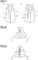
- the flow path expansion section 14b opens as shown in Fig. 7(b) .
- the projection 12 is separated at a position from the top face 13T to the side surface 13D of the projection 12 into two parts, forming a gap which communicates with the through hole 14a.
- the above-mentioned communication path is open, expanding the flow path for the liquid drug in the projection 12.
- the communication path opens to the top face 13T of the projection 12 and the side surface 13D.
- the flow path expansion section 14b is a cut extending from the top face 13T to the side surface 13D of the projection 12, that is, a cut formed at a position of the flow path expansion section 14b is opened as a communication path
- the communication path expands wider as it is closer to the top face 13T. That is, the closer to the proximal end of the projection 12, the smaller the extent of expansion of the flow path for the liquid drug. Accordingly, when the flow path expansion section 14b is open, the liquid drug supplied to the projection 12 is prevented from flowing out from the projection 12 at a position near the support surface 11S. Therefore, leakage of the liquid drug onto the skin surface can be prevented.
- an increase in diameter of the through hole 14a is possible.
- increasing the diameter of the through hole 14a involves an increase in the entire dimensions of the projection 12 in order to ensure the strength of the projection 12.
- the large sized projection 12 causes a problem of increase in resistance in piercing the projection 12 into the skin.
- the larger the diameter of the through hole 14a the larger the outlet port for a liquid drug. Accordingly, there is always a risk of leakage of liquid drug to a site other than the intended site for administration of the liquid drug, for example, into the skin or onto the skin surface, during administration of the liquid drug.
- smooth administration of the liquid drug is possible while preventing the above problems.
- a risk of leakage of liquid drug to a site other than the intended site for administration of the liquid drug increases compared with the case when the flow path expansion section 14b is closed.
- a risk of leakage of liquid drug can be minimized since the flow path expansion section 14b is closed until the pressure of liquid drug flowing in the through hole 14a becomes higher.
- the through hole 14a does not have clogging or the like and the pressure of liquid drug flowing in the through hole 14a remains low, the risk of leakage of liquid drug can remain low during administration of the liquid drug.
- the flow path expansion section 14b may be closed as in the initial state, or may remain open.
- a projection 20 may be truncated obliquely to the extending direction of the cone.
- the peripheral surface of the projection 20 is composed of a side surface 21D, which is a curved surface extending from the support surface 11S, and a top face 21T connected to the side surface 21D and inclined relative to the support surface 11S.
- the flow path expansion section 14b is preferably formed to extend from a position on the top face 21T farthest from the tip P to the side surface 21D.
- the projection is prevented from decreasing in strength even if it has the flow path expansion section 14b.
- the projection may have a prism shape or a cylindrical shape truncated obliquely to the extending direction thereof.
- Fig. 9 illustrates a projection 22 having a quadrangular prism truncated obliquely to the extending direction thereof.
- the peripheral surface of the projection 22 is composed of four side surfaces 23D extending from the support surface 11S and a top face 23T connected to the side surfaces 23D and inclined relative to the support surface 11S.
- the width W of the projection is constant from the distal end to the proximal end of the projection, and a resistance in piercing the projection into the skin can be small compared with the configuration having a varying width W.
- the projection may not necessarily have an inclined top face, and the tip of the projection may be located at the center of the projection as viewed in a direction perpendicular to the support surface 11S.
- a projection 24 shown in Fig. 10 has a cone shape which tapers toward the center through hole 14a.
- the peripheral surface of the projection 24 is composed of a side surface 25D, which is a curved surface extending from the support surface 11S, and the tip of the projection 24 is not a sharpened vertex but an open end of the through hole 14a.
- the flow path expansion section 14b extends from the through hole 14a to the peripheral surface of the projection 24, as well as extending from an open end of the through hole 14a toward the support surface 11S as viewed in a direction parallel with the support surface 11S.
- the same effects as those described in the (1), (2), (5) to (8) can be obtained.
- the configuration in which the peripheral surface of the projection is composed of side surfaces extending from the support surface 11S and a top face inclined relative to the support surface 11S, and the tip P of the projection is located on the edge of the top face is preferred due to the ease of piercing the projection into the skin and prevention of skin tissue from entering the through hole 14a.
- the projection is not limited to the shape illustrated in the above embodiment and Figs. 8 to 10 , and may be in any shape that can pierce the skin.
- the projection may have two or more different shapes in the extending direction of the projection from among a pyramid, a cone, a cylinder, and a prism.
- the projection may have a groove or a shoulder on the peripheral surface.
- the top face of the projection may be curved.
- the through hole 14a may be formed at a position deviated from the center of the projection 12 as viewed in a direction perpendicular to the support surface 11S.
- the flow path expansion section 14b is preferably formed at a position having a small distance from the through hole 14a to the peripheral surface of the projection 12.
- the flow path expansion section 14b may not be necessarily a continuous cut as long as it is configured to expand a communication path in response to an increase in pressure of the fluid flowing in the through hole 14a.
- the flow path expansion section 14b may be formed by internal reforming by laser processing, ultrasonic processing, or the like, or a plurality of processed parts formed by physical change by heat, pressure, or the like. That is, the processed parts may extend from the through hole 14a to the peripheral surface of the projection 12, and may be an array of a plurality of processed parts arranged from an open end of the through hole 14a toward the support surface 11S as viewed in a direction parallel with the support surface 11S. In this case, a cut (communication path) substantially does not exist in the flow path expansion section 14b when a fluid does not flow in the through hole 14a.
- the projection 12 splits at the flow path expansion section 14b from a processed part having a low strength in response to an increase in pressure of a fluid flowing in the through hole 14a, thereby opening a communication path.
- the flow path expansion section 14b may be a portion where flows of the material for forming the projection 12 join each other while creating an interface during fabrication, like a weld-line in resin molding, and has a lower strength than that of remaining portions. Then, the projection 12 splits at the flow path expansion section 14b having a low strength in response to an increase in pressure of a fluid flowing in the through hole 14a, thereby opening a communication path.
- the flow path expansion section 14b may be a weakened portion having a lower strength than that of the remaining portion.
- the flow path expansion section 14b may be formed as a cut before a fluid flows in the through hole 14a as described in the above embodiment, or alternatively, as a configuration that becomes a cut in response to an increase in pressure of a fluid flowing in the through hole 14a as described above.
- the flow path expansion section 14b extends from the through hole 14a to the peripheral surface of the projection, as well as extending from an open end of the through hole 14a toward the support surface 11S as viewed in a direction parallel with the support surface 11S, and if it is configured to expand a cut as a communication path formed at a position of the flow path expansion section 14b in response to an increase in pressure of a fluid flowing in the through hole 14a, the effect of the above (5) can be obtained.
- the flow path expansion section 14b in the above embodiment is closed when a fluid does not flow in the through hole 14a
- the flow path expansion section 14b may be normally open. That is, the communication path may be open when a fluid does not flow in the through hole 14a.
- the communication path is open when a fluid does not flow in the through hole 14a.
- the flow path expansion section 14c further opens to expand the communication path when a pressure of a fluid flowing in the through hole 14a becomes a predetermined pressure or more.
- the flow path expansion section may have any configuration as far as it expands a communication path in response to an increase in pressure of a fluid flowing in the through hole 14a, regardless of whether the communication path is open or closed when a fluid does not flow in the through hole 14a.
- the configuration in which communication path is closed when a fluid does not flow in the through hole 14a is more likely to reduce a risk of leakage of liquid drug to a site other than the intended site for administration of the liquid drug during a period before clogging occurs in the through hole 14a. Further, when the through hole 14a does not have clogging or the like and the pressure of liquid drug flowing in the through hole 14a remains low, a risk of leakage of liquid drug can remain low.
- an absent portion of the structure of the projection 12 can be small compared with a configuration in which the flow path expansion section 14c formed in the projection 12 is normally open as in the case of the flow path expansion section formed as a groove, the projection 12 can be prevented from decreasing in strength, and the entire dimensions of the projection 12 necessary for ensuring the strength of the projection 12 can be small.
- the flow path expansion section 14b may be configured to open when a pressure of a fluid flowing in the through hole 14a becomes a predetermined pressure or more, and maintain the opening degree, or open wider as the pressure of a fluid increases.
- the projection 12 may have a plurality of flow path expansion sections 14b.
- a plurality of flow path expansion sections 14b are preferably regularly arranged around the through hole 14a as viewed in a direction perpendicular to the support surface 11S.
- the base 11 may not be necessarily a tubular shape if the base 11 has the support surface 11S that supports the projection 12.
- usage of the microneedle 10 is not limited to being mounted on the syringe barrel 40.
- a liquid drug may be supplied into the through hole 14a of the projection 12 by using a tool other than the syringe barrel 40. Further, the projection 12 may be separated from the base 11 after administration of the liquid drug and left in the skin of the administration target.
- microneedle will be described below by using specific examples and comparative examples.
- a mold base having a mold mounted therein was provided.
- the mold included a fixed mold, a first movable mold, a second movable mold, and a core pin.
- a projection molding groove of the fixed mold was formed to produce a projection in a quadrangular pyramid shape truncated obliquely to the extending direction thereof as shown in Fig. 1 , having a length of the projection of 0.8 mm.
- a first molding groove of the first movable mold and a second molding groove of the second movable mold are formed to produce a circular support surface.
- a distal end of the core pin had a cylindrical shape with a diameter of 100 ⁇ m.
- the mold base had a flow path for compression air for cooling, ensuring partial cooling of the fixed mold.
- the above mold was mounted in a full automatic injection molding machine (SE18DU, manufactured by Sumitomo Heavy Industries, Ltd.). Polycarbonate heated at 290°C was injected into the mold at an injection speed of 50 mm/sec, followed by cooling of the mold for a period of 10 seconds.
- injection of resin the amount of compressed air supplied into the flow path in the mold base was adjusted so that a temperature gradient was generated in the fixed mold to thereby control the speed of resin flowing around the distal end of the core pin in the projection molding groove. Molding was performed after the resin used was dried at 120°C for a period of 8 hours. After the resin was cured, a molded product was taken out from the mold, and then a runner was removed to thereby obtain a microneedle of the example.
- an area of an opening formed by the through hole on the top face of the projection when the flow path expansion section 14b was closed was 7.9 ⁇ 10 -3 mm 2 .
- Molding was performed under the same conditions as the above example except that the temperature of the fixed mold was made uniform without supplying compressed air into the flow path in the mold base during injection of resin. Thus, a microneedle of the comparative example was obtained. In microscopic observation of the microneedle of the comparative example, it was found that a cut was not formed in the microneedle.
- microneedles of the example and comparative example were used to evaluate injection pressure.
- a microneedle was mounted on a syringe barrel, which was filled with saline as a liquid drug, and the projection was then pierced into skin taken from a 12-week-old Wistar rat, followed by injection of 50 ⁇ L of saline into the projection. A maximum pressure required for the injection was measured.
- a tube to which a pressure gauge was connected was inserted into the outer cylinder of the syringe barrel. Then, a gas was supplied into the tube until an inside pressure of the tube reaches a predetermined value. The gas pressure was increased in 0.01 Mpa increments until the injection of saline was completed. Thus, a maximum injection pressure was measured.
- maximum injection pressures in a plurality of samples were measured.
- the average of maximum injection pressures in the microneedle of the comparative example was 0.12 Mpa.
- the average of maximum injection pressures in the microneedle of the example was 0.08 Mpa. That is, it was found that the microneedle of the example allowed for administration of liquid drug at an injection pressure lower than the microneedle of the comparative example, had a through hole which was not susceptible to clogging, and ensured smooth administration of a liquid drug.
Landscapes
- Health & Medical Sciences (AREA)
- Engineering & Computer Science (AREA)
- Dermatology (AREA)
- Medical Informatics (AREA)
- Anesthesiology (AREA)
- Biomedical Technology (AREA)
- Heart & Thoracic Surgery (AREA)
- Hematology (AREA)
- Life Sciences & Earth Sciences (AREA)
- Animal Behavior & Ethology (AREA)
- General Health & Medical Sciences (AREA)
- Public Health (AREA)
- Veterinary Medicine (AREA)
- Media Introduction/Drainage Providing Device (AREA)
Claims (7)
- Eine Mikronadel (10), die Folgendes aufweist:eine Basis (11) mit einer Stützfläche (11S); undeinen Vorsprung (12; 20; 22; 24), der von der Stützfläche (11S) vorsteht, wobei der Vorsprung (12; 20; 22; 24) ein Durchgangsloch (14a) aufweist, das den Vorsprung (12; 20; 22; 24) in einer Erstreckungsrichtung des Vorsprungs (12; 20; 22; 24) durchdringt, wobeider Vorsprung (12; 20; 22; 24) einen Strömungswegausdehnungsabschnitt (14b; 14c) aufweist, der so konfiguriert ist, dass er einen Verbindungsweg ausdehnt, der zwischen einem Innenraum des Durchgangslochs (14a) und einem den Vorsprung (12; 20; 22; 24) umgebenden Raum als Reaktion auf einen Druckanstieg eines in dem Durchgangsloch (14a) strömenden Fluids verbindet,
dadurch gekennzeichnet, dass
das Durchgangsloch (14a) ein offenes Ende hat, das an einem distalen Ende des Vorsprungs (12; 20; 22; 24) offen ist, und
der Strömungswegausdehnungsabschnitt (14b; 14c) ein linearer Abschnitt ist, der sich von dem Durchgangsloch (14a) zu der Umfangsfläche des Vorsprungs (12; 20; 22; 24) erstreckt und sich von dem offenen Ende des Durchgangslochs (14a) in Richtung der Stützfläche (11S), in einer Richtung parallel zu der Stützfläche (11S) gesehen, erstreckt und so konfiguriert ist, dass er einen Schnitt, der an einer Position des Strömungswegausdehnungsabschnitts (14b; 14c) als der Verbindungsweg ausgebildet ist, als Reaktion auf einen Druckanstieg des in dem Durchgangsloch (14a) strömenden Fluids ausdehnt. - Mikronadel (10) nach Anspruch 1, wobei der Verbindungsweg geschlossen ist, wenn kein Fluid in dem Durchgangsloch (14a) strömt.
- Die Mikronadel (10) nach Anspruch 1 oder 2, wobei
eine Umfangsfläche des Vorsprungs (12; 20; 22; 24) Seitenflächen (13D; 21D; 23D; 25D), die sich von der Stützfläche (11S) aus erstrecken, und eine obere Fläche (13T; 21T; 23T) aufweist, die mit den Seitenflächen (13D; 21D; 23D; 25D) verbunden ist, wobei die obere Fläche (13T; 21T; 23T) relativ zur Stützfläche (11S) geneigt ist,
das Durchgangsloch (14a) an der oberen Fläche offen ist (13T; 21T; 23T), und
eine Spitze des Vorsprungs (12; 20; 22; 24) an einer Kante der oberen Fläche (13T; 21T; 23T), gesehen in einer Richtung senkrecht zur Auflagefläche (11S), angeordnet ist. - Mikronadel (10) nach Anspruch 3, wobei, unter der Annahme, dass die obere Fläche (13T; 21T; 23T) in einen Bereich näher an der Spitze des Vorsprungs (12; 20; 22; 24) und einen Bereich weiter weg von der Spitze des Vorsprungs (12; 20; 22; 24), gesehen in einer Richtung senkrecht zur Stützfläche (11S), unterteilt ist, der Verbindungsweg in dem Bereich weiter weg von der Spitze angeordnet ist.
- Mikronadel (10) nach Anspruch 1, wobei ein Ende des Strömungswegausdehnungsabschnitts (14b; 14c) von der Stützfläche (11S), in einer Richtung parallel zur Stützfläche (11S) gesehen, beabstandet ist.
- Die Mikronadel (10) nach einem der Ansprüche 1 bis 5, wobei ein Druck des Fluids, wenn der Strömungswegausdehnungsabschnitt (14b; 14c) beginnt, den Verbindungsweg auszudehnen, 0,20 MPa oder weniger beträgt.
- Die Mikronadel (10) nach einem der Ansprüche 1 bis 6, wobei ein Bereich einer Öffnung, die durch das Durchgangsloch (14a) auf der Umfangsfläche des Vorsprungs (12; 20; 22; 24) gebildet wird, wenn ein Fluid nicht in das Durchgangsloch (14a) strömt, in einem Bereich von 5,0 x 10⁻⁴ mm2 oder mehr und 2,0 x 10⁻¹ mm2 oder weniger liegt.
Applications Claiming Priority (2)
| Application Number | Priority Date | Filing Date | Title |
|---|---|---|---|
| JP2016019727 | 2016-02-04 | ||
| PCT/JP2017/001815 WO2017135060A1 (ja) | 2016-02-04 | 2017-01-19 | マイクロニードル |
Publications (3)
| Publication Number | Publication Date |
|---|---|
| EP3412331A1 EP3412331A1 (de) | 2018-12-12 |
| EP3412331A4 EP3412331A4 (de) | 2019-02-13 |
| EP3412331B1 true EP3412331B1 (de) | 2020-04-29 |
Family
ID=59500636
Family Applications (1)
| Application Number | Title | Priority Date | Filing Date |
|---|---|---|---|
| EP17747219.8A Not-in-force EP3412331B1 (de) | 2016-02-04 | 2017-01-19 | Mikronadel |
Country Status (4)
| Country | Link |
|---|---|
| US (1) | US10857338B2 (de) |
| EP (1) | EP3412331B1 (de) |
| JP (1) | JP6794998B2 (de) |
| WO (1) | WO2017135060A1 (de) |
Families Citing this family (7)
| Publication number | Priority date | Publication date | Assignee | Title |
|---|---|---|---|---|
| CN111148826A (zh) * | 2017-09-29 | 2020-05-12 | 凸版印刷株式会社 | 细胞移植装置以及细胞移植用单元 |
| JP7230377B2 (ja) * | 2018-09-05 | 2023-03-01 | 凸版印刷株式会社 | マイクロニードル |
| CN110711312B (zh) * | 2019-11-07 | 2021-07-30 | 河南大学 | 基于微机电系统的强促渗透皮释药微系统及其制造方法 |
| TWI889752B (zh) * | 2020-02-11 | 2025-07-11 | 瑞典商艾瑟莉恩公司 | 用於收集流體的微針和流體通道系統 |
| USD1028236S1 (en) * | 2021-10-19 | 2024-05-21 | Nanopass Technologies Ltd. | Round needle head |
| CN219090826U (zh) * | 2022-07-18 | 2023-05-30 | 深圳陪你数字科技有限公司 | 微针、微针阵列及注射装置 |
| WO2024197125A1 (en) * | 2023-03-21 | 2024-09-26 | Trustees Of Tufts College | Grooved microneedles for passive and active drug delivery |
Family Cites Families (10)
| Publication number | Priority date | Publication date | Assignee | Title |
|---|---|---|---|---|
| WO2003022330A2 (en) * | 2001-09-12 | 2003-03-20 | Becton, Dickinson And Company | Microneedle-based pen device for drug delivery and method for using same |
| JP2005021677A (ja) | 2003-06-10 | 2005-01-27 | Medorekkusu:Kk | 経皮投薬用パッドベース、及び注射針 |
| JP2007501071A (ja) * | 2003-08-04 | 2007-01-25 | アルザ・コーポレーシヨン | 経皮作用剤流率を向上させる方法および装置 |
| WO2008020632A1 (en) * | 2006-08-18 | 2008-02-21 | Toppan Printing Co., Ltd. | Microneedle and microneedle patch |
| US20090093775A1 (en) * | 2007-10-03 | 2009-04-09 | Raju Remesh S O Govinda | Microstructures |
| US20110125101A1 (en) * | 2008-07-15 | 2011-05-26 | Yoshitoshi Koyama | Otologic syringe needle |
| WO2011093674A2 (ko) * | 2010-01-29 | 2011-08-04 | (주)유바이오메드 | 마이크로 니들 및 마이크로 니들장치 |
| KR102219636B1 (ko) * | 2012-12-27 | 2021-02-23 | 쓰리엠 이노베이티브 프로퍼티즈 컴파니 | 중공형 마이크로니들을 갖는 물품 및 제조 방법 |
| JP6347960B2 (ja) * | 2014-01-29 | 2018-06-27 | Asti株式会社 | マイクロニードルユニットと注射装置 |
| JP6147230B2 (ja) * | 2014-07-03 | 2017-06-14 | Asti株式会社 | マイクロニードルアレイとマイクロニードルアレイ製造方法 |
-
2017
- 2017-01-19 JP JP2017565474A patent/JP6794998B2/ja active Active
- 2017-01-19 WO PCT/JP2017/001815 patent/WO2017135060A1/ja not_active Ceased
- 2017-01-19 EP EP17747219.8A patent/EP3412331B1/de not_active Not-in-force
- 2017-01-19 US US16/003,459 patent/US10857338B2/en not_active Expired - Fee Related
Non-Patent Citations (1)
| Title |
|---|
| None * |
Also Published As
| Publication number | Publication date |
|---|---|
| JPWO2017135060A1 (ja) | 2018-12-06 |
| US20190022364A1 (en) | 2019-01-24 |
| WO2017135060A1 (ja) | 2017-08-10 |
| EP3412331A1 (de) | 2018-12-12 |
| US10857338B2 (en) | 2020-12-08 |
| EP3412331A4 (de) | 2019-02-13 |
| JP6794998B2 (ja) | 2020-12-02 |
Similar Documents
| Publication | Publication Date | Title |
|---|---|---|
| EP3412331B1 (de) | Mikronadel | |
| JP6766802B2 (ja) | マイクロニードル | |
| JP6831386B2 (ja) | デッドスペースを減少させた流体送達用医療機器 | |
| EP1490145B1 (de) | Vorrichtung zur intradermaler verabreichung von substanzen | |
| EP3247449B1 (de) | Mikronadelanordnung | |
| CN107735143B (zh) | 微细突起器具及其制造方法 | |
| US20050177117A1 (en) | Needle with lateral aperture | |
| AU2022200875B2 (en) | Microneedle assembly | |
| US20190381256A1 (en) | Transdermal administration device | |
| KR20080058633A (ko) | 마이크로니들 어레이와 그의 성형 몰드 및 방법 | |
| US11213483B2 (en) | Implantable solid dosage form | |
| JP7230377B2 (ja) | マイクロニードル | |
| WO2014077677A1 (en) | Micro needle for transporting fluid across or into a biological barrier and method for producing such a micro needle | |
| JP7326980B2 (ja) | マイクロニードル | |
| WO2006132602A1 (en) | Polymeric microneedle array and apparatus and method for manufacturing of the same | |
| KR100707658B1 (ko) | 미세바늘 사출성형용 금형장치 | |
| JP6524812B2 (ja) | マイクロニードル、マイクロニードルの製造方法、および、マイクロニードルの使用方法 | |
| EP4674590A1 (de) | Harzformprodukt mit durchgangsloch, formverfahren dafür, form und nadellose spritze mit dem harzformprodukt | |
| CN212679844U (zh) | 一种微针产品的模具结构 | |
| TW200402314A (en) | Jet injector and method for its operation and production | |
| JP2018171330A (ja) | マイクロニードル |
Legal Events
| Date | Code | Title | Description |
|---|---|---|---|
| STAA | Information on the status of an ep patent application or granted ep patent |
Free format text: STATUS: THE INTERNATIONAL PUBLICATION HAS BEEN MADE |
|
| PUAI | Public reference made under article 153(3) epc to a published international application that has entered the european phase |
Free format text: ORIGINAL CODE: 0009012 |
|
| STAA | Information on the status of an ep patent application or granted ep patent |
Free format text: STATUS: REQUEST FOR EXAMINATION WAS MADE |
|
| 17P | Request for examination filed |
Effective date: 20180613 |
|
| AK | Designated contracting states |
Kind code of ref document: A1 Designated state(s): AL AT BE BG CH CY CZ DE DK EE ES FI FR GB GR HR HU IE IS IT LI LT LU LV MC MK MT NL NO PL PT RO RS SE SI SK SM TR |
|
| AX | Request for extension of the european patent |
Extension state: BA ME |
|
| A4 | Supplementary search report drawn up and despatched |
Effective date: 20190116 |
|
| RIC1 | Information provided on ipc code assigned before grant |
Ipc: A61M 37/00 20060101AFI20190110BHEP |
|
| DAV | Request for validation of the european patent (deleted) | ||
| DAX | Request for extension of the european patent (deleted) | ||
| GRAJ | Information related to disapproval of communication of intention to grant by the applicant or resumption of examination proceedings by the epo deleted |
Free format text: ORIGINAL CODE: EPIDOSDIGR1 |
|
| GRAP | Despatch of communication of intention to grant a patent |
Free format text: ORIGINAL CODE: EPIDOSNIGR1 |
|
| GRAP | Despatch of communication of intention to grant a patent |
Free format text: ORIGINAL CODE: EPIDOSNIGR1 |
|
| STAA | Information on the status of an ep patent application or granted ep patent |
Free format text: STATUS: GRANT OF PATENT IS INTENDED |
|
| GRAJ | Information related to disapproval of communication of intention to grant by the applicant or resumption of examination proceedings by the epo deleted |
Free format text: ORIGINAL CODE: EPIDOSDIGR1 |
|
| STAA | Information on the status of an ep patent application or granted ep patent |
Free format text: STATUS: REQUEST FOR EXAMINATION WAS MADE |
|
| GRAP | Despatch of communication of intention to grant a patent |
Free format text: ORIGINAL CODE: EPIDOSNIGR1 |
|
| STAA | Information on the status of an ep patent application or granted ep patent |
Free format text: STATUS: GRANT OF PATENT IS INTENDED |
|
| INTG | Intention to grant announced |
Effective date: 20191111 |
|
| INTG | Intention to grant announced |
Effective date: 20191121 |
|
| RIC1 | Information provided on ipc code assigned before grant |
Ipc: A61M 37/00 20060101AFI20191108BHEP |
|
| INTC | Intention to grant announced (deleted) | ||
| INTG | Intention to grant announced |
Effective date: 20191202 |
|
| GRAS | Grant fee paid |
Free format text: ORIGINAL CODE: EPIDOSNIGR3 |
|
| GRAA | (expected) grant |
Free format text: ORIGINAL CODE: 0009210 |
|
| STAA | Information on the status of an ep patent application or granted ep patent |
Free format text: STATUS: THE PATENT HAS BEEN GRANTED |
|
| AK | Designated contracting states |
Kind code of ref document: B1 Designated state(s): AL AT BE BG CH CY CZ DE DK EE ES FI FR GB GR HR HU IE IS IT LI LT LU LV MC MK MT NL NO PL PT RO RS SE SI SK SM TR |
|
| REG | Reference to a national code |
Ref country code: GB Ref legal event code: FG4D |
|
| REG | Reference to a national code |
Ref country code: CH Ref legal event code: EP |
|
| REG | Reference to a national code |
Ref country code: DE Ref legal event code: R096 Ref document number: 602017015790 Country of ref document: DE |
|
| REG | Reference to a national code |
Ref country code: AT Ref legal event code: REF Ref document number: 1262381 Country of ref document: AT Kind code of ref document: T Effective date: 20200515 |
|
| REG | Reference to a national code |
Ref country code: IE Ref legal event code: FG4D |
|
| REG | Reference to a national code |
Ref country code: NL Ref legal event code: MP Effective date: 20200429 |
|
| REG | Reference to a national code |
Ref country code: LT Ref legal event code: MG4D |
|
| PG25 | Lapsed in a contracting state [announced via postgrant information from national office to epo] |
Ref country code: LT Free format text: LAPSE BECAUSE OF FAILURE TO SUBMIT A TRANSLATION OF THE DESCRIPTION OR TO PAY THE FEE WITHIN THE PRESCRIBED TIME-LIMIT Effective date: 20200429 Ref country code: NO Free format text: LAPSE BECAUSE OF FAILURE TO SUBMIT A TRANSLATION OF THE DESCRIPTION OR TO PAY THE FEE WITHIN THE PRESCRIBED TIME-LIMIT Effective date: 20200729 Ref country code: FI Free format text: LAPSE BECAUSE OF FAILURE TO SUBMIT A TRANSLATION OF THE DESCRIPTION OR TO PAY THE FEE WITHIN THE PRESCRIBED TIME-LIMIT Effective date: 20200429 Ref country code: IS Free format text: LAPSE BECAUSE OF FAILURE TO SUBMIT A TRANSLATION OF THE DESCRIPTION OR TO PAY THE FEE WITHIN THE PRESCRIBED TIME-LIMIT Effective date: 20200829 Ref country code: PT Free format text: LAPSE BECAUSE OF FAILURE TO SUBMIT A TRANSLATION OF THE DESCRIPTION OR TO PAY THE FEE WITHIN THE PRESCRIBED TIME-LIMIT Effective date: 20200831 Ref country code: GR Free format text: LAPSE BECAUSE OF FAILURE TO SUBMIT A TRANSLATION OF THE DESCRIPTION OR TO PAY THE FEE WITHIN THE PRESCRIBED TIME-LIMIT Effective date: 20200730 Ref country code: SE Free format text: LAPSE BECAUSE OF FAILURE TO SUBMIT A TRANSLATION OF THE DESCRIPTION OR TO PAY THE FEE WITHIN THE PRESCRIBED TIME-LIMIT Effective date: 20200429 |
|
| REG | Reference to a national code |
Ref country code: AT Ref legal event code: MK05 Ref document number: 1262381 Country of ref document: AT Kind code of ref document: T Effective date: 20200429 |
|
| PG25 | Lapsed in a contracting state [announced via postgrant information from national office to epo] |
Ref country code: HR Free format text: LAPSE BECAUSE OF FAILURE TO SUBMIT A TRANSLATION OF THE DESCRIPTION OR TO PAY THE FEE WITHIN THE PRESCRIBED TIME-LIMIT Effective date: 20200429 Ref country code: RS Free format text: LAPSE BECAUSE OF FAILURE TO SUBMIT A TRANSLATION OF THE DESCRIPTION OR TO PAY THE FEE WITHIN THE PRESCRIBED TIME-LIMIT Effective date: 20200429 Ref country code: BG Free format text: LAPSE BECAUSE OF FAILURE TO SUBMIT A TRANSLATION OF THE DESCRIPTION OR TO PAY THE FEE WITHIN THE PRESCRIBED TIME-LIMIT Effective date: 20200729 Ref country code: LV Free format text: LAPSE BECAUSE OF FAILURE TO SUBMIT A TRANSLATION OF THE DESCRIPTION OR TO PAY THE FEE WITHIN THE PRESCRIBED TIME-LIMIT Effective date: 20200429 |
|
| PG25 | Lapsed in a contracting state [announced via postgrant information from national office to epo] |
Ref country code: AL Free format text: LAPSE BECAUSE OF FAILURE TO SUBMIT A TRANSLATION OF THE DESCRIPTION OR TO PAY THE FEE WITHIN THE PRESCRIBED TIME-LIMIT Effective date: 20200429 Ref country code: NL Free format text: LAPSE BECAUSE OF FAILURE TO SUBMIT A TRANSLATION OF THE DESCRIPTION OR TO PAY THE FEE WITHIN THE PRESCRIBED TIME-LIMIT Effective date: 20200429 |
|
| PG25 | Lapsed in a contracting state [announced via postgrant information from national office to epo] |
Ref country code: CZ Free format text: LAPSE BECAUSE OF FAILURE TO SUBMIT A TRANSLATION OF THE DESCRIPTION OR TO PAY THE FEE WITHIN THE PRESCRIBED TIME-LIMIT Effective date: 20200429 Ref country code: ES Free format text: LAPSE BECAUSE OF FAILURE TO SUBMIT A TRANSLATION OF THE DESCRIPTION OR TO PAY THE FEE WITHIN THE PRESCRIBED TIME-LIMIT Effective date: 20200429 Ref country code: DK Free format text: LAPSE BECAUSE OF FAILURE TO SUBMIT A TRANSLATION OF THE DESCRIPTION OR TO PAY THE FEE WITHIN THE PRESCRIBED TIME-LIMIT Effective date: 20200429 Ref country code: IT Free format text: LAPSE BECAUSE OF FAILURE TO SUBMIT A TRANSLATION OF THE DESCRIPTION OR TO PAY THE FEE WITHIN THE PRESCRIBED TIME-LIMIT Effective date: 20200429 Ref country code: SM Free format text: LAPSE BECAUSE OF FAILURE TO SUBMIT A TRANSLATION OF THE DESCRIPTION OR TO PAY THE FEE WITHIN THE PRESCRIBED TIME-LIMIT Effective date: 20200429 Ref country code: AT Free format text: LAPSE BECAUSE OF FAILURE TO SUBMIT A TRANSLATION OF THE DESCRIPTION OR TO PAY THE FEE WITHIN THE PRESCRIBED TIME-LIMIT Effective date: 20200429 Ref country code: EE Free format text: LAPSE BECAUSE OF FAILURE TO SUBMIT A TRANSLATION OF THE DESCRIPTION OR TO PAY THE FEE WITHIN THE PRESCRIBED TIME-LIMIT Effective date: 20200429 Ref country code: RO Free format text: LAPSE BECAUSE OF FAILURE TO SUBMIT A TRANSLATION OF THE DESCRIPTION OR TO PAY THE FEE WITHIN THE PRESCRIBED TIME-LIMIT Effective date: 20200429 |
|
| REG | Reference to a national code |
Ref country code: DE Ref legal event code: R097 Ref document number: 602017015790 Country of ref document: DE |
|
| PG25 | Lapsed in a contracting state [announced via postgrant information from national office to epo] |
Ref country code: PL Free format text: LAPSE BECAUSE OF FAILURE TO SUBMIT A TRANSLATION OF THE DESCRIPTION OR TO PAY THE FEE WITHIN THE PRESCRIBED TIME-LIMIT Effective date: 20200429 Ref country code: SK Free format text: LAPSE BECAUSE OF FAILURE TO SUBMIT A TRANSLATION OF THE DESCRIPTION OR TO PAY THE FEE WITHIN THE PRESCRIBED TIME-LIMIT Effective date: 20200429 |
|
| PLBE | No opposition filed within time limit |
Free format text: ORIGINAL CODE: 0009261 |
|
| STAA | Information on the status of an ep patent application or granted ep patent |
Free format text: STATUS: NO OPPOSITION FILED WITHIN TIME LIMIT |
|
| 26N | No opposition filed |
Effective date: 20210201 |
|
| PG25 | Lapsed in a contracting state [announced via postgrant information from national office to epo] |
Ref country code: SI Free format text: LAPSE BECAUSE OF FAILURE TO SUBMIT A TRANSLATION OF THE DESCRIPTION OR TO PAY THE FEE WITHIN THE PRESCRIBED TIME-LIMIT Effective date: 20200429 |
|
| PG25 | Lapsed in a contracting state [announced via postgrant information from national office to epo] |
Ref country code: MC Free format text: LAPSE BECAUSE OF FAILURE TO SUBMIT A TRANSLATION OF THE DESCRIPTION OR TO PAY THE FEE WITHIN THE PRESCRIBED TIME-LIMIT Effective date: 20200429 |
|
| REG | Reference to a national code |
Ref country code: CH Ref legal event code: PL |
|
| PG25 | Lapsed in a contracting state [announced via postgrant information from national office to epo] |
Ref country code: LU Free format text: LAPSE BECAUSE OF NON-PAYMENT OF DUE FEES Effective date: 20210119 |
|
| REG | Reference to a national code |
Ref country code: BE Ref legal event code: MM Effective date: 20210131 |
|
| PG25 | Lapsed in a contracting state [announced via postgrant information from national office to epo] |
Ref country code: LI Free format text: LAPSE BECAUSE OF NON-PAYMENT OF DUE FEES Effective date: 20210131 Ref country code: CH Free format text: LAPSE BECAUSE OF NON-PAYMENT OF DUE FEES Effective date: 20210131 |
|
| PG25 | Lapsed in a contracting state [announced via postgrant information from national office to epo] |
Ref country code: IE Free format text: LAPSE BECAUSE OF NON-PAYMENT OF DUE FEES Effective date: 20210119 |
|
| PG25 | Lapsed in a contracting state [announced via postgrant information from national office to epo] |
Ref country code: BE Free format text: LAPSE BECAUSE OF NON-PAYMENT OF DUE FEES Effective date: 20210131 |
|
| PGFP | Annual fee paid to national office [announced via postgrant information from national office to epo] |
Ref country code: GB Payment date: 20221201 Year of fee payment: 7 Ref country code: FR Payment date: 20221208 Year of fee payment: 7 |
|
| PGFP | Annual fee paid to national office [announced via postgrant information from national office to epo] |
Ref country code: DE Payment date: 20221130 Year of fee payment: 7 |
|
| PG25 | Lapsed in a contracting state [announced via postgrant information from national office to epo] |
Ref country code: CY Free format text: LAPSE BECAUSE OF FAILURE TO SUBMIT A TRANSLATION OF THE DESCRIPTION OR TO PAY THE FEE WITHIN THE PRESCRIBED TIME-LIMIT Effective date: 20200429 |
|
| P01 | Opt-out of the competence of the unified patent court (upc) registered |
Effective date: 20230530 |
|
| PG25 | Lapsed in a contracting state [announced via postgrant information from national office to epo] |
Ref country code: HU Free format text: LAPSE BECAUSE OF FAILURE TO SUBMIT A TRANSLATION OF THE DESCRIPTION OR TO PAY THE FEE WITHIN THE PRESCRIBED TIME-LIMIT; INVALID AB INITIO Effective date: 20170119 |
|
| PG25 | Lapsed in a contracting state [announced via postgrant information from national office to epo] |
Ref country code: MK Free format text: LAPSE BECAUSE OF FAILURE TO SUBMIT A TRANSLATION OF THE DESCRIPTION OR TO PAY THE FEE WITHIN THE PRESCRIBED TIME-LIMIT Effective date: 20200429 |
|
| REG | Reference to a national code |
Ref country code: DE Ref legal event code: R119 Ref document number: 602017015790 Country of ref document: DE |
|
| GBPC | Gb: european patent ceased through non-payment of renewal fee |
Effective date: 20240119 |
|
| PG25 | Lapsed in a contracting state [announced via postgrant information from national office to epo] |
Ref country code: MT Free format text: LAPSE BECAUSE OF FAILURE TO SUBMIT A TRANSLATION OF THE DESCRIPTION OR TO PAY THE FEE WITHIN THE PRESCRIBED TIME-LIMIT Effective date: 20200429 |
|
| PG25 | Lapsed in a contracting state [announced via postgrant information from national office to epo] |
Ref country code: DE Free format text: LAPSE BECAUSE OF NON-PAYMENT OF DUE FEES Effective date: 20240801 |
|
| PG25 | Lapsed in a contracting state [announced via postgrant information from national office to epo] |
Ref country code: GB Free format text: LAPSE BECAUSE OF NON-PAYMENT OF DUE FEES Effective date: 20240119 |
|
| PG25 | Lapsed in a contracting state [announced via postgrant information from national office to epo] |
Ref country code: FR Free format text: LAPSE BECAUSE OF NON-PAYMENT OF DUE FEES Effective date: 20240131 |
|
| PG25 | Lapsed in a contracting state [announced via postgrant information from national office to epo] |
Ref country code: GB Free format text: LAPSE BECAUSE OF NON-PAYMENT OF DUE FEES Effective date: 20240119 Ref country code: FR Free format text: LAPSE BECAUSE OF NON-PAYMENT OF DUE FEES Effective date: 20240131 Ref country code: DE Free format text: LAPSE BECAUSE OF NON-PAYMENT OF DUE FEES Effective date: 20240801 |
|
| PG25 | Lapsed in a contracting state [announced via postgrant information from national office to epo] |
Ref country code: TR Free format text: LAPSE BECAUSE OF FAILURE TO SUBMIT A TRANSLATION OF THE DESCRIPTION OR TO PAY THE FEE WITHIN THE PRESCRIBED TIME-LIMIT Effective date: 20200429 |