EP3408536B1 - Kolbenkompressor mit entlüftungseinrichtung - Google Patents
Kolbenkompressor mit entlüftungseinrichtung Download PDFInfo
- Publication number
- EP3408536B1 EP3408536B1 EP17701320.8A EP17701320A EP3408536B1 EP 3408536 B1 EP3408536 B1 EP 3408536B1 EP 17701320 A EP17701320 A EP 17701320A EP 3408536 B1 EP3408536 B1 EP 3408536B1
- Authority
- EP
- European Patent Office
- Prior art keywords
- valve
- compression chamber
- piston compressor
- pressure
- inlet
- Prior art date
- Legal status (The legal status is an assumption and is not a legal conclusion. Google has not performed a legal analysis and makes no representation as to the accuracy of the status listed.)
- Active
Links
Images

Classifications
-
- F—MECHANICAL ENGINEERING; LIGHTING; HEATING; WEAPONS; BLASTING
- F04—POSITIVE - DISPLACEMENT MACHINES FOR LIQUIDS; PUMPS FOR LIQUIDS OR ELASTIC FLUIDS
- F04B—POSITIVE-DISPLACEMENT MACHINES FOR LIQUIDS; PUMPS
- F04B49/00—Control, e.g. of pump delivery, or pump pressure of, or safety measures for, machines, pumps, or pumping installations, not otherwise provided for, or of interest apart from, groups F04B1/00 - F04B47/00
- F04B49/16—Control, e.g. of pump delivery, or pump pressure of, or safety measures for, machines, pumps, or pumping installations, not otherwise provided for, or of interest apart from, groups F04B1/00 - F04B47/00 by adjusting the capacity of dead spaces of working chambers
-
- F—MECHANICAL ENGINEERING; LIGHTING; HEATING; WEAPONS; BLASTING
- F04—POSITIVE - DISPLACEMENT MACHINES FOR LIQUIDS; PUMPS FOR LIQUIDS OR ELASTIC FLUIDS
- F04B—POSITIVE-DISPLACEMENT MACHINES FOR LIQUIDS; PUMPS
- F04B35/00—Piston pumps specially adapted for elastic fluids and characterised by the driving means to their working members, or by combination with, or adaptation to, specific driving engines or motors, not otherwise provided for
- F04B35/04—Piston pumps specially adapted for elastic fluids and characterised by the driving means to their working members, or by combination with, or adaptation to, specific driving engines or motors, not otherwise provided for the means being electric
-
- F—MECHANICAL ENGINEERING; LIGHTING; HEATING; WEAPONS; BLASTING
- F04—POSITIVE - DISPLACEMENT MACHINES FOR LIQUIDS; PUMPS FOR LIQUIDS OR ELASTIC FLUIDS
- F04B—POSITIVE-DISPLACEMENT MACHINES FOR LIQUIDS; PUMPS
- F04B35/00—Piston pumps specially adapted for elastic fluids and characterised by the driving means to their working members, or by combination with, or adaptation to, specific driving engines or motors, not otherwise provided for
- F04B35/002—Piston pumps specially adapted for elastic fluids and characterised by the driving means to their working members, or by combination with, or adaptation to, specific driving engines or motors, not otherwise provided for driven by internal combustion engines
-
- F—MECHANICAL ENGINEERING; LIGHTING; HEATING; WEAPONS; BLASTING
- F04—POSITIVE - DISPLACEMENT MACHINES FOR LIQUIDS; PUMPS FOR LIQUIDS OR ELASTIC FLUIDS
- F04B—POSITIVE-DISPLACEMENT MACHINES FOR LIQUIDS; PUMPS
- F04B39/00—Component parts, details, or accessories, of pumps or pumping systems specially adapted for elastic fluids, not otherwise provided for in, or of interest apart from, groups F04B25/00 - F04B37/00
- F04B39/08—Actuation of distribution members
-
- F—MECHANICAL ENGINEERING; LIGHTING; HEATING; WEAPONS; BLASTING
- F04—POSITIVE - DISPLACEMENT MACHINES FOR LIQUIDS; PUMPS FOR LIQUIDS OR ELASTIC FLUIDS
- F04B—POSITIVE-DISPLACEMENT MACHINES FOR LIQUIDS; PUMPS
- F04B39/00—Component parts, details, or accessories, of pumps or pumping systems specially adapted for elastic fluids, not otherwise provided for in, or of interest apart from, groups F04B25/00 - F04B37/00
- F04B39/12—Casings; Cylinders; Cylinder heads; Fluid connections
- F04B39/125—Cylinder heads
-
- F—MECHANICAL ENGINEERING; LIGHTING; HEATING; WEAPONS; BLASTING
- F04—POSITIVE - DISPLACEMENT MACHINES FOR LIQUIDS; PUMPS FOR LIQUIDS OR ELASTIC FLUIDS
- F04B—POSITIVE-DISPLACEMENT MACHINES FOR LIQUIDS; PUMPS
- F04B49/00—Control, e.g. of pump delivery, or pump pressure of, or safety measures for, machines, pumps, or pumping installations, not otherwise provided for, or of interest apart from, groups F04B1/00 - F04B47/00
- F04B49/02—Stopping, starting, unloading or idling control
- F04B49/022—Stopping, starting, unloading or idling control by means of pressure
Definitions
- the invention relates to a piston compressor for compressing a gas, which can optionally be separated from a drive device by means of a coupling, with an inlet valve which is arranged between an inlet line for gas to be compressed and a compression chamber of the piston compressor and an outlet valve which is arranged between the compression chamber of the piston compressor and a compressed gas discharge line is arranged.
- Such compressors are used, for example, for supplying compressed air to commercial vehicles, in particular for supplying compressed air to the brake system.
- the compressor is driven by the drive train of the internal combustion engine.
- Applications are known in which a coupling is arranged between the compressor and the drive connection in order to separate the compressor from the drive when the compressed air system of the commercial vehicle is filled with compressed air.
- the outlet line of the compressor is emptied simultaneously with the opening of the clutch. When the compressor is restarted, the pressure in the then pressure-free outlet line must first be built up again before compressed air can be supplied to the compressed air system.
- solutions are also known in which the outlet line is not switched to a pressure-free state while the piston compressor is not driven.
- a piston compressor which can be disconnected from the drive via a clutch when a certain maximum pressure has been built up.
- the clutch is disengaged, i.e. the drive is disconnected from the piston compressor, by means of a pressure from the compressed air reservoir filled by the piston compressor during operation.
- the piston compressor When the piston compressor is restarted with such a high pressure in the compression chamber, the first compression stroke of the piston results in a compression of the gas in the compression chamber to about 60 bar.
- the torque that occurs here is far too high for the clutch, which in this case slips, overheats and wears impermissibly.
- such a high pressure in the compression chamber can also damage the compressor itself.
- the pamphlets DE30 42 069 A1 and DE 20 2006 020 240 U1 each disclose a technical teaching which is suitable for eliminating such a problem and for venting the compression chamber during the time in which the piston is not driven by the drive.
- the two publications each specify options for venting the pressure on the outlet side of the compressor, for which either a complicated mechanical design ( DE 30 42 069 A1 ) or a complex electrical solution ( DE 20 2006 020 240 U1 ) is applied.
- the invention is therefore based on the object of providing an improved reciprocating compressor which avoids the aforementioned disadvantages and the undesirable effects arising therefrom.
- a piston compressor for compressing a gas which can be separated from a drive device, with an inlet valve which is arranged between an inlet line for the gas to be compressed and a compression chamber of the piston compressor and an outlet valve which is arranged between the compression chamber of the piston compressor and an outlet line for compressed gas is arranged.
- the piston compressor has a venting device, through which compressed gas can be discharged from the compression chamber, which gas passes back into the compression chamber from the outlet line during the separation of the piston compressor from the drive device.
- Such a reciprocating compressor has an inlet line which is in particular part of an inlet system and through which a gas to be compressed is guided to a compression chamber of the reciprocating compressor.
- An inlet valve is arranged between the inlet line and the compression chamber, which is open while gas to be compressed is being sucked into the compression chamber (the pressure in the compression chamber is lower than the pressure in the inlet line).
- the inlet valve closes the compression space off from the inlet line.
- An outlet valve is arranged between the compression space and the outlet line, which is opened when the compressed gas is expelled from the compression space (the pressure in the compression space is higher than the pressure in the outlet line) and thus defines a connection between the compression space and the outlet line.
- the outlet valve closes the connection between the compression space and the outlet line while the gas to be compressed is being sucked into the compression space (the pressure in the compression space is lower than the pressure in the outlet line) in order to prevent the backflow of compressed gas from the outlet line into the compression space.
- valves with a closing body are often used which, depending on the pressure difference on both sides of the valve, is pressed onto the valve seat and thereby closes or is lifted from the valve seat, whereby the valve opens.
- a common type of valve of this type has a valve tongue serving as a closing body.
- the piston compressor according to the invention has a venting device, through which compressed gas can be discharged from the compression chamber in order to lower the pressure therein.
- compressed gas can be discharged, which during a separation of the piston compressor from the drive device, in particular through an exhaust valve that does not close completely, gets back into the compression chamber from the pressurized outlet line and causes a pressure increase there.
- the compressed gas can be discharged from the compression chamber into an area with lower pressure, in particular ambient pressure, by means of the ventilation device. This allows the compressed gas to enter an area escape, which has a lower pressure than the compression chamber into which compressed gas has penetrated from the outlet line. As a result of the discharge of the compressed gas, the pressure in the compression chamber drops.
- the area with the ambient pressure is formed by the environment itself, a gas space connected to the inlet system or the inlet line, or the interior of the crankcase of the reciprocating compressor.
- An area with ambient pressure in the intake system can be, for example, the intake line or a gas space connected to it, which is formed, for example, in the cylinder head of the piston compressor and thus also represents part of the intake line.
- the area with the ambient pressure is formed by the interior of the crankcase of the piston compressor
- the gas flowing through the ventilation device from the compression chamber of the piston compressor is guided into the crankcase, where in particular a pressure equalization in the crankcase and then via its ventilation system with the environment takes place.
- Pressure fluctuations can occur both in a gas space connected to the intake system and in the crankcase of the reciprocating compressor: in the intake system, in particular, depending on the fresh gas intake - for example when the intake system is connected to the intake system of a correspondingly large internal combustion engine - or in particular due to previous crank drive movements in the crankcase .
- the pressure prevailing in a gas space connected to the intake system or in the crankcase is regarded as ambient pressure in connection with this invention .
- the inlet valve forms the venting device.
- the inlet valve is designed so that a connection between the inlet line and the compression chamber can only be closed from a pressure in the compression chamber that is at least 0.1 bar, preferably at least 0.2 bar and in particular at least 0.5 bar higher than that Pressure in the inlet line, which essentially corresponds to the ambient pressure.
- a pressure in the compression chamber which is below the limit value of at least 0.1 bar, preferably at least 0.2 bar and in particular at least 0.5 bar excess pressure, there is a continuous connection between the Inlet pipe and the compression chamber.
- a compressed gas that enters the compression chamber during a separation of the piston compressor from the drive device, i.e. when the piston compressor is at a standstill, can be discharged through this opening of the inlet valve into the inlet line without pressure build-up in the compression chamber of the compressor.
- the inlet valve in which the inlet valve can only be closed from a predetermined pressure in the compression chamber, has a concave valve seat, in particular on the valve plate, and an essentially flat valve tongue, so that the valve tongue can only be opened after a pressure
- the elastic deformation caused in the compression chamber is in sealing contact with the valve seat.
- the inlet valve only closes when a sufficiently high pressure acts in the compression chamber during the compression stroke, which pressure deforms the valve tongue in such a way that it rests against the concave valve seat in a sealing manner.
- the inlet valve is open. Thus, no pressure build-up can be brought about in the compression chamber by compressed gas which returns from the outlet line to the compression chamber during the separation of the piston compressor from the drive device.
- the inlet valve in which the inlet valve can only be closed from a predetermined pressure in the compression chamber, has a flat valve seat and a curved valve tongue.
- the valve tongue consequently only lies against the valve seat in a sealing manner after an elastic deformation caused by the pressure in the compression chamber.
- the inlet valve only closes when a sufficiently high pressure acts in the compression chamber during a compression stroke, which deforms the bent valve tongue in such a way that it rests sealingly on the valve seat that is just formed.
- the inlet valve remains open as long as the pressure in the compression chamber has a lower value than the pressure which leads to the inlet valve closing, in particular during a compression stroke.
- a compressed gas which returns from the outlet line to the compression chamber during the separation of the piston compressor from the drive device cannot lead to a pressure build-up in the compression chamber.
- a ventilation channel forms the ventilation device.
- a ventilation channel which in particular creates a permanent connection to an area with a lower pressure than the compression chamber, in particular ambient pressure, allows gas to flow from one end of the ventilation channel in the compression chamber, which is under a higher pressure, through the ventilation channel into an area with a lower pressure Pressure, in particular ambient pressure, can be dissipated at the other end of the ventilation duct. This results in a pressure equalization with the compression chamber. So if gas from the pressurized outlet line returns to the compression chamber during a separation of the piston compressor from the drive device, no increased pressure can build up there because the gas is discharged through the ventilation duct.
- At least one end of the ventilation duct is arranged in the valve plate and in particular establishes a connection between the compression chamber and the surroundings of the reciprocating compressor or its inlet system.
- a disadvantage of a permanently open ventilation duct is that it allows the gas to escape from the compression chamber even during a compression stroke, which reduces the efficiency of the compressor.
- the vent channel has such a small cross section that pressure equalization through the vent channel is possible, but the throttling effect of the small cross section of the vent channel prevents the pressure flow of a larger volume flow during a compression stroke.
- An alternative design which restricts the gas from escaping from the compression chamber during a compression stroke, has a suitable shut-off valve in the venting channel, which closes it once a predetermined excess pressure has been reached.
- a check valve suitable for this is, for example, a gravity ball valve.
- Such a shut-off valve is advantageously designed to be robust against contamination by lubricating oil impurities.
- At least one end of the ventilation duct is arranged in the cylinder wall, which for example establishes a connection with the surroundings of the piston compressor.
- the ventilation channel can have a connecting device in the form of a line, which serves as an extension of the ventilation channel and this in particular with or with the inlet system connects to the interior of the crankcase of the reciprocating compressor.
- a ventilation duct also forms an opening in the compression chamber through which gas can escape from the compression chamber even during the compression stroke, which reduces the efficiency of the piston compressor.
- the ventilation duct is therefore designed to be large enough to ensure pressure equalization so that the gas volume flow, which can thereby be removed from the compression chamber during a separation of the compressor from the drive device, is at least as large as that from the outlet line back in this time segment The gas volume flow of compressed gas from the outlet line reached the compression chamber.
- a check valve or a check valve is arranged in the ventilation channel or in a connecting device connected to it.
- a check or shut-off valve can on the one hand prevent gas from escaping from the compression chamber during a compression stroke of the reciprocating compressor, on the other hand such a check or shut-off valve can also serve to prevent possibly contaminated gas, especially from the crankcase, from being sucked into the compression chamber.
- piston, cylinder, cylinder head, etc. is addressed above in connection with the components of the piston compressor, the properties described here also apply to a piston compressor with two or more of these elements, since the present invention is not only for single-stage piston compressors but can also be used for multi-stage piston compressors.
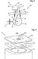
- Fig. 1 shows a schematic representation of an exemplary reciprocating compressor 10 as it is known as the prior art.
- the crankshaft 11 of the piston compressor 10 is connected to a drive device (not shown, here an internal combustion engine) via a clutch 3 and can optionally be separated from this drive device by means of the clutch 3.
- a drive device not shown, here an internal combustion engine
- the clutch 3 When the clutch 3 is disengaged, no torque is transmitted to the crankshaft 11 of the piston compressor 10, so that the crankshaft 11 stands still during the separation of the piston compressor 10 from the drive device.
- the crankshaft 11 is connected to a connecting rod 12 eccentrically mounted thereon, on which a piston 13 is mounted.
- the piston 13 is mounted so that it can move axially in a cylinder 14 of the piston compressor 10.
- the crank drive 15, which has at least one crankshaft 11, a connecting rod 12 and a piston 13, is arranged in a crankcase 16 which is fixedly connected to the cylinder 14.
- the piston 13 is moved by the connecting rod 12 in the cylinder 14 in such a way that it executes a stroke movement.
- the cylinder 14 is closed by a valve plate 20.
- the cylinder 14, the piston 13 and the valve plate 20 thus define the compression chamber 17 in the cylinder 14.
- the inlet line 22 is part of an inlet system 23 which sucks in fresh air from the environment through a filter (not shown) and supplies it to the compression chamber 17 via the inlet line 22 through the cylinder head (not shown).
- the cylinder head is arranged above the valve plate 20 and has a cylinder head volume 24, which over the Inlet valve 21 is in communication with the compression chamber 17.
- the inlet valve 21 is designed as a shut-off valve, which enables fresh air to be sucked into the compression chamber 17, but prevents the air drawn in via the inlet line 22 from flowing back into the compression chamber 17.
- FIG. 11 shows an illustration of an exemplary discharge valve 26 as is frequently used in reciprocating compressors 10 in the prior art.
- the outlet valve 26 is arranged on the valve plate 20 of the reciprocating compressor 10 above the compression chamber 17.
- the valve plate 20 has an outlet opening 28 which connects the compression chamber 17 to a cylinder head volume 27a which is arranged in the valve plate 20 and cylinder head of the piston compressor 10 and which forms part of the outlet line 27.
- the outlet valve 26 has a valve tongue 26a as the valve body, which is released from the valve seat 26b from a predetermined pressure difference between the compression chamber 17 and the outlet line 27 and enables air to flow from the compression chamber 17 into the outlet line 27.
- the outlet valve 26 also has a contact element 26c which is arranged above the outlet opening 28 and on which the valve tongue 26a rests in the open state. As soon as the valve tongue 26a detaches from the valve seat 26b, the pressurized air can flow from the compression chamber 17 through the lateral open areas past the valve tongue 26a and the contact element 26c into the outlet line 27.
- the valve plate 20 or the cylinder head volume 27a can, for example, have a pressure of up to 6 bar applied to it by the air flowing back there.
- the piston compressor 10 If the piston compressor 10 is then reconnected to the drive device, the piston compressor 10 generates an internal pressure of approximately 60 bar on the first stroke. If the compression chamber 17 can withstand this enormous internal pressure, the torque generated on the crankshaft 11 is usually much too high for the clutch 3, so that the clutch 3 slips, overheats and wears impermissibly quickly.
- FIG. 3 shows a schematic representation of a fourth exemplary embodiment of a reciprocating compressor 10 according to the invention.
- the structure of the reciprocating compressor 10 in FIG Fig. 3 largely corresponds to the structure of the in Fig. 1 piston compressor 10 illustrated and described for this purpose, so that the same elements of the piston compressors 10 are denoted by the same reference numerals. Only the differences of the reciprocating compressor 10 are discussed below Fig. 3 compared to the piston compressor 10 Fig. 1 explained.
- the in Fig. 3 The piston compressor 10 shown has a ventilation device in the form of a ventilation duct 34 which is arranged between the compression chamber 17 and the inlet system 23.
- the ventilation channel 34 establishes a connection through which air can flow between the compression chamber 17 and the inlet system 23, so that when the piston compressor is at a standstill, no pressure can build up in the compression chamber 17 that is significantly higher than the ambient pressure.
- the vent channel 34 is arranged in the area of the valve plate 20 on the upper side of the cylinder 14, so that a constant pressure equalization with the inlet line 32 of the piston compressor 10 takes place through the vent channel 34. If compressed air reaches the compression chamber 17 from the outlet line 27 while the piston compressor 10 is at a standstill, pressure equalization with the inlet line 22 takes place through the ventilation duct 34, so that no pressure build-up can occur in the compression chamber 17.
- a disadvantage of such a ventilation duct 34 is that it is also open during a compression stroke of the piston compressor 10 and air to be compressed escapes from the compression chamber 17 in this phase. This lowers the efficiency of the reciprocating compressor 10.
- vent channel 34 is therefore like this designed that this has only a small cross-section to enable sufficient pressure equalization while the piston compressor 10 is at a standstill with the inlet system 23, but on the other hand has a throttling effect at high pressures in order to limit the volume flow of the discharged air.
- FIG. 4 shows a representation of a detail of a ninth exemplary embodiment of a piston compressor 10 according to the invention, in which the inlet valve 21 forms the venting device.
- the elements of the inlet valve 21 are shown in FIG Fig. 4 shown in exploded view.
- the inlet valve 21 forms the upper end of the compression chamber 17 in the cylinder 14.
- the valve tongue 21a is designed in one piece with a first element of the inlet valve 21, which is arranged between the cylinder 14 and a contact element 21b of the inlet valve 21.
- the contact element 21b shown as an example has two valve openings 21c which are closed by the valve tongue 21a depending on the pressure difference between the compression chamber 17 in the cylinder 14 and the pressure in the inlet system 23.
- the valve tongue 21a has a curvature which is designed in such a way that the valve tongue 21a rests against the contact element 21b from a pressure in the compression chamber 22 (dashed representation of the valve tongue 21a) which in the exemplary embodiment is 0.4 bar higher than the pressure in the inlet system 23 ( Ambient pressure) and thereby closes the valve openings 21c.
- the valve tongue 21a always has a curvature that there is a connection between the inlet system 23 and the compression chamber 17.
- a compressed gas that has entered the compression chamber 17 can be discharged through the valve openings 21c of the inlet valve 21 into the inlet line 22 without a pressure build-up in the compression chamber 17 of the compressor 10.
- FIG. 5 shows a schematic representation of a further exemplary embodiment of a piston compressor 10 according to the invention.
- the structure of the piston compressor 10 in FIG. 5 largely corresponds to the structure of the piston compressor 10 in FIG Fig. 3 piston compressor 10 illustrated and described for this purpose, so that identical elements of the piston compressors 10 are denoted by the same reference numerals. In the following, only the differences between the piston compressor 10 from FIG. 5 and the piston compressor 10 will be discussed Fig. 3 explained.
- a piston compressor 10 which also has a venting device in the form of a venting channel 39, which runs between the compression space 17 and the inlet system 23 is arranged.
- a check valve in the form of a gravity ball valve 40 is arranged in the vent duct 39, which closes the vent duct 39 when the pressure in the compression chamber 17 exceeds a predetermined value, which presses the ball of the gravity ball valve 40 against its gravity on a valve seat located at the top of the gravity ball valve 40.
- the shut-off valve thus restricts the escape of compressed air from the compression chamber 17 during a compression stroke.
- the inlet valve 21 can also have a contact element 21b which has a recess in the area of the valve openings 21c, so that the valve tongue 21a in this embodiment as well only from a predetermined pressure in Compression chamber 17 rests sealingly on contact element 21b.
Landscapes
- Engineering & Computer Science (AREA)
- Mechanical Engineering (AREA)
- General Engineering & Computer Science (AREA)
- Chemical & Material Sciences (AREA)
- Combustion & Propulsion (AREA)
- Compressor (AREA)
- Applications Or Details Of Rotary Compressors (AREA)
Description
- Die Erfindung betrifft einen Kolbenkompressor zum Verdichten eines Gases, der optional mittels einer Kupplung von einer Antriebseinrichtung trennbar ist, mit einem Einlassventil, welches zwischen einer Einlassleitung für zu verdichtendes Gas und einem Verdichtungsraum des Kolbenkompressors angeordnet ist und einem Auslassventil, welches zwischen dem Verdichtungsraum des Kolbenkompressors und einer Auslassleitung für verdichtetes Gas angeordnet ist.
- Derartige Kompressoren werden beispielsweise für die Druckluftversorgung von Nutzfahrzeugen, insbesondere für die Druckluftversorgung des Bremssystems eingesetzt. Dabei erfolgt der Antrieb des Kompressors über den Antriebsstrang des Verbrennungsmotors. Es sind Anwendungen bekannt, bei welchen zwischen dem Kompressor und der Antriebsverbindung eine Kupplung angeordnet ist, um den Kompressor vom Antrieb zu trennen, wenn das Druckluftsystem des Nutzfahrzeugs mit Druckluft gefüllt ist. Bei bekannten Ausführungsformen wird gleichzeitig mit dem Öffnen der Kupplung die Auslassleitung des Kompressors entleert. Bei der Wiederinbetriebnahme des Kompressors muss erst der Druck in der dann druckfreien Auslassleitung wieder aufgebaut werden, bevor Druckluft in das Druckluftsystem geliefert werden kann. Zur Vermeidung solcher Effizienzverluste sind auch Lösungen bekannt, bei welchen die Auslassleitung nicht druckfrei geschaltet wird, während der Kolbenkompressor nicht angetrieben wird.
- In der
EP 0 122 015 A1 ist ein Kolbenkompressor offenbart der, über eine Kupplung vom Antrieb getrennt werden kann, wenn ein bestimmter Maximaldruck aufgebaut wurde. Das Ausrücken der Kupplung, also die Trennung des Antriebs vom Kolbenkompressor, geschieht dabei mittels eines Drucks aus dem vom Kolbenkompressor während des Betriebs gefüllten Druckluftspeicher. - Bei Kolbenkompressoren der genannten Art besteht die Gefahr, dass ein Auslassventil durch Verunreinigen wie Beläge durch Schmierölrückstände oder insbesondere von solchen gelöste Partikel undicht wird. Dabei weisen die Auslassventile häufig eine Ventilzunge auf, zwischen die und deren Ventilsitz solche Verunreinigungen gelangen können und dort das vollständige Schließen des Ventils verhindern. Im Fall einer beispielsweise hieraus resultierenden Undichtigkeit eines Auslassventils in Verbindung mit einer unter Druck stehenden Auslassleitung während der Trennung des Kompressors vom Antrieb kann Druckluft zurück in den Verdichtungsraum des Kompressors gelangen. Der Druck im Verdichtungsraum eines Kolbenkompressors in einem 12,5 bar-System kann dann auf bis zu 6 bar ansteigen. Bei der Wiederinbetriebnahme des Kolbenkompressors mit einem derart hohen Druck im Verdichtungsraum resultiert beim ersten Verdichtungshub des Kolbens eine Verdichtung des Gases im Verdichtungsraum auf etwa 60 bar. Das hierbei auftretende Drehmoment ist bei weitem zu hoch für die Kupplung, welche in diesem Fall durchrutscht, überhitzt und unzulässig stark verschleißt. Zudem kann ein solch hoher Druck im Verdichtungsraum auch zu einer Beschädigung des Kompressors selbst führen.
- Die Druckschriften
DE30 42 069 A1 undDE 20 2006 020 240 U1 offenbaren jeweils eine technische Lehre, die dazu geeignet ist ein solches Problem zu beheben und den Verdichtungsraum, während der Zeit in der der Kolben nicht vom Antrieb angetrieben ist, zu entlüften. Dazu werden in den beiden Druckschriften jeweils Möglichkeiten genannt, den Druck auf der Auslassseite des Kompressors zu entlüften, wozu entweder eine komplizierte mechanische Konstruktion (DE 30 42 069 A1 ) oder eine aufwendige elektrische Lösung (DE 20 2006 020 240 U1 ) angewendet wird. - Der Erfindung liegt daher die Aufgabe zugrunde, einen verbesserten Kolbenkompressor zur Verfügung zu stellen, welcher die vorgenannten Nachteile und die hieraus entstehenden unerwünschten Wirkungen vermeidet.
- Zur Lösung dieser Aufgabe wird ein Kolbenkompressor gemäß Anspruch 1 vorgeschlagen. Weiterbildungen des Kolbenkompressors sind Gegenstand der abhängigen Ansprüche.
- Zur Lösung der Aufgabe wird ein Kolbenkompressor zum Verdichten eines Gases vorgeschlagen, der von einer Antriebseinrichtung trennbar ist, mit einem Einlassventil, welches zwischen einer Einlassleitung für zu verdichtendes Gas und einem Verdichtungsraum des Kolbenkompressors angeordnet ist und einem Auslassventil, welches zwischen dem Verdichtungsraum des Kolbenkompressors und einer Auslassleitung für verdichtetes Gas angeordnet ist. Der Kolbenkompressor weist eine Entlüftungseinrichtung auf, durch welche verdichtetes Gas aus dem Verdichtungsraum abführbar ist, das während der Trennung des Kolbenkompressors von der Antriebseinrichtung aus der Auslassleitung zurück in den Verdichtungsraum gelangt.
- Ein solcher Kolbenkompressor weist eine Einlassleitung auf, die insbesondere Teil eines Einlasssystems ist und durch welche ein zu verdichtendes Gas zu einem Verdichtungsraum des Kolbenkompressors geführt wird. Zwischen der Einlassleitung und dem Verdichtungsraum ist dabei ein Einlassventil angeordnet, welches während dem Ansaugen von zu verdichtendem Gas in den Verdichtungsraum (der Druck im Verdichtungsraum ist geringer als der Druck in der Einlassleitung) geöffnet ist. Während der Verdichtung des Gases im Verdichtungsraum (der Druck im Verdichtungsraum ist höher als der Druck in der Einlassleitung) schließt das Einlassventil den Verdichtungsraum gegenüber der Einlassleitung ab.
- Zwischen dem Verdichtungsraum und der Auslassleitung ist ein Auslassventil angeordnet, welches beim Ausstoßen des verdichteten Gases aus dem Verdichtungsraum geöffnet ist (der Druck im Verdichtungsraum ist höher als der Druck in der Auslassleitung) und so eine Verbindung zwischen dem Verdichtungsraum und der Auslassleitung definiert. Das Auslassventil schließt während dem Ansaugen von zu verdichtendem Gas in den Verdichtungsraum die Verbindung zwischen Verdichtungsraum und Auslassleitung ab (der Druck im Verdichtungsraum ist geringer als der Druck in der Auslassleitung), um ein Rückströmen von verdichtetem Gas aus der Auslassleitung in den Verdichtungsraum zu verhindern.
- Sowohl für Einlass- als auch für Auslassventile von Kolbenkompressoren werden häufig Ventile mit einem Schließkörper eingesetzt, der abhängig von der Druckdifferenz auf beiden Seiten des Ventils auf den Ventilsitz gedrückt wird und dadurch schließt oder vom Ventilsitz abgehoben wird, wodurch das Ventil öffnet. Eine übliche Bauart solcher Ventile weist eine als Schließkörper dienende Ventilzunge auf.
- Der erfindungsgemäße Kolbenkompressor weist eine Entlüftungseinrichtung auf, durch welche verdichtetes Gas aus dem Verdichtungsraum abführbar ist, um den Druck darin zu senken. Dabei ist insbesondere verdichtetes Gas abführbar, welches während einer Trennung des Kolbenkompressors von der Antriebseinrichtung insbesondere durch ein nicht vollständig schließendes Auslassventil aus der unter Druck stehenden Auslassleitung zurück in den Verdichtungsraum gelangt und dort eine Druckerhöhung verursacht.
- Bei einer Ausführungsform des Kolbenkompressors ist das verdichtete Gas mittels der Entlüftungseinrichtung aus dem Verdichtungsraum in einen Bereich mit geringerem Druck, insbesondere Umgebungsdruck abführbar. Damit kann das verdichtete Gas in einen Bereich entweichen, der einen gegenüber dem Verdichtungsraum, in welchen verdichtetes Gas aus der Auslassleitung eingedrungen ist, einen geringeren Druck aufweist. Infolge des Abführens des verdichteten Gases sinkt der Druck im Verdichtungsraum.
- Bei einer Ausführungsform des Kolbenkompressors wird der Bereich mit dem Umgebungsdruck von der Umgebung selbst, einem mit dem Einlasssystem bzw. der Einlassleitung verbundenen Gasraum oder dem Inneren des Kurbelgehäuses des Kolbenkompressors gebildet. Ein Bereich mit Umgebungsdruck im Einlasssystem kann beispielsweise die Einlassleitung oder ein mit dieser verbundener Gasraum sein, der beispielsweise im Zylinderkopf des Kolbenkompressors ausgebildet ist und damit auch einen Teil der Einlassleitung darstellt. Bei einer Ausführungsform, bei welcher der Bereich mit dem Umgebungsdruck vom Innenraum des Kurbelgehäuses des Kolbenkompressors gebildet ist, wird das durch die Entlüftungseinrichtung aus dem Verdichtungsraum des Kolbenkompressors strömende Gas in das Kurbelgehäuse geführt, wo insbesondere zunächst ein Druckausgleich im Kurbelgehäuse und sodann über dessen Entlüftungssystem mit der Umgebung stattfindet.
- Dabei können sowohl in einem mit dem Einlasssystem verbundenen Gasraum als auch im Kurbelgehäuse des Kolbenkompressors Druckschwankungen auftreten: im Einlasssystem insbesondere abhängig von der Frischgasansaugung - beispielsweise wenn das Einlasssystem in Verbindung mit dem Einlasssystem eines entsprechend groß dimensionierten Verbrennungsmotors steht - oder aufgrund insbesondere vorangegangener Kurbeltriebsbewegungen im Kurbelgehäuse. Da jedoch sowohl das Einlasssystem als auch das Kurbelgehäuse mit der Umgebung in Verbindung stehen und dort üblicherweise ein ständiger Ausgleich von Druckschwankungen mit der Umgebung erfolgt, wird der in einem mit dem Einlasssystem verbundenen Gasraum oder im Kurbelgehäuse herrschende Druck im Zusammenhang mit dieser Erfindung als Umgebungsdruck betrachtet.
- Bei einer weiteren Ausführungsform bildet das Einlassventil die Entlüftungseinrichtung. Das Einlassventil ist dabei so ausgebildet, dass damit eine Verbindung zwischen der Einlassleitung und dem Verdichtungsraum erst ab einem Druck im Verdichtungsraum verschließbar ist, der wenigstens 0,1 bar, bevorzugt wenigstens 0,2 bar und insbesondere wenigstens 0,5 bar höher ist als der Druck in der Einlassleitung, der im Wesentlichen dem Umgebungsdruck entspricht. Dabei besteht bei einem Druck im Verdichtungsraum, der unter dem Grenzwert von wenigstens 0,1 bar, bevorzugt wenigstens 0,2 bar und insbesondere wenigstens 0,5 bar Überdruck liegt, eine fortwährende Verbindung zwischen der Einlassleitung und dem Verdichtungsraum. So ist ein verdichtetes Gas, das während einer Trennung des Kolbenkompressors von der Antriebseinrichtung, also im Stillstand des Kolbenkompressors, in den Verdichtungsraum gelangt, durch diese Öffnung des Einlassventils in die Einlassleitung abführbar, ohne dass ein Druckaufbau im Verdichtungsraum des Kompressors erfolgt.
- Bei einer Ausführungsform des Kolbenkompressors, bei welcher das Einlassventil erst ab einem vorbestimmten Druck im Verdichtungsraum verschließbar ist, weist das Einlassventil einen konkav ausgebildeten Ventilsitz insbesondere an der Ventilplatte und eine im Wesentlichen eben ausgebildete Ventilzunge auf, so dass die Ventilzunge erst nach einer durch einen Druck im Verdichtungsraum bewirkten elastischen Verformung dichtend an dem Ventilsitz anliegt. Bei einer derartigen Ausführungsform schließt das Einlassventil erst, wenn während des Verdichtungshubs ein ausreichend hoher Druck im Verdichtungsraum wirkt, welcher die Ventilzunge derart verformt, dass diese dichtend an dem konkav ausgebildeten Ventilsitz anliegt. Solange der Druck im Verdichtungsraum einen niedrigeren Wert aufweist als der Druck, der zum Schließen des Einlassventils führt, ist das Einlassventil geöffnet. So kann durch verdichtetes Gas, das während der Trennung des Kolbenkompressors von der Antriebseinrichtung aus der Auslassleitung zurück in den Verdichtungsraum gelangt, kein Druckaufbau im Verdichtungsraum bewirkt werden.
- Bei einer anderen Ausführungsform des Kolbenkompressors, bei welcher das Einlassventil erst ab einem vorbestimmten Druck im Verdichtungsraum verschließbar ist, weist das Einlassventil einen eben ausgebildeten Ventilsitz und eine gebogen ausgebildete Ventilzunge auf. Die Ventilzunge liegt folglich erst nach einer durch den Druck im Verdichtungsraum bewirkten elastischen Verformung dichtend an dem Ventilsitz an. Auch bei dieser Ausführungsform schließt das Einlassventil erst, wenn während eines Verdichtungshubs ein ausreichend hoher Druck im Verdichtungsraum wirkt, welcher die gebogen ausgeführte Ventilzunge derart verformt, dass diese dichtend an dem eben ausgebildeten Ventilsitz anliegt. Auch hier bleibt das Einlassventil geöffnet, solange der Druck im Verdichtungsraum einen geringeren Wert aufweist als der Druck, der insbesondere während eines Verdichtungshubs zum Schließen des Einlassventils führt. So kann auch bei dieser Ausführungsform ein verdichtetes Gas, das während der Trennung des Kolbenkompressors von der Antriebseinrichtung aus der Auslassleitung zurück in den Verdichtungsraum gelangt, zu keinem Druckaufbau im Verdichtungsraum führen.
- Bei einer anderen Ausführungsform des Kolbenkompressors bildet ein Entlüftungskanal die Entlüftungseinrichtung. Durch einen solchen Entlüftungskanal, der insbesondere eine permanente Verbindung zu einem Bereich mit einem gegenüber dem Verdichtungsraum geringeren Druck, insbesondere Umgebungsdruck herstellt, kann Gas von einem Ende des Entlüftungskanals im Verdichtungsraum, der unter einem höheren Druck steht, durch den Entlüftungskanal in einen Bereich mit geringerem Druck, insbesondere Umgebungsdruck am anderen Ende des Entlüftungskanals abgeführt werden. Dadurch findet ein Druckausgleich mit dem Verdichtungsraum statt. Sofern also während einer Trennung des Kolbenkompressors von der Antriebseinrichtung Gas aus der unter Druck stehenden Auslassleitung zurück in den Verdichtungsraum gelangt, kann sich dort kein erhöhter Druck aufbauen, da das Gas durch den Entlüftungskanal abgeführt wird.
- Bei einer Ausführungsform ist wenigstens ein Ende des Entlüftungskanals in der Ventilplatte angeordnet und stellt insbesondere eine Verbindung des Verdichtungsraums zur Umgebung des Kolbenkompressors oder zu dessen Einlasssystem her. Nachteilig an einem permanent geöffneten Entlüftungskanal ist, dass dieser auch während eines Verdichtungshubs ein Entweichen des Gases aus dem Verdichtungsraum ermöglicht, wodurch sich die Effizienz des Kompressors verringert. Bei einer Ausführungsform weist der Entlüftungskanal allerdings einen so geringen Querschnitt auf, dass ein Druckausgleich durch den Entlüftungskanal möglich ist, die Drosselwirkung des geringen Querschnitts des Entlüftungskanals jedoch den Druckfluss eines größeren Volumenstroms während eines Verdichtungshubs verhindert.
- Eine alternative Gestaltung, welche ein Entweichen des Gases aus dem Verdichtungsraum während eines Verdichtungshubs einschränkt weist ein geeignetes Sperrventil im Entlüftungskanal auf, welches diesen ab einem vorbestimmten Überdruck schließt. Ein hierfür geeignetes Sperrventil ist beispielsweise ein Schwerkraftkugelventil. Vorteilhafterweise ist ein solches Sperrventil robust gegen eine Verschmutzung durch Schmierölverunreinigungen ausgeführt.
- Bei einer anderen Ausführungsform ist wenigstens ein Ende des Entlüftungskanals in der Zylinderwandung angeordnet, der beispielsweise eine Verbindung mit der Umgebung des Kolbenkompressors herstellt. Ausgehend von der Außenseite der Zylinderwandung kann der Entlüftungskanal eine Verbindungseinrichtung in Form einer Leitung aufweisen, welche als Verlängerung des Entlüftungskanals dient und diesen insbesondere mit dem Einlasssystem oder mit dem Innenraum des Kurbelgehäuses des Kolbenkompressors verbindet. Auch ein solcher Entlüftungskanal bildet eine Öffnung im Verdichtungsraum, durch welche auch während des Verdichtungshubs Gas aus dem Verdichtungsraum entweichen kann, womit die Effizienz des Kolbenverdichters sinkt. Der Entlüftungskanal ist daher insbesondere groß genug ausgelegt, um einen Druckausgleich zu gewährleisten, damit Gasvolumenstrom, der hierdurch während einer Trennung des Kompressors von der Antriebseinrichtung aus dem Verdichtungsraum abgeführt werden kann, mindestens so groß ist, wie der in diesem Zeitabschnitt aus der Auslassleitung zurück in den Verdichtungsraum gelangte Gasvolumenstrom von verdichtetem Gas aus der Auslassleitung.
- Bei einer Ausführungsform des Kolbenkompressors ist im Entlüftungskanal bzw. in einer damit verbundenen Verbindungseinrichtung ein Rückschlagventil oder ein Sperrventil angeordnet. Ein solches Rückschlag- oder Sperrventil kann einerseits ein Entweichen von Gas während eines Verdichtungshubs des Kolbenkompressors aus dem Verdichtungsraum vermeiden, andererseits kann ein solches Rückschlag- oder Sperrventil auch dazu dienen, ein Ansaugen von möglicherweise verunreinigtem Gas insbesondere aus dem Kurbelgehäuse in den Verdichtungsraum verhindern.
- Obwohl vorausgehend im Zusammenhang mit den Bauteilen des Kolbenkompressors jeweils der Kolben, der Zylinder, der Zylinderkopf usw. adressiert ist, treffen die hierzu beschriebenen Eigenschaften jeweils auch auf einen Kolbenkompressor mit zwei oder mehr dieser Elemente zu, da die vorliegende Erfindung nicht nur für einstufige Kolbenkompressoren sondern auch für mehrstufige Kolbenkompressoren Verwendung finden kann.
- Weitere Vorteile, Merkmale und Anwendungsmöglichkeiten der vorliegenden Erfindung ergeben sich aus der nachfolgenden Beschreibung im Zusammenhang mit den Figuren.
- In den Figuren zeigen:
- Fig. 1
- eine schematische Darstellung eines beispielhaften Kolbenkompressors des Stands der Technik;
- Fig. 2
- eine Darstellung eines beispielhaften Auslassventils wie es in Kolbenkompressoren im Stand der Technik verwendet wird;
- Fig. 3
- eine schematische Darstellung einer vierten beispielhaften Ausführungsform eines erfindungsgemäßen Kolbenkompressors, bei welcher die Entlüftungseinrichtung einen Entlüftungskanal aufweist;
- Fig. 4
- eine Darstellung eines Details einer neunten beispielhaften Ausführungsform eines erfindungsgemäßen Kolbenkompressors, bei welchem das Einlassventil die Entlüftungseinrichtung bildet.
- Fig. 5
- eine schematische Darstellung einer weiteren beispielhaften Ausführungsform eines erfindungsgemäßen Kolbenkompressors, bei welcher die Entlüftungseinrichtung einen Entlüftungskanal mit Sperrventil aufweist;
-
Fig. 1 zeigt eine schematische Darstellung eines beispielhaften Kolbenkompressors 10 wie er als Stand der Technik bekannt ist. Die Kurbelwelle 11 des Kolbenkompressors 10 ist über eine Kupplung 3 mit einer Antriebseinrichtung (nicht dargestellt, hier ein Verbrennungsmotor) verbunden und mittels der Kupplung 3 wahlweise von dieser Antriebseinrichtung trennbar. Bei geöffneter Kupplung 3 wird somit kein Drehmoment auf die Kurbelwelle 11 des Kolbenkompressors 10 übertragen, so dass die Kurbelwelle 11 während der Trennung des Kolbenkompressors 10 von der Antriebseinrichtung still steht. - Die Kurbelwelle 11 ist mit einem exzentrisch daran gelagerten Pleuel 12 verbunden, an welchem ein Kolben 13 gelagert ist. Der Kolben 13 ist axial bewegbar in einem Zylinder 14 des Kolbenkompressors 10 gelagert. Der wenigstens eine Kurbelwelle 11, ein Pleuel 12 und einen Kolben 13 aufweisende Kurbeltrieb 15 ist in einem Kurbelgehäuse 16 angeordnet, welches fest mit dem Zylinder 14 verbunden ist. Durch eine Drehbewegung der Kurbelwelle 11 wird der Kolben 13 vom Pleuel 12 so im Zylinder 14 bewegt, dass dieser eine Hubbewegung ausführt.
- Oberhalb des Kolbens 13 ist der Zylinder 14 durch eine Ventilplatte 20 verschlossen. Damit definieren der Zylinder 14, der Kolben 13 und die Ventilplatte 20 den Verdichtungsraum 17 im Zylinder 14. An der Ventilplatte 20 ist ein Einlassventil 21 angeordnet, das zwischen einer Einlassleitung 22 und dem Verdichtungsraum 17 angeordnet ist. Die Einlassleitung 22 ist Teil eines Einlasssystems 23, das Frischluft aus der Umgebung durch einen Filter (nicht dargestellt) ansaugt und über die Einlassleitung 22 durch den Zylinderkopf (nicht dargestellt) dem Verdichtungsraum 17 zuführt. Der Zylinderkopf ist oberhalb der Ventilplatte 20 angeordnet und weist ein Zylinderkopfvolumen 24 auf, welches über das Einlassventil 21 mit dem Verdichtungsraum 17 in Verbindung steht. Das Einlassventil 21 ist dabei als Sperrventil ausgeführt, welches ein Ansaugen von Frischluft in den Verdichtungsraum 17 ermöglicht, jedoch ein Zurückströmen der über die Einlassleitung 22 in den Verdichtungsraum 17 angesaugten Luft verhindert.
- An der Ventilplatte 20 ist ferner ein Auslassventil 26 angeordnet, das zwischen dem Verdichtungsraum 17 und einer Auslassleitung 27 angeordnet ist. Über die Auslassleitung 27 wird verdichtetes Gas, hier Luft, einem hier nicht dargestellten Druckluftspeicher zugeführt. Dabei verhindert das Auslassventil 26, das ebenfalls als Sperrventil ausgeführt ist, ein Zurückströmen von verdichteter Luft aus der Auslassleitung 27 in den Verdichtungsraum 17.
-
Fig. 2 zeigt eine Darstellung eines beispielhaften Auslassventils 26, wie es in Kolbenkompressoren 10 im Stand der Technik häufig verwendet wird. Das Auslassventil 26 ist an der Ventilplatte 20 des Kolbenkompressors 10 oberhalb des Verdichtungsraums 17 angeordnet. Die Ventilplatte 20 weist eine Auslassöffnung 28 auf, welche den Verdichtungsraum 17 mit einem in Ventilplatte 20 und Zylinderkopf des Kolbenkompressors 10 angeordneten Zylinderkopfvolumen 27a verbindet, welches einen Teil der Auslassleitung 27 bildet. - Das Auslassventil 26 weist als Ventilkörper eine Ventilzunge 26a auf, welche sich ab einer vorbestimmten Druckdifferenz zwischen dem Verdichtungsraum 17 und der Auslassleitung 27 vom Ventilsitz 26b löst und einen Durchfluss von Luft aus dem Verdichtungsraum 17 in die Auslassleitung 27 ermöglicht. Das Auslassventil 26 weist ferner ein oberhalb der Auslassöffnung 28 angeordnetes Anlageelement 26c auf, an dem die Ventilzunge 26a im geöffneten Zustand anliegt. Sobald sich die Ventilzunge 26a vom Ventilsitz 26b löst, kann die unter Druck stehende Luft aus dem Verdichtungsraum 17 durch die seitlichen offenen Bereiche an der Ventilzunge 26a und dem Anlageelement 26c vorbei in die Auslassleitung 27 strömen.
- Gelangen Verunreinigungen aus dem Verdichtungsraum 17 oder aus dem Zylinderkopfvolumen 27a, die sich beispielsweise von sich bildenden Belägen durch Rückstände in der durchströmenden Luft von der heißen Oberseite des Kolbens 13, der Ventilplatte 20 oder dem Zylinderkopfvolumen 27a lösen, zwischen die Ventilzunge 26a und den Ventilsitz 26b, besteht die Gefahr, dass das Auslassventil 26 nicht mehr vollständig schließt. In diesem Fall kann verdichtete Luft aus der Auslassleitung 27 in den Verdichtungsraum 17 zurück strömen, sobald der Druck im Verdichtungsraum 17 unter den Druck in der Auslassleitung 27 sinkt. Bei einem 12,5 bar-Druckluftsystem eines Nutzfahrzeugs kann der Verdichtungsraum 17 des Kolbenkompressors 10 beispielsweise durch die dahin zurückströmende Luft mit einem Druck von bis zu 6 bar beaufschlagt werden. Wird der Kolbenkompressor 10 dann wieder mit der Antriebseinrichtung verbunden, erzeugt der Kolbenkompressor 10 beim ersten Hub einen Innendruck von etwa 60 bar. Sofern der Verdichtungsraum 17 diesem enormen Innendruck standhält ist das dabei an der Kurbelwelle 11 entstehende Drehmoment für die Kupplung 3 üblicherweise viel zu hoch, so dass diese durchrutscht, dabei überhitzt und unzulässig schnell verschleißt.
-
Fig. 3 zeigt eine schematische Darstellung einer vierten beispielhaften Ausführungsform eines erfindungsgemäßen Kolbenkompressors 10. Auch der Aufbau des Kolbenkompressors 10 inFig. 3 entspricht weitgehend dem Aufbau des inFig. 1 dargestellten und hierzu beschriebenen Kolbenkompressors 10, so dass gleiche Elemente der Kolbenkompressoren 10 mit gleichen Bezugszeichen bezeichnet werden. Im Folgenden werden lediglich die Unterschiede des Kolbenkompressors 10 ausFig. 3 gegenüber dem Kolbenkompressor 10 ausFig. 1 erläutert. - Der in
Fig. 3 dargestellte Kolbenkompressor 10 weist eine Entlüftungseinrichtung in Form eines Entlüftungskanals 34 auf, der zwischen dem Verdichtungsraum 17 und dem Einlasssystem 23 angeordnet ist. Der Entlüftungskanal 34 stellt eine von Luft durchströmbare Verbindung zwischen dem Verdichtungsraum 17 und dem Einlasssystem 23 her, so dass sich während eines Stillstands des Kolbenkompressors kein Druck im Verdichtungsraum 17 aufbauen kann, der wesentlich über dem Umgebungsdruck liegt. - In der in
Fig. 3 gezeigten Ausführungsform ist der Entlüftungskanal 34 im Bereich der Ventilplatte 20 an der Oberseite des Zylinders 14 angeordnet, so dass durch den Entlüftungskanal 34 ein ständiger Druckausgleich mit der Einlassleitung 32 des Kolbenverdichters 10 erfolgt. Falls während eines Stillstand des Kolbenkompressors 10 verdichtete Luft aus der Auslassleitung 27 in den Verdichtungsraum 17 gelangt, findet durch den Entlüftungskanal 34 ein Druckausgleich mit der Einlassleitung 22 statt, wodurch kein Druckaufbau im Verdichtungsraum 17 erfolgen kann. Nachteilig an einem solchen Entlüftungskanal 34 ist allerdings, dass dieser auch während eines Verdichtungshubs des Kolbenkompressors 10 geöffnet ist und in dieser Phase zu verdichtende Luft aus dem Verdichtungsraum 17 entweicht. Dies senkt die Effizienz des Kolbenverdichters 10. Der Entlüftungskanal 34 ist daher so ausgelegt, dass dieser nur einen geringen Querschnitt aufweist, um einen ausreichenden Druckausgleich während des Stillstands des Kolbenkompressors 10 mit dem Einlasssystem 23 zu ermöglichen, andererseits aber bei hohen Drücken eine Drosselwirkung aufweist, um den Volumenstrom der abgeführten Luft zu begrenzen. -
Fig. 4 zeigt eine Darstellung eines Details einer neunten beispielhaften Ausführungsform eines erfindungsgemäßen Kolbenkompressors 10, bei welchem das Einlassventil 21 die Entlüftungseinrichtung bildet. Die Elemente des Einlassventils 21 sind inFig. 4 in Explosionsdarstellung gezeigt. Das Einlassventil 21 bildet den oberen Abschluss des Verdichtungsraums 17 im Zylinder 14. Die Ventilzunge 21a ist einstückig mit einem ersten Element des Einlassventils 21 ausgeführt, welches zwischen dem Zylinder 14 und einem Anlageelement 21b des Einlassventils 21 angeordnet ist. Das beispielhaft dargestellte Anlageelement 21b weist zwei Ventilöffnungen 21c auf, welche abhängig von der Druckdifferenz zwischen dem Verdichtungsraum 17 im Zylinder 14 und dem Druck im Einlasssystem 23 von der Ventilzunge 21a verschlossen werden. - Die Ventilzunge 21a weist eine Krümmung auf, die derart gestaltet ist, dass die Ventilzunge 21a ab einem Druck im Verdichtungsraum 22 am Anlageelement 21b anliegt (gestrichelte Darstellung der Ventilzunge 21a) der im Ausführungsbeispiel 0,4 bar höher ist als der Druck im Einlasssystem 23 (Umgebungsdruck) und dabei die Ventilöffnungen 21c verschließt. Bei einer Druckdifferenz von weniger als 0,4 bar weist die Ventilzunge 21a stets eine Krümmung auf, dass eine Verbindung zwischen dem Einlasssystem 23 und dem Verdichtungsraum 17 besteht. So ist ein verdichtetes Gas, das in den Verdichtungsraum 17 gelangt ist, durch die Ventilöffnungen 21c des Einlassventils 21 in die Einlassleitung 22 abführbar, ohne dass ein Druckaufbau im Verdichtungsraum 17 des Kompressors 10 erfolgt.Fig. 5 zeigt eine schematische Darstellung einer weiteren beispielhaften Ausführungsform eines erfindungsgemäßen Kolbenkompressors 10. Der Aufbau des Kolbenkompressors 10 in Fig. 5 entspricht weitgehend dem Aufbau des in
Fig. 3 dargestellten und hierzu beschriebenen Kolbenkompressors 10, so dass gleiche Elemente der Kolbenkompressoren 10 mit gleichen Bezugszeichen bezeichnet werden. Im Folgenden werden lediglich die Unterschiede des Kolbenkompressors 10 aus Fig. 5 gegenüber dem Kolbenkompressor 10 ausFig. 3 erläutert. - In Fig. 5 ist ein Kolbenkompressor 10 gezeigt, der auch eine Entlüftungseinrichtung in Form eines Entlüftungskanals 39 aufweist, der zwischen dem Verdichtungsraum 17 und dem Einlasssystem 23 angeordnet ist. Im Entlüftungskanal 39 ist ein Sperrventil in Form eines Schwerkraftkugelventils 40 angeordnet, welches den Entlüftungskanal 39 dann schließt, wenn der Druck im Verdichtungsraum 17 einen vorbestimmten Wert übersteigt, welcher die Kugel des Schwerkraftkugelventils 40 entgegen deren Schwerkraft an einem oben im Schwerkraftkugelventil 40 angeordneten Ventilsitz drückt. Durch das Sperrventil wird so ein Entweichen von verdichteter Luft aus dem Verdichtungsraum 17 während eines Verdichtungshubs eingeschränkt.
- Bei einer anderen, nicht gezeigten aber in gleicher Weise wirkenden Ausführungsform des Kolbenkompressors 10 kann das Einlassventil 21 auch ein Anlageelement 21b aufweisen, das im Bereich der Ventilöffnungen 21c eine Vertiefung aufweist, so dass die Ventilzunge 21a auch bei dieser Ausführung erst ab einem vorbestimmten Druck im Verdichtungsraum 17 dichtend am Anlageelement 21b anliegt.
-
- 3
- Kupplung
- 10
- Kolbenkompressor
- 11
- Kurbelwelle
- 12
- Pleuel
- 13
- Kolben
- 14
- Zylinder
- 15
- Kurbeltrieb
- 16
- Kurbelgehäuse
- 17
- Verdichtungsraum
- 20
- Ventilplatte
- 21
- Einlassventil
- 21a
- Ventilzunge
- 21b
- Anlageelement
- 21c
- Ventilöffnung
- 22
- Einlassleitung
- 23
- Einlasssystem
- 24
- Zylinderkopfvolumen (Einlass)
- 26
- Auslassventil
- 26a
- Ventilzunge
- 26b
- Ventilsitz
- 26c
- Anlageelement
- 27
- Auslassleitung
- 27a
- Zylinderkopfvolumen (Auslass)
- 28
- Auslassöffnung
- 31
- 2/2-Wegeventil
- 31a
- Steuerleitung
- 32
- Rückschlagventil
- 32a
- Steuerleitung
- 33
- Rückschlagventil
- 34
- Entlüftungskanal
- 35
- Entlüftungskanal
- 36
- Entlüftungskanal
- 37
- Entlüftungskanal
- 38
- Rückschlagventil
- 39
- Rückschlagventil
- 40
- Schwerkraftkugelventil
Claims (8)
- Kolbenkompressor zum Verdichten eines Gases, der von einer Antriebseinrichtung trennbar ist, mit einem Einlassventil (21), welches zwischen einer Einlassleitung (22) für zu verdichtendes Gas und einem Verdichtungsraum (17) des Kolbenkompressors (10) angeordnet ist und einem Auslassventil (26), welches zwischen dem Verdichtungsraum (17) des Kolbenkompressors (10) und einer Auslassleitung (27) für verdichtetes Gas angeordnet ist, dadurch gekennzeichnet, dass das Einlassventil (21) einen eben ausgebildeten Ventilsitz und eine gebogen ausgebildete Ventilzunge (21a) aufweist, so dass die Ventilzunge (21a) erst nach einer durch den Druck im Verdichtungsraum (17) bewirkten elastischen Verformung dichtend am Ventilsitz anliegt und damit abhängig von der Druckdifferenz auf beiden Seiten des Ventils schließt oder vom Ventilsitz abgehoben wird, und das Einlassventil (21) eine Entlüftungseinrichtung (34) bildet, durch welche verdichtetes Gas, das während der Trennung des Kolbenkompressors (10) von der Antriebseinrichtung aus der Auslassleitung (27) zurück in den Verdichtungsraum (17) gelangt, aus dem Verdichtungsraum (17) abführbar ist.
- Kolbenkompressor nach Anspruch 1, dadurch gekennzeichnet dass der Kolbenkompressor mittels einer Kupplung von der Antriebseinrichtung trennbar ist.
- Kolbenkompressor nach Anspruch 1, dadurch gekennzeichnet, dass das verdichtete Gas aus dem Verdichtungsraum (17) in einen Bereich mit Umgebungsdruck abführbar ist, der von der Umgebung selbst, einem mit dem Einlasssystem (23) verbundenen Gasraum (22, 24) oder dem Inneren des Kurbelgehäuses (16) gebildet wird.
- Kolbenkompressor nach einem der Ansprüche 1 oder 3, dadurch gekennzeichnet, dass das Einlassventil (21) so ausgebildet ist, dass damit eine Verbindung zwischen der Einlassleitung (22) und dem Verdichtungsraum (17) erst ab einem vorbestimmten Druck im Verdichtungsraum (17) verschließbar ist, wobei der vorbestimmte Druck wenigstens 0,1 bar, bevorzugt wenigstens 0,2 bar und insbesondere wenigstens 0,5 bar höher ist als der Druck in der Einlassleitung (22).
- Kolbenkompressor nach Anspruch 4, dadurch gekennzeichnet, dass das Einlassventil (21) anstelle eines eben ausgebildeten Ventilsitzes einen konkav ausgebildeten Ventilsitz und anstelle einer gebogenen Ventilzunge (21a) eine im Wesentlichen eben ausgebildete Ventilzunge aufweist, so dass die Ventilzunge erst nach einer durch den Druck im Verdichtungsraum (17) bewirkten elastischen Verformung dichtend an dem Ventilsitz anliegt.
- Kolbenkompressor nach einem der vorhergehenden Ansprüche 1 oder 3, dadurch gekennzeichnet, dass ein Entlüftungskanal (34, 39) die Entlüftungseinrichtung bildet.
- Kolbenkompressor nach Anspruch 6, dadurch gekennzeichnet, dass wenigstens ein Ende des Entlüftungskanals (34, 39) in der Ventilplatte (20) oder in der Zylinderwandung (14) angeordnet ist.
- Kolbenkompressor nach einem der Ansprüche 6 oder 7, dadurch gekennzeichnet, dass im Entlüftungskanal (34, 39) ein Rückschlagventil oder ein Sperrventil (40) angeordnet ist.
Applications Claiming Priority (2)
| Application Number | Priority Date | Filing Date | Title |
|---|---|---|---|
| DE102016201208.8A DE102016201208B4 (de) | 2016-01-27 | 2016-01-27 | Kolbenkompressor mit Entlüftungseinrichtung |
| PCT/EP2017/051406 WO2017129553A1 (de) | 2016-01-27 | 2017-01-24 | Kolbenkompressor mit entlüftungseinrichtung |
Publications (2)
| Publication Number | Publication Date |
|---|---|
| EP3408536A1 EP3408536A1 (de) | 2018-12-05 |
| EP3408536B1 true EP3408536B1 (de) | 2021-06-02 |
Family
ID=57882083
Family Applications (1)
| Application Number | Title | Priority Date | Filing Date |
|---|---|---|---|
| EP17701320.8A Active EP3408536B1 (de) | 2016-01-27 | 2017-01-24 | Kolbenkompressor mit entlüftungseinrichtung |
Country Status (7)
| Country | Link |
|---|---|
| US (1) | US20180372087A1 (de) |
| EP (1) | EP3408536B1 (de) |
| JP (1) | JP2019503453A (de) |
| KR (1) | KR20180105211A (de) |
| CN (1) | CN108884820B (de) |
| DE (1) | DE102016201208B4 (de) |
| WO (1) | WO2017129553A1 (de) |
Families Citing this family (7)
| Publication number | Priority date | Publication date | Assignee | Title |
|---|---|---|---|---|
| US10371132B2 (en) * | 2017-02-10 | 2019-08-06 | Peopleflo Manufacturing, Inc. | Reciprocating pump and transmission assembly having a one-way clutch |
| CN108980047B (zh) * | 2018-08-27 | 2024-07-05 | 珠海凌达压缩机有限公司 | 气缸及压缩机 |
| KR102674603B1 (ko) | 2018-09-04 | 2024-06-12 | 현대모비스 주식회사 | 차량용 led 램프 장치 |
| DE102018128111A1 (de) | 2018-11-09 | 2020-05-14 | Knorr-Bremse Systeme für Nutzfahrzeuge GmbH | Gehäuse sowie Kompressor und Kompressor-Einheit mit einem solchen Gehäuse |
| US10890174B2 (en) * | 2018-12-12 | 2021-01-12 | Danfoss Power Solutions Inc. | Hydrostatic system providing volumetric efficiency when pump is neutral |
| CN110953138A (zh) * | 2019-11-19 | 2020-04-03 | 张金强 | 利用水车提高水位的水力空气压缩机 |
| WO2025117435A1 (en) * | 2023-11-30 | 2025-06-05 | Advanced Flow Solutions Inc. | Compressor assembly with discharge line through the crankcase |
Family Cites Families (23)
| Publication number | Priority date | Publication date | Assignee | Title |
|---|---|---|---|---|
| DE3042069A1 (de) * | 1980-11-07 | 1982-06-16 | Knorr-Bremse GmbH, 8000 München | Ventilvorrichtung fuer eine pneumatisch gesteuerte kompressor-abschaltkupplung |
| DE3148717A1 (de) * | 1981-12-09 | 1983-07-21 | Robert Bosch Gmbh, 7000 Stuttgart | Anlauf-regeleinrichtung fuer einen kompressor |
| DE3476244D1 (en) * | 1983-03-12 | 1989-02-23 | Grau Girling Limited | Air compressor |
| US4685489A (en) * | 1984-04-13 | 1987-08-11 | Copeland Corporation | Valve assembly and compressor modulation apparatus |
| JPH0519650Y2 (de) * | 1985-07-11 | 1993-05-24 | ||
| GB8712538D0 (en) * | 1987-05-28 | 1987-07-01 | Bendix Ltd | Gas compressor apparatus |
| DE3909531A1 (de) * | 1988-12-08 | 1990-06-13 | Knorr Bremse Ag | Einrichtung zur leistungseinsparung bei kolbenverdichtern, insbesondere fuer die drucklufterzeugung in kraftfahrzeugen |
| DE4321013C5 (de) * | 1993-06-24 | 2014-07-17 | Wabco Gmbh | Gasverdichter |
| DE19639555C1 (de) * | 1996-09-26 | 1997-11-20 | Knf Neuberger Gmbh | Hubkolbenmaschine |
| JP5242137B2 (ja) * | 1997-09-24 | 2013-07-24 | 株式会社日立産機システム | 往復動型圧縮機 |
| DE19848217B4 (de) * | 1998-10-20 | 2013-06-27 | Wabco Gmbh | Gasverdichter |
| EP1490598B1 (de) * | 2002-03-29 | 2006-11-29 | DeVilbiss Air Power Company | Kopfdruckentlastungsanordnung |
| KR100479626B1 (ko) * | 2003-05-14 | 2005-03-31 | 유성기업 주식회사 | 에어콤프레서 |
| CN2934662Y (zh) * | 2006-08-11 | 2007-08-15 | 陈寅 | 空气压缩机 |
| DE202006020240U1 (de) * | 2006-09-19 | 2008-02-07 | Ne-Ma S.P.A. Pressostati | Schaltungsanordnung für einen elektromotorisch angetriebenen Kolbenkompressor |
| DE102007051940A1 (de) * | 2007-10-29 | 2009-04-30 | Knorr-Bremse Systeme für Nutzfahrzeuge GmbH | Aufgeladener Kompressor und Verfahren zur Steuerung eines aufgeladenen Kompressors |
| DE102009018843A1 (de) * | 2009-04-28 | 2010-11-04 | Wabco Gmbh | Kompressor und Kupplungseinrichtung |
| CN202789441U (zh) * | 2012-09-04 | 2013-03-13 | 浙江盛源空压机制造有限公司 | 一种自卸荷单向阀式缸盖阀板组件 |
| DE102013018795A1 (de) * | 2013-11-08 | 2015-05-13 | Wabco Gmbh | Kupplungskompressor für ein Druckluftsystem eines Fahrzeugs |
| CN203548146U (zh) * | 2013-11-09 | 2014-04-16 | 宁波浩盛气动机械有限公司 | 内含自动卸压装置的微型气泵 |
| CN204126858U (zh) * | 2014-09-25 | 2015-01-28 | 宁波强生电机有限公司 | 一种隔膜泵泄压调压结构 |
| CN104564628B (zh) * | 2015-01-10 | 2016-11-02 | 浙江鸿友压缩机制造有限公司 | 基于弹片启闭的空气压缩机停机及起动卸载装置 |
| CN104612946B (zh) * | 2015-02-14 | 2016-09-07 | 浙江鸿友压缩机制造有限公司 | 基于滚珠启闭的空气压缩机停机及起动卸载装置 |
-
2016
- 2016-01-27 DE DE102016201208.8A patent/DE102016201208B4/de active Active
-
2017
- 2017-01-24 CN CN201780020387.9A patent/CN108884820B/zh active Active
- 2017-01-24 EP EP17701320.8A patent/EP3408536B1/de active Active
- 2017-01-24 WO PCT/EP2017/051406 patent/WO2017129553A1/de not_active Ceased
- 2017-01-24 KR KR1020187024477A patent/KR20180105211A/ko not_active Withdrawn
- 2017-01-24 JP JP2018539067A patent/JP2019503453A/ja active Pending
-
2018
- 2018-07-27 US US16/047,854 patent/US20180372087A1/en not_active Abandoned
Non-Patent Citations (1)
| Title |
|---|
| None * |
Also Published As
| Publication number | Publication date |
|---|---|
| CN108884820B (zh) | 2020-07-31 |
| JP2019503453A (ja) | 2019-02-07 |
| KR20180105211A (ko) | 2018-09-27 |
| DE102016201208B4 (de) | 2024-01-11 |
| US20180372087A1 (en) | 2018-12-27 |
| CN108884820A (zh) | 2018-11-23 |
| WO2017129553A1 (de) | 2017-08-03 |
| DE102016201208A1 (de) | 2017-07-27 |
| BR112018015262A2 (pt) | 2018-12-18 |
| EP3408536A1 (de) | 2018-12-05 |
Similar Documents
| Publication | Publication Date | Title |
|---|---|---|
| DE102016201208B4 (de) | Kolbenkompressor mit Entlüftungseinrichtung | |
| DE1628144B2 (de) | Saugdrosselsteuereinrichtung | |
| DE102012112481A1 (de) | Rückschlagventil | |
| DE10138070C2 (de) | Kolbenkompressor mit einem Kühlluftstrom | |
| DE19917009A1 (de) | Kolbenvakuumpumpe mit Gaseinlass und Gasauslass | |
| DE102019119944A1 (de) | Ventilvorrichtung für einen Hubkolbenverdichter | |
| WO2011141225A2 (de) | Zylinderkopf für bremsluftverdichter | |
| DE882637C (de) | Ventil zum selbsttaetigen Einhalten des Druckes in einem von einem Verdichter aufgeladenen Druckmittelbehaelter | |
| EP2708745B1 (de) | Mehrstufiger Kolbenverdichter mit Leerlaufventilen zur Erzeugung einer Leerlauffunktion | |
| DE102014014140A1 (de) | Kompressor zum Verdichten von Luft, insbesondere für einen Kraftwagen | |
| DE3042069A1 (de) | Ventilvorrichtung fuer eine pneumatisch gesteuerte kompressor-abschaltkupplung | |
| DE202012009568U1 (de) | Hydraulischer Hubzylinder und Hebesystem mit einem solchen Hubzylinder | |
| DE102016015880B3 (de) | Kolbenkompressor mit Entlüftungseinrichtung | |
| DE102011001603A1 (de) | Vorrichtung zum Ausbringen von Reifendichtmittel aus einem Behälter | |
| DE102007038523A1 (de) | Kraftstoffhochdruckpumpe | |
| DE102005040921A1 (de) | Trockenlaufender Schraubenverdichter mit pneumatisch gesteuertem Entlüftungsventil | |
| DE102014107230B4 (de) | Überdruckventil | |
| EP3464899B1 (de) | Kolbenkompressor mit schliesseinrichtung für die auslassleitung | |
| EP2238349B1 (de) | Kolbenkompressor mit einer ein lamellenventil aufweisenden ventilplatte | |
| EP2984347B1 (de) | Einrichtung zur leistungseinsparung bei einem kolbenverdichter | |
| AT516091B1 (de) | Leerlaufregelung für mehrstufigen Kolbenverdichter | |
| DE102011050806A1 (de) | Kompressor mit Druckbegrenzung | |
| DE102007003466A1 (de) | Entlüftungspumpe für eine Feuerlöschkreiselpumpe | |
| DE102016204781A1 (de) | Kompressor | |
| DE202008010872U1 (de) | Pumpenvorrichtung |
Legal Events
| Date | Code | Title | Description |
|---|---|---|---|
| STAA | Information on the status of an ep patent application or granted ep patent |
Free format text: STATUS: UNKNOWN |
|
| STAA | Information on the status of an ep patent application or granted ep patent |
Free format text: STATUS: THE INTERNATIONAL PUBLICATION HAS BEEN MADE |
|
| PUAI | Public reference made under article 153(3) epc to a published international application that has entered the european phase |
Free format text: ORIGINAL CODE: 0009012 |
|
| STAA | Information on the status of an ep patent application or granted ep patent |
Free format text: STATUS: REQUEST FOR EXAMINATION WAS MADE |
|
| 17P | Request for examination filed |
Effective date: 20180827 |
|
| AK | Designated contracting states |
Kind code of ref document: A1 Designated state(s): AL AT BE BG CH CY CZ DE DK EE ES FI FR GB GR HR HU IE IS IT LI LT LU LV MC MK MT NL NO PL PT RO RS SE SI SK SM TR |
|
| AX | Request for extension of the european patent |
Extension state: BA ME |
|
| RIN1 | Information on inventor provided before grant (corrected) |
Inventor name: SAINTIVE, MICHEL Inventor name: MELLAR, JOERG Inventor name: HEBRARD, GILLES Inventor name: KIENER, WOLFGANG Inventor name: MARESCOT, JEAN-BAPTISTE Inventor name: WEINHOLD, THOMAS |
|
| DAV | Request for validation of the european patent (deleted) | ||
| DAX | Request for extension of the european patent (deleted) | ||
| GRAP | Despatch of communication of intention to grant a patent |
Free format text: ORIGINAL CODE: EPIDOSNIGR1 |
|
| STAA | Information on the status of an ep patent application or granted ep patent |
Free format text: STATUS: GRANT OF PATENT IS INTENDED |
|
| INTG | Intention to grant announced |
Effective date: 20201214 |
|
| GRAS | Grant fee paid |
Free format text: ORIGINAL CODE: EPIDOSNIGR3 |
|
| GRAA | (expected) grant |
Free format text: ORIGINAL CODE: 0009210 |
|
| STAA | Information on the status of an ep patent application or granted ep patent |
Free format text: STATUS: THE PATENT HAS BEEN GRANTED |
|
| REG | Reference to a national code |
Ref country code: CH Ref legal event code: EP |
|
| AK | Designated contracting states |
Kind code of ref document: B1 Designated state(s): AL AT BE BG CH CY CZ DE DK EE ES FI FR GB GR HR HU IE IS IT LI LT LU LV MC MK MT NL NO PL PT RO RS SE SI SK SM TR |
|
| REG | Reference to a national code |
Ref country code: GB Ref legal event code: FG4D Free format text: NOT ENGLISH |
|
| REG | Reference to a national code |
Ref country code: AT Ref legal event code: REF Ref document number: 1398688 Country of ref document: AT Kind code of ref document: T Effective date: 20210615 |
|
| REG | Reference to a national code |
Ref country code: IE Ref legal event code: FG4D Free format text: LANGUAGE OF EP DOCUMENT: GERMAN |
|
| REG | Reference to a national code |
Ref country code: DE Ref legal event code: R096 Ref document number: 502017010531 Country of ref document: DE |
|
| REG | Reference to a national code |
Ref country code: LT Ref legal event code: MG9D |
|
| PG25 | Lapsed in a contracting state [announced via postgrant information from national office to epo] |
Ref country code: FI Free format text: LAPSE BECAUSE OF FAILURE TO SUBMIT A TRANSLATION OF THE DESCRIPTION OR TO PAY THE FEE WITHIN THE PRESCRIBED TIME-LIMIT Effective date: 20210602 Ref country code: LT Free format text: LAPSE BECAUSE OF FAILURE TO SUBMIT A TRANSLATION OF THE DESCRIPTION OR TO PAY THE FEE WITHIN THE PRESCRIBED TIME-LIMIT Effective date: 20210602 Ref country code: BG Free format text: LAPSE BECAUSE OF FAILURE TO SUBMIT A TRANSLATION OF THE DESCRIPTION OR TO PAY THE FEE WITHIN THE PRESCRIBED TIME-LIMIT Effective date: 20210902 Ref country code: HR Free format text: LAPSE BECAUSE OF FAILURE TO SUBMIT A TRANSLATION OF THE DESCRIPTION OR TO PAY THE FEE WITHIN THE PRESCRIBED TIME-LIMIT Effective date: 20210602 |
|
| REG | Reference to a national code |
Ref country code: NL Ref legal event code: MP Effective date: 20210602 |
|
| PG25 | Lapsed in a contracting state [announced via postgrant information from national office to epo] |
Ref country code: GR Free format text: LAPSE BECAUSE OF FAILURE TO SUBMIT A TRANSLATION OF THE DESCRIPTION OR TO PAY THE FEE WITHIN THE PRESCRIBED TIME-LIMIT Effective date: 20210903 Ref country code: LV Free format text: LAPSE BECAUSE OF FAILURE TO SUBMIT A TRANSLATION OF THE DESCRIPTION OR TO PAY THE FEE WITHIN THE PRESCRIBED TIME-LIMIT Effective date: 20210602 Ref country code: PL Free format text: LAPSE BECAUSE OF FAILURE TO SUBMIT A TRANSLATION OF THE DESCRIPTION OR TO PAY THE FEE WITHIN THE PRESCRIBED TIME-LIMIT Effective date: 20210602 Ref country code: NO Free format text: LAPSE BECAUSE OF FAILURE TO SUBMIT A TRANSLATION OF THE DESCRIPTION OR TO PAY THE FEE WITHIN THE PRESCRIBED TIME-LIMIT Effective date: 20210902 Ref country code: RS Free format text: LAPSE BECAUSE OF FAILURE TO SUBMIT A TRANSLATION OF THE DESCRIPTION OR TO PAY THE FEE WITHIN THE PRESCRIBED TIME-LIMIT Effective date: 20210602 Ref country code: SE Free format text: LAPSE BECAUSE OF FAILURE TO SUBMIT A TRANSLATION OF THE DESCRIPTION OR TO PAY THE FEE WITHIN THE PRESCRIBED TIME-LIMIT Effective date: 20210602 |
|
| PG25 | Lapsed in a contracting state [announced via postgrant information from national office to epo] |
Ref country code: CZ Free format text: LAPSE BECAUSE OF FAILURE TO SUBMIT A TRANSLATION OF THE DESCRIPTION OR TO PAY THE FEE WITHIN THE PRESCRIBED TIME-LIMIT Effective date: 20210602 Ref country code: EE Free format text: LAPSE BECAUSE OF FAILURE TO SUBMIT A TRANSLATION OF THE DESCRIPTION OR TO PAY THE FEE WITHIN THE PRESCRIBED TIME-LIMIT Effective date: 20210602 Ref country code: NL Free format text: LAPSE BECAUSE OF FAILURE TO SUBMIT A TRANSLATION OF THE DESCRIPTION OR TO PAY THE FEE WITHIN THE PRESCRIBED TIME-LIMIT Effective date: 20210602 Ref country code: RO Free format text: LAPSE BECAUSE OF FAILURE TO SUBMIT A TRANSLATION OF THE DESCRIPTION OR TO PAY THE FEE WITHIN THE PRESCRIBED TIME-LIMIT Effective date: 20210602 Ref country code: PT Free format text: LAPSE BECAUSE OF FAILURE TO SUBMIT A TRANSLATION OF THE DESCRIPTION OR TO PAY THE FEE WITHIN THE PRESCRIBED TIME-LIMIT Effective date: 20211004 Ref country code: ES Free format text: LAPSE BECAUSE OF FAILURE TO SUBMIT A TRANSLATION OF THE DESCRIPTION OR TO PAY THE FEE WITHIN THE PRESCRIBED TIME-LIMIT Effective date: 20210602 Ref country code: SM Free format text: LAPSE BECAUSE OF FAILURE TO SUBMIT A TRANSLATION OF THE DESCRIPTION OR TO PAY THE FEE WITHIN THE PRESCRIBED TIME-LIMIT Effective date: 20210602 Ref country code: SK Free format text: LAPSE BECAUSE OF FAILURE TO SUBMIT A TRANSLATION OF THE DESCRIPTION OR TO PAY THE FEE WITHIN THE PRESCRIBED TIME-LIMIT Effective date: 20210602 |
|
| REG | Reference to a national code |
Ref country code: DE Ref legal event code: R097 Ref document number: 502017010531 Country of ref document: DE |
|
| PLBE | No opposition filed within time limit |
Free format text: ORIGINAL CODE: 0009261 |
|
| STAA | Information on the status of an ep patent application or granted ep patent |
Free format text: STATUS: NO OPPOSITION FILED WITHIN TIME LIMIT |
|
| PG25 | Lapsed in a contracting state [announced via postgrant information from national office to epo] |
Ref country code: DK Free format text: LAPSE BECAUSE OF FAILURE TO SUBMIT A TRANSLATION OF THE DESCRIPTION OR TO PAY THE FEE WITHIN THE PRESCRIBED TIME-LIMIT Effective date: 20210602 |
|
| 26N | No opposition filed |
Effective date: 20220303 |
|
| PG25 | Lapsed in a contracting state [announced via postgrant information from national office to epo] |
Ref country code: AL Free format text: LAPSE BECAUSE OF FAILURE TO SUBMIT A TRANSLATION OF THE DESCRIPTION OR TO PAY THE FEE WITHIN THE PRESCRIBED TIME-LIMIT Effective date: 20210602 |
|
| PG25 | Lapsed in a contracting state [announced via postgrant information from national office to epo] |
Ref country code: IT Free format text: LAPSE BECAUSE OF FAILURE TO SUBMIT A TRANSLATION OF THE DESCRIPTION OR TO PAY THE FEE WITHIN THE PRESCRIBED TIME-LIMIT Effective date: 20210602 |
|
| PG25 | Lapsed in a contracting state [announced via postgrant information from national office to epo] |
Ref country code: MC Free format text: LAPSE BECAUSE OF FAILURE TO SUBMIT A TRANSLATION OF THE DESCRIPTION OR TO PAY THE FEE WITHIN THE PRESCRIBED TIME-LIMIT Effective date: 20210602 |
|
| REG | Reference to a national code |
Ref country code: CH Ref legal event code: PL |
|
| GBPC | Gb: european patent ceased through non-payment of renewal fee |
Effective date: 20220124 |
|
| REG | Reference to a national code |
Ref country code: BE Ref legal event code: MM Effective date: 20220131 |
|
| PG25 | Lapsed in a contracting state [announced via postgrant information from national office to epo] |
Ref country code: LU Free format text: LAPSE BECAUSE OF NON-PAYMENT OF DUE FEES Effective date: 20220124 Ref country code: GB Free format text: LAPSE BECAUSE OF NON-PAYMENT OF DUE FEES Effective date: 20220124 |
|
| PG25 | Lapsed in a contracting state [announced via postgrant information from national office to epo] |
Ref country code: FR Free format text: LAPSE BECAUSE OF NON-PAYMENT OF DUE FEES Effective date: 20220131 Ref country code: BE Free format text: LAPSE BECAUSE OF NON-PAYMENT OF DUE FEES Effective date: 20220131 |
|
| PG25 | Lapsed in a contracting state [announced via postgrant information from national office to epo] |
Ref country code: LI Free format text: LAPSE BECAUSE OF NON-PAYMENT OF DUE FEES Effective date: 20220131 Ref country code: CH Free format text: LAPSE BECAUSE OF NON-PAYMENT OF DUE FEES Effective date: 20220131 |
|
| PG25 | Lapsed in a contracting state [announced via postgrant information from national office to epo] |
Ref country code: IE Free format text: LAPSE BECAUSE OF NON-PAYMENT OF DUE FEES Effective date: 20220124 |
|
| REG | Reference to a national code |
Ref country code: AT Ref legal event code: MM01 Ref document number: 1398688 Country of ref document: AT Kind code of ref document: T Effective date: 20220124 |
|
| PG25 | Lapsed in a contracting state [announced via postgrant information from national office to epo] |
Ref country code: AT Free format text: LAPSE BECAUSE OF NON-PAYMENT OF DUE FEES Effective date: 20220124 |
|
| P01 | Opt-out of the competence of the unified patent court (upc) registered |
Effective date: 20230508 |
|
| PG25 | Lapsed in a contracting state [announced via postgrant information from national office to epo] |
Ref country code: HU Free format text: LAPSE BECAUSE OF FAILURE TO SUBMIT A TRANSLATION OF THE DESCRIPTION OR TO PAY THE FEE WITHIN THE PRESCRIBED TIME-LIMIT; INVALID AB INITIO Effective date: 20170124 |
|
| PG25 | Lapsed in a contracting state [announced via postgrant information from national office to epo] |
Ref country code: MK Free format text: LAPSE BECAUSE OF FAILURE TO SUBMIT A TRANSLATION OF THE DESCRIPTION OR TO PAY THE FEE WITHIN THE PRESCRIBED TIME-LIMIT Effective date: 20210602 Ref country code: CY Free format text: LAPSE BECAUSE OF FAILURE TO SUBMIT A TRANSLATION OF THE DESCRIPTION OR TO PAY THE FEE WITHIN THE PRESCRIBED TIME-LIMIT Effective date: 20210602 |
|
| PG25 | Lapsed in a contracting state [announced via postgrant information from national office to epo] |
Ref country code: MT Free format text: LAPSE BECAUSE OF FAILURE TO SUBMIT A TRANSLATION OF THE DESCRIPTION OR TO PAY THE FEE WITHIN THE PRESCRIBED TIME-LIMIT Effective date: 20210602 |
|
| PG25 | Lapsed in a contracting state [announced via postgrant information from national office to epo] |
Ref country code: TR Free format text: LAPSE BECAUSE OF FAILURE TO SUBMIT A TRANSLATION OF THE DESCRIPTION OR TO PAY THE FEE WITHIN THE PRESCRIBED TIME-LIMIT Effective date: 20210602 |
|
| PGFP | Annual fee paid to national office [announced via postgrant information from national office to epo] |
Ref country code: DE Payment date: 20260127 Year of fee payment: 10 |