EP3407679B1 - Procédé et dispositif d'étanchéité contre les rayonnements de fuite d'un radiateur doté d'une tôle de fond pour un appareil de cuisson à vapeur combiné à fonction d'onde - Google Patents
Procédé et dispositif d'étanchéité contre les rayonnements de fuite d'un radiateur doté d'une tôle de fond pour un appareil de cuisson à vapeur combiné à fonction d'onde Download PDFInfo
- Publication number
- EP3407679B1 EP3407679B1 EP18172054.1A EP18172054A EP3407679B1 EP 3407679 B1 EP3407679 B1 EP 3407679B1 EP 18172054 A EP18172054 A EP 18172054A EP 3407679 B1 EP3407679 B1 EP 3407679B1
- Authority
- EP
- European Patent Office
- Prior art keywords
- sealing
- microwave
- steam cooker
- sealing device
- protection element
- Prior art date
- Legal status (The legal status is an assumption and is not a legal conclusion. Google has not performed a legal analysis and makes no representation as to the accuracy of the status listed.)
- Active
Links
Images




Classifications
-
- H—ELECTRICITY
- H05—ELECTRIC TECHNIQUES NOT OTHERWISE PROVIDED FOR
- H05B—ELECTRIC HEATING; ELECTRIC LIGHT SOURCES NOT OTHERWISE PROVIDED FOR; CIRCUIT ARRANGEMENTS FOR ELECTRIC LIGHT SOURCES, IN GENERAL
- H05B6/00—Heating by electric, magnetic or electromagnetic fields
- H05B6/64—Heating using microwaves
- H05B6/76—Prevention of microwave leakage, e.g. door sealings
-
- H—ELECTRICITY
- H05—ELECTRIC TECHNIQUES NOT OTHERWISE PROVIDED FOR
- H05B—ELECTRIC HEATING; ELECTRIC LIGHT SOURCES NOT OTHERWISE PROVIDED FOR; CIRCUIT ARRANGEMENTS FOR ELECTRIC LIGHT SOURCES, IN GENERAL
- H05B6/00—Heating by electric, magnetic or electromagnetic fields
- H05B6/64—Heating using microwaves
- H05B6/6402—Aspects relating to the microwave cavity
-
- H—ELECTRICITY
- H05—ELECTRIC TECHNIQUES NOT OTHERWISE PROVIDED FOR
- H05B—ELECTRIC HEATING; ELECTRIC LIGHT SOURCES NOT OTHERWISE PROVIDED FOR; CIRCUIT ARRANGEMENTS FOR ELECTRIC LIGHT SOURCES, IN GENERAL
- H05B6/00—Heating by electric, magnetic or electromagnetic fields
- H05B6/64—Heating using microwaves
- H05B6/647—Aspects related to microwave heating combined with other heating techniques
- H05B6/6473—Aspects related to microwave heating combined with other heating techniques combined with convection heating
- H05B6/6479—Aspects related to microwave heating combined with other heating techniques combined with convection heating using steam
Definitions
- the approach presented here relates to a steam cooker with a microwave function and a method for leakproof sealing according to the main claims.
- Leak-proof seals are generally known from microwave ovens such as those in the publications DE 23 20 438 A1 and WO 2012 003 798 A1 are described.
- the pamphlets JP 2007 115 710 A and GB 2 240 884 A show that such leak-proof seals are used in microwave ovens in the door area.
- the applicant's current steamers have a floor heating element in the cooking space for evaporation of residual water.
- This component is integrated in the base plate of the cooking space jacket and fastened with a seal and a bracket.
- the jacket has an opening in the base plate for this purpose.
- This component consists of a heat conducting sheet with an applied tubular heating element, preferably by means of a soldered connection. The heating element is therefore outside the cooking space.
- Such a steamer is in the EP 2 993 408 A2 disclosed.
- the DE 31 37 758 C2 describes a combined oven for microwave operation and a conventional resistance heating operation, a coupling opening being covered by a plate made of microwave-permeable material and a material serving as a seal being arranged between an edge below the coupling-in opening and the microwave-permeable plate.
- the EP 266 230 B1 describes a cooking method and a steam cooker, with which an improved cooking result is possible.
- the task of the approach presented here is to create an improved method and an improved device for the leak-proof sealing of a radiator with a base plate for a combined steam cooker with a microwave function.
- the advantages associated with the approach presented here for use in a steam cooker with a microwave function include, among other things, an improvement in the ease of installation, in particular also in the case of customer service. Furthermore, there is a higher number of suppliers for the procurement of the individual components on the procurement market, since these are commercially available standard components. Finally, the steamer with microwave function is more energy efficient thanks to improved heat transfer to the cooking space.
- the advantages that can be achieved with the approach presented here are in particular that the component costs of the individual parts are reduced and the ease of assembly of the device is improved, especially in the case of customer service.
- a steam cooker with a microwave function can be a combination device consisting of a steam cooker and a microwave oven, with the microwave function allowing food to be thawed and heated quickly and the steam cooking function to prepare food gently and preserving vitamins.
- the sealing device can be a combination of a (for example electrically conductive) sealing element and an at least partially electrically conductive microwave protection element.
- a sealing element can be a (conductive) elastomer, in particular silicone, which is additionally enriched with conductive substances.
- a microwave protection element can at least partially comprise electrically conductive materials, in particular metal. Both the sealing element and the microwave protection element can be designed to be steam- and / or water-resistant and / or also to be leak-proof against microwaves.
- a heating element can be used to generate thermal heat in the steam cooker with microwave function in order to heat the food.
- a base plate can serve to protect the radiator, which can be located in the floor space of the steam cooker with microwave function.
- the sealing element can be shaped to form a vapor barrier to the cooking space of the steam cooker.
- the sealing element can prevent moisture from diffusing from the warm base plate space of the steam cooker with microwave function, whereby the components of the steam cooker with microwave function can be protected from moisture.
- the sealing element can be connected to the microwave protection element using an injection mold with an undercut and / or in addition, a sealing transition of the sealing element with the microwave protection element and / or to a cooking chamber can also be shaped as a ramp or staircase.
- the linking of the sealing element with the microwave protection element using an injection mold with an undercut leads to a finer sealing geometry and thus to an improved seal and internal pressure resistance.
- such an embodiment can produce an inexpensive sealing device.
- the microwave protection element is shaped as a metal knitted fabric.
- the knitted metal can guarantee sufficient electrical conductivity between the cooking space of the steam oven with microwave function and the floor heating element.
- a knitted metal fabric has the advantage that the arrangement of the metal mesh enables greater shielding against microwaves to be achieved.
- the metal knitted fabric can also be shaped as a hollow body and / or arranged around a mandrel.
- the metal mesh can have a high thermal and chemical resistance and absorb a small amount of elastic deformation.
- a silicone body can be arranged in a cavity of the metal knitted fabric.
- the silicone body could support the metal knitted fabric in such a way that it would not get into the plastic area in the event of a possible deformation.
- the silicone body could be shaped as a monolithic, one-piece or foamed core.
- the sealing device described here for leak-proof sealing of a radiator with a base plate for a combined steam oven with microwave function and the corresponding method and a method for producing the sealing device can also be used in connection with a commercial or professional device , for example a steam cooker with microwave function for large kitchens and / or restaurants.
- the approach presented here also creates a device that is designed to carry out, control or implement the steps of a variant of a method presented here for producing the sealing device and for leakproof sealing of a radiator with a base plate for a combined steam cooker with microwave function in corresponding devices .
- the object on which the invention is based can also be achieved quickly and efficiently through this embodiment variant of the invention in the form of a device.
- the connection in the step of connecting the sealing element to the microwave protection element, can be carried out by gluing an adhesive and / or silicone.
- the connection in the step of connecting the sealing element to the microwave protection element, can also take place by means of and / or by introducing both elements into a cavity of an injection molding tool.
- Such an embodiment also allows the sealing device to be produced in a cost-effective and technically very simple manner.
- the device can be designed to read in input signals and to determine and provide output signals using the input signals.
- An input signal can for example be one that can be read in via an input interface of the device Represent sensor signal.
- An output signal can represent a control signal or a data signal that can be provided at an output interface of the device.
- the device can be designed to determine the output signals using a processing rule implemented in hardware or software.
- the device can comprise a logic circuit, an integrated circuit or a software module and can be implemented, for example, as a discrete component or be comprised of a discrete component.
- a computer program product or computer program with program code that can be stored on a machine-readable carrier or storage medium such as a semiconductor memory, a hard disk or an optical memory is also advantageous. If the program product or program is executed on a computer or a device, the program product or program can be used to carry out, implement and / or control the steps of the method according to one of the embodiments described above.
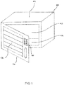
- Figure 1 shows a view of a steam cooker 100 with microwave function with a sealing device according to an embodiment.
- a steam cooker 100 with microwave function comprises a box-shaped device housing 102, a lockable device door 104 with viewing window 106 and various operating and / or control elements 108, a cooking space 110 inside the device housing 102, which is clad with a cooking space jacket 112 and at the bottom of which is a Floor unit 114 is located, in which a floor heating element (not shown) is integrated, which is connected to a floor panel, in particular here a metal plate (not shown).
- the combination device is particularly space-saving as it combines two kitchen devices in one.
- the basic structure of the steam cooker with microwave function is here analogous to the steam cooker with a foil heating element already known by the applicant.
- This steam cooker comprises a foil heating element which is glued to the base plate outside the cooking space.
- the new structure of a steam cooker with microwave function consists of a floor heating element which is connected to a heat conducting plate.
- the heat conducting plate is mounted in the cooking chamber floor by a fastening element, for example a bracket.
- the problem with the construction of the steam cooker with microwave function is that the opening required for installing the floor heating element should be closed again in a steam / water / microwave-tight manner. For this reason, a seal is required to seal the radiator with the floor panel, which is both steam and water-resistant and leak-proof against microwaves.
- the following describes how the steam / water / microwave-tight sealing device can be designed in a particularly favorable manner.
- Figure 2 shows a cross-sectional view of a base unit 114 of the steam cooker with a sealing device according to an embodiment.
- the floor unit 114 of the steam cooker comprises a floor heating element 202, a metal plate 204, the sealing device 206 according to an exemplary embodiment, comprising a sealing element 208 and a microwave protection element 210, a fastening bracket 212, a washer ring 214 with a circumferential upstand 216 and an embossing 218, and a threaded bolt 220 and two nuts 222 and 224 for fixing and securing the sealing device 206.
- the entire base unit 114 is arranged in the cooking space floor 226 of the steamer with microwave function, which in turn is located in the cooking space 110 of the steamer.
- the sealing device 206 is inserted into the embossing 218 of the cooking space 110 and fixed by the metal plate 204 of the floor heating element 202. At the same time, the metal plate 204 positions and centers the sealing device 206 as well.
- the sealing device 206 is fixed by the fastening bracket 212, which is supported on the embossing 218 of the floor unit 114 via the washer ring 214, for example, and clamps the floor heating element 202 via the threaded bolt 220 with the first nut 222. This fixation is finally secured by the second nut 224.
- the first nut 222 is preferably a hexagon nut.
- the position of the sealing device 206 during assembly is secured by the geometry of the embossing 218 in the cooking space jacket 112, which is round, as well as by the washer ring 214 with the circumferential upstand 216 or, alternatively, an upstand directly on the cooking space jacket 112.
- the washer was used here 214 is preferably chosen as an additional component, since the material of the cooking chamber floor is too thin to evenly distribute the force of the locally acting fastening bracket 212 over the entire opening circle.
- the sealing device 206 has the (for example already electrically conductive) sealing element 208 and the microwave protection element 210.
- Sealing device 206 shown is a connection of two elastomer components, comprising a sealing element 208 made of food-safe silicone and a microwave protection element 210, which has a conductive elastomer.
- the sealing element 208 and the microwave protection element 210 are formed as two interlocking polygonal bodies each with an upstand 228, 230, the upstand 228, 230 of both elements engaging in one another.
- the sealing element 208 and the microwave protection element 210 are connected either by gluing the contact points using an adhesive or silicone or by producing the two elements 208, 210 by injection molding or by introducing two different materials into a cavity of an injection molding tool. Linking using an injection mold with an undercut, similar to the shape used for puzzle pieces, would also be conceivable, but it could be problematic due to the fine sealing geometry. Alternatively, the shape of the transition for connecting the two elements 208, 210 can also be designed as a ramp or a staircase.
- Figure 3 shows a cross-sectional view of a base unit 114 of the steam cooker with a sealing device according to an embodiment.
- the floor unit 114 comprises the same parts as that in FIG Figure 2
- the illustrated floor unit 114 of the steam cooker namely the floor heating element 202, the metal plate 204, the sealing device 206 comprising the sealing element 208 and the microwave protection element 210, the mounting bracket 212, the washer 214 with the circumferential upstand 216 and the embossing 218, and the threaded bolt 220 and two Nuts 222, 224.
- the entire base unit 114 is arranged in the cooking chamber floor 226 of the steam cooker 100 with a microwave function, which in turn is located in the cooking chamber 110 of the steam cooker 100.
- the structure of the sealing device 206 differs Figure 3 from the structure of the sealing device 206 Figure 2 .
- the Figure 3 Sealing device 206 presented, the (for example electrically conductive) sealing element 208 and the microwave protection element 210.
- the sealing device 206 shown in it is a combination of two different materials, including, for example, a food-safe one Elastomer sealing element 208 made of silicone and a conductive sealing element or microwave protection element 210 made of a metal knitted fabric.
- FIG. 10 shows an enlarged cross-sectional view of a sealing device 206 according to an embodiment.
- this sealing device 206 has the (for example electrically conductive) sealing element 208 as well as the microwave protection element 210.
- Sealing device 206 shown is a connection of two elastomer components, consisting of a sealing element 208 made of food-safe silicone and a microwave protection element 210 consisting of a conductive elastomer.
- the (electrically conductive) elastomer sealing element from this variant is a silicone which is additionally enriched with electrically conductive substances. This is intended to achieve sufficient electrical conductivity, especially between the cooking space jacket and the floor heating element.
- the sealing element 208 and the microwave protection element 210 are formed as two interlocking polygonal bodies each with a raised edge 228, 230, the raised edges 228, 230 of both elements interlocking.
- the metal plate 204 positions and centers the sealing device 206
- FIG. 10 shows an enlarged cross-sectional view of a sealing device 206 according to an embodiment.
- the sealing device 206 has the (electrically conductive) sealing element 208 and the microwave protection element 210.
- the sealing device 206 shown is a connection of two different elements, consisting of a food-safe elastomer sealing element 208 made of silicone and a conductive sealing element made of a knitted metal fabric 210.
- the metal plate 204 positions and centers the sealing device 206.
- This variant of a sealing device 206 can be used with different geometries of the silicone seal as a sealing element 208, in particular here different sealing lips for contact with the floor heating element or the cooking space jacket.
- the metal knitted fabric as microwave protection element 210 can also be used in various geometries, both round and angular, and in various material thicknesses. In this case, the metal fabric of the metal knitted fabric as the microwave protection element 210 can absorb a slight elastic deformation, but no longer have its original dimensions after a plastic deformation. If it were dismantled, the same component would therefore not be used a second time.
- the metal knitted fabric as the microwave protection element 210 is, for example, as already mentioned, shaped as a hollow body which is around a mandrel has been woven, knitted or wrapped.
- An elastic silicone body can also be provided in the cavity. This could support the metal knitted fabric as a microwave protection element 210 in such a way that it does not get into the plastic area when it is deformed.
- the silicone body can possibly be designed as a monolithic, one-piece and / or foamed core.
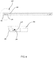
- FIG. 11 shows a schematic illustration of a floor unit 114 with an enlarged sealing element 206.
- the illustrated floor unit 114 comprises, for example, the same structural elements as the floor unit 114 from FIG Figures 2 and 3
- the sealing device 206 shown has, for example, the same components as the sealing device 206 Figure 2 on.
- the bottom unit 114 can be seen in its entirety, while the sealing device 206 can be seen enlarged on the right-hand side of the figure.
- the sealing device 206 is first inserted into the floor unit 114, then the floor heating element 202 is placed, then the floor heating element 202 is pressed into the sealing device 206 by means of an assembly device. Then the cooking space is turned over, then the washer is placed, which centers itself by means of the upstand, and then the fastening bracket is placed and tightened with the first nut. Then the assembly device is loosened and the second nut is put on. Furthermore, it is possible that the upstand is already present before the sealing device 206 is inserted, either by embossing it in the floor material or by an adhesive fastening of the washer before the sealing device 206 is inserted. This can facilitate the positioning of the sealing device 206.
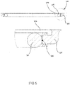
- FIG 7 shows a schematic representation of a base unit 114 with an enlarged sealing element 206 according to an embodiment.
- the illustrated floor unit 114 comprises the same components as the floor unit 114 from FIG Figures 2 , 3 and 6 , the illustrated sealing device 206 has the same components as that Figure 3 on.
- the bottom unit 114 can be seen in its entirety while the sealing device 206 is shown enlarged on the right-hand side of the figure.
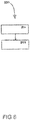
- FIG 8 shows a flowchart of an embodiment of a method 800 for producing the sealing device.
- the method 800 for manufacturing the sealing device includes the following steps.
- a step 801 the sealing element and the microwave protection element are provided.
- step 803 the sealing element and the microwave protection element connected to one another.
- the sealing element and the microwave protection element can be connected to one another by means of gluing with the aid of an adhesive and / or silicone and / or by means of or by being introduced into a cavity of an injection molding tool.
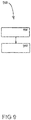
- FIG. 9 shows a flow chart of an exemplary embodiment of a method 900 for the leak-proof sealing of a radiator with a base plate for a combined steam cooker with a microwave function.
- the method 900 for leak-proof sealing of a radiator with a base plate for a combined steam cooker with microwave function has the following steps.
- the sealing device is provided for the leak-proof sealing of the radiator with the floor panel.
- the sealing device is finally installed in the steam cooker for leakproof sealing of the radiator with the floor panel in order to carry out the leakproof sealing of the floor heating element with the floor panel for a combined steam cooker with microwave function.
Landscapes
- Physics & Mathematics (AREA)
- Electromagnetism (AREA)
- Cookers (AREA)
- Electric Ovens (AREA)
Claims (13)
- Cuiseur vapeur (100) à fonction micro-ondes permettant de préparer des plats ou des produits de boulangerie,
le cuiseur vapeur (100) présentant un espace de cuisson (110) comportant un dispositif d'étanchéité (206) comme pare-vapeur vis-à-vis de l'espace de cuisson (110),
le dispositif d'étanchéité (206) présentant un élément d'étanchéité (208) qui présente au moins partiellement un élastomère, en particulier du silicone, et
le dispositif d'étanchéité (206) présentant un élément de protection contre les micro-ondes (210) pour assurer l'étanchéité contre les rayonnements de fuite, lequel présente au moins partiellement un matériau électriquement conducteur,
caractérisé en ce que
l'espace de cuisson (110) présente un corps de chauffage de fond (202) pour l'évaporation de l'eau résiduelle et une enveloppe d'espace de cuisson (112) comportant une plaque de fond (204), le corps de chauffage de fond (202) étant intégré dans la plaque de fond (204), et en ce que le dispositif d'étanchéité (206) est fixé par la plaque de fond (204) du corps de chauffage de fond (202). - Cuiseur vapeur (100) à fonction micro-ondes selon la revendication 1, dans lequel une transition d'étanchéité permettant de relier l'élément d'étanchéité (208) à l'élément de protection contre les micro-ondes (210) est réalisée sous la forme d'une rampe ou d'un escalier.
- Cuiseur vapeur (100) à fonction micro-ondes selon l'une des revendications précédentes, dans lequel l'élément de protection contre les micro-ondes (210) est réalisé sous la forme d'un treillis métallique (210).
- Cuiseur vapeur (100) à fonction micro-ondes selon la revendication 3, dans lequel le treillis métallique (210) est réalisé sous la forme d'un corps creux et/ou est disposé autour d'un mandrin.
- Cuiseur vapeur (100) à fonction micro-ondes selon la revendication 4, dans lequel un corps en silicone est disposé dans un espace creux du treillis métallique (210).
- Procédé (900) permettant l'étanchéité, contre les rayonnements de fuite, d'un corps de chauffage de fond (202) comportant une plaque de fond (204) pour un cuiseur vapeur combiné (100) à fonction micro-ondes, le procédé (900) comprenant l'étape :de mise à disposition (901) du dispositif d'étanchéité (206) pour assurer l'étanchéité, contre les rayonnements de fuite, du corps de chauffage de fond (202) comportant la plaque de fond (204) ;le dispositif d'étanchéité (206) présentant les caractéristiques suivantes :un élément d'étanchéité (208), lequel présente au moins partiellement un élastomère, en particulier du silicone ; etun élément de protection contre les micro-ondes (210), lequel présente au moins partiellement un matériau électriquement conducteur,caractérisé en ce quele procédé (900) comprend l'étape :
de montage (903) du dispositif d'étanchéité (206) dans le cuiseur vapeur (100) pour assurer l'étanchéité, contre les rayonnements de fuite, du corps de chauffage de fond (202) comportant la plaque de fond (204), afin de réaliser l'étanchéité, contre les rayonnements de fuite, du corps de chauffage de fond (202) comportant la plaque de fond (204) pour un cuiseur vapeur combiné (100) à fonction micro-ondes. - Procédé (900) selon la revendication 6, comprenant les étapes :de mise à disposition (801) de l'élément d'étanchéité (208) et de l'élément de protection contre les micro-ondes (210) ; etde liaison (803) de l'élément d'étanchéité (208) à l'élément de protection contre les micro-ondes (210) afin de produire le dispositif d'étanchéité (206).
- Procédé (900) selon la revendication 7, dans lequel, au cours de l'étape de liaison (803), l'élément d'étanchéité (208) est relié à l'élément de protection contre les micro-ondes (210) par collage à l'aide d'un adhésif et/ou de silicone, et/ou ces derniers sont reliés par leur introduction et/ou en les introduisant dans une cavité d'un outil d'injection.
- Procédé (900) selon l'une des revendications 6 à 8 précédentes, dans lequel l'élément d'étanchéité (208) est réalisé de façon à former un pare-vapeur vis-à-vis de l'espace de cuisson (110) du cuiseur vapeur (100).
- Procédé (900) selon l'une des revendications 6 à 9 précédentes, dans lequel l'élément d'étanchéité (208) est relié à l'élément de protection contre les micro-ondes (210) en utilisant un moule d'injection doté d'une contre-dépouille, et/ou une transition d'étanchéité permettant de relier l'élément d'étanchéité (208) à l'élément de protection contre les micro-ondes (210) est réalisée sous la forme d'une rampe ou d'un escalier.
- Procédé (900) selon l'une des revendications 6 à 10 précédentes, dans lequel l'élément de protection contre les micro-ondes (210) est réalisé sous la forme d'un treillis métallique (210).
- Procédé (900) selon la revendication 11, dans lequel le treillis métallique (210) est réalisé sous la forme d'un corps creux et/ou est disposé autour d'un mandrin.
- Procédé (900) selon la revendication 12, dans lequel un corps en silicone est disposé dans un espace creux du treillis métallique (210).
Applications Claiming Priority (1)
| Application Number | Priority Date | Filing Date | Title |
|---|---|---|---|
| DE102017111075.5A DE102017111075B4 (de) | 2017-05-22 | 2017-05-22 | Dichtungsvorrichtung und Verfahren zur leckstrahlsicheren Abdichtung eines Heizkörpers mit einem Bodenblech für einen kombinierten Dampfgarer mit Mikrowellenfunktion, sowie Verfahren zur Herstellung der Dichtungsvorrichtung, Vorrichtung und Computer-Programmprodukt zur Ausführung der Verfahren, sowie Dampfgarer mit Mikrowellenfunktion |
Publications (2)
| Publication Number | Publication Date |
|---|---|
| EP3407679A1 EP3407679A1 (fr) | 2018-11-28 |
| EP3407679B1 true EP3407679B1 (fr) | 2021-01-27 |
Family
ID=62165419
Family Applications (1)
| Application Number | Title | Priority Date | Filing Date |
|---|---|---|---|
| EP18172054.1A Active EP3407679B1 (fr) | 2017-05-22 | 2018-05-14 | Procédé et dispositif d'étanchéité contre les rayonnements de fuite d'un radiateur doté d'une tôle de fond pour un appareil de cuisson à vapeur combiné à fonction d'onde |
Country Status (2)
| Country | Link |
|---|---|
| EP (1) | EP3407679B1 (fr) |
| DE (1) | DE102017111075B4 (fr) |
Families Citing this family (2)
| Publication number | Priority date | Publication date | Assignee | Title |
|---|---|---|---|---|
| JP2020139707A (ja) * | 2019-02-28 | 2020-09-03 | パナソニックIpマネジメント株式会社 | 加熱調理器 |
| BE1031412B1 (de) | 2023-03-08 | 2024-10-08 | Miele & Cie | Gargerät |
Family Cites Families (7)
| Publication number | Priority date | Publication date | Assignee | Title |
|---|---|---|---|---|
| DE2320438A1 (de) * | 1972-06-26 | 1974-01-10 | Litton Industries Inc | Mikrowellenherd |
| DE3137758A1 (de) | 1981-09-23 | 1983-03-31 | Licentia Patent-Verwaltungs-Gmbh, 6000 Frankfurt | Kombinierter herd fuer mikrowellen- und konventionellen widerstandsheizbetrieb |
| FR2604127B1 (fr) | 1986-09-19 | 1990-12-14 | Chausson Usines Sa | Dispositif de climatisation a volet melangeur pour vehicules et applications analogues |
| GB2240884A (en) * | 1990-02-01 | 1991-08-14 | Marling Insulations | Microwave seal |
| US5204503A (en) * | 1991-12-17 | 1993-04-20 | Raytheon Company | Microwave oven having convection and griddle features |
| JP2007115710A (ja) * | 2006-12-22 | 2007-05-10 | Sharp Corp | 加熱調理器 |
| CN201764555U (zh) * | 2010-07-08 | 2011-03-16 | 漳州灿坤实业有限公司 | 一种微波炉炉腔内防漏密封结构 |
-
2017
- 2017-05-22 DE DE102017111075.5A patent/DE102017111075B4/de active Active
-
2018
- 2018-05-14 EP EP18172054.1A patent/EP3407679B1/fr active Active
Non-Patent Citations (1)
| Title |
|---|
| None * |
Also Published As
| Publication number | Publication date |
|---|---|
| DE102017111075B4 (de) | 2018-12-27 |
| EP3407679A1 (fr) | 2018-11-28 |
| DE102017111075A1 (de) | 2018-11-22 |
Similar Documents
| Publication | Publication Date | Title |
|---|---|---|
| DE69822525T2 (de) | Verbesserungen an elektrisch geheizten Kochgefässen | |
| DE4210010A1 (de) | Kochmulde | |
| DE102013216290A1 (de) | Heizeinrichtung und Verfahren zum Betrieb einer Heizeinrichtung | |
| DE4333158A1 (de) | Gerät zum Zubereiten von Speisen | |
| DE102017111075B4 (de) | Dichtungsvorrichtung und Verfahren zur leckstrahlsicheren Abdichtung eines Heizkörpers mit einem Bodenblech für einen kombinierten Dampfgarer mit Mikrowellenfunktion, sowie Verfahren zur Herstellung der Dichtungsvorrichtung, Vorrichtung und Computer-Programmprodukt zur Ausführung der Verfahren, sowie Dampfgarer mit Mikrowellenfunktion | |
| DE202013104227U1 (de) | Elektrischer Samowar | |
| DE19835140A1 (de) | Kochfeld, bestehend aus einer Glaskeramik-Kochfläche | |
| DE102011054687B4 (de) | Gargerät mit Verdampfungseinrichtung und Verfahren zur Herstellung einer Verdampfungseinrichtung | |
| DE102018128475B4 (de) | Gargerät | |
| WO2008138751A1 (fr) | Table de cuisson | |
| EP2594851B1 (fr) | Cuve de plaques de cuisson avec unité de protection | |
| EP2275746B1 (fr) | Four ménager doté d'une isolation thermique | |
| DE102014201426A1 (de) | Gargerät | |
| DE202009013312U1 (de) | Verbindungsvorrichtung | |
| DE69907815T2 (de) | Kochgeschirr mit einem mittels einer Platte und Rillen verstärkten Boden | |
| DE3606117A1 (de) | Kocheinheit mit strahlheizkoerper | |
| DE10202144A1 (de) | Umspritzte Zwischenscheibe mit Dichtprofil | |
| EP3958651A1 (fr) | Dispositif de chauffage électrique | |
| EP1850712B1 (fr) | Bouilloire electrique | |
| EP3543611A1 (fr) | Boîtier électronique pour appareils électroménagers à joint d'étanchéité | |
| DE3126094A1 (de) | Elektrischer ofen mit einer mikrowellen-heizeinrichtung und weiteren elektrischen heizeinrichtungen, darunter eine herausnehmbare grillheizung | |
| EP3323402A1 (fr) | Dispositif de chauffage de surfaces de parois | |
| DE102024120712A1 (de) | Heizvorrichtung für Wasser und wasserführendes Haushaltsgerät mit einer solchen Heizvorrichtung | |
| DE102022004598A1 (de) | Elektrisches Gerät | |
| DE10052565B4 (de) | Vorrichtung zur Beheizung eines Kessels |
Legal Events
| Date | Code | Title | Description |
|---|---|---|---|
| PUAI | Public reference made under article 153(3) epc to a published international application that has entered the european phase |
Free format text: ORIGINAL CODE: 0009012 |
|
| STAA | Information on the status of an ep patent application or granted ep patent |
Free format text: STATUS: THE APPLICATION HAS BEEN PUBLISHED |
|
| AK | Designated contracting states |
Kind code of ref document: A1 Designated state(s): AL AT BE BG CH CY CZ DE DK EE ES FI FR GB GR HR HU IE IS IT LI LT LU LV MC MK MT NL NO PL PT RO RS SE SI SK SM TR |
|
| AX | Request for extension of the european patent |
Extension state: BA ME |
|
| STAA | Information on the status of an ep patent application or granted ep patent |
Free format text: STATUS: REQUEST FOR EXAMINATION WAS MADE |
|
| 17P | Request for examination filed |
Effective date: 20190528 |
|
| RBV | Designated contracting states (corrected) |
Designated state(s): AL AT BE BG CH CY CZ DE DK EE ES FI FR GB GR HR HU IE IS IT LI LT LU LV MC MK MT NL NO PL PT RO RS SE SI SK SM TR |
|
| GRAP | Despatch of communication of intention to grant a patent |
Free format text: ORIGINAL CODE: EPIDOSNIGR1 |
|
| STAA | Information on the status of an ep patent application or granted ep patent |
Free format text: STATUS: GRANT OF PATENT IS INTENDED |
|
| INTG | Intention to grant announced |
Effective date: 20201009 |
|
| GRAS | Grant fee paid |
Free format text: ORIGINAL CODE: EPIDOSNIGR3 |
|
| GRAA | (expected) grant |
Free format text: ORIGINAL CODE: 0009210 |
|
| STAA | Information on the status of an ep patent application or granted ep patent |
Free format text: STATUS: THE PATENT HAS BEEN GRANTED |
|
| AK | Designated contracting states |
Kind code of ref document: B1 Designated state(s): AL AT BE BG CH CY CZ DE DK EE ES FI FR GB GR HR HU IE IS IT LI LT LU LV MC MK MT NL NO PL PT RO RS SE SI SK SM TR |
|
| REG | Reference to a national code |
Ref country code: GB Ref legal event code: FG4D Free format text: NOT ENGLISH |
|
| REG | Reference to a national code |
Ref country code: CH Ref legal event code: NV Representative=s name: COSMOVICI INTELLECTUAL PROPERTY SARL, CH Ref country code: CH Ref legal event code: EP |
|
| REG | Reference to a national code |
Ref country code: AT Ref legal event code: REF Ref document number: 1359484 Country of ref document: AT Kind code of ref document: T Effective date: 20210215 |
|
| REG | Reference to a national code |
Ref country code: IE Ref legal event code: FG4D Free format text: LANGUAGE OF EP DOCUMENT: GERMAN |
|
| REG | Reference to a national code |
Ref country code: DE Ref legal event code: R096 Ref document number: 502018003771 Country of ref document: DE |
|
| REG | Reference to a national code |
Ref country code: NL Ref legal event code: FP |
|
| REG | Reference to a national code |
Ref country code: LT Ref legal event code: MG9D |
|
| PG25 | Lapsed in a contracting state [announced via postgrant information from national office to epo] |
Ref country code: NO Free format text: LAPSE BECAUSE OF FAILURE TO SUBMIT A TRANSLATION OF THE DESCRIPTION OR TO PAY THE FEE WITHIN THE PRESCRIBED TIME-LIMIT Effective date: 20210427 Ref country code: PT Free format text: LAPSE BECAUSE OF FAILURE TO SUBMIT A TRANSLATION OF THE DESCRIPTION OR TO PAY THE FEE WITHIN THE PRESCRIBED TIME-LIMIT Effective date: 20210527 Ref country code: LT Free format text: LAPSE BECAUSE OF FAILURE TO SUBMIT A TRANSLATION OF THE DESCRIPTION OR TO PAY THE FEE WITHIN THE PRESCRIBED TIME-LIMIT Effective date: 20210127 Ref country code: BG Free format text: LAPSE BECAUSE OF FAILURE TO SUBMIT A TRANSLATION OF THE DESCRIPTION OR TO PAY THE FEE WITHIN THE PRESCRIBED TIME-LIMIT Effective date: 20210427 Ref country code: FI Free format text: LAPSE BECAUSE OF FAILURE TO SUBMIT A TRANSLATION OF THE DESCRIPTION OR TO PAY THE FEE WITHIN THE PRESCRIBED TIME-LIMIT Effective date: 20210127 Ref country code: GR Free format text: LAPSE BECAUSE OF FAILURE TO SUBMIT A TRANSLATION OF THE DESCRIPTION OR TO PAY THE FEE WITHIN THE PRESCRIBED TIME-LIMIT Effective date: 20210428 Ref country code: HR Free format text: LAPSE BECAUSE OF FAILURE TO SUBMIT A TRANSLATION OF THE DESCRIPTION OR TO PAY THE FEE WITHIN THE PRESCRIBED TIME-LIMIT Effective date: 20210127 |
|
| PG25 | Lapsed in a contracting state [announced via postgrant information from national office to epo] |
Ref country code: LV Free format text: LAPSE BECAUSE OF FAILURE TO SUBMIT A TRANSLATION OF THE DESCRIPTION OR TO PAY THE FEE WITHIN THE PRESCRIBED TIME-LIMIT Effective date: 20210127 Ref country code: RS Free format text: LAPSE BECAUSE OF FAILURE TO SUBMIT A TRANSLATION OF THE DESCRIPTION OR TO PAY THE FEE WITHIN THE PRESCRIBED TIME-LIMIT Effective date: 20210127 Ref country code: PL Free format text: LAPSE BECAUSE OF FAILURE TO SUBMIT A TRANSLATION OF THE DESCRIPTION OR TO PAY THE FEE WITHIN THE PRESCRIBED TIME-LIMIT Effective date: 20210127 Ref country code: SE Free format text: LAPSE BECAUSE OF FAILURE TO SUBMIT A TRANSLATION OF THE DESCRIPTION OR TO PAY THE FEE WITHIN THE PRESCRIBED TIME-LIMIT Effective date: 20210127 |
|
| PG25 | Lapsed in a contracting state [announced via postgrant information from national office to epo] |
Ref country code: IS Free format text: LAPSE BECAUSE OF FAILURE TO SUBMIT A TRANSLATION OF THE DESCRIPTION OR TO PAY THE FEE WITHIN THE PRESCRIBED TIME-LIMIT Effective date: 20210527 |
|
| REG | Reference to a national code |
Ref country code: DE Ref legal event code: R097 Ref document number: 502018003771 Country of ref document: DE |
|
| PG25 | Lapsed in a contracting state [announced via postgrant information from national office to epo] |
Ref country code: CZ Free format text: LAPSE BECAUSE OF FAILURE TO SUBMIT A TRANSLATION OF THE DESCRIPTION OR TO PAY THE FEE WITHIN THE PRESCRIBED TIME-LIMIT Effective date: 20210127 Ref country code: EE Free format text: LAPSE BECAUSE OF FAILURE TO SUBMIT A TRANSLATION OF THE DESCRIPTION OR TO PAY THE FEE WITHIN THE PRESCRIBED TIME-LIMIT Effective date: 20210127 Ref country code: SM Free format text: LAPSE BECAUSE OF FAILURE TO SUBMIT A TRANSLATION OF THE DESCRIPTION OR TO PAY THE FEE WITHIN THE PRESCRIBED TIME-LIMIT Effective date: 20210127 |
|
| PG25 | Lapsed in a contracting state [announced via postgrant information from national office to epo] |
Ref country code: SK Free format text: LAPSE BECAUSE OF FAILURE TO SUBMIT A TRANSLATION OF THE DESCRIPTION OR TO PAY THE FEE WITHIN THE PRESCRIBED TIME-LIMIT Effective date: 20210127 Ref country code: DK Free format text: LAPSE BECAUSE OF FAILURE TO SUBMIT A TRANSLATION OF THE DESCRIPTION OR TO PAY THE FEE WITHIN THE PRESCRIBED TIME-LIMIT Effective date: 20210127 Ref country code: RO Free format text: LAPSE BECAUSE OF FAILURE TO SUBMIT A TRANSLATION OF THE DESCRIPTION OR TO PAY THE FEE WITHIN THE PRESCRIBED TIME-LIMIT Effective date: 20210127 |
|
| PLBE | No opposition filed within time limit |
Free format text: ORIGINAL CODE: 0009261 |
|
| STAA | Information on the status of an ep patent application or granted ep patent |
Free format text: STATUS: NO OPPOSITION FILED WITHIN TIME LIMIT |
|
| 26N | No opposition filed |
Effective date: 20211028 |
|
| PG25 | Lapsed in a contracting state [announced via postgrant information from national office to epo] |
Ref country code: ES Free format text: LAPSE BECAUSE OF FAILURE TO SUBMIT A TRANSLATION OF THE DESCRIPTION OR TO PAY THE FEE WITHIN THE PRESCRIBED TIME-LIMIT Effective date: 20210127 Ref country code: AL Free format text: LAPSE BECAUSE OF FAILURE TO SUBMIT A TRANSLATION OF THE DESCRIPTION OR TO PAY THE FEE WITHIN THE PRESCRIBED TIME-LIMIT Effective date: 20210127 Ref country code: LU Free format text: LAPSE BECAUSE OF NON-PAYMENT OF DUE FEES Effective date: 20210514 Ref country code: MC Free format text: LAPSE BECAUSE OF FAILURE TO SUBMIT A TRANSLATION OF THE DESCRIPTION OR TO PAY THE FEE WITHIN THE PRESCRIBED TIME-LIMIT Effective date: 20210127 |
|
| PG25 | Lapsed in a contracting state [announced via postgrant information from national office to epo] |
Ref country code: SI Free format text: LAPSE BECAUSE OF FAILURE TO SUBMIT A TRANSLATION OF THE DESCRIPTION OR TO PAY THE FEE WITHIN THE PRESCRIBED TIME-LIMIT Effective date: 20210127 |
|
| PG25 | Lapsed in a contracting state [announced via postgrant information from national office to epo] |
Ref country code: IT Free format text: LAPSE BECAUSE OF FAILURE TO SUBMIT A TRANSLATION OF THE DESCRIPTION OR TO PAY THE FEE WITHIN THE PRESCRIBED TIME-LIMIT Effective date: 20210127 Ref country code: IE Free format text: LAPSE BECAUSE OF NON-PAYMENT OF DUE FEES Effective date: 20210514 |
|
| PG25 | Lapsed in a contracting state [announced via postgrant information from national office to epo] |
Ref country code: IS Free format text: LAPSE BECAUSE OF FAILURE TO SUBMIT A TRANSLATION OF THE DESCRIPTION OR TO PAY THE FEE WITHIN THE PRESCRIBED TIME-LIMIT Effective date: 20210527 Ref country code: FR Free format text: LAPSE BECAUSE OF NON-PAYMENT OF DUE FEES Effective date: 20210531 |
|
| GBPC | Gb: european patent ceased through non-payment of renewal fee |
Effective date: 20220514 |
|
| REG | Reference to a national code |
Ref country code: DE Ref legal event code: R084 Ref document number: 502018003771 Country of ref document: DE |
|
| PG25 | Lapsed in a contracting state [announced via postgrant information from national office to epo] |
Ref country code: GB Free format text: LAPSE BECAUSE OF NON-PAYMENT OF DUE FEES Effective date: 20220514 |
|
| PG25 | Lapsed in a contracting state [announced via postgrant information from national office to epo] |
Ref country code: CY Free format text: LAPSE BECAUSE OF FAILURE TO SUBMIT A TRANSLATION OF THE DESCRIPTION OR TO PAY THE FEE WITHIN THE PRESCRIBED TIME-LIMIT Effective date: 20210127 |
|
| P01 | Opt-out of the competence of the unified patent court (upc) registered |
Effective date: 20230528 |
|
| PG25 | Lapsed in a contracting state [announced via postgrant information from national office to epo] |
Ref country code: HU Free format text: LAPSE BECAUSE OF FAILURE TO SUBMIT A TRANSLATION OF THE DESCRIPTION OR TO PAY THE FEE WITHIN THE PRESCRIBED TIME-LIMIT; INVALID AB INITIO Effective date: 20180514 |
|
| PG25 | Lapsed in a contracting state [announced via postgrant information from national office to epo] |
Ref country code: MK Free format text: LAPSE BECAUSE OF FAILURE TO SUBMIT A TRANSLATION OF THE DESCRIPTION OR TO PAY THE FEE WITHIN THE PRESCRIBED TIME-LIMIT Effective date: 20210127 |
|
| PG25 | Lapsed in a contracting state [announced via postgrant information from national office to epo] |
Ref country code: MT Free format text: LAPSE BECAUSE OF FAILURE TO SUBMIT A TRANSLATION OF THE DESCRIPTION OR TO PAY THE FEE WITHIN THE PRESCRIBED TIME-LIMIT Effective date: 20210127 |
|
| PGFP | Annual fee paid to national office [announced via postgrant information from national office to epo] |
Ref country code: NL Payment date: 20250526 Year of fee payment: 8 |
|
| PGFP | Annual fee paid to national office [announced via postgrant information from national office to epo] |
Ref country code: DE Payment date: 20250531 Year of fee payment: 8 |
|
| PGFP | Annual fee paid to national office [announced via postgrant information from national office to epo] |
Ref country code: BE Payment date: 20250526 Year of fee payment: 8 |
|
| PGFP | Annual fee paid to national office [announced via postgrant information from national office to epo] |
Ref country code: CH Payment date: 20250601 Year of fee payment: 8 |
|
| PGFP | Annual fee paid to national office [announced via postgrant information from national office to epo] |
Ref country code: AT Payment date: 20250520 Year of fee payment: 8 |
|
| PG25 | Lapsed in a contracting state [announced via postgrant information from national office to epo] |
Ref country code: TR Free format text: LAPSE BECAUSE OF FAILURE TO SUBMIT A TRANSLATION OF THE DESCRIPTION OR TO PAY THE FEE WITHIN THE PRESCRIBED TIME-LIMIT Effective date: 20210127 |