EP3407590A1 - Dispositif de prise en charge d'imagerie et procédé de prise en charge d'imagerie - Google Patents
Dispositif de prise en charge d'imagerie et procédé de prise en charge d'imagerie Download PDFInfo
- Publication number
- EP3407590A1 EP3407590A1 EP17741248.3A EP17741248A EP3407590A1 EP 3407590 A1 EP3407590 A1 EP 3407590A1 EP 17741248 A EP17741248 A EP 17741248A EP 3407590 A1 EP3407590 A1 EP 3407590A1
- Authority
- EP
- European Patent Office
- Prior art keywords
- imaging
- information
- pixel density
- imaged
- unit
- Prior art date
- Legal status (The legal status is an assumption and is not a legal conclusion. Google has not performed a legal analysis and makes no representation as to the accuracy of the status listed.)
- Granted
Links
- 238000003384 imaging method Methods 0.000 title claims abstract description 526
- 238000000034 method Methods 0.000 title claims abstract description 14
- 239000004567 concrete Substances 0.000 claims description 10
- 229910000831 Steel Inorganic materials 0.000 claims description 5
- 239000010959 steel Substances 0.000 claims description 5
- 238000004891 communication Methods 0.000 description 21
- 238000012545 processing Methods 0.000 description 17
- 238000010586 diagram Methods 0.000 description 15
- 238000007689 inspection Methods 0.000 description 9
- 238000005516 engineering process Methods 0.000 description 8
- 238000003908 quality control method Methods 0.000 description 6
- 238000011960 computer-aided design Methods 0.000 description 5
- 230000003287 optical effect Effects 0.000 description 5
- 230000006870 function Effects 0.000 description 4
- 238000009434 installation Methods 0.000 description 4
- 239000000463 material Substances 0.000 description 3
- 239000011513 prestressed concrete Substances 0.000 description 3
- 238000005259 measurement Methods 0.000 description 2
- 238000012986 modification Methods 0.000 description 2
- 230000004048 modification Effects 0.000 description 2
- 239000011150 reinforced concrete Substances 0.000 description 2
- 238000001514 detection method Methods 0.000 description 1
- 239000004973 liquid crystal related substance Substances 0.000 description 1
- 238000003466 welding Methods 0.000 description 1
Images


Classifications
-
- G—PHYSICS
- G03—PHOTOGRAPHY; CINEMATOGRAPHY; ANALOGOUS TECHNIQUES USING WAVES OTHER THAN OPTICAL WAVES; ELECTROGRAPHY; HOLOGRAPHY
- G03B—APPARATUS OR ARRANGEMENTS FOR TAKING PHOTOGRAPHS OR FOR PROJECTING OR VIEWING THEM; APPARATUS OR ARRANGEMENTS EMPLOYING ANALOGOUS TECHNIQUES USING WAVES OTHER THAN OPTICAL WAVES; ACCESSORIES THEREFOR
- G03B15/00—Special procedures for taking photographs; Apparatus therefor
-
- G—PHYSICS
- G01—MEASURING; TESTING
- G01M—TESTING STATIC OR DYNAMIC BALANCE OF MACHINES OR STRUCTURES; TESTING OF STRUCTURES OR APPARATUS, NOT OTHERWISE PROVIDED FOR
- G01M5/00—Investigating the elasticity of structures, e.g. deflection of bridges or air-craft wings
- G01M5/0033—Investigating the elasticity of structures, e.g. deflection of bridges or air-craft wings by determining damage, crack or wear
-
- G—PHYSICS
- G01—MEASURING; TESTING
- G01M—TESTING STATIC OR DYNAMIC BALANCE OF MACHINES OR STRUCTURES; TESTING OF STRUCTURES OR APPARATUS, NOT OTHERWISE PROVIDED FOR
- G01M5/00—Investigating the elasticity of structures, e.g. deflection of bridges or air-craft wings
- G01M5/0091—Investigating the elasticity of structures, e.g. deflection of bridges or air-craft wings by using electromagnetic excitation or detection
-
- G—PHYSICS
- G01—MEASURING; TESTING
- G01N—INVESTIGATING OR ANALYSING MATERIALS BY DETERMINING THEIR CHEMICAL OR PHYSICAL PROPERTIES
- G01N21/00—Investigating or analysing materials by the use of optical means, i.e. using sub-millimetre waves, infrared, visible or ultraviolet light
- G01N21/84—Systems specially adapted for particular applications
- G01N21/88—Investigating the presence of flaws or contamination
- G01N21/8806—Specially adapted optical and illumination features
-
- G—PHYSICS
- G01—MEASURING; TESTING
- G01N—INVESTIGATING OR ANALYSING MATERIALS BY DETERMINING THEIR CHEMICAL OR PHYSICAL PROPERTIES
- G01N21/00—Investigating or analysing materials by the use of optical means, i.e. using sub-millimetre waves, infrared, visible or ultraviolet light
- G01N21/84—Systems specially adapted for particular applications
- G01N21/88—Investigating the presence of flaws or contamination
- G01N21/8851—Scan or image signal processing specially adapted therefor, e.g. for scan signal adjustment, for detecting different kinds of defects, for compensating for structures, markings, edges
-
- G—PHYSICS
- G01—MEASURING; TESTING
- G01N—INVESTIGATING OR ANALYSING MATERIALS BY DETERMINING THEIR CHEMICAL OR PHYSICAL PROPERTIES
- G01N21/00—Investigating or analysing materials by the use of optical means, i.e. using sub-millimetre waves, infrared, visible or ultraviolet light
- G01N21/84—Systems specially adapted for particular applications
- G01N21/88—Investigating the presence of flaws or contamination
- G01N21/95—Investigating the presence of flaws or contamination characterised by the material or shape of the object to be examined
- G01N21/9515—Objects of complex shape, e.g. examined with use of a surface follower device
-
- G—PHYSICS
- G03—PHOTOGRAPHY; CINEMATOGRAPHY; ANALOGOUS TECHNIQUES USING WAVES OTHER THAN OPTICAL WAVES; ELECTROGRAPHY; HOLOGRAPHY
- G03B—APPARATUS OR ARRANGEMENTS FOR TAKING PHOTOGRAPHS OR FOR PROJECTING OR VIEWING THEM; APPARATUS OR ARRANGEMENTS EMPLOYING ANALOGOUS TECHNIQUES USING WAVES OTHER THAN OPTICAL WAVES; ACCESSORIES THEREFOR
- G03B17/00—Details of cameras or camera bodies; Accessories therefor
- G03B17/56—Accessories
- G03B17/561—Support related camera accessories
-
- G—PHYSICS
- G06—COMPUTING; CALCULATING OR COUNTING
- G06T—IMAGE DATA PROCESSING OR GENERATION, IN GENERAL
- G06T7/00—Image analysis
- G06T7/0002—Inspection of images, e.g. flaw detection
-
- G—PHYSICS
- G06—COMPUTING; CALCULATING OR COUNTING
- G06T—IMAGE DATA PROCESSING OR GENERATION, IN GENERAL
- G06T7/00—Image analysis
- G06T7/50—Depth or shape recovery
-
- G—PHYSICS
- G06—COMPUTING; CALCULATING OR COUNTING
- G06T—IMAGE DATA PROCESSING OR GENERATION, IN GENERAL
- G06T7/00—Image analysis
- G06T7/70—Determining position or orientation of objects or cameras
-
- G—PHYSICS
- G06—COMPUTING; CALCULATING OR COUNTING
- G06T—IMAGE DATA PROCESSING OR GENERATION, IN GENERAL
- G06T7/00—Image analysis
- G06T7/80—Analysis of captured images to determine intrinsic or extrinsic camera parameters, i.e. camera calibration
-
- H—ELECTRICITY
- H04—ELECTRIC COMMUNICATION TECHNIQUE
- H04N—PICTORIAL COMMUNICATION, e.g. TELEVISION
- H04N23/00—Cameras or camera modules comprising electronic image sensors; Control thereof
- H04N23/60—Control of cameras or camera modules
- H04N23/64—Computer-aided capture of images, e.g. transfer from script file into camera, check of taken image quality, advice or proposal for image composition or decision on when to take image
-
- H—ELECTRICITY
- H04—ELECTRIC COMMUNICATION TECHNIQUE
- H04N—PICTORIAL COMMUNICATION, e.g. TELEVISION
- H04N23/00—Cameras or camera modules comprising electronic image sensors; Control thereof
- H04N23/60—Control of cameras or camera modules
- H04N23/69—Control of means for changing angle of the field of view, e.g. optical zoom objectives or electronic zooming
-
- H—ELECTRICITY
- H04—ELECTRIC COMMUNICATION TECHNIQUE
- H04N—PICTORIAL COMMUNICATION, e.g. TELEVISION
- H04N23/00—Cameras or camera modules comprising electronic image sensors; Control thereof
- H04N23/60—Control of cameras or camera modules
- H04N23/695—Control of camera direction for changing a field of view, e.g. pan, tilt or based on tracking of objects
-
- H—ELECTRICITY
- H04—ELECTRIC COMMUNICATION TECHNIQUE
- H04N—PICTORIAL COMMUNICATION, e.g. TELEVISION
- H04N7/00—Television systems
- H04N7/18—Closed-circuit television [CCTV] systems, i.e. systems in which the video signal is not broadcast
-
- G—PHYSICS
- G01—MEASURING; TESTING
- G01C—MEASURING DISTANCES, LEVELS OR BEARINGS; SURVEYING; NAVIGATION; GYROSCOPIC INSTRUMENTS; PHOTOGRAMMETRY OR VIDEOGRAMMETRY
- G01C9/00—Measuring inclination, e.g. by clinometers, by levels
-
- G—PHYSICS
- G06—COMPUTING; CALCULATING OR COUNTING
- G06T—IMAGE DATA PROCESSING OR GENERATION, IN GENERAL
- G06T2207/00—Indexing scheme for image analysis or image enhancement
- G06T2207/30—Subject of image; Context of image processing
- G06T2207/30168—Image quality inspection
-
- G—PHYSICS
- G06—COMPUTING; CALCULATING OR COUNTING
- G06T—IMAGE DATA PROCESSING OR GENERATION, IN GENERAL
- G06T2207/00—Indexing scheme for image analysis or image enhancement
- G06T2207/30—Subject of image; Context of image processing
- G06T2207/30181—Earth observation
- G06T2207/30184—Infrastructure
Definitions
- the present invention relates to an imaging support device and an imaging support method that support the imaging of a structure performed using an imaging device.
- JP2007-280282A discloses a technology that receives global positioning system (GPS) radio waves by a portable terminal to calculate the position information of the portable terminal and determines whether or not the position information of the portable terminal is present in a predetermined range to check whether or not structures positioned near the portable terminal are structures to be inspected.
- GPS global positioning system
- JP2009-85785A discloses a technology that calculates the inclination angle of a wall surface with respect to the optical axis of an imaging device on the basis of a distance to the wall surface, which is detected by a pair of left and right distance sensors, and the pan angle and the tilt angle of the imaging device (camera), and makes the inclination angle be in an allowable range in the measurement of the width of a crack of the wall surface.
- JP2006-309742A discloses a technology that determines whether or not a resolution is a resolution required to specify a vehicle number or a driver on the basis of the number of imaging pixels, the angle of view of an optical system, and a distance to a subject.
- an imaging plan for imaging the surface to be imaged of a structure in a state in which an imaging device faces the surface to be imaged in a direction perpendicular to the surface to be imaged and acquiring an image satisfying required image quality is made.
- a crack having a narrow width (for example, 0.1 mm) needs to be capable of being recognized in the inspection of a crack of a concrete member, the crack needs to be imaged with high image quality so as to be sufficiently recognized. Even in the inspection of a crevice of a steel member, the crevice needs to be imaged with high image quality so as to be sufficiently recognized. In a case where it is found that an image is taken with low image quality not allowing damage, such as a crack and a crevice, to be sufficiently recognized, an image needs to be taken again. Further, in a case where it is ignored that an image has been taken with low image quality not allowing damage to be sufficiently recognized, there is a possibility that inappropriate inspection results may be reported. For example, there are a possibility that a crack, which is narrow but critical, may be ignored and a possibility that a large crack may be evaluated as a narrow crack.
- JP2007-280282A discloses a technology that checks whether or not structures positioned near the portable terminal are structures to be inspected on the basis of the position information of the portable terminal obtained using GPS, but does not disclose a technology that determines whether or not an image satisfies required image quality to reliably acquire an image satisfying the required image quality.
- JP2009-85785A merely discloses a technology that makes the inclination angle of a wall surface with respect to the optical axis of the imaging device be in an allowable range, that is, a technology that images a wall surface as the surface to be imaged of the structure in a state in which the imaging device faces the wall surface in a direction perpendicular to the wall surface so that a wall surface satisfying required image quality can be taken.
- a technology that images a wall surface as the surface to be imaged of the structure in a state in which the imaging device faces the wall surface in a direction perpendicular to the wall surface so that a wall surface satisfying required image quality can be taken In a case in which an image cannot be taken in a state in which the imaging device faces the surface to be imaged of the structure in a direction perpendicular to the surface to be imaged, the image quality (detection accuracy) of a crack deteriorates.
- an imaging device is disposed so as to face a license plate or a driver's face in a direction perpendicular to the license plate or the driver's face in JP2006-309742A , there is a possibility that a vehicle number or a driver cannot be specified in a case in which the imaging device takes an image in a state in which the imaging device does not face the license plate or the driver's face in a direction perpendicular to the license plate or the driver's face.
- the invention has been made in consideration of the above-mentioned circumstances, and an object of the invention is to provide an imaging support device and an imaging support method that allow an image, which satisfies required image quality, to be reliably acquired by reliably recognizing whether or not an image satisfies required image quality even in a case in which an image cannot be taken in a state in which an imaging device faces the surface to be imaged of a structure in a direction perpendicular to the surface to be imaged.
- an imaging support device supports imaging of a structure performed using an imaging device and comprises: a required pixel density information-acquisition unit that acquires required pixel density information of a surface to be imaged of the structure required for recognition of a damage state of the structure; an imaging performance information-acquisition unit that acquires imaging performance information of the imaging device including information on the number of pixels of an imaging element of the imaging device, size information of the imaging element of the imaging device, and information on a focal length of an imaging lens of the imaging device; a distance information-acquisition unit that acquires distance information on a distance between the imaging device and the surface to be imaged of the structure; an inclination angle information-acquisition unit that acquires inclination angle information on an inclination angle of the surface to be imaged of the structure with respect to a direction orthogonal to an imaging direction of the imaging device; an actual pixel density-calculation unit that calculates actual pixel density of the surface to be imaged of the structure on the basis of the acquired
- the actual pixel density of the surface to be imaged of the structure is calculated on the basis of the imaging performance information of the imaging device, the distance information on a distance between the imaging device and the surface to be imaged of the structure, and the inclination angle information on an inclination angle of the surface to be imaged of the structure; and it is determined whether or not the actual pixel density matches the required pixel density information. Accordingly, it is possible to reliably recognize whether or not an image satisfies required image quality even in a case in which an image cannot be taken in a state in which the imaging device faces the surface to be imaged of the structure in a direction perpendicular to the surface to be imaged. Accordingly, it is possible to reliably acquire an image satisfying the required image quality.
- the actual pixel density-calculation unit calculates the actual pixel density, which is to be obtained in a case in which the inclination angle information is an angle ⁇ larger than 0°, by multiplying the actual pixel density, which is to be obtained in a case in which the inclination angle information is 0°, and cos ⁇ together.
- An imaging support device further comprises a requirement matching range-determination unit that determines a requirement matching range, in which the actual pixel density matches the required pixel density information, in an imageable range of the surface to be imaged of the structure corresponding to an angle of view of the imaging device.
- a requirement matching range-determination unit that determines a requirement matching range, in which the actual pixel density matches the required pixel density information, in an imageable range of the surface to be imaged of the structure corresponding to an angle of view of the imaging device.
- the required pixel density information-acquisition unit acquires the required pixel density information on the basis of at least one of the type of a member of the structure or the type of damage to the structure.
- An imaging support device further comprises an output unit that outputs results of the determination.
- the output unit outputs information prompting the imaging device to move in a case where it is determined that the actual pixel density does not match the required pixel density information.
- An imaging support device further comprises: an imaging control computing unit that computes an imaging position and an imaging direction of the imaging device, which allow the actual pixel density to match the required pixel density information, on the basis of a current imaging position and a current imaging direction of the imaging device in a case where it is determined that the actual pixel density does not match the required pixel density information; and an imaging control unit that controls the imaging position and the imaging direction of the imaging device on the basis of computation results of the imaging control computing unit.
- the pixel density-determination unit determines whether or not the actual pixel density satisfies the required pixel density information over the plurality of times of imaging while using pixel density, which is obtained from the surface to be imaged of the structure at each imaging of the structure, as the actual pixel density.
- the pixel density-determination unit switches the required pixel density information, which is to be compared with the actual pixel density, according to the type of the imaging device or the type of an apparatus on which the imaging device is mounted.
- An imaging support device further comprises: a drawing information-acquisition unit that acquires drawing information of the structure; an imaging point specification unit that specifies an imaging point of the structure on the basis of the acquired drawing information; and an imaging planning unit that determines an imaging position and an imaging direction of each imaging of the structure on the basis of the specified imaging point of the structure, and generates imaging plan information representing the imaging position and the imaging direction of each imaging of the structure.
- the structure includes at least one of a concrete member or a steel member as a member to be inspected.
- the structure includes a member in which at least one of a crack or a crevice is generated as damage to be recognized.
- An imaging support method of the invention supports imaging of a structure performed using an imaging device and comprises: a step of acquiring required pixel density information of a surface to be imaged of the structure required for recognition of a damage state of the structure; a step of acquiring imaging performance information of the imaging device including information on the number of pixels of an imaging element of the imaging device, size information of the imaging element of the imaging device, and information on a focal length of an imaging lens of the imaging device; a step of acquiring distance information on a distance between the imaging device and the surface to be imaged of the structure; a step of acquiring inclination angle information on an inclination angle of the surface to be imaged of the structure with respect to a direction orthogonal to an imaging direction of the imaging device; a step of calculating actual pixel density of the surface to be imaged of the structure on the basis of the acquired imaging performance information, the acquired distance information, and the acquired inclination angle information; and a step of determining whether or not the calculated actual pixel density matches the required pixel density information.
- the imaging device since it is possible to reliably recognize whether or not an image satisfies required image quality even in a case in which an image cannot be taken in a state in which the imaging device faces the surface to be imaged of the structure in a direction perpendicular to the surface to be imaged, it is possible to reliably acquire an image satisfying the required image quality.
- Fig. 1 is a block diagram showing an example of the configuration of an imaging support device according to a first embodiment.
- the imaging support device 10 includes: a radio communication unit 12 that communicates with an imaging device 200 by radio; a storage unit 14 that stores the required pixel density information of the surface to be imaged of a structure, which is required for the recognition of the damage state of the structure, and the imaging performance information of the imaging device 200; a required pixel density information-acquisition unit 16 that acquires the required pixel density information from the storage unit 14; an imaging performance information-acquisition unit 18 that acquires the imaging performance information of the imaging device 200, which is used to image the structure, from the storage unit 14; a distance information-acquisition unit 20 that acquires distance information, which represents a distance between the imaging device 200 and the surface to be imaged of the structure (hereinafter, referred to as an imaging distance); an inclination angle information-acquisition unit 22 that acquires inclination angle information on the inclination angle of the surface to be imaged of the structure with respect to a direction orthogonal to an imaging direction of the imaging device 200; an actual pixel density-calculation unit 24 that calculates the actual pixel density of
- the radio communication unit 12 is formed of a radio communication device that communicates with the imaging device 200 by radio.
- the storage unit 14 is a storage device that is provided in the imaging support device 10, and includes a read only memory (ROM), a random access memory (RAM), and an electrically erasable programmable read only memory (EEPROM). Other storage devices may be used.
- ROM read only memory
- RAM random access memory
- EEPROM electrically erasable programmable read only memory
- the required pixel density information and the imaging performance information are stored in the storage unit 14 of the imaging support device 10 in this embodiment, but the required pixel density information and the imaging performance information are stored in a storage device provided outside the imaging support device 10 and the required pixel density information and the imaging performance information may be acquired from the storage device provided outside the imaging support device 10.
- the required pixel density information is information that represents pixel density required for the surface to be imaged of the structure in a taken image (hereinafter, referred to as "required pixel density").
- the "required pixel density” of this embodiment is the number of pixels per unit length of the surface to be imaged in a taken image.
- the "required pixel density” of this example may be expressed by the number of pixels per unit area.
- the required pixel density information may be expressed by an inverse number of the required pixel density (required resolution). Even in the case of a concrete member, the required pixel density information varies depending on the type of the concrete member.
- the required pixel density information of a reinforced concrete (RC) material is 1.0 [mm/pixel] and the required pixel density information of a pre-stressed concrete (PC) material is 0.5 [mm/pixel].
- a PC material is used and a crack having a width of 0.1 mm needs to be checked. For this reason, a resolution of 0.5 [mm/pixel] or less corresponding to five times the width of a crack is required.
- the required pixel density information also varies depending on the type of damage.
- the required pixel density information-acquisition unit 16 acquires the required pixel density information on the basis of at least one of the type of a member of the structure or the type of damage to the structure.
- the imaging performance information which is acquired by the imaging performance information-acquisition unit 18, includes information on the number of pixels of the imaging element of the imaging device 200, size information of the imaging element of the imaging device 200, and information on the focal length of the imaging lens of the imaging device 200.
- the information on the number of pixels is information corresponding to the number of pixels of the imaging element of the imaging device 200 (hereinafter, referred to as "the number of pixels of the imaging element”), and is not limited to information that is expressed by the number of pixels itself.
- the size information is information corresponding to the size of the imaging element of the imaging device 200 (hereinafter, referred to as "the size of the imaging element”), and is not limited to information that is expressed by the physical quantity of a size.
- the information on the focal length is information corresponding to the focal length of the imaging lens of the imaging device 200, and is not limited to information that is expressed by a focal length itself.
- the size information may be identification information, such as "full size”.
- the imaging performance information is expressed by the angle of view and the number of pixels of the imaging element, which are determined depending on a focal length and the size of the imaging element, is also included in the invention.
- the distance information-acquisition unit 20 can acquire distance information by various methods. First, there is an aspect where the imaging device 200 includes two lenses and distance information is acquired through stereo measurement. Second, there is an aspect where the imaging device 200 is further provided with a range finder. The distance information may be acquired by a time of flight (TOF) method. The distance information may be acquired by other methods.
- TOF time of flight
- An aspect where inclination angle information is acquired by the inclination angle information-acquisition unit 22 may be any one of an aspect where the inclination angle information is directly acquired and an aspect where the inclination angle information is calculated.
- the inclination angle information-acquisition unit 22 of this embodiment calculates the inclination angle information from the imaging distances of two or more points on the surface to be imaged.
- the inclination angle information may be acquired by other methods.
- the inclination angle information is information that represents the inclination of the surface to be imaged with respect to a direction orthogonal to the imaging direction (hereinafter, simply referred to as an "orthogonal direction"), that is, information that represents the inclination of the surface to be imaged with respect to an orthogonal plane orthogonal to the imaging direction.
- the inclination angle information is expressed by an inclination angle with respect to a direction orthogonal to the imaging direction in this embodiment, but the invention is not limited thereto.
- the inclination angle information may be expressed by an angle with respect to the imaging direction.
- any information, which can be converted into the inclination angle of the surface to be imaged, may be used as the inclination angle information.
- the actual pixel density-calculation unit 24 is means for calculating information that represents the pixel density of the surface to be imaged in an actually taken image, is not limited to means for calculating pixel density itself, and includes means for calculating resolution.
- the actual pixel density-calculation unit 24 may calculate pixel density per unit length (or unit area) on an imaging plane of the imaging element of the imaging device 200. Further, there are a case where the information representing pixel density is calculated before imaging and a case where the information representing pixel density is calculated after imaging.
- the pixel density-determination unit 26 switches required pixel density information, which is to be compared with the actual pixel density, according to the type of the imaging device 200 or the type of an apparatus on which the imaging device 200 is mounted. For example, since actual pixel density to be obtained in a case in which an image is taken in the air by a drone (flying device) is lower than actual pixel density to be obtained in a case in which a dedicated digital camera is fixed as the imaging device 200 and takes an image, the pixel density-determination unit 26 switches the required pixel density information, which is to be compared with the actual pixel density, according to the type of the imaging device 200 or the type of an apparatus on which the imaging device 200 is mounted.
- the output unit 40 can be formed of various devices.
- the output unit 40 is formed of a display device
- the result of the determination is displayed on the display device.
- the recording medium-interface device records the result of the determination on a recording medium.
- the recording medium-interface device records the result of the determination as tag information that is the additional information of a taken image.
- the recording medium-interface device records the result of the determination regardless of whether or not the actual pixel density matches the required pixel density information.
- the output unit 40 can also be formed of the radio communication unit 12, and may transmit the result of the determination to an external device (for example, an imaging device or a device on which the imaging device is mounted) through radio communication.
- an external device for example, an imaging device or a device on which the imaging device is mounted
- the output unit 40 of this embodiment outputs information prompting the imaging device 200 to move in a case where it is determined that the actual pixel density does not match the required pixel density information.
- the output unit 40 displays an instruction to move the imaging device 200 from the current position to a position closer to the surface to be imaged of the structure (for example, an instruction of "please come close up to XX [cm] from the surface to be imaged and image the surface to be imaged").
- Fig. 2 shows a relationship among an angle ⁇ of view, an imaging distance L, and the surface Sp to be imaged in a case in which the surface to be imaged is imaged in a direction Dv orthogonal to the surface to be imaged.
- the angle ⁇ of view can be obtained from the size and the focal length of the imaging element of the imaging device 200 by the following equation 1.
- “arctan” is the inverse function of a tangent function.
- Angle ⁇ of view 2 ⁇ arctan size of imaging element mm / 2 ⁇ focal length mm
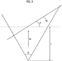
- resolution per pixel (the inverse number of pixel density) can be obtained using the imaging distance L and an inclination angle ⁇ of the surface Sp to be imaged by the following equation 3.
- Resolution mm / pixel 2 ⁇ imaging distance L mm ⁇ tan ( angle ⁇ of view/2 / the number of pixels of imaging element ) /cos ⁇
- the actual pixel density can be calculated on the basis of the number of pixels of the imaging element, the size of the imaging element, the focal length, the imaging distance L, and the inclination angle ⁇ .
- pixel density which is to be obtained in a case in which the inclination angle is larger than 0° (in a case in which the surface Sp to be imaged is imaged in a direction not orthogonal to the surface Sp to be imaged as shown in Fig. 3 ), can be calculated by multiplying pixel density, which is to be obtained in a case in which the inclination angle is 0° (in a case in which the surface Sp to be imaged is imaged in a direction orthogonal to the surface Sp to be imaged as shown in Fig. 2 ), (hereinafter, referred to as "reference pixel density”) and cos ⁇ together.
- Resolution (the inverse number of pixel density) may be calculated, and resolution, which is to be obtained in a case in which the inclination angle is larger than 0°, can be calculated by multiplying resolution, which is to be obtained in a case in which the inclination angle ⁇ is 0°, and (1/cos ⁇ ) together. Calculation using the resolution is also included in the invention.
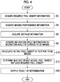
- Fig. 4 is a flowchart showing the flow of an example of imaging support processing of the first embodiment. This processing is performed according to a program stored in the storage unit 14.
- the required pixel density information and the imaging performance information are stored in the storage unit 14 in advance.
- the required pixel density information is acquired from the storage unit 14 by the required pixel density information-acquisition unit 16 (Step S2).
- the imaging performance information is acquired from the storage unit 14 on the basis of at least one of the type of a member of the structure or the type of damage to the structure by the imaging performance information-acquisition unit 18 (Step S4).
- Step S6 the distance information on a distance between the imaging device 200 and the surface to be imaged is acquired by the distance information-acquisition unit 20 (Step S6).
- the inclination angle information on the inclination angle of the surface to be imaged with respect to a direction orthogonal to the imaging direction of the imaging device 200 is acquired by the inclination angle information-acquisition unit 22 (Step S8).
- the actual pixel density of the surface to be imaged of the structure in a taken image is calculated on the basis of the imaging performance information, the distance information, and the inclination angle information by the actual pixel density-calculation unit 24 (Step S10).
- the pixel density-determination unit 26 determines whether or not the calculated actual pixel density matches the required pixel density information (Step S12). For example, the pixel density-determination unit 26 determines whether or not the actual pixel density has a value required for the recognition of cracks or crevices.
- Step S20 the result of the determination of the pixel density-determination unit 26 is output by the output unit 40 (Step S20). It is preferable that the output unit 40 displays information prompting the imaging device 200 to move in a case where it is determined that the actual pixel density does not match the required pixel density information.
- Fig. 5 is a block diagram showing an example of the configuration of an imaging support device according to a second embodiment.
- the same components as the components of the imaging support device of the first embodiment shown in Fig. 1 are denoted in Fig. 5 by the same reference numerals as the reference numerals of the components of the imaging support device of the first embodiment shown in Fig. 1 , and the description thereof will be omitted.
- the imaging support device 10 of this embodiment includes a requirement matching range-determination unit 28 that determines a requirement matching range, in which actual pixel density information matches the required pixel density information, in an imageable range of the surface to be imaged corresponding to the angle of view of the imaging device 200.
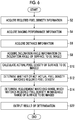
- Fig. 6 is a flowchart showing the flow of an example of imaging support processing of the second embodiment. This processing is performed according to a program stored in the storage unit 14. Since Steps S2 to S12 of Fig. 6 are the same as those of the example of imaging support processing of the first embodiment shown in Fig. 4 , the description of Steps S2 to S12 of Fig. 6 will be omitted.
- Step S14 the requirement matching range-determination unit 28 that determines a requirement matching range, in which the actual pixel density matches the required pixel density information, in an imageable range of the surface to be imaged corresponding to the angle of view of the imaging device 200.
- Step S22 the result of the determination of the pixel density-determination unit 26 and the result of the determination of the requirement matching range-determination unit 28 are output by the output unit 40.
- Fig. 7 shows a frame that shows an imageable range Ap of the imaging device 200 on a display device as an example of the output unit 40, and shows an example in which a requirement matching range Ag is shown with dots.
- a requirement mismatching range is widened in the imageable range Ap as the inclination angle ⁇ of the surface Sp to be imaged is increased.
- the invention is not particularly limited to a display example shown in Fig. 7 .
- information representing a requirement mismatching range may be displayed.
- the requirement matching range-determination unit 28 determines a requirement mismatching range, so that the requirement matching range is determined.
- the output unit 49 displays the requirement mismatching range, so that the requirement matching range is output.
- Fig. 8 is a block diagram showing an example of the configuration of an imaging support device according to a third embodiment.
- the same components as the components of the imaging support device of the second embodiment shown in Fig. 5 are denoted in Fig. 8 by the same reference numerals as the reference numerals of the components of the imaging support device of the second embodiment shown in Fig. 5 , and the description thereof will be omitted.
- the imaging support device 10 of this embodiment includes: an imaging control computing unit 32 that computes an imaging position and an imaging direction of the imaging device 200, which allow the actual pixel density to match the required pixel density information, on the basis of the current imaging position and the current imaging direction of the imaging device 200 in a case where it is determined that the actual pixel density does not match the required pixel density information; and an imaging control unit 34 that controls the imaging position and the imaging direction of the imaging device 200 on the basis of the computation results of the imaging control computing unit 32.
- Fig. 9 is a flowchart showing the flow of an example of imaging support processing of the third embodiment. This processing is performed according to a program stored in the storage unit 14. Since Steps S2 to S14 of Fig. 9 are the same as those of the example of imaging support processing of the second embodiment shown in Fig. 6 , the description of Steps S2 to S14 of Fig. 9 will be omitted.
- Step S16 an imaging position and an imaging direction of the imaging device 200, which allow the actual pixel density to match the required pixel density information, are computed by the imaging control computing unit 32 on the basis of the current imaging position and the current imaging direction of the imaging device 200 in a case where it is determined that the actual pixel density does not match the required pixel density information.
- Step S18 the imaging position and the imaging direction of the imaging device 200 are controlled on the basis of the computation results of the imaging control computing unit 32 by the imaging control unit 34.
- An example of an imaging support device which is used to inspect a structure built as social infrastructure, will be described below.
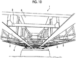
- Fig. 10 is a diagram showing the appearance of a bridge that is an example of a structure, and is a perspective view of the bridge seen from below.
- the bridge 1 shown in Fig. 10 includes main girders 2, cross beams 3, cross frames 4, and lateral frames 5; and the main girders 2, the cross beams 3, the cross frames 4, and the lateral frames 5 are connected to each other by bolts, rivets, or welding. Further, deck slabs 6 on which vehicles and the like travel are installed on the main girders 2 and the like.
- the deck slab 6 is generally formed of a concrete member.
- the main girder 2 is a member that is provided between abutments or piers and supports the load of vehicles and the like present on the deck slab 6.
- the cross beams 3 are members connecting the main girders 2 so that a load is supported by the plurality of main girders 2.
- the cross frame 4 and the lateral frame 5 are members that connect the main girders 2 to resist the lateral load of wind and earthquake.
- the bridge 1 includes concrete members and steel members as members to be inspected. That is, the bridge 1 includes members in which cracks are generated as damage to be recognized and members in which crevices are generated as damage to be recognized.
- the invention can also be applied to a case in which a structure including only one of concrete members and steel members, that is, a structure including only one of members in which cracks are generated and members in which crevices are generated is imaged.
- the "structure” of the invention is not limited to a bridge.
- the "structure” of the invention may be a road, a tunnel, a dam, and a building.
- the "structure” of the invention is not limited to an artificial structure and may be a natural structure.
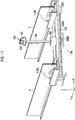
- Fig. 11 is a perspective view showing the appearance of a robot apparatus 100 including the imaging device 200, and shows a state in which the robot apparatus 100 is installed between the main girders 2 of the bridge 1. Further, Fig. 12 is a cross-sectional view of main parts of the robot apparatus 100 shown in Fig. 11 .
- the robot apparatus 100 includes the imaging device 200, and controls the position (which is an actual imaging position) of the imaging device 200 in a three-dimensional space and controls the imaging direction (which is an actual imaging direction) of the imaging device 200.
- the robot apparatus 100 includes a main frame 102, a vertical telescopic arm 104, a housing 106 in which drive units, various control units, and the like for the vertical telescopic arm 104 are provided, an X-direction drive unit 108 ( Fig. 14 ) that moves the housing 106 in a longitudinal direction of the main frame 102 (a direction orthogonal to the longitudinal direction of the main girder 2) (X direction), a Y-direction drive unit 110 ( Fig. 14 ) that moves the entire robot apparatus 100 in the longitudinal direction of the main girder 2 (Y direction), and a Z-direction drive unit 112 ( Fig. 14 ) that makes the vertical telescopic arm 104 elongate and contract in a vertical direction (Z direction).
- X-direction drive unit 108 that moves the housing 106 in a longitudinal direction of the main frame 102 (a direction orthogonal to the longitudinal direction of the main girder 2) (X direction)
- a Y-direction drive unit 110 Fig
- the X-direction drive unit 108 includes a ball screw 108A that is provided in the longitudinal direction of the main frame 102 (X direction), a ball nut 108B that is provided in the housing 106, and a motor 108C that rotates the ball screw 108A; and rotates the ball screw 108A in a normal direction or a reverse direction by the motor 108C to move the housing 106 in the X direction.
- the Y-direction drive unit 110 includes tires 110A and 110B that are provided at both ends of the main frame 102 and motors (not shown) that are provided in the tires 110A and 110B; and drives the tires 110A and 110B by the motors to move the entire robot apparatus 100 in the Y direction.
- the robot apparatus 100 is installed in an aspect in which the tires 110A and 110B provided at both ends of the main frame 102 are placed on lower flanges of the two main girders 2 and are disposed so that the main girders 2 are positioned between the tires 110A and 110B. Accordingly, the robot apparatus 100 can move (be self-propelled) along the main girders 2 while being suspended from the lower flanges of the main girders 2. Further, although not shown, the main frame 102 is adapted so that the length of the main frame 102 can be adjusted in accordance with an interval between the main girders 2.
- the vertical telescopic arm 104 is provided in the housing 106 of the robot apparatus 100, and is moved in the X direction and the Y direction together with the housing 106. Further, the vertical telescopic arm 104 is made to elongate and contract in the Z direction by the Z-direction drive unit 112 ( Fig. 14 ) that is provided in the housing 106.
- a camera installation part 104A is provided at the distal end of the vertical telescopic arm 104 as shown in Fig. 13 , and a twin-lens camera 202, which can be rotated in a pan direction and a tilt direction by a pan/tilt mechanism 120, is installed on the camera installation part 104A.
- the twin-lens camera 202 includes a first imaging unit 202A and a second imaging unit 202B that take two parallax images (stereoscopic images) having different parallax; functions as a part of a first space information-acquisition unit that acquires first space information of the structure (bridge 1) corresponding to the imaging range of the twin-lens camera 202 in a local coordinate system (camera coordinate system) based on the twin-lens camera 202; and acquires at least one image of the two images, which are to be taken, as an "inspection image" to be attached to an inspection record.
- first space information-acquisition unit that acquires first space information of the structure (bridge 1) corresponding to the imaging range of the twin-lens camera 202 in a local coordinate system (camera coordinate system) based on the twin-lens camera 202; and acquires at least one image of the two images, which are to be taken, as an "inspection image" to be attached to an inspection record.
- twin-lens camera 202 is rotated about a pan axis P coaxial with the vertical telescopic arm 104 or is rotated about a tilt axis T parallel to a horizontal direction by the pan/tilt mechanism 120 to which a driving force is applied from a pan/tilt drive unit 206 ( Fig. 14 ). Accordingly, the twin-lens camera 202 can take images in any posture (take images in any imaging direction).
- An optical axis L 1 of the first imaging unit 202A of the twin-lens camera 202 of this embodiment and an optical axis L 2 of the second imaging unit 202B are parallel to each other. Further, the pan axis P is orthogonal to the tilt axis T. Furthermore, the base length of the twin-lens camera 202 (that is, an installation interval between the first imaging unit 202A and the second imaging unit 202B) is already known.
- a camera coordinate system which is based on the twin-lens camera 202, uses an intersection point between the pan axis P and the tilt axis T as an origin Or; and the direction of the tilt axis T is referred to as an X direction (Xr in Fig. 13 ), the direction of the pan axis P is referred to as a Z direction (Zr in Fig. 13 ), and a direction orthogonal to an X direction and a Z direction is referred to as a Y direction (Yr in Fig. 13 ).
- the position (which is an "actual imaging position") of the twin-lens camera 202 can be detected using the moving distances of the robot apparatus 100 in the X direction and the Y direction and the moving distance of the vertical telescopic arm 104 in the Z direction with respect to the origin of a bridge coordinate system. Further, the imaging direction of the twin-lens camera 202 can be detected using the pan angle ⁇ and the tilt angle ⁇ of the pan/tilt mechanism or can be detected by a direction sensor (not shown) mounted on the twin-lens camera 202.
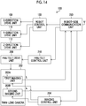
- Fig. 14 is a block diagram of an example of the robot apparatus 100.
- the robot apparatus 100 shown in Fig. 14 includes a robot control unit 130, the X-direction drive unit 108, the Y-direction drive unit 110, the Z-direction drive unit 112, the twin-lens camera 202 (imaging device 200), an imaging control unit 204, a pan/tilt control unit 210, a pan/tilt drive unit 206, and a robot-side communication unit 230.
- the robot-side communication unit 230 performs two-way radio communication between the imaging support device 10 and itself; receives various commands, such as a movement command for controlling the movement of the robot apparatus 100, a pan/tilt command for controlling the pan/tilt mechanism 120, and an imaging command for controlling the twin-lens camera 202, which are transmitted from the imaging support device 10; and outputs the received commands to the corresponding control units, respectively.
- various commands such as a movement command for controlling the movement of the robot apparatus 100, a pan/tilt command for controlling the pan/tilt mechanism 120, and an imaging command for controlling the twin-lens camera 202, which are transmitted from the imaging support device 10; and outputs the received commands to the corresponding control units, respectively.
- the robot control unit 130 controls the X-direction drive unit 108, the Y-direction drive unit 110, and the Z-direction drive unit 112 on the basis of a movement command, which is input from the robot-side communication unit 230, to make the robot apparatus 100 move in the X direction and the Y direction and to make the vertical telescopic arm 104 elongate and contract in the Z direction (see Fig. 11 ).
- the pan/tilt control unit 210 makes the pan/tilt mechanism 120 be operated in the pan direction and the tilt direction by the pan/tilt drive unit 206 on the basis of a pan/tilt command, which is input from the robot-side communication unit 230, to pan and tilt the twin-lens camera 202 in a desired direction (see Fig. 13 ).
- the imaging control unit 204 makes the first and second imaging units 202A and 202B of the twin-lens camera 202 take live-view images or inspection images on the basis of an imaging command that is input from the robot-side communication unit 230.
- the "imaging device” of the invention is not limited to a digital camera mounted on the robot apparatus.
- the “imaging device” of the invention may be, for example, a digital camera mounted on a drone (flying device) and a digital camera carried by a person.
- image of the invention is not limited to a still image.
- image of the invention may be a moving image.
- the imaging device 200 includes the imaging element and the imaging lens.
- Fig. 15 is a block diagram showing an example of an imaging support system using the imaging support device of the invention. A case in which the imaging support device 10 of the Fig. 15 is applied as a terminal device for controlling the robot apparatus 100 shown in Figs. 11 to 14 will be described in this embodiment.
- the imaging support device 10 of this embodiment includes an external input/output unit 62 that inputs and outputs various types of information to and from a database 50, a display unit 63 (which is one form of an "output unit") that displays information to a user, a sound output unit 64 that outputs sound to the user, an instruction input unit 65 that receives an instruction input from the user, and a central processing unit (CPU) 70 that controls the respective units of the imaging support device 10 according to a program stored in the storage unit 14.
- CPU central processing unit
- the radio communication unit 12 of this embodiment can perform radio communication between the robot apparatus 100 and a reference device 300.
- the external input/output unit 62 includes a device that can communicate with the database 50 through a network.
- a device which inputs and outputs information to and from an external storage device, such as a memory card, of the imaging support device 10, may be used as the external input/output unit 62.
- the external input/output unit 62 of this embodiment acquires drawing information of a structure from the database 50. That is, the external input/output unit 62 of this embodiment is one form of a "drawing information-acquisition unit".
- the drawing information is, for example, CAD (computer aided design) drawing data.
- the drawing information may be non-CAD drawing data that is not created with CAD.
- the display unit 63 is formed of, for example, a liquid crystal display (LCD).
- LCD liquid crystal display
- the sound output unit 64 is formed of, for example, a speaker.
- the instruction input unit 65 is formed of, for example, a touch panel.
- the instruction input unit 65 may be formed of a keyboard and a mouse.
- Other input devices may be used as the instruction input unit 65.
- a voice input device may be used as the instruction input unit 65.
- the CPU 70 of this embodiment includes: an imaging point specification unit 72 that specifies an imaging point of the structure on the basis of at least the drawing information; an imaging planning unit 74 that determines a scheduled imaging position of the imaging device 200 at each imaging of the structure and a scheduled imaging direction of the imaging device 200 at each imaging of the structure on the basis of at least the specified imaging point and generates imaging plan information representing the scheduled imaging position at each imaging and the scheduled imaging direction at each imaging; an actual imaging information-acquisition unit 76 that acquires actual imaging position information of the imaging device 200 at each imaging of the structure and actual imaging direction information of the imaging device 200 at each imaging of the structure; an imaging support information-generation unit 78 that generates imaging support information for combining the imaging plan information with the drawing information and allowing the display unit 63 to display the combined information; an image quality-determination unit 82 that determines whether or not the actual image quality of a taken image obtained by the imaging device 200 matches required image quality; an imaging range-determination unit 84 that determines whether or not an imaging range is appropriate; an imaging completion-determination
- the image quality control unit 90 includes the respective units, which are denoted by reference numerals 20 to 34, (the distance information-acquisition unit 20, the inclination angle information-acquisition unit 22, the actual pixel density-calculation unit 24, the pixel density-determination unit 26, the requirement matching range-determination unit 28, the imaging control computing unit 32, and the imaging control unit 34) of the imaging support device 10 of the third embodiment shown in Fig. 8 .
- the image quality-determination unit 82 of this embodiment determines image quality using the actual pixel density-calculation unit 24, the pixel density-determination unit 26, and the requirement matching range-determination unit 28 of the image quality control unit 90.
- Fig. 16 is a flowchart showing the flow of an example of imaging support processing of the imaging support device of Fig. 15 .
- This processing is performed by the CPU 70 according to a program stored in the storage unit 14.
- a case in which the bridge 1 of Fig. 10 is imaged as a structure to be inspected will be described below by way of example.
- the drawing information of the structure and information related to the imaging point of the structure are acquired from the database 50 by the external input/output unit 62 (Step S102).
- the CAD drawing data of the bridge 1 is acquired as the drawing information.
- the imaging point of the structure is specified on the basis of the drawing information and the information related to the imaging point by the imaging point specification unit 72 (Step S104).
- the imaging point is specified on the basis of the drawing information and the information related to the imaging point by the imaging point specification unit 72 (Step S104).
- the imaging point is specified as the imaging point.
- image quality information required for the taken image, the imaging performance information of the imaging device 200, and moving range information representing a range where the imaging device 200 can be moved or a range where the imaging device 200 cannot be moved are acquired from the database 50 by the external input/output unit 62 (Step S106).
- Image quality information corresponding to the width of "crack", which requires the highest image quality, of damage to the deck slab 6 made of concrete is acquired in this embodiment.
- the pixel density of the taken image required for the exposed surface (which is the surface to be imaged) of the deck slab 6 (required pixel density) is acquired as the image quality information.
- an overlap width required for the taken image (hereinafter, referred to as a "required overlap width”) is acquired in this embodiment.
- the required overlap width is the width of an overlapping portion between one taken image and another taken image adjacent to the taken image. In other words, the required overlap width is the width of an overlapping portion between adjacent imaging ranges.
- the imaging plan information which includes the imaging position information and the imaging direction information of the imaging device 200 at each imaging and the imaging range information of the structure, is generated by the imaging planning unit 74 on the basis of the imaging point that is specified in Step S104 and the image quality information, the imaging performance information, and the moving range information that are acquired in Step S106 (Step S108).
- the imaging plan information is stored in the storage unit 14.
- the imaging support device 10 can communicate with the robot apparatus 100, the imaging device 200, and the reference device 300 by radio in an inspection site.
- the imaging support device 10 may have access to the database 50 in the inspection site, but does not need to have access to the database 50 in a case in which information required for Steps S110 to S132 (for example, the drawing information and the imaging plan information) is stored in the storage unit 14 in advance before Step S110.
- the imaging support information-generation unit 78 combines the imaging plan information with the drawing information and allows the display unit 63 to display the combined information (Step S110). For example, in a case in which the deck slab 6 is imaged in panel and one panel is split into twelve pieces and each of the twelve pieces is imaged, the imaging support information-generation unit 78 combines the imaging position information and the imaging range information with the drawing information at each of a total of twelve times of split imaging.
- the imaging control unit 34 of the image quality control unit 90 determines whether or not one time of imaging is performed by the imaging device 200 (Step S112).
- the actual imaging position information, the actual imaging direction information, and actual imaging range information of the imaging device 200 are acquired by the actual imaging information-acquisition unit 76 (Step S114).
- the current position of the imaging device 200 is measured by the reference device 300 (for example, a total station) of which the absolute position is known.
- the imaging device 200 transmits the taken image to the imaging support device 10 through radio communication.
- the imaging support device 10 makes the image, which is received from the imaging device 200 through radio communication, and the actual imaging position information, which is received from the reference device 300 through radio communication, be associated with each other and stores the image and the actual imaging position information in the storage unit 14.
- the imaging support device 10 may record the image and the actual imaging position information in an external device (not shown) instead of storing the image and the actual imaging position information in the storage unit 14.
- an imaging instruction and the actual imaging position information (which is information received from the reference device 300 through radio communication) are transmitted to the imaging device 200 from the imaging support device 10 through radio communication, and an image and the actual imaging position information may be stored in association with each other by the imaging device 200.
- the reference device 300 measures the reference position of the deck slab 6 of the bridge 1, and can calculate the actual imaging position information of which the origin is the reference position of the deck slab 6.
- the actual imaging information-acquisition unit 76 can acquire the actual imaging range information on the basis of the actual imaging position information and the actual imaging direction information. In a case in which the imaging direction of the imaging device 200 is constant, the actual imaging information-acquisition unit 76 can acquire the actual imaging range information while using only the actual imaging position information as a parameter.
- Step S114 required information of the information acquired in Step S114 (actual imaging information including the actual imaging position information, the actual imaging direction information, and the actual imaging range information) is combined with the drawing information by the imaging support information-generation unit 78 (Step S116).
- the actual pixel density of the taken image is calculated by the actual pixel density-calculation unit 24 of the image quality control unit 90 (Step S118), and the imaging range-determination unit 84 calculates the overlap width of an actual imaging range (Step S120) and determines whether or not the actual pixel density matches the required pixel density and the overlap width of the taken image matches the required overlap width (Step S122).
- Step S124 If it is determined that the pixel density of the taken image does not match the required pixel density or the overlap width of the taken image does not match the required overlap width (If the result of the determination in Step S122 is "NO"), warning information is output to the display unit 63 (Step S124) and processing returns to Step S112. That is, the display unit 63 is allowed to display warning information and prompts a user to take an image again.
- Step S126 determines whether or not all of a plurality of times of imaging of the imaging point end. If it is determined that the imaging is completed (If the result of the determination in Step S126 is "YES"), the completion of the imaging is displayed (Step S132) and this processing ends.
- Step S112 determines whether or not the incomplete imaging of the imaging point is present and a user has a mind to complete imaging. If it is determined that the imaging is not completed and a user has a mind to complete imaging (If the result of the determination in Step S128 is "YES"), the incompletion of the imaging is displayed (Step S130).
- the display unit 63 in a case in which an imaging range, which is not yet imaged, is present at the imaging point (in this embodiment, the entire exposed surface of the deck slab 6 of the bridge 1) and a distance between the imaging position of the incomplete imaging and the imaging device 200 exceeds a threshold value, the display unit 63 is allowed to display imaging incompletion information.
- the display unit 63 may be allowed to display imaging incompletion information. In a case in which a stop instruction is input to the imaging device 200 in a state in which the imaging is incomplete, the display unit 63 may be allowed to display an imaging incompletion display.
Applications Claiming Priority (2)
| Application Number | Priority Date | Filing Date | Title |
|---|---|---|---|
| JP2016010710 | 2016-01-22 | ||
| PCT/JP2017/000503 WO2017126368A1 (fr) | 2016-01-22 | 2017-01-10 | Dispositif de prise en charge d'imagerie et procédé de prise en charge d'imagerie |
Publications (3)
| Publication Number | Publication Date |
|---|---|
| EP3407590A1 true EP3407590A1 (fr) | 2018-11-28 |
| EP3407590A4 EP3407590A4 (fr) | 2019-02-13 |
| EP3407590B1 EP3407590B1 (fr) | 2021-02-24 |
Family
ID=59361582
Family Applications (1)
| Application Number | Title | Priority Date | Filing Date |
|---|---|---|---|
| EP17741248.3A Active EP3407590B1 (fr) | 2016-01-22 | 2017-01-10 | Dispositif de prise en charge d'imagerie et procédé de prise en charge d'imagerie |
Country Status (5)
| Country | Link |
|---|---|
| US (1) | US10739274B2 (fr) |
| EP (1) | EP3407590B1 (fr) |
| JP (1) | JP6507268B2 (fr) |
| CN (1) | CN108476282B (fr) |
| WO (1) | WO2017126368A1 (fr) |
Families Citing this family (8)
| Publication number | Priority date | Publication date | Assignee | Title |
|---|---|---|---|---|
| JP6891071B2 (ja) * | 2017-08-07 | 2021-06-18 | キヤノン株式会社 | 情報処理装置、撮像システム、撮像方法及びプログラム |
| JP2020027574A (ja) * | 2018-08-17 | 2020-02-20 | 株式会社東芝 | 自律移動装置、方法及び3次元モデリングシステム |
| JP7289626B2 (ja) * | 2018-10-30 | 2023-06-12 | キヤノン株式会社 | 情報処理装置、その制御方法、プログラム、及び記憶媒体 |
| JP7337557B2 (ja) * | 2019-06-14 | 2023-09-04 | キヤノン株式会社 | 情報処理装置、システム、情報処理方法及びプログラム |
| CN110514664B (zh) * | 2019-08-20 | 2022-08-12 | 北京信息科技大学 | 一种筒子纱纱杆定位检测机器人及方法 |
| US20220001761A1 (en) * | 2020-07-02 | 2022-01-06 | Abb Schweiz Ag | Systems and Methods for Electric Vehicle Charging Using Image Capturing Devices |
| CN112197746B (zh) * | 2020-09-16 | 2022-06-21 | 上海建工四建集团有限公司 | 一种清水砖墙表面风化程度智能检测设备及检测方法 |
| US20230242279A1 (en) * | 2022-02-03 | 2023-08-03 | The Boeing Company | Automated method and system for aircraft inspection with data validation |
Family Cites Families (19)
| Publication number | Priority date | Publication date | Assignee | Title |
|---|---|---|---|---|
| JPH05334480A (ja) * | 1992-06-04 | 1993-12-17 | Olympus Optical Co Ltd | バーコード読取装置 |
| JP4626007B2 (ja) * | 1999-06-14 | 2011-02-02 | 株式会社ニコン | 画像処理方法、画像処理プログラムを記録した機械読み取り可能な記録媒体、および画像処理装置 |
| JP2003015218A (ja) * | 2001-07-03 | 2003-01-15 | Ricoh Co Ltd | 投影型表示装置 |
| JP4759426B2 (ja) | 2005-03-30 | 2011-08-31 | Hoya株式会社 | 撮影装置 |
| WO2007097431A1 (fr) * | 2006-02-23 | 2007-08-30 | Matsushita Electric Industrial Co., Ltd. | dispositif de correction d'images, procede, programme, circuit integre et systeme |
| JP2007280282A (ja) | 2006-04-11 | 2007-10-25 | Oriental Consultants:Kk | 構造物の点検記録システム |
| JP4954006B2 (ja) * | 2007-09-28 | 2012-06-13 | 三洋電機株式会社 | クラック幅計測システム、操作装置、クラック幅計測方法、及びクラック幅計測プログラム |
| JP5218849B2 (ja) * | 2009-03-13 | 2013-06-26 | 株式会社コンステック | 欠陥検査装置 |
| JP5591570B2 (ja) * | 2010-03-23 | 2014-09-17 | オリンパス株式会社 | 画像処理装置、画像処理方法及びプログラム |
| US8933927B2 (en) * | 2010-09-02 | 2015-01-13 | Samsung Electronics Co., Ltd. | Display system with image conversion mechanism and method of operation thereof |
| JP5644461B2 (ja) * | 2010-12-14 | 2014-12-24 | 富士ゼロックス株式会社 | 画像処理装置及びプログラム |
| US8331670B2 (en) * | 2011-03-22 | 2012-12-11 | Konica Minolta Laboratory U.S.A., Inc. | Method of detection document alteration by comparing characters using shape features of characters |
| US9696897B2 (en) * | 2011-10-19 | 2017-07-04 | The Regents Of The University Of California | Image-based measurement tools |
| CN102692347A (zh) * | 2012-05-08 | 2012-09-26 | 浙江工业大学 | 疲劳裂纹扩展试验摄像头自动调整图像采集装置及方法 |
| US10783615B2 (en) * | 2013-03-13 | 2020-09-22 | Kofax, Inc. | Content-based object detection, 3D reconstruction, and data extraction from digital images |
| CA2951960A1 (fr) * | 2014-06-25 | 2015-12-30 | Retailmenot, Inc. | Appareil et procede pour distributeur mobile pour flux de traitement de remboursement d'offre |
| CN104469344B (zh) * | 2014-12-03 | 2017-03-01 | 北京智谷技术服务有限公司 | 光场显示控制方法和装置、光场显示设备 |
| US10255521B2 (en) * | 2016-12-12 | 2019-04-09 | Jack Cooper Logistics, LLC | System, method, and apparatus for detection of damages on surfaces |
| US10685455B2 (en) * | 2018-05-02 | 2020-06-16 | Stable Auto Corporation | Method and system for automated vehicle charging |
-
2017
- 2017-01-10 EP EP17741248.3A patent/EP3407590B1/fr active Active
- 2017-01-10 WO PCT/JP2017/000503 patent/WO2017126368A1/fr active Application Filing
- 2017-01-10 JP JP2017562520A patent/JP6507268B2/ja active Active
- 2017-01-10 CN CN201780006368.0A patent/CN108476282B/zh active Active
-
2018
- 2018-06-22 US US16/015,267 patent/US10739274B2/en active Active
Also Published As
| Publication number | Publication date |
|---|---|
| WO2017126368A1 (fr) | 2017-07-27 |
| US20180299387A1 (en) | 2018-10-18 |
| JPWO2017126368A1 (ja) | 2018-11-29 |
| CN108476282B (zh) | 2020-07-17 |
| EP3407590A4 (fr) | 2019-02-13 |
| JP6507268B2 (ja) | 2019-04-24 |
| EP3407590B1 (fr) | 2021-02-24 |
| CN108476282A (zh) | 2018-08-31 |
| US10739274B2 (en) | 2020-08-11 |
Similar Documents
| Publication | Publication Date | Title |
|---|---|---|
| US10739274B2 (en) | Imaging support device and imaging support method | |
| US10762619B2 (en) | Imaging support device and imaging support method | |
| US10365090B2 (en) | Imaging device and imaging method | |
| US10748269B2 (en) | Structure member specification device and structure member specification method | |
| US10877475B2 (en) | Robot device and method of controlling movement of robot device | |
| EP3842751A1 (fr) | Système et procédé de génération de carte haute définition sur la base d'une caméra | |
| US11514681B2 (en) | System and method to facilitate calibration of sensors in a vehicle | |
| US10951821B2 (en) | Imaging control device, imaging system, and imaging control method | |
| CN112445204B (zh) | 工地中的物体移动导航方法、装置和计算机设备 | |
| KR20200083301A (ko) | 이동하는 오브젝트 센서의 정렬을 교정하기 위한 방법 | |
| US11686053B2 (en) | Three-dimensional bridge deck finisher | |
| US11107240B2 (en) | Self position estimation device, self position estimation method, program, and image processing device | |
| US10742874B2 (en) | Imaging plan generation device, imaging plan generation method, and program | |
| US20150330054A1 (en) | Optical Sensing a Distance from a Range Sensing Apparatus and Method | |
| JP2021124377A (ja) | キャリブレーション判定結果提示装置、キャリブレーション判定結果提示方法及びプログラム | |
| KR101966396B1 (ko) | 위치 판단 시스템, 방법 및 컴퓨터 판독 가능한 기록매체 | |
| JP4268404B2 (ja) | 移動体の自己位置計測方法 | |
| Dehkordi | Health Monitoring of Structures and Damage Detection Using Vision-Based Methods and Artificial Intelligence | |
| CN117999589A (zh) | 确定停车空间品质值的方法及设备 | |
| CN117857925A (zh) | 基于igv的砼预制构件图像采集方法及相关设备 | |
| CN115773745A (zh) | 无人集卡对位方法、装置、设备及可读存储介质 | |
| CN117554936A (zh) | 一种雷达标定方法、系统、装置及存储介质 | |
| JP2018031588A (ja) | 観察装置および観察方法 |
Legal Events
| Date | Code | Title | Description |
|---|---|---|---|
| STAA | Information on the status of an ep patent application or granted ep patent |
Free format text: STATUS: THE INTERNATIONAL PUBLICATION HAS BEEN MADE |
|
| PUAI | Public reference made under article 153(3) epc to a published international application that has entered the european phase |
Free format text: ORIGINAL CODE: 0009012 |
|
| STAA | Information on the status of an ep patent application or granted ep patent |
Free format text: STATUS: REQUEST FOR EXAMINATION WAS MADE |
|
| 17P | Request for examination filed |
Effective date: 20180622 |
|
| AK | Designated contracting states |
Kind code of ref document: A1 Designated state(s): AL AT BE BG CH CY CZ DE DK EE ES FI FR GB GR HR HU IE IS IT LI LT LU LV MC MK MT NL NO PL PT RO RS SE SI SK SM TR |
|
| AX | Request for extension of the european patent |
Extension state: BA ME |
|
| A4 | Supplementary search report drawn up and despatched |
Effective date: 20190111 |
|
| RIC1 | Information provided on ipc code assigned before grant |
Ipc: G01M 5/00 20060101ALI20190107BHEP Ipc: G01N 21/88 20060101ALI20190107BHEP Ipc: H04N 5/225 20060101AFI20190107BHEP Ipc: G03B 15/00 20060101ALI20190107BHEP |
|
| DAV | Request for validation of the european patent (deleted) | ||
| DAX | Request for extension of the european patent (deleted) | ||
| REG | Reference to a national code |
Ref country code: DE Ref legal event code: R079 Ref document number: 602017033287 Country of ref document: DE Free format text: PREVIOUS MAIN CLASS: H04N0005225000 Ipc: G01C0009000000 |
|
| GRAP | Despatch of communication of intention to grant a patent |
Free format text: ORIGINAL CODE: EPIDOSNIGR1 |
|
| RIC1 | Information provided on ipc code assigned before grant |
Ipc: G01N 21/95 20060101ALI20200629BHEP Ipc: H04N 7/18 20060101ALI20200629BHEP Ipc: G01N 21/88 20060101ALI20200629BHEP Ipc: G03B 15/00 20060101ALI20200629BHEP Ipc: H04N 5/232 20060101ALI20200629BHEP Ipc: G03B 17/56 20060101ALI20200629BHEP Ipc: G01C 9/00 20060101AFI20200629BHEP Ipc: G01M 5/00 20060101ALI20200629BHEP |
|
| STAA | Information on the status of an ep patent application or granted ep patent |
Free format text: STATUS: GRANT OF PATENT IS INTENDED |
|
| INTG | Intention to grant announced |
Effective date: 20200806 |
|
| RIN1 | Information on inventor provided before grant (corrected) |
Inventor name: NONAKA, SHUNICHIRO |
|
| GRAS | Grant fee paid |
Free format text: ORIGINAL CODE: EPIDOSNIGR3 |
|
| GRAA | (expected) grant |
Free format text: ORIGINAL CODE: 0009210 |
|
| STAA | Information on the status of an ep patent application or granted ep patent |
Free format text: STATUS: THE PATENT HAS BEEN GRANTED |
|
| AK | Designated contracting states |
Kind code of ref document: B1 Designated state(s): AL AT BE BG CH CY CZ DE DK EE ES FI FR GB GR HR HU IE IS IT LI LT LU LV MC MK MT NL NO PL PT RO RS SE SI SK SM TR |
|
| REG | Reference to a national code |
Ref country code: CH Ref legal event code: EP |
|
| REG | Reference to a national code |
Ref country code: DE Ref legal event code: R096 Ref document number: 602017033287 Country of ref document: DE |
|
| REG | Reference to a national code |
Ref country code: AT Ref legal event code: REF Ref document number: 1365040 Country of ref document: AT Kind code of ref document: T Effective date: 20210315 |
|
| REG | Reference to a national code |
Ref country code: IE Ref legal event code: FG4D |
|
| RAP4 | Party data changed (patent owner data changed or rights of a patent transferred) |
Owner name: FUJIFILM CORPORATION |
|
| REG | Reference to a national code |
Ref country code: LT Ref legal event code: MG9D |
|
| REG | Reference to a national code |
Ref country code: NL Ref legal event code: MP Effective date: 20210224 |
|
| PG25 | Lapsed in a contracting state [announced via postgrant information from national office to epo] |
Ref country code: LT Free format text: LAPSE BECAUSE OF FAILURE TO SUBMIT A TRANSLATION OF THE DESCRIPTION OR TO PAY THE FEE WITHIN THE PRESCRIBED TIME-LIMIT Effective date: 20210224 Ref country code: BG Free format text: LAPSE BECAUSE OF FAILURE TO SUBMIT A TRANSLATION OF THE DESCRIPTION OR TO PAY THE FEE WITHIN THE PRESCRIBED TIME-LIMIT Effective date: 20210524 Ref country code: FI Free format text: LAPSE BECAUSE OF FAILURE TO SUBMIT A TRANSLATION OF THE DESCRIPTION OR TO PAY THE FEE WITHIN THE PRESCRIBED TIME-LIMIT Effective date: 20210224 Ref country code: HR Free format text: LAPSE BECAUSE OF FAILURE TO SUBMIT A TRANSLATION OF THE DESCRIPTION OR TO PAY THE FEE WITHIN THE PRESCRIBED TIME-LIMIT Effective date: 20210224 Ref country code: GR Free format text: LAPSE BECAUSE OF FAILURE TO SUBMIT A TRANSLATION OF THE DESCRIPTION OR TO PAY THE FEE WITHIN THE PRESCRIBED TIME-LIMIT Effective date: 20210525 Ref country code: NO Free format text: LAPSE BECAUSE OF FAILURE TO SUBMIT A TRANSLATION OF THE DESCRIPTION OR TO PAY THE FEE WITHIN THE PRESCRIBED TIME-LIMIT Effective date: 20210524 Ref country code: PT Free format text: LAPSE BECAUSE OF FAILURE TO SUBMIT A TRANSLATION OF THE DESCRIPTION OR TO PAY THE FEE WITHIN THE PRESCRIBED TIME-LIMIT Effective date: 20210624 |
|
| REG | Reference to a national code |
Ref country code: AT Ref legal event code: MK05 Ref document number: 1365040 Country of ref document: AT Kind code of ref document: T Effective date: 20210224 |
|
| PG25 | Lapsed in a contracting state [announced via postgrant information from national office to epo] |
Ref country code: SE Free format text: LAPSE BECAUSE OF FAILURE TO SUBMIT A TRANSLATION OF THE DESCRIPTION OR TO PAY THE FEE WITHIN THE PRESCRIBED TIME-LIMIT Effective date: 20210224 Ref country code: LV Free format text: LAPSE BECAUSE OF FAILURE TO SUBMIT A TRANSLATION OF THE DESCRIPTION OR TO PAY THE FEE WITHIN THE PRESCRIBED TIME-LIMIT Effective date: 20210224 Ref country code: RS Free format text: LAPSE BECAUSE OF FAILURE TO SUBMIT A TRANSLATION OF THE DESCRIPTION OR TO PAY THE FEE WITHIN THE PRESCRIBED TIME-LIMIT Effective date: 20210224 Ref country code: NL Free format text: LAPSE BECAUSE OF FAILURE TO SUBMIT A TRANSLATION OF THE DESCRIPTION OR TO PAY THE FEE WITHIN THE PRESCRIBED TIME-LIMIT Effective date: 20210224 Ref country code: PL Free format text: LAPSE BECAUSE OF FAILURE TO SUBMIT A TRANSLATION OF THE DESCRIPTION OR TO PAY THE FEE WITHIN THE PRESCRIBED TIME-LIMIT Effective date: 20210224 |
|
| PG25 | Lapsed in a contracting state [announced via postgrant information from national office to epo] |
Ref country code: IS Free format text: LAPSE BECAUSE OF FAILURE TO SUBMIT A TRANSLATION OF THE DESCRIPTION OR TO PAY THE FEE WITHIN THE PRESCRIBED TIME-LIMIT Effective date: 20210624 |
|
| PG25 | Lapsed in a contracting state [announced via postgrant information from national office to epo] |
Ref country code: AT Free format text: LAPSE BECAUSE OF FAILURE TO SUBMIT A TRANSLATION OF THE DESCRIPTION OR TO PAY THE FEE WITHIN THE PRESCRIBED TIME-LIMIT Effective date: 20210224 Ref country code: SM Free format text: LAPSE BECAUSE OF FAILURE TO SUBMIT A TRANSLATION OF THE DESCRIPTION OR TO PAY THE FEE WITHIN THE PRESCRIBED TIME-LIMIT Effective date: 20210224 Ref country code: EE Free format text: LAPSE BECAUSE OF FAILURE TO SUBMIT A TRANSLATION OF THE DESCRIPTION OR TO PAY THE FEE WITHIN THE PRESCRIBED TIME-LIMIT Effective date: 20210224 Ref country code: CZ Free format text: LAPSE BECAUSE OF FAILURE TO SUBMIT A TRANSLATION OF THE DESCRIPTION OR TO PAY THE FEE WITHIN THE PRESCRIBED TIME-LIMIT Effective date: 20210224 |
|
| REG | Reference to a national code |
Ref country code: DE Ref legal event code: R097 Ref document number: 602017033287 Country of ref document: DE |
|
| PG25 | Lapsed in a contracting state [announced via postgrant information from national office to epo] |
Ref country code: RO Free format text: LAPSE BECAUSE OF FAILURE TO SUBMIT A TRANSLATION OF THE DESCRIPTION OR TO PAY THE FEE WITHIN THE PRESCRIBED TIME-LIMIT Effective date: 20210224 Ref country code: DK Free format text: LAPSE BECAUSE OF FAILURE TO SUBMIT A TRANSLATION OF THE DESCRIPTION OR TO PAY THE FEE WITHIN THE PRESCRIBED TIME-LIMIT Effective date: 20210224 Ref country code: SK Free format text: LAPSE BECAUSE OF FAILURE TO SUBMIT A TRANSLATION OF THE DESCRIPTION OR TO PAY THE FEE WITHIN THE PRESCRIBED TIME-LIMIT Effective date: 20210224 |
|
| PLBE | No opposition filed within time limit |
Free format text: ORIGINAL CODE: 0009261 |
|
| STAA | Information on the status of an ep patent application or granted ep patent |
Free format text: STATUS: NO OPPOSITION FILED WITHIN TIME LIMIT |
|
| PG25 | Lapsed in a contracting state [announced via postgrant information from national office to epo] |
Ref country code: ES Free format text: LAPSE BECAUSE OF FAILURE TO SUBMIT A TRANSLATION OF THE DESCRIPTION OR TO PAY THE FEE WITHIN THE PRESCRIBED TIME-LIMIT Effective date: 20210224 Ref country code: AL Free format text: LAPSE BECAUSE OF FAILURE TO SUBMIT A TRANSLATION OF THE DESCRIPTION OR TO PAY THE FEE WITHIN THE PRESCRIBED TIME-LIMIT Effective date: 20210224 |
|
| 26N | No opposition filed |
Effective date: 20211125 |
|
| PG25 | Lapsed in a contracting state [announced via postgrant information from national office to epo] |
Ref country code: SI Free format text: LAPSE BECAUSE OF FAILURE TO SUBMIT A TRANSLATION OF THE DESCRIPTION OR TO PAY THE FEE WITHIN THE PRESCRIBED TIME-LIMIT Effective date: 20210224 |
|
| PG25 | Lapsed in a contracting state [announced via postgrant information from national office to epo] |
Ref country code: IT Free format text: LAPSE BECAUSE OF FAILURE TO SUBMIT A TRANSLATION OF THE DESCRIPTION OR TO PAY THE FEE WITHIN THE PRESCRIBED TIME-LIMIT Effective date: 20210224 |
|
| PG25 | Lapsed in a contracting state [announced via postgrant information from national office to epo] |
Ref country code: IS Free format text: LAPSE BECAUSE OF FAILURE TO SUBMIT A TRANSLATION OF THE DESCRIPTION OR TO PAY THE FEE WITHIN THE PRESCRIBED TIME-LIMIT Effective date: 20210624 |
|
| PG25 | Lapsed in a contracting state [announced via postgrant information from national office to epo] |
Ref country code: MC Free format text: LAPSE BECAUSE OF FAILURE TO SUBMIT A TRANSLATION OF THE DESCRIPTION OR TO PAY THE FEE WITHIN THE PRESCRIBED TIME-LIMIT Effective date: 20210224 |
|
| REG | Reference to a national code |
Ref country code: CH Ref legal event code: PL |
|
| GBPC | Gb: european patent ceased through non-payment of renewal fee |
Effective date: 20220110 |
|
| REG | Reference to a national code |
Ref country code: BE Ref legal event code: MM Effective date: 20220131 |
|
| PG25 | Lapsed in a contracting state [announced via postgrant information from national office to epo] |
Ref country code: LU Free format text: LAPSE BECAUSE OF NON-PAYMENT OF DUE FEES Effective date: 20220110 Ref country code: GB Free format text: LAPSE BECAUSE OF NON-PAYMENT OF DUE FEES Effective date: 20220110 |
|
| PG25 | Lapsed in a contracting state [announced via postgrant information from national office to epo] |
Ref country code: FR Free format text: LAPSE BECAUSE OF NON-PAYMENT OF DUE FEES Effective date: 20220131 Ref country code: BE Free format text: LAPSE BECAUSE OF NON-PAYMENT OF DUE FEES Effective date: 20220131 |
|
| PG25 | Lapsed in a contracting state [announced via postgrant information from national office to epo] |
Ref country code: LI Free format text: LAPSE BECAUSE OF NON-PAYMENT OF DUE FEES Effective date: 20220131 Ref country code: CH Free format text: LAPSE BECAUSE OF NON-PAYMENT OF DUE FEES Effective date: 20220131 |
|
| PG25 | Lapsed in a contracting state [announced via postgrant information from national office to epo] |
Ref country code: IE Free format text: LAPSE BECAUSE OF NON-PAYMENT OF DUE FEES Effective date: 20220110 |
|
| PGFP | Annual fee paid to national office [announced via postgrant information from national office to epo] |
Ref country code: DE Payment date: 20221130 Year of fee payment: 7 |
|
| P01 | Opt-out of the competence of the unified patent court (upc) registered |
Effective date: 20230515 |
|
| PG25 | Lapsed in a contracting state [announced via postgrant information from national office to epo] |
Ref country code: HU Free format text: LAPSE BECAUSE OF FAILURE TO SUBMIT A TRANSLATION OF THE DESCRIPTION OR TO PAY THE FEE WITHIN THE PRESCRIBED TIME-LIMIT; INVALID AB INITIO Effective date: 20170110 |