EP3405231B1 - Verbinder zum einmaligen gebrauch - Google Patents
Verbinder zum einmaligen gebrauch Download PDFInfo
- Publication number
- EP3405231B1 EP3405231B1 EP17741958.7A EP17741958A EP3405231B1 EP 3405231 B1 EP3405231 B1 EP 3405231B1 EP 17741958 A EP17741958 A EP 17741958A EP 3405231 B1 EP3405231 B1 EP 3405231B1
- Authority
- EP
- European Patent Office
- Prior art keywords
- piece
- connector
- piercing member
- septum
- connector assembly
- Prior art date
- Legal status (The legal status is an assumption and is not a legal conclusion. Google has not performed a legal analysis and makes no representation as to the accuracy of the status listed.)
- Active
Links
Images


Classifications
-
- A—HUMAN NECESSITIES
- A61—MEDICAL OR VETERINARY SCIENCE; HYGIENE
- A61J—CONTAINERS SPECIALLY ADAPTED FOR MEDICAL OR PHARMACEUTICAL PURPOSES; DEVICES OR METHODS SPECIALLY ADAPTED FOR BRINGING PHARMACEUTICAL PRODUCTS INTO PARTICULAR PHYSICAL OR ADMINISTERING FORMS; DEVICES FOR ADMINISTERING FOOD OR MEDICINES ORALLY; BABY COMFORTERS; DEVICES FOR RECEIVING SPITTLE
- A61J1/00—Containers specially adapted for medical or pharmaceutical purposes
- A61J1/14—Details; Accessories therefor
- A61J1/20—Arrangements for transferring or mixing fluids, e.g. from vial to syringe
- A61J1/2003—Accessories used in combination with means for transfer or mixing of fluids, e.g. for activating fluid flow, separating fluids, filtering fluid or venting
- A61J1/2006—Piercing means
- A61J1/201—Piercing means having one piercing end
-
- A—HUMAN NECESSITIES
- A61—MEDICAL OR VETERINARY SCIENCE; HYGIENE
- A61J—CONTAINERS SPECIALLY ADAPTED FOR MEDICAL OR PHARMACEUTICAL PURPOSES; DEVICES OR METHODS SPECIALLY ADAPTED FOR BRINGING PHARMACEUTICAL PRODUCTS INTO PARTICULAR PHYSICAL OR ADMINISTERING FORMS; DEVICES FOR ADMINISTERING FOOD OR MEDICINES ORALLY; BABY COMFORTERS; DEVICES FOR RECEIVING SPITTLE
- A61J1/00—Containers specially adapted for medical or pharmaceutical purposes
- A61J1/14—Details; Accessories therefor
- A61J1/20—Arrangements for transferring or mixing fluids, e.g. from vial to syringe
- A61J1/2003—Accessories used in combination with means for transfer or mixing of fluids, e.g. for activating fluid flow, separating fluids, filtering fluid or venting
- A61J1/2048—Connecting means
- A61J1/2051—Connecting means having tap means, e.g. tap means activated by sliding
-
- A—HUMAN NECESSITIES
- A61—MEDICAL OR VETERINARY SCIENCE; HYGIENE
- A61J—CONTAINERS SPECIALLY ADAPTED FOR MEDICAL OR PHARMACEUTICAL PURPOSES; DEVICES OR METHODS SPECIALLY ADAPTED FOR BRINGING PHARMACEUTICAL PRODUCTS INTO PARTICULAR PHYSICAL OR ADMINISTERING FORMS; DEVICES FOR ADMINISTERING FOOD OR MEDICINES ORALLY; BABY COMFORTERS; DEVICES FOR RECEIVING SPITTLE
- A61J1/00—Containers specially adapted for medical or pharmaceutical purposes
- A61J1/14—Details; Accessories therefor
- A61J1/20—Arrangements for transferring or mixing fluids, e.g. from vial to syringe
- A61J1/2003—Accessories used in combination with means for transfer or mixing of fluids, e.g. for activating fluid flow, separating fluids, filtering fluid or venting
- A61J1/2048—Connecting means
- A61J1/2055—Connecting means having gripping means
-
- A—HUMAN NECESSITIES
- A61—MEDICAL OR VETERINARY SCIENCE; HYGIENE
- A61J—CONTAINERS SPECIALLY ADAPTED FOR MEDICAL OR PHARMACEUTICAL PURPOSES; DEVICES OR METHODS SPECIALLY ADAPTED FOR BRINGING PHARMACEUTICAL PRODUCTS INTO PARTICULAR PHYSICAL OR ADMINISTERING FORMS; DEVICES FOR ADMINISTERING FOOD OR MEDICINES ORALLY; BABY COMFORTERS; DEVICES FOR RECEIVING SPITTLE
- A61J1/00—Containers specially adapted for medical or pharmaceutical purposes
- A61J1/14—Details; Accessories therefor
- A61J1/20—Arrangements for transferring or mixing fluids, e.g. from vial to syringe
- A61J1/2089—Containers or vials which are to be joined to each other in order to mix their contents
-
- A—HUMAN NECESSITIES
- A61—MEDICAL OR VETERINARY SCIENCE; HYGIENE
- A61J—CONTAINERS SPECIALLY ADAPTED FOR MEDICAL OR PHARMACEUTICAL PURPOSES; DEVICES OR METHODS SPECIALLY ADAPTED FOR BRINGING PHARMACEUTICAL PRODUCTS INTO PARTICULAR PHYSICAL OR ADMINISTERING FORMS; DEVICES FOR ADMINISTERING FOOD OR MEDICINES ORALLY; BABY COMFORTERS; DEVICES FOR RECEIVING SPITTLE
- A61J1/00—Containers specially adapted for medical or pharmaceutical purposes
- A61J1/14—Details; Accessories therefor
- A61J1/20—Arrangements for transferring or mixing fluids, e.g. from vial to syringe
- A61J1/2096—Combination of a vial and a syringe for transferring or mixing their contents
-
- A—HUMAN NECESSITIES
- A61—MEDICAL OR VETERINARY SCIENCE; HYGIENE
- A61M—DEVICES FOR INTRODUCING MEDIA INTO, OR ONTO, THE BODY; DEVICES FOR TRANSDUCING BODY MEDIA OR FOR TAKING MEDIA FROM THE BODY; DEVICES FOR PRODUCING OR ENDING SLEEP OR STUPOR
- A61M39/00—Tubes, tube connectors, tube couplings, valves, access sites or the like, specially adapted for medical use
- A61M39/10—Tube connectors; Tube couplings
- A61M39/1011—Locking means for securing connection; Additional tamper safeties
-
- A—HUMAN NECESSITIES
- A61—MEDICAL OR VETERINARY SCIENCE; HYGIENE
- A61M—DEVICES FOR INTRODUCING MEDIA INTO, OR ONTO, THE BODY; DEVICES FOR TRANSDUCING BODY MEDIA OR FOR TAKING MEDIA FROM THE BODY; DEVICES FOR PRODUCING OR ENDING SLEEP OR STUPOR
- A61M39/00—Tubes, tube connectors, tube couplings, valves, access sites or the like, specially adapted for medical use
- A61M39/10—Tube connectors; Tube couplings
- A61M39/16—Tube connectors; Tube couplings having provision for disinfection or sterilisation
- A61M39/18—Methods or apparatus for making the connection under sterile conditions, i.e. sterile docking
-
- A—HUMAN NECESSITIES
- A61—MEDICAL OR VETERINARY SCIENCE; HYGIENE
- A61M—DEVICES FOR INTRODUCING MEDIA INTO, OR ONTO, THE BODY; DEVICES FOR TRANSDUCING BODY MEDIA OR FOR TAKING MEDIA FROM THE BODY; DEVICES FOR PRODUCING OR ENDING SLEEP OR STUPOR
- A61M5/00—Devices for bringing media into the body in a subcutaneous, intra-vascular or intramuscular way; Accessories therefor, e.g. filling or cleaning devices, arm-rests
- A61M5/14—Infusion devices, e.g. infusing by gravity; Blood infusion; Accessories therefor
- A61M5/162—Needle sets, i.e. connections by puncture between reservoir and tube ; Connections between reservoir and tube
- A61M5/1626—Needle protectors therefor
-
- A—HUMAN NECESSITIES
- A61—MEDICAL OR VETERINARY SCIENCE; HYGIENE
- A61M—DEVICES FOR INTRODUCING MEDIA INTO, OR ONTO, THE BODY; DEVICES FOR TRANSDUCING BODY MEDIA OR FOR TAKING MEDIA FROM THE BODY; DEVICES FOR PRODUCING OR ENDING SLEEP OR STUPOR
- A61M39/00—Tubes, tube connectors, tube couplings, valves, access sites or the like, specially adapted for medical use
- A61M39/22—Valves or arrangement of valves
- A61M39/26—Valves closing automatically on disconnecting the line and opening on reconnection thereof
- A61M2039/267—Valves closing automatically on disconnecting the line and opening on reconnection thereof having a sealing sleeve around a tubular or solid stem portion of the connector
Definitions
- the present invention relates to a connector assembly for use in injecting or otherwise transferring a fluid or other type of substance from and/or into a container or other device (an opposing device or other device).
- the present invention relates to a single-use (or other) connector (or other) assembly that guards against (or otherwise reduces) contamination of the piercing member within the connector assembly and/or guards against (or otherwise reduces) re-use of the assembly and its piercing member.
- a typical prior art connector assembly piercing member has a sharp tip in order to transfer a substance from or into an opposing device.
- One of the drawbacks of prior art piercing members is that users may accidentally prick themselves with an exposed piercing member present in the connector assembly.
- One level of concern relates to the pain and potential physical injury associated with an accidental piercing member prick.
- the present invention is directed to a connector comprising: a first piece; a piercing member attached to the first piece; and a second piece, the piercing member being slidingly receivable within the second piece; wherein the piercing member and the second pierce are movable relative to each other between a first position where the second pieces closes the flow port and a second position where the flow port is open; the first piece further includes a locking mechanism adapted to lockingly connect the first piece to a device when engaged therewith, thereby permanently locking the first piece to the device and preventing subsequent disconnection of first piece and the device.
- the second piece upon said engagement of the first piece and the device, the second piece is moved from the first position to the second position.
- the locking mechanism comprises an inward lip on the first piece.
- the inward lip is adapted to engage an outward lip on the device after the outward lip slides past the inward lip.
- the first piece comprises an inner surface and the second piece comprises a stop surface that makes contact with the inner surface to stop the piercing member from further axial movement relative to the device once the inward lip engages the outward lip.
- the connector is partially enclosed within a dispensing head.
- the dispensing head includes a one-way valve and a manually-engageable actuator.
- the dispensing head is attachable to a squeeze tube.
- the connector further comprises a removable seal on the second piece.
- the locking mechanism cannot be unlocked.
- the present invention is directed to a device including a penetrable septum moveable between (i) a first position, wherein the penetrable septum is uncompressed, and (ii) a second position, wherein the penetrable septum is compressed; and a single use connector assembly including a piercing member attached to a first piece, with the piercing member slidingly receivable within a second piece, wherein at least one of the piercing member and the penetrable septum is axially moveable with respect to the other of the piercing member and the penetrable septum in an unlocked position prior to and during usage of the connector, and the at least one of the piercing member and the penetrable septum is no longer axially moveable with respect to the other of the piercing member and the penetrable septum in a locked position.
- the second piece upon said engagement of the first piece and the device, the second piece is moved from the first position to the second position.
- the connector assembly is partially enclosed within a dispensing head.
- the dispensing head includes a one-way valve and a manually-engageable actuator.
- the dispensing head is attachable to a squeeze tube.
- the connector assembly further comprises a removable seal on the second piece.
- the present invention is directed to a method comprising: inserting a piercing member of a connector assembly into a penetrable septum, the connector assembly further including a first piece attached to the piercing member, and a second piece, wherein the piercing member is slidingly received within the second piece; and the first piece further includes a locking mechanism adapted to lockingly connect the first piece to the device when engaged therewith, thereby permanently locking the first piece to the device and preventing subsequent disconnection of the first piece and the device; and permanently locking the first piece to the device with the locking mechanism, thereby locking the piercing member of the connector assembly in the penetrable septum.
- the locking comprises fixing relative positioning of the piercing member and the penetrable septum such that neither is axially moveable with respect to the other.
- the locking is permanent.
- a device is indicated generally by the reference numeral 10.
- the device 10 is a single use connector assembly.
- the invention may be embodied in and otherwise may be applicable to devices other than connector assemblies, such as, for example, cannula and probe assemblies.
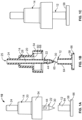
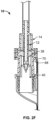
- the connector assembly 10 comprises a first piece 14, a second piece 12, a piercing member 22 centered and enclosed within the first piece 14.
- the connector assembly 10 is used for administering a substance from or into a chamber of a container.
- the connector assembly may be used for any of numerous applications currently known, or that later becomes known, such as, for example, filling a container with a substance, dispensing a substance from or into an opposing device, and any form of fluid transfer.
- the connector assembly is attachable to any of numerous devices, currently known or that later become known, capable of performing the function of a container as described herein.
- the first piece 14 includes a tubular end 24 with a centered (or otherwise) opening 25 therein, a shell 20, and a wide (or otherwise) opening 54 at the end opposite to the tubular end 24.
- the tubular end 24 may be in fluid communication with a conduit or a chamber (not shown) attached thereto.
- the first piece 14 further includes a piercing member 22.
- the piercing member 22 includes a hollow shaft 28 with a tip 30 formed at a dispensing end of the shaft, two or more ports 44 displaced from the tip 30 of the shaft, the ports being in fluid communication with an interior of the hollow shaft 28.
- the piercing member tip 30 is defined by a non-coring, conically-pointed tip; however, as may be recognized by those of ordinary skill in the pertinent art based on the teachings herein, the tip may define any of numerous other tip configurations that are currently known, or that later become known, such as, for example, a trocar tip. Additionally, the tip may be metal or plastic, such as, for example, a tip made of Graphene or Vectra. The piercing member may be metal, plastic, such as Graphene or Vectra, or may be made of a flexible polymer, such as a biocompatible polymer.
- the two ports 44 are diametrically opposed relative to each other; however, as may be recognized by those of ordinary skill in the pertinent art based on the teachings herein, the piercing member may define any number of ports (i.e., one or more ports) that may define any of numerous different configurations and locations.
- the piercing member 22 is integrally molded with the first piece 14; however, as may be recognized by those of ordinary skill in the pertinent art based on the teachings herein, the piercing member may be fixedly attached to the first piece in any of numerous other configurations that currently known, or that later becomes known. Exemplary piercing members are disclosed in co-pending U.S. Patent Application Serial No.
- the second piece 12 includes a friction (or otherwise) fit sleeve 64 with a centered (or otherwise) opening 65 formed therein and attached to and in fluid communication with an alignment cup 66, and a stop surface 58 configured to align with and make contact with a parallel (or otherwise) inner surface 60 within the wide opening 54 of the first piece 14.
- the opening formed within the friction (or otherwise) fit sleeve 64 frictionally (or otherwise) receives a distal end of the piercing member 22 to align and guide the piercing member tip 30 and/or prevent deflection thereof.
- the friction fit sleeve 64 further operates to protect (at least a portion of) the piercing member and to close off the ports 44 of the piercing member prior to usage of the connector assembly.
- the friction fit sleeve 64 may be formed of a relatively flexible material.
- the rim of the inner opening of the wide opening 54 defines an (at least partly) annular (or otherwise) snapping lip 68, further described below with respect to a container (or other device) to which the connector assembly 10 may be attached.
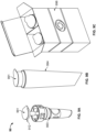
- FIGS. 2A-2B show the connector assembly 10 and a container (or other device) 94 to which the connector assembly 10 may be attached.
- the container 94 includes a chamber 40 having an opening.
- the opening of the chamber 40 of the container comprises a penetrable septum or stopper 38 in fluid communication with and sealing the chamber 40.
- the proximal end of the penetrable septum 38 frictionally fits about the distal end of the opening of the chamber 40.
- the annular snapping lip 68 (which is defined by the first piece 14) defines an inward lip on the piercing member tip 30 side of the first piece 14 that allows a corresponding (at least partly) annular (or otherwise) locking rim 70 ( FIG. 2A ) located at the opening of the chamber 40 of the container 94, to slide therein or otherwise into the first piece 14 with the annular snapping lip 68 snapping over the annular locking rim 70 (as shown in FIG.
- the (at least partly) annular (or otherwise) locking rim 70 defines an outward lip that engages the inward lip after the outward lip slides past the inward lip.)
- the stop surface 58 of the second piece 12 makes contact with the parallel inner surface 60 within the wide opening 54 of the first piece 14 to stop the piercing member 22 from further axial movement in the direction from the distal end of the septum 38 toward the proximal end thereof once the annular snapping lip 68 snaps over the annular locking rim 70 (as shown in FIG. 2F ). Consequently, once the annular snapping lip 68 snaps over the annular locking rim 70, the piercing member is locked within the septum 38.
- the septum 38 comprises a substantially dome-shaped portion over a cylindrical portion and is formed of a resilient and/or elastomeric material.
- the approximately dome-shaped portion and/or the material (resilient and/or elastomeric) allow the septum 38 to move between a first position, as shown in FIG. 2D , where the dome-shaped portion is uncompressed (before the second portion 12 makes contact with the septum 38), and a second position, as shown in FIG 2E , where the dome-shaped portion is compressed (after the second portion 12 makes contact with the septum 38), and later pierced by the piercing member.
- the penetrable septum may be configured in any of numerous configurations currently known, or that later become known, capable of performing the function of the penetrable septum as described herein, such as, for example, a bellows configuration.
- Exemplary penetrable septa are disclosed in the following patents and patent applications which are hereby expressly incorporated by reference as part of the present disclosure: U.S. Patent Application Serial No. 08/424,932, filed April 19, 1995 , entitled "Process for Filling a Sealed Receptacle under Aseptic Conditions," issued as U.S. Patent No. 5,641,004 ; U.S. Patent Application Serial No.
- the configuration of the septum is not limited to the above. Moreover, in some embodiments, the septum may not move between a first position and a second position and may not have both uncompressed and compressed.
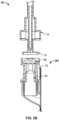
- FIGS. 3A and 3B another connector assembly embodying the present invention is indicated generally by the reference numeral 20.
- the connector assembly 20 is the same as and/or substantially similar to the connector assembly 10 described above, and therefore like reference numerals are preceded by the numeral "3" to indicate like elements.
- the primary difference of the connector assembly 20 in comparison to the connector assembly 10 is that the connector assembly 20 is partially enclosed within a dispensing head 393 and includes a removable seal 391.
- the dispensing head 393 may include a valve 392 and an actuating pump 395. Exemplary such valves and actuating pumps are disclosed in the following patents and patent applications which are: U.S. Application No.
- the valve 392 comprises a one-way valve (which may form an external portion of the dispensing head) and including a valve seat (which may extend axially) and a valve cover (which may be flexible and/or extend axially) seated on the valve seat and defining a normally-closed, seam (which may extend axially) therebetween forming a fluid-tight seal between the valve cover and valve seat, wherein the valve cover is movable relative to the valve seat and the seam is connectable in fluid communication with an outlet aperture to allow the passage of substance through the seam and out of the dispenser.
- a one-way valve which may form an external portion of the dispensing head
- a valve seat which may extend axially
- a valve cover which may be flexible and/or extend axially
- the actuating pump 395 comprises a manually-engageable actuator 397 having a manually-engageable surface 399 on an external side of the manually-engageable actuator 397 and further having an underside that defines or functions as a piston movable between first and second positions relative to a compression chamber (within the dispensing head and/or in fluid communication with the one-way valve) to pressurize substance within such compression chamber.
- variable-volume storage chamber is in fluid communication with the compression chamber for permitting substance to flow from the variable-volume storage chamber into the compression chamber, and (ii) during movement in the direction from the first position toward the second position (a) the compression chamber is not in fluid communication with the variable-volume storage chamber and (b) the substance within the compression chamber is pressurized above the one-way valve opening pressure and dispensed through the normally closed seam and out of the dispenser.
- a removable seal 391 covers and seals an open end of the alignment cup 366 of the second piece 312 of the connector assembly, sealing the opening of the second piece and the piercing member (not shown) therein.
- the first piece is partially enclosed within and forms part of a dispensing head 393.
- the piercing member within the second piece 312 is thereby maintained in a sterile state prior to use.
- the seal 391 Prior to attaching the connector assembly to the opening of a chamber of a container, the seal 391 is removed or peeled away from the proximal end of the alignment cup 366.
- the seal is a foil seal.
- the removable seal may take the form of any of numerous different sealing mechanisms that are currently known, or that later becomes known, such as, for example, a removable liner or a removable cap.
- the seal 391 is a heat-sealed film, e.g., foil or plastic that has barrier properties, particularly for oxygen sensitive materials such as creams contained in the chamber 40 to prevent oxygen permeation into the material contained within the chamber.
- the embodiment of connector assembly 10 shown in FIGS. 1A-1C too may include a removable seal 391 covering the wide opening of the second piece 312, sealing the opening of the alignment cup 366 and the piercing member therein. When the dispensing head is ready for use, the seal is removed from the alignment cup end of the connector assembly.
- the friction fit sleeve 64 of the second piece 12 still seals the ports 44 with respect to ambient atmosphere to thereby maintain the sterility of the ports and of the interior of the piercing member. Since the ports 44 are not exposed to the ambient atmosphere, the ports, interior of the piercing member, and fluid flowing therethrough, are not contaminated and/or are maintained sterile as the fluid is dispensed from or into the chamber 40. Thus, in at least some embodiments, the piercing member is never exposed before, during, and after substance transfer.
- the opening in the alignment cup 66 of the connector assembly is first placed facing the penetrable septum 38, as shown in FIGS. 2A-2B .
- the alignment cup 66 aligns the piercing member 22 with the center of the penetrable septum 38 to facilitate center piercing of the septum by the piercing member.
- the connector assembly 10 is then depressed, as shown in FIGS. 2C-2F , progressively inducing the penetrable septum 38 from the first uncompressed position in FIG. 2D toward the compressed and pierced position in FIG> 2F.
- the friction fit sleeve starts sliding up the piercing member further exposing the tip 30 to facilitate piercing of the septum, and the resistance of the surface of the septum to puncture induces the annular snapping lip 68 of the first piece 14 to fully engage the end of the annular locking rim 70 of the container, wherein the annular snapping lip 68 of the first piece 14 moves from abutting the end of the annular locking rim 70 to snapping into the flange portion of the annular locking rim 70, as shown in FIG. 2F .
- the piercing member tip 30 fully penetrates the septum 38 and the ports 44 start to emerge out of the friction fit sleeve 64, as shown in FIG. 2E .
- the contact (friction or otherwise) between the septum and the piercing member wipes (in effect) the piercing member to remove (or at least significantly reduce) any germs and other contaminants that may be present on the external surface of the piercing member, while the ports 44 remain unexposed until they pass through the septum.
- the connector assembly is further depressed, frictional engagement between the opening of the alignment cup 66 and the septum 38, prevents further movement of the connector assembly relative to the septum.
- the connector assembly cannot be reused once the annular locking rim 70 has fully snapped into position.
- the locking between the annular snapping lip 68 of the connector assembly and the annular locking rim 70 of the container prevents the piercing member 22 from moving back. Therefore, once the connector assembly 10 snaps into and locks into position as shown in FIG. 2F , it cannot be unlocked.
- the connector assembly permits multiple intact transfers of substances out of a filled chamber 40 until the chamber is empty. After the chamber 40 is emptied, the container along with the connector assembly 10 is discarded. In other words, the connector assembly is configured for single use, is not re-used, and can only be disposed of along with the container to which it is attached. This prevents cross-contamination common in reusable prior art connectors.
- the connector assembly may be used in various applications including cream/liquid dispensing, eyedroppers, dermatologic dispensers, and other substance transfers without the need to add preservatives therein to maintain sterility.
- the connector assembly may also be used to fill non-preserved liquids into intact closed containers.
- the connector assembly may further be used as an interface between an intact dispensing system and an intact container. In all applications, both the connector assembly and the opening of the chamber are sealed by film to protect them from contamination during shelf life. This permits the use of the above described connector assembly in harsh environments, such as hospitals and in non-sterile open environments.
- FIGS. 4A-14E illustrate additional embodiments each of which includes one or more connector assembly.
- These connector assemblies are the same as and/or substantially similar to the connector assemblies 10 and/or 20 described above, and therefore like reference numerals preceded by the numerals "4" through "14" (i.e., irrespective of letter suffixes that may be included) are used to indicate like elements.
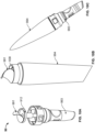
- FIGS. 4A, 4B are perspective cross-sectional views of two fluid and/or other substance transfer systems (and/or assemblies) 400A, 400B, respectively.
- the two transfer systems 400A, 400B each include a conduit 496A, 496B, respectively, having two ends.
- Each transfer system further includes two connector assemblies.
- Transfer system 400A includes connector assemblies 410A, 410A, which may be, but are not required to be, identical to one another.
- Each of the connector assemblies 410A, 410A is attached to a respective one of the ends of conduit 496A.
- transfer system 400B includes connector assemblies 410B, 410B, which may be, but are not required to be, identical to one another, and each of the connector assemblies 410B, 410B is attached to a respective one of the ends of conduit 496B.
- Three of the connector assemblies are shown in a similar state.
- One of the connector assemblies i.e., the connector assembly shown attached to the lower end of the conduit in FIG. 4B , the piercing member 422B is enclosed within the second piece 412B. This protects the tip and ports of the piercing member from contamination.
- the conduit allows for fluid and/or other substance transfer between two chambers (not shown) that may be spaced apart from each other.
- one or both of the chambers may be the same as and/or similar to chamber 40 and/or any other type of chamber.
- Each chamber may have a penetrable septum, with the piercing member of each connecting assembly piercing the septum and forming a fluid-tight hermetic seal with a respective chamber.
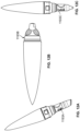
- FIGS. 5A, 5C are perspective views of two fluid and/or other substance transfer systems (and/or assemblies), and FIGS. 5B, 5D are corresponding perspective cross-sectional views of the two transfer systems.
- Each transfer system includes a connector assembly attached to a conduit.
- the connector assembly 510A is attached to one end of the conduit while a self-sealing valve connector 598A is attached to its other end.
- the connector assembly 510B is attached to one end of the conduit while a self-closing valve 598B is attached to its other end.
- FIG. 6A is a perspective view of a fluid and/or other substance transfer system (and/or assembly) and FIG. 6B is a corresponding perspective cross-sectional view of the transfer system, which includes a connector assembly 610A attached to a conduit
- FIGS. 6C, 6D are perspective partial cross-sectional views of further fluid and/or other substance transfer systems (and/or assemblies), which include the connector assembly 610B attached to a conduit.
- the connector assembly 610A is attached to one end of the conduit with another type of self-sealing valve connector 698A being attached to its other end.
- FIG. 6A is a perspective view of a fluid and/or other substance transfer system (and/or assembly)
- FIG. 6B is a corresponding perspective cross-sectional view of the transfer system, which includes a connector assembly 610A attached to a conduit
- FIGS. 6C, 6D are perspective partial cross-sectional views of further fluid and/or other substance transfer systems (and/or assemblies), which include the connector assembly 610B attached
- FIG. 6C shows the connector assembly 610B attached to one end of the conduit and a male connector 698B attached to the other end of the conduit
- FIG. 6D shows the connector assembly 610B attached to one end of the conduit and a female connector 698C attached to the other end of the conduit.
- Exemplary such connectors are disclosed in the following co-pending patent applications, U.S. Patent Application No. 14/536,566, filed November 7, 2014 , entitled “Device for Connecting or Filling and Method", which claims the benefit of similarly to similarly-titled U.S. Provisional Patent Application Nos. 61/641,248, filed May 1, 2012 , and 61/794,255, filed March 15, 2013 .
- FIG. 7A is a perspective view of a fluid and/or other substance transfer system (and/or assembly), which includes a conduit, the connector assembly 710 attached to an end of the conduit and another device attached to the other end of the conduit, shown along with a pouch (or other type of container) 794 (which may include one or more chambers 740 that one or more of which) the connector assembly conduit attaches to, while FIG. 7B is a perspective cross-sectional view of the transfer system that includes the connector assembly 710 and conduit shown in FIG. 7A .
- Exemplary such pouches are disclosed in the following co-pending patent application, U.S. Provisional Patent Application entitled "Pouch with Heat-Sealed External Fitment,” filed on even date herewith, and associated with Attorney Docket No. 100811.00053.
- the connector assembly forms a fluid-tight hermetic seal with a port 740 of the pouch to permit fluid flow therethrough.
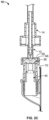
- FIG. 8A shows perspective views of an assembly, in assembled and partly disassembled states, that includes the connector assembly 20 ( FIGS. 3A-3B ) partially enclosed within a dispensing head 893 that attaches to a squeezable tube (or other type of container) 894 (which may include fluid and/or other substance(s) to be dispensed) to form a fluid-tight hermetic seal, while FIG. 8B is a perspective cross-sectional view of the embodiment of FIG. 8A .
- the dispensing head 893 is substantially similar to the dispensing head 393 explained above with respect to FIGS. 3A and 3B .
- the easy attachment of the dispensing head 893 to the tube 894 without exposing the piercing member to the outside allows for safe assembly by patients in hospitals and/or other harsh (or potentially harsh) environments.
- FIG. 9A is a perspective view of an embodiment of a connector assembly 90 having a sealed dispensing head 993 that attaches to a squeezable tube 994 (which may include fluid and/or other substance(s) to be dispensed), while FIG. 9B is a perspective view of a sealed tube 994, and FIG. 9C is a perspective view showing a shipping kit 998 containing the sealed dispensing head 993 and the sealed tube 994.
- the dispensing head 993 is substantially similar to the dispensing head 393 shown in FIG. 3A .
- the tube 994 too is shown sealed by a removable seal 991, the removable seal being substantially similar to the removable seal 391 described above with respect to FIG. 3A .
- Both the sealed dispenser head and the sealed tube may be packed together in a kit as shown in FIG. 9C to facilitate easy shipment.
- the removable seal may act as a complete barrier preventing contact with contaminants and the ambient atmosphere thereby improving shelf life.
- FIG. 10A is a perspective view of connector assembly 90 with the dispensing head 993 shown in FIG. 9A with its seal 991 in the process of being peeled off
- FIG. 10B is a perspective view of the tube 994 of FIG. 9B with its seal 991 being peeled off
- FIG. 10C is a perspective view showing the dispensing head 993 of FIG. 10A attached to the tube 994 of FIG. 10B .
- the user may peel of the removable seal 991 on the dispensing head and on the squeezable tube and connect the dispensing head to the tube to from a fluid-tight hermetic connection between the dispensing head and an opening of the tube by following the steps similar to those explained with regard to FIGS. 2A-2F .
- FIG. 11 shows perspective views of other embodiments of dispensing heads that may be attached to a squeezable tube and/or other type(s) of container(s) (or other type(s) of device(s)).
- the dispensing head 1193A is configured as a surface applicator and may connect to the tube shown in FIG. 12A ;
- the dispensing head 1193B is configured for a larger application tube and may connect to the tube shown in FIG. 12B ;
- the dispensing head 1193D is configured for spot treatment and may connect to the tube shown in FIG. 12C .
- FIG. 13 is a perspective view of a fluid and/or other substance transfer system (and/or assembly), which includes a conduit, the connector assembly 1310 attached to one end of the conduit with an alternate connector 1398 attached to the other end of the conduit.
- Exemplary such alternate connectors are disclosed in the following co-pending patent applications U.S. Patent Application No. 13/874,839, filed May 1, 2013 , entitled “Device for Connecting or Filling and Method", which claims the benefit of similarly titled U.S. Provisional Patent Application No. 61/641,248, filed May 1, 2012 , and similarly titled U.S. Provisional Patent Application No. 61/794,255, filed March 15, 2013 ; and U.S. Patent Application No.
- FIGS. 14A, 14C, 14D and 14E show additional perspective views of an embodiment of the dispensing head 1493 and an embodiment of the squeezable tube that it may be used to connect to, while 14B is a perspective cross-section view of one embodiment of the squeezable tube.
- FIG. 14B shows a groove 1496 wherein the septum 1438 is received in at least some embodiments.
- one or more portions of one or more embodiments disclosed herein may be embodied in a method, an apparatus, a connector, a coupler, a conduit, a transport, device, a dispenser, an assembly, a kit, a system and/or any combination thereof.
- the features disclosed herein can be used in any combination or configuration, and is not limited to the particular combinations or configurations expressly specified or illustrated herein.
- one or more of the features disclosed herein may be used without one or more other feature disclosed herein.
- each of the features disclosed herein may be used without any one or more of the other features disclosed herein.
- one or more of the features disclosed herein may be used in combination with one or more other features that is/are disclosed (herein) independently of said one or more of the features.
- each of the features disclosed (herein) may be used in combination with any one or more other feature that is disclosed herein.
- a locking mechanism is not limited to two lips that engage one another.
- a locking mechanism may comprise any type of catch and/or other structures (cooperating or otherwise) that define an interference to prevent release and/or other relative movement.
- the phrase "A and/or B” means the following combinations: (i) A but not B, (ii) B but not A, and (iii) A and B. It should be recognized that the meaning of any phrase that includes the term “and/or” can be determined based on the above.
- the phrase "A, B and/or C” means the following combinations: (i) A but not B and not C, (ii) B but not A and not C, (iii) C but not A and not B, (iv) A and B but not C, (v) A and C but not B, (vi) B and C but not A, and (vii) A and B and C. Further combinations using and/or shall be similarly construed.
- the components of the connector assembly may be made of any of numerous different materials that are currently known, or that later become known for performing the function(s) of each such component.
- the components of the connector assembly may take any of numerous different shapes and/or configurations.
- the connector assembly may be used to inject any of numerous different types of fluids or other substances for any of numerous different applications, including, for example, medicaments, pharmaceuticals, vaccines, liquid nutrition products, supplements, and numerous other products that are currently known, or later become known.
- the characteristics of the connector assembly may be adjusted, including for example the shape and/or configuration of the penetrable septum and/or the piercing member, to meet the requirements of any of numerous different applications and/or products to be dispensed. Accordingly, this detailed description of currently preferred embodiments is to be taken in an illustrative, as opposed to a limiting sense.
Landscapes
- Health & Medical Sciences (AREA)
- Life Sciences & Earth Sciences (AREA)
- Veterinary Medicine (AREA)
- Public Health (AREA)
- General Health & Medical Sciences (AREA)
- Animal Behavior & Ethology (AREA)
- Heart & Thoracic Surgery (AREA)
- Anesthesiology (AREA)
- Hematology (AREA)
- Biomedical Technology (AREA)
- Engineering & Computer Science (AREA)
- Pharmacology & Pharmacy (AREA)
- Pulmonology (AREA)
- Physics & Mathematics (AREA)
- Fluid Mechanics (AREA)
- Vascular Medicine (AREA)
- Epidemiology (AREA)
- Medical Preparation Storing Or Oral Administration Devices (AREA)
- Infusion, Injection, And Reservoir Apparatuses (AREA)
Claims (14)
- Verbinder (10, 20, 90, 410A, 410B, 510A, 510B, 610A, 610B, 710, 1310), umfassend:ein erstes Teil (14, 414A, 414B, 514A, 514B, 614A, 614B, 714B, 1314);ein Durchstechelement (22, 422A, 422B, 522A, 522B, 622B, 722B, 822), das an dem ersten Teil (14, 414A, 414B, 514A, 514B, 614A, 614B, 714B, 1314) befestigt ist; undein zweites Teil (12, 312, 412A, 412B, 512A, 512B, 612A, 612B, 712B, 812, 912, 1312, 1412), wobei das Durchstechelement (22, 422A, 422B, 522A, 522B, 622B, 722B, 822) gleitfähig innerhalb des zweiten Teils (12, 312, 412A, 412B, 512A, 512B, 612A, 612B, 712B, 812, 912, 1312, 1412) aufnehmbar ist;wobei das Durchstechelement (22, 422A, 422B, 522A, 522B, 622B, 722B, 822) und das zweite Teil (12, 312, 412A, 412B, 512A, 512B, 612A, 612B, 712B, 812, 912, 1312, 1412) relativ zueinander zwischen einer ersten Position, in der das zweite Teil (12, 312, 412A, 412B, 512A, 512B, 612A, 612B, 712B, 812, 912, 1312, 1412) eine Durchflussöffnung (40) schließt, und einer zweiten Position, in der die Durchflussöffnung (40) offen ist, beweglich sind:
dadurch gekennzeichnet, dass
das erste Teil (14, 414A, 414B, 514A, 514B, 614A, 614B, 714B, 1314) ferner einen Verriegelungsmechanismus aufweist, der eingerichtet ist, das erste Teil (14, 414A, 414B, 514A, 514B, 614A, 614B, 714B, 1314) verriegelnd mit einer Vorrichtung (94, 794, 894) zu verbinden, wenn es mit dieser in Eingriff ist, wodurch das erste Teil (14, 414A, 414B, 514A, 514B, 614A, 614B, 714B, 1314) permanent mit der Vorrichtung (94, 794, 894) verriegelt ist und eine nachfolgende Trennung des ersten Teils (14, 414A, 414B, 514A, 514B, 614A, 614B, 714B, 1314) und der Vorrichtung (94, 794, 894) verhindert wird. - Verbinder (10, 20, 90, 410A, 410B, 510A, 510B, 610A, 610B, 710, 1310) nach Anspruch 1, wobei, wenn das erste Teil (14, 414A, 414B, 514A, 514B, 614A, 614B, 714B, 1314) und die Vorrichtung (94, 794, 894) in Eingriff gekommen sind, das zweite Teil (12, 312, 412A, 412B, 512A, 512B, 612A, 612B, 712B, 812, 912, 1312, 1412) aus der ersten Position in die zweite Position bewegt wird.
- Verbinder (10, 20, 90, 410A, 410B, 510A, 510B, 610A, 610B, 710, 1310) nach einem der Ansprüche 1 oder 2, wobei der Verriegelungsmechanismus eine einwärts gerichtete Lippe (68) auf dem ersten Teil (14, 414A, 414B, 514A, 514B, 614A, 614B, 714B, 1314) umfasst, wobei die einwärts gerichtete Lippe (68) vorzugsweise eingerichtet ist, in Eingriff mit einer auswärts gerichteten Lippe (70) auf der Vorrichtung (94, 794, 894) zu kommen, nachdem die auswärts gerichtete Lippe (70) an der einwärts gerichteten Lippe (68) vorbei geglitten ist.
- Verbinder (10, 20, 90, 410A, 410B, 510A, 510B, 610A, 610B, 710, 1310) nach Anspruch 3, wobei das erste Teil (14, 414A, 414B, 514A, 514B, 614A, 614B, 714B, 1314) eine Innenoberfläche (60) umfasst und das zweite Teil (12, 312, 412A, 412B, 512A, 512B, 612A, 612B, 712B, 812, 912, 1312, 1412) eine Stoppoberfläche (58) umfasst, die Kontakt mit der Innenoberfläche (60) herstellt, um das Durchstechelement (22, 422A, 422B, 522A, 522B, 622B, 722B, 822) zu stoppen, so dass es keine weitere axiale Bewegung relativ zu der Vorrichtung (94, 794, 894) mehr durchführt, wenn die einwärts gerichtete Lippe (68) in Eingriff mit der auswärts gerichteten Lippe (70) gekommen ist.
- Verbinder (10, 20, 90, 410A, 410B, 510A, 510B, 610A, 610B, 710, 1310) nach einem der Ansprüche 1 bis 4, wobei der Verbinder (10, 20, 90, 410A, 410B, 510A, 510B, 610A, 610B, 710, 1310) teilweise innerhalb eines Ausgabekopfes (393, 893, 993, 1193A, 1193B, 1193C, 1193D, 1493) eingeschlossen ist, wobei der Ausgabekopf (393, 893, 993, 1193A, 1193B, 1193C, 1193D, 1493) vorzugsweise ein Einwegventil (392) und einen manuell in Eingriff bringbaren Aktuator (397) aufweist.
- Verbinder (10, 20, 90, 410A, 410B, 510A, 510B, 610A, 610B, 710, 1310) nach einem der Ansprüche 1 bis 5, wobei der Verbinder (10, 20, 90, 410A, 410B, 510A, 510B, 610A, 610B, 710, 1310) an einer Quetschtube (894, 994) befestigbar ist.
- Verbinder (10, 20, 90, 410A, 410B, 510A, 510B, 610A, 610B, 710, 1310) nach einem der Ansprüche 1 bis 6, ferner umfassend eine entfernbare Dichtung (391, 991) auf dem zweiten Teil (12, 312, 412A, 412B, 512A, 512B, 612A, 612B, 712B, 812, 912, 1312, 1412).
- Verbinder (10, 20, 90, 410A, 410B, 510A, 510B, 610A, 610B, 710, 1310) nach einem der Ansprüche 1 bis 7, wobei der Verriegelungsmechanismus nicht entriegelt werden kann.
- Vorrichtung, umfassend:den Verbinder (10, 20, 90, 410A, 410B, 510A, 510B, 610A, 610B, 710, 1310) nach einem der Ansprüche 1 bis 8; undein penetrierbares Septum (38, 838, 938, 1438), das zwischen (i) einer ersten Position, in der das penetrierbare Septum (38, 838, 938, 1438) unkomprimiert ist, und (ii) einer zweiten Position, in der das penetrierbare Septum (38, 838, 938, 1438) komprimiert ist, beweglich ist;wobei das Durchstechelement (22, 422A, 422B, 522A, 522B, 622B, 722B, 822) und/oder das penetrierbare Septum (38, 838, 938, 1438) in Bezug auf das andere von dem Durchstechelement (22, 422A, 422B, 522A, 522B, 622B, 722B, 822) und dem penetrierbaren Septum (38, 838, 938, 1438) in einer entriegelten Position vor und während des Gebrauchs des Verbinders (10, 20, 90, 410A, 410B, 510A, 510B, 610A, 610B, 710, 1310) axial beweglich sind/ist, und das mindestens eine von dem Durchstechelement (22, 422A, 422B, 522A, 522B, 622B, 722B, 822) und dem penetrierbaren Septum (38, 838, 938, 1438) in einer verriegelten Position nicht länger in Bezug zu dem anderen von dem Durchstechelement (22, 422A, 422B, 522A, 522B, 622B, 722B, 822) und dem penetrierbaren Septum (38, 838, 938, 1438) axial beweglich ist.
- Vorrichtung nach Anspruch 9, wobei das zweite Teil (12, 312, 412A, 412B, 512A, 512B, 612A, 612B, 712B, 812, 912, 1312, 1412) eingerichtet ist, das Septum (38, 838, 938, 1438) von der ersten Position in die zweite Position zu bewegen.
- Vorrichtung nach Anspruch 10, wobei das zweite Teil (12, 312, 412A, 412B, 512A, 512B, 612A, 612B, 712B, 812, 912, 1312, 1412) ferner eingerichtet ist, sich aus einer Anfangsposition relativ zu dem ersten Teil (14, 414A, 414B, 514A, 514B, 614A, 614B, 714B, 1314), in der das zweite Teil (12, 312, 412A, 412B, 512A, 512B, 612A, 612B, 712B, 812, 912, 1312, 1412) nicht in Eingriff mit dem Septum (38, 838, 938, 1438) ist und das Septum (38, 838, 938, 1438) sich in der ersten Position befindet, zu einer vorgeschobenen anderen Position relativ zu dem ersten Teil (14, 414A, 414B, 514A, 514B, 614A, 614B, 714B, 1314) zu bewegen, in der das zweite Teil (12, 312, 412A, 412B, 512A, 512B, 612A, 612B, 712B, 812, 912, 1312, 1412) in Eingriff mit dem Septum (38, 838, 938, 1438) ist und das Septum (38, 838, 938, 1438) sich in der zweiten Position befindet.
- Verfahren, umfassend:
Einführen eines Durchstechelements (22, 422A, 422B, 522A, 522B, 622B, 722B, 822) eines Verbinders nach Anspruch 1 (10, 20, 90, 410A, 410B, 510A, 510B, 610A, 610B, 710, 1310) in ein penetrierbares Septum (38, 838, 938, 1438) einer Vorrichtung (94, 794, 894, 994), wobei das Verfahren ferner ein permanentes Verriegeln des ersten Teils (14, 414A, 414B, 514A, 514B, 614A, 614B, 714B, 1314) mit der Vorrichtung (94, 794, 894) mittels des Verriegelungsmechanismus offenbart, wodurch das Durchstechelement (22, 422A, 422B, 522A, 522B, 622B, 722B, 822) des Verbinders (10, 20, 90, 410A, 410B, 510A, 510B, 610A, 610B, 710, 1310) in dem penetrierbaren Septum (38, 838, 938, 1438) verriegelt wird. - Verfahren nach Anspruch 12, wobei das Verriegeln ein Fixieren relativer Positionierung des Durchstechelements (22, 422A, 422B, 522A, 522B, 622B, 722B, 822) und des penetrierbaren Septums (38, 838, 938, 1438) umfasst, so dass keiner von ihnen in Bezug zu dem anderen axial beweglich ist.
- Verfahren nach einem der Ansprüche 12 oder 13, wobei das penetrierbare Septum (38, 838, 938, 1438) ein Teil einer Vorrichtung (94, 794, 894) ist, und das Verfahren ferner ein Starten eines Bewegungsschritts vor dem Einführschritt umfasst, wobei der Bewegungsschritt ein Bewegen von einem oder mehreren von dem Verbinder (10, 20, 90, 410A, 410B, 510A, 510B, 610A, 610B, 710, 1310) oder der Vorrichtung (94, 794, 894) aufeinander zu umfasst.
Priority Applications (1)
| Application Number | Priority Date | Filing Date | Title |
|---|---|---|---|
| EP25181134.5A EP4588500A2 (de) | 2016-01-19 | 2017-01-19 | Einwegverbinder |
Applications Claiming Priority (2)
| Application Number | Priority Date | Filing Date | Title |
|---|---|---|---|
| US201662280693P | 2016-01-19 | 2016-01-19 | |
| PCT/US2017/014204 WO2017127589A1 (en) | 2016-01-19 | 2017-01-19 | Single use connectors |
Related Child Applications (1)
| Application Number | Title | Priority Date | Filing Date |
|---|---|---|---|
| EP25181134.5A Division EP4588500A2 (de) | 2016-01-19 | 2017-01-19 | Einwegverbinder |
Publications (3)
| Publication Number | Publication Date |
|---|---|
| EP3405231A1 EP3405231A1 (de) | 2018-11-28 |
| EP3405231A4 EP3405231A4 (de) | 2019-10-16 |
| EP3405231B1 true EP3405231B1 (de) | 2025-06-25 |
Family
ID=59313544
Family Applications (2)
| Application Number | Title | Priority Date | Filing Date |
|---|---|---|---|
| EP25181134.5A Pending EP4588500A2 (de) | 2016-01-19 | 2017-01-19 | Einwegverbinder |
| EP17741958.7A Active EP3405231B1 (de) | 2016-01-19 | 2017-01-19 | Verbinder zum einmaligen gebrauch |
Family Applications Before (1)
| Application Number | Title | Priority Date | Filing Date |
|---|---|---|---|
| EP25181134.5A Pending EP4588500A2 (de) | 2016-01-19 | 2017-01-19 | Einwegverbinder |
Country Status (5)
| Country | Link |
|---|---|
| US (1) | US10426701B2 (de) |
| EP (2) | EP4588500A2 (de) |
| JP (1) | JP2019502483A (de) |
| CA (1) | CA3050846A1 (de) |
| WO (1) | WO2017127589A1 (de) |
Families Citing this family (7)
| Publication number | Priority date | Publication date | Assignee | Title |
|---|---|---|---|---|
| US11007359B2 (en) * | 2017-02-16 | 2021-05-18 | Canadian Hospital Specialties Limited | Connector for catheter |
| DE102019116970B4 (de) * | 2019-06-24 | 2023-11-30 | Sartorius Stedim Biotech Gmbh | Sterilverbinder für den sterilen Transfer eines flüssigen Mediums |
| KR102635908B1 (ko) * | 2020-11-25 | 2024-02-13 | (주)이셀 | 일회용 샘플링 시스템 |
| WO2022265958A1 (en) * | 2021-06-17 | 2022-12-22 | Colder Products Company | Aseptic fluid couplings |
| WO2023229704A1 (en) * | 2022-05-23 | 2023-11-30 | Colder Products Company | Aseptic fluid couplings |
| US20240238576A1 (en) * | 2023-01-18 | 2024-07-18 | Carefusion 303, Inc | Split septum needle free connector and post needle free connector with sleeve septum fuse concept |
| DE102023135598A1 (de) * | 2023-12-18 | 2025-06-18 | B. Braun Melsungen Aktiengesellschaft | Medizinisches Infusionsset und Verfahren zu dessen Herrichtung für den Gebrauch |
Family Cites Families (146)
| Publication number | Priority date | Publication date | Assignee | Title |
|---|---|---|---|---|
| US2304390A (en) | 1940-11-14 | 1942-12-08 | Arthur L Parker | Coupling |
| US2819914A (en) | 1955-03-17 | 1958-01-14 | George R Eitner | Fluid line coupling device |
| US3367366A (en) | 1965-10-11 | 1968-02-06 | Universal Oil Prod Co | Disconnect with minimum inclusion |
| FR1479110A (fr) | 1966-05-10 | 1967-04-28 | Bouchon perforateur à membrane souple ou déformable | |
| IT957974B (it) | 1971-05-27 | 1973-10-20 | Visscher P De | Perfezionamento nei raccordi o giunti per il collegamento di ambienti |
| US3916929A (en) | 1974-08-16 | 1975-11-04 | Scovill Manufacturing Co | Self-sealing break-away fitting |
| US4076147A (en) | 1976-05-04 | 1978-02-28 | Schmit Justin M | Liquid container having a plastic film pouch and a piercing element to open the plastic film pouch |
| US4112944A (en) | 1976-12-13 | 1978-09-12 | Williams Gayland M | Tube clamp and piercing device |
| US4232851A (en) | 1979-02-06 | 1980-11-11 | Textron Inc. | Fluid control valve and liner therefor |
| US4440316A (en) | 1980-02-27 | 1984-04-03 | Trinity Associates | Combined piercer and valve for flexible bag |
| ATE9675T1 (de) | 1980-07-03 | 1984-10-15 | Wrightcel Ltd. | Hahn. |
| US4384660A (en) | 1981-07-27 | 1983-05-24 | Realex Corporation | Tamper-proof clip for uplocking plungers of pump dispensers |
| US4445551A (en) | 1981-11-09 | 1984-05-01 | Bond Curtis J | Quick-disconnect coupling and valve assembly |
| US4473369A (en) | 1982-01-11 | 1984-09-25 | Baxter Travenol Laboratories, Inc. | Continuous ambulatory peritoneal dialysis clamping system |
| US4752292A (en) | 1983-01-24 | 1988-06-21 | Icu Medical, Inc. | Medical connector |
| US5199947A (en) | 1983-01-24 | 1993-04-06 | Icu Medical, Inc. | Method of locking an influent line to a piggyback connector |
| US5344414A (en) | 1983-01-24 | 1994-09-06 | Icu Medical Inc. | Medical connector |
| US5281206A (en) | 1983-01-24 | 1994-01-25 | Icu Medical, Inc. | Needle connector with rotatable collar |
| NL8300386A (nl) | 1983-02-02 | 1984-09-03 | Steritech Bv | Inrichting voor het steriel met elkaar in verbinding stellen van twee kamers. |
| US4706827A (en) | 1984-04-12 | 1987-11-17 | Baxter Travenol Laboratories, Inc. | Container such as a nursing container, and packaging arrangement therefor |
| SE451089B (sv) | 1985-12-20 | 1987-08-31 | Steridose Systems Ab | Kontaminationsfri koppling |
| US4700744A (en) | 1986-03-10 | 1987-10-20 | Rutter Christopher C | Double shut-off fluid dispenser element |
| US4931048A (en) | 1986-04-07 | 1990-06-05 | Icu Medical, Inc. | Medical device |
| US4778453A (en) | 1986-04-07 | 1988-10-18 | Icu Medical, Inc. | Medical device |
| US4790832A (en) | 1986-06-06 | 1988-12-13 | Icu Medical, Inc. | System for administering medication nasally to a patient |
| EP0258579A1 (de) | 1986-08-01 | 1988-03-09 | Societe Des Produits Nestle S.A. | Vorrichtung zum Anschliessen und Entleeren von Verpackungen |
| US4709725A (en) | 1987-02-17 | 1987-12-01 | Vetco Gray, Inc. | Metal-to-metal seal structure |
| US4816024A (en) | 1987-04-13 | 1989-03-28 | Icu Medical, Inc. | Medical device |
| US4846805A (en) | 1987-12-04 | 1989-07-11 | Icu Medical, Inc. | Catheter insert device |
| NL8703114A (nl) | 1987-12-23 | 1989-07-17 | Filoform Chem Ind Bv | Werkwijze voor het aanbrengen van een aansluitnippel op een buidel, en een inrichting voor het uitvoeren van deze werkwijze. |
| US4842591A (en) | 1988-01-21 | 1989-06-27 | Luther Ronald B | Connector with one-way septum valve, and assembly |
| US4917149A (en) | 1988-04-14 | 1990-04-17 | Dayco Products, Inc. | Breakaway coupling, conduit system utilizing the coupling and methods of making the same |
| EP0588375B1 (de) | 1988-06-02 | 1999-05-06 | Piero Marrucchi | Vorrichtung zum Behandeln und Übertragen von Stoffen zwischen abgeschlossenen Räumen |
| US4941517A (en) | 1988-10-20 | 1990-07-17 | Galloway Trust | Aseptic fluid transfer apparatus and methods |
| DE3926024C2 (de) | 1989-08-07 | 1994-10-27 | Minnesota Mining & Mfg | Vorrichtung zum Entnehmen von fließfähigem Füllgut durch eine flexible Wand eines Beutels |
| US5694686A (en) | 1991-12-18 | 1997-12-09 | Icu Medical, Inc. | Method for assembling a medical valve |
| CZ149294A3 (en) | 1991-12-18 | 1994-11-16 | Icu Medical Inc | Medicinal valve |
| US5211197A (en) | 1992-01-03 | 1993-05-18 | Aeroquip Corporation | Quick disconnect liquid line coupling with volumertric expansion couping element |
| US5478328A (en) | 1992-05-22 | 1995-12-26 | Silverman; David G. | Methods of minimizing disease transmission by used hypodermic needles, and hypodermic needles adapted for carrying out the method |
| DE69303434T2 (de) | 1992-07-02 | 1997-02-06 | Cusi Lab | Behälter für pharmazeutische Produkte aus zwei gesonderten Komponenten, mit Mitteln zu deren Mischung und dosierter Ausgabe |
| FR2699522B1 (fr) | 1992-12-17 | 1995-01-20 | Gestra | Dispositif de bouchage pour récipient à parois souples. |
| FR2719018B1 (fr) | 1994-04-26 | 1996-07-12 | Py Daniel C | Procédé pour remplir dans des conditions aseptiques un récipient obturé. |
| JPH10504736A (ja) | 1994-06-24 | 1998-05-12 | アイシーユー メディカル、インコーポレイティッド | 流体移送デバイス及び使用方法 |
| US5482083A (en) | 1994-10-24 | 1996-01-09 | Aeroquip Corporation | Quick connect coupling |
| US5501676A (en) * | 1995-01-13 | 1996-03-26 | Sanofi Winthrop, Inc. | Coupling system for safety cannula |
| US5492147A (en) | 1995-01-17 | 1996-02-20 | Aeroquip Corporation | Dry break coupling |
| US5810768A (en) | 1995-06-07 | 1998-09-22 | Icu Medical, Inc. | Medical connector |
| US5810792A (en) | 1996-04-03 | 1998-09-22 | Icu Medical, Inc. | Locking blunt cannula |
| US5791376A (en) | 1996-05-16 | 1998-08-11 | Mega Systems & Chemicals, Inc. | Quick disconnect valve system for abrasive slurries |
| ATE262951T1 (de) | 1996-11-18 | 2004-04-15 | Nypro Inc | Abwischbares luer-ventil |
| US6245048B1 (en) | 1996-12-16 | 2001-06-12 | Icu Medical, Inc. | Medical valve with positive flow characteristics |
| JP2001506156A (ja) | 1996-12-16 | 2001-05-15 | アイシーユー メディカル、インコーポレイテッド | ポジティブ・フロー・バルブ |
| US6024242A (en) | 1996-12-24 | 2000-02-15 | Eidson Steel Products, Inc. | Removably insertable internal containment reservoir |
| US5878798A (en) | 1997-02-28 | 1999-03-09 | Eastman Kodak Company | Valve system |
| EP1716885A3 (de) | 1997-05-09 | 2006-11-15 | Pall Corporation | Verbindungsanordnungen, Fluidsysteme und Methoden zum Erstellen einer Verbindung |
| SE514699C2 (sv) | 1997-09-29 | 2001-04-02 | Asept Int Ab | Portioneringsanordning och förpackning ur vilken en flytande produkt, företrädesvis flytande livsmedel, skall portioneras ut med hjälp av portioneringsanordningen samt kopplingsanordning vid nämnda förpackning |
| SE515112C2 (sv) | 1997-09-29 | 2001-06-11 | Asept Int Ab | Förpackning, sätt att framställa denna och koppling för densamma |
| DE19751489A1 (de) | 1997-11-20 | 1999-05-27 | Nutrichem Diaet & Pharma Gmbh | Doppelbeutel zur Applikation einer fluiden Substanz |
| ZA9811087B (en) | 1997-12-04 | 1999-06-03 | Bracco Research Sa | Automatic liquid injection system and method |
| US6041805A (en) | 1998-07-07 | 2000-03-28 | Imation Corp. | Valve assembly for a removable ink cartridge |
| US6113583A (en) * | 1998-09-15 | 2000-09-05 | Baxter International Inc. | Vial connecting device for a sliding reconstitution device for a diluent container |
| AR021220A1 (es) * | 1998-09-15 | 2002-07-03 | Baxter Int | DISPOSITIVO DE CONEXIoN PARA ESTABLECER UNA COMUNICACIoN FLUíDA ENTRE UN PRIMER RECIPIENTE Y UN SEGUNDO RECIPIENTE. |
| US7425209B2 (en) * | 1998-09-15 | 2008-09-16 | Baxter International Inc. | Sliding reconstitution device for a diluent container |
| US6726672B1 (en) | 1998-09-28 | 2004-04-27 | Icu Medical, Inc. | Intravenous drug access system |
| DE19847594C1 (de) | 1998-10-15 | 2000-06-08 | Nutrichem Diaet & Pharma Gmbh | Beutel zur Aufnahme einer insbesondere in den menschlichen oder tierischen Körper einzubringenden ersten Substanz |
| US6032691A (en) | 1999-03-29 | 2000-03-07 | Kaylynn, Inc. | Valve assembly |
| DE19940706A1 (de) | 1999-08-27 | 2001-03-08 | Schott Glas | Verschließbarer Glasbehälter mit einem umspritzten Kunststoffüberzug und Verfahren zu seiner Herstellung |
| US6453956B2 (en) | 1999-11-05 | 2002-09-24 | Medtronic Minimed, Inc. | Needle safe transfer guard |
| CA2393934A1 (en) | 1999-12-14 | 2001-06-21 | Icu Medical, Inc. | Method of manufacturing a multiple component device |
| US6604561B2 (en) | 2000-02-11 | 2003-08-12 | Medical Instill Technologies, Inc. | Medicament vial having a heat-sealable cap, and apparatus and method for filling the vial |
| DE10009566A1 (de) * | 2000-02-29 | 2001-09-06 | Agfa Gevaert Ag | Farbfotografisches Silberhalogenidmaterial |
| EP1305225A4 (de) | 2000-06-21 | 2003-08-27 | Paul Francois Roos | Selbstschliessende kupplung |
| US6695817B1 (en) | 2000-07-11 | 2004-02-24 | Icu Medical, Inc. | Medical valve with positive flow characteristics |
| US6837878B2 (en) | 2001-01-09 | 2005-01-04 | Icu Medical, Inc. | Bluntable needle assembly with open-ended blunting probe |
| US6685674B2 (en) | 2001-03-04 | 2004-02-03 | Sterling Medivations, Inc. | Infusion hub assembly and fluid line disconnect system |
| US6581641B2 (en) | 2001-04-05 | 2003-06-24 | Illinois Tool Works Inc. | One-way valve for use with vacuum pump |
| US6824527B2 (en) | 2001-06-07 | 2004-11-30 | Peter Gollobin | Protective sheath for winged needles and sheath and needle assembly |
| US6651955B2 (en) | 2001-07-30 | 2003-11-25 | Hewlett-Packard Development Company, L.P. | Elastomeric valve, and methods |
| US6679529B2 (en) | 2001-08-06 | 2004-01-20 | Theodore D. Johnson | Connection system |
| US6745998B2 (en) | 2001-08-10 | 2004-06-08 | Alaris Medical Systems, Inc. | Valved male luer |
| EP1427472A2 (de) | 2001-08-22 | 2004-06-16 | Nypro Inc. | Medizinisches ventil mit expandierbarem glied |
| US7186241B2 (en) * | 2001-10-03 | 2007-03-06 | Medical Instill Technologies, Inc. | Syringe with needle penetrable and laser resealable stopper |
| US6908459B2 (en) | 2001-12-07 | 2005-06-21 | Becton, Dickinson And Company | Needleless luer access connector |
| ES2454190T3 (es) | 2002-07-26 | 2014-04-09 | Emd Millipore Corporation | Conector estéril |
| ES2543009T3 (es) | 2002-08-13 | 2015-08-13 | Medical Instill Technologies, Inc. | Recipiente y ensamblaje de válvula para almacenar y distribuir sustancias y método relacionado |
| PL375626A1 (en) | 2002-09-03 | 2005-12-12 | Medical Instill Technologies, Inc. | Sealed containers and methods of making and filling same |
| US6772911B2 (en) | 2002-10-15 | 2004-08-10 | Kevin Gee | Flow controller for container |
| US7658205B1 (en) | 2002-12-19 | 2010-02-09 | Vitalwear, Inc. | Systems for a fluid circuit coupler |
| US7140592B2 (en) | 2002-12-31 | 2006-11-28 | Cardinal Health 303, Inc. | Self-sealing male Luer connector with biased valve plug |
| JP4401355B2 (ja) | 2003-01-28 | 2010-01-20 | メディカル・インスティル・テクノロジーズ・インコーポレイテッド | 熱シール可能なキャップを有するデバイスならびにそのデバイスを充填する装置及び方法 |
| EP1631496B1 (de) | 2003-04-28 | 2014-02-26 | Medical Instill Technologies, Inc. | Behälter mit ventilanordnung zum füllen und abgeben von stoffen und vorrichtung und verfahren zum füllen |
| US7156826B2 (en) | 2003-05-23 | 2007-01-02 | Icu Medical, Inc. | Medical connector and method for nasally administering or removing a substance |
| US7309326B2 (en) | 2003-11-18 | 2007-12-18 | Icu Medical, Inc. | Infusion set |
| HK1077154A2 (en) | 2003-12-30 | 2006-02-03 | Icu Medical, Inc. | Valve assembly |
| JP2006093001A (ja) | 2004-09-27 | 2006-04-06 | Toshiba Corp | カプラ |
| MX2007003666A (es) | 2004-09-27 | 2007-05-24 | Medical Instill Tech Inc | Surtidor lateralmente accionado con calvula de una direccion para almacenar y surtir cantidades medidas de substancias. |
| MX2007005324A (es) | 2004-11-05 | 2007-06-25 | Icu Medical Inc | Conector medico de agarre suave. |
| US7645274B2 (en) * | 2004-12-10 | 2010-01-12 | Cardinal Health 303, Inc. | Self-sealing male luer connector with multiple seats |
| US7670322B2 (en) | 2005-02-01 | 2010-03-02 | Icu Medical, Inc. | Check valve for medical Y-site |
| DE102005020648A1 (de) | 2005-05-03 | 2006-11-16 | Sartorius Ag | Verbinder, Verbindersystem und Verwendung |
| US20080197626A1 (en) | 2005-05-16 | 2008-08-21 | David Coambs | Coupling Device for Medical Lines |
| US8759306B2 (en) | 2005-05-31 | 2014-06-24 | Devgen N.V. | RNAi for the control of insects and arachnids |
| US20070078429A1 (en) | 2005-06-15 | 2007-04-05 | Inviro Medical Devices Ltd. | Safety fluid transfer cannula |
| US20070088292A1 (en) | 2005-07-06 | 2007-04-19 | Fangrow Thomas F Jr | Medical connector with closeable male luer |
| FR2889886A1 (fr) | 2005-08-19 | 2007-02-23 | Saint Gobain | Lampe uv plane a decharge coplanaire et utilisations |
| US7775398B2 (en) | 2005-10-26 | 2010-08-17 | Medical Instill Technologies, Inc. | Container and one-way valve assembly for storing and dispensing substances, and related method |
| US8062265B2 (en) | 2005-11-04 | 2011-11-22 | Don Millerd | Automatic needle guard for medication pen |
| US8657788B2 (en) | 2006-02-07 | 2014-02-25 | Tecpharma Licensing Ag | Infusion set |
| US20070225635A1 (en) | 2006-03-16 | 2007-09-27 | Lynn Lawrence A | Mechanically anti-infective access system and method |
| US7547300B2 (en) | 2006-04-12 | 2009-06-16 | Icu Medical, Inc. | Vial adaptor for regulating pressure |
| MX2009004380A (es) | 2006-10-25 | 2009-05-08 | Icu Medical Inc | Conector medico. |
| JP3909339B1 (ja) | 2006-11-17 | 2007-04-25 | 日東工器株式会社 | 管継手の継手部材 |
| CN101626803B (zh) | 2007-02-01 | 2013-08-21 | 圣戈本操作塑料有限公司 | 连接器组件 |
| US7883499B2 (en) | 2007-03-09 | 2011-02-08 | Icu Medical, Inc. | Vial adaptors and vials for regulating pressure |
| US7942860B2 (en) * | 2007-03-16 | 2011-05-17 | Carmel Pharma Ab | Piercing member protection device |
| US20090008417A1 (en) | 2007-07-05 | 2009-01-08 | Gunn Jonathan R | Attachable spout for affixation to pouch-like container of liquid |
| JP5189651B2 (ja) | 2007-09-11 | 2013-04-24 | カルメル ファルマ アクチボラゲット | 穿刺部材保護装置 |
| JP4912375B2 (ja) | 2007-09-28 | 2012-04-11 | 長堀工業株式会社 | 流体継手 |
| CN101910047A (zh) | 2007-10-26 | 2010-12-08 | 因斯蒂尔医学技术有限公司 | 具有多个用于分开存储并在使用前互相混合产品的产品腔的分配器及相关方法 |
| US8154381B2 (en) | 2007-12-31 | 2012-04-10 | Universal Electronics Inc. | System and method for interactive appliance control |
| EP2095841B1 (de) | 2008-02-29 | 2012-11-07 | F. Hoffmann-La Roche AG | Anschlusssystem zum Anschließen einer Flüssigkeitsleitung an einen Flüssigkeitsbehälter |
| BRPI0909316B1 (pt) | 2008-03-25 | 2021-08-10 | Saint-Gobain Performance Plastics Corporation | Conjunto de conexão e método de formação de conexão estéril |
| US20090243281A1 (en) | 2008-03-28 | 2009-10-01 | Icu Medical Inc. | Connectors having features to facilitate or hamper tightening and/or loosening |
| WO2009133755A1 (ja) | 2008-05-02 | 2009-11-05 | テルモ株式会社 | コネクタ組立体 |
| ITTO20080381A1 (it) | 2008-05-21 | 2009-11-22 | Industrie Borla Spa | Connettore valvolare per linee medicali |
| US7959192B2 (en) | 2008-07-09 | 2011-06-14 | Pall Corporation | Disconnectable connector assembly |
| FR2934337B1 (fr) | 2008-07-23 | 2010-09-17 | Millipore Corp | Dispositifs de raccordement et systeme de raccordement male-femelle les comportant |
| US8062280B2 (en) | 2008-08-19 | 2011-11-22 | Baxter Healthcare S.A. | Port assembly for use with needleless connector |
| WO2010022095A1 (en) | 2008-08-20 | 2010-02-25 | Icu Medical, Inc. | Anti-reflux vial adaptors |
| US8454579B2 (en) | 2009-03-25 | 2013-06-04 | Icu Medical, Inc. | Medical connector with automatic valves and volume regulator |
| ES3004613T3 (en) | 2009-07-29 | 2025-03-12 | Icu Medical Inc | Fluid transfer devices |
| US8397755B2 (en) | 2010-02-02 | 2013-03-19 | Daiwa Can Company | Coupler with stop valve |
| US8602246B2 (en) | 2010-02-12 | 2013-12-10 | Daniel M. Frohwein | Disposable dual chamber container |
| WO2011117283A2 (en) | 2010-03-25 | 2011-09-29 | Sanofi-Aventis Deutschland Gmbh | Needle assembly |
| KR101540929B1 (ko) | 2010-04-05 | 2015-08-03 | 다니엘 파이 | 편향 가능한 관심 링을 갖는 무균 커넥터 및 방법 |
| CN103124582B (zh) | 2010-05-06 | 2016-01-20 | Icu医学有限公司 | 具有可关闭的鲁尔连接器的医用连接器 |
| US8758306B2 (en) | 2010-05-17 | 2014-06-24 | Icu Medical, Inc. | Medical connectors and methods of use |
| WO2012024624A1 (en) | 2010-08-20 | 2012-02-23 | Py Daniel C | Connector and related method |
| BR112013009841A2 (pt) | 2010-10-22 | 2018-05-02 | Py Daniel | conector de bolsa e método relacionado |
| US8511639B2 (en) | 2010-11-15 | 2013-08-20 | Liqui-Box Corporation | Adaptor for use with a valve fitment |
| EP2699295B1 (de) | 2011-04-18 | 2022-06-08 | Dr. Py Institute LLC | Nadel mit verschluss und verfahren dafür |
| WO2013158756A1 (en) | 2012-04-17 | 2013-10-24 | Dr. Py Institute, Llc | Self closing connector |
| WO2013166143A1 (en) | 2012-05-01 | 2013-11-07 | Py Daniel C | Device for connecting or filling and method |
| US10351271B2 (en) | 2012-05-01 | 2019-07-16 | Dr. Py Institute Llc | Device for connecting or filling and method |
| US20140288528A1 (en) | 2013-03-15 | 2014-09-25 | Dr. Py Institute, Llc | Single-use needle assembly and method |
| EP3142731A4 (de) | 2014-05-10 | 2018-01-17 | Dr. Py Institute, LLC | Selbstschliessende und -öffnende füllnadel, nadelhalter, füllstoff und verfahren |
-
2017
- 2017-01-19 WO PCT/US2017/014204 patent/WO2017127589A1/en not_active Ceased
- 2017-01-19 EP EP25181134.5A patent/EP4588500A2/de active Pending
- 2017-01-19 JP JP2018537777A patent/JP2019502483A/ja active Pending
- 2017-01-19 CA CA3050846A patent/CA3050846A1/en not_active Abandoned
- 2017-01-19 EP EP17741958.7A patent/EP3405231B1/de active Active
- 2017-01-19 US US15/410,762 patent/US10426701B2/en active Active
Also Published As
| Publication number | Publication date |
|---|---|
| EP3405231A1 (de) | 2018-11-28 |
| CA3050846A1 (en) | 2017-07-27 |
| WO2017127589A1 (en) | 2017-07-27 |
| US20170202741A1 (en) | 2017-07-20 |
| EP4588500A2 (de) | 2025-07-23 |
| US10426701B2 (en) | 2019-10-01 |
| EP3405231A4 (de) | 2019-10-16 |
| JP2019502483A (ja) | 2019-01-31 |
Similar Documents
| Publication | Publication Date | Title |
|---|---|---|
| EP3405231B1 (de) | Verbinder zum einmaligen gebrauch | |
| US12150912B2 (en) | Connection system for medical device components | |
| US11419987B2 (en) | Multiple dose device and method | |
| US5895383A (en) | Medicament container closure with recessed integral spike access means | |
| US5817082A (en) | Medicament container closure with integral spike access means | |
| EP2804645B1 (de) | Mehrfachdosierungsfläschchen und verfahren | |
| EP2271387B1 (de) | Flüssigkeitsübertragungsvorrichtung mit doppelcontainer | |
| EP3518860B1 (de) | Vorrichtungen und verfahren für zugriff auf druckregelnde phiole | |
| EP0897708B1 (de) | Behälter mit einem Luer-Filter zur Verabreichung eines Arzneistoffes | |
| EP2968779B1 (de) | Vorrichtung mit verschiebbarem stopfen und entsprechendes verfahren | |
| EP3107600B1 (de) | Ansaugeventilgerät | |
| US12042468B2 (en) | Tray for positioning a medical vial together with a vial adapter in a fixed positional relationship relative to each other and packaging unit comprising the same | |
| US20230225944A1 (en) | Devices and methods for a vial adapter assembly | |
| HK1200384A1 (en) | Pressure-regulating vial adaptors and methods |
Legal Events
| Date | Code | Title | Description |
|---|---|---|---|
| STAA | Information on the status of an ep patent application or granted ep patent |
Free format text: STATUS: THE INTERNATIONAL PUBLICATION HAS BEEN MADE |
|
| PUAI | Public reference made under article 153(3) epc to a published international application that has entered the european phase |
Free format text: ORIGINAL CODE: 0009012 |
|
| STAA | Information on the status of an ep patent application or granted ep patent |
Free format text: STATUS: REQUEST FOR EXAMINATION WAS MADE |
|
| 17P | Request for examination filed |
Effective date: 20180820 |
|
| AK | Designated contracting states |
Kind code of ref document: A1 Designated state(s): AL AT BE BG CH CY CZ DE DK EE ES FI FR GB GR HR HU IE IS IT LI LT LU LV MC MK MT NL NO PL PT RO RS SE SI SK SM TR |
|
| AX | Request for extension of the european patent |
Extension state: BA ME |
|
| DAV | Request for validation of the european patent (deleted) | ||
| DAX | Request for extension of the european patent (deleted) | ||
| A4 | Supplementary search report drawn up and despatched |
Effective date: 20190916 |
|
| RIC1 | Information provided on ipc code assigned before grant |
Ipc: F16L 37/252 20060101ALI20190910BHEP Ipc: A61M 5/162 20060101AFI20190910BHEP Ipc: A61M 39/10 20060101ALI20190910BHEP Ipc: A61M 5/24 20060101ALI20190910BHEP Ipc: A61M 39/26 20060101ALI20190910BHEP Ipc: A61M 39/18 20060101ALI20190910BHEP Ipc: F16L 37/30 20060101ALI20190910BHEP |
|
| RAP1 | Party data changed (applicant data changed or rights of an application transferred) |
Owner name: MEDINSTILL DEVELOPMENT LLC |
|
| RIN1 | Information on inventor provided before grant (corrected) |
Inventor name: PY, DANIEL |
|
| GRAP | Despatch of communication of intention to grant a patent |
Free format text: ORIGINAL CODE: EPIDOSNIGR1 |
|
| STAA | Information on the status of an ep patent application or granted ep patent |
Free format text: STATUS: GRANT OF PATENT IS INTENDED |
|
| INTG | Intention to grant announced |
Effective date: 20241125 |
|
| GRAS | Grant fee paid |
Free format text: ORIGINAL CODE: EPIDOSNIGR3 |
|
| GRAA | (expected) grant |
Free format text: ORIGINAL CODE: 0009210 |
|
| STAA | Information on the status of an ep patent application or granted ep patent |
Free format text: STATUS: THE PATENT HAS BEEN GRANTED |
|
| RAP1 | Party data changed (applicant data changed or rights of an application transferred) |
Owner name: GETINGE ASEPTIC SOLUTIONS, LLC |
|
| AK | Designated contracting states |
Kind code of ref document: B1 Designated state(s): AL AT BE BG CH CY CZ DE DK EE ES FI FR GB GR HR HU IE IS IT LI LT LU LV MC MK MT NL NO PL PT RO RS SE SI SK SM TR |
|
| REG | Reference to a national code |
Ref country code: GB Ref legal event code: FG4D |
|
| REG | Reference to a national code |
Ref country code: CH Ref legal event code: EP |
|
| REG | Reference to a national code |
Ref country code: CH Ref legal event code: EP |
|
| REG | Reference to a national code |
Ref country code: IE Ref legal event code: FG4D |
|
| REG | Reference to a national code |
Ref country code: DE Ref legal event code: R096 Ref document number: 602017090125 Country of ref document: DE |
|
| PG25 | Lapsed in a contracting state [announced via postgrant information from national office to epo] |
Ref country code: FI Free format text: LAPSE BECAUSE OF FAILURE TO SUBMIT A TRANSLATION OF THE DESCRIPTION OR TO PAY THE FEE WITHIN THE PRESCRIBED TIME-LIMIT Effective date: 20250625 |
|
| REG | Reference to a national code |
Ref country code: LT Ref legal event code: MG9D |
|
| PG25 | Lapsed in a contracting state [announced via postgrant information from national office to epo] |
Ref country code: GR Free format text: LAPSE BECAUSE OF FAILURE TO SUBMIT A TRANSLATION OF THE DESCRIPTION OR TO PAY THE FEE WITHIN THE PRESCRIBED TIME-LIMIT Effective date: 20250926 Ref country code: NO Free format text: LAPSE BECAUSE OF FAILURE TO SUBMIT A TRANSLATION OF THE DESCRIPTION OR TO PAY THE FEE WITHIN THE PRESCRIBED TIME-LIMIT Effective date: 20250925 |
|
| PG25 | Lapsed in a contracting state [announced via postgrant information from national office to epo] |
Ref country code: BG Free format text: LAPSE BECAUSE OF FAILURE TO SUBMIT A TRANSLATION OF THE DESCRIPTION OR TO PAY THE FEE WITHIN THE PRESCRIBED TIME-LIMIT Effective date: 20250625 |
|
| PG25 | Lapsed in a contracting state [announced via postgrant information from national office to epo] |
Ref country code: HR Free format text: LAPSE BECAUSE OF FAILURE TO SUBMIT A TRANSLATION OF THE DESCRIPTION OR TO PAY THE FEE WITHIN THE PRESCRIBED TIME-LIMIT Effective date: 20250625 |
|
| PG25 | Lapsed in a contracting state [announced via postgrant information from national office to epo] |
Ref country code: RS Free format text: LAPSE BECAUSE OF FAILURE TO SUBMIT A TRANSLATION OF THE DESCRIPTION OR TO PAY THE FEE WITHIN THE PRESCRIBED TIME-LIMIT Effective date: 20250925 |
|
| PG25 | Lapsed in a contracting state [announced via postgrant information from national office to epo] |
Ref country code: LV Free format text: LAPSE BECAUSE OF FAILURE TO SUBMIT A TRANSLATION OF THE DESCRIPTION OR TO PAY THE FEE WITHIN THE PRESCRIBED TIME-LIMIT Effective date: 20250625 |
|
| REG | Reference to a national code |
Ref country code: NL Ref legal event code: MP Effective date: 20250625 |
|
| PG25 | Lapsed in a contracting state [announced via postgrant information from national office to epo] |
Ref country code: NL Free format text: LAPSE BECAUSE OF FAILURE TO SUBMIT A TRANSLATION OF THE DESCRIPTION OR TO PAY THE FEE WITHIN THE PRESCRIBED TIME-LIMIT Effective date: 20250625 |
|
| PG25 | Lapsed in a contracting state [announced via postgrant information from national office to epo] |
Ref country code: PT Free format text: LAPSE BECAUSE OF FAILURE TO SUBMIT A TRANSLATION OF THE DESCRIPTION OR TO PAY THE FEE WITHIN THE PRESCRIBED TIME-LIMIT Effective date: 20251027 |
|
| REG | Reference to a national code |
Ref country code: AT Ref legal event code: MK05 Ref document number: 1805822 Country of ref document: AT Kind code of ref document: T Effective date: 20250625 |