EP2804645B1 - Mehrfachdosierungsfläschchen und verfahren - Google Patents
Mehrfachdosierungsfläschchen und verfahren Download PDFInfo
- Publication number
- EP2804645B1 EP2804645B1 EP13738633.0A EP13738633A EP2804645B1 EP 2804645 B1 EP2804645 B1 EP 2804645B1 EP 13738633 A EP13738633 A EP 13738633A EP 2804645 B1 EP2804645 B1 EP 2804645B1
- Authority
- EP
- European Patent Office
- Prior art keywords
- valve
- storage chamber
- way valve
- substance
- syringe
- Prior art date
- Legal status (The legal status is an assumption and is not a legal conclusion. Google has not performed a legal analysis and makes no representation as to the accuracy of the status listed.)
- Not-in-force
Links
Images


Classifications
-
- A—HUMAN NECESSITIES
- A61—MEDICAL OR VETERINARY SCIENCE; HYGIENE
- A61M—DEVICES FOR INTRODUCING MEDIA INTO, OR ONTO, THE BODY; DEVICES FOR TRANSDUCING BODY MEDIA OR FOR TAKING MEDIA FROM THE BODY; DEVICES FOR PRODUCING OR ENDING SLEEP OR STUPOR
- A61M5/00—Devices for bringing media into the body in a subcutaneous, intra-vascular or intramuscular way; Accessories therefor, e.g. filling or cleaning devices, arm-rests
-
- A—HUMAN NECESSITIES
- A61—MEDICAL OR VETERINARY SCIENCE; HYGIENE
- A61J—CONTAINERS SPECIALLY ADAPTED FOR MEDICAL OR PHARMACEUTICAL PURPOSES; DEVICES OR METHODS SPECIALLY ADAPTED FOR BRINGING PHARMACEUTICAL PRODUCTS INTO PARTICULAR PHYSICAL OR ADMINISTERING FORMS; DEVICES FOR ADMINISTERING FOOD OR MEDICINES ORALLY; BABY COMFORTERS; DEVICES FOR RECEIVING SPITTLE
- A61J1/00—Containers specially adapted for medical or pharmaceutical purposes
- A61J1/14—Details; Accessories therefor
- A61J1/1406—Septums, pierceable membranes
-
- A—HUMAN NECESSITIES
- A61—MEDICAL OR VETERINARY SCIENCE; HYGIENE
- A61J—CONTAINERS SPECIALLY ADAPTED FOR MEDICAL OR PHARMACEUTICAL PURPOSES; DEVICES OR METHODS SPECIALLY ADAPTED FOR BRINGING PHARMACEUTICAL PRODUCTS INTO PARTICULAR PHYSICAL OR ADMINISTERING FORMS; DEVICES FOR ADMINISTERING FOOD OR MEDICINES ORALLY; BABY COMFORTERS; DEVICES FOR RECEIVING SPITTLE
- A61J1/00—Containers specially adapted for medical or pharmaceutical purposes
- A61J1/05—Containers specially adapted for medical or pharmaceutical purposes for collecting, storing or administering blood, plasma or medical fluids ; Infusion or perfusion containers
- A61J1/06—Ampoules or carpules
- A61J1/065—Rigid ampoules, e.g. glass ampoules
-
- A—HUMAN NECESSITIES
- A61—MEDICAL OR VETERINARY SCIENCE; HYGIENE
- A61J—CONTAINERS SPECIALLY ADAPTED FOR MEDICAL OR PHARMACEUTICAL PURPOSES; DEVICES OR METHODS SPECIALLY ADAPTED FOR BRINGING PHARMACEUTICAL PRODUCTS INTO PARTICULAR PHYSICAL OR ADMINISTERING FORMS; DEVICES FOR ADMINISTERING FOOD OR MEDICINES ORALLY; BABY COMFORTERS; DEVICES FOR RECEIVING SPITTLE
- A61J1/00—Containers specially adapted for medical or pharmaceutical purposes
- A61J1/05—Containers specially adapted for medical or pharmaceutical purposes for collecting, storing or administering blood, plasma or medical fluids ; Infusion or perfusion containers
- A61J1/06—Ampoules or carpules
-
- A—HUMAN NECESSITIES
- A61—MEDICAL OR VETERINARY SCIENCE; HYGIENE
- A61J—CONTAINERS SPECIALLY ADAPTED FOR MEDICAL OR PHARMACEUTICAL PURPOSES; DEVICES OR METHODS SPECIALLY ADAPTED FOR BRINGING PHARMACEUTICAL PRODUCTS INTO PARTICULAR PHYSICAL OR ADMINISTERING FORMS; DEVICES FOR ADMINISTERING FOOD OR MEDICINES ORALLY; BABY COMFORTERS; DEVICES FOR RECEIVING SPITTLE
- A61J1/00—Containers specially adapted for medical or pharmaceutical purposes
- A61J1/05—Containers specially adapted for medical or pharmaceutical purposes for collecting, storing or administering blood, plasma or medical fluids ; Infusion or perfusion containers
- A61J1/10—Bag-type containers
-
- A—HUMAN NECESSITIES
- A61—MEDICAL OR VETERINARY SCIENCE; HYGIENE
- A61J—CONTAINERS SPECIALLY ADAPTED FOR MEDICAL OR PHARMACEUTICAL PURPOSES; DEVICES OR METHODS SPECIALLY ADAPTED FOR BRINGING PHARMACEUTICAL PRODUCTS INTO PARTICULAR PHYSICAL OR ADMINISTERING FORMS; DEVICES FOR ADMINISTERING FOOD OR MEDICINES ORALLY; BABY COMFORTERS; DEVICES FOR RECEIVING SPITTLE
- A61J1/00—Containers specially adapted for medical or pharmaceutical purposes
- A61J1/14—Details; Accessories therefor
- A61J1/1475—Inlet or outlet ports
-
- A—HUMAN NECESSITIES
- A61—MEDICAL OR VETERINARY SCIENCE; HYGIENE
- A61J—CONTAINERS SPECIALLY ADAPTED FOR MEDICAL OR PHARMACEUTICAL PURPOSES; DEVICES OR METHODS SPECIALLY ADAPTED FOR BRINGING PHARMACEUTICAL PRODUCTS INTO PARTICULAR PHYSICAL OR ADMINISTERING FORMS; DEVICES FOR ADMINISTERING FOOD OR MEDICINES ORALLY; BABY COMFORTERS; DEVICES FOR RECEIVING SPITTLE
- A61J1/00—Containers specially adapted for medical or pharmaceutical purposes
- A61J1/14—Details; Accessories therefor
- A61J1/20—Arrangements for transferring or mixing fluids, e.g. from vial to syringe
- A61J1/2003—Accessories used in combination with means for transfer or mixing of fluids, e.g. for activating fluid flow, separating fluids, filtering fluid or venting
-
- A—HUMAN NECESSITIES
- A61—MEDICAL OR VETERINARY SCIENCE; HYGIENE
- A61J—CONTAINERS SPECIALLY ADAPTED FOR MEDICAL OR PHARMACEUTICAL PURPOSES; DEVICES OR METHODS SPECIALLY ADAPTED FOR BRINGING PHARMACEUTICAL PRODUCTS INTO PARTICULAR PHYSICAL OR ADMINISTERING FORMS; DEVICES FOR ADMINISTERING FOOD OR MEDICINES ORALLY; BABY COMFORTERS; DEVICES FOR RECEIVING SPITTLE
- A61J1/00—Containers specially adapted for medical or pharmaceutical purposes
- A61J1/14—Details; Accessories therefor
- A61J1/20—Arrangements for transferring or mixing fluids, e.g. from vial to syringe
- A61J1/2096—Combination of a vial and a syringe for transferring or mixing their contents
-
- A—HUMAN NECESSITIES
- A61—MEDICAL OR VETERINARY SCIENCE; HYGIENE
- A61J—CONTAINERS SPECIALLY ADAPTED FOR MEDICAL OR PHARMACEUTICAL PURPOSES; DEVICES OR METHODS SPECIALLY ADAPTED FOR BRINGING PHARMACEUTICAL PRODUCTS INTO PARTICULAR PHYSICAL OR ADMINISTERING FORMS; DEVICES FOR ADMINISTERING FOOD OR MEDICINES ORALLY; BABY COMFORTERS; DEVICES FOR RECEIVING SPITTLE
- A61J1/00—Containers specially adapted for medical or pharmaceutical purposes
- A61J1/14—Details; Accessories therefor
- A61J1/20—Arrangements for transferring or mixing fluids, e.g. from vial to syringe
- A61J1/22—Arrangements for transferring or mixing fluids, e.g. from vial to syringe with means for metering the amount of fluid
-
- A—HUMAN NECESSITIES
- A61—MEDICAL OR VETERINARY SCIENCE; HYGIENE
- A61M—DEVICES FOR INTRODUCING MEDIA INTO, OR ONTO, THE BODY; DEVICES FOR TRANSDUCING BODY MEDIA OR FOR TAKING MEDIA FROM THE BODY; DEVICES FOR PRODUCING OR ENDING SLEEP OR STUPOR
- A61M39/00—Tubes, tube connectors, tube couplings, valves, access sites or the like, specially adapted for medical use
- A61M39/22—Valves or arrangement of valves
- A61M39/24—Check- or non-return valves
-
- A—HUMAN NECESSITIES
- A61—MEDICAL OR VETERINARY SCIENCE; HYGIENE
- A61M—DEVICES FOR INTRODUCING MEDIA INTO, OR ONTO, THE BODY; DEVICES FOR TRANSDUCING BODY MEDIA OR FOR TAKING MEDIA FROM THE BODY; DEVICES FOR PRODUCING OR ENDING SLEEP OR STUPOR
- A61M5/00—Devices for bringing media into the body in a subcutaneous, intra-vascular or intramuscular way; Accessories therefor, e.g. filling or cleaning devices, arm-rests
- A61M5/178—Syringes
- A61M5/28—Syringe ampoules or carpules, i.e. ampoules or carpules provided with a needle
- A61M5/285—Syringe ampoules or carpules, i.e. ampoules or carpules provided with a needle with sealing means to be broken or opened
-
- A—HUMAN NECESSITIES
- A61—MEDICAL OR VETERINARY SCIENCE; HYGIENE
- A61M—DEVICES FOR INTRODUCING MEDIA INTO, OR ONTO, THE BODY; DEVICES FOR TRANSDUCING BODY MEDIA OR FOR TAKING MEDIA FROM THE BODY; DEVICES FOR PRODUCING OR ENDING SLEEP OR STUPOR
- A61M5/00—Devices for bringing media into the body in a subcutaneous, intra-vascular or intramuscular way; Accessories therefor, e.g. filling or cleaning devices, arm-rests
- A61M5/178—Syringes
- A61M5/31—Details
- A61M5/315—Pistons; Piston-rods; Guiding, blocking or restricting the movement of the rod or piston; Appliances on the rod for facilitating dosing ; Dosing mechanisms
- A61M5/31565—Administration mechanisms, i.e. constructional features, modes of administering a dose
- A61M5/3159—Dose expelling manners
- A61M5/31593—Multi-dose, i.e. individually set dose repeatedly administered from the same medicament reservoir
-
- B—PERFORMING OPERATIONS; TRANSPORTING
- B65—CONVEYING; PACKING; STORING; HANDLING THIN OR FILAMENTARY MATERIAL
- B65B—MACHINES, APPARATUS OR DEVICES FOR, OR METHODS OF, PACKAGING ARTICLES OR MATERIALS; UNPACKING
- B65B3/00—Packaging plastic material, semiliquids, liquids or mixed solids and liquids, in individual containers or receptacles, e.g. bags, sacks, boxes, cartons, cans, or jars
- B65B3/003—Filling medical containers such as ampoules, vials, syringes or the like
-
- B—PERFORMING OPERATIONS; TRANSPORTING
- B65—CONVEYING; PACKING; STORING; HANDLING THIN OR FILAMENTARY MATERIAL
- B65D—CONTAINERS FOR STORAGE OR TRANSPORT OF ARTICLES OR MATERIALS, e.g. BAGS, BARRELS, BOTTLES, BOXES, CANS, CARTONS, CRATES, DRUMS, JARS, TANKS, HOPPERS, FORWARDING CONTAINERS; ACCESSORIES, CLOSURES, OR FITTINGS THEREFOR; PACKAGING ELEMENTS; PACKAGES
- B65D47/00—Closures with filling and discharging, or with discharging, devices
- B65D47/04—Closures with discharging devices other than pumps
- B65D47/20—Closures with discharging devices other than pumps comprising hand-operated members for controlling discharge
- B65D47/2018—Closures with discharging devices other than pumps comprising hand-operated members for controlling discharge comprising a valve or like element which is opened or closed by deformation of the container or closure
- B65D47/2031—Closures with discharging devices other than pumps comprising hand-operated members for controlling discharge comprising a valve or like element which is opened or closed by deformation of the container or closure the element being formed by a slit, narrow opening or constrictable spout, the size of the outlet passage being able to be varied by increasing or decreasing the pressure
- B65D47/2037—Closures with discharging devices other than pumps comprising hand-operated members for controlling discharge comprising a valve or like element which is opened or closed by deformation of the container or closure the element being formed by a slit, narrow opening or constrictable spout, the size of the outlet passage being able to be varied by increasing or decreasing the pressure the element being opened or closed by actuating a separate element which causes the deformation, e.g. screw cap closing container slit
-
- B—PERFORMING OPERATIONS; TRANSPORTING
- B65—CONVEYING; PACKING; STORING; HANDLING THIN OR FILAMENTARY MATERIAL
- B65D—CONTAINERS FOR STORAGE OR TRANSPORT OF ARTICLES OR MATERIALS, e.g. BAGS, BARRELS, BOTTLES, BOXES, CANS, CARTONS, CRATES, DRUMS, JARS, TANKS, HOPPERS, FORWARDING CONTAINERS; ACCESSORIES, CLOSURES, OR FITTINGS THEREFOR; PACKAGING ELEMENTS; PACKAGES
- B65D83/00—Containers or packages with special means for dispensing contents
- B65D83/0055—Containers or packages provided with a flexible bag or a deformable membrane or diaphragm for expelling the contents
Definitions
- the present invention relates to fluid storage and dispensing devices, such as vials, and more particularly, to such devices for storing multiple doses of the substances to be dispensed.
- a method and apparatus for orally dispensing liquid medication is disclosed in US 4,493,348 A .
- a typical vial such as a medicament vial, includes a vial body defining a chamber for storing a substance to be dispensed, such as a medicament, and a needle-penetrable stopper received within a mouth of the vial body that seals the medicament or other substance within the chamber.
- the following steps are typically performed. First, the physician or the nurse must fill the syringe with air, and such air, particularly from a hospital, is not sterile. Second, the stopper must be pierced with the syringe needle in order to place the needle tip in fluid communication with the vial chamber.
- the non-sterile air from the syringe is injected into the vial with enough pressure for the compressed air to replace the volume of liquid pulled into the syringe.
- the vial is put upside down, with the syringe needle vertically beneath the vial, for the liquid of the vial to be drained from the open end of the needle. Then, the plunger of the syringe is pulled vertically downward to, in turn, draw the liquid into the syringe through the immerged tip of the needle in the upside-down vial.
- the syringe is filled, if air has been drawn into the syringe, it is forced out by pushing the plunger with the syringe in the upside-down position in order to eject any air up to the first drop of liquid pushed into the syringe needle. Then, the syringe is used to inject the withdrawn medicament or other substance into, or to otherwise administer it to, a patient.
- a second drawback is that the air injected during previous withdrawals from a multiple dose vial can lead to the reproduction of germs initially contained in the air and injected into the vial.
- the first withdrawal of the liquid out of a multiple dose vial may be contaminated by the ambient air initially injected into the vial as described above, but between the air injection into the vial and the withdrawal of the liquid, there is not enough time for the germs contained in the air to reproduce in many colonies.
- a third drawback of the traditional method is that the needle may accidentally stick the skin of the medical personnel, and as a result, may transfer to the patients, contaminants from the blood of the medical personnel, such as hepatitis, a professional disease of medical personnel in general, AIDS, or other ailments.
- a device for storing multiple doses of a substance to be dispensed into one or more syringes or other delivery devices comprises a body, a storage chamber within the body for storing multiple doses of the substance therein; and a one-way valve, connectable in fluid communication with a syringe or other delivery device and moveable between first and second positions, and having a closed position preventing substance from passing therethrough and an open position permitting substance to pass therethrough.
- a surface of the device engages the one-way valve or otherwise substantially prevents the one-way valve from opening into the open position and substance from the storage chamber cannot pass therethrough, and in the second position the one-way valve is sufficiently disengaged or spaced from the surface of the device to permit the valve to open into the open position so that the one-way valve permits substance from the storage chamber to flow therethrough and into the syringe or other delivery device connected in fluid communication therewith.
- the one-way valve is configured to substantially prevent any fluid flow in a substantially opposite direction, from the syringe or other delivery device, therethrough, and into the storage chamber.
- the one-way valve includes an elastic valve member defining a normally closed, valve seam that substantially prevents the passage of fluid therethrough when a pressure differential across the valve is less than a valve opening pressure, and allows the passage of fluid therethrough when a pressure differential across the valve exceeds the valve opening pressure.
- the one-way valve includes a valve seat, and the elastic valve member engages the valve seat and forms the valve seam therebetween.
- the elastic valve member defines a progressively decreasing wall thickness in a direction from an inlet toward an outlet of the valve seam, and/or (ii) the valve seat defines a progressively increasing width or diameter in a direction from an inlet toward an outlet of the valve seam.
- the device includes a penetrable and resealable portion or septum that is penetrable by a needle, filling or injection member for filling the storage chamber with substance to be dispensed, and is resealable to hermetically seal a resulting penetration aperture in the septum.
- the septum is resealable by a liquid sealant, radiation, and/or the application of thermal energy thereto.
- the one-way valve is normally biased in a direction from the second position toward the first position.
- the device includes a spring that normally biases the one-way valve in the direction from the second position toward the first position.
- the spring is an elastic spring, such as an approximately dome-shaped spring or an approximately bellows-shaped spring.
- the one-way valve includes a valve seat and a valve member normally engaging the valve seat to define the closed position, the valve member being movable relative to the valve seat when a pressure differential across the one-way valve exceeds a valve opening pressure thereof.
- the surface of the device In the first position, the surface of the device substantially prevents movement of the valve member relative to the valve seat. In the second position, the valve member is sufficiently disengaged from the surface to permit movement of the valve member relative to the valve seat.
- the surface of the vial engageable with the valve member extends substantially annularly about the valve member.
- Some embodiments further comprise a connector located adjacent (e.g., downstream) to an outlet of the one-way valve.
- the connector is adapted to connect thereto the syringe or other delivery device.
- the connector is a Luer connector.
- connection of the syringe or other delivery device to the connector causes the valve to move in the direction from the first position to the second position.
- the connector defines a surface of the vial engageable with the valve member in the first position to prevent valve opening.
- the one-way valve includes a valve seat, and the syringe or other delivery device engages the valve seat to cause the valve to move in a direction from the first position toward the second position.
- the storage chamber is hermetically sealed with respect to ambient atmosphere, is sterile, and includes therein multiple doses of a sterile or aseptic substance.
- the one-way valve substantially prevents fluid and germ ingress, such as air, therethrough and into the storage chamber.
- the body includes a sliding seal received therein and spaced relative to the one-way valve, wherein the storage chamber is a variable-volume storage chamber defined within the body between the sliding seal and the one-way valve.
- the devices further comprises a base closure sealingly enclosing the body at an opposite side of the body from the one-way valve, and a flexible bladder integrally formed with the base closure and projecting therefrom toward the one-way valve, wherein the storage chamber is a variable-volume storage chamber defined between the flexible bladder and the body.
- the flexible bladder is configured to collapse when the variable-volume storage chamber is filled and expands when substance is dispensed from the variable-volume storage chamber.
- a method comprises the following steps:
- step (iv) includes creating at least a partial vacuum in the syringe or other delivery device and, in turn, creating a pressure differential across the one-way valve that exceeds a valve opening pressure thereof.
- Some embodiments further include engaging the one-way valve with the syringe or other delivery device, and moving the one-way valve in the direction from the first position toward the second position during or after connecting the syringe or other delivery device to the multiple dose device.
- Some embodiments further comprise maintaining the substance in the storage chamber hermetically sealed with respect to ambient atmosphere throughout steps i through v
- Some such embodiments further comprise maintaining the substance in the storage chamber sterile or aseptic throughout steps i through v.
- the multiple dose device such as the multiple dose vial
- the multiple dose device can safely dispense multiple doses of a medicament or other substance without risk of contaminating the substance remaining within the storage chamber after one or more doses are withdrawn, or without the risk of cross-contamination between patients treated with medicament or other substance from the same device.
- the one-way valve can substantially prevent air and germs from passing through the one-way valve and into the storage chamber, such as during dispensing multiple doses of substance from the storage chamber into a syringe or other delivery device.
- the device can maintain the substance stored in the storage chamber, such as a medicament, pharmaceutical, vaccine, liquid nutrition product or supplement, sealed with respect to ambient atmosphere and sterile and/or aseptic through dispensing of multiple doses from the device.
- the device can allow for needleless transfer of doses of substance, such as a medicament, from the device to a syringe, such as through a Luer connection.
- the device can substantially prevent any ambient or otherwise contaminated air from being injected into the chamber of the device containing the remaining doses of substance to be dispensed.
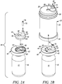
- a device is indicated generally by the reference numeral 10.
- the device 10 is a multiple dose vial.
- the vial 10 comprises a body 12 and a storage chamber 14 within the body for storing multiple doses of the substance therein.
- the storage chamber is a variable-volume storage chamber defined by a flexible and/or elastic pouch 16.
- a one-way valve 18 is connectable in fluid communication with a syringe 20 ( FIGS. 3-6 ).
- the one-way valve 18 (i) permits substance from the storage chamber 14 to flow therethrough and into the syringe 20 when connected in fluid communication therewith, and (ii) substantially prevents any fluid flow in a substantially opposite direction therethrough and into the storage chamber 14 to thereby maintain the substance sterile, aseptic and/or contamination free.
- the body 12 defines a side wall 22 (here cylindrical but can be another shape), an opening 24 at the base of the side wall, and an upper wall 26 enclosing the body 12 at the opposite end of the base.
- the upper wall 26 defines a filling port 28 extending through a central region thereof, and a connector 30 including a male Luer connector 32 formed on the outer end thereof, an approximately dome-shaped base 34 extending between the male Luer connector 32 and the upper wall 26, and a valve opening 36 extending through the connector for receiving the one-way valve 18.
- the vial 10 includes a variable-volume storage chamber, closure and one-way valve preassembly 38 that is received within and fixedly secured to the vial body 12 to form the multiple dose vial.
- the preassembly 38 comprises a closure 40 including a relatively rigid closure base 42 and a relatively flexible closure overlay 44 mounted on the closure base 42.
- the flexible closure overlay 44 defines a flexible base and sealing member 46, a penetrable filling portion or septum 48, a valve cover or member 50 of the one-way valve 18, and an approximately dome-shaped spring 52 extending between the valve member 50 and flexible base 46.
- the valve cover 50 is received within the valve opening 36 of the connector 30, and the dome-shaped spring 52 is received within the dome-shaped base 34 of the connector 30.
- the closure base 42 defines a filling inlet 54 that is aligned, e.g., axially, with the filling port 28 of the vial body 12 and opens into the variable-volume storage chamber 14 of the flexible pouch 16.
- the flexible pouch 16 and filling inlet 54 are integrally formed with the closure base 42.
- the closure base 42, filling inlet 54, and a preform (not shown) for the flexible pouch 16 are injection molded, and the pouch 16 is, in turn, blow molded from the injection molded preform, in accordance with the teachings of any of the following co-pending patent applications: U.S. Patent Application No.
- the closure base 42 defines a circular-shaped recess 56 that receives therein the flexible base and sealing member 46 of the closure overlay 44.
- the closure base 42 further defines an annular seal channel 58 spaced radially inwardly relative to the periphery of the circular-shaped recess 56.
- the flexible closure overlay 44 defines a corresponding peripheral seal 60 and an annular seal 62 spaced radially inwardly relative to the peripheral seal 60 and projecting axially therefrom.
- the annular seal 62 of the closure overlay 44 is received within the annular seal channel 58 of the closure base 42 to form a fluid-tight seal therebetween, and the peripheral seal 60 of the closure overlay 44 is received within the periphery of the recess 56 of the closure base 42 to form a fluid-tight seal therebetween.
- the closure base 42 further defines within the circular-shaped recess 56 a valve-receiving recess 64 aligned with the one-way valve 18, and a fluid-flow channel 66 extending between the storage chamber port 54 and the valve-receiving recess 64. As described further below, when the syringe 20 is fully connected to the connector 30, the one-way valve 18 is moveable from a first normally-closed position ( FIG.
- the vial body 12 defines a snap-fit protuberance 68 that is axially spaced adjacent to the upper wall 26 and extends annularly about the vial body. As can be seen, the side of the protuberance 68 opposite the upper wall 26 is tapered inwardly to allow the closure 40 to slide past the protuberance and into the assembled position as shown.
- the protuberance 68 engages the underside of the closure base 42 to form a compression seal between peripheral seal 60 and annular seal 62 of the flexible overlay 44 and the closure base 42, hermetically seal the variable-volume storage chamber 14 with respect to ambient atmosphere, and fixedly secure the closure base 42 and thus the preassembly 38 within the vial body 12.
- the components of the vial may take any of numerous different shapes and/or configurations capable of performing the function(s) of each such component as described herein.
- the septum 48 is penetrable by a needle, filling or injection member (not shown) for sterile or aseptically filling the storage chamber 14 with multiple doses of the substance to be dispensed.
- the septum 48 in some embodiments, is formed of a material that is sufficiently elastic to close itself after withdrawal of the needle, filling or injection member therefrom to thereby ensure that the head loss left by a residual penetration hole after the injection member is withdrawn prevents fluid ingress therethrough.
- the septum 48 may be resealed by a liquid sealant such as silicone or a silicone-based sealant, and/or the application of radiation or energy thereto to hermetically seal the substance within the storage chamber 14 from the ambient atmosphere and thereby maintain the sterility of the substance.
- a liquid sealant such as silicone or a silicone-based sealant
- the septum 48 may be penetrable for sterile filling the variable-volume storage chamber 14 and resealable, such as by the application of laser, other radiation, or thermal energy, to hermetically seal the filled substance within the storage chamber 14 in accordance with the teachings of any of the following patents and patent applications: U.S. Patent Application No. 12/254,789, filed October 20, 2008 , entitled "Container Having a Closure and Removable Resealable Stopper for Sealing a Substance Therein and Related Method," which, in turn, claims the benefit of U.S. Patent Application No.
- the septum 48 may be penetrable for sterile filling the variable-volume storage chamber 14 and resealable with a liquid sealant, such as a silicone sealant, to hermetically seal the filled substance within the storage chamber 14, in accordance with the teachings of any of the following patent applications: U.S. Patent Application No. 12/577,126, filed October 9, 2009 , entitled “Device with Co-Extruded Body and Flexible Inner Bladder and Related Apparatus and Method," which claims the benefit of similarly titled U.S. Provisional Patent Application No. 61/104,613, filed October 10, 2008 ; U.S. Patent Application No.
- the sealed empty chamber Prior to filling the variable-volume storage chamber 14, the sealed empty chamber may be sterilized by injecting a fluid sterilant therein, such as nitric oxide, with a needle, filling, or injection member through the penetrable and resealable portion 48, and the needle employed for injecting the fluid sterilant and/or the substance to be sterile filled into the variable-volume storage chamber 14 may be a self-opening and closing needle, in accordance with the teachings of any of the following co-pending patent applications: U.S. Patent Application No. 13/450,306, filed April 18, 2012 , entitled “Needle with Closure and Method," which claims the benefit of U.S. Provisional Patent Application No.
- the penetrable and resealable portion or septum may be penetrated and resealed, and the variable-volume storage chamber may be sterilized and sterile filled, by any of numerous different devices and methods that are currently known, or that later become known.
- the one-way valve 18 includes a relatively rigid valve seat 70 that is received within the flexible valve member or cover 50 and defines a normally closed, valve seam 72 therebetween.
- the valve seam 72 is axially-elongated and annular, but can have other shapes and configurations.
- the valve member 50 engages, and in some embodiments forms an interference fit with, the valve seat 70 to thereby form a fluid-tight seal in the normally closed position and, in turn, maintain the substance within the storage chamber 14 in a sterile and hermetically sealed condition.
- the valve 18 defines a valve opening pressure and remains in the normally closed position unless a pressure differential across the valve exceeds the valve opening pressure. When a pressure differential across the valve does exceed the valve opening pressure, the valve member 50 expands, e.g., radially, relative to or otherwise moves away from the valve seat 70 and opens the valve seam 72 therebetween.
- the valve opening pressure is defined, in part, as a function of the length of the engagement of the valve member 50 with the valve seat 70, i.e., the axial extent of the valve seam 72. The greater the length thereof, the greater the valve opening pressure.
- the valve seat 70 defines at least one elongated groove 71 therein.
- the valve member 50 need not be displaced at the groove(s) 71 for the fluid to flow. Accordingly, the length, and number, of the groove(s) 71 effectively reduces the length of the valve seam 72 and thus effectively reduces the valve opening pressure of the valve 18.
- the length and number of the groove(s) 71 are configured, in consideration of the properties of the valve member 50, e.g., its elasticity, thickness, shape, etc., such that a delivery device engaging the valve 18 and utilized in a normal manner, e.g., withdrawing a plunger from a barrel of a syringe engaging the valve, is capable of creating a pressure differential across the valve that exceeds the valve opening pressure, and this opens the valve seam 72.
- these features are configured to maintain a minimum valve opening pressure to prevent unintentional opening, as should be understood by one of ordinary skill in the pertinent art.
- the valve member 50', 150 may also define a substantially tapered cross-sectional shape moving in the direction from an inlet towards an outlet of the valve. This configuration requires progressively less energy to open the valve when moving from the interior, or inlet, toward the exterior, or outlet, of the valve.
- the valve seat 70', 170 may define an outer diameter that progressively or otherwise increases in the direction from the inlet towards the outlet of the valve, to provide the same or similar effect.
- the pressure is sufficient to open the valve at an inlet thereof, the pressure is sufficient to cause the downstream segments or portions of the valve member 50', 150 to progressively open and then close after passage of substance through the respective portion of the valve seam 72', 172 when moving in the direction from the inlet towards the outlet of the valve to dispense the dosage of substance.
- at any time when dispensing a dosage of substance at least one of the plurality of segments of the valve member 50 engages the valve seat 70 to maintain a fluid-tight seal across the valve 18, and thereby prevent ingress of fluid, germs, bacteria or other unwanted substances therethrough and into the variable-volume storage chamber 14.
- the valve 18 includes a substantially dome-shaped spring 52 formed of a resilient and/or elastomeric material.
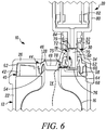
- the spring 52 permits the valve member 18 to move between an extended first position ( FIG. 5 ), wherein the valve member 50 is fully received within the valve opening 36 of the connector, and a depressed second position ( FIG. 6 ) wherein the valve member 50 is depressed or otherwise moved distally within the valve opening 36 and out of engagement with the interior surface 74 of the connector 30.
- the dome-shaped spring 52 normally biases the valve 18 in the direction from the second position toward the first position.
- the spring 52 also substantially prevents pressure created by inadvertently ejected air or other material from a syringe or other delivery device 20 connected to the valve 18 from moving the valve from the first position toward the second position.
- the interior surface 74 forming the valve opening 36 engages the valve member 50 or otherwise substantially prevents expansion or opening of the valve member 50 relative to the valve seat 70, and thus prevents the valve 18 from opening.
- the valve seam 72 is closed, thereby preventing the passage of the substance therethrough.
- the valve member 50 is disengaged from the interior surface 74 with sufficient space around it so that the valve 18 is free to open (and open the valve seam 72) when a pressure differential across the valve 18 exceeds the valve opening pressure to, in turn, permit expansion of the valve member 50 relative to the valve seat 70 and thereby allow the flow of substance from the variable-volume storage chamber therethrough.
- the flexible valve member 50 defines a base portion 76 that engages a distal base of the valve seat 70 to support the valve seat, e.g., axially, within the valve 18.
- the base portion 76 defines one or more valve inlet apertures 78 therethrough, in fluid communication with the normally closed valve seam 72, to permit fluid flow from the variable-volume storage chamber 14 and through the valve seam 72, when the valve 18 is in the second position and the pressure differential across the valve exceeds the valve opening pressure.
- the outlet end of the valve seat 70 defines a plurality of angularly spaced protuberances 79 thereon that engage a syringe connector 84 of the syringe 20 and permit the flow of fluid therebetween (between the protuberances 79) in order to allow fluid flow through the valve 18 and into the syringe 20.
- the syringe or other delivery device 20 is connected to the connector 30.
- the syringe 20 includes a barrel 80, a manually-engageable plunger 82 received within the barrel, and the connector 84 mounted at one end of the barrel and in fluid communication with the interior of the barrel.
- the vial connector 30 is a male Luer connector
- the syringe connector 84 is a female Luer connector.
- any of numerous different connectors for either the syringe or other delivery device, or the multiple dose vial or other device, that are currently known, or that later become known, may be used.
- the connector 84 of the syringe 20 engages the valve seat 70 and displaces the valve 18 from the first position toward the second position.
- the connector 30 and the valve 18 define a cavity 75 therebetween.
- the pressure of the air in the cavity 75 functions to further compress the flexible valve member 50 onto the valve seat 70, i.e., helping to keep the valve 18 closed, thereby further ensuring no entry of material through the valve 18 and into the storage chamber 14.
- the interior surface 74' of the connector 30' defines a substantially tapered cross-sectional shape moving in the direction from the dome shaped base 34' toward the Luer connector 32', thereby requiring relatively less movement (compared to embodiments where the interior surface 74' is not tapered) of the valve 18' in the direction from the first position toward the section position in order to disengage the interior surface 74' from the valve member 50'.
- the cavity 75' is larger in or to accommodate a greater volume of inadvertently ejected air, and further compress the valve 18'.
- the taper is also sufficient so that the valve member 50' can move away from the valve seat 70' and open the valve 18'.
- valve 18 when in the second position and upon withdrawal of the plunger 82 of the syringe 20, a vacuum or partial vacuum is created within the barrel of the syringe 20 which, in turn, creates a pressure differential across the valve 18.
- the pressure differential across the valve 18 exceeds the valve opening pressure, the valve seam 72 opens, and the substance within the variable-volume storage chamber 14 flows through the valve inlet aperture(s) 78 and, in turn, through the valve seam 72 and into the barrel of the syringe. Because the valve 18 is in the second position, the valve member 50 is permitted to move relative to the valve seat 70, e.g., radially, to allow the flow of the substance from the variable-volume storage chamber therethrough and into the syringe.
- valve member 50 because of the nature of the valve member 50, any ambient air or other fluid that could contaminate the interior of the valve or storage chamber is substantially prevented from flowing through the valve in the opposite direction, as discussed above. As a result, the interior of the valve and storage chamber can be maintained sterile, aseptic, and/or contamination free, as desired, throughout dispensing of dosages from the storage chamber.
- the pressure differential, if any, across the valve 18 decreases to than the valve opening pressure, the valve seam 72 closes (the valve member 50 moves back into engagement with the valve seat 70) and the flow of substance from the variable-volume storage chamber 14 through the valve 18 is terminated.
- the dome-shaped spring 52 drives the valve from the second position toward the first position where the interior surface 74 of the connector engages the valve member 50 and further prevents the possibility of the valve seam 72 opening and any fluid flow through the valve.
- the taper assists in guiding the valve 18 into the first position.
- the valve 18 permits substance from the variable-volume storage chamber 14 to flow through the one-way valve and into the delivery device connected in fluid communication therewith, but prevents the ingress of fluid in a substantially opposite direction into the variable-volume storage chamber. Consequently, the substance within the variable-volume storage chamber 14 is never exposed to the ambient atmosphere. When another dose of substance is needed from the vial, the same steps may be repeated.
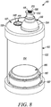
- FIGS. 8-10 another device is indicated generally by the reference numeral 110.
- the device 110 is substantially similar to the devices 10, 10' described above in connection with FIGS. 1-7 , and therefore like reference numerals preceded by the numeral "1" are used to indicate like elements.
- a primary difference of the device 110 in comparison to the device 10 is that a sliding seal or stopper 186 is received within the vial body 112 and is spaced relative to the one-way valve 118, wherein the variable-volume storage chamber 114 is defined between the sliding seal 186 and the one-way valve 118, as hereinafter described.
- the sliding seal 186 includes at least one, and in the embodiment shown, best seen in FIG. 9 , two axially spaced outer annular sealing members or portions 187 that sealingly engage the interior cylindrical wall of the vial body 112 to form a fluid-tight seal therebetween, but permit the sliding stopper to slide within the vial body.
- the sealing members or portions 187 may be formed integral with the sliding seal 186, such as by forming thereon annular protuberances, as shown, or may be formed by sealing members, such as o-rings or other sealing members, that are received within corresponding grooves or recesses formed in the sliding seal.
- a removable base closure 188 encloses the opening 124 at the base of the vial body 112, and includes one or more vent apertures 189 to prevent the formation of a vacuum between the sliding seal 186 and the base closure 188, and otherwise to allow the sliding seal 186 to travel through the vial body 112 upon dispensing of the substance from the vial 110, as described further below.
- the sliding seal 186 and the manner in which it cooperates with the vial body 112 to define the variable-volume storage chamber 114 may be the same as or substantially similar to that disclosed in any of the following patents and patent applications: U.S. Patent Application No. 13/219,597, filed August 26, 2011 , entitled “Laterally-Actuated Dispenser with One-Way Valve For Storing and Dispensing Substances," which is a continuation of U.S. Patent Application No. 12/710,516, filed February 23, 2010 , entitled “Laterally-Actuated Dispenser with One-Way Valve for Storing and Dispensing Metered Amounts of Substances," now U.S. Patent No.
- the closure 140 including the closure base 142, is integrally formed with the upper side of the vial body 112, and the flexible closure overlay 144 is mounted thereon in the same manner as in the embodiments described above in connection with FIGS. 1-7 .
- a vial cap 127 defining the upper wall 126 and connector 130, mounts atop the closure overlay 144 to sealingly enclose the body 112 at the upper side of the vial 110.
- the vial cap 127 further defines the snap-fit protuberance 168 that is axially spaced adjacent to the upper wall 126 and extends annularly about the cap 127.
- the side of the protuberance 168 opposite the upper wall 126 is tapered inwardly to allow the closure base 142 of the vial body 112 to slide over the protuberance and snap into the assembled position as shown.
- the protuberance 168 engages the underside of the closure base 142 to form a compression seal between the peripheral seal 160 and annular seal 162 of the flexible overlay 144 and the closure base 142, hermetically seal the variable-volume storage chamber with respect to the ambient atmosphere, and fixedly secure the vial cap 127 onto the vial body 112.
- the flexible closure overlay 144 defines the flexible base and sealing member 146, the penetrable and resealable portion or septum 148, the valve cover or member 150 of the one-way valve 118, and the approximately dome-shaped spring 152.
- the closure base 142 defines, within the circular-shaped recess 156, the valve-receiving recess 164 aligned, e.g., axially, with the one-way valve 118, and at least one fluid-flow aperture 190 within the valve-receiving recess 164.
- the penetrable and resealable portion or septum 148 is penetrable by a needle, filling or injection member (not shown) for sterile or aseptically filling the storage chamber 114 with multiple doses of the substance to be dispensed.
- the septum 148 can be formed of a material that is sufficiently elastic to close itself after withdrawal of the needle, filling or injection member therefrom to thereby ensure that the head loss left by a residual penetration hole after the injection member is withdrawn prevents fluid ingress therethrough.
- the septum 148 may be resealed by a liquid sealant, such as silicone or a silicone-based sealant, and/or the application of radiation or energy thereto to hermetically seal the substance within the storage chamber 114 from the ambient atmosphere and thereby maintain the sterility of the substance.
- the septum 148 may be penetrable for sterile filling the variable-volume storage chamber and resealable, such as by the application of laser, other radiation, or thermal energy, to hermetically seal the filled substance within the storage.
- the septum 148 may be penetrable for sterile filling the variable-volume storage chamber, and resealable with a liquid sealant, such as a silicone sealant, to hermetically seal the filled substance within the storage chamber.
- the sealed empty chamber Prior to filling the variable-volume storage chamber, the sealed empty chamber may be sterilized by injecting a fluid sterilant therein, such as nitric oxide, with a needle, filling or injection member through the penetrable and resealable portion 148, and the needle employed for injecting the fluid sterilant and/or the substance to be sterile filled into the variable-volume storage chamber may be a self opening and closing needle.
- a fluid sterilant therein such as nitric oxide
- the one-way valve 118 includes a relatively rigid valve seat 170 that is received within the flexible valve member or cover 150 and defines a normally closed, valve seam 172 therebetween.
- the valve member 150 engages, and in alternative embodiments forms an interference fit with, the valve seat 170 to thereby form a fluid-tight seal in the normally closed position and, in turn, maintain the substance within the storage chamber 114 in a sterile and hermetically sealed condition.
- the valve 118 defines a valve opening pressure, and remains in the normally closed position unless a pressure differential across the valve exceeds the valve opening pressure. When a pressure differential across the valve does exceed the valve opening pressure, the valve member 150 expands, e.g., radially, relative to or otherwise moves away from the valve seat 170 and opens the valve seam 172 therebetween.
- the valve 118 includes a substantially dome-shaped spring 152 formed of a resilient and/or elastomeric material. Similar to the embodiment described above, the spring 152 permits the valve member 118 to move between an extended first position wherein the valve member 150 is fully received within the valve opening 136 of the connector 130, and a depressed second position wherein the valve member 150 is depressed or otherwise moved distally within the valve opening 136 and out of engagement with the connector 130. As can be seen, the dome-shaped spring 152 normally biases the valve 118 in the direction from the second position toward the first position.
- valve opening 136 When in the first position, the interior surface 174 forming the valve opening 136 engages the valve member 150 or otherwise substantially prevents radial expansion or opening of the valve member 150 relative to the valve seat 170, and thus prevents the valve 118 from opening.
- the annular valve seam 172 is closed.
- the valve member 150 When in the second position, the valve member 150 is disengaged from the connector interior surface 174 with sufficient space around it so that the valve 118 is free to open (and open the valve seam 172) when a pressure differential across the valve 118 exceeds the valve opening pressure to, in turn, permit expansion of the valve member 150 relative to the valve seat 170 and thereby allow the flow of substance from the variable-volume storage chamber therethrough.
- the flexible valve member 150 defines a base portion 176 that engages an inner end of the valve seat 170 to support the valve seat within the valve 118.
- the base portion 176 defines one or more valve inlet apertures 178 therethrough in fluid communication with the normally closed annular valve seam 172 to permit fluid flow from the variable-volume storage chamber 114 through the valve 118 when in the second position and the pressure differential across the valve exceeds the valve opening pressure.
- the outlet end of the valve seat 170 defines a plurality of angularly spaced protuberances 179 thereon that engage a syringe connector 84 of the syringe 20 but permit the flow of fluid therebetween (between the protuberances 179) in order to allow fluid flow through the valve 118 and into the syringe 20.
- the syringe or other delivery device 20 is connected to the connector 130.
- the connector 84 of the syringe engages the valve seat 170 and displaces the valve 118 from the first position to the second position.
- a vacuum or partial vacuum is created within the barrel of the syringe 20 which, in turn, creates a pressure differential across the valve 118.
- valve seam 172 opens and the substance within the variable-volume storage chamber flows through the fluid flow aperture(s) 190 and subsequently through the valve inlet aperture(s) 178 and, in turn, through the valve seam 172 and into the barrel of the syringe 20.
- suction forces exerted on the sliding seal 186 caused by the exit of the substance from the storage chamber 114 cause the seal to move or slide within the vial body 112 toward the one-way valve 118 to reduce the volume of the variable-volume storage chamber 114 by substantially the same volume of substance dispensed.
- the pressure differential, if any, across the valve 118 decreases to less than the valve opening pressure, and the flow of substance from the variable-volume storage chamber 114 through the valve 118 is terminated.
- the dome-shaped spring 152 drives the valve from the second position toward the first position where the interior surface 174 of the connector engages the valve member 150 and further prevents the possibility of any fluid flow through the valve.
- the same steps may be repeated.
- the interior of the valve and storage chamber can be maintained sterile, aseptic, and/or contamination free, as desired, throughout dispensing of dosages from the storage chamber, as explained in the embodiment described above.
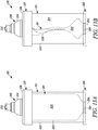
- FIGS. 11-13B another embodiment of the device is indicated generally by the reference numeral 210.
- the device 210 is substantially similar to the devices 10, 10' and 110 described above in connection with FIGS. 8-10 , and therefore like reference numerals preceded by the numeral "2" are used to indicate like elements. For simplicity, the following description is directed to the differences in the variable-volume storage chamber 214 within the vial body 212.
- the vial 210 includes a collapsible flexible bladder 291 integrally formed with, and projecting from, a base closure 288.
- the base closure 288 sealingly encloses the base of the vial body 212, thereby sealing off the storage chamber 214 from the ambient atmosphere, and the flexible bladder 291 projects within the vial body 212 toward the opposing valve end of the vial 210.
- the bladder 291 may extend from the closure 240 toward the base end of the vial 210.
- the variable-volume storage chamber 214 is defined between the flexible bladder 291 and the side wall 222 of the vial body 212.
- the flexible bladder 291 has a bladder wall 292 defining a bladder cavity 293 therein.
- the flexible bladder 291 has a substantially central opening 294 at a base end thereof, defining an open port 295 in the base closure 288 in fluid communication with the bladder cavity 293.
- the base closure 288 and a preform (not shown) for the flexible bladder 291 are injection molded, and the bladder 291 is, in turn, blow molded from the injection molded preform.
- the elastic bladder 291 is sealed and is compressible and expandable.
- the flexible bladder 291 is tubular in configuration and defines an external diameter dimensioned to fit within the vial body 212 when in the fully expanded state as shown in FIGS. 12A and 13A .
- the bladder 291 can have other configurations capable of performing the functions of the bladder as described herein.
- the wall 292 of the bladder 291 defines a shape or morphology substantially the same as that of the vial body side wall 222 so that it conforms to and contacts the vial body side wall 222 throughout the interface of these two components.
- the empty variable-volume storage chamber is substantially airless.
- the storage chamber 214 is sterile or aseptically filled with multiple doses of the substance to be dispensed via the penetrable and resealable portion or septum 248, in similar manner as in the embodiments described above.
- the bladder 291 collapses, as shown in FIGS. 12B and 13B and explained further below. Thereafter, when the connector 84 of the syringe 20 engages the valve seat 270, displaces the valve 218 from the first position to the second position, and the plunger 82 is subsequently withdrawn, the substance within the variable-volume storage chamber 214 flows through the one-way valve 218 and into the barrel of the syringe 20.
- the bladder 291 inflates accordingly, as also explained further below. As shown in FIGS 12A and 13A , the bladder 291 is expandable until the bladder wall 292 substantially conforms to the morphology of the side wall 222 of the vial body 212, to thereby eliminate any ullage or dead space and dispense substantially all of the substance in the storage chamber 214.
- the sealed interior of the vial body 212 comprised of the variable-volume storage chamber 214 and the flexible bladder 291, defines a constant volume.
- the volume of the flexible bladder cavity 293 substantially correspondingly decreases, and likewise, as the volume of the storage chamber 214 decreases, the volume of the flexible bladder cavity 293 substantially correspondingly increases.
- the flexible bladder 291 is assembled into the vial body 212 in its fully expanded state. Any air in the vial body 212 is thus displaced out the rear of the vial body 212 during assembly. Thereafter, when the sealed variable-volume storage chamber 214 is filled with a desired volume of substance, i.e., when substance is filled between the side wall 222 of the vial body 212 and the wall 292 of the flexible bladder 291, the flexible bladder 291 collapses accordingly, where a substantially equal volume of air flows out of the bladder cavity 293, through the open port 295, and into the ambient atmosphere.
- variable-volume storage chamber 214 when a dose of the substance within the variable-volume storage chamber 214 is dispensed therefrom, through the valve 218, the pressure differential between the variable-volume storage chamber 214 and the atmosphere causes a substantially equal volume of air to flow into the bladder cavity 293, through the port 295, and re-expand the bladder.
- a one-way valve is inserted into the open port 295 of the base closure 288 after the variable-volume storage chamber 214 is filled with the substance and the bladder 291 is collapsed. The one-way valve allows air to flow into the bladder cavity 293 with each dose of substance dispensed, but substantially prevents air from flowing out of the cavity.
- the one-way valve may take the form of any of numerous different one-way valves, that are currently known, or that later become known, for performing the function of the one-way valve as described herein, including without limitation a check valve, a duckbill valve, a flapper valve or an umbrella valve.
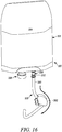
- FIGS. 14-16 another device is indicated generally by the reference numeral 310.
- the device 310 is substantially similar to the devices 10, 10', 110 and 210 described above in connection with FIGS. 1-13B , and therefore like reference numerals preceded by the numeral "3" are used to indicate like elements.
- a primary difference of the device 310 in comparison to the device 10 is that the body 312 is a collapsible bladder, bag or pouch, rather than a rigid vial body 12, as hereinafter described.
- the collapsible pouch 312 defines the variable-volume storage chamber 314 therein. As shown best in FIGS. 14 and 15 , the collapsible pouch 312 includes a filling port 328 and an outlet connector 330. In the illustrated embodiment, the filling port 328 and the connector 330 are both located at one end of the pouch 312. However, as should be recognized by those of ordinary skill in the pertinent art, the filling port and connector may equally be located at opposing ends of the pouch 312. The filling port may also be on the pouch 312 itself.
- the filling port 328 is utilized for sterile or aseptically filling the storage chamber 314 therethrough with multiple doses of the substance to be dispensed, and the outlet connector 330 is utilized for dispensing doses of substance therefrom. With each dose of substance dispensed, the pouch 312 is collapsible by approximately the same volume.
- the particular filling port 328 shown includes a penetrable and resealable portion or septum 348.
- the septum 348 is penetrable by a needle, filling or injection member (not shown) for sterile or aseptically filling the storage chamber 314 with multiple doses of the substance to be dispensed.
- the septum 348 in some embodiments, is formed of a material that is sufficiently elastic to close itself after withdrawal of the needle, filling or injection member therefrom to thereby ensure that the head loss left by a residual penetration hole after the filling or injection member is withdrawn prevents liquid ingress therethrough.
- the septum 348 may be resealed by a liquid sealant, such as silicone or a silicone-based sealant, and/or the application of radiation or energy thereto in order to hermetically seal the substance within the storage chamber 314 to prevent ingress of air or contaminants from the ambient atmosphere or environment and thereby maintain the sterility thereof.
- the septum 348 may be penetrable for sterile filling the variable-volume storage chamber and resealable, such as by the application of radiation or energy, e.g., laser radiation or thermal energy, to hermetically seal the filled substance within the storage chamber.
- the septum 348 may be penetrable for sterile filling the variable-volume storage chamber 314, and resealable with a liquid sealant, such as a silicone sealant, to hermetically seal the filled substance within the storage chamber.
- the outlet connector 330 includes a one-way valve 318 therein, similar in design and function to the one way valves 18, 18', 118, and 218 of the above-described embodiments, and a Luer connector 332 formed at the outer end thereof.
- the one-way valve 318 is connectable in fluid communication with a syringe or other delivery device 320 via the Luer connector 332.
- the one-way valve 318 (i) permits substance from the storage chamber 314 to flow therethrough and into the dispensing member 320 when connected in fluid communication therewith, and (ii) substantially prevents any fluid flow in a substantially opposite direction therethrough and into the storage chamber 314 to thereby maintain the substance sterile, aseptic, and/or contamination free.
- the illustrated delivery device 320 includes a flexible tube 380 having a connector 384 at an inlet end thereof, and a pump 382 ( FIG. 16 ) operatively associated with the tube 380.
- the connector 384 of the flexible tube 380 is connected to the pouch outlet connector 330 ( FIGS. 15 , 16 ).
- the Luer connector 332 of the outlet connector 330 is a male Luer connector
- the flexible tube connector 384 is a female Luer connector.
- any of numerous different connectors for either the delivery device or the pouch that are currently known, or that later become known, may be used.
- the connector 384 of the flexible tube 380 displaces the valve 318 from the first position to the second position, similarly to as described above with respect to the previous embodiments.
- operation of the pump 382 creates a pressure differential across the valve 318 exceeding the valve opening pressure, thereby opening the valve 318 and allowing the substance to flow from the storage chamber 314, through the valve 318, and through the tube 380.
- any ambient air or other fluid that could contaminate the interior of the valve 318 or storage chamber 314 is substantially prevented from flowing through the valve in the opposite direction.
- the interior of the valve and storage chamber can be maintained sterile, aseptic, and/or contamination free, as desired, throughout dispensing of dosages from the storage chamber.
- any of numerous different pumps or actuators may be utilized with the flexible tube to draw fluid out of the storage chamber and through the one-way valve.
- a peristaltic pump may be utilized.
- a syringe can be connected to the end of the tube 380 to withdraw fluid from the pouch 312.
- the components of the vial may be made of any of numerous different materials or combinations of materials that are currently known, or that later become known for performing the function(s) of each such component.
- the components of the vial may take any of numerous different shapes and/or configurations, and may be manufactured in accordance with any of numerous different methods or techniques that are currently known, or later become known.
- the penetrable and resealable portion may be located at a different part of the vial rather than the flexible closure overlay at the top end thereof.
- the seal or the base closure may include the penetrable and resealable septum, respectively.
- the variable-volume storage chamber may be filled in like manner as described above, but from the base end of a vial rather than from the opposing dispensing valve end.
- a sliding seal or base closure and flexible bladder including a penetrable and resealable septum would define a universal bottom which may be utilized with any vial having an open end at one end and a dispensing port and/or valve at the opposing end.
- Such a setup would require no modification to the vial. Rather, after assembling the sliding seal or base closure and flexible bladder in sealing engagement with the vial, it would be aseptically fillable via the septum therein, and define a variable-volume storage chamber resulting from the functionality of the sliding seal or the flexible bladder.
- the storage chamber may be sterile or aseptic filled through a non-piercing filling cannula or probe that is connectable in fluid communication with a one-way valve mounted on the vial body or otherwise on the device, e.g., on the sliding seal or base closure, in fluid communication with the storage chamber.
- the filling cannula and/or one-way valve may be constructed in accordance with the teachings of any of the following patents and patent applications: U.S. Patent Application No. 12/534,730, filed August 3, 2009 , entitled "Lyophilization Method and Device," now U.S. Patent No.
- the storage chamber may be filled via a connector.
- a sterile or aseptic connector may be constructed in accordance with the teachings of any of the following patents and patent applications: U.S. Provisional Patent Application No. 61/625,663, filed April 17, 2012 , entitled “Self Closing Connector," similarly titled U.S. Provisional Patent Application No. 61/635,258, filed April 18, 2012 ; U.S. Provisional Patent Application No. 61/641,248, filed May 1, 2012 , entitled “Device for Connecting or Filling and Method;" and U.S. Patent Application No.
- the vial or other device embodying the present invention also may be used to store and dispense any of numerous different types of fluids or other substances for any of numerous different applications that are currently known, or later become known.
- the storage chamber need not be a variable-volume storage chamber.
- the storage chamber defines a substantially fixed volume, but includes a sterile filter, such as a micro-filter of a type known to those of ordinary skill in the pertinent art, that is coupled in fluid communication between the storage chamber and ambient atmosphere to allow air to flow into the storage chamber, but that sterilizes any such air that flows therethrough in order to maintain the interior of the variable-volume storage chamber sterile. Accordingly, this detailed description of embodiments is to be taken in an illustrative, as opposed to a limiting sense.
Landscapes
- Health & Medical Sciences (AREA)
- General Health & Medical Sciences (AREA)
- Veterinary Medicine (AREA)
- Public Health (AREA)
- Life Sciences & Earth Sciences (AREA)
- Animal Behavior & Ethology (AREA)
- Pharmacology & Pharmacy (AREA)
- Hematology (AREA)
- Engineering & Computer Science (AREA)
- Heart & Thoracic Surgery (AREA)
- Biomedical Technology (AREA)
- Anesthesiology (AREA)
- Vascular Medicine (AREA)
- Mechanical Engineering (AREA)
- Pulmonology (AREA)
- Medical Preparation Storing Or Oral Administration Devices (AREA)
- Physics & Mathematics (AREA)
- Fluid Mechanics (AREA)
- Infusion, Injection, And Reservoir Apparatuses (AREA)
- Acyclic And Carbocyclic Compounds In Medicinal Compositions (AREA)
- Display Devices Of Pinball Game Machines (AREA)
Claims (14)
- Vorrichtung (10, 10', 110, 210, 310) zum Speichern mehrerer Dosen einer Substanz, die in eine oder mehr Spritzen oder andere Verabreichungsvorrichtungen (20, 320) abgegeben werden soll, umfassend:einen Körper (12, 12', 112, 212, 312);eine Speicherkammer (14, 14', 114, 214, 314) innerhalb des Körpers (12, 12', 112, 212, 312) zum Speichern mehrerer Dosen der Substanz darin; undein Ventil (18, 18', 118, 218, 318), das mit einer Spritze oder einer anderen Verabreichungsvorrichtung (20, 320) in Fluidverbindung verbindbar ist, zwischen ersten und zweiten Positionen beweglich ist und eine geschlossene Position hat, die verhindert, dass Substanz dort hindurch läuft, und eine offene Position aufweist, die erlaubt, dass Substanz hindurch läuft;dadurch gekennzeichnet, dass
das Ventil ein Einwegventil (18, 18', 118, 218, 318) ist;
in der ersten Position eine Fläche (74, 74', 174) der Vorrichtung (10, 10', 110, 210, 310) mit dem Einwegventil (18, 18', 118, 218, 318) in Eingriff kommt oder auf andere Weise im Wesentlichen verhindert, dass das Einwegventil (18, 18', 118, 218, 318) sich in die offene Position öffnet, und Substanz von der Speicherkammer (14, 14', 114, 214, 314) nicht hindurch laufen kann, und in der zweiten Position das Einwegventil (18, 18', 118, 218, 318) ausreichend von der Fläche (74, 74', 174) der Vorrichtung (10, 10', 110, 210, 310) gelöst oder beabstandet ist, um zu ermöglichen, dass sich das Ventil (18, 18', 118, 218, 318) in die offene Position öffnet, so dass das Einwegventil (18, 18', 118, 218, 318) erlaubt, dass Substanz von der Speicherkammer dort hindurch und in die Spritze oder die andere Verabreichungsvorrichtung (20, 320) fließt, die damit in Fluidverbindung verbunden ist. - Vorrichtung (10, 10', 110, 210, 310) nach Anspruch 1, wobei die Speicherkammer (14, 14', 114, 214, 314) eine Speicherkammer mit variablem Volumen umfasst.
- Vorrichtung (10, 10', 110, 210, 310) nach Anspruch 2, wobei(i) der Körper (12, 12', 112, 212, 312) ein flexibler und zusammenlegbarer Körper (312) ist und die Speicherkammer (14, 14', 114, 214, 314) mit variablem Volumen darin definiert;(ii) wobei der Körper (12, 12', 112, 212, 312) im Wesentlichen steif ist (212) und die Speicherkammer (14, 14', 114, 214, 314) mit variablem Volumen durch eine flexible Blase (291) definiert ist, die innerhalb des steifen Körpers (212) aufgenommen ist; oder(iii) wobei der Körper (12, 12', 112, 212, 312) eine Verschiebedichtung (186) umfasst, die darin aufgenommen ist und relativ zu dem Einwegventil (18, 18', 118, 218, 318) beabstandet ist, wobei die Speicherkammer (14, 14', 114, 214, 314) mit variablem Volumen innerhalb des Körpers zwischen dem Verschiebeventil (186) und dem Einwegventil (18, 18', 118, 218, 318) definiert ist.
- Vorrichtung (10, 10', 110, 210, 310) nach Anspruch 3, wobei der Körper eine Verschiebedichtung (186) umfasst, die darin aufgenommen ist und relativ zu dem Einwegventil (18, 18', 118, 218, 318) beabstandet ist, wobei die Speicherkammer (14, 14', 114, 214, 314) mit variablem Volumen innerhalb des Körpers (12, 12', 112, 212, 312) zwischen dem Verschiebeventil (186) und dem Einwegventil definiert ist; und
wobei die Verschiebedichtung (186) einen durchdringbaren und wiederverschließbaren Abschnitt (48, 148, 248, 348) umfasst, der durch ein Nadel-, Füll- oder Injektionselement zum Füllen der Speicherkammer (14, 14', 114, 214, 314) mit variablem Volumen mit Substanz durchdringbar ist und wiederverschließbar ist, um eine resultierende Durchdringungsöffnung in dem Abschnitt (48, 148, 248, 348) hermetisch abzuschließen. - Vorrichtung (10, 10', 110, 210, 310) nach Anspruch 1, wobei die Vorrichtung einen durchdringbaren und wiederverschließbaren Abschnitt (48, 148, 248, 348) umfasst, der durch ein Nadel-, Füll- oder Injektionselement zum Füllen der Speicherkammer (14, 14', 114, 214, 314) mit abzugebender Substanz durchdringbar ist und wiederverschließbar ist, um eine resultierende Durchdringungsöffnung in dem Abschnitt (48, 148, 248, 348) hermetisch abzuschließen.
- Vorrichtung (10, 10', 110, 210, 310) nach Anspruch 1, wobei das Einwegventil (18, 18', 118, 218, 318) normalerweise in einer Richtung von der zweiten Position zu der ersten Position hin vorgespannt ist.
- Vorrichtung (10, 10', 110, 210, 310) nach Anspruch 6, die des Weiteren eine Feder (52, 152) umfasst, die normalerweise das Einwegventil (18, 18', 118, 218, 318) in einer Richtung von der zweiten Position zu der ersten Position hin vorspannt.
- Vorrichtung (10, 10', 110, 210, 310) nach Anspruch 1, wobei das Einwegventil (18, 18', 118, 218, 318) einen Ventilsitz (70, 70', 170, 270) und ein Ventilelement (50, 150) umfasst, das normalerweise mit dem Ventilsitz (70, 70', 170, 270) in Eingriff ist, um die geschlossene Position zu definieren, wobei das Ventilelement relativ zum Ventilsitz (70, 70', 170, 270) beweglich ist, wenn ein Druckunterschied über das Einwegventil (18, 18', 118, 218, 318) einen Ventilöffnungsdruck davon übersteigt, und in der ersten Position die Fläche (74, 74', 174) der Vorrichtung (10, 10', 110, 210, 310) im Wesentlichen eine Bewegung des Ventilelements (50, 150) relativ zum Ventilsitz (70, 70', 170, 270) verhindert, und in der zweiten Position das Ventilelement (50, 150) ausreichend von der Fläche gelöst ist (74, 74', 174) um eine Bewegung des Ventilelements (50, 150) relativ zum Ventilsitz (70, 70', 170, 270) zu erlauben.
- Vorrichtung (10, 10', 110, 210, 310) nach Anspruch 8, wobei der Ventilsitz (70, 70', 170, 270) so ausgebildet ist, dass die Spritze oder die andere Verabreichungsvorrichtung (20, 320) mit dem Ventilsitz in Eingriff ist (70, 70', 170, 270), wenn sie mit der Vorrichtung (10, 10', 110, 210, 310) verbunden ist und das Ventil (18, 18', 118, 218, 318) in einer Richtung von der ersten Position zur zweiten Position hin bewegt.
- Vorrichtung (10, 10', 110, 210, 310) nach Anspruch 9, die des Weiteren eine Verbindungseinrichtung (30, 30', 130, 330) umfasst, die sich stromabwärts eines Auslasses des Einwegventils (18, 18', 118, 218, 318) befindet, wobei die Verbindungseinrichtung (30, 30', 130, 330) angepasst ist, die Spritze oder die andere Verabreichungsvorrichtung (20, 320) damit zu verbinden, und die Verbindung der Spritze oder der anderen Verabreichungsvorrichtung (20, 320) bewirkt, dass sich das Ventil (18, 18', 118, 218, 318) in einer Richtung von der ersten Position in die zweite Position bewegt.
- Verfahren, das die folgenden Schritte umfasst:i. Speichern mehrerer Dosen einer auszugebenden Substanz in einer Speicherkammer (14, 14', 114, 214, 314) einer Vorrichtung (10, 10', 110, 210, 310) und Abdichten der gespeicherten mehreren Dosen gegen die Umgebungsatmosphäre;ii. Verbinden einer Spritze oder einer anderen Verabreichungsvorrichtung (20, 320) in Fluidverbindung mit einem Einwegventil (18, 18', 118, 218, 318) in Fluidverbindung mit der Speicherkammer (14, 14', 114, 214, 314);iii. Bewegen des Einwegventils (18, 18', 118, 218, 318) aus (i) einer ersten Position, in der eine Fläche (74, 74', 174) der Vorrichtung (10, 10', 110, 210, 310) mit dem Einwegventil (18, 18', 118, 218, 318) in Eingriff kommt oder auf andere Weise im Wesentlichen verhindert, dass das Einwegventil (18, 18', 118, 218, 318) sich in eine offene Position öffnet, wobei Substanz dort hindurch laufen kann, in (ii) eine zweite Position, in der das Einwegventil (18, 18', 118, 218, 318) ausreichend von der Fläche (74, 74', 174) der Vorrichtung (10, 10', 110, 210, 310) gelöst oder beabstandet ist, um zu ermöglichen, dass sich das Ventil in die offene Position öffnet, und dadurch Substanz dort hindurch laufen kann;iv. Ausgeben einer Dosis von Substanz aus der Speicherkammer (14, 14', 114, 214, 314) durch das Einwegventil (18, 18', 118, 218, 318) und in die Spritze oder die andere Verabreichungsvorrichtung (20, 320);v. im Wesentlichen Verhindern, dass Umgebungsfluid während Schritt iv durch das Einwegventil (18, 18', 118, 218, 318) und in die Speicherkammer (14, 14', 114, 214, 314) läuft; undvi. Wiederholen der Schritte ii bis v mit derselben Vorrichtung (10, 10', 110, 210, 310).
- Verfahren nach Anspruch 11, wobei Schritt (iv) umfasst: das Schaffen von zumindest einem teilweisen Vakuum in der Spritze oder der anderen Verabreichungsvorrichtung (20, 320) und das Schaffen eines Druckunterschieds über das Einwegventil (18, 18', 118, 218, 318), die einen Ventilöffnungsdruck davon übersteigt.
- Verfahren nach Anspruch 11, wobei Schritt (iii) während oder nach Schritt (ii) durchgeführt wird.
- Verfahren nach Anspruch 11, das des Weiteren umfasst, die Substanz in der Speicherkammer (14, 14', 114, 214, 314) über zumindest die Schritte (i) bis (v) hermetisch gegen die Umgebungsatmosphäre abgeschlossen und/oder in steriler oder aseptischer Atmosphäre aufzubewahren.
Applications Claiming Priority (2)
| Application Number | Priority Date | Filing Date | Title |
|---|---|---|---|
| US201261587525P | 2012-01-17 | 2012-01-17 | |
| PCT/US2013/021998 WO2013109794A1 (en) | 2012-01-17 | 2013-01-17 | Multiple dose vial and method |
Publications (3)
| Publication Number | Publication Date |
|---|---|
| EP2804645A1 EP2804645A1 (de) | 2014-11-26 |
| EP2804645A4 EP2804645A4 (de) | 2015-06-03 |
| EP2804645B1 true EP2804645B1 (de) | 2017-04-12 |
Family
ID=48779152
Family Applications (1)
| Application Number | Title | Priority Date | Filing Date |
|---|---|---|---|
| EP13738633.0A Not-in-force EP2804645B1 (de) | 2012-01-17 | 2013-01-17 | Mehrfachdosierungsfläschchen und verfahren |
Country Status (11)
| Country | Link |
|---|---|
| US (2) | US9801787B2 (de) |
| EP (1) | EP2804645B1 (de) |
| JP (1) | JP6129208B2 (de) |
| KR (1) | KR101740238B1 (de) |
| CN (2) | CN109431802A (de) |
| BR (1) | BR112014017580A8 (de) |
| CA (1) | CA2862241C (de) |
| IN (1) | IN2014DN06816A (de) |
| MX (1) | MX2014008698A (de) |
| RU (1) | RU2618474C2 (de) |
| WO (1) | WO2013109794A1 (de) |
Cited By (1)
| Publication number | Priority date | Publication date | Assignee | Title |
|---|---|---|---|---|
| EP3984515A1 (de) * | 2020-10-15 | 2022-04-20 | Klim-Loc, LLC | Vorrichtungen zur nadellosen und genadelten extraktion von inhalt aus phiolen |
Families Citing this family (51)
| Publication number | Priority date | Publication date | Assignee | Title |
|---|---|---|---|---|
| US7547300B2 (en) | 2006-04-12 | 2009-06-16 | Icu Medical, Inc. | Vial adaptor for regulating pressure |
| WO2010022095A1 (en) | 2008-08-20 | 2010-02-25 | Icu Medical, Inc. | Anti-reflux vial adaptors |
| JP5829608B2 (ja) | 2009-07-29 | 2015-12-09 | アイシーユー・メディカル・インコーポレーテッド | 流体移行デバイスおよびその使用方法 |
| JP6541349B2 (ja) | 2011-08-18 | 2019-07-10 | アイシーユー・メディカル・インコーポレーテッド | 圧力調節バイアルアダプタ |
| US9849067B2 (en) | 2011-12-21 | 2017-12-26 | Berry Plastics Corporation | Pediatric dosing dispenser |
| US9156569B2 (en) * | 2011-12-21 | 2015-10-13 | Berry Plastics Corporation | Pediatric dosing dispenser |
| KR102481494B1 (ko) | 2011-12-22 | 2022-12-26 | 아이씨유 메디칼 인코퍼레이티드 | 의료용 유체 전달 시스템, 유체 전달 방법, 전자 의료용 유체 전달 시스템, 및 전자 의료용 유체 전달 시스템 이용 방법 |
| EP2802377B1 (de) | 2012-01-13 | 2016-12-07 | ICU Medical, Inc. | Druckregelnde phiolenadapter und verfahren |
| AU2013204180B2 (en) | 2012-03-22 | 2016-07-21 | Icu Medical, Inc. | Pressure-regulating vial adaptors |
| US9089475B2 (en) | 2013-01-23 | 2015-07-28 | Icu Medical, Inc. | Pressure-regulating vial adaptors |
| ES2966008T3 (es) | 2013-01-23 | 2024-04-17 | Icu Medical Inc | Adaptadores de vial de regulación de presión |
| US9415885B2 (en) | 2013-03-15 | 2016-08-16 | Dr. Py Institute Llc | Device with sliding stopper and related method |
| JP6691041B2 (ja) | 2013-06-18 | 2020-04-28 | イネイブル インジェクションズ、インコーポレイテッド | バイアル移送と注射の器具と方法 |
| AU2014290124B2 (en) | 2013-07-19 | 2019-05-09 | Icu Medical, Inc. | Pressure-regulating fluid transfer systems and methods |
| WO2015061693A1 (en) | 2013-10-24 | 2015-04-30 | Trustees Of Boston University | Infusion system employing an infusion set for preventing mischanneling of multiple medicaments |
| CA2931195C (en) | 2013-11-25 | 2019-09-24 | Icu Medical, Inc. | Methods and systems for filling iv bags with therapeutic fluid |
| CA2953229C (en) | 2014-06-20 | 2024-01-02 | Icu Medical, Inc. | Pressure-regulating vial adaptors |
| US10500132B2 (en) | 2015-01-07 | 2019-12-10 | Dr. Py Instittue, Llc | Pouch with sealed fitment and method |
| US10182969B2 (en) * | 2015-03-10 | 2019-01-22 | Regeneron Pharmaceuticals, Inc. | Aseptic piercing system and method |
| US11224690B2 (en) * | 2015-04-28 | 2022-01-18 | Sanofi-Aventis Deutschland Gmbh | Flexible container for an injection device |
| US20160361232A1 (en) * | 2015-06-11 | 2016-12-15 | Tokitae Llc | Packaging Multi-Monodose Containers |
| EP3319662B1 (de) | 2015-07-08 | 2023-09-13 | Trustees of Boston University | Infusionssystem und komponenten davon |
| JP6710758B2 (ja) | 2015-12-04 | 2020-06-17 | アイシーユー・メディカル・インコーポレーテッド | 医療用流体を移送するための電子式医療用流体移送装置 |
| EP4043001A1 (de) | 2016-01-29 | 2022-08-17 | ICU Medical, Inc. | Druckregelungsadapter für eine phiole |
| BR102016016091B1 (pt) * | 2016-07-11 | 2019-05-14 | Norival Caetano | Válvula com mecanismo abre-e-fecha para bolsa utilizada para acondicionamento, reconstituição e/ou diluição de produtos de uso injetável |
| USD851745S1 (en) | 2016-07-19 | 2019-06-18 | Icu Medical, Inc. | Medical fluid transfer system |
| EP3487468A4 (de) | 2016-07-25 | 2020-03-25 | ICU Medical, Inc. | Systeme, verfahren und komponenten zum einfangen von luftblasen in medizinischen flüssigkeitstransfermodulen und systemen |
| US10850873B2 (en) | 2016-08-04 | 2020-12-01 | Vanrx Pharmasystems Inc. | Apparatus and method for asepticaly filling pharmaceutical containers with a pharmaceutical fluid using rotary stage |
| WO2018064206A1 (en) | 2016-09-30 | 2018-04-05 | Icu Medical, Inc. | Pressure-regulating vial access devices and methods |
| DE102016012059A1 (de) * | 2016-10-08 | 2018-04-12 | Fresenius Kabi Deutschland Gmbh | Konnektor für ein eine Flüssigkeit enthaltendes medizinisches Packmittel |
| FR3060305B1 (fr) | 2016-12-16 | 2019-05-24 | Virbac Sa | Dispositif de prelevement d'un liquide contenu dans un recipient, recipient lie et utilisation de ce recipient. |
| IL267822B2 (en) | 2017-01-06 | 2023-09-01 | Univ Boston | Infusion system and its components |
| EP3628016A1 (de) * | 2017-05-01 | 2020-04-01 | Michael V. Quinn | System zur dosierung und ausgabe von medikamenten |
| ES2919934T3 (es) | 2017-05-05 | 2022-07-29 | Regeneron Pharma | Autoinyector y procedimientos de uso relacionados |
| WO2018213524A1 (en) | 2017-05-17 | 2018-11-22 | Klim-Loc, Llc | Devices and methods for needleless extraction and administration of contents from vials |
| JP7184884B2 (ja) | 2017-06-19 | 2022-12-06 | ベクトン・ディキンソン・アンド・カンパニー | 適度な圧力および流れ分布を誘起しかつセンサ準備性を向上させるプライミング弁 |
| IT201800004116A1 (it) * | 2018-03-30 | 2019-09-30 | Adienne Pharma & Biotech Sa | Confezione flessibile sterilizzata con compensatore di pressione per la ricostituzione dosata di sostanze fluide farmaceutiche o nutrizionali somministrabili a un paziente per infusione o iniezione. |
| AU2019424043A1 (en) * | 2019-01-22 | 2021-08-12 | Adventia Pharma, S.L. | Feeding cap, drive head, and drive system |
| WO2020180788A1 (en) | 2019-03-01 | 2020-09-10 | Berry Global, Inc. | Pediatric dosing dispenser |
| WO2020180791A1 (en) | 2019-03-01 | 2020-09-10 | Berry Global, Inc. | Pediatric dosing dispenser |
| US11116693B2 (en) | 2019-03-15 | 2021-09-14 | Berry Global, Inc. | Pediatric dosing dispenser |
| FR3096040B1 (fr) * | 2019-05-17 | 2021-09-24 | Aptar France Sas | Dispositif de distribution de produit fluide |
| EP3999145A4 (de) | 2019-07-16 | 2023-07-12 | Beta Bionics, Inc. | Ambulante vorrichtung und komponenten davon |
| USD1031975S1 (en) | 2020-03-10 | 2024-06-18 | Beta Bionics, Inc. | Medicament infusion pump device |
| US11278661B2 (en) | 2020-03-10 | 2022-03-22 | Beta Bionics, Inc. | Infusion system and components thereof |
| US11590057B2 (en) | 2020-04-03 | 2023-02-28 | Icu Medical, Inc. | Systems, methods, and components for transferring medical fluids |
| CN113021367B (zh) * | 2021-03-11 | 2021-09-14 | 中国科学院自动化研究所 | 自动夹持卸力机构、自动配液系统 |
| USD1007676S1 (en) | 2021-11-16 | 2023-12-12 | Regeneron Pharmaceuticals, Inc. | Wearable autoinjector |
| US11851221B2 (en) * | 2022-04-21 | 2023-12-26 | Curium Us Llc | Systems and methods for producing a radioactive drug product using a dispensing unit |
| CN115092527B (zh) * | 2022-07-01 | 2023-07-04 | 厦门斯坦瑞科技有限公司 | 一种加液结构 |
| CN117682148B (zh) * | 2024-01-31 | 2024-05-24 | 成都味科自动化设备有限公司 | 一种灌装用计量系统及计量方法 |
Citations (1)
| Publication number | Priority date | Publication date | Assignee | Title |
|---|---|---|---|---|
| US4493348A (en) * | 1981-06-29 | 1985-01-15 | Pur/Acc Corporation | Method and apparatus for orally dispensing liquid medication |
Family Cites Families (36)
| Publication number | Priority date | Publication date | Assignee | Title |
|---|---|---|---|---|
| US1708060A (en) * | 1929-04-09 | Valve | ||
| US1967439A (en) * | 1927-09-26 | 1934-07-24 | Cook Lab Inc | Medicament package and process |
| US3853157A (en) * | 1973-02-22 | 1974-12-10 | A Madaio | Process and apparatus for dispensing liquid compositions intended for parenteral administration |
| US4722733A (en) * | 1986-02-26 | 1988-02-02 | Intelligent Medicine, Inc. | Drug handling apparatus and method |
| US4862918A (en) * | 1988-08-29 | 1989-09-05 | Lancer Corporation | Valved connection apparatus |
| DE68902989T2 (de) | 1988-12-20 | 1993-04-15 | Step Soc Tech Pulverisation | Vorrichtung zum spenden einer fluessigkeit oder einer creme in tropfen kleinen volumens. |
| US5060704A (en) * | 1990-05-25 | 1991-10-29 | David Bull Laboratories Pty. Ltd. | Suction transfer assembly |
| NZ286445A (en) | 1995-05-16 | 1997-12-19 | Ivac Corp | Needleless luer connector: deformable piston occludes bore |
| IL122499A (en) | 1995-06-07 | 2003-02-12 | Oneil Alexander G B | Patient controlled drug delivery device |
| FR2758801B1 (fr) * | 1997-01-27 | 1999-03-26 | Valois | Systeme d'obturation d'un dispositif de distribution de produit fluide |
| US7335186B2 (en) * | 1998-03-13 | 2008-02-26 | Alexander George Brian O'Neil | Patient controlled drug delivery device |
| US6726672B1 (en) * | 1998-09-28 | 2004-04-27 | Icu Medical, Inc. | Intravenous drug access system |
| US6550493B2 (en) * | 2001-06-13 | 2003-04-22 | Baxter International Inc. | Vacuum demand valve |
| US6662977B2 (en) * | 2002-03-14 | 2003-12-16 | Bernard R. Gerber | Modular valve assembly and system with airtight, leakproof and shockproof closure for engagement in the neck of a container |
| ES2543009T3 (es) * | 2002-08-13 | 2015-08-13 | Medical Instill Technologies, Inc. | Recipiente y ensamblaje de válvula para almacenar y distribuir sustancias y método relacionado |
| AU2004213429A1 (en) | 2003-02-19 | 2004-09-02 | The Coca-Cola Company | System and method for aseptic filling of packages with liquid products |
| US7118560B2 (en) * | 2003-02-28 | 2006-10-10 | Creative Plastic Technology, Llc | Needleless Luer activated medical connector |
| CN100420609C (zh) * | 2003-04-28 | 2008-09-24 | 因斯蒂尔医学技术有限公司 | 用于填充和分配物质的具有阀组件的容器以及填充装置和方法 |
| WO2004096113A2 (en) * | 2003-04-28 | 2004-11-11 | Medical Instill Technologies, Inc. | Container with valve assembly for filling and dispensing substances, and apparatus and method for filling |
| US7226231B2 (en) * | 2003-07-17 | 2007-06-05 | Medical Instill Technologies, Inc. | Piston-type dispenser with one-way valve for storing and dispensing metered amounts of substances |
| US7243682B2 (en) * | 2003-10-02 | 2007-07-17 | Brandes Raymond V | Annular one-way valve |
| US7264142B2 (en) * | 2004-01-27 | 2007-09-04 | Medical Instill Technologies, Inc. | Dispenser having variable-volume storage chamber and depressible one-way valve assembly for dispensing creams and other substances |
| EP1748939B1 (de) | 2004-01-27 | 2014-08-13 | Medical Instill Technologies, Inc. | Spender mit lagerungskammer mit variablem volumen und herabdrückbare einwegeventilanordnung zur abgabe von cremen und anderen stoffen |
| WO2005107847A1 (en) * | 2004-05-11 | 2005-11-17 | Occupational & Medical Innovations Ltd | A one way valve that uses fluid pressure to open and close the valve |
| CN100571810C (zh) * | 2004-05-11 | 2009-12-23 | 医疗器械创新有限公司 | 利用流体压力打开和关闭的单向阀 |
| BRPI0516150A (pt) | 2004-09-27 | 2008-08-26 | Medical Instill Tech Inc | dispensador para liberar uma substáncia |
| US7810677B2 (en) * | 2004-12-04 | 2010-10-12 | Medical Instill Technologies, Inc. | One-way valve and apparatus and method of using the valve |
| BRPI0709820A2 (pt) * | 2006-04-10 | 2011-08-16 | Medical Instill Tech Inc | recipente pronto para beber com bocal e parte que pode ser penetradora por agulha e que pode ser novamente lacrada por laser, e método relacionado |
| US20080110938A1 (en) * | 2006-11-13 | 2008-05-15 | Fun-Damental Too, Ltd. | Forcibly sealed duckbill valve |
| US20080221547A1 (en) * | 2007-03-07 | 2008-09-11 | Monty David A | Medicine Bottle Configuration and Method of Using Same |
| FR2929249B1 (fr) * | 2008-03-27 | 2012-02-17 | Rexam Pharma La Verpilliere | Dispositif de distribution de liquide contenu dans un reservoir |
| NZ589151A (en) * | 2008-05-14 | 2012-08-31 | J & J Solutions Inc | Systems and methods for safe medicament transport |
| US8172823B2 (en) * | 2008-07-03 | 2012-05-08 | Baxter International Inc. | Port assembly for use with needleless connector |
| US8062280B2 (en) * | 2008-08-19 | 2011-11-22 | Baxter Healthcare S.A. | Port assembly for use with needleless connector |
| US8177072B2 (en) * | 2008-12-04 | 2012-05-15 | Thermogenesis Corp. | Apparatus and method for separating and isolating components of a biological fluid |
| CA2798641C (en) * | 2010-05-07 | 2015-07-07 | Alps, Llc | Dispensing machine valve and method |
-
2013
- 2013-01-17 BR BR112014017580A patent/BR112014017580A8/pt not_active IP Right Cessation
- 2013-01-17 MX MX2014008698A patent/MX2014008698A/es unknown
- 2013-01-17 JP JP2014553419A patent/JP6129208B2/ja active Active
- 2013-01-17 RU RU2014133741A patent/RU2618474C2/ru not_active IP Right Cessation
- 2013-01-17 EP EP13738633.0A patent/EP2804645B1/de not_active Not-in-force
- 2013-01-17 KR KR1020147022903A patent/KR101740238B1/ko active IP Right Grant
- 2013-01-17 CN CN201811101074.9A patent/CN109431802A/zh active Pending
- 2013-01-17 US US13/744,379 patent/US9801787B2/en not_active Expired - Fee Related
- 2013-01-17 WO PCT/US2013/021998 patent/WO2013109794A1/en active Application Filing
- 2013-01-17 CA CA2862241A patent/CA2862241C/en not_active Expired - Fee Related
- 2013-01-17 CN CN201380011534.8A patent/CN104334213B/zh not_active Expired - Fee Related
-
2014
- 2014-08-13 IN IN6816DEN2014 patent/IN2014DN06816A/en unknown
-
2017
- 2017-10-31 US US15/799,482 patent/US20180064606A1/en not_active Abandoned
Patent Citations (1)
| Publication number | Priority date | Publication date | Assignee | Title |
|---|---|---|---|---|
| US4493348A (en) * | 1981-06-29 | 1985-01-15 | Pur/Acc Corporation | Method and apparatus for orally dispensing liquid medication |
Cited By (1)
| Publication number | Priority date | Publication date | Assignee | Title |
|---|---|---|---|---|
| EP3984515A1 (de) * | 2020-10-15 | 2022-04-20 | Klim-Loc, LLC | Vorrichtungen zur nadellosen und genadelten extraktion von inhalt aus phiolen |
Also Published As
| Publication number | Publication date |
|---|---|
| CN109431802A (zh) | 2019-03-08 |
| WO2013109794A1 (en) | 2013-07-25 |
| EP2804645A4 (de) | 2015-06-03 |
| US9801787B2 (en) | 2017-10-31 |
| JP6129208B2 (ja) | 2017-05-17 |
| BR112014017580A2 (pt) | 2017-06-13 |
| US20130180618A1 (en) | 2013-07-18 |
| KR101740238B1 (ko) | 2017-05-26 |
| EP2804645A1 (de) | 2014-11-26 |
| KR20140125793A (ko) | 2014-10-29 |
| CA2862241C (en) | 2018-12-04 |
| RU2618474C2 (ru) | 2017-05-03 |
| CN104334213B (zh) | 2018-10-26 |
| MX2014008698A (es) | 2015-03-09 |
| IN2014DN06816A (de) | 2015-05-22 |
| JP2015503994A (ja) | 2015-02-05 |
| CA2862241A1 (en) | 2013-07-25 |
| US20180064606A1 (en) | 2018-03-08 |
| BR112014017580A8 (pt) | 2017-08-04 |
| CN104334213A (zh) | 2015-02-04 |
| RU2014133741A (ru) | 2016-03-10 |
Similar Documents
| Publication | Publication Date | Title |
|---|---|---|
| EP2804645B1 (de) | Mehrfachdosierungsfläschchen und verfahren | |
| US11419987B2 (en) | Multiple dose device and method | |
| KR102506175B1 (ko) | 단일 또는 다중 용기를 위한 병합 장치 | |
| EP2968779B1 (de) | Vorrichtung mit verschiebbarem stopfen und entsprechendes verfahren | |
| EP1107806A1 (de) | Spritze zur medikamentenübertragung aus einem vorgefüllten medikamentenbehälter | |
| WO2013166143A1 (en) | Device for connecting or filling and method | |
| EP3405231A1 (de) | Verbinder zum einmaligen gebrauch |
Legal Events
| Date | Code | Title | Description |
|---|---|---|---|
| PUAI | Public reference made under article 153(3) epc to a published international application that has entered the european phase |
Free format text: ORIGINAL CODE: 0009012 |
|
| 17P | Request for examination filed |
Effective date: 20140812 |
|
| AK | Designated contracting states |
Kind code of ref document: A1 Designated state(s): AL AT BE BG CH CY CZ DE DK EE ES FI FR GB GR HR HU IE IS IT LI LT LU LV MC MK MT NL NO PL PT RO RS SE SI SK SM TR |
|
| DAX | Request for extension of the european patent (deleted) | ||
| RA4 | Supplementary search report drawn up and despatched (corrected) |
Effective date: 20150506 |
|
| RIC1 | Information provided on ipc code assigned before grant |
Ipc: A61J 1/10 20060101ALI20150428BHEP Ipc: A61J 1/14 20060101ALI20150428BHEP Ipc: B65B 3/00 20060101ALI20150428BHEP Ipc: A61M 5/178 20060101AFI20150428BHEP Ipc: A61J 1/22 20060101ALI20150428BHEP Ipc: A61J 1/20 20060101ALI20150428BHEP Ipc: B65D 47/20 20060101ALI20150428BHEP |
|
| 17Q | First examination report despatched |
Effective date: 20160118 |
|
| GRAP | Despatch of communication of intention to grant a patent |
Free format text: ORIGINAL CODE: EPIDOSNIGR1 |
|
| INTG | Intention to grant announced |
Effective date: 20161021 |
|
| GRAJ | Information related to disapproval of communication of intention to grant by the applicant or resumption of examination proceedings by the epo deleted |
Free format text: ORIGINAL CODE: EPIDOSDIGR1 |
|
| GRAP | Despatch of communication of intention to grant a patent |
Free format text: ORIGINAL CODE: EPIDOSNIGR1 |
|
| INTC | Intention to grant announced (deleted) | ||
| GRAS | Grant fee paid |
Free format text: ORIGINAL CODE: EPIDOSNIGR3 |
|
| GRAA | (expected) grant |
Free format text: ORIGINAL CODE: 0009210 |
|
| INTG | Intention to grant announced |
Effective date: 20170217 |
|
| AK | Designated contracting states |
Kind code of ref document: B1 Designated state(s): AL AT BE BG CH CY CZ DE DK EE ES FI FR GB GR HR HU IE IS IT LI LT LU LV MC MK MT NL NO PL PT RO RS SE SI SK SM TR |
|
| REG | Reference to a national code |
Ref country code: GB Ref legal event code: FG4D |
|
| REG | Reference to a national code |
Ref country code: CH Ref legal event code: EP |
|
| REG | Reference to a national code |
Ref country code: IE Ref legal event code: FG4D |
|
| REG | Reference to a national code |
Ref country code: AT Ref legal event code: REF Ref document number: 883231 Country of ref document: AT Kind code of ref document: T Effective date: 20170515 |
|
| REG | Reference to a national code |
Ref country code: DE Ref legal event code: R096 Ref document number: 602013019769 Country of ref document: DE |
|
| REG | Reference to a national code |
Ref country code: NL Ref legal event code: MP Effective date: 20170412 |
|
| REG | Reference to a national code |
Ref country code: LT Ref legal event code: MG4D |
|
| REG | Reference to a national code |
Ref country code: AT Ref legal event code: MK05 Ref document number: 883231 Country of ref document: AT Kind code of ref document: T Effective date: 20170412 |
|
| PG25 | Lapsed in a contracting state [announced via postgrant information from national office to epo] |
Ref country code: NL Free format text: LAPSE BECAUSE OF FAILURE TO SUBMIT A TRANSLATION OF THE DESCRIPTION OR TO PAY THE FEE WITHIN THE PRESCRIBED TIME-LIMIT Effective date: 20170412 |
|
| PG25 | Lapsed in a contracting state [announced via postgrant information from national office to epo] |
Ref country code: FI Free format text: LAPSE BECAUSE OF FAILURE TO SUBMIT A TRANSLATION OF THE DESCRIPTION OR TO PAY THE FEE WITHIN THE PRESCRIBED TIME-LIMIT Effective date: 20170412 Ref country code: NO Free format text: LAPSE BECAUSE OF FAILURE TO SUBMIT A TRANSLATION OF THE DESCRIPTION OR TO PAY THE FEE WITHIN THE PRESCRIBED TIME-LIMIT Effective date: 20170712 Ref country code: LT Free format text: LAPSE BECAUSE OF FAILURE TO SUBMIT A TRANSLATION OF THE DESCRIPTION OR TO PAY THE FEE WITHIN THE PRESCRIBED TIME-LIMIT Effective date: 20170412 Ref country code: ES Free format text: LAPSE BECAUSE OF FAILURE TO SUBMIT A TRANSLATION OF THE DESCRIPTION OR TO PAY THE FEE WITHIN THE PRESCRIBED TIME-LIMIT Effective date: 20170412 Ref country code: AT Free format text: LAPSE BECAUSE OF FAILURE TO SUBMIT A TRANSLATION OF THE DESCRIPTION OR TO PAY THE FEE WITHIN THE PRESCRIBED TIME-LIMIT Effective date: 20170412 Ref country code: HR Free format text: LAPSE BECAUSE OF FAILURE TO SUBMIT A TRANSLATION OF THE DESCRIPTION OR TO PAY THE FEE WITHIN THE PRESCRIBED TIME-LIMIT Effective date: 20170412 Ref country code: GR Free format text: LAPSE BECAUSE OF FAILURE TO SUBMIT A TRANSLATION OF THE DESCRIPTION OR TO PAY THE FEE WITHIN THE PRESCRIBED TIME-LIMIT Effective date: 20170713 |
|
| PG25 | Lapsed in a contracting state [announced via postgrant information from national office to epo] |
Ref country code: BG Free format text: LAPSE BECAUSE OF FAILURE TO SUBMIT A TRANSLATION OF THE DESCRIPTION OR TO PAY THE FEE WITHIN THE PRESCRIBED TIME-LIMIT Effective date: 20170712 Ref country code: LV Free format text: LAPSE BECAUSE OF FAILURE TO SUBMIT A TRANSLATION OF THE DESCRIPTION OR TO PAY THE FEE WITHIN THE PRESCRIBED TIME-LIMIT Effective date: 20170412 Ref country code: RS Free format text: LAPSE BECAUSE OF FAILURE TO SUBMIT A TRANSLATION OF THE DESCRIPTION OR TO PAY THE FEE WITHIN THE PRESCRIBED TIME-LIMIT Effective date: 20170412 Ref country code: PL Free format text: LAPSE BECAUSE OF FAILURE TO SUBMIT A TRANSLATION OF THE DESCRIPTION OR TO PAY THE FEE WITHIN THE PRESCRIBED TIME-LIMIT Effective date: 20170412 Ref country code: IS Free format text: LAPSE BECAUSE OF FAILURE TO SUBMIT A TRANSLATION OF THE DESCRIPTION OR TO PAY THE FEE WITHIN THE PRESCRIBED TIME-LIMIT Effective date: 20170812 Ref country code: SE Free format text: LAPSE BECAUSE OF FAILURE TO SUBMIT A TRANSLATION OF THE DESCRIPTION OR TO PAY THE FEE WITHIN THE PRESCRIBED TIME-LIMIT Effective date: 20170412 |
|
| REG | Reference to a national code |
Ref country code: DE Ref legal event code: R097 Ref document number: 602013019769 Country of ref document: DE |
|
| PG25 | Lapsed in a contracting state [announced via postgrant information from national office to epo] |
Ref country code: SK Free format text: LAPSE BECAUSE OF FAILURE TO SUBMIT A TRANSLATION OF THE DESCRIPTION OR TO PAY THE FEE WITHIN THE PRESCRIBED TIME-LIMIT Effective date: 20170412 Ref country code: RO Free format text: LAPSE BECAUSE OF FAILURE TO SUBMIT A TRANSLATION OF THE DESCRIPTION OR TO PAY THE FEE WITHIN THE PRESCRIBED TIME-LIMIT Effective date: 20170412 Ref country code: CZ Free format text: LAPSE BECAUSE OF FAILURE TO SUBMIT A TRANSLATION OF THE DESCRIPTION OR TO PAY THE FEE WITHIN THE PRESCRIBED TIME-LIMIT Effective date: 20170412 Ref country code: DK Free format text: LAPSE BECAUSE OF FAILURE TO SUBMIT A TRANSLATION OF THE DESCRIPTION OR TO PAY THE FEE WITHIN THE PRESCRIBED TIME-LIMIT Effective date: 20170412 Ref country code: EE Free format text: LAPSE BECAUSE OF FAILURE TO SUBMIT A TRANSLATION OF THE DESCRIPTION OR TO PAY THE FEE WITHIN THE PRESCRIBED TIME-LIMIT Effective date: 20170412 |
|
| PLBE | No opposition filed within time limit |
Free format text: ORIGINAL CODE: 0009261 |
|
| STAA | Information on the status of an ep patent application or granted ep patent |
Free format text: STATUS: NO OPPOSITION FILED WITHIN TIME LIMIT |
|
| PG25 | Lapsed in a contracting state [announced via postgrant information from national office to epo] |
Ref country code: SM Free format text: LAPSE BECAUSE OF FAILURE TO SUBMIT A TRANSLATION OF THE DESCRIPTION OR TO PAY THE FEE WITHIN THE PRESCRIBED TIME-LIMIT Effective date: 20170412 Ref country code: IT Free format text: LAPSE BECAUSE OF FAILURE TO SUBMIT A TRANSLATION OF THE DESCRIPTION OR TO PAY THE FEE WITHIN THE PRESCRIBED TIME-LIMIT Effective date: 20170412 |
|
| 26N | No opposition filed |
Effective date: 20180115 |
|
| PG25 | Lapsed in a contracting state [announced via postgrant information from national office to epo] |
Ref country code: SI Free format text: LAPSE BECAUSE OF FAILURE TO SUBMIT A TRANSLATION OF THE DESCRIPTION OR TO PAY THE FEE WITHIN THE PRESCRIBED TIME-LIMIT Effective date: 20170412 |
|
| REG | Reference to a national code |
Ref country code: FR Ref legal event code: PLFP Year of fee payment: 6 |
|
| REG | Reference to a national code |
Ref country code: CH Ref legal event code: PL |
|
| PG25 | Lapsed in a contracting state [announced via postgrant information from national office to epo] |
Ref country code: LU Free format text: LAPSE BECAUSE OF NON-PAYMENT OF DUE FEES Effective date: 20180117 |
|
| REG | Reference to a national code |
Ref country code: IE Ref legal event code: MM4A |
|
| REG | Reference to a national code |
Ref country code: BE Ref legal event code: MM Effective date: 20180131 |
|
| PG25 | Lapsed in a contracting state [announced via postgrant information from national office to epo] |
Ref country code: LI Free format text: LAPSE BECAUSE OF NON-PAYMENT OF DUE FEES Effective date: 20180131 Ref country code: BE Free format text: LAPSE BECAUSE OF NON-PAYMENT OF DUE FEES Effective date: 20180131 Ref country code: CH Free format text: LAPSE BECAUSE OF NON-PAYMENT OF DUE FEES Effective date: 20180131 |
|
| PG25 | Lapsed in a contracting state [announced via postgrant information from national office to epo] |
Ref country code: IE Free format text: LAPSE BECAUSE OF NON-PAYMENT OF DUE FEES Effective date: 20180117 |
|
| PG25 | Lapsed in a contracting state [announced via postgrant information from national office to epo] |
Ref country code: MC Free format text: LAPSE BECAUSE OF FAILURE TO SUBMIT A TRANSLATION OF THE DESCRIPTION OR TO PAY THE FEE WITHIN THE PRESCRIBED TIME-LIMIT Effective date: 20170412 |
|
| PG25 | Lapsed in a contracting state [announced via postgrant information from national office to epo] |
Ref country code: MT Free format text: LAPSE BECAUSE OF NON-PAYMENT OF DUE FEES Effective date: 20180117 |
|
| PG25 | Lapsed in a contracting state [announced via postgrant information from national office to epo] |
Ref country code: TR Free format text: LAPSE BECAUSE OF FAILURE TO SUBMIT A TRANSLATION OF THE DESCRIPTION OR TO PAY THE FEE WITHIN THE PRESCRIBED TIME-LIMIT Effective date: 20170412 |
|
| PG25 | Lapsed in a contracting state [announced via postgrant information from national office to epo] |
Ref country code: PT Free format text: LAPSE BECAUSE OF FAILURE TO SUBMIT A TRANSLATION OF THE DESCRIPTION OR TO PAY THE FEE WITHIN THE PRESCRIBED TIME-LIMIT Effective date: 20170412 Ref country code: HU Free format text: LAPSE BECAUSE OF FAILURE TO SUBMIT A TRANSLATION OF THE DESCRIPTION OR TO PAY THE FEE WITHIN THE PRESCRIBED TIME-LIMIT; INVALID AB INITIO Effective date: 20130117 |
|
| PG25 | Lapsed in a contracting state [announced via postgrant information from national office to epo] |
Ref country code: MK Free format text: LAPSE BECAUSE OF NON-PAYMENT OF DUE FEES Effective date: 20170412 Ref country code: CY Free format text: LAPSE BECAUSE OF FAILURE TO SUBMIT A TRANSLATION OF THE DESCRIPTION OR TO PAY THE FEE WITHIN THE PRESCRIBED TIME-LIMIT Effective date: 20170412 |
|
| PG25 | Lapsed in a contracting state [announced via postgrant information from national office to epo] |
Ref country code: AL Free format text: LAPSE BECAUSE OF FAILURE TO SUBMIT A TRANSLATION OF THE DESCRIPTION OR TO PAY THE FEE WITHIN THE PRESCRIBED TIME-LIMIT Effective date: 20170412 |
|
| PGFP | Annual fee paid to national office [announced via postgrant information from national office to epo] |
Ref country code: GB Payment date: 20200713 Year of fee payment: 8 Ref country code: FR Payment date: 20200727 Year of fee payment: 8 Ref country code: DE Payment date: 20200731 Year of fee payment: 8 |
|
| REG | Reference to a national code |
Ref country code: DE Ref legal event code: R119 Ref document number: 602013019769 Country of ref document: DE |
|
| GBPC | Gb: european patent ceased through non-payment of renewal fee |
Effective date: 20210117 |
|
| PG25 | Lapsed in a contracting state [announced via postgrant information from national office to epo] |
Ref country code: FR Free format text: LAPSE BECAUSE OF NON-PAYMENT OF DUE FEES Effective date: 20210131 |
|
| PG25 | Lapsed in a contracting state [announced via postgrant information from national office to epo] |
Ref country code: GB Free format text: LAPSE BECAUSE OF NON-PAYMENT OF DUE FEES Effective date: 20210117 Ref country code: DE Free format text: LAPSE BECAUSE OF NON-PAYMENT OF DUE FEES Effective date: 20210803 |