EP3404313B1 - Phare de véhicule automobile pourvu de module lumineux comportant des microprojecteurs - Google Patents
Phare de véhicule automobile pourvu de module lumineux comportant des microprojecteurs Download PDFInfo
- Publication number
- EP3404313B1 EP3404313B1 EP18166107.5A EP18166107A EP3404313B1 EP 3404313 B1 EP3404313 B1 EP 3404313B1 EP 18166107 A EP18166107 A EP 18166107A EP 3404313 B1 EP3404313 B1 EP 3404313B1
- Authority
- EP
- European Patent Office
- Prior art keywords
- light
- lens
- motor vehicle
- input lens
- microprojectors
- Prior art date
- Legal status (The legal status is an assumption and is not a legal conclusion. Google has not performed a legal analysis and makes no representation as to the accuracy of the status listed.)
- Active
Links
- 238000009826 distribution Methods 0.000 description 110
- 230000003287 optical effect Effects 0.000 description 17
- 238000003384 imaging method Methods 0.000 description 10
- 230000008878 coupling Effects 0.000 description 9
- 238000010168 coupling process Methods 0.000 description 9
- 238000005859 coupling reaction Methods 0.000 description 9
- 210000001747 pupil Anatomy 0.000 description 9
- 238000013459 approach Methods 0.000 description 8
- 238000009434 installation Methods 0.000 description 7
- 230000009467 reduction Effects 0.000 description 7
- 230000007423 decrease Effects 0.000 description 6
- 239000011159 matrix material Substances 0.000 description 4
- 238000002156 mixing Methods 0.000 description 4
- 230000004075 alteration Effects 0.000 description 3
- 230000008901 benefit Effects 0.000 description 3
- 230000005540 biological transmission Effects 0.000 description 3
- 238000004519 manufacturing process Methods 0.000 description 3
- 230000000717 retained effect Effects 0.000 description 3
- 239000000243 solution Substances 0.000 description 3
- 238000003491 array Methods 0.000 description 2
- 238000013461 design Methods 0.000 description 2
- 238000011161 development Methods 0.000 description 2
- 239000006185 dispersion Substances 0.000 description 2
- 238000005516 engineering process Methods 0.000 description 2
- 229920001296 polysiloxane Polymers 0.000 description 2
- 230000008859 change Effects 0.000 description 1
- 238000010276 construction Methods 0.000 description 1
- 238000001816 cooling Methods 0.000 description 1
- 238000005520 cutting process Methods 0.000 description 1
- 230000001419 dependent effect Effects 0.000 description 1
- 230000000694 effects Effects 0.000 description 1
- 230000004907 flux Effects 0.000 description 1
- 230000006870 function Effects 0.000 description 1
- 229910052736 halogen Inorganic materials 0.000 description 1
- 150000002367 halogens Chemical class 0.000 description 1
- 238000000265 homogenisation Methods 0.000 description 1
- 230000006872 improvement Effects 0.000 description 1
- 238000001746 injection moulding Methods 0.000 description 1
- 230000008447 perception Effects 0.000 description 1
- 238000012545 processing Methods 0.000 description 1
- 239000004065 semiconductor Substances 0.000 description 1
- 238000007493 shaping process Methods 0.000 description 1
- 230000007704 transition Effects 0.000 description 1
- 238000009966 trimming Methods 0.000 description 1
- 229910052724 xenon Inorganic materials 0.000 description 1
- FHNFHKCVQCLJFQ-UHFFFAOYSA-N xenon atom Chemical compound [Xe] FHNFHKCVQCLJFQ-UHFFFAOYSA-N 0.000 description 1
Images


Classifications
-
- F—MECHANICAL ENGINEERING; LIGHTING; HEATING; WEAPONS; BLASTING
- F21—LIGHTING
- F21S—NON-PORTABLE LIGHTING DEVICES; SYSTEMS THEREOF; VEHICLE LIGHTING DEVICES SPECIALLY ADAPTED FOR VEHICLE EXTERIORS
- F21S41/00—Illuminating devices specially adapted for vehicle exteriors, e.g. headlamps
- F21S41/20—Illuminating devices specially adapted for vehicle exteriors, e.g. headlamps characterised by refractors, transparent cover plates, light guides or filters
- F21S41/25—Projection lenses
- F21S41/265—Composite lenses; Lenses with a patch-like shape
-
- F—MECHANICAL ENGINEERING; LIGHTING; HEATING; WEAPONS; BLASTING
- F21—LIGHTING
- F21S—NON-PORTABLE LIGHTING DEVICES; SYSTEMS THEREOF; VEHICLE LIGHTING DEVICES SPECIALLY ADAPTED FOR VEHICLE EXTERIORS
- F21S41/00—Illuminating devices specially adapted for vehicle exteriors, e.g. headlamps
- F21S41/10—Illuminating devices specially adapted for vehicle exteriors, e.g. headlamps characterised by the light source
- F21S41/14—Illuminating devices specially adapted for vehicle exteriors, e.g. headlamps characterised by the light source characterised by the type of light source
- F21S41/141—Light emitting diodes [LED]
- F21S41/143—Light emitting diodes [LED] the main emission direction of the LED being parallel to the optical axis of the illuminating device
-
- F—MECHANICAL ENGINEERING; LIGHTING; HEATING; WEAPONS; BLASTING
- F21—LIGHTING
- F21S—NON-PORTABLE LIGHTING DEVICES; SYSTEMS THEREOF; VEHICLE LIGHTING DEVICES SPECIALLY ADAPTED FOR VEHICLE EXTERIORS
- F21S41/00—Illuminating devices specially adapted for vehicle exteriors, e.g. headlamps
- F21S41/10—Illuminating devices specially adapted for vehicle exteriors, e.g. headlamps characterised by the light source
- F21S41/14—Illuminating devices specially adapted for vehicle exteriors, e.g. headlamps characterised by the light source characterised by the type of light source
- F21S41/16—Laser light sources
-
- F—MECHANICAL ENGINEERING; LIGHTING; HEATING; WEAPONS; BLASTING
- F21—LIGHTING
- F21S—NON-PORTABLE LIGHTING DEVICES; SYSTEMS THEREOF; VEHICLE LIGHTING DEVICES SPECIALLY ADAPTED FOR VEHICLE EXTERIORS
- F21S41/00—Illuminating devices specially adapted for vehicle exteriors, e.g. headlamps
- F21S41/20—Illuminating devices specially adapted for vehicle exteriors, e.g. headlamps characterised by refractors, transparent cover plates, light guides or filters
- F21S41/25—Projection lenses
- F21S41/275—Lens surfaces, e.g. coatings or surface structures
-
- F—MECHANICAL ENGINEERING; LIGHTING; HEATING; WEAPONS; BLASTING
- F21—LIGHTING
- F21S—NON-PORTABLE LIGHTING DEVICES; SYSTEMS THEREOF; VEHICLE LIGHTING DEVICES SPECIALLY ADAPTED FOR VEHICLE EXTERIORS
- F21S41/00—Illuminating devices specially adapted for vehicle exteriors, e.g. headlamps
- F21S41/40—Illuminating devices specially adapted for vehicle exteriors, e.g. headlamps characterised by screens, non-reflecting members, light-shielding members or fixed shades
- F21S41/43—Illuminating devices specially adapted for vehicle exteriors, e.g. headlamps characterised by screens, non-reflecting members, light-shielding members or fixed shades characterised by the shape thereof
-
- F—MECHANICAL ENGINEERING; LIGHTING; HEATING; WEAPONS; BLASTING
- F21—LIGHTING
- F21S—NON-PORTABLE LIGHTING DEVICES; SYSTEMS THEREOF; VEHICLE LIGHTING DEVICES SPECIALLY ADAPTED FOR VEHICLE EXTERIORS
- F21S41/00—Illuminating devices specially adapted for vehicle exteriors, e.g. headlamps
- F21S41/60—Illuminating devices specially adapted for vehicle exteriors, e.g. headlamps characterised by a variable light distribution
- F21S41/63—Illuminating devices specially adapted for vehicle exteriors, e.g. headlamps characterised by a variable light distribution by acting on refractors, filters or transparent cover plates
- F21S41/635—Illuminating devices specially adapted for vehicle exteriors, e.g. headlamps characterised by a variable light distribution by acting on refractors, filters or transparent cover plates by moving refractors, filters or transparent cover plates
-
- F—MECHANICAL ENGINEERING; LIGHTING; HEATING; WEAPONS; BLASTING
- F21—LIGHTING
- F21V—FUNCTIONAL FEATURES OR DETAILS OF LIGHTING DEVICES OR SYSTEMS THEREOF; STRUCTURAL COMBINATIONS OF LIGHTING DEVICES WITH OTHER ARTICLES, NOT OTHERWISE PROVIDED FOR
- F21V5/00—Refractors for light sources
- F21V5/002—Refractors for light sources using microoptical elements for redirecting or diffusing light
- F21V5/004—Refractors for light sources using microoptical elements for redirecting or diffusing light using microlenses
-
- F—MECHANICAL ENGINEERING; LIGHTING; HEATING; WEAPONS; BLASTING
- F21—LIGHTING
- F21V—FUNCTIONAL FEATURES OR DETAILS OF LIGHTING DEVICES OR SYSTEMS THEREOF; STRUCTURAL COMBINATIONS OF LIGHTING DEVICES WITH OTHER ARTICLES, NOT OTHERWISE PROVIDED FOR
- F21V5/00—Refractors for light sources
- F21V5/002—Refractors for light sources using microoptical elements for redirecting or diffusing light
- F21V5/005—Refractors for light sources using microoptical elements for redirecting or diffusing light using microprisms
-
- F—MECHANICAL ENGINEERING; LIGHTING; HEATING; WEAPONS; BLASTING
- F21—LIGHTING
- F21V—FUNCTIONAL FEATURES OR DETAILS OF LIGHTING DEVICES OR SYSTEMS THEREOF; STRUCTURAL COMBINATIONS OF LIGHTING DEVICES WITH OTHER ARTICLES, NOT OTHERWISE PROVIDED FOR
- F21V5/00—Refractors for light sources
- F21V5/007—Array of lenses or refractors for a cluster of light sources, e.g. for arrangement of multiple light sources in one plane
-
- G—PHYSICS
- G02—OPTICS
- G02B—OPTICAL ELEMENTS, SYSTEMS OR APPARATUS
- G02B27/00—Optical systems or apparatus not provided for by any of the groups G02B1/00 - G02B26/00, G02B30/00
- G02B27/09—Beam shaping, e.g. changing the cross-sectional area, not otherwise provided for
- G02B27/0938—Using specific optical elements
- G02B27/095—Refractive optical elements
- G02B27/0955—Lenses
- G02B27/0961—Lens arrays
-
- G—PHYSICS
- G02—OPTICS
- G02B—OPTICAL ELEMENTS, SYSTEMS OR APPARATUS
- G02B3/00—Simple or compound lenses
- G02B3/0006—Arrays
-
- G—PHYSICS
- G03—PHOTOGRAPHY; CINEMATOGRAPHY; ANALOGOUS TECHNIQUES USING WAVES OTHER THAN OPTICAL WAVES; ELECTROGRAPHY; HOLOGRAPHY
- G03B—APPARATUS OR ARRANGEMENTS FOR TAKING PHOTOGRAPHS OR FOR PROJECTING OR VIEWING THEM; APPARATUS OR ARRANGEMENTS EMPLOYING ANALOGOUS TECHNIQUES USING WAVES OTHER THAN OPTICAL WAVES; ACCESSORIES THEREFOR
- G03B21/00—Projectors or projection-type viewers; Accessories therefor
- G03B21/14—Details
- G03B21/142—Adjusting of projection optics
-
- F—MECHANICAL ENGINEERING; LIGHTING; HEATING; WEAPONS; BLASTING
- F21—LIGHTING
- F21W—INDEXING SCHEME ASSOCIATED WITH SUBCLASSES F21K, F21L, F21S and F21V, RELATING TO USES OR APPLICATIONS OF LIGHTING DEVICES OR SYSTEMS
- F21W2102/00—Exterior vehicle lighting devices for illuminating purposes
- F21W2102/10—Arrangement or contour of the emitted light
- F21W2102/13—Arrangement or contour of the emitted light for high-beam region or low-beam region
- F21W2102/135—Arrangement or contour of the emitted light for high-beam region or low-beam region the light having cut-off lines, i.e. clear borderlines between emitted regions and dark regions
-
- F—MECHANICAL ENGINEERING; LIGHTING; HEATING; WEAPONS; BLASTING
- F21—LIGHTING
- F21W—INDEXING SCHEME ASSOCIATED WITH SUBCLASSES F21K, F21L, F21S and F21V, RELATING TO USES OR APPLICATIONS OF LIGHTING DEVICES OR SYSTEMS
- F21W2107/00—Use or application of lighting devices on or in particular types of vehicles
- F21W2107/10—Use or application of lighting devices on or in particular types of vehicles for land vehicles
-
- F—MECHANICAL ENGINEERING; LIGHTING; HEATING; WEAPONS; BLASTING
- F21—LIGHTING
- F21Y—INDEXING SCHEME ASSOCIATED WITH SUBCLASSES F21K, F21L, F21S and F21V, RELATING TO THE FORM OR THE KIND OF THE LIGHT SOURCES OR OF THE COLOUR OF THE LIGHT EMITTED
- F21Y2101/00—Point-like light sources
-
- F—MECHANICAL ENGINEERING; LIGHTING; HEATING; WEAPONS; BLASTING
- F21—LIGHTING
- F21Y—INDEXING SCHEME ASSOCIATED WITH SUBCLASSES F21K, F21L, F21S and F21V, RELATING TO THE FORM OR THE KIND OF THE LIGHT SOURCES OR OF THE COLOUR OF THE LIGHT EMITTED
- F21Y2115/00—Light-generating elements of semiconductor light sources
- F21Y2115/10—Light-emitting diodes [LED]
-
- F—MECHANICAL ENGINEERING; LIGHTING; HEATING; WEAPONS; BLASTING
- F21—LIGHTING
- F21Y—INDEXING SCHEME ASSOCIATED WITH SUBCLASSES F21K, F21L, F21S and F21V, RELATING TO THE FORM OR THE KIND OF THE LIGHT SOURCES OR OF THE COLOUR OF THE LIGHT EMITTED
- F21Y2115/00—Light-generating elements of semiconductor light sources
- F21Y2115/30—Semiconductor lasers
Definitions
- the present invention relates to a motor vehicle headlight according to the preamble of claim 1.
- a motor vehicle headlight is from US Pat WO 2015/058227 A1 and has a light module comprising a light source, primary optics collecting light from the light source and a plurality of microprojectors, each of which has an input lens, an output lens and a diaphragm disposed between the input lens and the output lens.
- the input lens, the diaphragm and the output lens have a width that extends parallel to a horizontal direction when the motor vehicle headlight is used as intended, and a height that extends parallel to a vertical direction.
- the primary optics, the input lens, the diaphragm and the output lens of each microprojector are arranged in such a way that the light emerging from the primary optics Light source illuminates the input lens and light emitted from the input lens illuminates the output lens.
- a slide or cinema projector is taken up.
- the light distribution is generated by a mask in the focal surface of a suitable projection lens.
- This can be a filter (slide, LCD) as well as a finely structured mirror array (Digital Light Processing, DLP), which is illuminated and generates a dynamic light distribution through high-frequency tilting of individual micromirrors, which is also mapped via a projection lens.
- a finely structured, integrated LED light source controllable at pixel level can also be imaged via a projection lens, so that its finely structured changeable light source distribution is projected onto the roadway.
- Each coupling optics or each focused light beam is followed by a microprojector into which the respective light beam enters.
- the coupling optics distribute the light and shape each of the light distributions of the virtual light sources, which their assigned microprojector projects onto the street.
- Micro-diaphragms are arranged at the locations of the virtual light sources in order to generate the desired light-dark boundaries (HDG).
- Each light distribution to be imaged and each aperture is so small that, while maintaining the image size, ie with a change in the image scale, a significant reduction in the focal length and thus the overall depth of such microprojectors can be achieved. It is a reduction by a factor of approx. 1/3 to 1/8 compared to a conventional projector.
- the size of the light source and its luminance are decisive for the reduction in size. All the light distributions shown are superimposed on the road to form an overall light distribution.
- the light distribution of a low beam spot with a rule-compliant light-dark boundary extends horizontally, for example, only up to +/- 20 ° H and vertically, for example, only from + 0.43 ° V to -4 ° V.
- Basic light modules illuminate horizontally, e.g. +/- 40 °.
- Basic light modules often create a continuous horizontal cut-off line which, in right-hand traffic, may not be higher than -0.57 ° below the horizon in some places. Because of the horizontal course, it is not higher on the right.
- the inventors have set themselves the task of providing a motor vehicle headlight that works more efficiently than the known headlight with no larger installation space requirement, generates a homogeneous, colorless low beam distribution with an angular range of over +/- 40 in has an angular range of + 0.57 ° / -10 ° in the horizontal direction and in the vertical direction for luminous intensities of at least 250 cd and the luminous intensity of which increases towards the center, i.e. towards the optical axis, in the low beam case to the maximum permitted 43750 cd, without the light distribution being within the light distribution sharp differences in brightness occur.
- a homogeneous light distribution is understood to mean a light distribution in which, apart from outer edges, there are no sharp ones Differences in brightness and no chromatic aberrations occur.
- the invention differs from the prior art according to FIG WO 2015/058227 A1 by the characterizing features of claim 1. These provide that the motor vehicle headlight has microprojectors whose widths are different and whose heights are different.
- the different widths and heights result in microprojectors with different sized cross-sections. These cross-sections form the entrance pupils of the entrance lenses. As a result, bundles of light of different widths and heights are generated without more light being shaded than is necessary for generating a rule-compliant standard cut-off line. Tighter light distribution curves (i.e. ISO lines of the same intensity on a measuring wall) and the associated higher concentrations in a center (hot spot) can be generated with projection modules with smaller cross-sections.
- the light cone cross-sections that emerge via the exit lenses have smaller dimensions the smaller the entrance pupils are.
- micro-projectors of different sizes are proposed.
- the proposed cross sections are the entrance pupils of the coupling lenses every single projector. As a result, no extra light components are ideally blocked, apart from those light components that have to be blocked in order to generate the standard light-dark boundary. Gradients, runs and concentrations of the light distributions are influenced by the curvature conditions at the coupling lens and by the residual divergence of the primary optics, i.e. by the opening angle of the light bundle emerging from the primary optics.
- the extent of the light beam cross-sections lying transversely to the optical axis decreases as the input pupils become smaller. Then the light cone cross-sections that are projected onto the road by the exit lenses also decrease. As a result, the light distributions generated in this way on the road have dimensions that can be structurally specified by the widths and heights of the microprojectors and thus without shading.
- projection modules with smaller cross-sections can be provided.
- the smaller entrance pupils or microprojector cross-sections allow a larger number of microprojectors with the same installation space. Accordingly, there is also a larger number of narrower partial light distributions that overlap. In this way it is achieved that the numerical aperture of each microprojector is reduced, whereby chromatic aberrations are reduced.
- the illuminated opening angle becomes smaller and the averaged light intensity in the headlight bundle or the illuminance on the street are corresponding to increased number of microprojectors multiplied.
- the light transmission efficiency is retained, regardless of whether a narrow and intensive light distribution (hot spot) or a broader distribution of lower intensity (wide spread) is generated.
- the light transmission efficiency is different from that of the WO 2015/058227 A1 regardless of whether a narrow and intense light distribution (hot spot) or a broader distribution of low intensity (wide spread) is generated.
- the light transmission efficiency remains at the usual level of a conventional projection module.
- the invention uses microprojectors which allow the implementation of particularly short headlight modules by means of a large number of microprojectors arranged next to one another and one above the other in the manner of a matrix.
- this approach enables the creation of an extremely homogeneous, color-neutral overall light distribution with sharp light-dark borders and less pronounced chromatic aberrations
- focal points of the input lens of at least one of the microprojectors lie behind the screen of the at least one microprojector in a direction of propagation of the light emerging from the light source.
- the focal points of the input lenses are preferably always behind the diaphragm depicted as the light-dark boundary, both for the horizontal direction and for the vertical direction in the direction of the imaging lens. This enables more flexible shaping of the objects to be imaged Light distribution at the position of the edge of the screen, which is to be mapped as the cut-off line, and reduces crosstalk to the imaging lenses of the neighboring microprojectors.
- the input lenses of at least two microprojectors differ in the curvatures of their light entry surfaces and / or in the curvatures of their light exit surfaces.
- Another preferred embodiment is characterized in that the light exit surfaces of the output lenses of at least two of the microprojectors are equally strongly curved.
- the output lenses ideally depict the diaphragms or the light distribution prevailing at the diaphragm location as images of the same size on the street.
- the bezels could also be scaled (different sizes but with the same proportions).
- the output lenses, their base areas and focal lengths would differ in such a way that aperture images of the same size are projected onto the road by adjusting the image scale.
- the diaphragm fails, the remaining conditions are maintained so that the local light distribution on the missing aperture position is projected onto the road via the coupling lens.
- the motor vehicle headlight has first microprojectors that have a first width and a first height, second microprojectors that have a second width and a second height, and third microprojectors that have a third width and a third height.
- Such a headlamp is suitable for generating different partial light distributions in which the brightness is distributed differently, so that light distributions with broad components (wide spread) and with far-reaching components (hot spot) can be generated by superimposing them.
- the total light distribution of the headlamp covers the entire prescribed angle range of a rule-compliant light distribution.
- the overall light distribution is defined by the "mixing ratios" of the microprojector cross-section types.
- the headlamp can have a hybrid light module which has different types of microprojectors, or it can have several light modules, each of which has only one type of microprojectors, the different light modules having different types of microprojectors.
- the motor vehicle headlight has several light modules which have the features of the light module from claim 1. It is further preferred that the input lenses of at least two microprojectors differ in the curvatures of their light entry surfaces and / or in the curvatures of their light exit surfaces.
- Another preferred embodiment is characterized in that a first light module of the multiple light modules has only first microprojectors whose widths are the same and whose heights are the same, and that a second of the multiple light modules only has second microprojectors whose widths and heights are the same are the same, wherein the widths of the first microprojectors differ from the widths of the second microprojectors and the heights of the first microprojectors differ from the heights of the second microprojectors.
- a light module has microprojectors whose widths are different and whose heights are different.
- Such a hybrid light module is suitable for generating different partial light distributions with just one light source and one primary lens, in which the brightness is distributed in different widths, so that light distributions with broad components (wide spread) and with far-reaching components (hot spot) are generated by overlapping to let.
- the overall light distribution of such a hybrid light module covers the entire prescribed angle range of a rule-compliant light distribution.
- the overall light distribution is defined by the "mixing ratios" of the microprojector cross-section types and can be dimmed finely or continuously by energizing the light source. Their contrast ratios are ideally retained.
- a sum of the widths of micro-projectors of a light module arranged next to one another is less than 30 mm and that a sum of the heights of micro-projectors of one arranged one above the other Light module is smaller than 30 mm.
- Another preferred embodiment is characterized in that the widths of the microprojectors are less than 6 mm, the heights of the microprojectors are less than 4 mm and the depth of each lens of the microprojectors is less than 6 mm.
- the motor vehicle headlight has a plurality of light modules which have the features mentioned in claim 1, the light-collecting primary optics of at least two of the light modules bundling the light entering them to different degrees.
- the light distribution can also be influenced with this configuration.
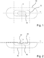
- Figure 1 shows in detail, purely qualitative, an overlay of three high beam distributions 10, 12, 14 as they appear on a screen standing vertically in front of a headlight, together with the indication of a vertical direction V and the indication of a horizontal direction H.
- the widest of the three light distributions is also referred to below as extra wide spread high beam distribution 10.
- the next narrower high beam distribution is also referred to below as wide spread high beam distribution 12, and the narrowest of the three light distributions is also referred to below as hot spot light distribution 14.
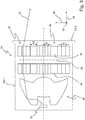
- Figure 2 shows corresponding low beam distributions 16, 18, 20 with a congruent light / dark boundary 22 for all three low beam distributions 16, 18, 20 in the overlapping area.
- the widest of the three light distributions is also referred to below as extra wide spread low beam distribution 16.
- the next narrower light distribution is also referred to below as the wide spread low beam distribution 18, and the narrowest of the three light distributions is also referred to below as the hot spot low beam distribution 20.
- FIG 3 shows an embodiment of a motor vehicle headlight 24 according to the invention, in a lateral section.
- the sectional plane is spanned by the direction 26 of a longitudinal axis and the direction 28 of a vertical axis of the motor vehicle.
- the direction 30 of a transverse axis of the motor vehicle is perpendicular to the cutting plane.
- the headlight 24 has a light module 30, which has a light source 32, primary optics 36 that collect and parallelize light 34 from the light source 32, and a plurality of microprojectors 38.
- the light source 32 is a semiconductor light source, preferably a light-emitting diode or laser diode, or an array having a plurality of such diodes.
- the light module is arranged in a housing 24.1 of the headlight 24. A light exit opening of the headlight is covered by a transparent cover plate 24.2.
- the microprojectors 38 differ in part in their parallel to the direction of the vertical axis 28 in Figure 1 lying height.
- First microprojectors have a small height h1. These micro projectors are used to generate a hot spot light distribution.
- Second microprojectors have an average height h2. These micro projectors are used to generate a wide spread light distribution.
- Third microprojectors have a large height h3. These micro projectors are used to generate an extra wide spread light distribution.
- the terms small, medium and large are used here to qualitatively differentiate between the three microprojectors of different heights and are therefore not to be understood as being quantitatively limited to certain values.
- Each microprojector 38 has an input lens 40, one Aperture 42 (applies to low beam microprojectors) and an output lens 44.
- the front sides of the coupling and decoupling surfaces have the same distances from the diaphragm surface, both for hot spot and for wide spread and extra wide spread microprojectors. This means that the magnification factors of these microprojectors are also the same.
- the microprojectors thus generate images of unequal size in the far field. A brightness distribution in the far field results from the superimposition of images of different sizes. If the distances were not the same but different, this would require scaling of the diaphragms. Larger distances increase the focal length and reduce the opening angle of the exit light cone.
- light beam cross-sections of different sizes are generated only by different sizes of the entrance pupils of the microprojectors.
- the diaphragms 42 only serve to form the light-dark boundary.
- Narrow light distributions in the far field are generated by narrow entrance pupils (e.g. hot spot).
- High intensities are generated by superimposing many narrow light distributions, i.e. by superimposing the contributions from a comparatively large number of microprojectors.
- Wide light distributions in the far field are generated by wide entrance pupils (e.g. wide spread, extra wide spread). Low intensities are generated by superimposing the contributions from fewer microprojectors.
- Figure 4 shows the microprojectors each in a perspective representation on the same scale and in a conceptual overlay for a size comparison. It shows Figure 4a a first microprojector 46, Figure 4b a second microprojector 48, Figure 4c a third microprojector 50, and Figure 4d shows the intellectual Superposition of the three microprojectors 46, 48, 50. Each of the Figures 4a to 4d also shows an optical axis 52. When the headlight is used as intended, the optical axis 52 has the direction of the longitudinal axis of the motor vehicle.
- Each of the microprojectors has an input lens 46.1, 48.1, 50.1, an output lens 46.2, 48.2, 50.2 and a diaphragm 46.3, 48.3, 50.3 arranged between the input lens and the output lens.
- the input lenses and the diaphragms each have a width b extending parallel to a horizontal direction and a height h extending parallel to the vertical direction.
- Each output lens of a microprojector preferably has the same width b and the same height h as the associated input lens of the microprojector.
- the primary optics and the input lens, diaphragm and output lens each of a microprojector are arranged such that light of the light source emerging from the primary optics illuminates the input lens and light from the light source emerging from the input lens illuminates the output lens.
- the microprojectors are characterized by the fact that their widths are different and their heights are different.
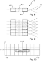
- FIG. 4 shows a horizontal section of a single first (hot spot) microprojector 46 and FIG Figure 6 shows a horizontal section of a line of first microprojectors 46 together with idealized light beam courses.
- Figure 7 shows ISO lines of the same intensity in a hot spot low beam distribution generated by several first microprojectors. This draws is characterized by a sharp cut-off line at the top and a gentle run-out on the sides with a gradual decrease in brightness. Examples of light intensities in candela (cd) are given on the right abscissa.
- the local shifts in the overlap to form a common light distribution curve on the street are in the order of magnitude of the individual microprojector dimensions. These are in the millimeter range and are significantly smaller than the local cross-sectional area of their light cones on the street. Such a small local shift has almost no influence on the sharpness of the light-dark boundary and at most contributes to better color mixing or homogenization of the common light distribution curve.
- FIG. 8 shows a horizontal section of a single second (wide spread) microprojector 48 and
- FIG Figure 9 shows a horizontal section of a line of second microprojectors together with idealized light beam courses.
- Figure 10 shows ISO lines of the same intensity in a wide spread low beam distribution generated by several second microprojectors. This is characterized by a sharp cut-off line at the top and a gentle run-out on the sides with a gradual decrease in brightness. Examples of light intensities in candela (cd) are given on the right abscissa.
- the larger cross-sectional profile (entrance pupil) is responsible for covering a larger coupling-out angle.
- the number of wide spread microprojectors is smaller compared to the number of hot spot microprojectors with a comparable installation space. Therefore the diaphragm projections on the street are identical in terms of the course of the light-dark borders, but overall wider in their horizontal and vertical dimensions and consequently paler (lower light intensity).
- the light distribution generated by the wide spread microprojectors therefore has a quantitatively comparatively weaker maximum at the same point at which the maximum of the hot spot light distribution is also located. There is also a gentle spout on the sides.
- FIG. 11 shows a horizontal section of a single third (extra wide spread) microprojector 50 and Figure 12 shows a horizontal section of a line of third microprojectors 50 together with idealized light beam courses.
- Figure 13 shows ISO lines of the same intensity in an extra wide spread low beam distribution generated by several third microprojectors. This is characterized by an upwardly sharp light-dark border and a gentle run-out on the sides with a gradual decrease in brightness.
- abscissa are examples of light intensities in candela (cd).
- the light-dark boundaries of the hot spot, wide spread and extra wide spread light distributions have an identical course in the area of their overlap.
- the respective diaphragm edges are projected, possibly also enlarged differently, as images of the same size, even if light distributions of different widths and light-dark boundaries are generated by different narrow beam paths.
- the diaphragm edges are also designed (scaled) to the same scale, or all microprojectors have identical imaging scales.
- the optical components of the microprojectors have the following widths B, heights H and depths T and other dimensions: Hot spot lenses: 2.3mm x 1.4mm x 5.0mm (W x H x D) Wide spread lenses: 3.6mm x 2.1mm x 5.0mm (W x H x D) extra wide spread Lenses: 5.0mm x 3.6mm x 5.0mm (W x H x D) Lens distance: 4.0mm Panel thickness: 0.1mm, in the middle between
- the optical axes of the imaging microprojector lenses determine the optical axes of the respective microprojectors and are arranged parallel or almost parallel to one another.
- the narrower the individual micro-projectors the smaller the opening angles of individual micro-bundles despite their short focal lengths. This is especially true for the hot spot microprojectors. This means that there is less color dispersion at the edges of the lens.
- the focal points of the input lens of the microprojectors are located downstream of the aperture of the respective microprojector.
- the light exit surfaces of the output lenses of the microprojectors are preferably equally curved.
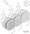
- Figure 14a shows a first light module 54, which only has first microprojectors.
- Figure 14b shows a second light module 56 which has only second microprojectors and
- Figure 14c shows a third light module 58 which has only third microprojectors.
- the first light module 54 only has first microprojectors whose first widths are the same and whose first heights are the same.
- the second light module 56 has only second microprojectors whose second widths are the same and whose second heights are the same.
- the third light module 58 has only third microprojectors whose third widths are the same and whose third heights are the same.
- the heights are each parallel to the vertical axis 28.
- the widths are each parallel to the transverse axis 30.
- the first widths of the first microprojectors are different from the second widths of the second microprojectors and the third widths of the third microprojectors.
- the first heights of the first microprojectors differ from the second heights of the second microprojectors and the third heights of the third microprojectors.
- Each module consists of a collimating primary optics, an input lens array, an aperture array and an output lens array.
- Each module type has, for example, the dimensions of 25mm x 25mm x 30mm (height H x width W x depth D). It is characteristic that the micro projector cross-sections for hot spot, wide spread and extra wide spread are of different sizes. The higher light intensity in the hot spot is with Generated micro projectors whose cross sections are smaller than the cross sections of the wide spread micro projectors. The cross-sections of the wide spread micro-projectors are smaller than the cross-sections of the extra wide spread micro-projectors.
- the imaging quality is highest near the common optical axis 52 up to approximately +/- 10 ° to the side thereof. From around +/- 10 °, the image quality inevitably decreases due to the simple structure of the projectors.
- the good image quality results in homogeneous, seamless overlaps of the light distributions when the individual modules are adjusted accordingly, so that the overall light distribution resulting from the superimposition can be perceived as an overall homogeneous and color-compensated light distribution. There are no sudden differences in brightness between the individual partial light distributions.
- Figure 14d shows an ensemble 60 of such a first light module 54, such a second light module 56 and such a third light module 58.
- the three light modules are preferably used together in a headlight, for example to form a low beam distribution, which consists of a hot spot component, a wide spread portion and an extra wide spread portion.
- the motor vehicle headlight is characterized in that it has microprojectors whose widths are different and whose heights are different.
- a superposition of several partial light distributions, which are generated with microprojectors of different cross-sections, can also be done with a single type of light module be realized.
- the Figures 15a and 15b show a light module 62 that includes microprojectors that are different in width and different in height.
- the Figure 15a an exploded view along the optical axis 52, in which the light source 32, primary optics 36, input lens array 64, diaphragm array 66 and output lens array 68 can be clearly seen separated from one another.
- Figure 15b shows the light module 62 in a functional assembly state.
- Figure 15b shows particularly clearly that microprojectors 46, 48, 50 of different cross-sections are present.
- the Figures 15a , 15th show an example of how different microprojector types 46, 48, 50 distributed in rows or columns or according to another pattern are combined in a hybrid microprojector array, the term “hybrid” in this application denoting the use of microprojectors with different Describes cross-sections in connection with a common collimating primary optics 36 and light source 32.
- hybrid light modules 62 By using hybrid light modules 62 it is possible to put together various combinations of hot spot, wide spread and extra wide spread microprojectors.
- the various components in the overall light distribution can thus be emphasized to different degrees so that, for example, an overall light distribution with a pronounced maximum or with a larger or smaller horizontal and / or vertical opening angle can be generated. Different row or column combinations, even mixed rows are conceivable.
- the microprojectors can be placed anywhere to each other (preferably parallel or almost parallel) so that the full cross section of the light bundle collimated by the primary optics is used.
- a plurality of such hybrid light modules are used in a headlight, with each hybrid light module generating a complete, scaled light distribution (scaled: different sizes, but with the same proportions). It is thus possible to generate the required light distribution with, for example, two to three identical hybrid light modules via a suitable energization of the light sources.
- microprojectors of different sizes are combined in a single microprojector module 62, so that hot spot, wide spread and extra wide spread microprojector arrays are assigned to a light source 32 or a collimator 36.
- the overall light distribution of such a module 62 thus covers the entire prescribed angular range.
- the overall light distribution is defined by the "mixing ratios" of the microprojector cross-section types and can be dimmed finely or continuously by energizing the light source. Their contrast ratios are ideally retained.
- the collimating primary optics 36 have a residual divergence in practice.
- the light from the light source emanating from the primary optics is therefore not completely parallel, but rather has an opening angle of a few degrees.
- the cross section of the collimated or bundled Luminous flux has locally different luminous intensities. This means that, depending on the position at which a microprojector is located in the collimator light beam, it projects the geometrically identical light-dark boundary image onto the street, but illuminates it differently. Each image may have a different focus of light or is even only partially illuminated.
- the total light distribution is the sum of the individual images. It is important that the color effects caused by the dispersion cancel each other out in their entirety due to the superimposition of the individual images.
- the proposed hybrid light module can lead to a simplification and to higher quantities. Only one type of module would be required instead of having to develop different modules for hot spot, wide spread and extra wide spread partial light distributions and produce them in smaller numbers.
- the dimensions of the active optics of a hybrid light module are, for example, approx. 25mm x 25mm (height x width) and an overall depth of approx. 30mm. Assuming three modules were required to generate a low beam distribution, this would result, for example, in 25mm x 75mm x 30mm (height x width x depth). Compared to the dimensions of a conventional projection module of approx. 75mm x 75mm x 120mm (height x width x depth), the result is a reduction in volume on the order of a factor of 1/12.
- the invention enables impressive savings in installation space (reduction of up to approx. 1/100 is conceivable) and produces an extremely homogeneous overall light distribution with a sharp cut-off line.
- the modularity and the very good manufacturability and robust functionality result in the advantage of low expected production costs.
Landscapes
- Engineering & Computer Science (AREA)
- General Engineering & Computer Science (AREA)
- Physics & Mathematics (AREA)
- Optics & Photonics (AREA)
- General Physics & Mathematics (AREA)
- Microelectronics & Electronic Packaging (AREA)
- Non-Portable Lighting Devices Or Systems Thereof (AREA)
- Lighting Device Outwards From Vehicle And Optical Signal (AREA)
Claims (10)
- Phare de véhicule automobile (24) avec un module lumineux (30) qui comporte une source lumineuse (32), une optique primaire collectant de la lumière (34) de la source lumineuse (32) et une pluralité de microprojecteurs (38) dont chacun comporte respectivement une lentille d'entrée (40), une lentille de sortie (44) et un diaphragme (42) disposé entre la lentille d'entrée et la lentille de sortie, la lentille d'entrée (40), le diaphragme (42) et la lentille de sortie (44) présentant, lors d'une utilisation conforme du phare de véhicule automobile (24), une largeur s'étendant parallèlement à une direction horizontale (30) et une hauteur s'étendant parallèlement à une direction verticale (28), l'optique primaire (36), la lentille d'entrée (40), le diaphragme (42) et la lentille de sortie (44) d'un microprojecteur (38) respectif étant disposés de façon que de la lumière de la source lumineuse (32) sortant de l'optique primaire (36) éclaire la lentille d'entrée (40) et que de la lumière de la source lumineuse (32) sortant de la lentille d'entrée (40) éclaire la lentille de sortie (44), caractérisé en ce que le phare de véhicule automobile (24) comprend des microprojecteurs (46, 48, 50) dont les largeurs sont différentes et dont le hauteurs (h1, h2, h3) sont différentes.
- Phare de véhicule automobile (24) selon la revendication 1, caractérisé en ce que des points focaux de la lentille d'entrée d'au moins un des microprojecteurs sont situés, dans une direction de propagation de la lumière de la source lumineuse sortant de la lentille d'entrée, derrière le diaphragme dudit au moins un microprojecteur.
- Phare de véhicule automobile (24) selon l'une des revendications précédentes, caractérisé en ce que les surfaces de sortie de lumière des lentilles de sortie d'au moins deux des microprojecteurs sont courbées de la même mesure.
- Phare de véhicule automobile (24) selon l'une des revendications précédentes, caractérisé en ce que le phare de véhicule automobile (24) comprend des premiers microprojecteurs (46) présentant une première largeur et une première hauteur, des deuxièmes microprojecteurs (48) présentant une deuxième largeur et une deuxième hauteur et des troisièmes microprojecteurs (50) présentant une troisième largeur et une troisième hauteur.
- Phare de véhicule automobile (24) selon la revendication 4, caractérisé en ce qu'il comporte plusieurs modules lumineux, chaque module lumineux comportant une source lumineuse (32), une optique primaire (36) collectant de la lumière (34) de la source lumineuse (32) et une pluralité de microprojecteurs (38) dont chacun comporte respectivement une lentille d'entrée (40), une lentille de sortie (44) et un diaphragme (42) disposé entre la lentille d'entrée et la lentille de sortie, la lentille d'entrée (40), le diaphragme (42) et la lentille de sortie (44) comportant, lors d'une utilisation conforme du phare de véhicule automobile (24), une largeur (b) s'étendant parallèlement à une direction (30) horizontale, une hauteur (h) s'étendant parallèlement à une direction (28) verticale, l'optique primaire (36), la lentille d'entrée (40), le diaphragme (42) et la lentille de sortie (44) d'un microprojecteur (38) respectif étant positionnés de manière telle que de la lumière de la source de lumière (32) sortant de l'optique primaire (36) éclaire la lentille d'entrée (40) et que de la lumière de la source lumineuse (32) sortant de la lentille d'entrée (40) éclaire la lentille de sortie (44).
- Phare de véhicule automobile (24) selon la revendication 5, caractérisé en ce qu'un premier module lumineux (54) desdits plusieurs modules lumineux ne comprend que des premiers microprojecteurs (46), dont les largueurs sont égales et dont les hauteurs sont égales et en ce qu'un deuxième module lumineux (56) desdits plusieurs modules lumineux ne comprend que des deuxièmes microprojecteurs (48) dont les largueurs sont égales et dont les hauteurs sont égales, les largueurs des premiers microprojecteurs (46) se distinguant des largueurs des deuxièmes microjecteurs (50) et les hauteurs des premiers microprojecteurs (46) se distinguant des hauteurs des deuxièmes microprojecteurs (48).
- Phare de véhicule automobile (24) selon une des revendications précédentes, caractérisé en ce qu'un module lumineux (62) comprend des microprojecteurs (46, 48, 50) dont les largueurs sont différentes et dont les hauteurs sont différentes.
- Phare de véhicule automobile (24) selon la revendication 7, caractérisé en ce qu'une somme des largueurs de microprojecteurs d'un module lumineux disposés les uns à côté des autres est inférieure à 30 mm et en ce qu'une somme des hauteurs de microprojecteurs d'un module lumineux disposés les uns au-dessus des autres est inférieure à 30 mm.
- Phare de véhicule automobile (24) selon l'une des revendications précédentes, caractérisé en ce que les largueurs des microprojecteurs sont inférieures à 6 mm, les hauteurs des microprojecteurs sont inférieures à 4 mm et que la profondeur d'une lentille respective des microprojecteurs est inférieure à 6mm.
- Phare de véhicule automobile (24) selon l'une des revendications précédentes, caractérisé en ce que le phare de véhicule automobile comporte plusieurs modules lumineux, chaque module lumineux comportant une source lumineuse (32), une optique primaire (36) collectant de la lumière (34) de la source lumineuse (32) et une pluralité de microprojecteurs (38) dont chacun comporte respectivement une lentille d'entrée (40), une lentille de sortie (44) et un diaphragme (42) disposé entre la lentille d'entrée et la lentille de sortie, la lentille d'entrée (40), le diaphragme (42) et la lentille de sortie (44) comportant, lors d'une utilisation conforme du phare de véhicule automobile (24), une largeur (b) s'étendant parallèlement à une direction (30) horizontale, une hauteur (h) s'étendant parallèlement à une direction (28) verticale, l'optique primaire (36), la lentille d'entrée (40), le diaphragme (42) et la lentille de sortie (44) d'un microprojecteur (38) respectif étant positionnés de manière telle que de la lumière de la source de lumière (32) sortant de l'optique primaire (36) éclaire la lentille d'entrée (40) et que de la lumière de la source lumineuse (32) sortant de la lentille d'entrée (40) éclaire la lentille de sortie (44), caractérisé en ce que les optiques primaires (36) collectant de la lumière, d'au moins deux des modules lumineux focalisent différemment la lumière entrant dans elles.
Applications Claiming Priority (1)
| Application Number | Priority Date | Filing Date | Title |
|---|---|---|---|
| DE102017110886.6A DE102017110886A1 (de) | 2017-05-18 | 2017-05-18 | Kraftfahrzeugscheinwerfer mit einem Mikroprojektoren aufweisenden Lichtmodul |
Publications (2)
| Publication Number | Publication Date |
|---|---|
| EP3404313A1 EP3404313A1 (fr) | 2018-11-21 |
| EP3404313B1 true EP3404313B1 (fr) | 2020-12-02 |
Family
ID=61911497
Family Applications (1)
| Application Number | Title | Priority Date | Filing Date |
|---|---|---|---|
| EP18166107.5A Active EP3404313B1 (fr) | 2017-05-18 | 2018-04-06 | Phare de véhicule automobile pourvu de module lumineux comportant des microprojecteurs |
Country Status (4)
| Country | Link |
|---|---|
| US (1) | US10295137B2 (fr) |
| EP (1) | EP3404313B1 (fr) |
| CN (1) | CN108954213A (fr) |
| DE (1) | DE102017110886A1 (fr) |
Families Citing this family (23)
| Publication number | Priority date | Publication date | Assignee | Title |
|---|---|---|---|---|
| FR3070925B1 (fr) * | 2017-09-12 | 2020-09-04 | Valeo Vision | Module lumineux pour vehicule automobile, et dispositif d'eclairage et/ou de signalisation muni d'un tel module |
| US10551029B2 (en) * | 2018-02-06 | 2020-02-04 | HELLA GmbH & Co. KGaA | Lighting device with homogeneous light distribution |
| DE102018107214A1 (de) * | 2018-03-27 | 2019-10-02 | HELLA GmbH & Co. KGaA | Beleuchtungsvorrichtung für Fahrzeuge |
| EP3608586A1 (fr) * | 2018-08-07 | 2020-02-12 | ZKW Group GmbH | Dispositif de projection, module lumineux et phares de véhicule automobile de micro-optiques |
| US10634307B2 (en) * | 2018-09-06 | 2020-04-28 | Sl Corporation | Lamp for vehicle |
| DE102018217215A1 (de) | 2018-10-09 | 2020-04-09 | Fraunhofer-Gesellschaft zur Förderung der angewandten Forschung e.V. | Abblendlichtscheinwerfer |
| KR20200080838A (ko) * | 2018-12-27 | 2020-07-07 | 에스엘 주식회사 | 차량용 램프 |
| JP7311746B2 (ja) * | 2019-01-31 | 2023-07-20 | 日亜化学工業株式会社 | レンズアレイ及び照明光学装置 |
| EP3770491A1 (fr) * | 2019-07-24 | 2021-01-27 | Regent Beleuchtungskörper AG | Dispositif d'éclairage |
| JPWO2021060201A1 (fr) * | 2019-09-24 | 2021-04-01 | ||
| WO2021060200A1 (fr) * | 2019-09-24 | 2021-04-01 | 株式会社小糸製作所 | Réseau de microlentilles de véhicule et lampe de véhicule dans laquelle il est utilisé |
| KR20210053024A (ko) * | 2019-11-01 | 2021-05-11 | 에스엘 주식회사 | 차량용 램프 |
| DE102020102226A1 (de) * | 2020-01-30 | 2021-08-05 | HELLA GmbH & Co. KGaA | Beleuchtungsvorrichtung für ein Fahrzeug, insbesondere Scheinwerfer |
| DE102020102568B4 (de) | 2020-02-03 | 2022-12-08 | HELLA GmbH & Co. KGaA | Beleuchtungsvorrichtung für ein Kraftfahrzeug, insbesondere Scheinwerfer, mit einer Aufhellvorrichtung zur Vergrößerung der ausgeleuchteten Fläche der Austrittsfläche einer Projektionsoptik |
| DE102020107926A1 (de) | 2020-03-23 | 2021-10-07 | Marelli Automotive Lighting Reutlingen (Germany) GmbH | Mikrolinsenprojektionsmodul mit an Ausleuchtdivergenz angepasster Bklende |
| DE102020112316A1 (de) | 2020-05-06 | 2021-11-11 | Suss Microoptics Sa | Projektionssystem und Fahrzeug mit Projektionssystem |
| KR102390805B1 (ko) * | 2020-06-09 | 2022-04-26 | 현대모비스 주식회사 | 자동차용 램프 및 그 램프를 포함하는 자동차 |
| KR20220021309A (ko) * | 2020-08-13 | 2022-02-22 | 현대모비스 주식회사 | 자동차용 램프 및 그 램프를 포함하는 자동차 |
| KR20220021168A (ko) * | 2020-08-13 | 2022-02-22 | 에스엘 주식회사 | 차량용 램프 |
| KR20220026310A (ko) * | 2020-08-25 | 2022-03-04 | 에스엘 주식회사 | 차량용 램프 |
| TWI726829B (zh) * | 2020-11-17 | 2021-05-01 | 坦德科技股份有限公司 | 導光柱結構 |
| DE102021103514B4 (de) * | 2021-02-15 | 2022-10-27 | Volkswagen Aktiengesellschaft | Verfahren zur konfiguration eines scheinwerfersystems für ein fahrzeug |
| US11703202B2 (en) | 2021-08-10 | 2023-07-18 | ams OSRAM Automotive Lighting Systems USA Inc. | Image projection lighting assembly |
Citations (1)
| Publication number | Priority date | Publication date | Assignee | Title |
|---|---|---|---|---|
| US20120106164A1 (en) * | 2009-04-03 | 2012-05-03 | Fraunhofer-Gsellschaft zur Foerderung der angewandten Forschung e.V. | Beam shaper |
Family Cites Families (17)
| Publication number | Priority date | Publication date | Assignee | Title |
|---|---|---|---|---|
| IT1279129B1 (it) * | 1995-04-19 | 1997-12-04 | Carello Spa | Dispositivo di illuminazione, in particolare proiettore per veicoli. |
| IT1305161B1 (it) | 1998-11-05 | 2001-04-10 | Fiat Ricerche | Dispositivo di illuminazione adattativo, a doppio proiettore, perautoveicoli, con matrici di microlenti. |
| DE10039086A1 (de) * | 2000-08-10 | 2002-02-21 | Daimler Chrysler Ag | Scheinwerfer mit einstellbarer Ablenkung des Scheinwerferlichts |
| JP4024628B2 (ja) * | 2002-09-03 | 2007-12-19 | 株式会社小糸製作所 | 車両用前照灯 |
| JP4138586B2 (ja) * | 2003-06-13 | 2008-08-27 | スタンレー電気株式会社 | 光源用ledランプおよびこれを用いた車両用前照灯 |
| JP4402425B2 (ja) * | 2003-10-24 | 2010-01-20 | スタンレー電気株式会社 | 車両前照灯 |
| EP2034235B1 (fr) * | 2007-09-04 | 2013-11-06 | Hella KGaA Hueck & Co. | Phare pour véhicules |
| JP2010140888A (ja) * | 2008-11-14 | 2010-06-24 | Seiko Epson Corp | 照明装置、プロジェクタ |
| JP5157883B2 (ja) * | 2008-12-25 | 2013-03-06 | 市光工業株式会社 | 車両用前照灯 |
| FR2948439B1 (fr) * | 2009-07-21 | 2011-08-05 | Valeo Vision | Module d'eclairage pour projecteur de vehicule automobile, et projecteur equipe d'au moins un tel module. |
| DE102009053581B3 (de) | 2009-10-05 | 2011-03-03 | Automotive Lighting Reutlingen Gmbh | Lichtmodul für eine Beleuchtungseinrichtung eines Kraftfahrzeugs |
| JP5445049B2 (ja) * | 2009-11-13 | 2014-03-19 | スタンレー電気株式会社 | 車両用灯具 |
| CN201992529U (zh) * | 2010-05-28 | 2011-09-28 | 天津方合科技发展有限公司 | 近光带有明暗截止线的汽车前照灯led光源 |
| AT510931B1 (de) * | 2010-12-22 | 2013-09-15 | Zizala Lichtsysteme Gmbh | Fahrzeugscheinwerfer mit led-lichtmodul |
| WO2013183240A1 (fr) * | 2012-06-05 | 2013-12-12 | 株式会社小糸製作所 | Ampoule d'éclairage pour véhicule |
| AT514967B1 (de) | 2013-10-25 | 2015-08-15 | Zizala Lichtsysteme Gmbh | Mikroprojektions-Lichtmodul für einen Kraftfahrzeugscheinwerfer |
| DE102015107644A1 (de) * | 2015-05-15 | 2016-11-17 | Hella Kgaa Hueck & Co. | Signalleuchte für Fahrzeuge |
-
2017
- 2017-05-18 DE DE102017110886.6A patent/DE102017110886A1/de not_active Withdrawn
-
2018
- 2018-04-06 EP EP18166107.5A patent/EP3404313B1/fr active Active
- 2018-05-02 US US15/969,221 patent/US10295137B2/en active Active
- 2018-05-16 CN CN201810469319.7A patent/CN108954213A/zh active Pending
Patent Citations (1)
| Publication number | Priority date | Publication date | Assignee | Title |
|---|---|---|---|---|
| US20120106164A1 (en) * | 2009-04-03 | 2012-05-03 | Fraunhofer-Gsellschaft zur Foerderung der angewandten Forschung e.V. | Beam shaper |
Also Published As
| Publication number | Publication date |
|---|---|
| US10295137B2 (en) | 2019-05-21 |
| US20180335191A1 (en) | 2018-11-22 |
| EP3404313A1 (fr) | 2018-11-21 |
| CN108954213A (zh) | 2018-12-07 |
| DE102017110886A1 (de) | 2018-11-22 |
Similar Documents
| Publication | Publication Date | Title |
|---|---|---|
| EP3404313B1 (fr) | Phare de véhicule automobile pourvu de module lumineux comportant des microprojecteurs | |
| AT517887B1 (de) | Mikroprojektions-Lichtmodul für Fahrzeugscheinwerfer | |
| EP3365594B1 (fr) | Module lumineux à microprojection pour un projecteur de véhicule à moteur servant à produire des répartitions de lumière sans aberration | |
| EP3282182B1 (fr) | Phare de véhicule automobile de faible épaisseur | |
| EP3864341B1 (fr) | Phare à feu de croisement | |
| AT512468B1 (de) | Beleuchtungsmodul für ein kraftfahrzeug | |
| EP2799762B1 (fr) | Module d'éclairage de phare de véhicule automobile | |
| EP3864342B1 (fr) | Projecteur de feu de route | |
| EP3042118B1 (fr) | Dispositif d'éclairage d'un phare de véhicule automobile avec une structure optique | |
| EP2578929B1 (fr) | Agencement d'éléments de rétroprojection sur une lentille de projection d'un phare de véhicule automobile | |
| EP3524873B1 (fr) | Module lumineux de projection efficace comportant des microprojecteurs pour un phare de véhicule automobile | |
| EP3833904B1 (fr) | Dispositif de projection, module lumineux et phares de véhicule automobile de micro-optiques | |
| DE102017112971A1 (de) | Kraftfahrzeugscheinwerfer mit wenigstens zwei Ausgangsteillinsen aufweisenden Mikroprojektionsmodulen | |
| EP3372890B1 (fr) | Module de phare de véhicule automobile | |
| EP3699486B1 (fr) | Phare pourvu d'une pluralité de sources lumineuses à semi-conducteurs et d'un champ optique primaire en une pièce | |
| EP3301350A1 (fr) | Module d'éclairage pour phare de véhicule automobile | |
| EP3671304B1 (fr) | Procédé de construction d'un élément optique pour un phare de véhicule automobile | |
| EP3765781A1 (fr) | Module de lumière pour phare de véhicule automobile | |
| EP3657066B1 (fr) | Unité d'éclairage pour un phare de véhicule automobile destinée à générer une répartition lumineuse à coupure | |
| DE102018207516B3 (de) | Head-Up-Display mit einer von mehreren verteilt angeordneten Lichtquellen beleuchteten Anzeige | |
| EP3719391B1 (fr) | Module de feu de route partiel pour un phare de véhicule automobile | |
| WO2024062108A1 (fr) | Projecteur de croisement et procédé de fabrication | |
| DE102022210090A1 (de) | Optischer strahlformer und maskenloser zeichenprojektor | |
| DE102019125971A1 (de) | Kraftfahrzeugscheinwerfer mit einem Lichtmodul und breit ausgeleuchteter Lichtaustrittslinse |
Legal Events
| Date | Code | Title | Description |
|---|---|---|---|
| PUAI | Public reference made under article 153(3) epc to a published international application that has entered the european phase |
Free format text: ORIGINAL CODE: 0009012 |
|
| STAA | Information on the status of an ep patent application or granted ep patent |
Free format text: STATUS: THE APPLICATION HAS BEEN PUBLISHED |
|
| AK | Designated contracting states |
Kind code of ref document: A1 Designated state(s): AL AT BE BG CH CY CZ DE DK EE ES FI FR GB GR HR HU IE IS IT LI LT LU LV MC MK MT NL NO PL PT RO RS SE SI SK SM TR |
|
| AX | Request for extension of the european patent |
Extension state: BA ME |
|
| STAA | Information on the status of an ep patent application or granted ep patent |
Free format text: STATUS: REQUEST FOR EXAMINATION WAS MADE |
|
| 17P | Request for examination filed |
Effective date: 20190521 |
|
| RBV | Designated contracting states (corrected) |
Designated state(s): AL AT BE BG CH CY CZ DE DK EE ES FI FR GB GR HR HU IE IS IT LI LT LU LV MC MK MT NL NO PL PT RO RS SE SI SK SM TR |
|
| RIC1 | Information provided on ipc code assigned before grant |
Ipc: F21S 41/143 20180101AFI20200504BHEP Ipc: F21S 41/265 20180101ALI20200504BHEP Ipc: F21Y 115/10 20160101ALN20200504BHEP Ipc: F21S 41/43 20180101ALI20200504BHEP Ipc: F21V 5/00 20180101ALI20200504BHEP |
|
| GRAP | Despatch of communication of intention to grant a patent |
Free format text: ORIGINAL CODE: EPIDOSNIGR1 |
|
| STAA | Information on the status of an ep patent application or granted ep patent |
Free format text: STATUS: GRANT OF PATENT IS INTENDED |
|
| RIC1 | Information provided on ipc code assigned before grant |
Ipc: F21V 5/00 20180101ALI20200518BHEP Ipc: F21S 41/265 20180101ALI20200518BHEP Ipc: F21Y 115/10 20160101ALN20200518BHEP Ipc: F21S 41/143 20180101AFI20200518BHEP Ipc: F21S 41/43 20180101ALI20200518BHEP |
|
| INTG | Intention to grant announced |
Effective date: 20200623 |
|
| GRAS | Grant fee paid |
Free format text: ORIGINAL CODE: EPIDOSNIGR3 |
|
| GRAA | (expected) grant |
Free format text: ORIGINAL CODE: 0009210 |
|
| STAA | Information on the status of an ep patent application or granted ep patent |
Free format text: STATUS: THE PATENT HAS BEEN GRANTED |
|
| AK | Designated contracting states |
Kind code of ref document: B1 Designated state(s): AL AT BE BG CH CY CZ DE DK EE ES FI FR GB GR HR HU IE IS IT LI LT LU LV MC MK MT NL NO PL PT RO RS SE SI SK SM TR |
|
| REG | Reference to a national code |
Ref country code: GB Ref legal event code: FG4D Free format text: NOT ENGLISH |
|
| REG | Reference to a national code |
Ref country code: AT Ref legal event code: REF Ref document number: 1341319 Country of ref document: AT Kind code of ref document: T Effective date: 20201215 Ref country code: CH Ref legal event code: EP |
|
| REG | Reference to a national code |
Ref country code: DE Ref legal event code: R096 Ref document number: 502018003150 Country of ref document: DE |
|
| REG | Reference to a national code |
Ref country code: IE Ref legal event code: FG4D Free format text: LANGUAGE OF EP DOCUMENT: GERMAN |
|
| PG25 | Lapsed in a contracting state [announced via postgrant information from national office to epo] |
Ref country code: RS Free format text: LAPSE BECAUSE OF FAILURE TO SUBMIT A TRANSLATION OF THE DESCRIPTION OR TO PAY THE FEE WITHIN THE PRESCRIBED TIME-LIMIT Effective date: 20201202 Ref country code: FI Free format text: LAPSE BECAUSE OF FAILURE TO SUBMIT A TRANSLATION OF THE DESCRIPTION OR TO PAY THE FEE WITHIN THE PRESCRIBED TIME-LIMIT Effective date: 20201202 Ref country code: NO Free format text: LAPSE BECAUSE OF FAILURE TO SUBMIT A TRANSLATION OF THE DESCRIPTION OR TO PAY THE FEE WITHIN THE PRESCRIBED TIME-LIMIT Effective date: 20210302 Ref country code: GR Free format text: LAPSE BECAUSE OF FAILURE TO SUBMIT A TRANSLATION OF THE DESCRIPTION OR TO PAY THE FEE WITHIN THE PRESCRIBED TIME-LIMIT Effective date: 20210303 |
|
| REG | Reference to a national code |
Ref country code: NL Ref legal event code: MP Effective date: 20201202 |
|
| PG25 | Lapsed in a contracting state [announced via postgrant information from national office to epo] |
Ref country code: BG Free format text: LAPSE BECAUSE OF FAILURE TO SUBMIT A TRANSLATION OF THE DESCRIPTION OR TO PAY THE FEE WITHIN THE PRESCRIBED TIME-LIMIT Effective date: 20210302 Ref country code: PL Free format text: LAPSE BECAUSE OF FAILURE TO SUBMIT A TRANSLATION OF THE DESCRIPTION OR TO PAY THE FEE WITHIN THE PRESCRIBED TIME-LIMIT Effective date: 20201202 Ref country code: LV Free format text: LAPSE BECAUSE OF FAILURE TO SUBMIT A TRANSLATION OF THE DESCRIPTION OR TO PAY THE FEE WITHIN THE PRESCRIBED TIME-LIMIT Effective date: 20201202 Ref country code: SE Free format text: LAPSE BECAUSE OF FAILURE TO SUBMIT A TRANSLATION OF THE DESCRIPTION OR TO PAY THE FEE WITHIN THE PRESCRIBED TIME-LIMIT Effective date: 20201202 |
|
| PG25 | Lapsed in a contracting state [announced via postgrant information from national office to epo] |
Ref country code: NL Free format text: LAPSE BECAUSE OF FAILURE TO SUBMIT A TRANSLATION OF THE DESCRIPTION OR TO PAY THE FEE WITHIN THE PRESCRIBED TIME-LIMIT Effective date: 20201202 Ref country code: HR Free format text: LAPSE BECAUSE OF FAILURE TO SUBMIT A TRANSLATION OF THE DESCRIPTION OR TO PAY THE FEE WITHIN THE PRESCRIBED TIME-LIMIT Effective date: 20201202 |
|
| REG | Reference to a national code |
Ref country code: LT Ref legal event code: MG9D |
|
| PG25 | Lapsed in a contracting state [announced via postgrant information from national office to epo] |
Ref country code: RO Free format text: LAPSE BECAUSE OF FAILURE TO SUBMIT A TRANSLATION OF THE DESCRIPTION OR TO PAY THE FEE WITHIN THE PRESCRIBED TIME-LIMIT Effective date: 20201202 Ref country code: PT Free format text: LAPSE BECAUSE OF FAILURE TO SUBMIT A TRANSLATION OF THE DESCRIPTION OR TO PAY THE FEE WITHIN THE PRESCRIBED TIME-LIMIT Effective date: 20210405 Ref country code: SK Free format text: LAPSE BECAUSE OF FAILURE TO SUBMIT A TRANSLATION OF THE DESCRIPTION OR TO PAY THE FEE WITHIN THE PRESCRIBED TIME-LIMIT Effective date: 20201202 Ref country code: LT Free format text: LAPSE BECAUSE OF FAILURE TO SUBMIT A TRANSLATION OF THE DESCRIPTION OR TO PAY THE FEE WITHIN THE PRESCRIBED TIME-LIMIT Effective date: 20201202 Ref country code: SM Free format text: LAPSE BECAUSE OF FAILURE TO SUBMIT A TRANSLATION OF THE DESCRIPTION OR TO PAY THE FEE WITHIN THE PRESCRIBED TIME-LIMIT Effective date: 20201202 Ref country code: EE Free format text: LAPSE BECAUSE OF FAILURE TO SUBMIT A TRANSLATION OF THE DESCRIPTION OR TO PAY THE FEE WITHIN THE PRESCRIBED TIME-LIMIT Effective date: 20201202 Ref country code: CZ Free format text: LAPSE BECAUSE OF FAILURE TO SUBMIT A TRANSLATION OF THE DESCRIPTION OR TO PAY THE FEE WITHIN THE PRESCRIBED TIME-LIMIT Effective date: 20201202 |
|
| REG | Reference to a national code |
Ref country code: DE Ref legal event code: R097 Ref document number: 502018003150 Country of ref document: DE |
|
| PG25 | Lapsed in a contracting state [announced via postgrant information from national office to epo] |
Ref country code: IS Free format text: LAPSE BECAUSE OF FAILURE TO SUBMIT A TRANSLATION OF THE DESCRIPTION OR TO PAY THE FEE WITHIN THE PRESCRIBED TIME-LIMIT Effective date: 20210402 |
|
| PLBE | No opposition filed within time limit |
Free format text: ORIGINAL CODE: 0009261 |
|
| STAA | Information on the status of an ep patent application or granted ep patent |
Free format text: STATUS: NO OPPOSITION FILED WITHIN TIME LIMIT |
|
| PG25 | Lapsed in a contracting state [announced via postgrant information from national office to epo] |
Ref country code: IT Free format text: LAPSE BECAUSE OF FAILURE TO SUBMIT A TRANSLATION OF THE DESCRIPTION OR TO PAY THE FEE WITHIN THE PRESCRIBED TIME-LIMIT Effective date: 20201202 Ref country code: AL Free format text: LAPSE BECAUSE OF FAILURE TO SUBMIT A TRANSLATION OF THE DESCRIPTION OR TO PAY THE FEE WITHIN THE PRESCRIBED TIME-LIMIT Effective date: 20201202 |
|
| 26N | No opposition filed |
Effective date: 20210903 |
|
| PG25 | Lapsed in a contracting state [announced via postgrant information from national office to epo] |
Ref country code: SI Free format text: LAPSE BECAUSE OF FAILURE TO SUBMIT A TRANSLATION OF THE DESCRIPTION OR TO PAY THE FEE WITHIN THE PRESCRIBED TIME-LIMIT Effective date: 20201202 Ref country code: DK Free format text: LAPSE BECAUSE OF FAILURE TO SUBMIT A TRANSLATION OF THE DESCRIPTION OR TO PAY THE FEE WITHIN THE PRESCRIBED TIME-LIMIT Effective date: 20201202 Ref country code: MC Free format text: LAPSE BECAUSE OF FAILURE TO SUBMIT A TRANSLATION OF THE DESCRIPTION OR TO PAY THE FEE WITHIN THE PRESCRIBED TIME-LIMIT Effective date: 20201202 |
|
| PG25 | Lapsed in a contracting state [announced via postgrant information from national office to epo] |
Ref country code: LU Free format text: LAPSE BECAUSE OF NON-PAYMENT OF DUE FEES Effective date: 20210406 |
|
| REG | Reference to a national code |
Ref country code: BE Ref legal event code: MM Effective date: 20210430 |
|
| PG25 | Lapsed in a contracting state [announced via postgrant information from national office to epo] |
Ref country code: LI Free format text: LAPSE BECAUSE OF NON-PAYMENT OF DUE FEES Effective date: 20210430 Ref country code: CH Free format text: LAPSE BECAUSE OF NON-PAYMENT OF DUE FEES Effective date: 20210430 Ref country code: ES Free format text: LAPSE BECAUSE OF FAILURE TO SUBMIT A TRANSLATION OF THE DESCRIPTION OR TO PAY THE FEE WITHIN THE PRESCRIBED TIME-LIMIT Effective date: 20201202 |
|
| PG25 | Lapsed in a contracting state [announced via postgrant information from national office to epo] |
Ref country code: IE Free format text: LAPSE BECAUSE OF NON-PAYMENT OF DUE FEES Effective date: 20210406 |
|
| PG25 | Lapsed in a contracting state [announced via postgrant information from national office to epo] |
Ref country code: IS Free format text: LAPSE BECAUSE OF FAILURE TO SUBMIT A TRANSLATION OF THE DESCRIPTION OR TO PAY THE FEE WITHIN THE PRESCRIBED TIME-LIMIT Effective date: 20210402 |
|
| PG25 | Lapsed in a contracting state [announced via postgrant information from national office to epo] |
Ref country code: BE Free format text: LAPSE BECAUSE OF NON-PAYMENT OF DUE FEES Effective date: 20210430 |
|
| GBPC | Gb: european patent ceased through non-payment of renewal fee |
Effective date: 20220406 |
|
| PG25 | Lapsed in a contracting state [announced via postgrant information from national office to epo] |
Ref country code: GB Free format text: LAPSE BECAUSE OF NON-PAYMENT OF DUE FEES Effective date: 20220406 |
|
| PGFP | Annual fee paid to national office [announced via postgrant information from national office to epo] |
Ref country code: FR Payment date: 20230321 Year of fee payment: 6 |
|
| P01 | Opt-out of the competence of the unified patent court (upc) registered |
Effective date: 20230508 |
|
| PG25 | Lapsed in a contracting state [announced via postgrant information from national office to epo] |
Ref country code: CY Free format text: LAPSE BECAUSE OF FAILURE TO SUBMIT A TRANSLATION OF THE DESCRIPTION OR TO PAY THE FEE WITHIN THE PRESCRIBED TIME-LIMIT Effective date: 20201202 |
|
| PG25 | Lapsed in a contracting state [announced via postgrant information from national office to epo] |
Ref country code: HU Free format text: LAPSE BECAUSE OF FAILURE TO SUBMIT A TRANSLATION OF THE DESCRIPTION OR TO PAY THE FEE WITHIN THE PRESCRIBED TIME-LIMIT; INVALID AB INITIO Effective date: 20180406 |
|
| PGFP | Annual fee paid to national office [announced via postgrant information from national office to epo] |
Ref country code: DE Payment date: 20230321 Year of fee payment: 6 |
|
| PGFP | Annual fee paid to national office [announced via postgrant information from national office to epo] |
Ref country code: AT Payment date: 20230322 Year of fee payment: 6 |
|
| PG25 | Lapsed in a contracting state [announced via postgrant information from national office to epo] |
Ref country code: MK Free format text: LAPSE BECAUSE OF FAILURE TO SUBMIT A TRANSLATION OF THE DESCRIPTION OR TO PAY THE FEE WITHIN THE PRESCRIBED TIME-LIMIT Effective date: 20201202 |