EP3404313A1 - Kraftfahrzeugscheinwerfer mit einem mikroprojektoren aufweisenden lichtmodul - Google Patents
Kraftfahrzeugscheinwerfer mit einem mikroprojektoren aufweisenden lichtmodul Download PDFInfo
- Publication number
- EP3404313A1 EP3404313A1 EP18166107.5A EP18166107A EP3404313A1 EP 3404313 A1 EP3404313 A1 EP 3404313A1 EP 18166107 A EP18166107 A EP 18166107A EP 3404313 A1 EP3404313 A1 EP 3404313A1
- Authority
- EP
- European Patent Office
- Prior art keywords
- light
- microprojectors
- motor vehicle
- lens
- vehicle headlight
- Prior art date
- Legal status (The legal status is an assumption and is not a legal conclusion. Google has not performed a legal analysis and makes no representation as to the accuracy of the status listed.)
- Granted
Links
Images





Classifications
-
- F—MECHANICAL ENGINEERING; LIGHTING; HEATING; WEAPONS; BLASTING
- F21—LIGHTING
- F21S—NON-PORTABLE LIGHTING DEVICES; SYSTEMS THEREOF; VEHICLE LIGHTING DEVICES SPECIALLY ADAPTED FOR VEHICLE EXTERIORS
- F21S41/00—Illuminating devices specially adapted for vehicle exteriors, e.g. headlamps
- F21S41/20—Illuminating devices specially adapted for vehicle exteriors, e.g. headlamps characterised by refractors, transparent cover plates, light guides or filters
- F21S41/25—Projection lenses
- F21S41/265—Composite lenses; Lenses with a patch-like shape
-
- F—MECHANICAL ENGINEERING; LIGHTING; HEATING; WEAPONS; BLASTING
- F21—LIGHTING
- F21S—NON-PORTABLE LIGHTING DEVICES; SYSTEMS THEREOF; VEHICLE LIGHTING DEVICES SPECIALLY ADAPTED FOR VEHICLE EXTERIORS
- F21S41/00—Illuminating devices specially adapted for vehicle exteriors, e.g. headlamps
- F21S41/10—Illuminating devices specially adapted for vehicle exteriors, e.g. headlamps characterised by the light source
- F21S41/14—Illuminating devices specially adapted for vehicle exteriors, e.g. headlamps characterised by the light source characterised by the type of light source
- F21S41/141—Light emitting diodes [LED]
-
- F—MECHANICAL ENGINEERING; LIGHTING; HEATING; WEAPONS; BLASTING
- F21—LIGHTING
- F21S—NON-PORTABLE LIGHTING DEVICES; SYSTEMS THEREOF; VEHICLE LIGHTING DEVICES SPECIALLY ADAPTED FOR VEHICLE EXTERIORS
- F21S41/00—Illuminating devices specially adapted for vehicle exteriors, e.g. headlamps
- F21S41/10—Illuminating devices specially adapted for vehicle exteriors, e.g. headlamps characterised by the light source
- F21S41/14—Illuminating devices specially adapted for vehicle exteriors, e.g. headlamps characterised by the light source characterised by the type of light source
- F21S41/141—Light emitting diodes [LED]
- F21S41/143—Light emitting diodes [LED] the main emission direction of the LED being parallel to the optical axis of the illuminating device
-
- F—MECHANICAL ENGINEERING; LIGHTING; HEATING; WEAPONS; BLASTING
- F21—LIGHTING
- F21S—NON-PORTABLE LIGHTING DEVICES; SYSTEMS THEREOF; VEHICLE LIGHTING DEVICES SPECIALLY ADAPTED FOR VEHICLE EXTERIORS
- F21S41/00—Illuminating devices specially adapted for vehicle exteriors, e.g. headlamps
- F21S41/10—Illuminating devices specially adapted for vehicle exteriors, e.g. headlamps characterised by the light source
- F21S41/14—Illuminating devices specially adapted for vehicle exteriors, e.g. headlamps characterised by the light source characterised by the type of light source
- F21S41/16—Laser light sources
-
- F—MECHANICAL ENGINEERING; LIGHTING; HEATING; WEAPONS; BLASTING
- F21—LIGHTING
- F21S—NON-PORTABLE LIGHTING DEVICES; SYSTEMS THEREOF; VEHICLE LIGHTING DEVICES SPECIALLY ADAPTED FOR VEHICLE EXTERIORS
- F21S41/00—Illuminating devices specially adapted for vehicle exteriors, e.g. headlamps
- F21S41/20—Illuminating devices specially adapted for vehicle exteriors, e.g. headlamps characterised by refractors, transparent cover plates, light guides or filters
- F21S41/25—Projection lenses
- F21S41/275—Lens surfaces, e.g. coatings or surface structures
-
- F—MECHANICAL ENGINEERING; LIGHTING; HEATING; WEAPONS; BLASTING
- F21—LIGHTING
- F21S—NON-PORTABLE LIGHTING DEVICES; SYSTEMS THEREOF; VEHICLE LIGHTING DEVICES SPECIALLY ADAPTED FOR VEHICLE EXTERIORS
- F21S41/00—Illuminating devices specially adapted for vehicle exteriors, e.g. headlamps
- F21S41/40—Illuminating devices specially adapted for vehicle exteriors, e.g. headlamps characterised by screens, non-reflecting members, light-shielding members or fixed shades
- F21S41/43—Illuminating devices specially adapted for vehicle exteriors, e.g. headlamps characterised by screens, non-reflecting members, light-shielding members or fixed shades characterised by the shape thereof
-
- F—MECHANICAL ENGINEERING; LIGHTING; HEATING; WEAPONS; BLASTING
- F21—LIGHTING
- F21S—NON-PORTABLE LIGHTING DEVICES; SYSTEMS THEREOF; VEHICLE LIGHTING DEVICES SPECIALLY ADAPTED FOR VEHICLE EXTERIORS
- F21S41/00—Illuminating devices specially adapted for vehicle exteriors, e.g. headlamps
- F21S41/60—Illuminating devices specially adapted for vehicle exteriors, e.g. headlamps characterised by a variable light distribution
- F21S41/63—Illuminating devices specially adapted for vehicle exteriors, e.g. headlamps characterised by a variable light distribution by acting on refractors, filters or transparent cover plates
- F21S41/635—Illuminating devices specially adapted for vehicle exteriors, e.g. headlamps characterised by a variable light distribution by acting on refractors, filters or transparent cover plates by moving refractors, filters or transparent cover plates
-
- F—MECHANICAL ENGINEERING; LIGHTING; HEATING; WEAPONS; BLASTING
- F21—LIGHTING
- F21V—FUNCTIONAL FEATURES OR DETAILS OF LIGHTING DEVICES OR SYSTEMS THEREOF; STRUCTURAL COMBINATIONS OF LIGHTING DEVICES WITH OTHER ARTICLES, NOT OTHERWISE PROVIDED FOR
- F21V5/00—Refractors for light sources
- F21V5/002—Refractors for light sources using microoptical elements for redirecting or diffusing light
-
- F—MECHANICAL ENGINEERING; LIGHTING; HEATING; WEAPONS; BLASTING
- F21—LIGHTING
- F21V—FUNCTIONAL FEATURES OR DETAILS OF LIGHTING DEVICES OR SYSTEMS THEREOF; STRUCTURAL COMBINATIONS OF LIGHTING DEVICES WITH OTHER ARTICLES, NOT OTHERWISE PROVIDED FOR
- F21V5/00—Refractors for light sources
- F21V5/002—Refractors for light sources using microoptical elements for redirecting or diffusing light
- F21V5/004—Refractors for light sources using microoptical elements for redirecting or diffusing light using microlenses
-
- F—MECHANICAL ENGINEERING; LIGHTING; HEATING; WEAPONS; BLASTING
- F21—LIGHTING
- F21V—FUNCTIONAL FEATURES OR DETAILS OF LIGHTING DEVICES OR SYSTEMS THEREOF; STRUCTURAL COMBINATIONS OF LIGHTING DEVICES WITH OTHER ARTICLES, NOT OTHERWISE PROVIDED FOR
- F21V5/00—Refractors for light sources
- F21V5/002—Refractors for light sources using microoptical elements for redirecting or diffusing light
- F21V5/005—Refractors for light sources using microoptical elements for redirecting or diffusing light using microprisms
-
- F—MECHANICAL ENGINEERING; LIGHTING; HEATING; WEAPONS; BLASTING
- F21—LIGHTING
- F21V—FUNCTIONAL FEATURES OR DETAILS OF LIGHTING DEVICES OR SYSTEMS THEREOF; STRUCTURAL COMBINATIONS OF LIGHTING DEVICES WITH OTHER ARTICLES, NOT OTHERWISE PROVIDED FOR
- F21V5/00—Refractors for light sources
- F21V5/007—Array of lenses or refractors for a cluster of light sources, e.g. for arrangement of multiple light sources in one plane
-
- G—PHYSICS
- G02—OPTICS
- G02B—OPTICAL ELEMENTS, SYSTEMS OR APPARATUS
- G02B27/00—Optical systems or apparatus not provided for by any of the groups G02B1/00 - G02B26/00, G02B30/00
- G02B27/09—Beam shaping, e.g. changing the cross-sectional area, not otherwise provided for
- G02B27/0938—Using specific optical elements
- G02B27/095—Refractive optical elements
- G02B27/0955—Lenses
- G02B27/0961—Lens arrays
-
- G—PHYSICS
- G02—OPTICS
- G02B—OPTICAL ELEMENTS, SYSTEMS OR APPARATUS
- G02B3/00—Simple or compound lenses
- G02B3/0006—Arrays
-
- G—PHYSICS
- G03—PHOTOGRAPHY; CINEMATOGRAPHY; ANALOGOUS TECHNIQUES USING WAVES OTHER THAN OPTICAL WAVES; ELECTROGRAPHY; HOLOGRAPHY
- G03B—APPARATUS OR ARRANGEMENTS FOR TAKING PHOTOGRAPHS OR FOR PROJECTING OR VIEWING THEM; APPARATUS OR ARRANGEMENTS EMPLOYING ANALOGOUS TECHNIQUES USING WAVES OTHER THAN OPTICAL WAVES; ACCESSORIES THEREFOR
- G03B21/00—Projectors or projection-type viewers; Accessories therefor
- G03B21/14—Details
- G03B21/142—Adjusting of projection optics
-
- F—MECHANICAL ENGINEERING; LIGHTING; HEATING; WEAPONS; BLASTING
- F21—LIGHTING
- F21W—INDEXING SCHEME ASSOCIATED WITH SUBCLASSES F21K, F21L, F21S and F21V, RELATING TO USES OR APPLICATIONS OF LIGHTING DEVICES OR SYSTEMS
- F21W2102/00—Exterior vehicle lighting devices for illuminating purposes
- F21W2102/10—Arrangement or contour of the emitted light
- F21W2102/13—Arrangement or contour of the emitted light for high-beam region or low-beam region
- F21W2102/135—Arrangement or contour of the emitted light for high-beam region or low-beam region the light having cut-off lines, i.e. clear borderlines between emitted regions and dark regions
-
- F—MECHANICAL ENGINEERING; LIGHTING; HEATING; WEAPONS; BLASTING
- F21—LIGHTING
- F21W—INDEXING SCHEME ASSOCIATED WITH SUBCLASSES F21K, F21L, F21S and F21V, RELATING TO USES OR APPLICATIONS OF LIGHTING DEVICES OR SYSTEMS
- F21W2107/00—Use or application of lighting devices on or in particular types of vehicles
- F21W2107/10—Use or application of lighting devices on or in particular types of vehicles for land vehicles
-
- F—MECHANICAL ENGINEERING; LIGHTING; HEATING; WEAPONS; BLASTING
- F21—LIGHTING
- F21Y—INDEXING SCHEME ASSOCIATED WITH SUBCLASSES F21K, F21L, F21S and F21V, RELATING TO THE FORM OR THE KIND OF THE LIGHT SOURCES OR OF THE COLOUR OF THE LIGHT EMITTED
- F21Y2101/00—Point-like light sources
-
- F—MECHANICAL ENGINEERING; LIGHTING; HEATING; WEAPONS; BLASTING
- F21—LIGHTING
- F21Y—INDEXING SCHEME ASSOCIATED WITH SUBCLASSES F21K, F21L, F21S and F21V, RELATING TO THE FORM OR THE KIND OF THE LIGHT SOURCES OR OF THE COLOUR OF THE LIGHT EMITTED
- F21Y2115/00—Light-generating elements of semiconductor light sources
- F21Y2115/10—Light-emitting diodes [LED]
-
- F—MECHANICAL ENGINEERING; LIGHTING; HEATING; WEAPONS; BLASTING
- F21—LIGHTING
- F21Y—INDEXING SCHEME ASSOCIATED WITH SUBCLASSES F21K, F21L, F21S and F21V, RELATING TO THE FORM OR THE KIND OF THE LIGHT SOURCES OR OF THE COLOUR OF THE LIGHT EMITTED
- F21Y2115/00—Light-generating elements of semiconductor light sources
- F21Y2115/30—Semiconductor lasers
Definitions
- the present invention relates to a motor vehicle headlight according to the preamble of claim 1.
- a motor vehicle headlight is from the WO 2015/058227 A1 and comprises a light module having a light source, a primary light collecting light source, and a plurality of microprojectors each having an input lens, an output lens, and an aperture disposed between the input lens and the output lens.
- the input lens, the diaphragm and the output lens have a width extending in a normal use of the automotive headlamp parallel to a horizontal direction and a height extending parallel to a vertical direction.
- the primary optics, the input lens, the aperture and the output lens of each microprojector are arranged in such a way that light emerging from the primary optics is emitted by the primary optics
- Light source illuminates the input lens and light emerging from the input lens of the light source illuminates the output lens.
- Conventional projection modules for motor vehicle headlights have an overall optical depth of the order of 75 mm to more than 120 mm.
- This category includes halogen and xenon headlamps.
- Light sources of both categories become several hundred degrees hot in operation. In their vicinity, temperatures are reached that are incompatible with the use of fine-structured plastic optics.
- a slide or cinema projector is taken up.
- the light distribution is generated by a mask in the focal surface of a suitable projection lens.
- This can be both a filter (Dia, LCD) and a finely structured mirror array (Digital Light Processing, DLP), which is illuminated and generates a dynamic light distribution by high-frequency tilting of individual micromirrors, which is also imaged via a projection lens.
- a finely structured, controllable on pixel level integrated LED light source can be mapped via a projection lens, so that their finely structured variable light source distribution is projected onto the road.
- each coupling optics, or each focused light bundle is followed by a microprojector into which the respective light beam enters.
- the coupling optics takes over the light splitting and forms each of the light distributions of the virtual light sources projecting their assigned microprojector onto the street.
- micro-apertures are arranged in order to generate desired light-dark boundaries (HDG).
- each light distribution and each diaphragm to be imaged is so small that, while maintaining the image size, ie with a change in the imaging scale, a significant shortening of the focal length and thus the overall depth of such microprojectors can be achieved. It is a reduction of the factor of about 1/3 to 1/8 compared to a conventional projector. Decisive for the reduction are the size of the light source and its luminance. All shown light distributions are superimposed on the roadway to a total light distribution.
- the light distribution of a low-beam spot with a rule-conforming light-dark border extends horizontally eg only up to +/- 20 ° H and vertically eg only from + 0.43 ° V to -4 ° V.
- Basic light modules horizontal eg +/- 40 ° off. In this case, basic light modules often produce a solid horizontal cut-off line which may not be higher than -0.57 ° below the horizon in the case of right-hand traffic. Because of the horizontal gradient, it is also not higher on the right.
- the inventors have set the task of providing a motor vehicle headlight that works efficiently with no greater space requirements than the known headlamps, produces a homogeneous, colorless low-beam light distribution having an angular extent of about +/- 40 in horizontal direction and in the vertical direction has an angular extent of + 0.57 ° / -10 ° for light intensities of at least 250 cd and the light intensity to the center, ie towards the optical axis, in the low beam incident to the maximum allowed 43750 cd increases without that within the light distribution sharp differences in brightness occur.
- Homogeneous light distribution is understood to mean a light distribution in which, apart from outer edges, no sharp Brightness differences and no chromatic aberrations occur.
- the invention differs from the prior art according to the WO 2015/058227 A1 By the characterizing features of claim 1. These provide that the motor vehicle headlamp has microprojectors whose widths are different and whose heights are different.
- the different widths and heights result in microprojectors with differently sized cross sections. These cross sections form the entrance pupil of the input lenses. As a result, light bundles of different widths and heights are generated without shading more light than is required for the generation of a standard compliant cut-off line. Narrower light distribution curves (i.e., ISO lines of equal intensity on a measuring wall) and concomitantly higher concentrations in a center (hot spot) can be produced with projection modules of smaller cross-sections.
- microprojectors of different sizes are proposed.
- the suggested cross sections are the entrance pupils of the coupling lenses every single projector.
- Gradients, outflows and concentrations of the light distributions are influenced by the curvature ratios at the coupling-in lens and by the residual divergence of the primary optics, that is, by the opening angle of the light bundle emerging from the primary optics.
- the extension of the light bundle cross-sections lying transversely to the optical axis decreases with smaller entrance pupils. Then also decrease the light cone cross sections, which are projected by the exit lenses on the street. As a result, the light distributions thus generated on the road have expansions that can be given constructive by the widths and heights of the microprojectors and thus without shading.
- the smaller entrance pupil or microprojector cross-sections allow for the same space a larger number of microprojectors.
- the numerical aperture of each microprojector is reduced, whereby chromatic aberrations are reduced.
- the illuminated opening angle is smaller and the average light intensity in the headlight bundle, or the illuminance on the road are, according to the Increased number of microprojectors multiplied.
- the light transmission efficiency is maintained in principle, regardless of whether a narrow and intense light distribution (hot spot) or a broader distribution of lower intensity (wide spread) is generated.
- the light transmission efficiency is thereby, unlike that of the WO 2015/058227 A1 irrespective of whether a narrow and intensive light distribution (hot spot) or a broader distribution of low intensity (wide spread) is generated.
- the light transmission efficiency remains at the usual level of a conventional projection module.
- the invention uses microprojectors that allow a realization of particularly short-building headlight modules by means of a plurality of micro-projectors arranged side by side and one above the other like a matrix.
- focal points of the input lens of at least one of the microprojectors lie in a propagation direction of the light emerging from the light source behind the diaphragm of the at least one microprojector.
- the focal points of the input lenses are preferably always behind the bright-dark boundary, for both the horizontal direction and for the vertical direction in the direction of the imaging lens. This allows a more flexible shaping of the images to be imaged Light distribution at the position of the edge to be imaged as a light-dark boundary of the aperture and reduces crosstalk to the imaging lenses of the adjacent microprojectors.
- the input lenses of at least two microprojectors differ in the curvatures of their light entry surfaces and / or in the curvatures of their light exit surfaces.
- a further preferred embodiment is characterized in that the light exit surfaces of the output lenses of at least two of the microprojectors are curved equally strong.
- the starting lenses ideally image the apertures or the light distribution prevailing at the aperture location, ideally as equally sized images on the street.
- the apertures could also be scaled (different sizes but with the same proportions).
- the output lenses, their bases and focal lengths would differ so that the adjustment of the magnification of equally sized aperture images are projected onto the street.
- the aperture fails, the remaining conditions are maintained, so that the local light distribution at the missing aperture position is projected via the coupling lens on the street.
- the motor vehicle headlamp has first microprojectors having a first width and a first height, second microprojectors having a second width and a second height, and third microprojectors having a third width and a third height.
- Such a headlamp is suitable for generating different partial light distributions in which the brightness is distributed in different widths, so that it is possible by overlapping to produce light distributions with broad proportions (wide spread) and with far-reaching portions (hot spot).
- the total light distribution of the headlamp covers the entire prescribed angular range of a rule-compliant light distribution.
- the total light distribution is defined by the "mixing ratios" of the microprojector cross-section types.
- the headlamp may comprise a hybrid light module comprising different types of microprojectors, or it may comprise a plurality of light modules, each having only one type of microprojector, the different light modules having different types of microprojectors.
- a further preferred embodiment is characterized in that the motor vehicle headlight has a plurality of light modules, which have the features of the light module from claim 1. It is further preferred that the input lenses of at least two microprojectors differ in the curvatures of their light entry surfaces and / or in the curvatures of their light exit surfaces.
- a further preferred embodiment is characterized in that a first light module of the plurality of light modules has only first microprojectors whose widths are equal and their heights are equal, and that a second of the plurality of light modules has only second microprojectors whose widths are equal and their heights are the same, wherein the widths of the first microprojectors differ from the widths of the second microprojectors and the heights of the first microprojectors differ from the heights of the second microprojectors.
- a light module has microprojectors whose widths are different and whose heights are different.
- Such a hybrid light module is suitable for producing a plurality of partial light distributions with only one light source and one primary optics, in which the brightness is distributed in different widths, such that overlapping forms light distributions with broad spreads and with far-reaching portions (hot spot) to let.
- the total light distribution of such a hybrid light module covers the complete prescribed angular range of a rule-compliant light distribution.
- the total light distribution is defined by the "mixing ratios" of the microprojector cross-section types and can be fine-tuned or steplessly dimmed via the current supply to the light source. Their contrast ratios are ideally preserved.
- a sum of the widths of juxtaposed microprojectors of a light module is smaller than 30 mm and that a sum of the heights of superposed microprojectors of a Light module is smaller than 30 mm.
- a further preferred embodiment is characterized in that the widths of the microprojectors are smaller than 6 mm, the heights of the microprojectors are smaller than 4 mm and the depth of each one lens of the microprojectors is smaller than 6 mm.
- the motor vehicle headlight has a plurality of light modules, which have the features mentioned in claim 1, wherein the light-collecting primary optics of at least two of the light modules concentrate the light entering into them to different degrees.
- the light distribution can be additionally influenced.
- FIG. 1 shows purely qualitatively a superimposition of three main beam distributions 10, 12, 14, as they appear on a screen standing vertically in front of a headlight, together with the indication of a vertical direction V and the indication of a horizontal direction H.
- the widest of the three light distributions is also referred to below as the extra wide spread high beam distribution 10.
- the next narrower high beam distribution is also referred to below as the wide spread high beam distribution 12, and the narrowest of the three light distributions is also referred to below as the hot spot light distribution 14.
- FIG. 2 For this purpose, corresponding dipped-beam light distributions 16, 18, 20 with a light-dark boundary 22 congruent in the overlapping area for all three dipped beam distributions 16, 18, 20 are denoted.
- the widest of the three light distributions is also referred to below as extra wide spread dipped beam distribution 16.
- the next narrower light distribution is hereinafter also referred to as wide spread low-beam light distribution 18, and the narrowest of the three light distributions is also referred to below as hot spot low-beam light distribution 20.
- FIG. 3 shows an embodiment of a motor vehicle headlight 24 according to the invention, in a lateral section.
- the cutting plane is defined by the direction 26 of a longitudinal axis and the direction 28 of a vertical axis of the motor vehicle.
- the direction 30 of a transverse axis of the motor vehicle is perpendicular to the cutting plane.
- the headlight 24 has a light module 30 which has a light source 32, a light 34 of the light source 32 collecting and parallelizing primary optics 36 and a plurality of microprojectors 38.
- the light source 32 is a semiconductor light source, preferably a light emitting diode or laser diode, or an array having a plurality of such diodes.
- the light module is arranged in a housing 24.1 of the headlamp 24. A light exit opening of the headlamp is covered by a transparent cover 24.2.
- the microprojectors 38 differ in part in their parallel to the direction of the vertical axis 28 in FIG. 1 lying height.
- First microprojectors have a small height h1. These microprojectors are used to generate a hot spot light distribution.
- Second microprojectors have a mean height h2. These microprojectors are used to generate a wide spread light distribution.
- Third microprojectors have a high height h3. These microprojectors are used to generate an extra wide spread light distribution.
- the terms small, medium and large are used here for the qualitative differentiation of the three different height microprojectors and are therefore not to be understood as limited to specific values quantitatively.
- Each micro projector 38 has an input lens 40, a Aperture 42 (applies to low beam microprojectors) and an exit lens 44.
- the front sides of the input and output surfaces have the same distances from the diaphragm surface, both for hot spot and for wide spread and extra wide spread microprojectors. As a result, the magnification factors of these microprojectors are the same.
- the microprojectors thus produce unequal large images in the far field.
- a brightness distribution in the far field results from the superimposition of images of different sizes. If the distances were not equal but different, scaling of the apertures would be required. Larger distances increase the focal length and reduce the opening angle of the outlet cone.
- Narrow light distribution in the far field is created by narrow entrance pupils (e.g., hot spot). High intensities are generated by superimposing many narrow light distributions, ie generated by superposition of the contributions of comparatively many microprojectors. Wide light distributions in the far field are produced by wide entrance pupils (e.g., wide spread, extra wide spread). Low intensities are produced by superposing the contributions from fewer microprojectors.
- FIG. 4 shows the microprojectors respectively in a perspective view on the same scale and in a mind for a size comparison overlay. It shows FIG. 4a a first microprojector 46, FIG. 4b a second micro projector 48, Figure 4c a third microprojector 50, and FIG. 4d shows the mental Overlay of the three microprojectors 46, 48, 50.
- FIGS. 4a to 4d also shows an optical axis 52.
- the optical axis 52 has the direction of the longitudinal axis of the motor vehicle when the headlamp is used as intended.
- Each of the microprojectors has an input lens 46.1, 48.1, 50.1, an output lens 46.2, 48.2, 50.2 and an aperture 46.3, 48.3, 50.3 arranged between the input lens and the output lens.
- the input lenses and the diaphragms each have a width b extending parallel to a horizontal direction when the motor vehicle headlight 10 is used as intended, and a height h extending parallel to the vertical direction.
- Each output lens of a microprojector preferably has the same width b and the same height h as the corresponding input lens of the microprojector.
- the primary optics and the input lens, aperture and output lens of each microprojector are arranged such that light emerging from the primary optics of the light source illuminates the input lens and light emerging from the input lens illuminates the output lens.
- the microprojectors are characterized by the fact that their widths are different and their heights are different.
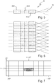
- FIG. 5 shows a horizontal section of a single first (hot spot) microprojector 46 and FIG. 6 shows a horizontal section of a row of first microprojectors 46 along with idealized light beam paths.
- FIG. 7 shows ISO lines of equal intensity in a hot spot low beam distribution generated by several first microprojectors. This draws characterized by an upwardly sharp cut-off and a gentle discharge to the sides with gradual decrease in brightness. On the right side of the abscissa are examples of luminous intensities in candela (cd).
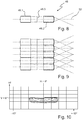
- FIG. 8 shows a horizontal section of a single second (wide spread) microprojector 48 and
- FIG. 9 shows a horizontal section of a row of second microprojectors together with idealized light beam paths.
- FIG. 10 shows ISO lines of equal intensity in a wide spread low beam distribution produced by several second microprojectors. This is characterized by an upwardly sharp cut-off and a gentle discharge to the sides with gradual decrease in brightness. On the right side of the abscissa are examples of luminous intensities in candela (cd).
- the larger cross-sectional profile is responsible for covering a larger decoupling angle.
- the number of wide spread microprojectors is smaller in comparison to the number of hot spot microprojectors with a comparable installation space. Therefore for example, the aperture projections on the street are identical from the light-dark boundaries, but overall they are wider in their horizontal and vertical extension, and thus paler (lower light intensity).
- the light distribution generated by the wide spread microprojectors thus has a quantitatively comparatively weaker maximum at the same point at which the maximum of the hot spot light distribution lies. Towards the sides there is also a gentle outlet.
- FIG. 11 shows a horizontal section of a single third (extra wide spread) microprojector 50 and
- FIG. 12 shows a horizontal section of a row of third microprojectors 50 together with idealized light beam paths.
- FIG. 13 shows ISO lines of equal intensity in one of several third microprojectors generated extra wide spread low beam distribution. This is characterized by an upwardly sharp cut-off and a gentle discharge to the sides with gradual decrease in brightness.
- On the right side of the abscissa are examples of luminous intensities in candela (cd).
- candela candela
- the bright-dark boundaries of the hot spot, wide spread and extra wide spread light distributions in the region of their superposition have an identical course.
- the respective aperture edges are, possibly also different magnified, projected as equal sized images, even if different widths light distributions and bright-dark boundaries are generated by different narrow beam paths.
- the diaphragm edges are also formed (scaled) on the same scale, or all microprojectors have identical imaging scales.
- the optical components of the microprojectors have the following widths B, heights H and depths T and further dimensions: Hot spot lenses: 2.3mm x 1.4mm x 5.0mm (W x H x D) Wide spread lenses: 3.6mm x 2.1mm x 5.0mm (W x H x D) extra wide spread Lenses: 5.0mm x 3.6mm x 5.0mm (W x H x D) Lens distance: 4,0mm Iris thickness: 0.1mm, centered between Input lens and output lens placed focal length of the input lenses: >> 7,0mm Shape of the optical surfaces of the input lenses: (biconic, toric, freeform) Focal length of the starting lenses: about 7,0mm Shape of the optical surfaces of the output lenses: (spherical, aspherical)
- the optical axes of the imaging microprojector lenses determine the optical axes of the respective microprojectors and are arranged parallel or nearly parallel to each other.
- the focal points of the input lens of the microprojectors are downstream of the aperture of the respective microprojector.
- the light exit surfaces of the output lenses of the microprojectors are preferably equally curved.
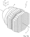
- Figure 14a shows a first light module 54 having only first microprojectors.
- FIG. 14b shows a second light module 56 having only second microprojectors and
- FIG. 14c shows a third light module 58 having only third microprojectors.
- the first light module 54 has only first microprojectors whose first widths are equal and whose first heights are equal.
- the second light module 56 has only second microprojectors whose second widths are equal and whose second heights are equal.
- the third light module 58 has only third microprojectors whose third widths are the same and whose third heights are equal.
- the heights are each parallel to the vertical axis 28.
- the widths are in each case parallel to the transverse axis 30.
- the first widths of the first microprojectors are different from the second widths of the second microprojectors and the third widths of the third microprojectors.
- the first heights of the first microprojectors are different from the second heights of the second microprojectors and the third heights of the third microprojectors.
- Each module consists of a collimating primary optic, an input lens array, an aperture array and an output lens array.
- Each module type has, for example, the dimensions of eg 25mm x 25mm x 30mm (height H x width B x depth T). It is characteristic that the microprojector cross sections for hot spot, wide spread and extra wide spread are of different sizes. The higher light intensity in the hot spot comes with Microprojectors generated whose cross sections are smaller than the cross sections of the wide spread microprojectors. The cross sections of the wide spread microprojectors are smaller than the cross sections of the extra wide spread microprojectors.
- the imaging quality is highest near the common optical axis 52 to about +/- 10 ° to the side thereof. From about +/- 10 °, the image quality, due to the simple design of the projectors, forced by.
- Figure 14d shows an ensemble 60 of such a first light module 54, such a second light module 56 and such a third light module 58.
- the three light modules are preferably used together in a headlamp to form, for example, a low beam distribution consisting of a hot spot component wide spread share and an extra wide spread share.
- the motor vehicle headlight is characterized in that it has microprojectors whose widths are different and whose heights are different.
- a superimposition of several partial light distributions, which are produced with microprojectors of different cross sections, can also be done with a single type of light module be realized.
- FIGS. 15a and 15b show a light module 62 having microprojectors whose widths are different and whose heights are different. It shows the FIG. 15a an exploded along the optical axis 52 representation in the light source 32, primary optics 36, input lens array 64, aperture array 66 and output lens array 68 are clearly separated from each other.
- FIG. 15b shows the light module 62 in a functional mounting state. Fig. 15b shows particularly clearly that microprojectors 46, 48, 50 of different cross sections are present.
- FIGS. 15a . 15 show an example of how row-wise, column-by-column, or different pattern distributed microprojector types 46, 48, 50 are grouped together in a hybrid microprojector array, the term "hybrid" in this application using different microprojectors Cross sections in conjunction with a common collimating primary optics 36 and light source 32.
- hybrid light modules 62 it is possible to assemble different combinations of hot spot, wide spread and extra wide spread microprojectors.
- the different proportions in the total light distribution can be emphasized to different degrees, so that, for example, an overall light distribution with a pronounced maximum or with a larger or smaller horizontal and / or vertical opening angle is generated.
- Different row or column combinations, even mixed lines are conceivable.
- the microprojectors can be placed arbitrarily to each other (preferably parallel or nearly parallel), so that the full cross-section of the collimated by the primary optics light beam of the light source is used.
- a plurality of such hybrid light modules are used in a headlight, each hybrid light module producing a complete, scaled light distribution (scaled: different sizes, but with the same proportions).
- each hybrid light module producing a complete, scaled light distribution (scaled: different sizes, but with the same proportions).
- scaled different sizes, but with the same proportions.
- hybrid light modules 62 microprojectors of different sized cross sections are combined in a single microprojector module 62, so that a hot light source 32 or a collimator 36 are assigned to both hot spot, wide spread and extra wide spread microprojector arrays.
- the total light distribution of such module 62 covers the entire prescribed angular range.
- the total light distribution is defined by the "mixing ratios" of the microprojector cross-section types and can be fine-tuned or steplessly dimmed via the current supply to the light source. Their contrast ratios are ideally preserved.
- the collimating primary optic 36 has a residual divergence in practice.
- the light emanating from the primary optics light source is therefore not completely parallel, but it has an opening angle of a few degrees.
- the cross section of the collimated or bundled Luminous flux has locally different light intensities.
- a microprojector is located in the collimator light bundle, it projects the geometrically identical light-dark boundary image onto the road, but illuminates it differently.
- Each image may have a different focus or is even partially illuminated.
- the total light distribution results as the sum of the individual images. It is true that the superimposition of the individual images eliminates dispersion-related color effects in their entirety.
- the proposed hybrid light module can lead to a simplification and to higher quantities. Only one type of module would be required, rather than having to develop and produce fewer modules for hot spot, wide spread and extra wide spread partial light distributions.
- the dimensions of the active optics of a hybrid light module are, for example, about 25mm x 25mm (height x width) and with a depth of about 30mm. Assuming that three modules were required to produce a low-beam distribution, for example, this would be 25mm x 75mm x 30mm (height x width x depth). Compared with the dimensions of a conventional projection module of approx. 75mm x 75mm x 120mm (height x width x depth), a volume reduction of the order of a factor of 1/12 results.
- the invention allows an impressive space saving (reduction to about 1/100 conceivable) and produces an extremely homogeneous overall light distribution with a sharp cut-off. Due to the modularity and the very good manufacturability and robust operation, there is the advantage of low expected production costs.
Landscapes
- Engineering & Computer Science (AREA)
- General Engineering & Computer Science (AREA)
- Physics & Mathematics (AREA)
- Optics & Photonics (AREA)
- General Physics & Mathematics (AREA)
- Microelectronics & Electronic Packaging (AREA)
- Non-Portable Lighting Devices Or Systems Thereof (AREA)
- Lighting Device Outwards From Vehicle And Optical Signal (AREA)
Abstract
Description
- Die vorliegende Erfindung betrifft einen Kraftfahrzeugscheinwerfer nach dem Oberbegriff des Anspruchs 1. Ein solcher Kraftfahrzeugscheinwerfer ist aus der
WO 2015/058227 A1 bekannt und weist ein Lichtmodul auf, das eine Lichtquelle, eine Licht der Lichtquelle sammelnde Primäroptik und eine Mehrzahl von Mikroprojektoren aufweist, von denen jeder jeweils eine Eingangslinse, eine Ausgangslinse und eine zwischen der Eingangslinse und der Ausgangslinse angeordnete Blende aufweist. Die Eingangslinse, die Blende und die Ausgangslinse weisen eine sich bei bestimmungsgemäßer Verwendung des Kraftfahrzeugscheinwerfers parallel zu einer horizontalen Richtung erstreckende Breite und eine sich parallel zu einer vertikalen Richtung erstreckende Höhe auf. Die Primäroptik, die Eingangslinse, die Blende und die Ausgangslinse jeweils eines Mikroprojektors sind so angeordnet, dass aus der Primäroptik austretendes Licht der Lichtquelle die Eingangslinse beleuchtet und aus der Eingangslinse austretendes Licht der Lichtquelle die Ausgangslinse beleuchtet. - Konventionelle Projektionsmodule für Kraftfahrzeugscheinwerfer weisen eine Optik-Gesamtbautiefe in der Größenordnung von 75 mm bis über 120 mm auf. Unter diese Kategorie fallen Halogen- und Xenon-Scheinwerfer. Lichtquellen beider Kategorien werden im Betrieb mehrere Hundert Grad heiß. In ihrer Nähe stellen sich Temperaturen ein, die mit dem Einsatz feinstrukturierter Kunststoff-Optiken nicht kompatibel sind.
- Erst in den letzten 10 bis 15 Jahren wurde es durch den Einsatz kälterer Lichtquellen, wie z.B. LEDs oder LaserDioden, die eine Betriebstemperatur von maximal 150°C vertragen können, möglich, Kunststoff-Optiken in der Nähe der Lichtquelle zu verwenden. Das machte die Entwicklung komplexerer optischer Ansätze möglich, wie z.B. Voll-LED und/oder Matrix-LED-Scheinwerfer. Solche Ansätze wurden am Anfang ihrer Entwicklung durch diskret aufgebaute Lichtquellenmodule geprägt. Ein Matrix-Scheinwerfer mit einer strukturierten Silikonoptik und einer abbildenden Optik ist aus der
DE 10 2009 053 581 A1 bekannt. - Mit diesen Ansätzen konnten nicht alle Möglichkeiten der Miniaturisierung ausgeschöpft werden, da zur Formung von Matrix-Lichtverteilungen noch vergleichsweise große Primäroptiken und einzelne große Ein-Strahlengang-Projektionsoptiken zum Einsatz kamen. Die Größe der Primäroptiken ist aus Herstellungsgründen nach unten beschränkt. Die sehr komplexen Lichtleiter-basierten Primäroptiken werden in einem Kunststoffspritzvorgang hergestellt, der entsprechend feine Formkavitäten erfordert. Bei komplexen Silikonlichtleitern wird die Verkleinerung zunehmend aufwändig und letztendlich beliebig teuer. Solche Scheinwerfermodule besitzen eine Optik-Bautiefe, die ebenfalls in der Größenordnung von 75 mm bis über 120 mm liegt
- Es ist eine generelle Tendenz, dass der für Kraftfahrzeugscheinwerfer zur Verfügung stehende Bauraum in immer komplexer werdenden Kraftfahrzeugen immer knapper wird. Daraus ergeben sich Forderungen nach einer Miniaturisierung von Kraftfahrzeugscheinwerfern. Es haben sich verschiedene Lösungsansätze ergeben. In einem Lösungsansatz wird die Idee eines Dia- bzw. Kinoprojektors aufgegriffen. Die Lichtverteilung wird durch eine Maske in der Brennfläche eines geeigneten Projektionsobjektivs generiert. Das kann sowohl ein Filter (Dia, LCD) als auch ein feinstrukturiertes Spiegelarray (Digital Light Processing, DLP)sein, welches angeleuchtet wird und durch hochfrequentes Kippen einzelner Mikrospiegel eine dynamische Lichtverteilung generiert, die ebenfalls über ein Projektionsobjektiv abgebildet wird. Entsprechend kann auch eine feinstrukturierte, auf Pixelebene steuerbare integrierte LED-Lichtquelle über ein Projektionsobjektiv abgebildet werden, so dass ihre feinstrukturiert veränderbare Lichtquellenverteilung auf die Fahrbahn projiziert wird.
- In all diesen Fällen wird jeweils ein abbildendes Objektiv verwendet. Eine Verkleinerung des Objektivs würde voraussetzen, dass die Spiegel- oder LED-Arrays entsprechend verkleinert werden können. Einem solchen Vorhaben sind zurzeit technische Grenzen gesetzt, so dass die Verkleinerung solcher Scheinwerfer mit nur einem optischen Strahlengang nicht ausreichend vorangetrieben werden kann. Als Folge ist auch die Bautiefe solcher Scheinwerfer nach unten auf Werte zwischen etwa 60 mm und bis über 100 mm beschränkt.
- Weitere Lösungsansätze sehen vor, nicht die Primäroptik, sondern die abbildende Sekundäroptik zu strukturieren. Derartige Ansätze werden in der
EP 999 407 AT 514 967 AT 514 967 - Bei der eingangs genannten
WO2015/058227A1 wird jeder Einkoppeloptik, bzw. jedem fokussierten Lichtbündel ein Mikroprojektor nachgeschaltet, in den das jeweilige Lichtbündel eintritt. Die Einkoppeloptik übernimmt die Lichtteilung und formt jede der Lichtverteilungen der virtuellen Lichtquellen, die ihr zugeordneter Mikroprojektor auf die Straße projiziert. An den Orten der virtuellen Lichtquellen werden Mikroblenden angeordnet, um damit gewünschte Hell-Dunkel-Grenzen (HDG) zu generieren. - Dabei ist jede abzubildende Lichtverteilung und jede Blende so klein, dass unter Beibehaltung der Abbildgröße, d.h. mit einer Änderung des Abbildungsmaßstabes, eine signifikante Verkürzung der Brennweite und damit der Bautiefe solcher Mikroprojektoren erreicht werden kann. Es handelt sich um eine Verkürzung um den Faktor von ca. 1/3 bis 1/8 im Vergleich zu einem konventionellen Projektor. Maßgeblich für die Verkleinerung sind die Größe der Lichtquelle und ihre Leuchtdichte. Alle abgebildeten Lichtverteilungen überlagern sich auf der Fahrbahn zu einer Gesamtlichtverteilung.
- Nach der
WO2015/058227 A1 werden Lichtbündel, die zu einer Gesamtlichtverteilung überlagert werden, durch von Lichtbündel zu Lichtbündel verschiedene Masken beschnitten (siehe dortFigur 3 und 3b ), um eine Gesamtlichtverteilung mit einer gewünschten Form und Helligkeitsverteilung zu erzeugen (dortFigur 3a ). Faktisch werden dabei zahlreiche überflüssige Hell-Dunkel-Grenzen abgebildet. Wie man dort erkennen kann, überlagern sich die verschieden geformten Teillichtverteilungen zu einer Gesamtlichtverteilung. Nicht jede Teillichtverteilung besitzt die gleiche Hell-Dunkel-Grenze. Zum Beispiel enthält LV2 einen sog. 15°-Anstieg, während LV1, LV3, LV4, LVS (dortFig. 3b ) eine horizontale Hell-Dunkel-Grenze aufweisen. - Wenn man davon ausgeht, dass jede Maske/Blende in der
Figur 3 derWO2015/058227A1 gleich stark beleuchtet wird, ist unmittelbar ersichtlich, dass dort viel Licht abgeschattet wird, was zahlreiche Nachteile mit sich bringt: Um eine vorgegebene Helligkeit auf der Straße zu erzielen, müssen viele Lichtquellen verwendet werden, was teuer ist. Viele Lichtquellen erzeugen auch vergleichsweise viel Wärme, was große und schwere Kühlkörper erfordert. Durch die Überlagerung breiter Grundlichtverteilungen (dort insbesondere LV1) mit einem Abblendlichtspot (dort LV2) kann es auch passieren, dass die größte Helligkeit unnötig weit unterhalb des Horizonts erzielt wird, was die Reichweite nachteilig einschränkt. - Die Lichtverteilung eines Abblendlichtspots mit regelkonformer Hell-Dunkel Grenze erstreckt sich horizontal z.B. nur bis +/-20°H und vertikal z.B. nur von +0,43°V bis -4°V. Um eine komplette Abblendlichtverteilung zusammenzustellen, die Anteile bis z.B. +/-40° horizontal und bis -10° vertikal aufweisen kann, benötigt man eine zusätzliche Grundlicht-Verteilung. Grundlichtmodule leuchten horizontal z.B. +/-40° aus. Dabei erzeugen Grundlichtmodule oft eine durchgezogene horizontale Hell-Dunkel-Grenze die bei Rechtsverkehr links stellenweise nicht höher als -0,57° unter dem Horizont liegen darf. Wegen des horizontalen Verlaufs liegt sie auch rechts nicht höher. Wenn eine solche Grundlichtverteilung in eine Abblendlichtverteilung integriert ist, worin links aber in horizontaler Richtung ab -10° und rechts in horizontaler Richtung ab ca. +1,5° hohe Intensitäten über dem Horizont gefordert werden, bleibt die Hell-Dunkel-Grenze der Grundlichtverteilung links und insbesondere rechts sichtbar und stört die Gesamterscheinung. Außerdem erreicht die Abblendlichtreichweite nur suboptimale Werte, da sich das erforderliche zulässige Helligkeitsmaximum (kleiner als 43.750 cd) eventuell unterhalb des Horizonts, am Übergang zur Grundlichtverteilung, ergibt.
- Ausgehend von der der
WO2015/058227 A1 , die bereits die Forderung zur Bauraumreduktion erfüllt, haben sich die Erfinder die Aufgabe gestellt, einen Kraftfahrzeugscheinwerfer bereitzustellen, der bei nicht größerem Bauraumbedarf effizienter arbeitet als der bekannte Scheinwerfer, eine homogene, farblose Abblendlichtverteilung erzeugt, die einen Winkelumfang von über +/- 40 in horizontaler Richtung und in vertikaler Richtung einen Winkelumfang von +0.57°/-10° für Lichtstärken von mindestens 250 cd aufweist und deren Lichtstärke zur Mitte, also zur optischen Achse hin, im Abblendlichtfall auf die maximal erlaubten 43750 cd ansteigt, ohne dass innerhalb der Lichtverteilung scharfe Helligkeitsunterschiede auftreten. Für Fernlicht (ohne Blende) gelten einfachere Forderungen ohne Hell-Dunkel-Grenze und mit höherem Maximum. Unter einer homogenen Lichtverteilung wird dabei eine Lichtverteilung verstanden, in der, abgesehen von äußeren Rändern, keine scharfen Helligkeitsunterschiede und keine chromatischen Aberrationen auftreten. - Diese Aufgabe wird mit den Merkmalen des Anspruchs 1 gelöst. Dabei unterscheidet sich die Erfindung vom Stand der Technik nach der
WO 2015/058227 A1 durch die kennzeichnenden Merkmale des Anspruchs 1. Diese sehen vor, dass der Kraftfahrzeugscheinwerfer Mikroprojektoren aufweist, deren Breiten unterschiedlich sind und deren Höhen unterschiedlich sind. - Durch die unterschiedlichen Breiten und Höhen ergeben sich Mikroprojektoren mit unterschiedlich großen Querschnitten. Diese Querschnitte bilden die Eingangspupillen der Eingangslinsen. Als Folge werden Lichtbündel unterschiedlicher Breite und Höhe erzeugt, ohne dass dabei mehr Licht abgeschattet wird, als für die Erzeugung einer regelkonformen Standard-Hell-Dunkel-Grenze erforderlich ist. Engere Lichtverteilungskurven (d.h. ISO-Linien gleicher Intensität an einer Messwand) und damit einhergehend höheren Konzentrationen in einem Zentrum (hot spot) können mit Projektionsmodulen kleinerer Querschnitte erzeugt werden.
- Bei gleicher Krümmung der optischen Flächen der Eingangslinsen besitzen die Lichtkegel-Querschnitte, die über die Austrittslinsen austreten, umso geringere Ausdehnungen, je kleiner die Eingangspupillen sind.
- Anstatt mit Hilfe zusätzlich modifizierter Blenden die Lichtkegel-Querschnitte nicht nur zur Formung der vorgeschriebenen HDGs, sondern darüber hinaus zu beschneiden, werden Mikroprojektoren unterschiedlich großer Querschnitte vorgeschlagen. Die vorgeschlagenen Querschnitte sind die Eingangspupillen der Einkoppellinsen jedes einzelnen Projektors. Dadurch werden idealerweise keine extra Lichtanteile geblockt, außer denjenigen Lichtanteilen, die blockiert werden müssen, um die Standard-Hell-Dunkel-Grenze zu erzeugen. Verläufe, Ausläufe und Konzentrationen der Lichtverteilungen werden durch die Krümmungsverhältnisse an der Einkoppellinse und durch die Restdivergenz der Primäroptik, also durch den Öffnungswinkel des aus der Primäroptik austretenden Lichtbündels, beeinflusst.
- Bei gleicher Krümmung der lichtbrechenden Flächen der Eingangslinse nimmt die Ausdehnung der quer zur optischen Achse liegenden Lichtbündelquerschnitte mit kleiner werdenden Eingangspupillen ab. Dann nehmen auch die Lichtkegel-Querschnitte ab, die von den Austrittslinsen auf die Straße projiziert werden. Als Folge besitzen die so auf der Straße erzeugten Lichtverteilungen Ausdehnungen, die durch die Breiten und Höhen der Mikroprojektoren und damit ohne Abschattung konstruktiv vorgegeben werden können.
- Für engere Lichtverteilungskurven (ISO-Linien gleicher Intensität in der Lichtverteilung) und höhere Lichtstärken im Zentrum der Lichtverteilungen (hot spots) kann mit Projektionsmodulen kleinerer Querschnitte gesorgt werden.
- Die kleineren Eingangspupillen bzw. Mikroprojektor-Querschnitte ermöglichen bei gleichem Bauraum eine größere Anzahl von Mikroprojektoren. Entsprechend ergibt sich auch eine größere Anzahl von engeren Teillichtverteilungen, die sich überlappen. Auf dieser Weise wird erreicht, dass die numerische Apertur eines jeden Mikroprojektors verkleinert wird, wodurch chromatische Aberrationen reduziert werden. Der ausgeleuchtete Öffnungswinkel wird kleiner und die gemittelte Lichtstärke im Scheinwerferbündel, bzw. die Beleuchtungsstärke auf der Straße, werden entsprechend der gesteigerten Anzahl von Mikroprojektoren vervielfacht.
- Durch diese Lösung werden keine Lichtanteile unnötig extra geblockt. Die Lichtübertragungseffizienz bleibt im Prinzip erhalten, unabhängig davon, ob eine enge und intensive Lichtverteilung (hot spot) oder ob eine breitere Verteilung geringerer Intensität (wide spread) generiert wird. Die Lichtübertragungseffizienz ist dadurch, anders als bei der
WO 2015/058227 A1 , davon unabhängig, ob eine enge und intensive Lichtverteilung (hot spot) oder ob eine breitere Verteilung geringer Intensität (wide spread) generiert wird. Die Lichtübertragungseffizienz bleibt auf dem üblichen Niveau eines konventionellen Projektionsmoduls. - Dabei verwendet die Erfindung Mikroprojektoren, die eine Realisierung besonders kurzbauender Scheinwerfermodule mittels einer Vielzahl von matrixartig nebeneinander und übereinander angeordneten Mikroprojektoren erlauben.
- Neben dem Vorteil der massiven Bauraumverkleinerung, ermöglicht dieser Ansatz das Erzeugen einer äußerst homogenen, farbneutralen Gesamt-Lichtverteilung mit scharfen Hell-Dunkel-Grenzen und wenig ausgeprägten chromatischen Aberrationen
- Bevorzugt ist auch, dass Brennpunkte der Eingangslinse von wenigstens einem der Mikroprojektoren in einer Ausbreitungsrichtung des aus der Lichtquelle austretenden Lichtes hinter der Blende des wenigstens einen Mikroprojektors liegen. Dabei liegen die Brennpunkte der Eingangslinsen bevorzugt sowohl für die horizontale Richtung als auch für die vertikale Richtung in Richtung der abbildenden Linse stets hinter der als Hell-Dunkel-Grenze abgebildeten Blende. Das ermöglicht eine flexiblere Formung der abzubildenden Lichtverteilung an der Position der als Hell-Dunkel-Grenze abzubildenden Kante der Blende und reduziert ein Übersprechen zu den abbildenden Linsen der benachbarten Mikroprojektoren.
- Weiter ist bevorzugt, dass sich die Eingangslinsen von wenigstens zwei Mikroprojektoren in den Krümmungen ihrer Lichteintrittsflächen und/oder in den Krümmungen ihrer Lichtaustrittsflächen unterscheiden.
- Dadurch ergibt sich ein weiter Gestaltungspielraum beim Entwurf des Lichtmoduls, weil Verläufe, Ausläufe und Konzentrationen der Lichtverteilungen durch die Krümmungsverhältnisse an der Einkoppellinse und der Restdivergenz der Primäroptik beeinflusst werden.
- Eine weitere bevorzugte Ausgestaltung zeichnet sich dadurch aus, dass die Lichtaustrittsflächen der Ausgangslinsen von wenigstens zwei der Mikroprojektoren gleich stark gekrümmt sind.
- Für die abbildenden Ausgangslinsen ergeben sich dann identische optische Grundflächen. Das führt dazu, dass die Ausgangslinsen die Blenden, bzw. die am Blendenort herrschende Lichtverteilung, idealerweise als gleichgroße Bilder auf die Straße abbilden.
- Die Blenden könnten aber auch skaliert (unterschiedlich groß aber mit gleichen Proportionen) sein. In diesem Fall würden sich die Ausgangslinsen, ihre Grundflächen und Brennweiten so unterscheiden, dass über die Anpassung des Abbildungsmaßstabs gleichgroße Blenden-Bilder auf die Straße projiziert werden. Im Fernlichtfall fällt die Blende aus, die restlichen Voraussetzungen werden aufrechterhalten, so dass die lokale Lichtverteilung an der fehlenden Blendenposition über die Auskoppellinse auf die Straße projiziert wird.
- Bevorzugt ist auch, dass der Kraftfahrzeugscheinwerfer erste Mikroprojektoren aufweist, die eine erste Breite und eine erste Höhe aufweisen, zweite Mikroprojektoren aufweist, die eine zweite Breite und eine zweite Höhe aufweisen, und dritte Mikroprojektoren aufweist, die eine dritte Breite und eine dritte Höhe aufweisen.
- Ein solcher Scheinwerfer eignet sich dazu, verschiedene Teillichtverteilungen zu erzeugen, in denen die Helligkeit unterschiedlich breit verteilt ist, so dass sich durch Überlagerung Lichtverteilungen mit breiten Anteilen (wide spread) und mit weitreichenden Anteilen (hot spot) erzeugen lassen. Somit deckt die Gesamtlichtverteilung des Scheinwerfers den kompletten vorgeschriebenen Winkelbereich einer regelkonformen Lichtverteilung ab. Die Gesamtlichtverteilung wird durch die "Mischungsverhältnisse" der Mikroprojektor-Querschnitt-Typen definiert. Zu diesem Zweck kann der Scheinwerfer ein Hybridlichtmodul aufweisen, das verschiedene Typen von Mikroprojektoren aufweist, oder er kann mehrere Lichtmodule aufweisen, von denen jedes nur einen Typ von Mikroprojektoren aufweist, wobei die unterschiedlichen Lichtmodule unterschiedliche Typen von Mikroprojektoren aufweisen.
- Eine weitere bevorzugte Ausgestaltung zeichnet sich dadurch aus, dass der Kraftfahrzeugscheinwerfer mehrere Lichtmodule aufweist, welche die Merkmale des Lichtmoduls aus dem Anspruch 1 aufweisen. Weiter ist bevorzugt, dass sich die Eingangslinsen von wenigstens zwei Mikroprojektoren in den Krümmungen ihrer Lichteintrittsflächen und/oder in den Krümmungen ihrer Lichtaustrittsflächen unterscheiden.
- Eine weitere bevorzugte Ausgestaltung zeichnet sich dadurch aus, dass ein erstes Lichtmodul der mehreren Lichtmodule nur erste Mikroprojektoren aufweist, deren Breiten gleich sind und deren Höhen gleich sind, und dass ein zweites der mehreren Lichtmodule nur zweite Mikroprojektoren aufweist, deren Breiten gleich sind und deren Höhen gleich sind, wobei sich die Breiten der ersten Mikroprojektoren von den Breiten der zweiten Mikroprojektoren unterscheiden und sich die Höhen der ersten Mikroprojektoren von den Höhen der zweiten Mikroprojektoren unterscheiden.
- Weiter ist bevorzugt, dass ein Lichtmodul Mikroprojektoren aufweist, deren Breiten unterschiedlich sind und deren Höhen unterschiedlich sind.
- Ein solches Hybridlichtmodul eignet sich dazu, mit nur einer Lichtquelle und einer Primäroptik verschiedene Teillichtverteilungen zu erzeugen, in denen die Helligkeit unterschiedlich breit verteilt ist, so dass sich durch Überlagerung Lichtverteilungen mit breiten Anteilen (wide spread) und mit weitreichenden Anteilen (hot spot) erzeugen lassen. Somit deckt die Gesamtlichtverteilung eines solchen Hybridlichtmoduls den kompletten vorgeschriebenen Winkelbereich einer regelkonformen Lichtverteilung ab. Die Gesamtlichtverteilung wird durch die "Mischungsverhältnisse" der Mikroprojektor-Querschnitt-Typen definiert und kann über die Bestromung der Lichtquelle feinstufig bzw. stufenlos gedimmt werden. Ihre Kontrastverhältnisse bleiben dabei idealerweise erhalten.
- Bevorzugt ist auch, dass eine Summe der Breiten von nebeneinander angeordneten Mikroprojektoren eines Lichtmoduls kleiner als 30 mm ist und dass eine Summe der Höhen übereinander angeordneter Mikroprojektoren eines Lichtmoduls kleiner als 30 mm ist.
- Eine weitere bevorzugte Ausgestaltung zeichnet sich dadurch aus, dass die Breiten der Mikroprojektoren kleiner als 6 mm sind, die Höhen der Mikroprojektoren kleiner als 4 mm sind und die Tiefe jeweils einer Linse der Mikroprojektoren kleiner als 6 mm ist.
- Bevorzugt ist auch, dass der Kraftfahrzeugscheinwerfer mehrere Lichtmodule aufweist, welche die in dem Anspruch 1 genannten Merkmale aufweisen, wobei die lichtsammelnden Primäroptiken von wenigstens zwei der Lichtmodule das in sie eintretende Licht unterschiedlich stark bündeln.
- Mit dieser Ausgestaltung lässt sich die Lichtverteilung zusätzlich beeinflussen.
- Weitere Vorteile ergeben sich aus den abhängigen Ansprüchen, der Beschreibung und den beigefügten Figuren.
- Es versteht sich, dass die vorstehend genannten und die nachstehend noch zu erläuternden Merkmale nicht nur in der jeweils angegebenen Kombination, sondern auch in anderen Kombinationen oder in Alleinstellung verwendbar sind, ohne den Rahmen der vorliegenden Erfindung zu verlassen.
- Ausführungsbeispiele der Erfindung sind in den Zeichnungen dargestellt und werden in der nachfolgenden Beschreibung näher erläutert. Dabei bezeichnen gleiche Bezugszeichen in verschiedenen Figuren jeweils gleiche oder zumindest ihrer Funktion nach vergleichbare Elemente. Es zeigen, jeweils in schematischer Form:
- Figur 1
- eine Überlagerung von drei Fernlichtverteilungen;
- Figur 2
- dazu korrespondierende Abblendlichtverteilungen;
- Figur 3
- ein Ausführungsbeispiel eines erfindungsgemäßen Kraftfahrzeugscheinwerfers;
- Figur 4
- Mikroprojektoren in einer perspektivischen Darstellung;
- Figur 5
- einen horizontalen Schnitt eines einzelnen ersten (hot spot) Mikroprojektors;
- Figur 6
- einen horizontalen Schnitt einer Zeile von ersten Mikroprojektoren zusammen mit idealisierten Lichtbündelverläufen;
- Figur 7
- zeigt ISO-Linien gleicher Intensität in einer von mehreren ersten Mikroprojektoren erzeugten hot spot Abblendlichtverteilung.
- Figur 8
- einen horizontalen Schnitt eines einzelnen zweiten (wide spread) Mikroprojektors;
- Figur 9
- einen horizontalen Schnitt einer Zeile von zweiten Mikroprojektoren zusammen mit idealisierten Lichtbündelverläufen;
- Figur 10
- ISO-Linien gleicher Intensität in einer von mehreren zweiten Mikroprojektoren erzeugten wide spread Abblendlichtverteilung;
- Figur 11
- einen horizontalen Schnitt eines einzelnen dritten (extra wide spread) Mikroprojektors;
- Figur 12
- einen horizontalen Schnitt einer Zeile von dritten Mikroprojektoren zusammen mit idealisierten Lichtbündelverläufen;
- Figur 13
- ISO-Linien gleicher Intensität in einer von mehreren dritten Mikroprojektoren erzeugten extra wide spread Abblendlichtverteilung.
- Figur 14
- verschiedene Lichtmodule und ein Ensemble dieser Lichtmodule; und
- Figur 15
- ein Hybridlichtmodul, das Mikroprojektoren aufweist, deren Breiten unterschiedlich sind und deren Höhen unterschiedlich sind.
-
Figur 1 zeigt im Einzelnen rein qualitativ eine Überlagerung von drei Fernlichtverteilungen 10, 12, 14, wie sie sich auf einem senkrecht vor einem Scheinwerfer stehenden Schirm einstellen, zusammen mit der Angabe einer vertikalen Richtung V und der Angabe eine horizontalen Richtung H. Die breiteste der drei Lichtverteilungen wird im Folgenden auch als extra wide spread Fernlichtverteilung 10 bezeichnet. Die nächstschmalere Fernlichtverteilung wird im Folgenden auch als wide spread Fernlichtverteilung 12, und die schmalste der drei Lichtverteilungen wird im Folgenden auch als hot spot Lichtverteilung 14 bezeichnet. -
Figur 2 zeigt dazu korrespondierende Abblendlichtverteilungen 16, 18, 20 mit einer für alle drei Abblendlichtverteilungen 16, 18, 20 im Überlagerungsbereich deckungsgleichen Hell-Dunkel-Grenze 22. Die breiteste der drei Lichtverteilungen wird im Folgenden auch als extra wide spread Abblendlichtverteilung 16 bezeichnet. Die nächstschmalere Lichtverteilung wird im Folgenden auch als wide spread Abblendlichtverteilung 18, und die schmalste der drei Lichtverteilungen wird im Folgenden auch als hot spot Abblendlichtverteilung 20 bezeichnet. -
Figur 3 zeigt ein Ausführungsbeispiel eines erfindungsgemäßen Kraftfahrzeugscheinwerfers 24, in einem seitlichen Schnitt. Bei einer bestimmungsgemäßen Verwendung des Scheinwerfers 24 in einem Kraftfahrzeug wird die Schnittebene von der Richtung 26 einer Längsachse und der Richtung 28 einer Hochachse des Kraftfahrzeugs aufgespannt. Die Richtung 30 einer Querachse des Kraftfahrzeugs steht senkrecht auf der Schnittebene. Der Scheinwerfer 24 weist ein Lichtmodul 30 auf, das eine Lichtquelle 32, eine Licht 34 der Lichtquelle 32 sammelnde und parallelisierende Primäroptik 36 und eine Mehrzahl von Mikroprojektoren 38 aufweist. Die Lichtquelle 32 ist eine Halbleiterlichtquelle, bevorzugt eine Leuchtdiode oder Laserdiode, oder ein mehrere solcher Dioden aufweisendes array. Das Lichtmodul ist in einem Gehäuse 24.1 des Scheinwerfers 24 angeordnet. Eine Lichtaustrittsöffnung des Scheinwerfers wird von einer transparenten Abdeckscheibe 24.2 abgedeckt. - Die Mikroprojektoren 38 unterscheiden sich zum Teil in ihrer parallel zur Richtung der Hochachse 28 in
Figur 1 liegenden Höhe. Erste Mikroprojektoren weisen eine kleine Höhe h1 auf. Diese Mikroprojektoren dienen zur Erzeugung einer hot spot Lichtverteilung. Zweite Mikroprojektoren weisen eine mittlere Höhe h2 auf. Diese Mikroprojektoren dienen zur Erzeugung einer wide spread Lichtverteilung. Dritte Mikroprojektoren weisen eine große Höhe h3 auf. Diese Mikroprojektoren dienen zur Erzeugung einer extra wide spread Lichtverteilung. Die Begriffe klein, mittel und groß werden hier zur qualitativen Unterscheidung der drei verschieden hohen Mikroprojektoren verwendet und sind daher nicht als auf bestimmte Werte quantitativ beschränkt zu verstehen. - Jeder Mikroprojektor 38 weist eine Eingangslinse 40, eine Blende 42 (gilt für Abblendlichtmikroprojektoren) und eine Ausgangslinse 44 auf. Die Stirnseiten der Ein- und Auskoppelflächen haben dieselben Abstände von der Blendenfläche, sowohl für hot spot als auch für wide spread und extra wide spread Mikroprojektoren. Daraus ergibt sich, dass auch die Vergrößerungsfaktoren dieser Mikroprojektoren gleich sind. Die Mikroprojektoren erzeugen damit ungleich große Bilder im Fernfeld. Eine Helligkeitsverteilung im Fernfeld ergibt sich durch die Überlagerung verschieden großer Bilder. Wenn die Abstände nicht gleich, sondern verschieden wären, würde dies Skalierungen der Blenden erfordern. Größere Abstände vergrößern die Brennweite und verkleinern den Öffnungswinkel des Austrittslichtkegels.
- Bei der Erfindung werden verschieden große Lichtbündelquerschnitte, die in das Fernfeld abgebildet werden, nur durch verschiedene Größen der Eingangspupillen der Mikroprojektoren erzeugt. Die Blenden 42 dienen lediglich zur Formung der Hell-Dunkel-Grenze. Schmale Lichtverteilungen im Fernfeld werden durch enge Eingangspupillen erzeugt (z.B. hot spot). Hohe Intensitäten werden durch Überlagerung vieler schmaler Lichtverteilungen erzeugt, also durch Überlagerung der Beiträge von vergleichsweise vielen Mikroprojektoren erzeugt. Breite Lichtverteilungen im Fernfeld werden durch weite Eingangspupillen erzeugt (z.B. wide spread, extra wide spread). Niedrige Intensitäten werden durch Überlagerung der Beiträge von weniger Mikroprojektoren erzeugt.
-
Figur 4 zeigt die Mikroprojektoren jeweils in einer perspektivischen Darstellung in gleichem Maßstab und in einer für einen Größenvergleich gedanklichen Überlagerung. Dabei zeigtFigur 4a einen ersten Mikroprojektor 46,Figur 4b einen zweiten Mikroprojektor 48,Figur 4c einen dritten Mikroprojektor 50, undFigur 4d zeigt die gedankliche Überlagerung der drei Mikroprojektoren 46, 48, 50. Jede derFiguren 4a bis 4d zeigt auch eine optische Achse 52. Die optische Achse 52 besitzt bei bestimmungsgemäßer Verwendung des Scheinwerfers die Richtung der Längsachse des Kraftfahrzeugs. - Jeder der Mikroprojektoren weist eine Eingangslinse 46.1, 48.1, 50.1, eine Ausgangslinse 46.2, 48.2, 50.2 und eine zwischen der Eingangslinse und der Ausgangslinse angeordnete Blende 46.3, 48.3, 50.3 auf. Die Eingangslinsen und die Blenden besitzen jeweils eine sich bei der bestimmungsgemäßen Verwendung des Kraftfahrzeugscheinwerfers 10 parallel zu einer horizontalen Richtung erstreckende Breite b und eine sich parallel zu der vertikalen Richtung erstreckende Höhe h.
- Dies gilt analog für die Ausgangslinsen. Jede Ausgangslinse eines Mikroprojektors weist bevorzugt dieselbe Breite b und dieselbe Höhe h auf wie die zugehörige Eingangslinse des Mikroprojektors. Die Primäroptik und die Eingangslinse, Blende und Ausgangslinse jeweils eines Mikroprojektors sind so angeordnet, dass aus der Primäroptik austretendes Licht der Lichtquelle die Eingangslinse beleuchtet und aus der Eingangslinse austretendes Licht der Lichtquelle die Ausgangslinse beleuchtet. Die Mikroprojektoren zeichnen sich dadurch aus, dass ihre Breiten unterschiedlich sind und ihre Höhen unterschiedlich sind.
-
Figur 5 zeigt einen horizontalen Schnitt eines einzelnen ersten (hot spot) Mikroprojektors 46 undFigur 6 zeigt einen horizontalen Schnitt einer Zeile von ersten Mikroprojektoren 46 zusammen mit idealisierten Lichtbündelverläufen.Figur 7 zeigt ISO-Linien gleicher Intensität in einer von mehreren ersten Mikroprojektoren erzeugten hot spot Abblendlichtverteilung. Diese zeichnet sich durch eine nach oben scharfe Hell-Dunkel-Grenze und einen zu den Seiten sanften Auslauf mit allmählichem Absinken der Helligkeit aus. An der rechten Abscisse sind Beispiele von Lichtstärken in candela (cd) angegeben. - Dank ihrer kleinen Abmessungen liegen die örtlichen Verschiebungen in der Überlappung zu einer gemeinsamen Lichtverteilungskurve auf der Straße in der Größenordnung der einzelnen Mikroprojektor-Abmessungen. Diese liegen also im Millimeterbereich und sind deutlich kleiner als die örtliche Querschnittsausdehnung ihrer Lichtkegel auf der Straße. Eine solch geringe örtliche Verschiebung übt nahezu keinen Einfluss auf die Schärfe der Hell-Dunkel-Grenze aus und trägt höchstens zur besseren Farbdurchmischung, bzw. Homogenisierung der gemeinsamen Lichtverteilungskurve bei.
-
Figur 8 zeigt einen horizontalen Schnitt eines einzelnen zweiten (wide spread) Mikroprojektors 48 undFigur 9 zeigt einen horizontalen Schnitt einer Zeile von zweiten Mikroprojektoren zusammen mit idealisierten Lichtbündelverläufen. -
Figur 10 zeigt ISO-Linien gleicher Intensität in einer von mehreren zweiten Mikroprojektoren erzeugten wide spread Abblendlichtverteilung. Diese zeichnet sich durch eine nach oben scharfe Hell-Dunkel-Grenze und einen zu den Seiten sanften Auslauf mit allmählichem Absinken der Helligkeit aus. An der rechten Abscisse sind Beispiele von Lichtstärken in candela (cd) angegeben. - Das größere Querschnittsprofil (Eingangspupille) ist verantwortlich für die Abdeckung eines größeren Auskoppelwinkels. Die Anzahl der wide spread Mikroprojektoren ist im Vergleich zur Anzahl von hot spot Mikroprojektoren bei vergleichbarem Bauraum kleiner. Daher sind die Blendenprojektionen auf der Straße vom Verlauf der Hell-Dunkel-Grenzen her zwar identisch, insgesamt jedoch in ihrer horizontalen und vertikalen Ausdehnung breiter und folglich blasser (geringere Lichtstärke). Die von den wide spread Mikroprojektoren erzeugte Lichtverteilung besitzt also ein quantitativ vergleichsweise schwächeres Maximum an der gleichen Stelle, an der auch das Maximum der hot spot Lichtverteilung liegt. Zu den Seiten hin ergibt sich auch hier ein sanfter Auslauf.
-
Figur 11 zeigt einen horizontalen Schnitt eines einzelnen dritten (extra wide spread) Mikroprojektors 50 undFigur 12 zeigt einen horizontalen Schnitt einer Zeile von dritten Mikroprojektoren 50 zusammen mit idealisierten Lichtbündelverläufen. -
Figur 13 zeigt ISO-Linien gleicher Intensität in einer von mehreren dritten Mikroprojektoren erzeugten extra wide spread Abblendlichtverteilung. Diese zeichnet sich durch eine nach oben scharfe Hell-Dunkel-Grenze und einen zu den Seiten sanften Auslauf mit allmählichem Absinken der Helligkeit aus. An der rechten Abscisse sind Beispiele von Lichtstärken in candela (cd) angegeben. Auch hier gilt, dass die Hell-Dunkel-Grenzen der hot spot, wide spread und extra wide spread Lichtverteilungen im Bereich ihrer Überlagerung einen identischen Verlauf besitzen. Die jeweiligen Blendenkanten werden, möglicherweise auch unterschiedlich vergrößert, als gleich große Abbildungen projiziert, auch wenn durch verschieden enge Strahlengänge verschieden breite Lichtverteilungen und Hell-Dunkel-grenzen erzeugt werden. Bei gleicher Brennweite der abbildenden Mikrolinsen sind auch die Blendenkanten in gleichem Maßstab ausgebildet (skaliert), bzw. alle Mikroprojektoren haben identische Abbildungsmaßstäbe. - In einem Ausführungsbeispiel weisen die optischen Komponenten der Mikroprojektoren folgende Breiten B, Höhen H und Tiefen T und weitere Abmessungen auf:
Hot spot-Linsen: 2,3mm x 1,4mm x 5,0mm (B x H x T) Wide spread-Linsen: 3,6mm x 2,1mm x 5,0mm (B x H x T) extra wide spread Linsen: 5,0mm x 3,6mm x 5,0 mm (B x H x T) Linsenabstand: 4,0mm Blendendicke: 0,1mm, mittig zwischen Eingangslinse und Ausgangslinse platziert Brennweite der Eingangslinsen: >> 7,0mm Form der optischen Flächen der Eingangslinsen: (bikonisch, torisch, freiform) Brennweite der Ausgangslinsen: ca. 7,0mm - Die optischen Achsen der abbildenden Mikroprojektorlinsen (sphärisch, asphärisch) bestimmen die optischen Achsen der jeweiligen Mikroprojektoren und sind parallel oder nahezu parallel zueinander angeordnet. Je schmäler einzelne Mikroprojektoren sind, desto geringer sind die Öffnungswinkel einzelner Mikrobündel trotz kurzer Brennweiten. Das gilt insbesondere für die hot spot-Mikroprojektoren. Dadurch tritt weniger Farbdispersion an den Linsenrändern auf.
- Wie aus den
Figuren 5 ,8 und11 ersichtlich ist, liegen die Brennpunkte der Eingangslinse der Mikroprojektoren lichtstromabwärts der Blende des jeweiligen Mikroprojektors. - Die Lichtaustrittsflächen der Ausgangslinsen der Mikroprojektoren sind bevorzugt gleich stark gekrümmt.
-
Figur 14a zeigt ein erstes Lichtmodul 54, das nur erste Mikroprojektoren aufweist.Figur 14b zeigt ein zweites Lichtmodul 56, das nur zweite Mikroprojektoren aufweist undFigur 14c zeigt ein drittes Lichtmodul 58, das nur dritte Mikroprojektoren aufweist. - Das erste Lichtmodul 54 weist nur erste Mikroprojektoren auf, deren erste Breiten gleich sind und deren erste Höhen gleich sind. Das zweite Lichtmodul 56 weist nur zweite Mikroprojektoren auf, deren zweite Breiten gleich sind und deren zweite Höhen gleich sind. Das dritte Lichtmodul 58 weist nur dritte Mikroprojektoren auf, deren dritte Breiten gleich sind und deren dritte Höhen gleich sind. Die Höhen liegen jeweils parallel zur Hochachse 28. Die Breiten liegen jeweils parallel zur Querachse 30.
- Die ersten Breiten der ersten Mikroprojektoren unterscheiden sich von den zweiten Breiten der zweiten Mikroprojektoren und den dritten Breiten der dritten Mikroprojektoren. Die ersten Höhen der ersten Mikroprojektoren unterscheiden sich von den zweiten Höhen der zweiten Mikroprojektoren und den dritten Höhen der dritten Mikroprojektoren.
- Es entstehen auf diese Weise z.B. drei Modul-Typen: hot spot, wide spread und extra wide spread. Jedes Modul besteht aus einer kollimierenden Primäroptik, einem Eingangslinsen-Array, einem Blenden-Array und einem Ausgangslinsen-Array.
- Jeder Modultyp hat beispielsweise die Maße von z.B. 25mm x 25mm x 30mm (Höhe H x Breite B x Tiefe T). Charakteristisch ist, dass die Mikroprojektor-Querschnitte für hot spot, wide spread und extra wide spread unterschiedlich groß sind. Die höhere Lichtstärke im hot spot wird mit Mikroprojektoren erzeugt, deren Querschnitte kleiner als die Querschnitte der wide spread-Mikroprojektoren sind. Die Querschnitte der wide spread-Mikroprojektoren sind kleiner als die Querschnitte der extra wide spread-Mikroprojektoren. Die Abbildungsqualität ist nahe der gemeinsamen optischen Achse 52 bis etwa +/-10° seitlich davon am höchsten. Ab etwa +/-10° nimmt die Abbildungsqualität, bedingt durch den einfachen Aufbau der Projektoren, gezwungenermaßen ab.
- Durch die gute Abbildungsqualität ergeben sich bei entsprechender Justage der einzelnen Module zueinander homogene, nahtlose Überlappungen der Lichtverteilungen, so dass die aus der Überlagerung resultierende Gesamtlichtverteilung als eine insgesamt homogene und farbkompensierte Lichtverteilung wahrgenommen werden kann. Zwischen den einzelnen Teillichtverteilungen treten keine sprunghaften Helligkeitsunterschiede auf.
-
Figur 14d zeigt ein Ensemble 60 eines solchen ersten Lichtmoduls 54, eines solchen zweiten Lichtmoduls 56 und eines solchen dritten Lichtmoduls 58. Die drei Lichtmodule werden bevorzugt gemeinsam in einem Scheinwerfer verwendet, um zum Beispiel eine Abblendlichtverteilung zu bilden, die sich aus einem hot spot Anteil, einem wide spread Anteil und einem extra wide spread Anteil zusammensetzt. - In einer bevorzugten Ausgestaltung zeichnet sich der Kraftfahrzeugscheinwerfer dadurch aus, dass er Mikroprojektoren aufweist, deren Breiten unterschiedlich sind und deren Höhen unterschiedlich sind.
- Eine Überlagerung von mehreren Teillichtverteilungen, die mit Mikroprojektoren unterschiedlicher Querschnitte erzeugt werden, kann auch mit einem einzigen Lichtmodultyp verwirklicht werden.
- Die
Figuren 15a und15b zeigen ein Lichtmodul 62, das Mikroprojektoren aufweist, deren Breiten unterschiedlich sind und deren Höhen unterschiedlich sind. Dabei zeigt dieFigur 15a eine längs der optischen Achse 52 auseinander gezogene Darstellung, in der Lichtquelle 32, Primäroptik 36, Eingangslinsenarray 64, Blendenarray 66 und Ausgangslinsenarray 68 voneinander getrennt deutlich erkennbar sind.Figur 15b zeigt das Lichtmodul 62 in einem funktionsfähigen Montagezustand.Fig. 15b zeigt besonders deutlich, dass Mikroprojektoren 46, 48, 50 unterschiedlicher Querschnitte vorhanden sind. - Die
Figuren 15a ,15 zeigen ein Beispiel dafür, wie zeilen- oder spaltenweise, oder nach einem anderen Muster verteilte verschiedene Mikroprojektor-Typen 46, 48, 50 in einem hybriden Mikroprojektor-Array zusammengefasst werden, wobei der Begriff "Hybrid" in dieser Anmeldung die Verwendung von Mikroprojektoren mit unterschiedlichen Querschnitten in Verbindung mit einer gemeinsamen kollimierenden Primäroptik 36 und Lichtquelle 32 umschreibt. Durch die Verwendung von Hybridlichtmodulen 62 ist es möglich, verschiedene Kombinationen aus hot spot, wide spread und extra wide spread Mikroprojektoren zusammenzustellen. So können die verschiedenen Anteile in der Gesamtlichtverteilung unterschiedlich stark betont werden, so dass zum Beispiel eine Gesamtlichtverteilung mit einem ausgeprägten Maximum oder mit größerem oder kleinerem horizontalen und/oder vertikalen Öffnungswinkel erzeugt werden. Unterschiedliche Zeilen- oder Spaltenkombinationen, sogar Mischzeilen sind denkbar. Die Mikroprojektoren können beliebig zueinander platziert werden (bevorzugt parallel oder nahezu parallel), so dass der volle Querschnitt des von der Primäroptik kollimierten Lichtbündels der Lichtquelle genutzt wird. - Über die bei der Konstruktion separat festlegbaren Werte der Höhen und Breiten der einzelnen Mikroprojektoren ist es möglich, die Anteile der daraus resultierenden Teillichtverteilungen in der Überlagerung der einzelnen Teillichtverteilungen zu steuern, so dass sich in der Überlagerung ein erwünschter Verlauf der Lichtstärke in horizontaler und in vertikaler Richtung ergibt.
- In einer bevorzugten Ausgestaltung werden in einem Scheinwerfer mehrere solcher Hybridlichtmodule verwendet, wobei jedes Hybridlichtmodul eine vollständige, skalierte Lichtverteilung erzeugt (skaliert: unterschiedlich groß, aber mit gleichen Proportionen). Somit ist es möglich, mit beispielsweise zwei bis drei gleichen Hybridlichtmodulen die erforderliche Lichtverteilung über eine passende Bestromung der Lichtquellen zu generieren.
- Bei den Hybridlichtmodulen 62 werden Mikroprojektoren verschieden großer Querschnitte in einem einzelnen Mikroprojektor-Modul 62 zusammengefasst, so dass einer Lichtquelle 32 bzw. einem Kollimator 36 sowohl hot spot, wide spread und extra wide spread-Mikroprojektorarrays zugeordnet werden. Somit deckt die Gesamtlichtverteilung eines solchen Moduls 62 den kompletten vorgeschriebenen Winkelbereich ab. Die Gesamtlichtverteilung wird durch die "Mischungsverhältnisse" der Mikroprojektor-Querschnitt-Typen definiert und kann über die Bestromung der Lichtquelle feinstufig bzw. stufenlos gedimmt werden. Ihre Kontrastverhältnisse bleiben dabei idealerweise erhalten.
- Die kollimierende Primäroptik 36 weist in der Praxis eine Restdivergenz auf. Das von der Primäroptik ausgehende Licht der Lichtquelle ist daher nicht vollständig parallel, sondern es weist einen Öffnungswinkel von wenigen Grad auf. Der Querschnitt des kollimierten bzw. gebündelten Lichtstromes weist örtlich unterschiedliche Lichtstärken auf. Das führt dazu, dass, je nachdem, an welcher Position sich ein Mikroprojektor im Kollimator-Lichtbündel befindet, er das geometrisch gleiche Hell-Dunkel-Grenzen-Bild auf die Straße projiziert, jedoch unterschiedlich ausgeleuchtet. Jede Abbildung hat eventuell einen anderen Lichtschwerpunkt oder ist sogar nur teilweise ausgeleuchtet. Entsprechend des Superpositionsprinzips ergibt sich die Gesamtlichtverteilung als Summe der Einzelbilder. Es gilt, dass sich durch die Überlagerung der Einzelbilder dispersionsbedingte Farbeffekte in ihrer Gesamtheit aufheben.
- In der Produktion kann das vorgeschlagene Hybridlichtmodul zu einer Vereinfachung und zu höheren Stückzahlen führen. Nur ein Modultyp wäre erforderlich, statt verschiedene Module für hot spot, wide spread und extra wide spread-Teillichtverteilungen entwickeln und in kleinerer Anzahl herstellen zu müssen.
- Die Abmessungen der aktiven Optik eines Hybridlichtmoduls liegen beispielsweise bei ca. 25mm x 25mm (Höhe x Breite) und bei einer Bautiefe von ca. 30mm. Angenommen, drei Module würden zur Erzeugung einer Abblendlichtverteilung erforderlich sein, ergäben sich beispielsweise 25mm x 75mm x 30mm (Höhe x Breite x Tiefe). Verglichen mit den Abmessungen eines konventionellen Projektionsmoduls von ca. 75mm x 75mm x 120mm (Höhe x Breite x Tiefe) ergibt sich eine Volumenverkleinerung in der Größenordnung eines Faktors 1/12.
- Das Potenzial dieser Technologie ist damit bei Weitem nicht erschöpft. Denkbar ist es, solche Hybridlichtmodule zweifach linear zu skalieren, was einem weiteren Volumenskalierungsfaktor von 1/8 entspricht. Dadurch wären Volumen-Skalierungen von 1/(12 x 8) = 1/96 bezogen auf ein konventionelles Projektionssystem möglich. Selbstverständlich werden auch andere Faktoren wie Wärme, Kühlung, LED-Lichtfluss, Steuer-Elektronik und Herstellbarkeit die Skalierung beeinflussen bzw. ihr entgegenwirken. Dennoch eröffnet die vorliegende Erfindung neue Möglichkeiten der Miniaturisierung, für lichttechnische Innovation und Qualitätssteigerung, zur Umsetzung moderner Design-Ideen für neue Akzente in der Wahrnehmung, sowie zur Kostenreduktion und Wertsteigerung kommender Scheinwerfergenerationen.
- Die Erfindung ermöglicht eine beeindruckende Bauraumeinsparung (Verkleinerung bis ca. 1/100 denkbar) und erzeugt eine extrem homogene Gesamtlichtverteilung mit einer scharfen Hell-Dunkel-Grenze. Durch die Modularität und die sehr gute Herstellbarkeit und robuste Funktionsweise ergibt sich der Vorteil niedrig zu erwartender Produktionskosten.
Claims (10)
- Kraftfahrzeugscheinwerfer (24) mit einem Lichtmodul (30), das eine Lichtquelle (32), eine Licht (34) der Lichtquelle (32) sammelnde Primäroptik (36) und eine Mehrzahl von Mikroprojektoren (38) aufweist, von denen jeder jeweils eine Eingangslinse (40, eine Ausgangslinse (44) und eine zwischen der Eingangslinse und der Ausgangslinse angeordnete Blende (42) aufweist, wobei die Eingangslinse (40), die Blende (42) und die Ausgangslinse (44) eine sich bei bestimmungsgemäßer Verwendung des Kraftfahrzeugscheinwerfers (24) parallel zu einer horizontalen Richtung (30) erstreckende Breite (b) und eine sich parallel zu einer vertikalen Richtung (28) erstreckende Höhe (h) aufweisen, wobei die Primäroptik (36), die Eingangslinse (40), die Blende (42) und die Ausgangslinse (44) jeweils eines Mikroprojektors (38) so angeordnet sind, dass aus der Primäroptik (36) austretendes Licht der Lichtquelle (32) die Eingangslinse (40) beleuchtet und aus der Eingangslinse (40) austretendes Licht der Lichtquelle (32) die Ausgangslinse (44) beleuchtet, dadurch gekennzeichnet, dass der Kraftfahrzeugscheinwerfer (24) Mikroprojektoren (46, 48, 50) aufweist, deren Breiten (b) unterschiedlich sind und deren Höhen (h) unterschiedlich sind.
- Kraftfahrzeugscheinwerfer (24) nach Anspruch 1, dadurch gekennzeichnet, dass Brennpunkte der Eingangslinse von wenigstens einem der Mikroprojektoren in einer Ausbreitungsrichtung des aus der Eingangslinse austretenden Lichtes der Lichtquelle hinter der Blende des wenigstens einen Mikroprojektors liegen.
- Kraftfahrzeugscheinwerfer (24) nach einem der vorhergehenden Ansprüche, dadurch gekennzeichnet, dass die Lichtaustrittsflächen der Ausgangslinsen von wenigstens zwei der Mikroprojektoren gleich stark gekrümmt sind.
- Kraftfahrzeugscheinwerfer (24) nach einem der vorhergehenden Ansprüche, dadurch gekennzeichnet, dass der Kraftfahrzeugscheinwerfer (24) erste Mikroprojektoren (46) aufweist, die eine erste Breite und eine erste Höhe aufweisen, zweite Mikroprojektoren (48) aufweist, die eine zweite Breite und eine zweite Höhe aufweisen, und dritte Mikroprojektoren (50) aufweist, die eine dritte Breite und eine dritte Höhe aufweisen.
- Kraftfahrzeugscheinwerfer nach Anspruch 4, dadurch gekennzeichnet, dass er mehrere Lichtmodule aufweist, welche die Merkmale des Lichtmoduls aus dem Anspruch 1 aufweisen.
- Kraftfahrzeugscheinwerfer (24) nach Anspruch 5, dadurch gekennzeichnet, dass ein erstes Lichtmodul (54) der mehreren Lichtmodule nur erste Mikroprojektoren (46) aufweist, deren Breiten gleich sind und deren Höhen gleich sind, und dass ein zweites Lichtmodul (56) der mehreren Lichtmodule nur zweite Mikroprojektoren (48) aufweist, deren Breiten gleich sind und deren Höhen gleich sind, wobei sich die Breiten der ersten Mikroprojektoren (46) von den Breiten der zweiten Mikroprojektoren (50) unterscheiden und sich die Höhen der ersten Mikroprojektoren (46) von den Höhen der zweiten Mikroprojektoren (48) unterscheiden.
- Kraftfahrzeugscheinwerfer (24) nach einem der vorhergehenden Ansprüche, dadurch gekennzeichnet, dass ein Lichtmodul (62) Mikroprojektoren (46, 48, 50) aufweist, deren Breiten unterschiedlich sind und deren Höhen unterschiedlich sind.
- Kraftfahrzeugscheinwerfer (24) nach Anspruch 7, dadurch gekennzeichnet, dass eine Summe der Breiten von nebeneinander angeordneten Mikroprojektoren eines Lichtmoduls kleiner als 30 mm ist und dass eine Summe der Höhen übereinander angeordneter Mikroprojektoren eines Lichtmoduls kleiner als 30 mm ist.
- Kraftfahrzeugscheinwerfer (24) nach einem der vorhergehenden Ansprüche, dadurch gekennzeichnet, dass die Breiten der Mikroprojektoren kleiner als 6 mm sind, die Höhen der Mikroprojektoren kleiner als 4 mm sind und die Tiefe jeweils einer Linse der Mikroprojektoren kleiner als 6 mm ist.
- Kraftfahrzeugscheinwerfer (24) nach einem der vorhergehenden Ansprüche, dadurch gekennzeichnet, dass der Kraftfahrzeugscheinwerfer mehrere Lichtmodule aufweist, welche die in dem Anspruch 1 genannten Merkmale aufweisen, dadurch gekennzeichnet, dass die lichtsammelnden Primäroptiken (36) von wenigstens zwei der Lichtmodule das in sie eintretende Licht unterschiedlich stark bündeln.
Applications Claiming Priority (1)
| Application Number | Priority Date | Filing Date | Title |
|---|---|---|---|
| DE102017110886.6A DE102017110886A1 (de) | 2017-05-18 | 2017-05-18 | Kraftfahrzeugscheinwerfer mit einem Mikroprojektoren aufweisenden Lichtmodul |
Publications (2)
| Publication Number | Publication Date |
|---|---|
| EP3404313A1 true EP3404313A1 (de) | 2018-11-21 |
| EP3404313B1 EP3404313B1 (de) | 2020-12-02 |
Family
ID=61911497
Family Applications (1)
| Application Number | Title | Priority Date | Filing Date |
|---|---|---|---|
| EP18166107.5A Active EP3404313B1 (de) | 2017-05-18 | 2018-04-06 | Kraftfahrzeugscheinwerfer mit einem mikroprojektoren aufweisenden lichtmodul |
Country Status (4)
| Country | Link |
|---|---|
| US (1) | US10295137B2 (de) |
| EP (1) | EP3404313B1 (de) |
| CN (1) | CN108954213A (de) |
| DE (1) | DE102017110886A1 (de) |
Cited By (3)
| Publication number | Priority date | Publication date | Assignee | Title |
|---|---|---|---|---|
| WO2021151711A1 (de) * | 2020-01-30 | 2021-08-05 | HELLA GmbH & Co. KGaA | Beleuchtungsvorrichtung für ein fahrzeug, insbesondere scheinwerfer |
| EP3907107A1 (de) * | 2020-05-06 | 2021-11-10 | SUSS MicroOptics SA | Projektionssystem für ein fahrzeug und fahrzeug mit projektionssystem |
| US11415287B2 (en) * | 2020-08-13 | 2022-08-16 | Hyundai Mobis Co., Ltd. | Lamp for automobile and automobile including the same |
Families Citing this family (31)
| Publication number | Priority date | Publication date | Assignee | Title |
|---|---|---|---|---|
| FR3070925B1 (fr) * | 2017-09-12 | 2020-09-04 | Valeo Vision | Module lumineux pour vehicule automobile, et dispositif d'eclairage et/ou de signalisation muni d'un tel module |
| US10551029B2 (en) * | 2018-02-06 | 2020-02-04 | HELLA GmbH & Co. KGaA | Lighting device with homogeneous light distribution |
| DE102018107214A1 (de) * | 2018-03-27 | 2019-10-02 | HELLA GmbH & Co. KGaA | Beleuchtungsvorrichtung für Fahrzeuge |
| EP3608586A1 (de) * | 2018-08-07 | 2020-02-12 | ZKW Group GmbH | Projektionseinrichtung, lichtmodul und kraftfahrzeugscheinwerfer aus mikrooptiken |
| US10634307B2 (en) * | 2018-09-06 | 2020-04-28 | Sl Corporation | Lamp for vehicle |
| DE102018217215A1 (de) | 2018-10-09 | 2020-04-09 | Fraunhofer-Gesellschaft zur Förderung der angewandten Forschung e.V. | Abblendlichtscheinwerfer |
| KR20200080838A (ko) * | 2018-12-27 | 2020-07-07 | 에스엘 주식회사 | 차량용 램프 |
| JP7311746B2 (ja) * | 2019-01-31 | 2023-07-20 | 日亜化学工業株式会社 | レンズアレイ及び照明光学装置 |
| EP3770491B1 (de) * | 2019-07-24 | 2025-05-21 | Regent Beleuchtungskörper AG | Beleuchtungsvorrichtung |
| WO2021060200A1 (ja) * | 2019-09-24 | 2021-04-01 | 株式会社小糸製作所 | 車両用のマイクロレンズアレイおよびそれを用いた車両用灯具 |
| WO2021060201A1 (ja) * | 2019-09-24 | 2021-04-01 | 株式会社小糸製作所 | 車両用灯具 |
| KR102704123B1 (ko) | 2019-11-01 | 2024-09-06 | 에스엘 주식회사 | 차량용 램프 |
| DE102020102568B4 (de) | 2020-02-03 | 2022-12-08 | HELLA GmbH & Co. KGaA | Beleuchtungsvorrichtung für ein Kraftfahrzeug, insbesondere Scheinwerfer, mit einer Aufhellvorrichtung zur Vergrößerung der ausgeleuchteten Fläche der Austrittsfläche einer Projektionsoptik |
| DE102020107926A1 (de) | 2020-03-23 | 2021-10-07 | Marelli Automotive Lighting Reutlingen (Germany) GmbH | Mikrolinsenprojektionsmodul mit an Ausleuchtdivergenz angepasster Bklende |
| KR102390805B1 (ko) * | 2020-06-09 | 2022-04-26 | 현대모비스 주식회사 | 자동차용 램프 및 그 램프를 포함하는 자동차 |
| KR102883492B1 (ko) * | 2020-08-13 | 2025-11-11 | 에스엘 주식회사 | 차량용 램프 |
| KR102883488B1 (ko) * | 2020-08-25 | 2025-11-11 | 에스엘 주식회사 | 차량용 램프 |
| KR102858855B1 (ko) * | 2020-08-25 | 2025-09-12 | 에스엘 주식회사 | 차량용 램프 |
| DE102020122896A1 (de) * | 2020-09-02 | 2022-03-03 | HELLA GmbH & Co. KGaA | Beleuchtungsvorrichtung für ein Kraftfahrzeug |
| TWI726829B (zh) * | 2020-11-17 | 2021-05-01 | 坦德科技股份有限公司 | 導光柱結構 |
| DE102021103514B4 (de) * | 2021-02-15 | 2022-10-27 | Volkswagen Aktiengesellschaft | Verfahren zur konfiguration eines scheinwerfersystems für ein fahrzeug |
| CN116635668B (zh) * | 2021-03-17 | 2025-10-21 | 华域视觉科技(上海)有限公司 | 一种车辆像素化照明装置、车灯及车辆 |
| US11703202B2 (en) | 2021-08-10 | 2023-07-18 | ams OSRAM Automotive Lighting Systems USA Inc. | Image projection lighting assembly |
| DE102021124222B4 (de) * | 2021-09-20 | 2025-02-20 | HELLA GmbH & Co. KGaA | Beleuchtungsvorrichtung für Fahrzeuge |
| KR20230045959A (ko) * | 2021-09-29 | 2023-04-05 | 에스엘 주식회사 | 차량용 램프 |
| JP7757744B2 (ja) * | 2021-12-03 | 2025-10-22 | 市光工業株式会社 | 車両用前照灯 |
| KR20230155710A (ko) * | 2022-05-04 | 2023-11-13 | 현대모비스 주식회사 | 차량용 램프 |
| US12449106B2 (en) | 2022-09-23 | 2025-10-21 | Autosystems, A Division Of Magna Exteriors Inc. | Vehicle headlight assembly and system with hybrid matrix low beam |
| KR20250009177A (ko) * | 2023-07-10 | 2025-01-17 | 현대모비스 주식회사 | 광학모듈 및 이를 포함하는 차량용 램프 |
| KR20250030643A (ko) * | 2023-08-25 | 2025-03-05 | 에스엘 주식회사 | 차량용 램프 |
| WO2025093452A1 (fr) * | 2023-10-31 | 2025-05-08 | Valeo Vision | Module lumineux avec matrice de micro-lentilles anamorphiques |
Citations (6)
| Publication number | Priority date | Publication date | Assignee | Title |
|---|---|---|---|---|
| EP0738903A1 (de) * | 1995-04-19 | 1996-10-23 | MAGNETI MARELLI S.p.A. | Beleuchtungsgeät, insbesondere Kraftfahrzeugscheinwerfer |
| EP0999407A2 (de) | 1998-11-05 | 2000-05-10 | Automotive Lighting Italia Spa | Adaptiver Kraftfahrzeugscheinwerfer mit Mikrolinsenmatrixen |
| DE10039086A1 (de) * | 2000-08-10 | 2002-02-21 | Daimler Chrysler Ag | Scheinwerfer mit einstellbarer Ablenkung des Scheinwerferlichts |
| DE102009053581B3 (de) | 2009-10-05 | 2011-03-03 | Automotive Lighting Reutlingen Gmbh | Lichtmodul für eine Beleuchtungseinrichtung eines Kraftfahrzeugs |
| WO2015058227A1 (de) | 2013-10-25 | 2015-04-30 | Zizala Lichtsysteme Gmbh | Mikroprojektions-lichtmodul für einen kraftfahrzeugscheinwerfer |
| DE102015107644A1 (de) * | 2015-05-15 | 2016-11-17 | Hella Kgaa Hueck & Co. | Signalleuchte für Fahrzeuge |
Family Cites Families (12)
| Publication number | Priority date | Publication date | Assignee | Title |
|---|---|---|---|---|
| JP4024628B2 (ja) * | 2002-09-03 | 2007-12-19 | 株式会社小糸製作所 | 車両用前照灯 |
| JP4138586B2 (ja) * | 2003-06-13 | 2008-08-27 | スタンレー電気株式会社 | 光源用ledランプおよびこれを用いた車両用前照灯 |
| JP4402425B2 (ja) * | 2003-10-24 | 2010-01-20 | スタンレー電気株式会社 | 車両前照灯 |
| EP2034235B1 (de) * | 2007-09-04 | 2013-11-06 | Hella KGaA Hueck & Co. | Scheinwerfer für Fahrzeuge |
| JP2010140888A (ja) * | 2008-11-14 | 2010-06-24 | Seiko Epson Corp | 照明装置、プロジェクタ |
| JP5157883B2 (ja) * | 2008-12-25 | 2013-03-06 | 市光工業株式会社 | 車両用前照灯 |
| DE102009016234B4 (de) * | 2009-04-03 | 2014-03-13 | Fraunhofer-Gesellschaft zur Förderung der angewandten Forschung e.V. | Strahlformer |
| FR2948439B1 (fr) * | 2009-07-21 | 2011-08-05 | Valeo Vision | Module d'eclairage pour projecteur de vehicule automobile, et projecteur equipe d'au moins un tel module. |
| JP5445049B2 (ja) * | 2009-11-13 | 2014-03-19 | スタンレー電気株式会社 | 車両用灯具 |
| CN201992529U (zh) * | 2010-05-28 | 2011-09-28 | 天津方合科技发展有限公司 | 近光带有明暗截止线的汽车前照灯led光源 |
| AT510931B1 (de) * | 2010-12-22 | 2013-09-15 | Zizala Lichtsysteme Gmbh | Fahrzeugscheinwerfer mit led-lichtmodul |
| CN104364579B (zh) * | 2012-06-05 | 2016-10-12 | 株式会社小糸制作所 | 车辆用灯具 |
-
2017
- 2017-05-18 DE DE102017110886.6A patent/DE102017110886A1/de not_active Withdrawn
-
2018
- 2018-04-06 EP EP18166107.5A patent/EP3404313B1/de active Active
- 2018-05-02 US US15/969,221 patent/US10295137B2/en active Active
- 2018-05-16 CN CN201810469319.7A patent/CN108954213A/zh active Pending
Patent Citations (6)
| Publication number | Priority date | Publication date | Assignee | Title |
|---|---|---|---|---|
| EP0738903A1 (de) * | 1995-04-19 | 1996-10-23 | MAGNETI MARELLI S.p.A. | Beleuchtungsgeät, insbesondere Kraftfahrzeugscheinwerfer |
| EP0999407A2 (de) | 1998-11-05 | 2000-05-10 | Automotive Lighting Italia Spa | Adaptiver Kraftfahrzeugscheinwerfer mit Mikrolinsenmatrixen |
| DE10039086A1 (de) * | 2000-08-10 | 2002-02-21 | Daimler Chrysler Ag | Scheinwerfer mit einstellbarer Ablenkung des Scheinwerferlichts |
| DE102009053581B3 (de) | 2009-10-05 | 2011-03-03 | Automotive Lighting Reutlingen Gmbh | Lichtmodul für eine Beleuchtungseinrichtung eines Kraftfahrzeugs |
| WO2015058227A1 (de) | 2013-10-25 | 2015-04-30 | Zizala Lichtsysteme Gmbh | Mikroprojektions-lichtmodul für einen kraftfahrzeugscheinwerfer |
| DE102015107644A1 (de) * | 2015-05-15 | 2016-11-17 | Hella Kgaa Hueck & Co. | Signalleuchte für Fahrzeuge |
Cited By (5)
| Publication number | Priority date | Publication date | Assignee | Title |
|---|---|---|---|---|
| WO2021151711A1 (de) * | 2020-01-30 | 2021-08-05 | HELLA GmbH & Co. KGaA | Beleuchtungsvorrichtung für ein fahrzeug, insbesondere scheinwerfer |
| US11815241B2 (en) | 2020-01-30 | 2023-11-14 | HELLA GmbH & Co. KGaA | Headlight for a vehicle including a lighting device having a collimation optical system with diaphragm and projection optical system |
| EP3907107A1 (de) * | 2020-05-06 | 2021-11-10 | SUSS MicroOptics SA | Projektionssystem für ein fahrzeug und fahrzeug mit projektionssystem |
| US11365863B2 (en) | 2020-05-06 | 2022-06-21 | Suss Microoptics Sa | Projection system and vehicle with a projection system |
| US11415287B2 (en) * | 2020-08-13 | 2022-08-16 | Hyundai Mobis Co., Ltd. | Lamp for automobile and automobile including the same |
Also Published As
| Publication number | Publication date |
|---|---|
| CN108954213A (zh) | 2018-12-07 |
| EP3404313B1 (de) | 2020-12-02 |
| US10295137B2 (en) | 2019-05-21 |
| US20180335191A1 (en) | 2018-11-22 |
| DE102017110886A1 (de) | 2018-11-22 |
Similar Documents
| Publication | Publication Date | Title |
|---|---|---|
| EP3404313B1 (de) | Kraftfahrzeugscheinwerfer mit einem mikroprojektoren aufweisenden lichtmodul | |
| EP3864341B1 (de) | Abblendlichtscheinwerfer | |
| EP3365593B1 (de) | Mikroprojektions-lichtmodul für fahrzeugscheinwerfer | |
| EP3864342B1 (de) | Fernlichtscheinwerfer | |
| EP3282182B1 (de) | Kraftfahrzeugscheinwerfer mit geringer bautiefe | |
| AT512468B1 (de) | Beleuchtungsmodul für ein kraftfahrzeug | |
| AT514967B1 (de) | Mikroprojektions-Lichtmodul für einen Kraftfahrzeugscheinwerfer | |
| DE102017112971A1 (de) | Kraftfahrzeugscheinwerfer mit wenigstens zwei Ausgangsteillinsen aufweisenden Mikroprojektionsmodulen | |
| EP2715216B1 (de) | Fahrzeugscheinwerfer mit led-lichtmodulen zur erzeugung einer hauptlichtverteilung und einer zusatzlichtverteilung | |
| EP3524873B1 (de) | Effizientes, mikroprojektoren aufweisendes projektionslichtmodul für einen kraftfahrzeugscheinwerfer | |
| EP3042118B1 (de) | Beleuchtungsvorrichtung eines kraftfahrzeugscheinwerfers mit einer optischen struktur | |
| AT517885A1 (de) | Mikroprojektions-Lichtmodul für einen Kraftfahrzeugscheinwerfer zur Erzeugung von abbildungsfehlerfreien Lichtverteilungen | |
| WO2012119976A1 (de) | Kraftfahrzeugscheinwerfer mit einem mehr-funktions-projektionsmodul | |
| AT518090B1 (de) | Scheinwerfer für ein Fahrzeug | |
| EP3699486B1 (de) | Scheinwerfer mit einer mehrzahl von halbleiterlichtquellen und einem einstückigen primäroptikfeld | |
| EP2746644A1 (de) | Kraftfahrzeugscheinwerfer mit einem blendungsfreien Fernlicht | |
| WO2024062108A1 (de) | Abblendlichtscheinwerfer und verfahren zum herstellen derselben | |
| EP3301350A1 (de) | Lichtmodul für einen kraftfahrzeugscheinwerfer | |
| EP3671304B1 (de) | Verfahren zur konstruktion eines optischen elements für einen kraftfahrzeugscheinwerfer | |
| EP3765781B1 (de) | Lichtmodul für kraftfahrzeugscheinwerfer | |
| EP3657066B1 (de) | Beleuchtungseinheit für einen kraftfahrzeugscheinwerfer zum erzeugen einer lichtverteilung mit hell-dunkel-grenze | |
| DE102025101147B3 (de) | Optischer Strahlformer, Projektionsvorrichtung und Verfahren zum Konstruieren einer Mehrzahl von Kondensorlinsen | |
| EP3719391B1 (de) | Teilfernlichtmodul für einen kraftfahrzeugscheinwerfer | |
| DE102024101128A1 (de) | Mehrfunktions-Projektionsmodul für einen Kraftfahrzeugscheinwerfer | |
| DE102019125971A1 (de) | Kraftfahrzeugscheinwerfer mit einem Lichtmodul und breit ausgeleuchteter Lichtaustrittslinse |
Legal Events
| Date | Code | Title | Description |
|---|---|---|---|
| PUAI | Public reference made under article 153(3) epc to a published international application that has entered the european phase |
Free format text: ORIGINAL CODE: 0009012 |
|
| STAA | Information on the status of an ep patent application or granted ep patent |
Free format text: STATUS: THE APPLICATION HAS BEEN PUBLISHED |
|
| AK | Designated contracting states |
Kind code of ref document: A1 Designated state(s): AL AT BE BG CH CY CZ DE DK EE ES FI FR GB GR HR HU IE IS IT LI LT LU LV MC MK MT NL NO PL PT RO RS SE SI SK SM TR |
|
| AX | Request for extension of the european patent |
Extension state: BA ME |
|
| STAA | Information on the status of an ep patent application or granted ep patent |
Free format text: STATUS: REQUEST FOR EXAMINATION WAS MADE |
|
| 17P | Request for examination filed |
Effective date: 20190521 |
|
| RBV | Designated contracting states (corrected) |
Designated state(s): AL AT BE BG CH CY CZ DE DK EE ES FI FR GB GR HR HU IE IS IT LI LT LU LV MC MK MT NL NO PL PT RO RS SE SI SK SM TR |
|
| RIC1 | Information provided on ipc code assigned before grant |
Ipc: F21S 41/143 20180101AFI20200504BHEP Ipc: F21S 41/265 20180101ALI20200504BHEP Ipc: F21Y 115/10 20160101ALN20200504BHEP Ipc: F21S 41/43 20180101ALI20200504BHEP Ipc: F21V 5/00 20180101ALI20200504BHEP |
|
| GRAP | Despatch of communication of intention to grant a patent |
Free format text: ORIGINAL CODE: EPIDOSNIGR1 |
|
| STAA | Information on the status of an ep patent application or granted ep patent |
Free format text: STATUS: GRANT OF PATENT IS INTENDED |
|
| RIC1 | Information provided on ipc code assigned before grant |
Ipc: F21V 5/00 20180101ALI20200518BHEP Ipc: F21S 41/265 20180101ALI20200518BHEP Ipc: F21Y 115/10 20160101ALN20200518BHEP Ipc: F21S 41/143 20180101AFI20200518BHEP Ipc: F21S 41/43 20180101ALI20200518BHEP |
|
| INTG | Intention to grant announced |
Effective date: 20200623 |
|
| GRAS | Grant fee paid |
Free format text: ORIGINAL CODE: EPIDOSNIGR3 |
|
| GRAA | (expected) grant |
Free format text: ORIGINAL CODE: 0009210 |
|
| STAA | Information on the status of an ep patent application or granted ep patent |
Free format text: STATUS: THE PATENT HAS BEEN GRANTED |
|
| AK | Designated contracting states |
Kind code of ref document: B1 Designated state(s): AL AT BE BG CH CY CZ DE DK EE ES FI FR GB GR HR HU IE IS IT LI LT LU LV MC MK MT NL NO PL PT RO RS SE SI SK SM TR |
|
| REG | Reference to a national code |
Ref country code: GB Ref legal event code: FG4D Free format text: NOT ENGLISH |
|
| REG | Reference to a national code |
Ref country code: AT Ref legal event code: REF Ref document number: 1341319 Country of ref document: AT Kind code of ref document: T Effective date: 20201215 Ref country code: CH Ref legal event code: EP |
|
| REG | Reference to a national code |
Ref country code: DE Ref legal event code: R096 Ref document number: 502018003150 Country of ref document: DE |
|
| REG | Reference to a national code |
Ref country code: IE Ref legal event code: FG4D Free format text: LANGUAGE OF EP DOCUMENT: GERMAN |
|
| PG25 | Lapsed in a contracting state [announced via postgrant information from national office to epo] |
Ref country code: RS Free format text: LAPSE BECAUSE OF FAILURE TO SUBMIT A TRANSLATION OF THE DESCRIPTION OR TO PAY THE FEE WITHIN THE PRESCRIBED TIME-LIMIT Effective date: 20201202 Ref country code: FI Free format text: LAPSE BECAUSE OF FAILURE TO SUBMIT A TRANSLATION OF THE DESCRIPTION OR TO PAY THE FEE WITHIN THE PRESCRIBED TIME-LIMIT Effective date: 20201202 Ref country code: NO Free format text: LAPSE BECAUSE OF FAILURE TO SUBMIT A TRANSLATION OF THE DESCRIPTION OR TO PAY THE FEE WITHIN THE PRESCRIBED TIME-LIMIT Effective date: 20210302 Ref country code: GR Free format text: LAPSE BECAUSE OF FAILURE TO SUBMIT A TRANSLATION OF THE DESCRIPTION OR TO PAY THE FEE WITHIN THE PRESCRIBED TIME-LIMIT Effective date: 20210303 |
|
| REG | Reference to a national code |
Ref country code: NL Ref legal event code: MP Effective date: 20201202 |
|
| PG25 | Lapsed in a contracting state [announced via postgrant information from national office to epo] |
Ref country code: BG Free format text: LAPSE BECAUSE OF FAILURE TO SUBMIT A TRANSLATION OF THE DESCRIPTION OR TO PAY THE FEE WITHIN THE PRESCRIBED TIME-LIMIT Effective date: 20210302 Ref country code: PL Free format text: LAPSE BECAUSE OF FAILURE TO SUBMIT A TRANSLATION OF THE DESCRIPTION OR TO PAY THE FEE WITHIN THE PRESCRIBED TIME-LIMIT Effective date: 20201202 Ref country code: LV Free format text: LAPSE BECAUSE OF FAILURE TO SUBMIT A TRANSLATION OF THE DESCRIPTION OR TO PAY THE FEE WITHIN THE PRESCRIBED TIME-LIMIT Effective date: 20201202 Ref country code: SE Free format text: LAPSE BECAUSE OF FAILURE TO SUBMIT A TRANSLATION OF THE DESCRIPTION OR TO PAY THE FEE WITHIN THE PRESCRIBED TIME-LIMIT Effective date: 20201202 |
|
| PG25 | Lapsed in a contracting state [announced via postgrant information from national office to epo] |
Ref country code: NL Free format text: LAPSE BECAUSE OF FAILURE TO SUBMIT A TRANSLATION OF THE DESCRIPTION OR TO PAY THE FEE WITHIN THE PRESCRIBED TIME-LIMIT Effective date: 20201202 Ref country code: HR Free format text: LAPSE BECAUSE OF FAILURE TO SUBMIT A TRANSLATION OF THE DESCRIPTION OR TO PAY THE FEE WITHIN THE PRESCRIBED TIME-LIMIT Effective date: 20201202 |
|
| REG | Reference to a national code |
Ref country code: LT Ref legal event code: MG9D |
|
| PG25 | Lapsed in a contracting state [announced via postgrant information from national office to epo] |
Ref country code: RO Free format text: LAPSE BECAUSE OF FAILURE TO SUBMIT A TRANSLATION OF THE DESCRIPTION OR TO PAY THE FEE WITHIN THE PRESCRIBED TIME-LIMIT Effective date: 20201202 Ref country code: PT Free format text: LAPSE BECAUSE OF FAILURE TO SUBMIT A TRANSLATION OF THE DESCRIPTION OR TO PAY THE FEE WITHIN THE PRESCRIBED TIME-LIMIT Effective date: 20210405 Ref country code: SK Free format text: LAPSE BECAUSE OF FAILURE TO SUBMIT A TRANSLATION OF THE DESCRIPTION OR TO PAY THE FEE WITHIN THE PRESCRIBED TIME-LIMIT Effective date: 20201202 Ref country code: LT Free format text: LAPSE BECAUSE OF FAILURE TO SUBMIT A TRANSLATION OF THE DESCRIPTION OR TO PAY THE FEE WITHIN THE PRESCRIBED TIME-LIMIT Effective date: 20201202 Ref country code: SM Free format text: LAPSE BECAUSE OF FAILURE TO SUBMIT A TRANSLATION OF THE DESCRIPTION OR TO PAY THE FEE WITHIN THE PRESCRIBED TIME-LIMIT Effective date: 20201202 Ref country code: EE Free format text: LAPSE BECAUSE OF FAILURE TO SUBMIT A TRANSLATION OF THE DESCRIPTION OR TO PAY THE FEE WITHIN THE PRESCRIBED TIME-LIMIT Effective date: 20201202 Ref country code: CZ Free format text: LAPSE BECAUSE OF FAILURE TO SUBMIT A TRANSLATION OF THE DESCRIPTION OR TO PAY THE FEE WITHIN THE PRESCRIBED TIME-LIMIT Effective date: 20201202 |
|
| REG | Reference to a national code |
Ref country code: DE Ref legal event code: R097 Ref document number: 502018003150 Country of ref document: DE |
|
| PG25 | Lapsed in a contracting state [announced via postgrant information from national office to epo] |
Ref country code: IS Free format text: LAPSE BECAUSE OF FAILURE TO SUBMIT A TRANSLATION OF THE DESCRIPTION OR TO PAY THE FEE WITHIN THE PRESCRIBED TIME-LIMIT Effective date: 20210402 |
|
| PLBE | No opposition filed within time limit |
Free format text: ORIGINAL CODE: 0009261 |
|
| STAA | Information on the status of an ep patent application or granted ep patent |
Free format text: STATUS: NO OPPOSITION FILED WITHIN TIME LIMIT |
|
| PG25 | Lapsed in a contracting state [announced via postgrant information from national office to epo] |
Ref country code: IT Free format text: LAPSE BECAUSE OF FAILURE TO SUBMIT A TRANSLATION OF THE DESCRIPTION OR TO PAY THE FEE WITHIN THE PRESCRIBED TIME-LIMIT Effective date: 20201202 Ref country code: AL Free format text: LAPSE BECAUSE OF FAILURE TO SUBMIT A TRANSLATION OF THE DESCRIPTION OR TO PAY THE FEE WITHIN THE PRESCRIBED TIME-LIMIT Effective date: 20201202 |
|
| 26N | No opposition filed |
Effective date: 20210903 |
|
| PG25 | Lapsed in a contracting state [announced via postgrant information from national office to epo] |
Ref country code: SI Free format text: LAPSE BECAUSE OF FAILURE TO SUBMIT A TRANSLATION OF THE DESCRIPTION OR TO PAY THE FEE WITHIN THE PRESCRIBED TIME-LIMIT Effective date: 20201202 Ref country code: DK Free format text: LAPSE BECAUSE OF FAILURE TO SUBMIT A TRANSLATION OF THE DESCRIPTION OR TO PAY THE FEE WITHIN THE PRESCRIBED TIME-LIMIT Effective date: 20201202 Ref country code: MC Free format text: LAPSE BECAUSE OF FAILURE TO SUBMIT A TRANSLATION OF THE DESCRIPTION OR TO PAY THE FEE WITHIN THE PRESCRIBED TIME-LIMIT Effective date: 20201202 |
|
| PG25 | Lapsed in a contracting state [announced via postgrant information from national office to epo] |
Ref country code: LU Free format text: LAPSE BECAUSE OF NON-PAYMENT OF DUE FEES Effective date: 20210406 |
|
| REG | Reference to a national code |
Ref country code: BE Ref legal event code: MM Effective date: 20210430 |
|
| PG25 | Lapsed in a contracting state [announced via postgrant information from national office to epo] |
Ref country code: LI Free format text: LAPSE BECAUSE OF NON-PAYMENT OF DUE FEES Effective date: 20210430 Ref country code: CH Free format text: LAPSE BECAUSE OF NON-PAYMENT OF DUE FEES Effective date: 20210430 Ref country code: ES Free format text: LAPSE BECAUSE OF FAILURE TO SUBMIT A TRANSLATION OF THE DESCRIPTION OR TO PAY THE FEE WITHIN THE PRESCRIBED TIME-LIMIT Effective date: 20201202 |
|
| PG25 | Lapsed in a contracting state [announced via postgrant information from national office to epo] |
Ref country code: IE Free format text: LAPSE BECAUSE OF NON-PAYMENT OF DUE FEES Effective date: 20210406 |
|
| PG25 | Lapsed in a contracting state [announced via postgrant information from national office to epo] |
Ref country code: IS Free format text: LAPSE BECAUSE OF FAILURE TO SUBMIT A TRANSLATION OF THE DESCRIPTION OR TO PAY THE FEE WITHIN THE PRESCRIBED TIME-LIMIT Effective date: 20210402 |
|
| PG25 | Lapsed in a contracting state [announced via postgrant information from national office to epo] |
Ref country code: BE Free format text: LAPSE BECAUSE OF NON-PAYMENT OF DUE FEES Effective date: 20210430 |
|
| GBPC | Gb: european patent ceased through non-payment of renewal fee |
Effective date: 20220406 |
|
| PG25 | Lapsed in a contracting state [announced via postgrant information from national office to epo] |
Ref country code: GB Free format text: LAPSE BECAUSE OF NON-PAYMENT OF DUE FEES Effective date: 20220406 |
|
| P01 | Opt-out of the competence of the unified patent court (upc) registered |
Effective date: 20230508 |
|
| PG25 | Lapsed in a contracting state [announced via postgrant information from national office to epo] |
Ref country code: CY Free format text: LAPSE BECAUSE OF FAILURE TO SUBMIT A TRANSLATION OF THE DESCRIPTION OR TO PAY THE FEE WITHIN THE PRESCRIBED TIME-LIMIT Effective date: 20201202 |
|
| PG25 | Lapsed in a contracting state [announced via postgrant information from national office to epo] |
Ref country code: HU Free format text: LAPSE BECAUSE OF FAILURE TO SUBMIT A TRANSLATION OF THE DESCRIPTION OR TO PAY THE FEE WITHIN THE PRESCRIBED TIME-LIMIT; INVALID AB INITIO Effective date: 20180406 |
|
| PG25 | Lapsed in a contracting state [announced via postgrant information from national office to epo] |
Ref country code: MK Free format text: LAPSE BECAUSE OF FAILURE TO SUBMIT A TRANSLATION OF THE DESCRIPTION OR TO PAY THE FEE WITHIN THE PRESCRIBED TIME-LIMIT Effective date: 20201202 |
|
| PG25 | Lapsed in a contracting state [announced via postgrant information from national office to epo] |
Ref country code: MT Free format text: LAPSE BECAUSE OF FAILURE TO SUBMIT A TRANSLATION OF THE DESCRIPTION OR TO PAY THE FEE WITHIN THE PRESCRIBED TIME-LIMIT Effective date: 20201202 |
|
| PGFP | Annual fee paid to national office [announced via postgrant information from national office to epo] |
Ref country code: DE Payment date: 20250319 Year of fee payment: 8 |
|
| PGFP | Annual fee paid to national office [announced via postgrant information from national office to epo] |
Ref country code: AT Payment date: 20250321 Year of fee payment: 8 |
|
| PG25 | Lapsed in a contracting state [announced via postgrant information from national office to epo] |
Ref country code: TR Free format text: LAPSE BECAUSE OF FAILURE TO SUBMIT A TRANSLATION OF THE DESCRIPTION OR TO PAY THE FEE WITHIN THE PRESCRIBED TIME-LIMIT Effective date: 20201202 |
|
| REG | Reference to a national code |
Ref country code: DE Ref legal event code: R081 Ref document number: 502018003150 Country of ref document: DE Owner name: MARELLI GERMANY GMBH, DE Free format text: FORMER OWNER: AUTOMOTIVE LIGHTING REUTLINGEN GMBH, 72762 REUTLINGEN, DE |
|
| PGFP | Annual fee paid to national office [announced via postgrant information from national office to epo] |
Ref country code: FR Payment date: 20260319 Year of fee payment: 9 |