EP3765781B1 - Lichtmodul für kraftfahrzeugscheinwerfer - Google Patents
Lichtmodul für kraftfahrzeugscheinwerfer Download PDFInfo
- Publication number
- EP3765781B1 EP3765781B1 EP19710374.0A EP19710374A EP3765781B1 EP 3765781 B1 EP3765781 B1 EP 3765781B1 EP 19710374 A EP19710374 A EP 19710374A EP 3765781 B1 EP3765781 B1 EP 3765781B1
- Authority
- EP
- European Patent Office
- Prior art keywords
- light
- low
- module
- light module
- semiconductor light
- Prior art date
- Legal status (The legal status is an assumption and is not a legal conclusion. Google has not performed a legal analysis and makes no representation as to the accuracy of the status listed.)
- Active
Links
- 239000004065 semiconductor Substances 0.000 claims description 93
- 230000003287 optical effect Effects 0.000 claims description 25
- 229920003023 plastic Polymers 0.000 claims description 4
- 239000000463 material Substances 0.000 claims 1
- 238000009826 distribution Methods 0.000 description 30
- 230000004907 flux Effects 0.000 description 5
- 230000001902 propagating effect Effects 0.000 description 3
- 238000001816 cooling Methods 0.000 description 2
- 238000003384 imaging method Methods 0.000 description 2
- 238000004519 manufacturing process Methods 0.000 description 2
- 239000002184 metal Substances 0.000 description 2
- OAICVXFJPJFONN-UHFFFAOYSA-N Phosphorus Chemical compound [P] OAICVXFJPJFONN-UHFFFAOYSA-N 0.000 description 1
- 230000001154 acute effect Effects 0.000 description 1
- 239000011248 coating agent Substances 0.000 description 1
- 238000000576 coating method Methods 0.000 description 1
- 239000012141 concentrate Substances 0.000 description 1
- 238000010276 construction Methods 0.000 description 1
- 230000001419 dependent effect Effects 0.000 description 1
- 230000001747 exhibiting effect Effects 0.000 description 1
- 238000002347 injection Methods 0.000 description 1
- 239000007924 injection Substances 0.000 description 1
- 239000011159 matrix material Substances 0.000 description 1
- BASFCYQUMIYNBI-UHFFFAOYSA-N platinum Chemical compound [Pt] BASFCYQUMIYNBI-UHFFFAOYSA-N 0.000 description 1
- 238000007493 shaping process Methods 0.000 description 1
- 239000007787 solid Substances 0.000 description 1
- 239000000725 suspension Substances 0.000 description 1
Images


Classifications
-
- F—MECHANICAL ENGINEERING; LIGHTING; HEATING; WEAPONS; BLASTING
- F21—LIGHTING
- F21S—NON-PORTABLE LIGHTING DEVICES; SYSTEMS THEREOF; VEHICLE LIGHTING DEVICES SPECIALLY ADAPTED FOR VEHICLE EXTERIORS
- F21S41/00—Illuminating devices specially adapted for vehicle exteriors, e.g. headlamps
- F21S41/10—Illuminating devices specially adapted for vehicle exteriors, e.g. headlamps characterised by the light source
- F21S41/14—Illuminating devices specially adapted for vehicle exteriors, e.g. headlamps characterised by the light source characterised by the type of light source
- F21S41/141—Light emitting diodes [LED]
- F21S41/151—Light emitting diodes [LED] arranged in one or more lines
- F21S41/153—Light emitting diodes [LED] arranged in one or more lines arranged in a matrix
-
- F—MECHANICAL ENGINEERING; LIGHTING; HEATING; WEAPONS; BLASTING
- F21—LIGHTING
- F21S—NON-PORTABLE LIGHTING DEVICES; SYSTEMS THEREOF; VEHICLE LIGHTING DEVICES SPECIALLY ADAPTED FOR VEHICLE EXTERIORS
- F21S41/00—Illuminating devices specially adapted for vehicle exteriors, e.g. headlamps
- F21S41/20—Illuminating devices specially adapted for vehicle exteriors, e.g. headlamps characterised by refractors, transparent cover plates, light guides or filters
- F21S41/25—Projection lenses
- F21S41/26—Elongated lenses
-
- F—MECHANICAL ENGINEERING; LIGHTING; HEATING; WEAPONS; BLASTING
- F21—LIGHTING
- F21S—NON-PORTABLE LIGHTING DEVICES; SYSTEMS THEREOF; VEHICLE LIGHTING DEVICES SPECIALLY ADAPTED FOR VEHICLE EXTERIORS
- F21S41/00—Illuminating devices specially adapted for vehicle exteriors, e.g. headlamps
- F21S41/20—Illuminating devices specially adapted for vehicle exteriors, e.g. headlamps characterised by refractors, transparent cover plates, light guides or filters
- F21S41/25—Projection lenses
- F21S41/265—Composite lenses; Lenses with a patch-like shape
-
- F—MECHANICAL ENGINEERING; LIGHTING; HEATING; WEAPONS; BLASTING
- F21—LIGHTING
- F21S—NON-PORTABLE LIGHTING DEVICES; SYSTEMS THEREOF; VEHICLE LIGHTING DEVICES SPECIALLY ADAPTED FOR VEHICLE EXTERIORS
- F21S41/00—Illuminating devices specially adapted for vehicle exteriors, e.g. headlamps
- F21S41/30—Illuminating devices specially adapted for vehicle exteriors, e.g. headlamps characterised by reflectors
- F21S41/32—Optical layout thereof
- F21S41/322—Optical layout thereof the reflector using total internal reflection
-
- F—MECHANICAL ENGINEERING; LIGHTING; HEATING; WEAPONS; BLASTING
- F21—LIGHTING
- F21S—NON-PORTABLE LIGHTING DEVICES; SYSTEMS THEREOF; VEHICLE LIGHTING DEVICES SPECIALLY ADAPTED FOR VEHICLE EXTERIORS
- F21S41/00—Illuminating devices specially adapted for vehicle exteriors, e.g. headlamps
- F21S41/30—Illuminating devices specially adapted for vehicle exteriors, e.g. headlamps characterised by reflectors
- F21S41/32—Optical layout thereof
- F21S41/36—Combinations of two or more separate reflectors
- F21S41/365—Combinations of two or more separate reflectors successively reflecting the light
-
- F—MECHANICAL ENGINEERING; LIGHTING; HEATING; WEAPONS; BLASTING
- F21—LIGHTING
- F21S—NON-PORTABLE LIGHTING DEVICES; SYSTEMS THEREOF; VEHICLE LIGHTING DEVICES SPECIALLY ADAPTED FOR VEHICLE EXTERIORS
- F21S43/00—Signalling devices specially adapted for vehicle exteriors, e.g. brake lamps, direction indicator lights or reversing lights
- F21S43/20—Signalling devices specially adapted for vehicle exteriors, e.g. brake lamps, direction indicator lights or reversing lights characterised by refractors, transparent cover plates, light guides or filters
- F21S43/26—Refractors, transparent cover plates, light guides or filters not provided in groups F21S43/235 - F21S43/255
-
- F—MECHANICAL ENGINEERING; LIGHTING; HEATING; WEAPONS; BLASTING
- F21—LIGHTING
- F21S—NON-PORTABLE LIGHTING DEVICES; SYSTEMS THEREOF; VEHICLE LIGHTING DEVICES SPECIALLY ADAPTED FOR VEHICLE EXTERIORS
- F21S43/00—Signalling devices specially adapted for vehicle exteriors, e.g. brake lamps, direction indicator lights or reversing lights
- F21S43/30—Signalling devices specially adapted for vehicle exteriors, e.g. brake lamps, direction indicator lights or reversing lights characterised by reflectors
- F21S43/31—Optical layout thereof
- F21S43/315—Optical layout thereof using total internal reflection
-
- F—MECHANICAL ENGINEERING; LIGHTING; HEATING; WEAPONS; BLASTING
- F21—LIGHTING
- F21S—NON-PORTABLE LIGHTING DEVICES; SYSTEMS THEREOF; VEHICLE LIGHTING DEVICES SPECIALLY ADAPTED FOR VEHICLE EXTERIORS
- F21S43/00—Signalling devices specially adapted for vehicle exteriors, e.g. brake lamps, direction indicator lights or reversing lights
- F21S43/40—Signalling devices specially adapted for vehicle exteriors, e.g. brake lamps, direction indicator lights or reversing lights characterised by the combination of reflectors and refractors
-
- F—MECHANICAL ENGINEERING; LIGHTING; HEATING; WEAPONS; BLASTING
- F21—LIGHTING
- F21S—NON-PORTABLE LIGHTING DEVICES; SYSTEMS THEREOF; VEHICLE LIGHTING DEVICES SPECIALLY ADAPTED FOR VEHICLE EXTERIORS
- F21S41/00—Illuminating devices specially adapted for vehicle exteriors, e.g. headlamps
- F21S41/10—Illuminating devices specially adapted for vehicle exteriors, e.g. headlamps characterised by the light source
- F21S41/14—Illuminating devices specially adapted for vehicle exteriors, e.g. headlamps characterised by the light source characterised by the type of light source
- F21S41/141—Light emitting diodes [LED]
- F21S41/147—Light emitting diodes [LED] the main emission direction of the LED being angled to the optical axis of the illuminating device
-
- F—MECHANICAL ENGINEERING; LIGHTING; HEATING; WEAPONS; BLASTING
- F21—LIGHTING
- F21S—NON-PORTABLE LIGHTING DEVICES; SYSTEMS THEREOF; VEHICLE LIGHTING DEVICES SPECIALLY ADAPTED FOR VEHICLE EXTERIORS
- F21S41/00—Illuminating devices specially adapted for vehicle exteriors, e.g. headlamps
- F21S41/40—Illuminating devices specially adapted for vehicle exteriors, e.g. headlamps characterised by screens, non-reflecting members, light-shielding members or fixed shades
- F21S41/43—Illuminating devices specially adapted for vehicle exteriors, e.g. headlamps characterised by screens, non-reflecting members, light-shielding members or fixed shades characterised by the shape thereof
-
- F—MECHANICAL ENGINEERING; LIGHTING; HEATING; WEAPONS; BLASTING
- F21—LIGHTING
- F21S—NON-PORTABLE LIGHTING DEVICES; SYSTEMS THEREOF; VEHICLE LIGHTING DEVICES SPECIALLY ADAPTED FOR VEHICLE EXTERIORS
- F21S41/00—Illuminating devices specially adapted for vehicle exteriors, e.g. headlamps
- F21S41/60—Illuminating devices specially adapted for vehicle exteriors, e.g. headlamps characterised by a variable light distribution
- F21S41/65—Illuminating devices specially adapted for vehicle exteriors, e.g. headlamps characterised by a variable light distribution by acting on light sources
- F21S41/663—Illuminating devices specially adapted for vehicle exteriors, e.g. headlamps characterised by a variable light distribution by acting on light sources by switching light sources
-
- F—MECHANICAL ENGINEERING; LIGHTING; HEATING; WEAPONS; BLASTING
- F21—LIGHTING
- F21S—NON-PORTABLE LIGHTING DEVICES; SYSTEMS THEREOF; VEHICLE LIGHTING DEVICES SPECIALLY ADAPTED FOR VEHICLE EXTERIORS
- F21S43/00—Signalling devices specially adapted for vehicle exteriors, e.g. brake lamps, direction indicator lights or reversing lights
- F21S43/10—Signalling devices specially adapted for vehicle exteriors, e.g. brake lamps, direction indicator lights or reversing lights characterised by the light source
- F21S43/13—Signalling devices specially adapted for vehicle exteriors, e.g. brake lamps, direction indicator lights or reversing lights characterised by the light source characterised by the type of light source
- F21S43/14—Light emitting diodes [LED]
-
- F—MECHANICAL ENGINEERING; LIGHTING; HEATING; WEAPONS; BLASTING
- F21—LIGHTING
- F21S—NON-PORTABLE LIGHTING DEVICES; SYSTEMS THEREOF; VEHICLE LIGHTING DEVICES SPECIALLY ADAPTED FOR VEHICLE EXTERIORS
- F21S45/00—Arrangements within vehicle lighting devices specially adapted for vehicle exteriors, for purposes other than emission or distribution of light
- F21S45/40—Cooling of lighting devices
- F21S45/47—Passive cooling, e.g. using fins, thermal conductive elements or openings
-
- F—MECHANICAL ENGINEERING; LIGHTING; HEATING; WEAPONS; BLASTING
- F21—LIGHTING
- F21W—INDEXING SCHEME ASSOCIATED WITH SUBCLASSES F21K, F21L, F21S and F21V, RELATING TO USES OR APPLICATIONS OF LIGHTING DEVICES OR SYSTEMS
- F21W2102/00—Exterior vehicle lighting devices for illuminating purposes
- F21W2102/10—Arrangement or contour of the emitted light
- F21W2102/13—Arrangement or contour of the emitted light for high-beam region or low-beam region
-
- F—MECHANICAL ENGINEERING; LIGHTING; HEATING; WEAPONS; BLASTING
- F21—LIGHTING
- F21W—INDEXING SCHEME ASSOCIATED WITH SUBCLASSES F21K, F21L, F21S and F21V, RELATING TO USES OR APPLICATIONS OF LIGHTING DEVICES OR SYSTEMS
- F21W2103/00—Exterior vehicle lighting devices for signalling purposes
- F21W2103/20—Direction indicator lights
-
- F—MECHANICAL ENGINEERING; LIGHTING; HEATING; WEAPONS; BLASTING
- F21—LIGHTING
- F21W—INDEXING SCHEME ASSOCIATED WITH SUBCLASSES F21K, F21L, F21S and F21V, RELATING TO USES OR APPLICATIONS OF LIGHTING DEVICES OR SYSTEMS
- F21W2103/00—Exterior vehicle lighting devices for signalling purposes
- F21W2103/55—Daytime running lights [DRL]
Definitions
- the present application relates to a light module for a motor vehicle headlight according to the preamble of claim 1.
- Such a light module is from EP 3 163 155 A1 known.
- the US 8,733,992 B1 shows a fog light.
- a light module having micro-projectors for motor vehicle headlights is known.
- From the abstract of JP-2017-084581A a light module for a motor vehicle having a plurality of primary optics and a plurality of secondary optics is known.
- location information such as above and below always refers to an orientation of the light module that corresponds to its orientation when used as intended corresponds to a motor vehicle.
- the U.S. 6,948,836 B2 discloses a low-beam module that creates a light-dark boundary through an approximately horizontal mirrored panel.
- the light used to generate a low beam distribution is generated by a semiconductor light source and bundled by a reflector.
- the bundled light is directed onto the front edge of the aperture from above.
- An image of the edge of the aperture is projected onto the road by a light decoupling optics implemented as a projection lens as the light-dark boundary of a low beam distribution.
- an LED bi-function module for generating a low beam and high beam distribution of a motor vehicle headlight is known.
- a horizontal panel is thin here and is additionally illuminated from below to generate the high beam component. Reflectors or catadioptric optics are used to collimate the LED light.
- a lighting device for motor vehicles which implements at least three light functions such as low beam, high beam, daytime running lights and/or position lights.
- the low beam is analogous to the description in the U.S. 6,948,836 B2 and the high beam and daytime running lights in a similar way as in the DE 10 2008 036 192 A1 generated.
- a light module that is assumed to be known per se has a first semiconductor light source and a first primary optics, which bundles light from the first semiconductor light source into a first focal region.
- the known light module also has a second semiconductor light source and a second primary optics, which bundles light from the second semiconductor light source into a second focal area.
- the known light module also has a diaphragm combination that protrudes into the first focal region and into the second focal region and is delimited by a diaphragm edge, and refractive secondary optics, which collects light from the focal regions of the first semiconductor light source and the second semiconductor light source and directs it into an area in front of the light module and thus, for example, illuminates a road ahead of a motor vehicle.
- the object of the invention is to construct a light module that is as compact as possible, with which at least one low beam distribution can be generated and which is as simple as possible and can be produced with minimal manufacturing and/or adjustment effort of its optical elements is.
- the light module according to the invention differs from the prior art mentioned at the outset EP 3 163 155 A1 by its distinctive features.
- a first low-beam light beam path results, which has the first semiconductor light source, the first primary optics and the first partial volume, and a second low-beam light beam path, which has the second semiconductor light source, the second primary optics and the second partial volume.
- the two low-beam beam paths result in more possibilities for optimizing the overall light distribution generated by the light module than with only one low-beam beam path.
- the low beam beam paths can be switched on and off or dimmed separately, for example, different light distributions can be generated through different combinations, e.g. city light or motorway light.
- City light is characterized by a comparatively wide light distribution with a comparatively small range
- highway light is characterized by a comparatively narrow light distribution and a comparatively large range.
- the light module has a one-piece, refractive secondary optics, a specified, required accuracy of the positioning of the two partial volumes of the secondary optics to each other and in Relation to the focal areas of the primary optics with a lower manufacturing precision of the components involved and / or a reduced adjustment effort than when using multi-part secondary optics.
- a light entry surface of the first partial volume has a shape that bundles the first beam path more strongly in a horizontal direction when the light module is used as intended than in a vertical direction when it is used as intended, the light propagating in the associated first beam path is focused on a horizontal Concentrated towards a comparatively narrow area, so that there is a comparatively large brightness and range.
- a light exit surface of the secondary optics for both partial volumes has a shape that bundles the light emerging from the light exit surface from the first semiconductor light source and the second semiconductor light source more strongly in the vertical direction than in the horizontal direction when used as intended, a similar brightness profile for both partial volumes is achieved in generated in the vertical direction.
- the light entry surface of the second partial volume is designed such that the second partial volume bundles the light from the second semiconductor light source less strongly in the horizontal direction than in the vertical direction, a light component of a low beam distribution that is broad in the horizontal direction is generated.
- a preferred embodiment is characterized in that the light exit surface of the secondary optics is a generally cylindrical-convex light exit surface, with the axis of the cylinder extending transversely to the main emission direction of the light module.
- the light module has a combination of a low beam module and a high beam module.
- the light module is set up to generate at least two low-beam beam paths and at least two high-beam beam paths.
- a further preferred embodiment is characterized in that the two low-beam beam paths run adjacent to one another between the two high-beam beam paths.
- the secondary optics has a separate light entry surface for each low-beam beam path and for each high-beam beam path.
- a first low beam beam path is generated with the following elements: two low beam semiconductor light sources, two catadioptric primary optics for bundling the light of the low beam semiconductor light sources, one in the Focal area of the two primary optics projecting mirrored diaphragm combination, which has a step, and with a projection lens, which is a partial volume of the refractive secondary optics.
- a further preferred configuration is characterized in that a light entry surface of this partial volume is set up to concentrate the light more strongly in a horizontal plane when the light module is used as intended than in a vertical plane.
- the second low beam beam path is generated with the following elements: two low beam semiconductor light sources, two catadioptric primary optics for bundling the light of the low beam semiconductor light sources, a mirrored diaphragm half that projects into the focal area of the two primary optics and has no step, and with one Lens, which is another sub-volume of the refractive secondary optics.
- the light entry surface of the further partial volume is a concave free-form surface.
- Another preferred embodiment is characterized in that the low beam and high beam primary optics are catadioptric primary optics.
- the light module has a signal light module, for example a daytime running light and/or a position light and/or a flashing light module.
- catadioptric low-beam and high-beam primary optics together with a signal light attachment optics are components of a one-piece cohesive attachment optics combination made of transparent plastic.
- the signal light attachment optics is a Fresnel lens.
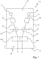
- FIG 1 a plan view of a motor vehicle headlight 10 with a horizontally cut housing 12, the light exit opening is covered by a transparent cover plate 14.
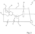
- figure 2 shows the headlight from the figure 1 in a side cut.
- An exemplary embodiment of a light module 16 according to the invention is arranged in the interior of the housing 12 .
- the light module 16 has a first semiconductor light source 18 and a first primary optics 20 which bundles light 22 from the first semiconductor light source 18 into a first focal region 24 .
- the light module 16 also has a second semiconductor light source 26 and a second primary optics 28 which bundles light 30 from the second semiconductor light source 26 into a second focal region 32 .
- a refractive secondary optics 36 arranged in the luminous flux downstream of the diaphragm 34 collects light emanating from the focal regions of the first semiconductor light source and the second semiconductor light source and directs this light in an area in front of the light module 16 and the motor vehicle headlight 10, for example to illuminate a roadway.
- the second focal area 32 differs from the first focal area 24 .
- Both focal areas 24, 32 are preferably next to each other, and they can overlap.
- the spatial dimensions of both focal areas 24, 32 can be identical.
- the refractive secondary optics 36 is a one-piece cohesive solid and has a first partial volume 36 . This beam path is a first low beam beam path.
- the secondary optics 36 also has a second partial volume 36.7, which lies in the beam path of light 30 from the second semiconductor light source 26, which emanates from the second focal region 32. This beam path is a second low beam beam path.
- a light entry surface of the first partial volume 36.6 has a shape that bundles the first low-beam light beam path more strongly in a horizontal direction when the light module 16 is used as intended than in a vertical direction when it is used as intended.
- a light exit surface of the secondary optics 36 for both partial volumes 36.6, 36.7 has a shape that bundles the light 22 exiting the light exit surface from the first semiconductor light source 18 and light 30 from the second semiconductor light source 26 more strongly in the vertical direction than in the horizontal direction when used as intended.
- the light entry surface of the second partial volume 36.7 is designed in such a way that the second partial volume 36.7 as a whole bundles the light from the second semiconductor light source 26 less strongly in the horizontal direction than in the vertical direction.
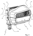
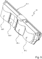
- figure 3 shows an advantageous embodiment of a light module 16 according to the invention, which is able to produce several different light distributions.
- a heat sink 38 which has a plurality of cooling ribs in the form of representation shown.
- the heat sink 38 is mechanically connected to a holding frame 40 .
- the optical components required for generating light distributions, such as light sources and primary optics, and secondary optics 36 are fastened to the holding frame 40 and/or the heat sink 38 .
- the light module 16 has a signal light component from which in the figure 1 a transparent lens 42 having scattering structures can be seen.
- the light module 16 has a combination of a low beam module and a high beam module, of which combination in the figure 1 the refractive secondary optics 36 is visible.
- Other parts of the signal light component and the combination of a low beam module and a high beam module are in the figure 1 covered by opaque covers 44.
- a bracket 46 for the mechanical headlight range control is attached to the holding frame 40 of the light module 16 .
- An axis of rotation 50 of a headlamp leveling system is defined by a suspension 48 fastened laterally, for example, to the holding frame 40 .
- An actuator acts on the boom 46 from below and pivots the boom 46 and thus the entire light module 16 in the plane perpendicular to the axis of rotation 50 .
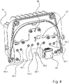
- FIG. 4 shows the cooling body 38 from FIG figure 3 together with a circuit board 52 attached thereto.
- Circuit board 52 has first low-beam semiconductor light sources 18.1, 18.2 for a first low-beam beam path, second low-beam semiconductor light sources 26.1, 26.2 for a second low-beam beam path, first high-beam semiconductor light sources 54.1, 54.2 for a first high-beam beam path, second high-beam light -Semiconductor light sources 56.1, 56.2 for a second high beam path, and a signal light semiconductor light source 58.
- the semiconductor light sources preferably have a square light exit surface.
- the low-beam semiconductor light sources 18.1, 18.2 of the first low-beam light beam path are arranged rotated relative to the low-beam semiconductor light sources 26.1, 26.2 of the second low-beam light beam path.
- the low-beam semiconductor light sources and the high-beam semiconductor light sources are arranged next to one another, with the low-beam semiconductor light sources 18.1, 18.2, 26.1, 26.2 being arranged centrally and the high-beam semiconductor light sources 54.1, 54.2 of the first high-beam beam path on the outside next to the low-beam semiconductor light sources 18.1, 18.2 of the first low beam path are arranged and the high beam semiconductor light sources 56.1, 56.2 of the second high beam path are arranged laterally outside next to the low beam semiconductor light sources 26.1, 26.2 of the second low beam path.
- the high beam semiconductor light sources are all at a first level and the low beam semiconductor light sources are all at a second level. The second level is above the first level.
- the semiconductor light source 58 for the signal light is centrally arranged above the low beam semiconductor light sources and the high beam semiconductor light sources.
- a connector 60 is arranged on circuit board 52 below the semiconductor light sources, which plug serves as an interface for supplying energy to the semiconductor light sources mounted on circuit board 52 and for controlling the semiconductor light sources by a light control device.
- FIG 5 shows the subject of figure 4 after mounting an attachment optics combination 62.
- the attachment optics combination 62 consists of an attachment optics 64 for the signal light semiconductor light source and one primary optics 20.1, 20.2, 28.1, 28.2 for each low beam semiconductor light source and one primary optics 64.1, 64.2, 66.1, 66.2 for each high beam -Semiconductor light source.
- the front optics 64 are arranged in front of the signal light semiconductor light source 58 . In each case one primary optics is arranged in front of one low-beam semiconductor light source and one high-beam semiconductor light source.
- the attachment optics combination 62 is preferably a one-piece plastic injection molded part.
- the signal light attachment optics 64 is a Fresnel lens in the illustrated embodiment.
- the low beam and High beam primary optics 20.1, 20.2, 28.1, 28.2, 64.1, 64.2, 66.1, 66.2 are catadioptric primary optics in the embodiment shown. They are preferably, together with the signal light attachment optics 64, components of the one-piece cohesive attachment optics combination 62 made of transparent plastic.
- the figure 6 shows the subject of Figures 3 to 5 together with an aperture combination 68, the structured lens 42 for the signal light, the secondary optics 36 and a secondary optics holder 37, which is used to attach the secondary optics 36 to the rest of the light module and which also has no optical function.
- the diaphragm combination 68 serves as a diaphragm for the low beam distribution and is located between the front lens combination 62 on the one hand and the secondary lens 36 on the other side.
- the diaphragm combination 68 is a mirror diaphragm which has a reflecting diaphragm surface. The reflective panel surface protrudes into the low beam beam path.
- the diaphragm combination 68 is arranged in such a way that its diaphragm edge facing the secondary optics 36 is illuminated by all low-beam semiconductor light sources.
- the reflecting screen surface preferably encloses an acute angle, that is to say an angle which is less than 90°, with the light rays which are incident from the primary optics of the low beam and impinge on the reflecting screen surface. At least most of the is preferred reflective panel surface is aligned horizontally when the light module 16 is used as intended, or has only an angle of inclination to the horizontal that is less than 30°.
- the reflecting surface of the screen reflects the incident light back into the low beam beam path, which contributes to the good optical efficiency of the light module.
- the optical efficiency is the proportion of the light generated by the low beam semiconductor light sources that ultimately contributes to the generation of the desired light distribution in front of the light module.
- the panel combination 68 has a first panel half 68.1 and a second panel half 68.2.
- the first screen half 68.1 has a step 68.3.
- the step 68.3 consists of three sub-areas, which in each case border one another in pairs and of which the two outer sub-areas are arranged offset in relation to one another in the vertical direction when the light module is used as intended.
- the step is arranged in such a way that a surface normal of the inner partial surface located between the two outer partial surfaces is transverse to the main emission direction 70 of the light module.
- the step 68.3 is arranged in such a way that it protrudes into the beam path of the first low beam beam path.
- This step 68.3 is used to generate a step in the light-dark boundary of an asymmetrical low beam distribution.
- the the level 68.3 exhibiting (first) low-beam beam path is a low-beam beam path that bundles the light strongly.
- the other low-beam beam path is the second low-beam beam path, which bundles the light less and distributes it more widely.
- the second diaphragm half projecting into this second low beam beam path preferably has no step.
- an embodiment in the form of a one-piece screen combination 68 is preferred.
- the diaphragm combination 68 is only narrow along the main light propagation direction of the light in the low beam beam paths (e.g. like the narrow side of a metal sheet that is e.g. less than 1 mm thick), so that the step 68.3 is only part of a contoured one edge of a thin metal sheet.
- the diaphragm can also extend in the vertical direction, starting from the optically effective diaphragm edge.
- the optically effective edge of the screen which is imaged as the light-dark boundary of the low beam distribution in the area in front of the light module, is then an upper edge of the screen.
- the figure 6 shows in particular a preferred configuration of the light exit surface 36.1 of the secondary optics 36 as a generally cylindrical-convex light exit surface, with an axis 71 of the cylinder extending transversely to the main emission direction 70 of the Light module 16 extends.
- the main direction of emission 70 coincides with the straight-ahead direction of travel of the motor vehicle and lies parallel to an imaginary line in the figure 4 runs through the center points of the high beam semiconductor light sources 54.1, 54.2, 56.1, 56.2 and parallel to another imaginary line that runs through the center points of the low beam semiconductor light sources 18.1, 18.2, 26.1, 26.2.
- the cross-sectional shape of the refractive secondary optics 36 does not change.
- An exception applies at most to the left and right end of the light exit surface 36.1, which, however, each extends over less than 5% of the length of the light exit surface 36.1 in the direction of the cylinder axis.
- figure 7 shows parts of the light module 16 in a plan view.
- the light from the associated semiconductor light sources exiting from the second pair of primary optics 20.1, 20.2, viewed from the left runs in a first low-beam light beam path
- the light from the associated semiconductor light sources, exiting from the third pair of primary optics 28.1, 28.2, viewed from the left runs in a second low beam beam path.
- a first high beam path runs to the left of the two low beam beam paths
- a second high beam path runs to the right of the two low beam beam paths.
- figure 7 also shows that the light entry surfaces of the refractive secondary optics 36 in a plane in which the Cylinder axis 71 and the main emission direction 70 of the light module 16 are, have different shapes.
- the secondary optics has a separate light entry surface for each low-beam beam path and each high-beam beam path.
- the light entry surface 36.2 is a light entry surface of the first high beam path.
- the light entry surface 36.3 is a light entry surface of the first low-beam light beam path and delimits an imaging partial volume 36.6 of the refractive secondary optics 36.
- the light entry surface 36.4 is a light entry surface of the second low-beam light beam path and delimits a horizontally fanning and vertically focusing partial volume (36.7) of the light-refracting secondary optics.
- the light entry surface 36.5 is a light entry surface of the second high beam path. The individual light entry surfaces are next to each other in the same order as the associated pairs of primary optics.
- figure 8 shows the secondary optics from the figure 7 with a view of the four light entry surfaces 36.2, 36.3, 36.4, 36.5 of the four beam paths.
- the refractive secondary optics 36 is a one-piece component.
- the shape of the two light entry surfaces 36.2, 36.5 of the partial volume of the refractive secondary optics of the high beam path and the light entry surface 36.3 of the partial volume of the refractive secondary optic of the first low beam path are convex in the plane mentioned, in which the cylinder axis 71 and the main emission direction 70 of the light module 16 lie, while the shape of the light entry surface 36.4 of the partial volume of the refractive secondary optics of the second Low beam beam path is concave in said plane.
- a low-beam light distribution is generated by superimposing light propagating in at least two low-beam light beam paths, with a first low-beam light path having an imaging partial volume of refractive secondary optics, while a second low-beam light path has a partial volume of refractive secondary optics, which scatters light in the horizontal plane and focuses it in the vertical plane .
- the two low beam beam paths are arranged next to each other directly adjacent (i.e.
- the bundle cross section of the light propagating in the respective beam path can be and is also limited by the one-piece diaphragm combination, with the protruding into the respective beam paths
- Surfaces of the panel combination are offset from each other in the vertical direction only by the height of a stage that is projected as a stage of an asymmetric low beam distribution in a front of the light module.
- the panel combination can be produced easily and with low tolerances with regard to the height offset relative to one another.
- the number of low beam or high beam beam paths can be increased by adding beam paths horizontally or by placing beam paths one on top of the other. Through the measures described, the number of Parts that make up the light module 16 are reduced. This makes the system simpler and cheaper.
- the one-piece realization of the secondary optics has the advantage over a separate realization of a light entry lens combination and a cylindrical lens that an exact positioning of such a lens combination to the cylindrical lens, be it through precisely manufactured holders or adjustment, is not necessary.
- figure 9 shows a top view of the beam paths of the two low beam beam paths 72 and 74 in the example shown.
- a first low beam beam path 72 is generated with the following elements: two low beam semiconductor light sources 18.1, 18.2, two catadioptric primary optics 20.1, 20.2 for bundling the light of the low beam semiconductor light sources 18.1, 18.2, a mirrored diaphragm combination 68 protruding into the focal area of the two primary optics 20.1, 20.2 with stage 68.3 and a projection lens, which is a partial volume 36.6 of a refractive secondary optics 36.
- the light entry surface of this partial volume 36.6 bundles the light more strongly in the horizontal plane than in the vertical plane.
- the light exit surface 36.1 has the cylindrical shape described and thus bundles the light less strongly in horizontal planes than in the vertical planes.
- the second low beam beam path 74 is with the following Elements generated: Two low beam semiconductor light sources 26.1,26.2, two catadioptric primary optics 28.1, 28.2 for bundling the light of the low beam semiconductor light sources 26.1,26.2, one projecting into the focal area of the two primary optics 28.1, 28.2 mirrored diaphragm half 68.2 without step, a lens that a further sub-volume 36.7 of a refractive secondary optics 36 is.
- the light entry surface 36.4 of this further partial volume 36.7 is preferably a concave free-form surface.
- the light exit surface 36.1 has the cylindrical shape described and thus bundles the light less strongly in horizontal planes than in the vertical planes.
- the light entry surface 36.4 is thus designed in such a way that the associated further partial volume 36.7 of the refractive secondary optics 36 bundles the light less in the horizontal plane than in the vertical plane.
- this further partial volume 36.7 acts as a diverging lens, while in the vertical plane it acts as a convergent lens with the same image point as the partial volume 36.6 of the first low-beam light beam path 72.
- the catadioptric primary optics of the low beam beam paths i.e. the primary optics 20.1, 20.2, 28.1, 28.2 in the exemplary embodiment described, are designed in such a way that they bundle and deflect the light from the semiconductor light sources, so that the light from the semiconductor light sources emanating from these primary optics falls obliquely from above onto the front edge of the screen falls and focuses in the vicinity of the aperture edge, i.e. in a focal area of the primary optics becomes.
- a light distribution inside the light module with a light-dark boundary is created in the plane of the cover edge. The exact shape of this light-dark boundary is determined by the shape of the aperture edge.
- a diaphragm half 68.1 of diaphragm combination 68 that protrudes into the first focal region, i.e. into the focal region of the first low-beam light beam path, is provided with a step 68.3, in order in this way to create a step in the course of the light-dark boundary of the to generate the external low beam distribution resulting from the light module.
- This screen half 68.1 is in the first low beam path 72.
- the other screen half 68.2 of the screen combination 68 is in the second low beam path 74 and has no step. In this way, the second low-beam beam path 74 produces a straight, horizontally running external light-dark boundary.
- the refractive secondary optics 36 are designed in such a way that they image the internal light distribution, which is generated in the plane of the aperture edge with step 68.3, onto the road. Since the light entry surface 36.3 of the partial volume 36.6 of the refractive secondary optics 36, which belongs to the first low-beam light beam path 72, bundles the light horizontally more than vertically and the light exit surface of this partial volume bundles the light vertically more than horizontally, resulting in a distorted image, i.e. the vertical and horizontal image scales are the same Not same.
- the associated diaphragm half 68.2 of the diaphragm combination 68 which has no step, is illuminated in the second low-beam light beam path 74.
- the associated light entry surface 36.4 of the refractive secondary optics 36 is concave and focuses the light more weakly than the corresponding light entry surface 36.3 of the first low-beam light beam path 72.
- the light rays exiting in the second low-beam light beam path 74 from the refractive secondary optics 36 have a horizontally broader directional distribution than the light beams exiting in the first low beam beam path 72 from the refractive secondary optics 36 .
- This fanning out of the beams in the horizontal plane increases the width of the low beam light distribution.
- the distribution of the light and the width of the light distribution can be controlled by shaping the free-form surface serving as the light entry surface 36.4.
- figure 10 shows a plan view of the second low-beam light beam path 74. It can be seen that due to the weaker bundling in the horizontal plane, the light cone is wider on the cylindrical light exit surface 36.1 of the refractive secondary optics than on the associated light entry surface.
- the width of the first Dipped light beam path 72 when the light exits the refractive secondary optics 36 is approximately the same size as when it enters the refractive secondary optics 36. It makes sense not to realize the second low beam path 74 as an external beam path.
- the second low beam path 74 lies between the adjacent first low beam path 72 and the adjacent second high beam path. Due to this position between two adjacent beam paths, a wide area of the light exit surface 36.1 of the refractive secondary optics 36 can be used to generate the widely distributed low beam component. The function of the adjacent beam paths is not disturbed by this. As a desirable result, the horizontal width of the light module 16 can be kept small.
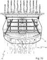
- FIG 11 shows a top view of the high beam paths 76, 78.
- Each high beam path consists of the following elements: two high beam semiconductor light sources, two primary optics for bundling the light of the two high beam semiconductor light sources, a projection lens, which is a partial volume of a refractive secondary optics.
- Each light entry surface of a partial volume bundles the light more strongly in the horizontal plane than in the vertical plane.
- the cylindrical light exit surface bundles the light more strongly in the vertical plane than in the horizontal plane.
- figure 12 shows a plan view of the two low beam beam paths 72, 74 and the two High beam beam paths 76, 78 in comparison.
- the focal lengths of the primary optics of the low beam and the high beam are the same in the embodiment described.
- the focal point of the primary optics for the low beam paths is approximately on the front edge of the diaphragm combination 68, the focal point of the primary optics for the high beam paths is approximately in the same plane.
- the focal lengths can also be designed differently, which makes the system very flexible in design.
- the overall magnification of the optical system for the high-beam beam paths 76, 78 can be designed differently than for the low-beam light beam paths 72, 74. This can be advantageous, since different requirements are placed on the low-beam and high-beam distributions with regard to width, height and maximum illuminance.
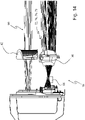
- figure 13 shows a plan view of a signal light beam path 80.
- the light from the signal light semiconductor light source 58 is bundled by the Fresnel lens 64 and directed onto the structured light pane 42.
- FIG. Prism-shaped structures on the structured lens 42 further bundle the light and distribute it in the desired angular range of a signal light or position light distribution.
- having each prism illuminate approximately the same angular range results in a bright and uniform appearance of the entire structured lens 42.
- figure 14 shows the beam paths 72, 74, 76, 78, 80 of all Light functions of the light module 16 functions in a side view and figure 15 shows the beam paths 72, 74, 76, 78, 80 of all functions in an oblique view.
- the low-beam semiconductor light sources can be switched and/or dimmed separately. This allows different light distributions to be generated, e.g. a wide city light with a large luminous flux of the second low beam path when the luminous flux of the first low beam path is not so high, or a motorway light with a large luminous flux of the first low beam beam path with a not so high luminous flux of the second low beam.
- the number of low beam or high beam beam paths can be increased by adding beam paths horizontally or by placing beam paths one on top of the other.
- the refractive secondary optics simply have to be extended horizontally.
- an additional refractive secondary optic is required for each additional level.
- the signal light beam path can alternatively or additionally be used as a beam path for a flashing light. It is advantageous to use semiconductor light sources that glow yellow for this purpose, particularly if the beam path is to be used in parallel for signal light. However, it is also possible to use semiconductor light sources emitting white light and to color the front optics and/or the structured pane yellow.
- the main beam beam paths can also be used for the daytime running light function. To do this, they are dimmed and switched on together with the daytime running (signal) light source, which illuminates both the surface of the structured lens and the associated surface of the refractive secondary optics.
- the light module according to the invention can be used as a cornering light module because the light module is mounted such that it can rotate about a vertical axis and can be rotated in a controlled manner via a suitable actuator.
- the semiconductor light sources are preferably light-emitting diodes.
- a laser light source can also be used as the light source in conjunction with a phosphor platelet that is illuminated by the laser and thereby excited. This applies both to a subset of the light sources and to all light sources of the light module. As a result, the luminance of the light source and thus the maximum illuminance can be increased if necessary.
- the light module does not have any components serving to generate a signal light light distribution.
- the light module is a bi-functional light module that can be used to generate low beam and high beam distributions.
- the catadioptric primary optics can be implemented in whole or in part as concave mirror reflectors which, for example, have a metallic-reflecting coating and delimit a reflection volume filled with air.
- the circuit board plane is approximately horizontal and the semiconductor light sources arranged thereon radiate upwards, preferably vertically upwards, into the reflectors in order to direct their light in the direction of travel into the various intermediate image planes or focal areas.
- the catadioptric primary optics can also be replaced in whole or in part by lenses or lens systems. Furthermore, it is also possible to replace the catadioptric primary optics in whole or in part with light guide optics.
Description
- Die vorliegende Anmeldung betrifft ein Lichtmodul für einen Kraftfahrzeugscheinwerfer nach dem Oberbegriff des Anspruchs 1.
- Ein solches Lichtmodul ist aus der
EP 3 163 155 A1 bekannt. DieUS 8,733,992 B1 zeigt einen Nebelscheinwerfer. Aus derWO 2015/058227 A1 ist ein Mikroprojektoren aufweisendes Lichtmodul für Kraftfahrzeugscheinwerfer bekannt. Aus dem abstract derJP-2017-084581 A - Ortsangaben wie oben und unten beziehen sich in dieser Anmeldung immer auf eine Ausrichtung des Lichtmoduls, die seiner Ausrichtung bei bestimmungsgemäßer Verwendung in einem Kraftfahrzeug entspricht.
- Die
US 6,948,836 B2 offenbart ein Abblendlicht-Modul, welches durch eine ungefähr horizontal liegende verspiegelte Blende eine Hell-Dunkel-Grenze erzeugt. Das zur Erzeugung einer Abblendlichtverteilung dienende Licht wird durch eine Halbleiterlichtquelle erzeugt und durch einen Reflektor gebündelt. Das gebündelte Licht wird von oben auf die vordere Blendenkante gerichtet. Ein Bild der Blendenkante wird durch eine als Projektionslinse realisierte Lichtauskoppeloptik als Hell-Dunkel-Grenze einer Abblendlichtverteilung auf die Straße projiziert. - Aus der
DE 10 2008 036 192 A1 ist ein LED-Bi-Funktionsmodul zur Erzeugung einer Abblendlicht- und Fernlichtverteilung eines KFZ-Scheinwerfers bekannt. Eine horizontal liegende Blende ist hier dünn ausgeführt und wird für die Erzeugung des Fernlichtanteils zusätzlich von unten beleuchtet. Für die Kollimierung des LED-Lichts werden Reflektoren oder katadioptrische Optiken verwendet. - Aus der
DE 10 2014 226 650 A1 ist eine Beleuchtungseinrichtung für Kraftfahrzeuge bekannt, die mindestens drei Lichtfunktionen wie z.B. Abblendlicht, Fernlicht, Tagfahrlicht und/oder Positionslicht realisiert. Dabei wird das Abblendlicht analog zu der Beschreibung in derUS 6,948,836 B2 und das Fernlicht und Tagfahrlicht auf ähnliche Art und Weise wie in derDE 10 2008 036 192 A1 erzeugt. - Ein als per se bekannt vorausgesetztes Lichtmodul weist eine erste Halbleiterlichtquelle und eine erste Primäroptik auf, die Licht der ersten Halbleiterlichtquelle in einen ersten Fokalbereich bündelt. Das bekannte Lichtmodul weist weiter eine zweite Halbleiterlichtquelle und eine zweite Primäroptik auf, die Licht der zweiten Halbleiterlichtquelle in einen zweiten Fokalbereich bündelt. Das bekannte Lichtmodul weist weiter eine in den ersten Fokalbereich und in den zweiten Fokalbereich hineinragende und von einer Blendenkante begrenzte Blendenkombination und eine lichtbrechende Sekundäroptik auf, die von den Fokalbereichen ausgehendes Licht der ersten Halbleiterlichtquelle und der zweiten Halbleiterlichtquelle sammelt und in ein Vorfeld des Lichtmoduls richtet und damit zum Beispiel eine vor einem Kraftfahrzeug liegende Fahrbahn ausleuchtet.
- Ausgehend von einem diese Merkmale aufweisenden Stand der Technik besteht die Aufgabe der Erfindung darin, ein möglichst kompaktes Lichtmodul zu konstruieren, mit dem wenigstens eine Abblendlichtverteilung erzeugt werden kann und das möglichst einfach ausgeführt ist und mit minimalem Herstellungs-und/oder Einstellungsaufwand seiner optischen Elemente herstellbar ist.
- Diese Aufgabe wird mit den Merkmalen des Anspruchs 1 gelöst. Dabei unterscheidet sich das erfindungsgemäße Lichtmodul von dem eingangs genannten Stand der Technik nach der
EP 3 163 155 A1 durch seine kennzeichnenden Merkmale. - Dadurch, dass der zweite Fokalbereich von dem ersten Fokalbereich verschieden ist, und dass die Sekundäroptik ein erstes Teilvolumen aufweist, das im Strahlengang von Licht der ersten Halbleiterlichtquelle liegt, das von dem ersten Fokalbereich ausgeht, und ein zweites Teilvolumen aufweist, das im Strahlengang von Licht der zweiten Halbleiterlichtquelle liegt, das vom zweiten Fokalbereich ausgeht, ergeben sich ein erster Abblendlichtstrahlengang, der die erste Halbleiterlichtquelle, die erste Primäroptik und das erste Teilvolumen aufweist, und ein zweiter Abblendlichtstrahlengang, der die zweite Halbleiterlichtquelle, die zweite Primäroptik und das zweite Teilvolumen aufweist. Durch die beiden Abblendlichtstrahlengänge ergeben sich mehr Möglichkeiten der Optimierung der von dem Lichtmodul insgesamt erzeugten Lichtverteilungen als bei nur einem Abblendlichtstrahlengang.
- Indem die Abblendlichtstrahlengänge zum Beispiel separat einschaltbar und ausschaltbar oder dimmbar sind, können durch verschiedene Kombinationen unterschiedliche Lichtverteilungen erzeugt werden, z.B. Stadtlicht oder Autobahnlicht. Stadtlicht zeichnet sich durch eine vergleichsweise breite Lichtverteilung mit vergleichsweise kleiner Reichweite aus, während sich Autobahnlicht durch eine vergleichsweise schmale Lichtverteilung und eine vergleichsweise große Reichweite auszeichnet.
- Dadurch, dass das Lichtmodul eine einstückige, lichtbrechende Sekundäroptik aufweist, wird eine vorgegebene, geforderte Genauigkeit der Positionierung der beiden Teilvolumina der Sekundäroptik zueinander und in Beziehung zu den Fokalbereichen der Primäroptiken mit einer geringeren Fertigungspräzision der beteiligten Bauteile und/oder einem verringerten Justierungsaufwand erreicht als bei einer Verwendung von mehrteiligen Sekundäroptiken.
- Dadurch, dass eine Lichteintrittsfläche des ersten Teilvolumens eine Form besitzt, die den ersten Strahlengang in einer bei bestimmungsgemäßer Verwendung des Lichtmoduls horizontalen Richtung stärker bündelt als in einer bei dem bestimmungsgemäßen Gebrauch vertikalen Richtung, wird das in dem zugehörigen ersten Strahlengang propagierende Licht auf einen in horizontaler Richtung vergleichsweise schmalen Bereich konzentriert, so dass sich dort eine vergleichsweise große Helligkeit und Reichweite ergibt.
- Dadurch, dass eine Lichtaustrittsfläche der Sekundäroptik für beide Teilvolumina eine Form besitzt, die das aus der Lichtaustrittsfläche austretende Licht der ersten Halbleiterlichtquelle und der zweiten Halbleiterlichtquelle bei der bestimmungsgemäßen Verwendung in vertikaler Richtung stärker bündelt als in horizontaler Richtung, wird ein für beide Teilvolumina ähnlicher Helligkeitsverlauf in vertikaler Richtung erzeugt.
- Dadurch, dass die Lichteintrittsfläche des zweiten Teilvolumens so gestaltet ist, dass das zweite Teilvolumen insgesamt das Licht der zweiten Halbleiterlichtquelle in horizontaler Richtung weniger stark bündelt als in vertikaler Richtung, wird ein in horizontaler Richtung breiter Lichtanteil einer Abblendlichtverteilung erzeugt.
- Eine bevorzugte Ausgestaltung zeichnet sich dadurch aus, dass die Lichtaustrittsfläche der Sekundäroptik eine allgemein zylinderförmig-konvexe Lichtaustrittsfläche ist, wobei sich die Achse des Zylinders quer zu der Hauptabstrahlrichtung des Lichtmoduls erstreckt.
- Bevorzugt ist auch, dass das Lichtmodul eine Kombination aus einem Abblendlichtmodul und einem Fernlichtmodul aufweist.
- Weiter ist bevorzugt, dass das Lichtmodul dazu eingerichtet ist, wenigstens zwei Abblendlichtstrahlengänge und wenigstens zwei Fernlichtstrahlengänge zu erzeugen.
- Eine weitere bevorzugte Ausgestaltung zeichnet sich dadurch aus, dass die beiden Abblendlichtstrahlengänge einander benachbart zwischen den beiden Fernlichtstrahlengängen verlaufen.
- Bevorzugt ist auch, dass die Sekundäroptik für jeden Abblendlichtstrahlengang und für jeden Fernlichtstrahlengang eine separate Lichteintrittsfläche aufweist.
- Weiter ist bevorzugt, dass ein erster Abblendlichtstrahlengang mit folgenden Elementen erzeugt wird: zwei Abblendlicht-Halbleiterlichtquellen, zwei katadioptrischen Primäroptiken zur Bündelung des Lichts der Abblendlicht-Halbleiterlichtquellen, einer in den Fokalbereich der beiden Primäroptiken ragenden verspiegelten Blendenkombination, die eine Stufe aufweist, und mit einer Projektionslinse, die ein Teilvolumen der lichtbrechenden Sekundäroptik ist.
- Eine weitere bevorzugte Ausgestaltung zeichnet sich dadurch aus, dass eine Lichteintrittsfläche dieses Teilvolumens dazu eingerichtet ist, das Licht in einer bei bestimmungsgemäßer Verwendung des Lichtmoduls horizontalen Ebene stärker zu bündeln als in einer vertikalen Ebene.
- Bevorzugt ist auch, dass der zweite Abblendlichtstrahlengang mit folgenden Elementen erzeugt wird: zwei Abblendlicht-Halbleiterlichtquellen, zwei katadioptrischen Primäroptiken zur Bündelung des Lichts der Abblendlicht-Halbleiterlichtquellen, einer in den Fokalbereich der beiden Primäroptiken ragenden verspiegelten Blendenhälfte, die keine Stufe aufweist, und mit einer Linse, die ein weiteres Teilvolumen der lichtbrechenden Sekundäroptik ist.
- Weiter ist bevorzugt, dass die Lichteintrittsfläche des weiteren Teilvolumens eine konkave Freiformfläche ist.
- Eine weitere bevorzugte Ausgestaltung zeichnet sich dadurch aus, dass Abblendlicht- und Fernlicht-Primäroptiken katadioptrische Primäroptiken sind.
- Bevorzugt ist auch, dass das Lichtmodul ein Signallichtmodul, beispielsweise ein Tagfahrlicht-und/oder ein Positionslicht- und/oder ein Blinklichtmodul aufweist.
- Weiter ist bevorzugt, dass die katadioptrischen Abblendlicht- und Fernlicht-Primäroptiken zusammen mit einer Signallicht-Vorsatzoptik Bestandteile einer einstückig-stoffschlüssig zusammenhängenden Vorsatzoptikkombination aus transparentem Kunststoff sind.
- Bevorzugt ist auch, dass die Signallicht-Vorsatzoptik eine Fresnel-Linse ist.
- Weitere Vorteile ergeben sich aus der nachfolgenden Beschreibung, den Zeichnungen und den Unteransprüchen. Es versteht sich, dass die vorstehend genannten und die nachstehend noch zu erläuternden Merkmale nicht nur in der jeweils angegebenen Kombination, sondern auch in anderen Kombinationen oder in Alleinstellung verwendbar sind, ohne den Rahmen der vorliegenden Erfindung zu verlassen.
- Ausführungsbeispiele der Erfindung sind in den Zeichnungen dargestellt und werden in der nachfolgenden Beschreibung näher erläutert.
- Dabei zeigen, jeweils in schematischer Form:
- Figur 1
- eine Draufsicht auf ein Ausführungsbeispiel eines Kraftfahrzeugscheinwerfers;
- Figur 2
- eine Seitenansicht des Kraftfahrzeugscheinwerfers aus der
Figur 1 ; - Figur 3
- eine Schrägansicht eines Ausführungsbeispiel eines erfindungsgemäßen Lichtmoduls;
- Figur 4
- eine Schrägansicht eines Kühlkörpers mit einer Platine des Lichtmoduls aus
Figur 3 ; - Figur 5
- eine Schrägansicht von Bestandteilen des Lichtmoduls der
Figur 4 zusammen mit einer Vorsatzoptikkombination; - Figur 6
- eine Schrägansicht der Bestandteile des Lichtmoduls der
Figur 5 zusammen mit weiteren Bestandteilen eines Lichtmoduls; - Figur 7
- eine Draufsicht auf Bestandteile des Lichtmoduls der
Figur 6 - Figur 8
- eine Schrägansicht einer lichtbrechenden Sekundäroptik eines erfindungsgemäßen Lichtmoduls;
- Figur 9
- eine Draufsicht auf Bestandteile eines erfindungsgemäßen Lichtmoduls mit zwei Abblendlichtstrahlengängen;
- Figur 10
- eine Draufsicht auf Bestandteile eines erfindungsgemäßen Lichtmoduls mit einem zweiten Abblendlichtstrahlengang;
- Figur 11
- eine Draufsicht auf Bestandteile eines erfindungsgemäßen Lichtmoduls mit zwei Fernlichtstrahlengängen;
- Figur 12
- eine Draufsicht auf Bestandteile eines erfindungsgemäßen Lichtmoduls mit zwei Abblendlichtstrahlengängen und zwei Fernlichtstrahlengängen;
- Figur 13
- eine Draufsicht auf Bestandteile eines erfindungsgemäßen Lichtmoduls mit einem Signallichtstrahlengang;
- Figur 14
- eine Seitenansicht von Bestandteilen eines erfindungsgemäßen Lichtmoduls mit Abblendlichtstrahlengängen und/oder Fernlichtstrahlengängen und einem Signallichtstrahlengang; und
- Figur 15
- eine Schrägansicht von Bestandteilen eines erfindungsgemäßen Lichtmoduls mit Abblendlichtstrahlengängen, Fernlichtstrahlengängen und einem Signallichtstrahlengang.
- Dabei bezeichnen gleiche Bezugszeichen in verschiedenen Figuren jeweils gleiche oder zumindest ihrer Funktion nach vergleichbare Elemente.
- Im Einzelnen zeigt die
Figur 1 eine Draufsicht auf einen Kraftfahrzeugscheinwerfer 10 mit einem horizontal aufgeschnittenen Gehäuse 12, dessen Lichtaustrittsöffnung durch eine transparente Abdeckscheibe 14 abgedeckt wird.Figur 2 zeigt den Scheinwerfer aus derFigur 1 in einem seitlichen Schnitt. Im Inneren des Gehäuses 12 ist ein Ausführungsbeispiel eines erfindungsgemäßen Lichtmoduls 16 angeordnet. Das Lichtmodul 16 weist eine erste Halbleiterlichtquelle 18 und eine erste Primäroptik 20 auf, die Licht 22 der ersten Halbleiterlichtquelle 18 in einen ersten Fokalbereich 24 bündelt. Das Lichtmodul 16 weist weiter eine zweite Halbleiterlichtquelle 26 und eine zweite Primäroptik 28 auf, die Licht 30 der zweiten Halbleiterlichtquelle 26 in einen zweiten Fokalbereich 32 bündelt. Eine als Spiegelblende verwirklichte Blendenkombination 34 ragt in den ersten Fokalbereich 24 und in den zweiten Fokalbereich 32 hinein. Eine im Lichtstrom stromabwärts von der Blende 34 angeordnete lichtbrechende Sekundäroptik 36 sammelt von den Fokalbereichen ausgehendes Licht der ersten Halbleiterlichtquelle und der zweiten Halbleiterlichtquelle und richtet dieses Licht in ein Vorfeld des Lichtmoduls 16 und des Kraftfahrzeugscheinwerfers 10, um zum Beispiel eine Fahrbahn zu beleuchten. - Der zweite Fokalbereich 32 ist von dem ersten Fokalbereich 24 verschieden. Beide Fokalbereiche 24, 32 liegen bevorzugt nebeneinander, wobei sie sich überlappen können. Die räumlichen Abmessungen beider Fokalbereiche 24, 32 können identisch sein. Die lichtbrechende Sekundäroptik 36 ist ein einstückig-stoffschlüssig zusammenhängender Festkörper und weist ein erstes Teilvolumen 36.6 auf, das im Strahlengang von Licht 22 der ersten Halbleiterlichtquelle 18 liegt, das von dem ersten Fokalbereich 24 ausgeht. Dieser Strahlengang ist ein erster Abblendlichtstrahlengang. Die Sekundäroptik 36 weist weiter ein zweites Teilvolumen 36.7 auf, das im Strahlengang von Licht 30 der zweiten Halbleiterlichtquelle 26 liegt, das vom zweiten Fokalbereich 32 ausgeht. Dieser Strahlengang ist ein zweiter Abblendlichtstrahlengang.
- Erfindungsgemäß besitzt eine Lichteintrittsfläche des ersten Teilvolumens 36.6 eine Form, die den ersten Abblendlichtstrahlengang in einer bei bestimmungsgemäßer Verwendung des Lichtmoduls 16 horizontalen Richtung stärker bündelt als in einer bei dem bestimmungsgemäßen Gebrauch vertikalen Richtung. Dabei besitzt eine Lichtaustrittsfläche der Sekundäroptik 36 für beide Teilvolumina 36.6, 36.7 eine Form, die das aus der Lichtaustrittsfläche austretende Licht 22 der ersten Halbleiterlichtquelle 18 und Licht 30 der zweiten Halbleiterlichtquelle 26 bei bestimmungsgemäßer Verwendung in vertikaler Richtung stärker bündelt als in horizontaler Richtung. Die Lichteintrittsfläche des zweiten Teilvolumens 36.7 ist so gestaltet, dass das zweite Teilvolumen 36.7 insgesamt das Licht der zweiten Halbleiterlichtquelle 26 in horizontaler Richtung weniger stark bündelt als in vertikaler Richtung.
-
Figur 3 zeigt ein vorteilhaftes Ausführungsbeispiel eines erfindungsgemäßen Lichtmoduls 16, das in der Lage ist, mehrere verschiedene Lichtverteilungen zu erzeugen. - An der Rückseite des Lichtmoduls 16 befindet sich ein Kühlkörper 38, welcher in der gezeigten Darstellungsform mehrere Kühlrippen aufweist. Der Kühlkörper 38 ist mechanisch mit einem Halterahmen 40 verbunden. An dem Halterahmen 40 und/oder dem Kühlkörper 38 sind die zur Erzeugung von Lichtverteilungen erforderlichen optischen Komponenten wie Lichtquellen und Primäroptiken und eine Sekundäroptik 36 befestigt.
- Das Lichtmodul 16 weist eine Signallicht-Komponente auf, von der in der
Figur 1 eine Streustrukturen aufweisende, transparente Lichtscheibe 42 zu sehen ist. Darüber hinaus weist das Lichtmodul 16 eine Kombination aus einem Abblendlichtmodul und einem Fernlichtmodul auf, von welcher Kombination in derFigur 1 die lichtbrechende Sekundäroptik 36 sichtbar ist. Weitere Bestandteile der Signallicht-Komponente und der Kombination aus einem Abblendlichtmodul und einem Fernlichtmodul werden in derFigur 1 durch undurchsichtige Abdeckungen 44 verdeckt. - Weiterhin ist ein Ausleger 46 für die mechanische Leuchtweitenregelung an dem Halterahmen 40 des Lichtmoduls 16 befestigt. Durch eine zum Beispiel am Halterahmen 40 seitlich befestigte Aufhängung 48 wird eine Drehachse 50 einer Leuchtweitenregelung definiert. An dem Ausleger 46 greift unten ein nicht dargestellter Aktor an, der den Ausleger 46 und damit das ganze Lichtmodul 16 in der zur Drehachse 50 senkrechten Ebene verschwenkt.
-
Figur 4 zeigt den Kühlköper 38 aus derFigur 3 zusammen mit einer daran befestigten Platine 52. Die Platine 52 weist erste Abblendlicht-Halbleiterlichtquellen 18.1, 18.2 für einen ersten Abblendlichtstrahlengang, zweite Abblendlicht-Halbleiterlichtquellen 26.1, 26.2 für einen zweiten Abblendlichtstrahlengang, erste Fernlicht-Halbleiterlichtquellen 54.1, 54.2 für einen ersten Fernlichtstrahlengang, zweite Fernlicht-Halbleiterlichtquellen 56.1, 56.2 für einen zweiten Fernlichtstrahlengang, sowie eine Signallicht-Halbleiterlichtquelle 58 auf. - Die Halbleiterlichtquellen besitzen bevorzugt eine viereckige Lichtaustrittsfläche. Die Abblendlicht-Halbleiterlichtquellen 18.1, 18.2 des ersten Abblendlichtstrahlengangs sind gegenüber den Abblendlicht-Halbleiterlichtquellen 26.1, 26.2 des zweiten Abblendlichtstrahlengangs verdreht angeordnet. Die Abblendlicht-Halbleiterlichtquellen und die Fernlicht-Halbleiterlichtquellen sind nebeneinander angeordnet, wobei die Abblendlicht-Halbleiterlichtquellen 18.1, 18.2, 26.1, 26.2 zentral angeordnet sind und die Fernlicht-Halbleiterlichtquellen 54.1, 54.2 des ersten Fernlichtstrahlengangs seitlich außen neben den Abblendlicht-Halbleiterlichtquellen 18.1, 18.2 des ersten Abblendlichtstrahlengangs angeordnet sind und die Fernlicht-Halbleiterlichtquellen 56.1, 56.2 des zweiten Fernlichtstrahlengangs seitlich außen neben den Abblendlicht-Halbleiterlichtquellen 26.1, 26.2 des zweiten Abblendlichtstrahlengangs angeordnet sind. In der Höhe liegen die Fernlicht-Halbleiterlichtquellen alle auf einer ersten Höhe, und die Abblendlicht-Halbleiterlichtquellen liegen alle auf einer zweiten Höhe. Die zweite Höhe liegt oberhalb von der ersten Höhe. Die Halbleiterlichtquelle 58 für das Signallicht ist oberhalb der Abblendlicht-Halbleiterlichtquellen und der Fernlicht-Halbleiterlichtquellen zentral angeordnet.
- An der Platine 52 ist unterhalb der Halbleiterlichtquellen ein Stecker 60 angeordnet, der als Schnittstelle zur Energieversorgung der auf der Platine 52 angebrachten Halbleiterlichtquellen und zur Ansteuerung der Halbleiterlichtquellen durch ein Lichtsteuergerät dient.
-
Figur 5 zeigt den Gegenstand derFigur 4 nach der Montage einer Vorsatzoptikkombination 62. Die Vorsatzoptikkombination 62 besteht aus einer Vorsatzoptik 64 für die Signallicht-Halbleiterlichtquelle und jeweils einer Primäroptik 20.1, 20.2, 28.1, 28.2 für jede Abblendlicht-Halbleiterlichtquelle und jeweils einer Primäroptik 64.1, 64.2, 66.1, 66.2 für jede Fernlicht-Halbleiterlichtquelle. Die Vorsatzoptik 64 ist vor der Signallicht-Halbleiterlichtquelle 58 angeordnet. Jeweils eine Primäroptik ist vor je einer Abblendlicht-Halbleiterlichtquelle und jeweils einer Fernlicht-Halbleiterlichtquelle angeordnet. - Die Vorsatzoptikkombination 62 ist bevorzugt ein einstückiges Kunststoffspritzgussteil. Die Signallichtvorsatzoptik 64 ist im dargestellten Ausführungsbeispiel eine Fresnellinse. Die Abblendlichtund Fernlicht- Primäroptiken 20.1, 20.2, 28.1, 28.2 64.1, 64.2, 66.1, 66.2 sind in der dargestellten Ausgestaltung katadioptrische Primäroptiken. Sie sind bevorzugt zusammen mit der Signallicht-Vorsatzoptik 64 Bestandteile der einstückig-stoffschlüssig zusammenhängenden Vorsatzoptikkombination 62 aus transparentem Kunststoff.
- Die
Figur 6 zeigt den Gegenstand derFiguren 3 bis 5 zusammen mit einer Blendenkombination 68, der strukturierten Lichtscheibe 42 für das Signallicht, der Sekundäroptik 36 und einem Sekundäroptikhalter 37, der zur Befestigung der Sekundäroptik 36 am übrigen Lichtmodul dient und der darüber hinaus keine optische Funktion ausübt. - Die Blendenkombination 68 dient als Blende für die Abblendlichtverteilung und liegt zwischen der Vorsatzoptikkombination 62 auf der einen Seite und der Sekundäroptik 36 auf der anderen Seite. Die Blendenkombination 68 ist in der dargestellten Ausgestaltung eine Spiegelblende, die eine spiegelnde Blendenfläche besitzt. Die spiegelnde Blendenfläche ragt in den Abblendlichtstrahlengang hinein. Dabei ist die Blendenkombination 68 so angeordnet, dass ihre der Sekundäroptik 36 zugewandte Blendenkante von sämtlichen Abblendlicht-Halbleiterlichtquellen beleuchtet wird. Die spiegelnde Blendenfläche schließt mit von den Primäroptiken des Abblendlichtes her einfallenden Lichtstrahlen, die auf die spiegelnde Blendenfläche auftreffen, bevorzugt einen spitzen Winkel ein, also einen Winkel, der kleiner als 90° ist. Bevorzugt ist zumindest der größte Teil der spiegelnden Blendenfläche bei bestimmungsgemäßer Verwendung des Lichtmoduls 16 horizontal ausgerichtet oder weist nur einen Neigungswinkel zur Horizontalen auf, der kleiner als 30° ist. Durch die spiegelnde Blendenfläche wird dort einfallendes Licht in den Abblendlichtstrahlengang zurück reflektiert, was zu einer guten optischen Effizienz des Lichtmoduls beiträgt. Die optische Effizienz ist dabei der Anteil am von den Abblendlicht-Halbleiterlichtquellen erzeugten Licht, das letztlich zur Erzeugung der erwünschten Lichtverteilung im Vorfeld des Lichtmoduls beiträgt.
- Die Blendenkombination 68 weist eine erste Blendenhälfte 68.1 und eine zweite Blendenhälfte 68.2 auf. Die erste Blendenhälfte 68.1 weist eine Stufe 68.3 auf. Die Stufe 68.3 besteht aus drei Teilflächen, die jeweils paarweise aneinander grenzen und von denen die beiden äußeren Teilflächen bei einer bestimmungsgemäßen Verwendung des Lichtmoduls in vertikaler Richtung zueinander versetzt angeordnet sind. Die Stufe ist so angeordnet, dass eine Flächennormale der zwischen den beiden äußeren Teilflächen liegenden inneren Teilfläche quer zu der Hauptabstrahlrichtung 70 des Lichtmodules liegt.
- Eine der Sekundäroptik 36 zugewandte und von einer Blendenkante begrenzte Seite der Blendenkombination 68 ragt in die Fokalbereiche 24, 32 (vergleiche
Figur 1 ) der Abblendlichtstrahlengänge hinein. Dabei ist die Stufe 68.3 so angeordnet, dass sie in den Strahlengang des ersten Abblendlichtstrahlengangs hineinragt. Diese Stufe 68.3 dient zur Erzeugung einer Stufe in der Hell-Dunkel-Grenze einer asymmetrischen Abblendlichtverteilung. Der die Stufe 68.3 aufweisende (erste) Abblendlichtstrahlengang ist ein Abblendlichtstrahlengang, der das Licht stark bündelt. - Der andere Abblendlichtstrahlengang ist der zweite Abblendlichtstrahlengang, der das Licht weniger stark bündelt und eher breit verteilt. Die in diesen zweiten Abblendlichtstrahlengang ragende zweite Blendenhälfte weist bevorzugt keine Stufe auf. Prinzipiell ist es möglich, anstelle einer Blendenkombination 68 auch mehrere einzelne Blenden zu verwenden. Um die Anzahl der Bauteile des Lichtmoduls 16 zu verringern, ist eine Ausgestaltung in Form einer einstückigen Blendenkombination 68 bevorzugt.
- Weiter ist es prinzipiell auch möglich, dass die Blendenkombination 68 entlang der Hauptlichtausbreitungsrichtung des Lichtes in den Abblendlichtstrahlengängen nur schmal ist (z.B. wie die Schmalseite eines Bleches, das z.B. weniger als 1 mm dick ist), so dass die Stufe 68.3 nur ein Teil einer konturierten Kante eines dünnen Bleches ist. Die Blende kann sich in diesem Fall auch von der optisch wirksamen Blendenkante ausgehend in vertikaler Richtung erstrecken. Die optisch wirksame Blendenkante, die als Hell-Dunkel-Grenze der Abblendlichtverteilung in das Vorfeld des Lichtmoduls abgebildet wird, ist dann eine obere Kante der Blende.
- Die
Figur 6 zeigt insbesondere eine bevorzugte Ausgestaltung der Lichtaustrittsfläche 36.1 der Sekundäroptik 36 als allgemein zylinderförmig-konvexe Lichtaustrittsfläche, wobei sich eine Achse 71 des Zylinders quer zu der Hauptabstrahlrichtung 70 des Lichtmoduls 16 erstreckt. Die Hauptabstrahlrichtung 70 fällt bei einer bestimmungsgemäßen Verwendung des Lichtmoduls 16 mit der Geradeaus-Fahrtrichtung des Kraftfahrzeuges zusammen und liegt parallel zu einer gedachten Linie, die in derFigur 4 durch die Mittelpunkte der Fernlicht-Halbleiterlichtquellen 54.1, 54.2, 56.1, 56.2 läuft und parallel zu einer weiteren gedachten Linie, die durch die Mittelpunkte der Abblendlicht-Halbleiterlichtquellen 18.1, 18.2, 26.1,26.2 läuft. In zu diesen Linien senkrechten Ebenen, die die Sekundäroptik 36 schneiden, ändert sich die Querschnittsform der lichtbrechenden Sekundäroptik 36 nicht. Eine Ausnahme gilt allenfalls für das linke und rechte Ende der Lichtaustrittsfläche 36.1, das sich aber jeweils über weniger als 5% der Länge der Lichtaustrittfläche 36.1 in Richtung der Zylinderachse erstreckt. -
Figur 7 zeigt Teile des Lichtmoduls 16 in einer Draufsicht. Im dargestellten Beispiel verläuft das aus dem von links her gesehen zweiten Paar von Primäroptiken 20.1, 20.2 austretende Licht der zugehörigen Halbleiterlichtquellen in einem ersten Abblendlichtstrahlengang, und das aus dem von links her gesehen dritten Paar von Primäroptiken 28.1, 28.2 austretende Licht der zugehörigen Halbleiterlichtquellen verläuft in einem zweiten Abblendlichtstrahlengang. Links von den beiden Abblendlichtstrahlengängen verläuft ein erster Fernlichtstrahlengang, und rechts von den beiden Abblendlichtstrahlengängen verläuft ein zweiter Fernlichtstrahlengang. -
Figur 7 zeigt auch, dass die Lichteintrittsflächen der lichtbrechenden Sekundäroptik 36 in einer Ebene, in der die Zylinderachse 71 und die Hauptabstrahlrichtung 70 des Lichtmodules 16 liegen, verschiedene Formen aufweisen. Die Sekundäroptik weist für jeden Abblendlichtstrahlengang und jeden Fernlichtstrahlengang eine separate Lichteintrittsfläche auf. Die Lichteintrittsfläche 36.2 ist eine Lichteintrittsfläche des ersten Fernlichtstrahlengangs. Die Lichteintrittsfläche 36.3 ist eine Lichteintrittsfläche des ersten Abblendlichtstrahlengangs und begrenzt ein abbildendes Teilvolumen 36.6 der lichtbrechenden Sekundäroptik 36. Die Lichteintrittsfläche 36.4 ist eine Lichteintrittsfläche des zweiten Abblendlichtstrahlengangs und begrenzt ein horizontal auffächerndes und vertikal fokussierendes Teilvolumen (36.7) der lichtbrechenden Sekundäroptik. Die Lichteintrittsfläche 36.5 ist eine Lichteintrittsfläche des zweiten Fernlichtstrahlengangs. Dabei liegen die einzelnen Lichteintrittsflächen in derselben Reihenfolge nebeneinander wie die zugehörigen Paare von Primäroptiken. -
Figur 8 zeigt die Sekundäroptik aus derFigur 7 mit Blick auf die vier Lichteintrittsflächen 36.2, 36.3, 36.4, 36.5 der vier Strahlengänge. Die lichtbrechende Sekundäroptik 36 ist ein einstückiges Bauteil. Die Form der beiden Lichteintrittsflächen 36.2, 36.5 der Teilvolumina der lichtbrechenden Sekundäroptik der Fernlichtstrahlengänge und der Lichteintrittsfläche 36.3 des Teilvolumens der lichtbrechenden Sekundäroptik des ersten Abblendlichtstrahlengangs sind in der genannten Ebene, in der die Zylinderachse 71 und die Hauptabstrahlrichtung 70 des Lichtmodules 16 liegen, konvex, während die Form der Lichteintrittsfläche 36.4 des Teilvolumens der lichtbrechenden Sekundäroptik des des zweiten Abblendlichtstrahlengangs in der genannten Ebene konkav ist. - Zusammenfassend ergeben sich somit die folgenden strukturellen und funktionalen Merkmale und Eigenschaften. Eine Abblendlichtverteilung wird durch Überlagerung von in wenigstens zwei Abblendlichtstrahlengängen propagierendem Licht erzeugt, wobei ein erster Abblendlichtstrahlengang ein abbildendes Teilvolumen einer lichtbrechenden Sekundäroptik aufweist, während ein zweiter Abblendlichtstrahlengang ein Teilvolumen der lichtbrechenden Sekundäroptik aufweist, das Licht in der horizontalen Ebene zerstreut und in der vertikalen Ebene fokussiert. Die beiden Abblendlichtstrahlengänge sind unmittelbar benachbart (d.h. ohne zwischen ihnen verlaufende weitere Strahlengänge/Lichtbündel) nebeneinander angeordnet, so dass der Bündelquerschnitt des in dem jeweiligen Strahlengang propagierenden Lichtes durch die einstückige Blendenkombination begrenzt werden kann und auch begrenzt wird, wobei die in die jeweiligen Strahlengänge ragenden Flächen der Blendenkombination in vertikaler Richtung nur durch die Höhe einer Stufe gegeneinander versetzt sind, die als Stufe einer asymmetrischen Abblendlichtverteilung in ein Vorfeld des Lichtmoduls projiziert wird. Dadurch kann die Blendenkombination einfach und mit geringen Toleranzen bzgl. des Höhenversatzes zueinander hergestellt werden. Die Anzahl der Abblendlicht- oder Fernlichtstrahlengänge kann erhöht werden, indem Strahlengänge horizontal ergänzt werden oder Strahlengänge übereinander gesetzt werden. Durch die beschriebenen Maßnahmen wird die Anzahl der Teile, aus denen das Lichtmodul 16 besteht, reduziert. Dadurch wird das System einfacher und kostengünstiger. Außerdem werden die Systemtoleranzen verringert. Die einstückige Realisierung der Sekundäroptik hat gegenüber einer separaten Realisierung einer Lichteintrittslinsen-Kombination und einer Zylinderlinse den Vorteil, dass eine exakte Positionierung einer solchen Linsenkombination zur Zylinderlinse, sei es durch präzise gefertigte Halterungen oder Justierung, entfällt.
-
Figur 9 zeigt eine Draufsicht auf die Strahlengänge der im dargestellten Beispiel zwei Abblendlichtstrahlengänge 72 und 74. - Ein erster Abblendlichtstrahlengang 72 wird mit folgenden Elementen erzeugt: Zwei Abblendlicht-Halbleiterlichtquellen 18.1, 18.2, zwei katadioptrischen Primäroptiken 20.1, 20.2 zur Bündelung des Lichts der Abblendlicht-Halbleiterlichtquellen 18.1, 18.2, einer in den Fokalbereich der beiden Primäroptiken 20.1, 20.2 ragenden verspiegelten Blendenkombination 68 mit Stufe 68.3 und eine Projektionslinse, die ein Teilvolumen 36.6 einer lichtbrechenden Sekundäroptik 36 ist. Die Lichteintrittsfläche dieses Teilvolumens 36.6 bündelt das Licht in der horizontalen Ebene stärker als in der vertikalen Ebene. Die Lichtaustrittsfläche 36.1 weist die beschriebene Zylinderform auf und bündelt damit das Licht in horizontalen Ebenen weniger stark als in der vertikalen Ebenen.
- Der zweite Abblendlichtstrahlengang 74 wird mit folgenden Elementen erzeugt: Zwei Abblendlicht-Halbleiterlichtquellen 26.1,26.2, zwei katadioptrischen Primäroptiken 28.1, 28.2 zur Bündelung des Lichts der Abblendlicht-Halbleiterlichtquellen 26.1,26.2, einer in den Fokalbereich der beiden Primäroptiken 28.1, 28.2 ragenden verspiegelten Blendenhälfte 68.2 ohne Stufe, einer Linse, die ein weiteres Teilvolumen 36.7 einer lichtbrechenden Sekundäroptik 36 ist. Die Lichteintrittsfläche 36.4 dieses weiteren Teilvolumens 36.7 ist bevorzugt eine konkave Freiformfläche. Die Lichtaustrittsfläche 36.1 weist die beschriebene Zylinderform auf und bündelt damit das Licht in horizontalen Ebenen weniger stark als in der vertikalen Ebenen.
- Die Lichteintrittsfläche 36.4 ist damit so gestaltet, dass das zugehörige weitere Teilvolumen 36.7 der lichtbrechenden Sekundäroptik 36 das Licht in der horizontalen Ebene weniger bündelt als in der vertikalen Ebene. In der horizontalen Ebene wirkt dieses weitere Teilvolumen 36.7 als Zerstreuungslinse, während es in der vertikalen Ebene als Sammellinse mit demselben Bildpunkt wie das Teilvolumen 36.6 des ersten Abblendlichtstrahlengangs 72 wirkt.
- Die katadioptrischen Primäroptiken der Abblendlichtstrahlengänge, im beschriebenen Ausführungsbeispiel also die Primäroptiken 20.1, 20.2, 28.1, 28.2, sind so ausgelegt, dass sie das Licht der Halbleiterlichtquellen bündeln und umlenken, so dass von diesen Primäroptiken ausgehendes Licht der Halbleiterlichtquellen von schräg oben auf die vordere Blendenkante fällt und in der Umgebung der Blendenkante, also in einen Fokalbereich der Primäroptiken, fokussiert wird. Auf diese Weise entsteht in der Ebene der Blendenkante eine Lichtmodul-interne Lichtverteilung mit einer Hell-Dunkel-Grenze. Die genaue Form dieser Hell-Dunkel-Grenze wird durch die Form der Blendenkante vorgegeben. In dem hier beschriebenen Ausführungsbeispiel ist eine in den ersten Fokalbereich, also in den Fokalbereich des ersten Abblendlichtstrahlengangs ragende Blendenhälfte 68.1 der Blendenkombination 68, mit einer Stufe 68.3 versehen, um auf diese Weise eine Stufe im Verlauf der Hell-Dunkel-Grenze der sich im Vorfeld des Lichtmoduls ergebenden externen Abblendlichtverteilung zu erzeugen.
- Diese Blendenhälfte 68.1 liegt im ersten Abblendlichtstrahlengang 72. Die andere Blendenhälfte 68.2 der Blendenkombination 68 liegt im zweiten Abblendlichtstrahlengang 74 und weist keine Stufe auf. Auf diese Weise erzeugt der zweite Abblendlichtstrahlengang 74 eine gerade, horizontal verlaufende externe Hell-Dunkel-Grenze.
- Die lichtbrechende Sekundäroptik 36 ist so ausgestaltet, dass sie die interne Lichtverteilung, die in der Ebene der Blendenkante mit Stufe 68.3 erzeugt wird, auf die Straße abbildet. Da die Lichteintrittsfläche 36.3 des Teilvolumens 36.6 der lichtbrechenden Sekundäroptik 36, das zum ersten Abblendlichtstrahlengang 72 gehört, horizontal stärker bündelt als vertikal und die Lichtaustrittsfläche dieses Teilvolumens das Licht vertikal stärker bündelt als horizontal, entsteht eine verzerrte Abbildung, d.h. der vertikale und der horizontale Abbildungsmaßstab sind nicht gleich.
- In dem zweiten Abblendlichtstrahlengang 74 wird die zugehörige, keine Stufe aufweisende Blendenhälfte 68.2 der Blendenkombination 68 ausgeleuchtet. In dem zweiten Abblendlichtstrahlengang 74 ist die zugehörige Lichteintrittsfläche 36.4 der lichtbrechenden Sekundäroptik 36 konkav ausgeformt und bündelt das Licht schwächer als die entsprechende Lichteintrittsfläche 36.3 des ersten Abblendlichtstrahlengangs 72. Als Folge ergibt sich, dass die im dem zweiten Abblendlichtstrahlengang 74 aus der lichtbrechenden Sekundäroptik 36 austretenden Lichtstrahlen eine horizontal breitere Richtungsverteilung besitzen als die im ersten Abblendlichtstrahlengang 72 aus der lichtbrechenden Sekundäroptik 36 austretenden Lichtstrahlen. Durch diese Auffächerung der Strahlen in der horizontalen Ebene wird die Breite der Abblendlichtlichtverteilung vergrößert. Durch die Ausformung der als Lichteintrittsfläche 36.4 dienenden Freiformfläche kann die Verteilung des Lichts und die Breite der Lichtverteilung gesteuert werden.
-
Figur 10 zeigt eine Draufsicht auf den zweiten Abblendlichtstrahlengang 74. Es ist erkennbar, dass durch die schwächere Bündelung in der horizontalen Ebene der Lichtkegel an der zylindrischen Lichtaustrittsfläche 36.1 der lichtbrechenden Sekundäroptik breiter als an der zugehörigen Lichteintrittsfläche ist. - Wie
Figur 9 zeigt, ist die Breite des ersten Abblendlichtstrahlengangs 72 beim Lichtaustritt aus der lichtbrechenden Sekundäroptik 36 ungefähr gleich groß wie beim Eintritt in die lichtbrechende Sekundäroptik 36. Es ist sinnvoll, den zweiten Abblendlichtstrahlengang 74 nicht als außen liegenden Strahlengang zu realisieren. Der zweite Abblendlichtstrahlengang 74 liegt im dargestellten Ausführungsbeispiel zwischen dem benachbarten ersten Abblendlichtstrahlengang 72 und dem benachbarten zweiten Fernlichtstrahlengang. Durch diese Lage zwischen zwei benachbarten Strahlengängen kann ein breiter Bereich der Lichtaustrittsfläche 36.1 der lichtbrechenden Sekundäroptik 36 für die Erzeugung des breit verteilten Abblendlichtanteils verwendet werden. Die Funktion der benachbarten Strahlengänge wird dadurch nicht gestört. Als erwünschte Folge kann die horizontale Breite des Lichtmoduls 16 klein gehalten werden. -
Figur 11 zeigt eine Draufsicht auf die Fernlichtstrahlengänge 76, 78. Jeder Fernlichtstrahlengang besteht aus folgenden Elementen: zwei Fernlicht-Halbleiterlichtquellen, zwei Primäroptiken zur Bündelung des Lichts der zwei Fernlicht-Halbleiterlichtquellen, einer Projektionslinse, die ein Teilvolumen einer lichtbrechenden Sekundäroptik ist. Jede Lichteintrittsfläche eines Teilvolumens bündelt das Licht in der horizontalen Ebene stärker als in der vertikalen Ebene. Die zylindrische Lichtaustrittsfläche bündelt das Licht in der vertikalen Ebene jeweils stärker als in der horizontalen Ebene. -
Figur 12 zeigt eine Draufsicht auf die zwei Abblendlichtstrahlengänge 72, 74 und die zwei Fernlichtstrahlengänge 76, 78 im Vergleich. Die Brennweiten der Primäroptiken des Abblendlichts und des Fernlichts sind in der beschriebenen Ausführung gleich groß. Der Fokuspunkt der Primäroptiken für die Abblendlichtstrahlengänge liegt ungefähr auf der Vorderkante der Blendenkombination 68, der Fokuspunkt der Primäroptiken für die Fernlichtstrahlengänge liegt ungefähr in der gleichen Ebene. Im Allgemeinen können die Brennweiten aber auch unterschiedlich ausgelegt werden, was das System in der Auslegung sehr flexibel macht. Dadurch kann die Gesamtvergrößerung des optischen Systems für die Fernlichtstrahlengänge 76, 78 anders gestaltet werden als für die Abblendlichtstrahlengänge 72, 74. Das kann vorteilhaft sein, da an Abblendlicht- und Fernlichtverteilungen unterschiedliche Anforderungen bzgl. Breite, Höhe und maximaler Beleuchtungsstärke gestellt werden. -
Figur 13 zeigt eine Draufsicht auf einen Signallichtstrahlengang 80. Das Licht der Signallicht-Halbleiterlichtquelle 58 wird durch die Fresnel-Linse 64 gebündelt und auf die strukturierte Lichtscheibe 42 gerichtet. Prismenförmige Strukturen auf der strukturierten Lichtscheibe 42 bündeln das Licht weiter und verteilen es in den gewünschten Winkelbereich einer Signallicht- bzw. Positionslichtverteilung. Dadurch, dass jedes Prisma ungefähr denselben Winkelbereich beleuchtet, entsteht vorteilhafterweise ein helles und gleichförmiges Erscheinungsbild der gesamten strukturierten Lichtscheibe 42. -
Figur 14 zeigt die Strahlengänge 72, 74, 76, 78, 80 aller Lichtfunktionen des Lichtmodules 16 Funktionen in einer Seitenansicht undFigur 15 zeigt die Strahlengänge 72, 74, 76, 78, 80 aller Funktionen in einer Schrägansicht. - In einer bevorzugten Ausgestaltung sind die Abblendlicht-Halbleiterlichtquellen separat schaltbar und/oder dimmbar. Dadurch können unterschiedliche Lichtverteilungen erzeugt werden, z.B. ein breites Stadtlicht durch einen großen Lichtstrom des zweiten Abblendlichtstrahlengangs bei nicht so großem Lichtstrom des ersten Abblendlichtstrahlengangs oder ein Autobahnlicht durch einen großen Lichtstrom des ersten Abblendlichtstrahlengangs bei nicht so großem Lichtstrom des zweiten Abblendlichts.
- Durch Einsetzen von zusätzlichen Blenden in die Fernlichtstrahlengänge, die eine vertikal verlaufende Kante in der Zwischenbildebene des Fernlichtstrahlengangs aufweisen, können externe Fernlichtverteilungen mit vertikal verlaufenden Hell-Dunkel-Grenzen erzeugt werden. Dadurch können unterschiedliche Fernlichtstrahlengänge unterschiedliche Winkelbereiche ausleuchten, und so kann ein elektronisch steuerbares Teilfernlicht realisiert werden. (sog. "Matrix-Beam").
- Die Anzahl der Abblendlicht- oder Fernlichtstrahlengänge kann erhöht werden, indem Strahlengänge horizontal ergänzt werden oder Strahlengänge übereinander gesetzt werden. Im ersten Fall muss die lichtbrechende Sekundäroptik einfach horizontal verlängert werden. Im zweiten Fall benötigt man eine zusätzliche lichtbrechende Sekundäroptik pro zusätzlicher Ebene. Um Bauraum zu sparen und die Konstruktion stabil zu machen, ist es in diesem Fall von Vorteil, die Strahlengänge beim Übereinanderschichten versetzt zueinander anzuordnen, so dass jeweils ein Abblendlichtstrahlengang über einem Fernlichtstrahlengang und ein Fernlichtstrahlengang über einem Abblendlichtstrahlengang angeordnet ist.
- Der Signallichtstrahlengang kann alternativ oder zusätzlich als Strahlengang für ein Blinklicht genutzt werden. Es ist vorteilhaft, dafür gelb leuchtende Halbleiterlichtquellen zu verwenden, insbesondere wenn der Strahlengang parallel für Signallicht genutzt werden soll. Es ist aber auch möglich, weißes Licht emittierende Halbleiterlichtquellen zu verwenden und die Vorsatzoptik und/oder die strukturierte Scheibe gelb einzufärben.
- Um die leuchtende Fläche für eine Tagfahrlichtfunktion als Signallichtfunktion zu vergrößern, können die Fernlichtstrahlengänge auch für die Tagfahrlichtfunktion genutzt werden. Dafür werden sie stark gedimmt und zusammen mit der Tagfahr(-Signal-)lichtquelle eingeschaltet, wodurch sowohl die Fläche der strukturierten Lichtscheibe als auch die zugehörige Fläche der lichtbrechenden Sekundäroptik beleuchtet werden.
- Indem das Lichtmodul um eine vertikale Achse drehbar gelagert wird und über einen geeigneten Aktuator kontrolliert drehbar ist, kann das erfindungsgemäße Lichtmodul als Kurvenlicht-Modul verwendet werden.
- Die Halbleiterlichtquellen sind bevorzugt Leuchtdioden. An Stelle von Leuchtdioden als Halbleiterlichtquellen kann auch eine Laserlichtquelle in Verbindung mit einem vom Laser beleuchteten und dadurch angeregten Phosphorplättchen als Lichtquelle verwendet werden. Dies gilt sowohl für eine Teilmenge der Lichtquellen als auch für sämtliche Lichtquellen des Lichtmoduls. Dadurch kann ggf. die Leuchtdichte der Lichtquelle und damit die maximale Beleuchtungsstärke erhöht werden.
- In einer bevorzugten Ausgestaltung weist das Lichtmodul keine zur Erzeugung einer Signallicht-Lichtverteilung dienenden Bestandteile auf. Das Lichtmodul ist in diesem Fall ein Bi-Funktions-Lichtmodul, mit dem Abblendlichtverteilungen und Fernlichtverteilungen erzeugt werden können.
- Die katadioptrischen Primäroptiken können ganz oder zum Teil als auch als Hohlspiegelreflektoren realisiert werden, die zum Beispiel metallisch-spiegelnd beschichtet sind und ein mit Luft erfülltes Reflexionsvolumen begrenzen. In diesem Fall ist bevorzugt, dass die Platinenebene ungefähr horizontal liegt und die darauf angeordneten Halbleiterlichtquellen nach oben, bevorzugt senkrecht nach oben, in die Reflektoren strahlen, um ihr Licht in Fahrtrichtung in die verschiedenen Zwischenbildebenen, bzw. Fokalbereiche zu richten.
- Die katadioptrischen Primäroptiken können auch ganz oder zum Teil durch Linsen oder Linsensysteme ersetzt werden. Weiter ist es auch möglich, die katadioptrischen Primäroptiken können ganz oder zum Teil durch Lichtleiteroptiken zu ersetzen.
Claims (14)
- Lichtmodul (16) für einen Kraftfahrzeugscheinwerfer (10) mit einer ersten Halbleiterlichtquelle (18) und einer ersten Primäroptik (20), die Licht (22) der ersten Halbleiterlichtquelle (18) in einen ersten Fokalbereich (24) bündelt, mit einer zweiten Halbleiterlichtquelle (26) und einer zweiten Primäroptik (28), die Licht (30) der zweiten Halbleiterlichtquelle (26) in einen zweiten Fokalbereich (32) bündelt, mit einer in den ersten Fokalbereich (24) und in den zweiten Fokalbereich (32) hineinragenden Blendenkombination (34; 68) und mit einer lichtbrechenden Sekundäroptik (36), die von den Fokalbereichen (24, 32) ausgehendes Licht (22) der ersten Halbleiterlichtquelle (18) und der zweiten Halbleiterlichtquelle (26) sammelt und in ein Vorfeld des Lichtmoduls (16) richtet, wobei der zweite Fokalbereich (32) von dem ersten Fokalbereich (24) verschieden ist, und die lichtbrechende Sekundäroptik (36) einstückig ist, ein erstes Teilvolumen (36.6) aufweist, das im Strahlengang von Licht (22) der ersten Halbleiterlichtquelle (18) liegt, das von dem ersten Fokalbereich (24) ausgeht, und ein zweites Teilvolumen (36.7) aufweist, das im Strahlengang von Licht (30) der zweiten Halbleiterlichtquelle (26) liegt, das vom zweiten Fokalbereich (34) ausgeht, wobei eine Lichteintrittsfläche (36.3) des ersten Teilvolumens (36.6) eine Form besitzt, die den ersten Strahlengang (72) in einer bei bestimmungsgemäßer Verwendung des Lichtmoduls (16) horizontalen Richtung stärker bündelt als in einer bei dem bestimmungsgemäßen Gebrauch vertikalen Richtung, dadurch gekennzeichnet, dass eine Lichtaustrittsfläche (36.1) der Sekundäroptik (36) für beide Teilvolumina (36.6, 36.7) eine Form besitzt, die das aus der Lichtaustrittsfläche (36.1) austretende Licht der ersten Halbleiterlichtquelle und der zweiten Halbleiterlichtquelle bei der bestimmungsgemäßen Verwendung in vertikaler Richtung stärker bündelt als in horizontaler Richtung, und dass die Lichteintrittsfläche (36.4) des zweiten Teilvolumens (36.7) so gestaltet ist, dass das zweite Teilvolumen (36.7) insgesamt das Licht der zweiten Halbleiterlichtquelle in horizontaler Richtung weniger stark bündelt als in vertikaler Richtung.
- Lichtmodul (16) nach Anspruch 1, dadurch gekennzeichnet, dass die Lichtaustrittsfläche (36.1) der Sekundäroptik (36) eine allgemein zylinderförmig-konvexe Lichtaustrittsfläche ist, wobei sich die Achse (71) des Zylinders quer zu der Hauptabstrahlrichtung (70) des Lichtmoduls (16) erstreckt.
- Lichtmodul (16) nach Anspruch 1, dadurch gekennzeichnet, dass das Lichtmodul (16) eine Kombination aus einem Abblendlichtmodul und einem Fernlichtmodul aufweist.
- Lichtmodul (16) nach Anspruch 3, dadurch gekennzeichnet, dass das Lichtmodul (16) dazu eingerichtet ist, wenigstens zwei Abblendlichtstrahlengänge (72, 74) und wenigstens zwei Fernlichtstrahlengänge (76, 78) zu erzeugen.
- Lichtmodul (16) nach Anspruch 4, dadurch gekennzeichnet, dass die beiden Abblendlichtstrahlengänge (72,74) einander benachbart zwischen den beiden Fernlichtstrahlengängen (76, 78) verlaufen.
- Lichtmodul (16) nach Anspruch 4 oder 5, dadurch gekennzeichnet, dass die Sekundäroptik (36) für jeden Abblendlichtstrahlengang (72, 74) und für jeden Fernlichtstrahlengang (76, 78) eine separate Lichteintrittsfläche (36.3, 36.4, 36.2, 36.5) aufweist.
- Lichtmodul (16) nach einem der Ansprüche 4 bis 6, dadurch gekennzeichnet, dass ein erster Abblendlichtstrahlengang (72) mit folgenden Elementen erzeugt wird: zwei Abblendlicht-Halbleiterlichtquellen (18.1, 18.2), zwei katadioptrischen Primäroptiken (20.1, 20.2) zur Bündelung des Lichts der Abblendlicht-Halbleiterlichtquellen (18.1, 18.2), einer in den Fokalbereich der beiden Primäroptiken (20.1, 20.2) ragenden verspiegelten Blendenkombination (68), die eine Stufe (68.3) aufweist, und mit einer Projektionslinse, die ein Teilvolumen (36.6) der lichtbrechenden Sekundäroptik (36) ist.
- Lichtmodul (16) nach Anspruch 7, dadurch gekennzeichnet, dass eine Lichteintrittsfläche (36.3) dieses Teilvolumens (36.6) dazu eingerichtet ist, das Licht in einer bei bestimmungsgemäßer Verwendung des Lichtmoduls (16) horizontalen Ebene stärker zu bündeln als in einer vertikalen Ebene.
- Lichtmodul (16) nach einem der Ansprüche 4 bis 8, dadurch gekennzeichnet, dass der zweite Abblendlichtstrahlengang (74) mit folgenden Elementen erzeugt wird: zwei Abblendlicht-Halbleiterlichtquellen (26.1,26.2), zwei katadioptrischen Primäroptiken (28.1, 28.2) zur Bündelung des Lichts der Abblendlicht-Halbleiterlichtquellen (26.1,26.2), einer in den Fokalbereich der beiden Primäroptiken (28.1, 28.2) ragenden verspiegelten Blendenhälfte (68.2), die keine Stufe aufweist, und mit einer Linse, die ein weiteres Teilvolumen (36.7) der lichtbrechenden Sekundäroptik (36) ist.
- Lichtmodul (16) nach Anspruch 9, dadurch gekennzeichnet, dass die Lichteintrittsfläche (36.4) des weiteren Teilvolumens (36.7) eine konkave Freiformfläche ist.
- Lichtmodul (16) nach einem der Ansprüche 3 bis 10, dadurch gekennzeichnet, dass Abblendlichtund Fernlicht-Primäroptiken (20.1, 20.2, 28.1, 28.2, 64.1, 64.2, 66.1. 66.2) katadioptrische Primäroptiken sind.
- Lichtmodul (16) nach einem der vorhergehenden Ansprüche, dadurch gekennzeichnet, dass es ein Tagfahrlicht-/ ein Positionslicht- oder ein Blinklichtmodul aufweist.
- Lichtmodul (16) nach Anspruch 11, dadurch gekennzeichnet, dass die katadioptrischen Abblendlicht- und Fernlicht- Primäroptiken (20.1, 20.2, 28.1, 28.2, 64.1, 64.2, 66.1. 66.2) zusammen mit einer Tagfahrlicht-, Positionslicht- oder Blinklicht-Vorsatzoptik (64) Bestandteile einer einstückig-stoffschlüssig zusammenhängenden Vorsatzoptikkombination (62) aus transparentem Kunststoff sind.
- Lichtmodul (16) nach Anspruch 13, dadurch gekennzeichnet, dass die Tagfahrlicht-, Positionslicht- oder Blinklicht-Vorsatzoptik (64) eine Fresnel-Linse ist.
Applications Claiming Priority (2)
| Application Number | Priority Date | Filing Date | Title |
|---|---|---|---|
| DE102018105720.2A DE102018105720B4 (de) | 2018-03-13 | 2018-03-13 | Lichtmodul für Kraftfahrzeugscheinwerfer |
| PCT/EP2019/055723 WO2019175018A1 (de) | 2018-03-13 | 2019-03-07 | Lichtmodul für kraftfahrzeugscheinwerfer |
Publications (2)
| Publication Number | Publication Date |
|---|---|
| EP3765781A1 EP3765781A1 (de) | 2021-01-20 |
| EP3765781B1 true EP3765781B1 (de) | 2022-08-03 |
Family
ID=65729345
Family Applications (1)
| Application Number | Title | Priority Date | Filing Date |
|---|---|---|---|
| EP19710374.0A Active EP3765781B1 (de) | 2018-03-13 | 2019-03-07 | Lichtmodul für kraftfahrzeugscheinwerfer |
Country Status (3)
| Country | Link |
|---|---|
| EP (1) | EP3765781B1 (de) |
| DE (1) | DE102018105720B4 (de) |
| WO (1) | WO2019175018A1 (de) |
Families Citing this family (3)
| Publication number | Priority date | Publication date | Assignee | Title |
|---|---|---|---|---|
| DE102020117785A1 (de) | 2020-07-06 | 2022-01-13 | Marelli Automotive Lighting Reutlingen (Germany) GmbH | Kraftfahrzeugscheinwerfer mit einem Leuchtmittel mit viereckiger Lichtaustrittsfläche |
| FR3138498A1 (fr) * | 2022-07-28 | 2024-02-02 | Valeo Vision | Module d’éclairage et de signalisation lumineux |
| FR3138495A1 (fr) * | 2022-07-28 | 2024-02-02 | Valeo Vision | Bloc optique d’un module d’éclairage et de signalisation lumineuse |
Family Cites Families (9)
| Publication number | Priority date | Publication date | Assignee | Title |
|---|---|---|---|---|
| JP4080780B2 (ja) | 2002-04-23 | 2008-04-23 | 株式会社小糸製作所 | 光源ユニット |
| EP1798467B1 (de) * | 2005-12-14 | 2008-02-13 | T.Y.C. Brother Industrial Co., Ltd. | Projektions-Beleuchtungseinrichtung |
| DE102008036192B4 (de) | 2008-08-02 | 2012-05-03 | Automotive Lighting Reutlingen Gmbh | Kraftfahrzeugbeleuchtungseinrichtung |
| DE102010023177A1 (de) * | 2010-06-09 | 2011-12-15 | Automotive Lighting Reutlingen Gmbh | Lichtmodul für eine Beleuchtungseinrichtung eines Kraftfahrzeugs |
| US8733992B2 (en) | 2012-10-01 | 2014-05-27 | Osram Sylvania, Inc. | LED low profile linear front fog module |
| AT514967B1 (de) | 2013-10-25 | 2015-08-15 | Zizala Lichtsysteme Gmbh | Mikroprojektions-Lichtmodul für einen Kraftfahrzeugscheinwerfer |
| DE102014226650B4 (de) | 2014-12-19 | 2023-05-25 | Osram Gmbh | Leuchte |
| JP6595881B2 (ja) | 2015-10-27 | 2019-10-23 | スタンレー電気株式会社 | 拡散配光光学系及び車両用灯具 |
| DE102016125887A1 (de) * | 2016-12-29 | 2018-07-05 | Automotive Lighting Reutlingen Gmbh | Lichtmodul für Kraftfahrzeugscheinwerfer |
-
2018
- 2018-03-13 DE DE102018105720.2A patent/DE102018105720B4/de not_active Expired - Fee Related
-
2019
- 2019-03-07 WO PCT/EP2019/055723 patent/WO2019175018A1/de unknown
- 2019-03-07 EP EP19710374.0A patent/EP3765781B1/de active Active
Also Published As
| Publication number | Publication date |
|---|---|
| DE102018105720B4 (de) | 2019-10-24 |
| WO2019175018A1 (de) | 2019-09-19 |
| DE102018105720A1 (de) | 2019-09-19 |
| EP3765781A1 (de) | 2021-01-20 |
Similar Documents
| Publication | Publication Date | Title |
|---|---|---|
| EP3343091B1 (de) | Lichtmodul für kraftfahrzeugscheinwerfer | |
| EP2910847B1 (de) | Lichtmodul eines Kraftfahrzeugscheinwerfers und Scheinwerfer mit einem solchen Lichtmodul | |
| EP2339228B1 (de) | Lichtmodul für eine Beleuchtungseinrichtung sowie Beleuchtungseinrichtung eines Kraftfahrzeugs mit einem solchen Lichtmodul | |
| EP2799761B1 (de) | Lichtmodul für einen kraftfahrzeugscheinwerfer | |
| EP2799762B1 (de) | Lichtmodul für einen Kraftfahrzeugscheinwerfer | |
| DE102014205994B4 (de) | Lichtmodul mit Halbleiterlichtquelle und Vorsatzoptik und Kraftfahrzeugscheinwerfer mit einem solchen Lichtmodul | |
| EP2784376B1 (de) | Kraftfahrzeugleuchte für dynamische Leuchtenfunktionen | |
| DE602006000872T2 (de) | Kfz-Scheinwerfer mit im Wesentlichen vertikaler Ausdehnung | |
| DE102011078653B4 (de) | Vorsatzoptik zur Bündelung von ausgesandtem Licht mindestens einer Halbleiterlichtquelle | |
| WO2012119976A1 (de) | Kraftfahrzeugscheinwerfer mit einem mehr-funktions-projektionsmodul | |
| DE102014200368B4 (de) | Teilfernlicht-Projektionslichtmodul für einen Kraftfahrzeugscheinwerfer | |
| EP2505910B1 (de) | Kraftfahrzeugscheinwerfer mit einer halbleiterlichtquelle | |
| DE102008045032A1 (de) | Fahrzeuglampeneinheit | |
| EP3765781B1 (de) | Lichtmodul für kraftfahrzeugscheinwerfer | |
| EP2523022A1 (de) | Lichtmodul für einen Kraftfahrzeugscheinwerfer zur Erzeugung einer variablen Lichtverteilung und Kraftfahrzeugscheinwerfer mit einem solchen Lichtmodul | |
| EP3301350B1 (de) | Lichtmodul für einen kraftfahrzeugscheinwerfer | |
| DE112019003756T5 (de) | Scheinwerfervorrichtung | |
| DE102012220507A1 (de) | Lichtmodul für einen Scheinwerfer eines Kraftfahrzeugs | |
| DE102009022848B4 (de) | Scheinwerferanordnung und Scheinwerfersystem für ein Kraftfahrzeug | |
| DE10312364B4 (de) | Scheinwerfer zur Erzeugung einer deutlichen Hell-Dunkel-Grenze auf der Fahrbahn | |
| DE102012215124A1 (de) | Beleuchtungseinrichtung mit Lichtquelle, Lichtleitkörper und Reflektor | |
| EP3719391B1 (de) | Teilfernlichtmodul für einen kraftfahrzeugscheinwerfer | |
| EP3870894B1 (de) | Leuchteinheit für einen kfz-scheinwerfer | |
| DE202016104672U1 (de) | Kraftfahrzeugleuchte mit einem linienförmige Facetten aufweisenden Reflektor | |
| DE102020117785A1 (de) | Kraftfahrzeugscheinwerfer mit einem Leuchtmittel mit viereckiger Lichtaustrittsfläche |
Legal Events
| Date | Code | Title | Description |
|---|---|---|---|
| STAA | Information on the status of an ep patent application or granted ep patent |
Free format text: STATUS: UNKNOWN |
|
| STAA | Information on the status of an ep patent application or granted ep patent |
Free format text: STATUS: THE INTERNATIONAL PUBLICATION HAS BEEN MADE |
|
| PUAI | Public reference made under article 153(3) epc to a published international application that has entered the european phase |
Free format text: ORIGINAL CODE: 0009012 |
|
| STAA | Information on the status of an ep patent application or granted ep patent |
Free format text: STATUS: REQUEST FOR EXAMINATION WAS MADE |
|
| 17P | Request for examination filed |
Effective date: 20200928 |
|
| AK | Designated contracting states |
Kind code of ref document: A1 Designated state(s): AL AT BE BG CH CY CZ DE DK EE ES FI FR GB GR HR HU IE IS IT LI LT LU LV MC MK MT NL NO PL PT RO RS SE SI SK SM TR |
|
| AX | Request for extension of the european patent |
Extension state: BA ME |
|
| DAV | Request for validation of the european patent (deleted) | ||
| DAX | Request for extension of the european patent (deleted) | ||
| GRAP | Despatch of communication of intention to grant a patent |
Free format text: ORIGINAL CODE: EPIDOSNIGR1 |
|
| STAA | Information on the status of an ep patent application or granted ep patent |
Free format text: STATUS: GRANT OF PATENT IS INTENDED |
|
| INTG | Intention to grant announced |
Effective date: 20220311 |
|
| GRAS | Grant fee paid |
Free format text: ORIGINAL CODE: EPIDOSNIGR3 |
|
| GRAA | (expected) grant |
Free format text: ORIGINAL CODE: 0009210 |
|
| STAA | Information on the status of an ep patent application or granted ep patent |
Free format text: STATUS: THE PATENT HAS BEEN GRANTED |
|
| AK | Designated contracting states |
Kind code of ref document: B1 Designated state(s): AL AT BE BG CH CY CZ DE DK EE ES FI FR GB GR HR HU IE IS IT LI LT LU LV MC MK MT NL NO PL PT RO RS SE SI SK SM TR |
|
| REG | Reference to a national code |
Ref country code: AT Ref legal event code: REF Ref document number: 1509017 Country of ref document: AT Kind code of ref document: T Effective date: 20220815 Ref country code: CH Ref legal event code: EP |
|
| REG | Reference to a national code |
Ref country code: DE Ref legal event code: R096 Ref document number: 502019005137 Country of ref document: DE |
|
| REG | Reference to a national code |
Ref country code: IE Ref legal event code: FG4D Free format text: LANGUAGE OF EP DOCUMENT: GERMAN |
|
| REG | Reference to a national code |
Ref country code: LT Ref legal event code: MG9D |
|
| REG | Reference to a national code |
Ref country code: NL Ref legal event code: MP Effective date: 20220803 |
|
| PG25 | Lapsed in a contracting state [announced via postgrant information from national office to epo] |
Ref country code: SE Free format text: LAPSE BECAUSE OF FAILURE TO SUBMIT A TRANSLATION OF THE DESCRIPTION OR TO PAY THE FEE WITHIN THE PRESCRIBED TIME-LIMIT Effective date: 20220803 Ref country code: RS Free format text: LAPSE BECAUSE OF FAILURE TO SUBMIT A TRANSLATION OF THE DESCRIPTION OR TO PAY THE FEE WITHIN THE PRESCRIBED TIME-LIMIT Effective date: 20220803 Ref country code: PT Free format text: LAPSE BECAUSE OF FAILURE TO SUBMIT A TRANSLATION OF THE DESCRIPTION OR TO PAY THE FEE WITHIN THE PRESCRIBED TIME-LIMIT Effective date: 20221205 Ref country code: NO Free format text: LAPSE BECAUSE OF FAILURE TO SUBMIT A TRANSLATION OF THE DESCRIPTION OR TO PAY THE FEE WITHIN THE PRESCRIBED TIME-LIMIT Effective date: 20221103 Ref country code: NL Free format text: LAPSE BECAUSE OF FAILURE TO SUBMIT A TRANSLATION OF THE DESCRIPTION OR TO PAY THE FEE WITHIN THE PRESCRIBED TIME-LIMIT Effective date: 20220803 Ref country code: LV Free format text: LAPSE BECAUSE OF FAILURE TO SUBMIT A TRANSLATION OF THE DESCRIPTION OR TO PAY THE FEE WITHIN THE PRESCRIBED TIME-LIMIT Effective date: 20220803 Ref country code: LT Free format text: LAPSE BECAUSE OF FAILURE TO SUBMIT A TRANSLATION OF THE DESCRIPTION OR TO PAY THE FEE WITHIN THE PRESCRIBED TIME-LIMIT Effective date: 20220803 Ref country code: FI Free format text: LAPSE BECAUSE OF FAILURE TO SUBMIT A TRANSLATION OF THE DESCRIPTION OR TO PAY THE FEE WITHIN THE PRESCRIBED TIME-LIMIT Effective date: 20220803 Ref country code: ES Free format text: LAPSE BECAUSE OF FAILURE TO SUBMIT A TRANSLATION OF THE DESCRIPTION OR TO PAY THE FEE WITHIN THE PRESCRIBED TIME-LIMIT Effective date: 20220803 |
|
| PG25 | Lapsed in a contracting state [announced via postgrant information from national office to epo] |
Ref country code: PL Free format text: LAPSE BECAUSE OF FAILURE TO SUBMIT A TRANSLATION OF THE DESCRIPTION OR TO PAY THE FEE WITHIN THE PRESCRIBED TIME-LIMIT Effective date: 20220803 Ref country code: IS Free format text: LAPSE BECAUSE OF FAILURE TO SUBMIT A TRANSLATION OF THE DESCRIPTION OR TO PAY THE FEE WITHIN THE PRESCRIBED TIME-LIMIT Effective date: 20221203 Ref country code: HR Free format text: LAPSE BECAUSE OF FAILURE TO SUBMIT A TRANSLATION OF THE DESCRIPTION OR TO PAY THE FEE WITHIN THE PRESCRIBED TIME-LIMIT Effective date: 20220803 Ref country code: GR Free format text: LAPSE BECAUSE OF FAILURE TO SUBMIT A TRANSLATION OF THE DESCRIPTION OR TO PAY THE FEE WITHIN THE PRESCRIBED TIME-LIMIT Effective date: 20221104 |
|
| PG25 | Lapsed in a contracting state [announced via postgrant information from national office to epo] |
Ref country code: SM Free format text: LAPSE BECAUSE OF FAILURE TO SUBMIT A TRANSLATION OF THE DESCRIPTION OR TO PAY THE FEE WITHIN THE PRESCRIBED TIME-LIMIT Effective date: 20220803 Ref country code: RO Free format text: LAPSE BECAUSE OF FAILURE TO SUBMIT A TRANSLATION OF THE DESCRIPTION OR TO PAY THE FEE WITHIN THE PRESCRIBED TIME-LIMIT Effective date: 20220803 Ref country code: DK Free format text: LAPSE BECAUSE OF FAILURE TO SUBMIT A TRANSLATION OF THE DESCRIPTION OR TO PAY THE FEE WITHIN THE PRESCRIBED TIME-LIMIT Effective date: 20220803 Ref country code: CZ Free format text: LAPSE BECAUSE OF FAILURE TO SUBMIT A TRANSLATION OF THE DESCRIPTION OR TO PAY THE FEE WITHIN THE PRESCRIBED TIME-LIMIT Effective date: 20220803 |
|
| PGFP | Annual fee paid to national office [announced via postgrant information from national office to epo] |
Ref country code: FR Payment date: 20230222 Year of fee payment: 5 |
|
| REG | Reference to a national code |
Ref country code: DE Ref legal event code: R097 Ref document number: 502019005137 Country of ref document: DE |
|
| PG25 | Lapsed in a contracting state [announced via postgrant information from national office to epo] |
Ref country code: SK Free format text: LAPSE BECAUSE OF FAILURE TO SUBMIT A TRANSLATION OF THE DESCRIPTION OR TO PAY THE FEE WITHIN THE PRESCRIBED TIME-LIMIT Effective date: 20220803 Ref country code: EE Free format text: LAPSE BECAUSE OF FAILURE TO SUBMIT A TRANSLATION OF THE DESCRIPTION OR TO PAY THE FEE WITHIN THE PRESCRIBED TIME-LIMIT Effective date: 20220803 |
|
| PGFP | Annual fee paid to national office [announced via postgrant information from national office to epo] |
Ref country code: DE Payment date: 20230221 Year of fee payment: 5 |
|
| PLBE | No opposition filed within time limit |
Free format text: ORIGINAL CODE: 0009261 |
|
| STAA | Information on the status of an ep patent application or granted ep patent |
Free format text: STATUS: NO OPPOSITION FILED WITHIN TIME LIMIT |
|
| P01 | Opt-out of the competence of the unified patent court (upc) registered |
Effective date: 20230508 |
|
| PG25 | Lapsed in a contracting state [announced via postgrant information from national office to epo] |
Ref country code: AL Free format text: LAPSE BECAUSE OF FAILURE TO SUBMIT A TRANSLATION OF THE DESCRIPTION OR TO PAY THE FEE WITHIN THE PRESCRIBED TIME-LIMIT Effective date: 20220803 |
|
| 26N | No opposition filed |
Effective date: 20230504 |
|
| PG25 | Lapsed in a contracting state [announced via postgrant information from national office to epo] |
Ref country code: SI Free format text: LAPSE BECAUSE OF FAILURE TO SUBMIT A TRANSLATION OF THE DESCRIPTION OR TO PAY THE FEE WITHIN THE PRESCRIBED TIME-LIMIT Effective date: 20220803 |
|
| PG25 | Lapsed in a contracting state [announced via postgrant information from national office to epo] |
Ref country code: MC Free format text: LAPSE BECAUSE OF FAILURE TO SUBMIT A TRANSLATION OF THE DESCRIPTION OR TO PAY THE FEE WITHIN THE PRESCRIBED TIME-LIMIT Effective date: 20220803 |
|
| REG | Reference to a national code |
Ref country code: CH Ref legal event code: PL |
|
| GBPC | Gb: european patent ceased through non-payment of renewal fee |
Effective date: 20230307 |
|
| REG | Reference to a national code |
Ref country code: BE Ref legal event code: MM Effective date: 20230331 |
|
| PG25 | Lapsed in a contracting state [announced via postgrant information from national office to epo] |
Ref country code: LU Free format text: LAPSE BECAUSE OF NON-PAYMENT OF DUE FEES Effective date: 20230307 |
|
| REG | Reference to a national code |
Ref country code: IE Ref legal event code: MM4A |
|
| PG25 | Lapsed in a contracting state [announced via postgrant information from national office to epo] |
Ref country code: GB Free format text: LAPSE BECAUSE OF NON-PAYMENT OF DUE FEES Effective date: 20230307 |
|
| PG25 | Lapsed in a contracting state [announced via postgrant information from national office to epo] |
Ref country code: LI Free format text: LAPSE BECAUSE OF NON-PAYMENT OF DUE FEES Effective date: 20230331 Ref country code: IE Free format text: LAPSE BECAUSE OF NON-PAYMENT OF DUE FEES Effective date: 20230307 Ref country code: GB Free format text: LAPSE BECAUSE OF NON-PAYMENT OF DUE FEES Effective date: 20230307 Ref country code: CH Free format text: LAPSE BECAUSE OF NON-PAYMENT OF DUE FEES Effective date: 20230331 |
|
| PG25 | Lapsed in a contracting state [announced via postgrant information from national office to epo] |
Ref country code: BE Free format text: LAPSE BECAUSE OF NON-PAYMENT OF DUE FEES Effective date: 20230331 |