EP3404151A1 - Dispositif de fixation d'un objet sanitaire et utilisation d'un tel dispositif - Google Patents
Dispositif de fixation d'un objet sanitaire et utilisation d'un tel dispositif Download PDFInfo
- Publication number
- EP3404151A1 EP3404151A1 EP18160256.6A EP18160256A EP3404151A1 EP 3404151 A1 EP3404151 A1 EP 3404151A1 EP 18160256 A EP18160256 A EP 18160256A EP 3404151 A1 EP3404151 A1 EP 3404151A1
- Authority
- EP
- European Patent Office
- Prior art keywords
- connecting part
- shaped
- channel
- bolt
- screw
- Prior art date
- Legal status (The legal status is an assumption and is not a legal conclusion. Google has not performed a legal analysis and makes no representation as to the accuracy of the status listed.)
- Granted
Links
- 230000002093 peripheral effect Effects 0.000 claims description 3
- 238000006073 displacement reaction Methods 0.000 description 6
- 238000004040 coloring Methods 0.000 description 1
- 238000003780 insertion Methods 0.000 description 1
- 230000037431 insertion Effects 0.000 description 1
- 238000009434 installation Methods 0.000 description 1
- 230000013011 mating Effects 0.000 description 1
- 238000012986 modification Methods 0.000 description 1
- 230000004048 modification Effects 0.000 description 1
- 230000007704 transition Effects 0.000 description 1
Images

Classifications
-
- E—FIXED CONSTRUCTIONS
- E03—WATER SUPPLY; SEWERAGE
- E03D—WATER-CLOSETS OR URINALS WITH FLUSHING DEVICES; FLUSHING VALVES THEREFOR
- E03D11/00—Other component parts of water-closets, e.g. noise-reducing means in the flushing system, flushing pipes mounted in the bowl, seals for the bowl outlet, devices preventing overflow of the bowl contents; devices forming a water seal in the bowl after flushing, devices eliminating obstructions in the bowl outlet or preventing backflow of water and excrements from the waterpipe
- E03D11/13—Parts or details of bowls; Special adaptations of pipe joints or couplings for use with bowls, e.g. provisions in bowl construction preventing backflow of waste-water from the bowl in the flushing pipe or cistern, provisions for a secondary flushing, for noise-reducing
- E03D11/14—Means for connecting the bowl to the wall, e.g. to a wall outlet
- E03D11/143—Mounting frames for toilets and urinals
-
- E—FIXED CONSTRUCTIONS
- E03—WATER SUPPLY; SEWERAGE
- E03C—DOMESTIC PLUMBING INSTALLATIONS FOR FRESH WATER OR WASTE WATER; SINKS
- E03C1/00—Domestic plumbing installations for fresh water or waste water; Sinks
- E03C1/12—Plumbing installations for waste water; Basins or fountains connected thereto; Sinks
- E03C1/32—Holders or supports for basins
- E03C1/322—Holders or supports for basins connected to the wall only
-
- E—FIXED CONSTRUCTIONS
- E03—WATER SUPPLY; SEWERAGE
- E03D—WATER-CLOSETS OR URINALS WITH FLUSHING DEVICES; FLUSHING VALVES THEREFOR
- E03D11/00—Other component parts of water-closets, e.g. noise-reducing means in the flushing system, flushing pipes mounted in the bowl, seals for the bowl outlet, devices preventing overflow of the bowl contents; devices forming a water seal in the bowl after flushing, devices eliminating obstructions in the bowl outlet or preventing backflow of water and excrements from the waterpipe
- E03D11/13—Parts or details of bowls; Special adaptations of pipe joints or couplings for use with bowls, e.g. provisions in bowl construction preventing backflow of waste-water from the bowl in the flushing pipe or cistern, provisions for a secondary flushing, for noise-reducing
- E03D11/14—Means for connecting the bowl to the wall, e.g. to a wall outlet
-
- F—MECHANICAL ENGINEERING; LIGHTING; HEATING; WEAPONS; BLASTING
- F16—ENGINEERING ELEMENTS AND UNITS; GENERAL MEASURES FOR PRODUCING AND MAINTAINING EFFECTIVE FUNCTIONING OF MACHINES OR INSTALLATIONS; THERMAL INSULATION IN GENERAL
- F16B—DEVICES FOR FASTENING OR SECURING CONSTRUCTIONAL ELEMENTS OR MACHINE PARTS TOGETHER, e.g. NAILS, BOLTS, CIRCLIPS, CLAMPS, CLIPS OR WEDGES; JOINTS OR JOINTING
- F16B37/00—Nuts or like thread-engaging members
- F16B37/08—Quickly-detachable or mountable nuts, e.g. consisting of two or more parts; Nuts movable along the bolt after tilting the nut
- F16B37/0807—Nuts engaged from the end of the bolt, e.g. axially slidable nuts
- F16B37/0814—Nuts engaged from the end of the bolt, e.g. axially slidable nuts movable along the bolt after tilting the nut
Definitions
- the invention relates to a device for fastening a sanitary object, in particular a washbasin or a mounting frame for holding a sanitary object, on a building wall or on a support, with a bolt-shaped or rod-shaped screw member having at least along a longitudinal section an external thread, and a screw nut-like counter element ,
- This wall bracket called device comprises a connecting rod which is attached at one end to a mounting frame for sanitary appliances, and a fixing member which is attached to the other end of the connecting rod and fixed to a building wall.
- the connecting rod and the fastening part are releasably connected to each other by means of an attached bolt, which is designed as a U-shaped clip nut.
- the fastening part has a shaft with a smooth-walled passage, into which the end of the connecting rod facing away from the mounting frame is inserted.
- the shaft is provided with openings, in which the clip nut is inserted as a bolt and thus attached transversely to the longitudinal axis of the connecting rod on the same.
- This device allows a quick mounting of the mounting frame with a coarse adjustment of the mounting depth and a subsequent fine adjustment.
- this known wall mount appears to be even better in terms of a simple, easy to understand for the user handling.
- the present invention seeks to provide a fastening device of the type mentioned, which is inexpensive to produce and offers an easy-to-use quick adjustment without tools.
- the fastening device is characterized in that the screw nut-like counter-element is composed of a channel-shaped, an inner thread part having a connecting part and a bolt, wherein the connecting part has a clearance into which the screw member is radially displaceable in order to release the screw member from the inner thread, said Latch on the connecting part substantially axially displaceable to the longitudinal axis of the screw member from a non-contact position to a contact position and vice versa, and wherein the latch in the contact position holds the screw in engagement with the inner thread.
- the fastening device according to the invention can be produced inexpensively and can be easily and quickly adjusted without tools.
- the inner thread of the channel-shaped connecting part can also consist of several internal threads.
- the channel-shaped connecting part preferably has a sleeve-shaped section, which is adjoined axially by a groove-shaped section.
- the slidable axially to the longitudinal axis of the screw and to the longitudinal axis of the channel-shaped connecting part bolt which can also be referred to as a slide, not only serves the coarse adjustment, but also as a rotary handle for manual fine adjustment of a mounting depth or axial position. Due to the special design of the bolt as an axial slide and rotary handle recognizes and understands the user of the fastening device according to the invention quickly their operation. The quick recognition of the functioning can additionally be increased by a corresponding shape and / or surface design of the bolt.
- typical gripping surfaces, eg corrugations, and / or symbols, eg, arrows, preferably double arrows, and / or locking and / or unlocking symbols are provided or formed on the latch.
- a quick recognition of the mode of operation of the fastening device according to the invention can be optimized, for example, by a different coloring of the components of the fastening device, in particular of bolt and channel-shaped connecting part.
- the channel-shaped connecting part preferably has on its outer side at least two radial shoulders provided on opposite peripheral portions of the connecting part and axially spaced from each other.
- at least one of the shoulders, preferably the respective shoulder has a sliding edge or sliding surface running obliquely to the longitudinal axis of the channel-shaped connecting part.
- the Rigel is ring-shaped or sleeve-shaped.
- a play-free contact of the bolt or rod-shaped screw facing contact portion of the bolt can be secured to the external thread.
- the execution of the bolt as a ring-shaped or sleeve-shaped latch that the bolt is arranged captive or almost captive on the channel-shaped connecting part.
- the bolt does not necessarily have to have a closed ring or sleeve shape. Rather, it is also within the scope of the invention, the ring-shaped or sleeve-shaped latch in the form of an axial slot having executed clamping ring or a correspondingly designed clamping sleeve.
- a further advantageous embodiment of the device according to the invention is characterized in that the internal thread of the channel-shaped connecting part is formed as a channel-shaped partial thread.
- the inner thread of the connecting part serves as a mating thread for the external thread of the bolt or rod-shaped screw.
- the inner thread can also be referred to as a groove-shaped thread root.
- the channel-shaped, the female thread having connecting part and the bolt (slider) together may also be referred to as a two-piece nut.
- the bolt has a projecting contact portion, which faces the screw.
- the channel-shaped connecting part has a channel-shaped portion whose longitudinal opening defines an axial guide for the bolt, wherein the protruding contact portion of the bolt is received in the contact position in the longitudinal opening ,
- the channel-shaped section or the longitudinal opening the channel-shaped connecting part preferably extends over at least half the length of the connecting part.
- a further advantageous embodiment of the fastening device according to the invention provides that the channel-shaped connecting part has on its outer side at least one recess into which a locking element connected to the latch can be latched. As a result, the bolt can be locked in the contact position against unintentional movement in the non-contact position or vice versa.
- the channel-shaped connecting part on a radially projecting attachment portion via which the connecting part is positively connected to a through hole of a mounting frame with the mounting frame connectable.
- a gap is formed in the attachment portion into which a portion of a profile bar can be introduced.
- the gap can be defined by two flanges formed on the channel-shaped connecting part.
- the attachment portion of the channel-shaped connecting part may comprise at least one substantially oval or non-circular flange which can be passed through a correspondingly shaped through hole of the mounting frame, wherein axially spaced from the flange, in the insertion direction, another flange or stop on the connecting part is trained.
- the teaching of the present invention also includes the use of a device according to the invention, in particular in one of the above-mentioned embodiments, for fastening a sanitary object or a mounting frame for one or more sanitary objects, for example for a cistern, a toilet bowl and / or a sink, on a building wall or on a support.
- the device 1 according to the invention shown in the drawing serves for fastening a sanitary object, for example a wash basin or a mounting frame for holding a sanitary object, to a building wall or to a support.
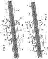
- the fastening device 1 according to the invention is in particular in the FIGS. 5 and 6 shown.
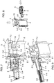
- the device according to the invention is in the FIGS. 1 to 4 and 7 to 9 shown together with optional parts as a fixing set.
- the device 1 according to the invention can also be used for attaching a sanitary object or the like without or with parts other than the optional parts of the fastening set.
- the mounting frame usually has at least two vertically aligned hollow profile bars 2, which are interconnected by one or more cross members (cross members).
- the hollow profile bars 2 may for example consist of square tubes or open profile bars, which are formed in cross-section substantially C-shaped.
- the hollow profile bars 2 can have longitudinal grooves 2.1, 2.2 formed on at least two of their adjacent longitudinal edges, which serve for the positive clamping of a connector for fastening one or more further hollow profile bars.
- the fastening set 1 is composed of a fastening part 3 to be fastened to a building wall, a bolt-shaped or rod-shaped screw element 4, a channel-shaped connecting part 5 which can be detachably connected to the mounting frame, and a latch 6 which is movable axially relative to the longitudinal axis of the screw element 4.
- the screw 4 is designed as a threaded rod. It has at least over a longitudinal section of an external thread 4.1.
- the connecting part 5 has a fastening section 5.1, via which it can be positively connected to the mounting frame.
- the attachment portion 5.1 is formed such that the connecting part 5 can be axially fixed by means of a male part 7 on the mounting frame.
- the attachment portion for this purpose has a gap 5.2, in which a portion of the mounting frame, namely a portion of the hollow profile bar 2 delimiting the passage opening 2.4 can be introduced.
- the gap 5.2 is defined by two flanges 5.3, 5.4 formed on the channel-shaped connecting part.
- the arranged at the front end of the channel-shaped connecting part 5 flange 5.3 is preferably circular or cylindrical.
- the axially spaced flange 5.4 is non-circular, for example, oval.
- the gap 5.2 or axial distance between the two flanges 5.3, 5.4 corresponds to the wall thickness or is slightly larger than the wall thickness of the hollow profile bar. 2
- the two through holes 2.3, 2.4 of the hollow profile bar 2 are also formed differently.
- the opening 2.3, which is incorporated in the space facing hollow profile bar side, is preferably designed as a circular hole, while the other opening 2.4, which is incorporated in the building wall facing the hollow profile bar side, is designed as an oval hole.
- the smallest inner width of the oval hole 2.4 is significantly smaller than the diameter the other opening 2.3 and also significantly smaller than the outer diameter of the circular flange 5.3 of the channel-shaped connecting part.
- the passage openings 2.3, 2.4 are dimensioned so that the connecting part 5 can be inserted through the circular opening 2.3 as far into the oval opening 2.4 until the circular flange 5.3 abuts against the inside of the oval opening 2.4 having wall 2.5 of the hollow profile bar 2 ( see. FIGS. 8 and 9 ).
- the oval flange 5.4 is passed through the oval hole 2.4 and is then located on the outside of the wall 2.5.
- the plug-in part 7 is preferably designed as a plug or cap to close the upper end opening 2.6 of the hollow profile bar 2.
- the plug-in part 7, which can also be referred to as a closure cap, has a lid-like section 7.1, the upper side of which is preferably substantially planar. At the bottom of the lid-like portion 7.1 2 plug-in projections 7.2, 7.3 are formed in the hollow profile bar.
- One of these projections is formed, for example, in the form of a circumferential collar 7.2, which has four substantially perpendicular to each other arranged side portions, wherein the respective side portion has a concave recess 7.21. In one of these recesses 7.21 partially engages the circular flange 5.3 of the connecting part 5 a.
- the side portions of the collar 7.2 extend in the assembled state of the closure cap 7 near or close to the inner sides of the hollow profile bar 2 (see. FIGS. 2 and 4 ).
- the other projections 7.3 of the cap 7 are disposed within the collar 7.2 and protrude significantly deeper into the hollow profile bar 2 as the collar-shaped projection 7.2.
- the projections 7.3 each have a substantially L-shaped or angular cross-sectional profile. They limit a cross-shaped passage (cf. Fig. 9 ), wherein the bolt or rod-shaped screw (threaded rod) 4 in the assembled state of the fastening set 1 coaxial with one of the intersecting axes of the passage 8 extends.
- vertically extending edges 7.31 of two of the projections 7.3 are directly or with little play on the circular flange 5.3 of the connecting part used, so that the connecting part 5.3 is fixed axially to the mounting frame or the hollow profile bar 2.
- the mounting part 3 to be attached to a building wall has a threaded hole 3.1 into which the screw element 4 can be screwed.
- the fastening part 3 has a plate-shaped section 3.2 with a through opening 3.3 for attaching a fastening screw (not shown), wherein the head of the screw preferably rests in the mounted state with a washer on the inside of the fastening part 3.
- the passage opening 3.3 is preferably formed as a slot.
- the fastening part 3 of the plate-shaped portion projecting webs 3.4.
- the webs 3.4 include a screw hole 3.5 having the threaded hole 3.1 for screwing in the screw element 4 or are integrally formed on the screw dome 3.5.
- the mounting frame facing the end of the screw 3.5 and the mounting frame facing edges of the webs 3.4 preferably close substantially flush with each other.
- the screw (threaded rod) 4 is guided axially displaceably in the channel-shaped connecting part 5.
- the connecting part 5 has a sleeve-shaped section 5.5, to which a channel-shaped section 5.6 connects axially.
- the flanges 5.3, 5.4 are arranged on the sleeve-shaped section 5.5.
- the connecting part 5 has along its tubular portion 5.5 an oval inner cross-sectional area.
- the inside of the sleeve-shaped portion 5.5 is preferably smooth or substantially smooth.
- the smallest inner width of the oval inner cross-sectional area of the sleeve-shaped portion 5.4 is greater than the outer diameter of the thread 4.1 of the screw 4.
- the channel-shaped portion 5.6 of the connecting part has on the inside a channel-shaped inner thread 5.7 (see. Fig. 5 . 7 and 9 ).
- the inner part thread 5.7 is formed to match the external thread 4.1 of the screw.
- He is axially displaceable to the longitudinal axis of the connecting part 5 from a non-contact position to a contact position and vice versa displaced and has a bolt or rod-shaped screw member 4 facing contact portion 6.1, in the Contact position on the external thread 4.1 of the screw rests.
- the contact portion 6.1 of the bolt is formed as a projection.
- the longitudinal opening 5.61 of the channel-shaped section 5.6 of the connecting part defines an axial guide for the bolt 6, the contact section 6.1 of the bolt being received in the locking position in the longitudinal opening 5.61.
- the channel-shaped connecting part 5 on its outer side has two radial paragraphs 5.8, 5.9, which are arranged at opposite peripheral portions of the connecting part 5 and axially spaced from each other. Both paragraphs 5.8, 5.9 each have an obliquely to the longitudinal axis of the connecting part 5 extending sliding edge or sliding surface 5.81, 5.91.
- the two sliding edges or sliding surfaces 5.81, 5.91 are formed at mutually facing ends of the two paragraphs 5.8, 5.9.
- an obliquely to the longitudinal axis of the connecting part 5 extending sliding edge or sliding surface 5.10 is formed.
- the latch 6 has a sliding edge or sliding surface 6.8 assigned to the sliding edges or sliding surfaces 5.81, 5.10, which likewise extends obliquely to the longitudinal axis of the bolt 6 or of the connecting part 5.
- the channel-shaped connecting part 5 on its outer side axially spaced-apart recesses 5.11, 5.12, which is associated with a connected to the latch 6 locking element 6.2.
- the locking element 6.2 is formed for example in the form of a resilient locking tab. It engages in two different positions of the bolt 6 relative to the connecting part 5 in one of the two recesses 5.11, 5.12.
- the depressions 5.11, 5.12 are assigned on the one hand to an unlocking state and on the other hand to a locking state.
- the possible directions of movement of the bolt 6 are marked by embossed or printed double arrows 6.3.
- the latch 6 is provided with two symbols 6.4, 6.5, which symbolize a closed and an open padlock and in combination with the double arrows 6.3 indicate the direction of displacement for setting the unlocking state or the locking state.
- the latch 6 has on its outer surface two oppositely disposed rib surfaces 6.6, 6.7, which facilitate the manual, tool-free displacement of the bolt 6 as slip-resistant gripping surfaces.
- the latch 6 together with the channel-shaped connecting part 5 forms a (two-part) nut.
- the bolt 6 can be rotated together with the connecting part 5 about the longitudinal axis of the screw 4 and thus a fine adjustment of the mounting depth of the mounting frame can be made.
- For a quick coarse adjustment of the installation depth of the bolt 6 is pushed into the unlocked position while the engagement of the inner part of thread 5.7 of the connecting part 5 in the external thread 4.1 of the screw 4 solved by a radial movement of the connecting part 5. Then, the screw (threaded rod) 4 and the channel-shaped connecting part 5 relative to each other axially displaced and thus the mounting depth of the mounting frame can be adjusted quickly and roughly.
Landscapes
- Engineering & Computer Science (AREA)
- General Engineering & Computer Science (AREA)
- Health & Medical Sciences (AREA)
- Life Sciences & Earth Sciences (AREA)
- Hydrology & Water Resources (AREA)
- Public Health (AREA)
- Water Supply & Treatment (AREA)
- Mechanical Engineering (AREA)
- Environmental & Geological Engineering (AREA)
- Connection Of Plates (AREA)
- Mutual Connection Of Rods And Tubes (AREA)
Priority Applications (1)
| Application Number | Priority Date | Filing Date | Title |
|---|---|---|---|
| PL18160256T PL3404151T3 (pl) | 2017-05-17 | 2018-03-06 | Urządzenie do mocowania obiektów sanitarnych i zastosowanie takiego urządzenia |
Applications Claiming Priority (1)
| Application Number | Priority Date | Filing Date | Title |
|---|---|---|---|
| DE102017110764.9A DE102017110764A1 (de) | 2017-05-17 | 2017-05-17 | Vorrichtung zum Befestigen eines Sanitärgegenstandes und Verwendung einer solchen Vorrichtung |
Publications (2)
| Publication Number | Publication Date |
|---|---|
| EP3404151A1 true EP3404151A1 (fr) | 2018-11-21 |
| EP3404151B1 EP3404151B1 (fr) | 2021-02-24 |
Family
ID=61581011
Family Applications (1)
| Application Number | Title | Priority Date | Filing Date |
|---|---|---|---|
| EP18160256.6A Active EP3404151B1 (fr) | 2017-05-17 | 2018-03-06 | Dispositif de fixation d'un objet sanitaire et utilisation d'un tel dispositif |
Country Status (5)
| Country | Link |
|---|---|
| EP (1) | EP3404151B1 (fr) |
| DE (1) | DE102017110764A1 (fr) |
| DK (1) | DK3404151T3 (fr) |
| ES (1) | ES2861748T3 (fr) |
| PL (1) | PL3404151T3 (fr) |
Cited By (5)
| Publication number | Priority date | Publication date | Assignee | Title |
|---|---|---|---|---|
| EP3441536A1 (fr) * | 2017-08-11 | 2019-02-13 | GROHEDAL Sanitärsysteme GmbH | Dispositif de fixation d'un cadre pour une unité sanitaire |
| EP3926185A1 (fr) * | 2020-06-19 | 2021-12-22 | Geberit International AG | Support mural |
| CN114703929A (zh) * | 2022-03-29 | 2022-07-05 | 厦门倍杰特科技有限公司 | 一种挂墙物件的锁紧机构 |
| EP4039897A1 (fr) | 2021-02-04 | 2022-08-10 | Geberit International AG | Support mural |
| WO2022167209A1 (fr) | 2021-02-03 | 2022-08-11 | Geberit International Ag | Support mural |
Citations (5)
| Publication number | Priority date | Publication date | Assignee | Title |
|---|---|---|---|---|
| DE20068C (de) * | A. wagner in Radevormwald | Versetzbare Schraubenmutter | ||
| FR1070804A (fr) * | 1952-02-20 | 1954-08-17 | Boehler & Co Ag Geb | Dispositif de serrage rapide à vis |
| DE19958627A1 (de) * | 1999-12-03 | 2000-04-27 | Eduard Janssen | Schraubmutter |
| FR2874040A1 (fr) * | 2004-08-06 | 2006-02-10 | L R Etanco Soc Par Actions Sim | Dispositif pour la fixation de panneaux sur une structure support fixe |
| EP1990547A2 (fr) * | 2007-05-09 | 2008-11-12 | Erico International Corporation | Pinces et connecteurs de poutres structurelles |
Family Cites Families (1)
| Publication number | Priority date | Publication date | Assignee | Title |
|---|---|---|---|---|
| PL203127B1 (pl) | 2001-05-21 | 2009-08-31 | Geberit Technik Ag | Wspornik przyścienny ramy montażowej urządzeń sanitarnych |
-
2017
- 2017-05-17 DE DE102017110764.9A patent/DE102017110764A1/de not_active Withdrawn
-
2018
- 2018-03-06 DK DK18160256.6T patent/DK3404151T3/da active
- 2018-03-06 PL PL18160256T patent/PL3404151T3/pl unknown
- 2018-03-06 EP EP18160256.6A patent/EP3404151B1/fr active Active
- 2018-03-06 ES ES18160256T patent/ES2861748T3/es active Active
Patent Citations (5)
| Publication number | Priority date | Publication date | Assignee | Title |
|---|---|---|---|---|
| DE20068C (de) * | A. wagner in Radevormwald | Versetzbare Schraubenmutter | ||
| FR1070804A (fr) * | 1952-02-20 | 1954-08-17 | Boehler & Co Ag Geb | Dispositif de serrage rapide à vis |
| DE19958627A1 (de) * | 1999-12-03 | 2000-04-27 | Eduard Janssen | Schraubmutter |
| FR2874040A1 (fr) * | 2004-08-06 | 2006-02-10 | L R Etanco Soc Par Actions Sim | Dispositif pour la fixation de panneaux sur une structure support fixe |
| EP1990547A2 (fr) * | 2007-05-09 | 2008-11-12 | Erico International Corporation | Pinces et connecteurs de poutres structurelles |
Cited By (6)
| Publication number | Priority date | Publication date | Assignee | Title |
|---|---|---|---|---|
| EP3441536A1 (fr) * | 2017-08-11 | 2019-02-13 | GROHEDAL Sanitärsysteme GmbH | Dispositif de fixation d'un cadre pour une unité sanitaire |
| EP3926185A1 (fr) * | 2020-06-19 | 2021-12-22 | Geberit International AG | Support mural |
| WO2022167209A1 (fr) | 2021-02-03 | 2022-08-11 | Geberit International Ag | Support mural |
| EP4039897A1 (fr) | 2021-02-04 | 2022-08-10 | Geberit International AG | Support mural |
| CN114703929A (zh) * | 2022-03-29 | 2022-07-05 | 厦门倍杰特科技有限公司 | 一种挂墙物件的锁紧机构 |
| CN114703929B (zh) * | 2022-03-29 | 2023-05-30 | 厦门倍杰特科技有限公司 | 一种挂墙物件的锁紧机构 |
Also Published As
| Publication number | Publication date |
|---|---|
| EP3404151B1 (fr) | 2021-02-24 |
| ES2861748T3 (es) | 2021-10-06 |
| DE102017110764A1 (de) | 2018-11-22 |
| PL3404151T3 (pl) | 2021-06-14 |
| DK3404151T3 (da) | 2021-04-26 |
Similar Documents
| Publication | Publication Date | Title |
|---|---|---|
| EP3404151B1 (fr) | Dispositif de fixation d'un objet sanitaire et utilisation d'un tel dispositif | |
| DE60106980T2 (de) | Hebelbetätigter Verschluss für Teleskopstange | |
| DE102014110638A1 (de) | Schnell montierbare und demontierbare Schraubmuffe | |
| EP3180527B1 (fr) | Dispositif de fixation et système de fixation, en particulier pour la fixation d'un objet sanitaire | |
| EP2055867A1 (fr) | Poignée dotée d'une garniture de fermeture | |
| EP3760076A1 (fr) | Broche de raccordement pour parties de meuble | |
| EP3211145A1 (fr) | Dispositif de fixation pour un objet sanitaire suspendu au mur | |
| EP3404153B1 (fr) | Ensemble de fixation destiné à la fixation d'un chassis de montage pour objets sanitaires et utilisation d'un tel ensemble de fixation | |
| EP1870526A1 (fr) | Robinet sanitaire | |
| EP0521490B1 (fr) | Arrangement de deux éléments de construction connectés télescopiquement l'un avec l'autre | |
| EP3586415B1 (fr) | Accouplement à fiche avec antitraction pour un câble de raccordement | |
| EP3625417A1 (fr) | Bras de commande réglable en longueur | |
| EP3404152B1 (fr) | Ensemble de fixation destiné à la fixation d'un plateau de manutention pour objets sanitaires et utilisation d'un tel ensemble de fixation | |
| EP2985477A1 (fr) | Dispositif de fixation et systeme de fixation en particulier destine a fixer un objet sanitaire | |
| EP2574799A1 (fr) | Agencement de raccordement télescopable | |
| EP0555633B1 (fr) | Garniture pour poignée de porte | |
| DE202016101091U1 (de) | Türverriegelung | |
| DE60038654T2 (de) | Klemmhalterung für Stütz- und Verbindungselemente | |
| DE102005000195A1 (de) | Gleitstück für einen Beschlag | |
| EP4047219B1 (fr) | Unité de montage pourvu d'au moins un rail de montage, ainsi qu'au moins un clip de retenue | |
| DE19545945C1 (de) | Wasserauslaufarmatur mit lösbarem Armaturenkörper | |
| EP1457607A2 (fr) | Dispositif pour fixer une conduite | |
| EP3535824B1 (fr) | Support de jeu de barres et ensemble correspondant | |
| EP3269903B1 (fr) | Garniture à rosette pour poussoir de portes ou de fenêtres | |
| DE10001662A1 (de) | Schutzbeschlag |
Legal Events
| Date | Code | Title | Description |
|---|---|---|---|
| PUAI | Public reference made under article 153(3) epc to a published international application that has entered the european phase |
Free format text: ORIGINAL CODE: 0009012 |
|
| STAA | Information on the status of an ep patent application or granted ep patent |
Free format text: STATUS: THE APPLICATION HAS BEEN PUBLISHED |
|
| AK | Designated contracting states |
Kind code of ref document: A1 Designated state(s): AL AT BE BG CH CY CZ DE DK EE ES FI FR GB GR HR HU IE IS IT LI LT LU LV MC MK MT NL NO PL PT RO RS SE SI SK SM TR |
|
| AX | Request for extension of the european patent |
Extension state: BA ME |
|
| STAA | Information on the status of an ep patent application or granted ep patent |
Free format text: STATUS: REQUEST FOR EXAMINATION WAS MADE |
|
| 17P | Request for examination filed |
Effective date: 20190515 |
|
| RBV | Designated contracting states (corrected) |
Designated state(s): AL AT BE BG CH CY CZ DE DK EE ES FI FR GB GR HR HU IE IS IT LI LT LU LV MC MK MT NL NO PL PT RO RS SE SI SK SM TR |
|
| GRAP | Despatch of communication of intention to grant a patent |
Free format text: ORIGINAL CODE: EPIDOSNIGR1 |
|
| STAA | Information on the status of an ep patent application or granted ep patent |
Free format text: STATUS: GRANT OF PATENT IS INTENDED |
|
| INTG | Intention to grant announced |
Effective date: 20201118 |
|
| GRAS | Grant fee paid |
Free format text: ORIGINAL CODE: EPIDOSNIGR3 |
|
| GRAA | (expected) grant |
Free format text: ORIGINAL CODE: 0009210 |
|
| STAA | Information on the status of an ep patent application or granted ep patent |
Free format text: STATUS: THE PATENT HAS BEEN GRANTED |
|
| AK | Designated contracting states |
Kind code of ref document: B1 Designated state(s): AL AT BE BG CH CY CZ DE DK EE ES FI FR GB GR HR HU IE IS IT LI LT LU LV MC MK MT NL NO PL PT RO RS SE SI SK SM TR |
|
| REG | Reference to a national code |
Ref country code: CH Ref legal event code: EP |
|
| REG | Reference to a national code |
Ref country code: DE Ref legal event code: R096 Ref document number: 502018003950 Country of ref document: DE |
|
| REG | Reference to a national code |
Ref country code: AT Ref legal event code: REF Ref document number: 1364595 Country of ref document: AT Kind code of ref document: T Effective date: 20210315 Ref country code: CH Ref legal event code: NV Representative=s name: SCHMAUDER AND PARTNER AG PATENT- UND MARKENANW, CH |
|
| REG | Reference to a national code |
Ref country code: IE Ref legal event code: FG4D Free format text: LANGUAGE OF EP DOCUMENT: GERMAN |
|
| REG | Reference to a national code |
Ref country code: NL Ref legal event code: FP |
|
| REG | Reference to a national code |
Ref country code: DK Ref legal event code: T3 Effective date: 20210420 |
|
| REG | Reference to a national code |
Ref country code: LT Ref legal event code: MG9D |
|
| PG25 | Lapsed in a contracting state [announced via postgrant information from national office to epo] |
Ref country code: BG Free format text: LAPSE BECAUSE OF FAILURE TO SUBMIT A TRANSLATION OF THE DESCRIPTION OR TO PAY THE FEE WITHIN THE PRESCRIBED TIME-LIMIT Effective date: 20210524 Ref country code: LT Free format text: LAPSE BECAUSE OF FAILURE TO SUBMIT A TRANSLATION OF THE DESCRIPTION OR TO PAY THE FEE WITHIN THE PRESCRIBED TIME-LIMIT Effective date: 20210224 Ref country code: FI Free format text: LAPSE BECAUSE OF FAILURE TO SUBMIT A TRANSLATION OF THE DESCRIPTION OR TO PAY THE FEE WITHIN THE PRESCRIBED TIME-LIMIT Effective date: 20210224 Ref country code: HR Free format text: LAPSE BECAUSE OF FAILURE TO SUBMIT A TRANSLATION OF THE DESCRIPTION OR TO PAY THE FEE WITHIN THE PRESCRIBED TIME-LIMIT Effective date: 20210224 Ref country code: GR Free format text: LAPSE BECAUSE OF FAILURE TO SUBMIT A TRANSLATION OF THE DESCRIPTION OR TO PAY THE FEE WITHIN THE PRESCRIBED TIME-LIMIT Effective date: 20210525 Ref country code: PT Free format text: LAPSE BECAUSE OF FAILURE TO SUBMIT A TRANSLATION OF THE DESCRIPTION OR TO PAY THE FEE WITHIN THE PRESCRIBED TIME-LIMIT Effective date: 20210624 Ref country code: NO Free format text: LAPSE BECAUSE OF FAILURE TO SUBMIT A TRANSLATION OF THE DESCRIPTION OR TO PAY THE FEE WITHIN THE PRESCRIBED TIME-LIMIT Effective date: 20210524 |
|
| PG25 | Lapsed in a contracting state [announced via postgrant information from national office to epo] |
Ref country code: RS Free format text: LAPSE BECAUSE OF FAILURE TO SUBMIT A TRANSLATION OF THE DESCRIPTION OR TO PAY THE FEE WITHIN THE PRESCRIBED TIME-LIMIT Effective date: 20210224 Ref country code: LV Free format text: LAPSE BECAUSE OF FAILURE TO SUBMIT A TRANSLATION OF THE DESCRIPTION OR TO PAY THE FEE WITHIN THE PRESCRIBED TIME-LIMIT Effective date: 20210224 Ref country code: SE Free format text: LAPSE BECAUSE OF FAILURE TO SUBMIT A TRANSLATION OF THE DESCRIPTION OR TO PAY THE FEE WITHIN THE PRESCRIBED TIME-LIMIT Effective date: 20210224 |
|
| PG25 | Lapsed in a contracting state [announced via postgrant information from national office to epo] |
Ref country code: IS Free format text: LAPSE BECAUSE OF FAILURE TO SUBMIT A TRANSLATION OF THE DESCRIPTION OR TO PAY THE FEE WITHIN THE PRESCRIBED TIME-LIMIT Effective date: 20210624 |
|
| REG | Reference to a national code |
Ref country code: ES Ref legal event code: FG2A Ref document number: 2861748 Country of ref document: ES Kind code of ref document: T3 Effective date: 20211006 |
|
| PG25 | Lapsed in a contracting state [announced via postgrant information from national office to epo] |
Ref country code: SM Free format text: LAPSE BECAUSE OF FAILURE TO SUBMIT A TRANSLATION OF THE DESCRIPTION OR TO PAY THE FEE WITHIN THE PRESCRIBED TIME-LIMIT Effective date: 20210224 Ref country code: EE Free format text: LAPSE BECAUSE OF FAILURE TO SUBMIT A TRANSLATION OF THE DESCRIPTION OR TO PAY THE FEE WITHIN THE PRESCRIBED TIME-LIMIT Effective date: 20210224 Ref country code: CZ Free format text: LAPSE BECAUSE OF FAILURE TO SUBMIT A TRANSLATION OF THE DESCRIPTION OR TO PAY THE FEE WITHIN THE PRESCRIBED TIME-LIMIT Effective date: 20210224 |
|
| REG | Reference to a national code |
Ref country code: DE Ref legal event code: R097 Ref document number: 502018003950 Country of ref document: DE |
|
| PG25 | Lapsed in a contracting state [announced via postgrant information from national office to epo] |
Ref country code: RO Free format text: LAPSE BECAUSE OF FAILURE TO SUBMIT A TRANSLATION OF THE DESCRIPTION OR TO PAY THE FEE WITHIN THE PRESCRIBED TIME-LIMIT Effective date: 20210224 Ref country code: SK Free format text: LAPSE BECAUSE OF FAILURE TO SUBMIT A TRANSLATION OF THE DESCRIPTION OR TO PAY THE FEE WITHIN THE PRESCRIBED TIME-LIMIT Effective date: 20210224 Ref country code: MC Free format text: LAPSE BECAUSE OF FAILURE TO SUBMIT A TRANSLATION OF THE DESCRIPTION OR TO PAY THE FEE WITHIN THE PRESCRIBED TIME-LIMIT Effective date: 20210224 |
|
| PLBE | No opposition filed within time limit |
Free format text: ORIGINAL CODE: 0009261 |
|
| STAA | Information on the status of an ep patent application or granted ep patent |
Free format text: STATUS: NO OPPOSITION FILED WITHIN TIME LIMIT |
|
| PG25 | Lapsed in a contracting state [announced via postgrant information from national office to epo] |
Ref country code: LU Free format text: LAPSE BECAUSE OF NON-PAYMENT OF DUE FEES Effective date: 20210306 Ref country code: AL Free format text: LAPSE BECAUSE OF FAILURE TO SUBMIT A TRANSLATION OF THE DESCRIPTION OR TO PAY THE FEE WITHIN THE PRESCRIBED TIME-LIMIT Effective date: 20210224 Ref country code: IE Free format text: LAPSE BECAUSE OF NON-PAYMENT OF DUE FEES Effective date: 20210306 |
|
| 26N | No opposition filed |
Effective date: 20211125 |
|
| PG25 | Lapsed in a contracting state [announced via postgrant information from national office to epo] |
Ref country code: SI Free format text: LAPSE BECAUSE OF FAILURE TO SUBMIT A TRANSLATION OF THE DESCRIPTION OR TO PAY THE FEE WITHIN THE PRESCRIBED TIME-LIMIT Effective date: 20210224 |
|
| PG25 | Lapsed in a contracting state [announced via postgrant information from national office to epo] |
Ref country code: IS Free format text: LAPSE BECAUSE OF FAILURE TO SUBMIT A TRANSLATION OF THE DESCRIPTION OR TO PAY THE FEE WITHIN THE PRESCRIBED TIME-LIMIT Effective date: 20210624 |
|
| PGFP | Annual fee paid to national office [announced via postgrant information from national office to epo] |
Ref country code: FR Payment date: 20230323 Year of fee payment: 6 Ref country code: DK Payment date: 20230329 Year of fee payment: 6 |
|
| PGFP | Annual fee paid to national office [announced via postgrant information from national office to epo] |
Ref country code: PL Payment date: 20230228 Year of fee payment: 6 Ref country code: IT Payment date: 20230323 Year of fee payment: 6 Ref country code: BE Payment date: 20230322 Year of fee payment: 6 |
|
| PG25 | Lapsed in a contracting state [announced via postgrant information from national office to epo] |
Ref country code: CY Free format text: LAPSE BECAUSE OF FAILURE TO SUBMIT A TRANSLATION OF THE DESCRIPTION OR TO PAY THE FEE WITHIN THE PRESCRIBED TIME-LIMIT Effective date: 20210224 |
|
| PG25 | Lapsed in a contracting state [announced via postgrant information from national office to epo] |
Ref country code: HU Free format text: LAPSE BECAUSE OF FAILURE TO SUBMIT A TRANSLATION OF THE DESCRIPTION OR TO PAY THE FEE WITHIN THE PRESCRIBED TIME-LIMIT; INVALID AB INITIO Effective date: 20180306 |
|
| PGFP | Annual fee paid to national office [announced via postgrant information from national office to epo] |
Ref country code: ES Payment date: 20230421 Year of fee payment: 6 Ref country code: CH Payment date: 20230401 Year of fee payment: 6 |
|
| PGFP | Annual fee paid to national office [announced via postgrant information from national office to epo] |
Ref country code: NL Payment date: 20240321 Year of fee payment: 7 |
|
| PGFP | Annual fee paid to national office [announced via postgrant information from national office to epo] |
Ref country code: AT Payment date: 20240322 Year of fee payment: 7 |
|
| PG25 | Lapsed in a contracting state [announced via postgrant information from national office to epo] |
Ref country code: MK Free format text: LAPSE BECAUSE OF FAILURE TO SUBMIT A TRANSLATION OF THE DESCRIPTION OR TO PAY THE FEE WITHIN THE PRESCRIBED TIME-LIMIT Effective date: 20210224 |
|
| PGFP | Annual fee paid to national office [announced via postgrant information from national office to epo] |
Ref country code: DE Payment date: 20240321 Year of fee payment: 7 Ref country code: GB Payment date: 20240321 Year of fee payment: 7 |