EP3404151A1 - Device for fixing a sanitary object and use of same - Google Patents
Device for fixing a sanitary object and use of same Download PDFInfo
- Publication number
- EP3404151A1 EP3404151A1 EP18160256.6A EP18160256A EP3404151A1 EP 3404151 A1 EP3404151 A1 EP 3404151A1 EP 18160256 A EP18160256 A EP 18160256A EP 3404151 A1 EP3404151 A1 EP 3404151A1
- Authority
- EP
- European Patent Office
- Prior art keywords
- connecting part
- shaped
- channel
- bolt
- screw
- Prior art date
- Legal status (The legal status is an assumption and is not a legal conclusion. Google has not performed a legal analysis and makes no representation as to the accuracy of the status listed.)
- Granted
Links
- 230000002093 peripheral effect Effects 0.000 claims description 3
- 238000006073 displacement reaction Methods 0.000 description 6
- 238000004040 coloring Methods 0.000 description 1
- 238000003780 insertion Methods 0.000 description 1
- 230000037431 insertion Effects 0.000 description 1
- 238000009434 installation Methods 0.000 description 1
- 230000013011 mating Effects 0.000 description 1
- 238000012986 modification Methods 0.000 description 1
- 230000004048 modification Effects 0.000 description 1
- 230000007704 transition Effects 0.000 description 1
Images

Classifications
-
- E—FIXED CONSTRUCTIONS
- E03—WATER SUPPLY; SEWERAGE
- E03D—WATER-CLOSETS OR URINALS WITH FLUSHING DEVICES; FLUSHING VALVES THEREFOR
- E03D11/00—Other component parts of water-closets, e.g. noise-reducing means in the flushing system, flushing pipes mounted in the bowl, seals for the bowl outlet, devices preventing overflow of the bowl contents; devices forming a water seal in the bowl after flushing, devices eliminating obstructions in the bowl outlet or preventing backflow of water and excrements from the waterpipe
- E03D11/13—Parts or details of bowls; Special adaptations of pipe joints or couplings for use with bowls, e.g. provisions in bowl construction preventing backflow of waste-water from the bowl in the flushing pipe or cistern, provisions for a secondary flushing, for noise-reducing
- E03D11/14—Means for connecting the bowl to the wall, e.g. to a wall outlet
- E03D11/143—Mounting frames for toilets and urinals
-
- E—FIXED CONSTRUCTIONS
- E03—WATER SUPPLY; SEWERAGE
- E03C—DOMESTIC PLUMBING INSTALLATIONS FOR FRESH WATER OR WASTE WATER; SINKS
- E03C1/00—Domestic plumbing installations for fresh water or waste water; Sinks
- E03C1/12—Plumbing installations for waste water; Basins or fountains connected thereto; Sinks
- E03C1/32—Holders or supports for basins
- E03C1/322—Holders or supports for basins connected to the wall only
-
- E—FIXED CONSTRUCTIONS
- E03—WATER SUPPLY; SEWERAGE
- E03D—WATER-CLOSETS OR URINALS WITH FLUSHING DEVICES; FLUSHING VALVES THEREFOR
- E03D11/00—Other component parts of water-closets, e.g. noise-reducing means in the flushing system, flushing pipes mounted in the bowl, seals for the bowl outlet, devices preventing overflow of the bowl contents; devices forming a water seal in the bowl after flushing, devices eliminating obstructions in the bowl outlet or preventing backflow of water and excrements from the waterpipe
- E03D11/13—Parts or details of bowls; Special adaptations of pipe joints or couplings for use with bowls, e.g. provisions in bowl construction preventing backflow of waste-water from the bowl in the flushing pipe or cistern, provisions for a secondary flushing, for noise-reducing
- E03D11/14—Means for connecting the bowl to the wall, e.g. to a wall outlet
-
- F—MECHANICAL ENGINEERING; LIGHTING; HEATING; WEAPONS; BLASTING
- F16—ENGINEERING ELEMENTS AND UNITS; GENERAL MEASURES FOR PRODUCING AND MAINTAINING EFFECTIVE FUNCTIONING OF MACHINES OR INSTALLATIONS; THERMAL INSULATION IN GENERAL
- F16B—DEVICES FOR FASTENING OR SECURING CONSTRUCTIONAL ELEMENTS OR MACHINE PARTS TOGETHER, e.g. NAILS, BOLTS, CIRCLIPS, CLAMPS, CLIPS OR WEDGES; JOINTS OR JOINTING
- F16B37/00—Nuts or like thread-engaging members
- F16B37/08—Quickly-detachable or mountable nuts, e.g. consisting of two or more parts; Nuts movable along the bolt after tilting the nut
- F16B37/0807—Nuts engaged from the end of the bolt, e.g. axially slidable nuts
- F16B37/0814—Nuts engaged from the end of the bolt, e.g. axially slidable nuts movable along the bolt after tilting the nut
Definitions
- the invention relates to a device for fastening a sanitary object, in particular a washbasin or a mounting frame for holding a sanitary object, on a building wall or on a support, with a bolt-shaped or rod-shaped screw member having at least along a longitudinal section an external thread, and a screw nut-like counter element ,
- This wall bracket called device comprises a connecting rod which is attached at one end to a mounting frame for sanitary appliances, and a fixing member which is attached to the other end of the connecting rod and fixed to a building wall.
- the connecting rod and the fastening part are releasably connected to each other by means of an attached bolt, which is designed as a U-shaped clip nut.
- the fastening part has a shaft with a smooth-walled passage, into which the end of the connecting rod facing away from the mounting frame is inserted.
- the shaft is provided with openings, in which the clip nut is inserted as a bolt and thus attached transversely to the longitudinal axis of the connecting rod on the same.
- This device allows a quick mounting of the mounting frame with a coarse adjustment of the mounting depth and a subsequent fine adjustment.
- this known wall mount appears to be even better in terms of a simple, easy to understand for the user handling.
- the present invention seeks to provide a fastening device of the type mentioned, which is inexpensive to produce and offers an easy-to-use quick adjustment without tools.
- the fastening device is characterized in that the screw nut-like counter-element is composed of a channel-shaped, an inner thread part having a connecting part and a bolt, wherein the connecting part has a clearance into which the screw member is radially displaceable in order to release the screw member from the inner thread, said Latch on the connecting part substantially axially displaceable to the longitudinal axis of the screw member from a non-contact position to a contact position and vice versa, and wherein the latch in the contact position holds the screw in engagement with the inner thread.
- the fastening device according to the invention can be produced inexpensively and can be easily and quickly adjusted without tools.
- the inner thread of the channel-shaped connecting part can also consist of several internal threads.
- the channel-shaped connecting part preferably has a sleeve-shaped section, which is adjoined axially by a groove-shaped section.
- the slidable axially to the longitudinal axis of the screw and to the longitudinal axis of the channel-shaped connecting part bolt which can also be referred to as a slide, not only serves the coarse adjustment, but also as a rotary handle for manual fine adjustment of a mounting depth or axial position. Due to the special design of the bolt as an axial slide and rotary handle recognizes and understands the user of the fastening device according to the invention quickly their operation. The quick recognition of the functioning can additionally be increased by a corresponding shape and / or surface design of the bolt.
- typical gripping surfaces, eg corrugations, and / or symbols, eg, arrows, preferably double arrows, and / or locking and / or unlocking symbols are provided or formed on the latch.
- a quick recognition of the mode of operation of the fastening device according to the invention can be optimized, for example, by a different coloring of the components of the fastening device, in particular of bolt and channel-shaped connecting part.
- the channel-shaped connecting part preferably has on its outer side at least two radial shoulders provided on opposite peripheral portions of the connecting part and axially spaced from each other.
- at least one of the shoulders, preferably the respective shoulder has a sliding edge or sliding surface running obliquely to the longitudinal axis of the channel-shaped connecting part.
- the Rigel is ring-shaped or sleeve-shaped.
- a play-free contact of the bolt or rod-shaped screw facing contact portion of the bolt can be secured to the external thread.
- the execution of the bolt as a ring-shaped or sleeve-shaped latch that the bolt is arranged captive or almost captive on the channel-shaped connecting part.
- the bolt does not necessarily have to have a closed ring or sleeve shape. Rather, it is also within the scope of the invention, the ring-shaped or sleeve-shaped latch in the form of an axial slot having executed clamping ring or a correspondingly designed clamping sleeve.
- a further advantageous embodiment of the device according to the invention is characterized in that the internal thread of the channel-shaped connecting part is formed as a channel-shaped partial thread.
- the inner thread of the connecting part serves as a mating thread for the external thread of the bolt or rod-shaped screw.
- the inner thread can also be referred to as a groove-shaped thread root.
- the channel-shaped, the female thread having connecting part and the bolt (slider) together may also be referred to as a two-piece nut.
- the bolt has a projecting contact portion, which faces the screw.
- the channel-shaped connecting part has a channel-shaped portion whose longitudinal opening defines an axial guide for the bolt, wherein the protruding contact portion of the bolt is received in the contact position in the longitudinal opening ,
- the channel-shaped section or the longitudinal opening the channel-shaped connecting part preferably extends over at least half the length of the connecting part.
- a further advantageous embodiment of the fastening device according to the invention provides that the channel-shaped connecting part has on its outer side at least one recess into which a locking element connected to the latch can be latched. As a result, the bolt can be locked in the contact position against unintentional movement in the non-contact position or vice versa.
- the channel-shaped connecting part on a radially projecting attachment portion via which the connecting part is positively connected to a through hole of a mounting frame with the mounting frame connectable.
- a gap is formed in the attachment portion into which a portion of a profile bar can be introduced.
- the gap can be defined by two flanges formed on the channel-shaped connecting part.
- the attachment portion of the channel-shaped connecting part may comprise at least one substantially oval or non-circular flange which can be passed through a correspondingly shaped through hole of the mounting frame, wherein axially spaced from the flange, in the insertion direction, another flange or stop on the connecting part is trained.
- the teaching of the present invention also includes the use of a device according to the invention, in particular in one of the above-mentioned embodiments, for fastening a sanitary object or a mounting frame for one or more sanitary objects, for example for a cistern, a toilet bowl and / or a sink, on a building wall or on a support.
- the device 1 according to the invention shown in the drawing serves for fastening a sanitary object, for example a wash basin or a mounting frame for holding a sanitary object, to a building wall or to a support.
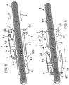
- the fastening device 1 according to the invention is in particular in the FIGS. 5 and 6 shown.
- the device according to the invention is in the FIGS. 1 to 4 and 7 to 9 shown together with optional parts as a fixing set.
- the device 1 according to the invention can also be used for attaching a sanitary object or the like without or with parts other than the optional parts of the fastening set.
- the mounting frame usually has at least two vertically aligned hollow profile bars 2, which are interconnected by one or more cross members (cross members).
- the hollow profile bars 2 may for example consist of square tubes or open profile bars, which are formed in cross-section substantially C-shaped.
- the hollow profile bars 2 can have longitudinal grooves 2.1, 2.2 formed on at least two of their adjacent longitudinal edges, which serve for the positive clamping of a connector for fastening one or more further hollow profile bars.
- the fastening set 1 is composed of a fastening part 3 to be fastened to a building wall, a bolt-shaped or rod-shaped screw element 4, a channel-shaped connecting part 5 which can be detachably connected to the mounting frame, and a latch 6 which is movable axially relative to the longitudinal axis of the screw element 4.
- the screw 4 is designed as a threaded rod. It has at least over a longitudinal section of an external thread 4.1.
- the connecting part 5 has a fastening section 5.1, via which it can be positively connected to the mounting frame.
- the attachment portion 5.1 is formed such that the connecting part 5 can be axially fixed by means of a male part 7 on the mounting frame.
- the attachment portion for this purpose has a gap 5.2, in which a portion of the mounting frame, namely a portion of the hollow profile bar 2 delimiting the passage opening 2.4 can be introduced.
- the gap 5.2 is defined by two flanges 5.3, 5.4 formed on the channel-shaped connecting part.
- the arranged at the front end of the channel-shaped connecting part 5 flange 5.3 is preferably circular or cylindrical.
- the axially spaced flange 5.4 is non-circular, for example, oval.
- the gap 5.2 or axial distance between the two flanges 5.3, 5.4 corresponds to the wall thickness or is slightly larger than the wall thickness of the hollow profile bar. 2
- the two through holes 2.3, 2.4 of the hollow profile bar 2 are also formed differently.
- the opening 2.3, which is incorporated in the space facing hollow profile bar side, is preferably designed as a circular hole, while the other opening 2.4, which is incorporated in the building wall facing the hollow profile bar side, is designed as an oval hole.
- the smallest inner width of the oval hole 2.4 is significantly smaller than the diameter the other opening 2.3 and also significantly smaller than the outer diameter of the circular flange 5.3 of the channel-shaped connecting part.
- the passage openings 2.3, 2.4 are dimensioned so that the connecting part 5 can be inserted through the circular opening 2.3 as far into the oval opening 2.4 until the circular flange 5.3 abuts against the inside of the oval opening 2.4 having wall 2.5 of the hollow profile bar 2 ( see. FIGS. 8 and 9 ).
- the oval flange 5.4 is passed through the oval hole 2.4 and is then located on the outside of the wall 2.5.
- the plug-in part 7 is preferably designed as a plug or cap to close the upper end opening 2.6 of the hollow profile bar 2.
- the plug-in part 7, which can also be referred to as a closure cap, has a lid-like section 7.1, the upper side of which is preferably substantially planar. At the bottom of the lid-like portion 7.1 2 plug-in projections 7.2, 7.3 are formed in the hollow profile bar.
- One of these projections is formed, for example, in the form of a circumferential collar 7.2, which has four substantially perpendicular to each other arranged side portions, wherein the respective side portion has a concave recess 7.21. In one of these recesses 7.21 partially engages the circular flange 5.3 of the connecting part 5 a.
- the side portions of the collar 7.2 extend in the assembled state of the closure cap 7 near or close to the inner sides of the hollow profile bar 2 (see. FIGS. 2 and 4 ).
- the other projections 7.3 of the cap 7 are disposed within the collar 7.2 and protrude significantly deeper into the hollow profile bar 2 as the collar-shaped projection 7.2.
- the projections 7.3 each have a substantially L-shaped or angular cross-sectional profile. They limit a cross-shaped passage (cf. Fig. 9 ), wherein the bolt or rod-shaped screw (threaded rod) 4 in the assembled state of the fastening set 1 coaxial with one of the intersecting axes of the passage 8 extends.
- vertically extending edges 7.31 of two of the projections 7.3 are directly or with little play on the circular flange 5.3 of the connecting part used, so that the connecting part 5.3 is fixed axially to the mounting frame or the hollow profile bar 2.
- the mounting part 3 to be attached to a building wall has a threaded hole 3.1 into which the screw element 4 can be screwed.
- the fastening part 3 has a plate-shaped section 3.2 with a through opening 3.3 for attaching a fastening screw (not shown), wherein the head of the screw preferably rests in the mounted state with a washer on the inside of the fastening part 3.
- the passage opening 3.3 is preferably formed as a slot.
- the fastening part 3 of the plate-shaped portion projecting webs 3.4.
- the webs 3.4 include a screw hole 3.5 having the threaded hole 3.1 for screwing in the screw element 4 or are integrally formed on the screw dome 3.5.
- the mounting frame facing the end of the screw 3.5 and the mounting frame facing edges of the webs 3.4 preferably close substantially flush with each other.
- the screw (threaded rod) 4 is guided axially displaceably in the channel-shaped connecting part 5.
- the connecting part 5 has a sleeve-shaped section 5.5, to which a channel-shaped section 5.6 connects axially.
- the flanges 5.3, 5.4 are arranged on the sleeve-shaped section 5.5.
- the connecting part 5 has along its tubular portion 5.5 an oval inner cross-sectional area.
- the inside of the sleeve-shaped portion 5.5 is preferably smooth or substantially smooth.
- the smallest inner width of the oval inner cross-sectional area of the sleeve-shaped portion 5.4 is greater than the outer diameter of the thread 4.1 of the screw 4.
- the channel-shaped portion 5.6 of the connecting part has on the inside a channel-shaped inner thread 5.7 (see. Fig. 5 . 7 and 9 ).
- the inner part thread 5.7 is formed to match the external thread 4.1 of the screw.
- He is axially displaceable to the longitudinal axis of the connecting part 5 from a non-contact position to a contact position and vice versa displaced and has a bolt or rod-shaped screw member 4 facing contact portion 6.1, in the Contact position on the external thread 4.1 of the screw rests.
- the contact portion 6.1 of the bolt is formed as a projection.
- the longitudinal opening 5.61 of the channel-shaped section 5.6 of the connecting part defines an axial guide for the bolt 6, the contact section 6.1 of the bolt being received in the locking position in the longitudinal opening 5.61.
- the channel-shaped connecting part 5 on its outer side has two radial paragraphs 5.8, 5.9, which are arranged at opposite peripheral portions of the connecting part 5 and axially spaced from each other. Both paragraphs 5.8, 5.9 each have an obliquely to the longitudinal axis of the connecting part 5 extending sliding edge or sliding surface 5.81, 5.91.
- the two sliding edges or sliding surfaces 5.81, 5.91 are formed at mutually facing ends of the two paragraphs 5.8, 5.9.
- an obliquely to the longitudinal axis of the connecting part 5 extending sliding edge or sliding surface 5.10 is formed.
- the latch 6 has a sliding edge or sliding surface 6.8 assigned to the sliding edges or sliding surfaces 5.81, 5.10, which likewise extends obliquely to the longitudinal axis of the bolt 6 or of the connecting part 5.
- the channel-shaped connecting part 5 on its outer side axially spaced-apart recesses 5.11, 5.12, which is associated with a connected to the latch 6 locking element 6.2.
- the locking element 6.2 is formed for example in the form of a resilient locking tab. It engages in two different positions of the bolt 6 relative to the connecting part 5 in one of the two recesses 5.11, 5.12.
- the depressions 5.11, 5.12 are assigned on the one hand to an unlocking state and on the other hand to a locking state.
- the possible directions of movement of the bolt 6 are marked by embossed or printed double arrows 6.3.
- the latch 6 is provided with two symbols 6.4, 6.5, which symbolize a closed and an open padlock and in combination with the double arrows 6.3 indicate the direction of displacement for setting the unlocking state or the locking state.
- the latch 6 has on its outer surface two oppositely disposed rib surfaces 6.6, 6.7, which facilitate the manual, tool-free displacement of the bolt 6 as slip-resistant gripping surfaces.
- the latch 6 together with the channel-shaped connecting part 5 forms a (two-part) nut.
- the bolt 6 can be rotated together with the connecting part 5 about the longitudinal axis of the screw 4 and thus a fine adjustment of the mounting depth of the mounting frame can be made.
- For a quick coarse adjustment of the installation depth of the bolt 6 is pushed into the unlocked position while the engagement of the inner part of thread 5.7 of the connecting part 5 in the external thread 4.1 of the screw 4 solved by a radial movement of the connecting part 5. Then, the screw (threaded rod) 4 and the channel-shaped connecting part 5 relative to each other axially displaced and thus the mounting depth of the mounting frame can be adjusted quickly and roughly.
Abstract
Die Erfindung betrifft eine Vorrichtung (1) zum Befestigen eines Sanitärgegenstandes, insbesondere eines Waschbeckens oder eines Montagegestells zur Halterung eines Sanitärgegenstandes, an einer Gebäudewand oder an einem Träger, mit einem bolzen-oder stangenförmigen Schraubelement (4), das zumindest entlang eines Längenabschnitts ein Außengewinde (4.1) aufweist, und einem schraubenmutterartigen Gegenelement. Damit eine derartige Vorrichtung kostengünstig herstellbar ist und ohne Werkzeug eine einfach zu bedienende Schnellverstellung bietet, sieht die Erfindung vor, dass das Gegenelement aus einem kanalförmigen, ein Innenteilgewinde (5.7) aufweisenden Verbindungsteil (5) und einem Riegel (6) zusammengesetzt ist, wobei das Verbindungsteil (5) einen Freiraum aufweist, in den das Schraubelement (4) radial verschiebbar ist, um das Schraubelement (4) vom Innenteilgewinde (5.7) zu lösen, wobei der Riegel (6) auf dem Verbindungsteil im Wesentlichen axial zur Längsachse des Schraubelements (4) aus einer Nicht-Kontaktstellung in eine Kontaktstellung und umgekehrt verschiebbar ist, und wobei der Riegel (6) in der Kontaktstellung das Schraubelement (4) in Eingriff mit dem Innenteilgewinde (5.7) hält.The invention relates to a device (1) for fastening a sanitary object, in particular a sink or a mounting frame for holding a sanitary object, on a building wall or on a support, with a bolt-or rod-shaped screw member (4), at least along a longitudinal section of an external thread (4.1), and a screw nut-like counter element. In order for such a device can be produced inexpensively and offers an easy-to-use quick adjustment without tools, the invention provides that the counter element of a channel-shaped, an inner part thread (5.7) having connecting part (5) and a latch (6) is composed, said Connecting part (5) has a clearance into which the screw element (4) is radially displaceable in order to release the screw element (4) from the inner part thread (5.7), wherein the latch (6) on the connecting part substantially axially to the longitudinal axis of the screw element ( 4) is displaceable from a non-contact position into a contact position and vice versa, and wherein the latch (6) in the contact position holds the screw element (4) in engagement with the inner part thread (5.7).
Description
Die Erfindung betrifft eine Vorrichtung zum Befestigen eines Sanitärgegenstandes, insbesondere eines Waschbeckens oder eines Montagegestells zur Halterung eines Sanitärgegenstandes, an einer Gebäudewand oder an einem Träger, mit einem bolzen- oder stangenförmigen Schraubelement, das zumindest entlang eines Längenabschnitts ein Außengewinde aufweist, und einem schraubenmutterartigen Gegenelement.The invention relates to a device for fastening a sanitary object, in particular a washbasin or a mounting frame for holding a sanitary object, on a building wall or on a support, with a bolt-shaped or rod-shaped screw member having at least along a longitudinal section an external thread, and a screw nut-like counter element ,
Eine derartige Vorrichtung ist aus der
Davon ausgehend liegt der Erfindung die Aufgabe zugrunde, eine Befestigungsvorrichtung der eingangs genannten Art zu schaffen, die kostengünstig herstellbar ist und ohne Werkzeug eine einfach zu bedienende Schnellverstellung bietet.Based on this, the present invention seeks to provide a fastening device of the type mentioned, which is inexpensive to produce and offers an easy-to-use quick adjustment without tools.
Gelöst wird diese Aufgabe durch eine Vorrichtung mit den im Anspruch 1 angegebenen Merkmalen. Bevorzugte und vorteilhafte Ausgestaltungen der erfindungsgemäßen Befestigungsvorrichtung sind in den Unteransprüchen angegeben.This object is achieved by a device having the features specified in claim 1. Preferred and advantageous embodiments of the fastening device according to the invention are specified in the subclaims.
Die erfindungsgemäße Befestigungsvorrichtung ist dadurch gekennzeichnet, dass das schraubenmutterartige Gegenelement aus einem kanalförmigen, ein Innenteilgewinde aufweisenden Verbindungsteil und einem Riegel zusammengesetzt ist, wobei das Verbindungsteil einen Freiraum aufweist, in den das Schraubelement radial verschiebbar ist, um das Schraubelement vom Innenteilgewinde zu lösen, wobei der Riegel auf dem Verbindungsteil im Wesentlichen axial zur Längsachse des Schraubelements aus einer Nicht-Kontaktstellung in eine Kontaktstellung und umgekehrt verschiebbar ist, und wobei der Riegel in der Kontaktstellung das Schraubelement in Eingriff mit dem Innenteilgewinde hält.The fastening device according to the invention is characterized in that the screw nut-like counter-element is composed of a channel-shaped, an inner thread part having a connecting part and a bolt, wherein the connecting part has a clearance into which the screw member is radially displaceable in order to release the screw member from the inner thread, said Latch on the connecting part substantially axially displaceable to the longitudinal axis of the screw member from a non-contact position to a contact position and vice versa, and wherein the latch in the contact position holds the screw in engagement with the inner thread.
Die erfindungsgemäße Befestigungsvorrichtung lässt sich kostengünstig herstellen und kann ohne Werkzeug einfach und schnell eingestellt werden. Das Innenteilgewinde des kanalförmigen Verbindungsteils kann dabei auch aus mehreren Innenteilgewinden bestehen.The fastening device according to the invention can be produced inexpensively and can be easily and quickly adjusted without tools. The inner thread of the channel-shaped connecting part can also consist of several internal threads.
Das kanalförmige Verbindungsteil weist vorzugsweise einen hülsenförmigen Abschnitt auf, an den sich axial ein rinnenförmiger Abschnitt anschließt.The channel-shaped connecting part preferably has a sleeve-shaped section, which is adjoined axially by a groove-shaped section.
Der axial zur Längsachse des Schraubelements sowie zur Längsachse des kanalförmigen Verbindungsteils verschiebbare Riegel, der auch als Schieber bezeichnet werden kann, dient nicht nur der Grobeinstellung, sondern auch als Drehgriff zur manuellen Feineinstellung einer Montagetiefe bzw. Axialposition. Durch die besondere Ausführung des Riegels als axialer Schieber und Drehgriff erkennt und versteht der Anwender der erfindungsgemäßen Befestigungsvorrichtung schnell deren Funktionsweise. Die schnelle Erkennbarkeit der Funktionsweise kann zusätzlich durch eine entsprechende Form- und/oder Oberflächengestaltung des Riegels gesteigert werden. So sind auf dem Riegel vorzugsweise typische Griffflächen, z.B. Riffelungen, und/oder Symbole, z.B. Pfeile, vorzugsweise Doppelpfeile, und/oder Verriegelungs- und/oder Entriegelungssymbole vorgesehen oder ausgebildet. Eine schnelle Erkennbarkeit der Funktionsweise der erfindungsgemäßen Befestigungsvorrichtung kann beispielsweise auch durch eine unterschiedliche Farbgebung der Komponenten der Befestigungsvorrichtung, insbesondere von Riegel und kanalförmigem Verbindungsteil, optimiert werden.The slidable axially to the longitudinal axis of the screw and to the longitudinal axis of the channel-shaped connecting part bolt, which can also be referred to as a slide, not only serves the coarse adjustment, but also as a rotary handle for manual fine adjustment of a mounting depth or axial position. Due to the special design of the bolt as an axial slide and rotary handle recognizes and understands the user of the fastening device according to the invention quickly their operation. The quick recognition of the functioning can additionally be increased by a corresponding shape and / or surface design of the bolt. For example, typical gripping surfaces, eg corrugations, and / or symbols, eg, arrows, preferably double arrows, and / or locking and / or unlocking symbols are provided or formed on the latch. A quick recognition of the mode of operation of the fastening device according to the invention can be optimized, for example, by a different coloring of the components of the fastening device, in particular of bolt and channel-shaped connecting part.
Um den Riegel zuverlässig aus der Nicht-Kontaktstellung in die Kontaktstellung und umgekehrt bewegen zu können und in der jeweiligen Stellung relativ zu der Verbindungstange zu halten, weist das kanalförmige Verbindungsteil an seiner Außenseite vorzugsweise mindestens zwei radiale Absätze auf, die an entgegengesetzten Umfangsabschnitten des Verbindungsteils vorgesehen und voneinander axial beabstandet sind. In diesem Zusammenhang ist es des Weiteren vorteilhaft, wenn mindestens einer der Absätze, vorzugsweise der jeweilige Absatz, eine schräg zur Längsachse des kanalförmigen Verbindungsteils verlaufende Gleitkante oder Gleitfläche aufweist. Durch die Gleitkante oder Gleitfläche kann der Riegel einfacher aus der Nicht-Kontaktstellung in die Kontaktstellung und umgekehrt bewegt werden.In order to move the latch reliably from the non-contact position to the contact position and vice versa and to hold in the respective position relative to the connecting rod, the channel-shaped connecting part preferably has on its outer side at least two radial shoulders provided on opposite peripheral portions of the connecting part and axially spaced from each other. In this connection, it is furthermore advantageous if at least one of the shoulders, preferably the respective shoulder, has a sliding edge or sliding surface running obliquely to the longitudinal axis of the channel-shaped connecting part. By the sliding edge or sliding surface of the latch can be moved easily from the non-contact position to the contact position and vice versa.
Nach einer weiteren bevorzugten Ausgestaltung des erfindungsgemäßen Befestigungssets ist der Rigel ring- oder hülsenförmig ausgebildet. Hierdurch kann eine spielfreie Anlage des dem bolzen- oder stangenförmigen Schraubelement zugewandten Kontaktabschnitts des Riegels an dem Außengewinde sichergestellt werden. Zudem bewirkt die Ausführung des Riegels als ring- oder hülsenförmiger Riegel, dass der Riegel unverlierbar oder nahezu unverlierbar auf dem kanalförmigen Verbindungsteil angeordnet ist. Der Riegel muss allerdings nicht zwingend eine geschlossene Ring- oder Hülsenform aufweisen. Vielmehr liegt es auch im Rahmen der Erfindung, den ring- oder hülsenförmigen Riegel in Form eines einen Axialschlitz aufweisenden Klemmringes oder einer entsprechend ausgebildeten Klemmhülse auszuführen.According to a further preferred embodiment of the fastening set according to the invention the Rigel is ring-shaped or sleeve-shaped. In this way, a play-free contact of the bolt or rod-shaped screw facing contact portion of the bolt can be secured to the external thread. In addition, the execution of the bolt as a ring-shaped or sleeve-shaped latch that the bolt is arranged captive or almost captive on the channel-shaped connecting part. However, the bolt does not necessarily have to have a closed ring or sleeve shape. Rather, it is also within the scope of the invention, the ring-shaped or sleeve-shaped latch in the form of an axial slot having executed clamping ring or a correspondingly designed clamping sleeve.
Eine weitere vorteilhafte Ausgestaltung der erfindungsgemäßen Vorrichtung ist dadurch gekennzeichnet, dass das Innenteilgewinde des kanalförmigen Verbindungsteils als rinnenförmiges Teilgewinde ausgebildet ist. Das Innenteilgewinde des Verbindungsteils dient als Gegengewinde für das Außengewinde des bolzen- oder stangenförmigen Schraubelements. Wenn das Außengewinde mit dem rinnenförmigen Teilgewinde in Eingriff steht, kann durch Drehen des Schraubelements eine Feineinstellung beispielsweise der Montagetiefe eines Montagegestells vorgenommen werden. Das Innenteilgewinde kann auch als rinnenförmiger Gewindegrund bezeichnet werden. Ferner können das kanalförmige, das Innenteilgewinde aufweisende Verbindungsteil und der Riegel (Schieber) zusammen auch als zweiteilige Mutter bezeichnet werden.A further advantageous embodiment of the device according to the invention is characterized in that the internal thread of the channel-shaped connecting part is formed as a channel-shaped partial thread. The inner thread of the connecting part serves as a mating thread for the external thread of the bolt or rod-shaped screw. When the external thread is engaged with the channel-shaped partial thread, a fine adjustment of, for example, the mounting depth of a mounting frame can be performed by turning the screw element. The inner thread can also be referred to as a groove-shaped thread root. Further, the channel-shaped, the female thread having connecting part and the bolt (slider) together may also be referred to as a two-piece nut.
Für einen zuverlässigen Eingriff des Außengewindes des bolzen- oder stangenförmigen Schraubelements in das rinnenförmige Innengewinde (Teilgewinde) des kanalförmigen Verbindungsteils ist es vorteilhaft, wenn gemäß einer weiteren Ausgestaltung der Erfindung der Riegel einen vorspringenden Kontaktabschnitt aufweist, welcher dem Schraubelement zugewandt ist. Durch den vorspringenden Kontaktabschnitt des Riegels lässt sich das Außengewinde des Schraubelements mit optimalem Druck gegen das Innenteilgewinde des kanalförmigen Verbindungsteils drücken, so dass sich ein sehr zuverlässiger Gewindeeingriff ergibt.For a reliable engagement of the external thread of the bolt or rod-shaped screw member in the channel-shaped internal thread (partial thread) of the channel-shaped connecting part, it is advantageous if, according to a further embodiment of the invention, the bolt has a projecting contact portion, which faces the screw. By the projecting contact portion of the bolt, the external thread of the screw can be pressed with optimum pressure against the inner thread of the channel-shaped connecting part, so that there is a very reliable threaded engagement.
Hinsichtlich einer kompakten, platzsparenden Ausführung der erfindungsgemäßen Befestigungsvorrichtung ist es vorteilhaft, wenn entsprechend einer weiteren Ausgestaltung das kanalförmige Verbindungsteil einen rinnenförmigen Abschnitt aufweist, dessen Längsöffnung eine Axialführung für den Riegel definiert, wobei der der vorspringende Kontaktabschnitt des Riegels in der Kontaktstellung in der Längsöffnung aufgenommen ist. Der rinnenförmige Abschnitt bzw. die Längsöffnung des kanalförmigen Verbindungsteils erstreckt sich vorzugsweise über mindestens die Hälfte der Länge des Verbindungsteils.With regard to a compact, space-saving design of the fastening device according to the invention, it is advantageous if according to a further embodiment, the channel-shaped connecting part has a channel-shaped portion whose longitudinal opening defines an axial guide for the bolt, wherein the protruding contact portion of the bolt is received in the contact position in the longitudinal opening , The channel-shaped section or the longitudinal opening the channel-shaped connecting part preferably extends over at least half the length of the connecting part.
Eine weitere vorteilhafte Ausgestaltung der erfindungsgemäßen Befestigungsvorrichtung sieht vor, dass das kanalförmige Verbindungsteil an seiner Außenseite mindestens eine Vertiefung aufweist, in die ein mit dem Riegel verbundenes Rastelement einrastbar ist. Hierdurch lässt sich der Riegel in der Kontaktstellung gegen eine unbeabsichtigte Bewegung in die Nicht-Kontaktstellung oder umgekehrt arretieren.A further advantageous embodiment of the fastening device according to the invention provides that the channel-shaped connecting part has on its outer side at least one recess into which a locking element connected to the latch can be latched. As a result, the bolt can be locked in the contact position against unintentional movement in the non-contact position or vice versa.
Nach einer weiteren vorteilhaften Ausgestaltung der erfindungsgemäßen Vorrichtung weist das kanalförmige Verbindungsteil einen radial vorstehenden Befestigungsabschnitt auf, über den das Verbindungsteil formschlüssig an einer Durchgangsöffnung eines Montagegestells mit dem Montagegestell verbindbar ist. Vorzugsweise ist in dem Befestigungsabschnitt ein Spalt ausgebildet, in den ein Abschnitt einer Profilstange einbringbar ist. Der Spalt kann dabei durch zwei am kanalförmigen Verbindungsteil ausgebildete Flansche definiert sein. Beispielsweise kann der Befestigungsabschnitt des kanalförmigen Verbindungsteils mindestens einen im Wesentlichen ovalen oder nicht-kreisförmigen Flansch aufweisen, der durch eine entsprechend geformte Durchgangsöffnung des Montagegestells hindurchgeführt werden kann, wobei axial beabstandet zu dem Flansch, in Einführrichtung nachfolgend, ein weiterer Flansch oder Anschlag an dem Verbindungsteil ausgebildet ist. Nach Hindurchführen des im Wesentlichen ovalen oder nicht-kreisförmigen Flansches durch die entsprechend geformte Durchgangsöffnung des Montagegestells und durch Drehen des kanalförmigen Verbindungsteils, beispielsweise um 90°, ergibt sich in Zusammenwirkung mit dem weiteren Flansch oder Anschlag eine axiale Festlegung des kanalförmigen Verbindungsteils an dem Montagegestell.According to a further advantageous embodiment of the device according to the invention, the channel-shaped connecting part on a radially projecting attachment portion, via which the connecting part is positively connected to a through hole of a mounting frame with the mounting frame connectable. Preferably, a gap is formed in the attachment portion into which a portion of a profile bar can be introduced. The gap can be defined by two flanges formed on the channel-shaped connecting part. For example, the attachment portion of the channel-shaped connecting part may comprise at least one substantially oval or non-circular flange which can be passed through a correspondingly shaped through hole of the mounting frame, wherein axially spaced from the flange, in the insertion direction, another flange or stop on the connecting part is trained. After passing the substantially oval or non-circular flange through the correspondingly shaped through opening of the mounting frame and by rotating the channel-shaped connecting part, for example by 90 °, results in cooperation with the other flange or stop an axial location of the channel-shaped connecting part on the mounting frame.
Die Lehre der vorliegenden Erfindung beinhaltet zudem auch die Verwendung einer erfindungsgemäßen Vorrichtung, insbesondere in einer der oben angegebenen Ausgestaltungen, zum Befestigen eines Sanitärobjekts oder eines Montagegestells für ein oder mehrere Sanitärobjekte, beispielsweise für einen Spülkasten, eine WC-Schüssel und/oder ein Waschbecken, an einer Gebäudewand oder an einem Träger.The teaching of the present invention also includes the use of a device according to the invention, in particular in one of the above-mentioned embodiments, for fastening a sanitary object or a mounting frame for one or more sanitary objects, for example for a cistern, a toilet bowl and / or a sink, on a building wall or on a support.
Nachfolgend wird die Erfindung anhand einer Ausführungsbeispiele darstellenden Zeichnung näher erläutert. Es zeigen:
- Fig. 1
- ein Befestigungsset, das an einem oberen Abschnitt einer Hohlprofilstange eines Montagegestells befestigt ist und sich in einem entriegelten Zustand befindet, in einer perspektivischen Seitenansicht;
- Fig. 2
- das Befestigungsset gemäß
Fig. 1 in einer entsprechenden perspektivischen Seitenansicht, wobei jedoch Teile des Befestigungssets und der obere Abschnitt der Hohlprofilstange vertikal geschnitten dargestellt sind; - Fig. 3
- das Befestigungsset gemäß
Fig. 1 in einer entsprechenden perspektivischen Seitenansicht, wobei sich das Befestigungsset in einem verriegelten Zustand befindet; - Fig. 4
- das Befestigungsset gemäß
Fig. 3 in einer entsprechenden perspektivischen Seitenansicht, wobei jedoch Teile des Befestigungssets und der obere Abschnitt der Hohlprofilstange wiederum vertikal geschnitten dargestellt sind; - Fig. 5 und 6
- eine erfindungsgemäße Befestigungsvorrichtung in einer perspektivischen Seitenansicht, in einem entriegelten und einem verriegelten Zustand, wobei axial zueinander verschiebbare Teile der Vorrichtung jeweils axial geschnitten gezeigt sind;
- Fig. 7
- die Vorrichtung aus
Fig. 5 befestigt an einem oberen Abschnitt einer Hohlprofilstange, die vertikal geschnitten ist, ohne Gewindestange, in einer perspektivischen Seitenansicht; - Fig. 8
- die Teile aus
Fig. 7 in einer Explosionsdarstellung; und - Fig. 9
- die Teile aus den
Figuren 7 und 8
- Fig. 1
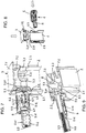
- a mounting set fixed to an upper portion of a hollow section bar of a mounting frame and in an unlocked state, in a perspective side view;
- Fig. 2
- the fixing set according to
Fig. 1 in a corresponding perspective side view, however, wherein parts of the attachment set and the upper portion of the hollow profile bar are shown vertically sectioned; - Fig. 3
- the fixing set according to
Fig. 1 in a corresponding perspective side view, wherein the fastening set is in a locked state; - Fig. 4
- the fixing set according to
Fig. 3 in a corresponding perspective side view, however, wherein parts of the attachment set and the upper portion of the hollow profile bar are again shown in vertical section; - FIGS. 5 and 6
- a fastening device according to the invention in a perspective side view, in an unlocked and a locked state, wherein axially displaceable parts of the device are each shown axially cut;
- Fig. 7
- the device off
Fig. 5 attached to an upper portion of a hollow profile bar that is vertically cut, without threaded rod, in a perspective side view; - Fig. 8
- the parts off
Fig. 7 in an exploded view; and - Fig. 9
- the parts from the
FIGS. 7 and 8 cut horizontally, in another perspective view.
Die in der Zeichnung gezeigte erfindungsgemäße Vorrichtung 1 dient zum Befestigen eines Sanitärgegenstandes, beispielsweise eines Waschbeckens oder eines Montagegestells zur Halterung eines Sanitärgegenstandes, an einer Gebäudewand oder an einem Träger. Die erfindungsgemäße Befestigungsvorrichtung 1 ist insbesondere in den
Von dem Montagegestell ist in der Zeichnung lediglich ein oberer Abschnitt einer vertikal auszurichtenden Hohlprofilstange 2 gezeigt. Das Montagegestell weist üblicherweise mindestens zwei vertikal auszurichtende Hohlprofilstangen 2 auf, die durch einen oder mehrere Querträger (Querstreben) miteinander verbunden sind. Die Hohlprofilstangen 2 können beispielsweise aus Vierkantrohren oder aus offenen Profilstangen, die im Querschnitt im Wesentlichen C-förmig ausgebildet sind, bestehen. Des Weiteren können die Hohlprofilstangen 2 an mindestens zwei ihrer benachbarten Längskanten ausgebildete Längsnuten 2.1, 2.2 aufweisen, die dem formschlüssigen Anklemmen eines Verbinders zum Befestigen einer oder mehrerer weiterer Hohlprofilstangen dienen.Of the mounting frame, only an upper portion of a vertically aligned
Das Befestigungsset 1 ist aus einem an einer Gebäudewand zu befestigenden Befestigungsteil 3, einem bolzen- oder stangenförmigen Schraubelement 4, einem mit dem Montagegestell lösbar verbindbaren, kanalförmigen Verbindungsteil 5 und einem axial zur Längsachse des Schraubelements 4 bewegbaren Riegel 6 zusammengesetzt. Das Schraubelement 4 ist als Gewindestange ausgeführt. Sie besitzt zumindest über einen Längenabschnitt ein Außengewinde 4.1.The fastening set 1 is composed of a
Jeweils am oberen Ende der vertikal auszurichtenden Hohlprofilstangen 2 des Montagegestells sind zwei gegenüberliegende Durchgangsöffnungen (Löcher) 2.3, 2.4 eingearbeitet, die der Befestigung des kanalförmigen Verbindungsteils 5 dienen. Das Verbindungsteil 5 weist hierzu einen Befestigungsabschnitt 5.1 auf, über den es formschlüssig mit dem Montagegestell verbindbar ist. Vorzugsweise ist der Befestigungsabschnitt 5.1 derart ausgebildet, dass über ihn das Verbindungsteil 5 mittels eines Steckteils 7 am Montagegestell axial festlegbar ist. Beispielsweise weist der Befestigungsabschnitt hierzu einen Spalt 5.2 auf, in den ein Abschnitt des Montagegestells, nämlich ein die Durchgangsöffnung 2.4 begrenzender Abschnitt der Hohlprofilstange 2 einbringbar ist. Der Spalt 5.2 ist durch zwei an dem kanalförmigen Verbindungsteil angeformte Flansche 5.3, 5.4 definiert.In each case at the upper end of the vertically aligned hollow profile bars 2 of the mounting frame two opposite through holes (holes) 2.3, 2.4 are incorporated, which serve the attachment of the channel-shaped connecting
Der am stirnseitigen Ende des kanalförmigen Verbindungsteils 5 angeordnete Flansch 5.3 ist vorzugsweise kreisförmig oder zylindrisch ausgebildet. Der dazu axial beabstandete Flansch 5.4 ist nicht-kreisförmig, beispielsweise oval ausgebildet. Der Spalt 5.2 oder axiale Abstand zwischen den beiden Flanschen 5.3, 5.4 entspricht der Wandstärke oder ist etwas größer als die Wandstärke der Hohlprofilstange 2.The arranged at the front end of the channel-shaped connecting
Die beiden Durchgangsöffnungen 2.3, 2.4 der Hohlprofilstange 2 sind ebenfalls unterschiedlich ausgebildet. Die Öffnung 2.3, die in der dem Raum zugewandten Hohlprofilstangenseite eingearbeitet ist, ist vorzugsweise als kreisrundes Loch ausgeführt, während die andere Öffnung 2.4, die in der der Gebäudewand zugewandten Hohlprofilstangenseite eingearbeitet ist, als ovales Loch ausgeführt ist. Der kleinste Innenweite des ovalen Lochs 2.4 ist deutlich kleiner als der Durchmesser der anderen Öffnung 2.3 und auch deutlich kleiner als der Außendurchmesser des kreisförmigen Flansches 5.3 des kanalförmigen Verbindungsteils. Die Durchgangsöffnungen 2.3, 2.4 sind so bemessen, dass das Verbindungsteil 5 über die kreisförmige Öffnung 2.3 hindurch soweit in die ovale Öffnung 2.4 eingeführt werden kann, bis der kreisförmige Flansch 5.3 an der Innenseite der die ovale Öffnung 2.4 aufweisenden Wandung 2.5 der Hohlprofilstange 2 anschlägt (vgl.
Anschließend wird das Steckteil 7 von oben in die Hohlprofilstange 2 eingesteckt, um das kanalförmige Verbindungsteil 5 am Montagegestell axial festzulegen. Das Steckteil 7 ist vorzugsweise als Stopfen oder Kappe ausgebildet, um die obere Endöffnung 2.6 der Hohlprofilstange 2 zu verschließen. Das Steckteil 7, das auch als Verschlusskappe bezeichnet werden kann, weist einen deckelartigen Abschnitt 7.1 auf, dessen Oberseite vorzugsweise im Wesentlichen eben ausgebildet ist. An der Unterseite des deckelartigen Abschnitts 7.1 sind in die Hohlprofilstange 2 einsteckbare Vorsprünge 7.2, 7.3 ausgebildet. Einer dieser Vorsprünge ist beispielsweise in Form eines umlaufenden Kragens 7.2 ausgebildet, der vier im Wesentlichen rechtwinklig zueinander angeordnete Seitenabschnitte aufweist, wobei der jeweilige Seitenabschnitt eine konkave Einbuchtung 7.21 aufweist. In eine dieser Einbuchtungen 7.21 greift teilweise der kreisförmige Flansch 5.3 des Verbindungsteils 5 ein. Die Seitenabschnitte des Kragens 7.2 verlaufen im montierten Zustand der Verschlusskappe 7 nahe oder dicht an den Innenseiten der Hohlprofilstange 2 (vgl.
Die anderen Vorsprünge 7.3 der Kappe 7 sind innerhalb des Kragens 7.2 angeordnet und ragen deutlich tiefer in die Hohlprofilstange 2 als der kragenförmige Vorsprung 7.2. Die Vorsprünge 7.3 weisen jeweils ein im Wesentlichen L- oder winkelförmiges Querschnittprofil auf. Sie begrenzen einen kreuzförmigen Durchgang (vgl.
Das an einer Gebäudewand anzubringende Befestigungsteil 3 weist ein Gewindeloch 3.1 auf, in welches das Schraubelement 4 einschraubbar ist. Das Befestigungsteil 3 besitzt einen plattenförmigen Abschnitt 3.2 mit einer Durchgangsöffnung 3.3 zum Anbringen einer Befestigungsschraube (nicht gezeigt), wobei der Kopf der Schraube im montierten Zustand vorzugsweise mit einer Unterlegscheibe an der Innenseite des Befestigungsteils 3 anliegt. Die Durchgangsöffnung 3.3 ist vorzugsweise als Langloch ausgebildet. Des Weiteren weist das Befestigungsteil 3 von dem plattenförmigen Abschnitt abstehende Stege 3.4 auf. Die Stege 3.4 schließen einen das Gewindeloch 3.1 zum Einschrauben des Schraubelements 4 aufweisenden Schraubdom 3.5 ein bzw. sind an den Schraubdom 3.5 angeformt. Das dem Montagegestell zugewandte Ende des Schraubdoms 3.5 sowie die dem Montagegestell zugewandten Kanten der Stege 3.4 schließen vorzugsweise im Wesentlichen flächenbündig zueinander ab.The mounting
Das Schraubelement (Gewindestange) 4 ist in dem kanalförmigen Verbindungsteil 5 axial verschiebbar geführt. Das Verbindungsteil 5 weist einen hülsenförmigen Abschnitt 5.5 auf, an den sich axial ein rinnenförmiger Abschnitt 5.6 anschließt. Die Flansche 5.3, 5.4 sind an dem hülsenförmigen Abschnitt 5.5 angeordnet. Das Verbindungsteil 5 hat entlang seines hülsenförmigen Abschnitts 5.5 eine ovale Innenquerschnittsfläche. Die Innenseite des hülsenförmigen Abschnitts 5.5 ist vorzugsweise glatt oder im Wesentlichen glatt ausgebildet. Die kleinste Innenweite der ovalen Innenquerschnittsfläche des hülsenförmigen Abschnitts 5.4 ist größer als der Außendurchmesser des Gewindes 4.1 des Schraubelements 4. Der rinnenförmige Abschnitt 5.6 des Verbindungsteils weist innenseitig ein rinnenförmiges Innenteilgewinde 5.7 auf (vgl.
Auf dem kanalförmigen Verbindungsteil 5 sitzt der als Schieber ausgebildete Riegel 6. Er ist axial zur Längsachse des Verbindungsteils 5 aus einer Nicht-Kontaktstellung in eine Kontaktstellung und umgekehrt verschiebbar und weist einen dem bolzen- oder stangenförmigen Schraubelement 4 zugewandten Kontaktabschnitt 6.1 auf, der in der Kontaktstellung am Außengewinde 4.1 des Schraubelements anliegt. Der Kontaktabschnitt 6.1 des Riegels ist als Vorsprung ausgebildet. Die Längsöffnung 5.61 des rinnenförmigen Abschnitts 5.6 des Verbindungsteils definiert eine Axialführung für den Riegel 6, wobei der Kontaktabschnitt 6.1 des Riegels in der Verriegelungsstellung in der Längsöffnung 5.61 aufgenommen ist.He is axially displaceable to the longitudinal axis of the connecting
In den
Der Riegel 6 weist innenseitig eine den Gleitkanten oder Gleitflächen 5.81, 5.10 zugeordnete Gleitkante oder Gleitfläche 6.8 auf, die ebenfalls schräg zur Längsachse des Riegels 6 bzw. des Verbindungsteils 5 verläuft.On the inside, the
Des Weiteren besitzt das kanalförmige Verbindungsteil 5 an seiner Außenseite axial voneinander beabstandete Vertiefungen 5.11, 5.12, denen ein mit dem Riegel 6 verbundenes Rastelement 6.2 zugeordnet ist. Das Rastelement 6.2 ist beispielsweise in Form einer federelastischen Rastlasche ausgebildet. Es rastet in zwei verschiedenen Positionen des Riegels 6 relativ zu dem Verbindungsteil 5 in eine der beiden Vertiefungen 5.11, 5.12 ein. Die Vertiefungen 5.11, 5.12 sind einerseits einem Entriegelungszustand und andererseits einem Verriegelungszustand zugeordnet. Die möglichen Bewegungsrichtungen des Riegels 6 sind durch eingeprägte oder aufgedruckte Doppelpfeile 6.3 markiert. Zudem ist der Riegel 6 mit zwei Symbolen 6.4, 6.5 versehen, welche ein geschlossenes und ein geöffnetes Bügelschloss symbolisieren und in Kombination mit den Doppelpfeilen 6.3 die Verschieberichtung zur Einstellung des Entriegelungszustandes bzw. des Verriegelungszustandes anzeigen. Darüber hinaus weist der Riegel 6 auf seiner Außenfläche zwei entgegengesetzt angeordnete Rippenflächen 6.6, 6.7 auf, die als rutschhemmende Griffflächen die manuelle, werkzeuglose Verschiebung des Riegels 6 erleichtern.Furthermore, the channel-shaped connecting
In der Verriegelungsstellung bildet der Riegel 6 zusammen mit dem kanalförmigen Verbindungsteil 5 eine (zweiteilige) Mutter. In dieser Stellung kann der Riegel 6 zusammen mit dem Verbindungsteil 5 um die Längsachse des Schraubelements 4 gedreht werden und damit eine Feineinstellung der Montagetiefe des Montagegestells vorgenommen werden. Für eine schnelle Grobeinstellung der Montagetiefe wird der Riegel 6 in die Entriegelungsstellung geschoben und dabei der Eingriff des Innenteilgewindes 5.7 des Verbindungsteils 5 in das Außengewinde 4.1 des Schraubelements 4 durch eine Radialbewegung des Verbindungsteils 5 gelöst. Sodann können das Schraubelement (Gewindestange) 4 und das kanalförmige Verbindungsteil 5 relativ zueinander axial verschoben und damit die Montagetiefe des Montagegestells schnell und grob eingestellt werden. Danach werden das Innenteilgewinde 5.7 des Verbindungsteils und das Außengewinde 4.1 des Schraubelements durch eine umgekehrte Radialbewegung des Verbindungsteils 5 wieder in Eingriff gebracht und durch Verschiebung des Riegels 6 in die Verriegelungsstellung verriegelt. Bei Bedarf kann dann durch Drehen des Riegels 6 zusammen mit dem damit verriegelten Verbindungsteil 5 um die Längsachse des Schraubelements 4 eine Feineinstellung der Montagetiefe vorgenommen werden.In the locked position, the
Die Ausführung der Erfindung ist nicht auf die in der Zeichnung dargestellten Ausführungsbeispiele beschränkt. Vielmehr sind verschiedene Modifikationen möglich, die auch bei einer von den gezeigten Beispielen abweichenden Gestaltung von der in den Ansprüchen angegebenen Erfindung Gebrauch machen. So kann beispielsweise der Flansch 5.4 des Verbindungsteils 5 auch weggelassen werden.The embodiment of the invention is not limited to the embodiments shown in the drawing. On the contrary, various modifications are possible which make use of the invention disclosed in the claims even if the design deviates from the examples shown. For example, the flange 5.4 of the connecting
Claims (12)
Priority Applications (1)
| Application Number | Priority Date | Filing Date | Title |
|---|---|---|---|
| PL18160256T PL3404151T3 (en) | 2017-05-17 | 2018-03-06 | Device for fixing a sanitary object and use of same |
Applications Claiming Priority (1)
| Application Number | Priority Date | Filing Date | Title |
|---|---|---|---|
| DE102017110764.9A DE102017110764A1 (en) | 2017-05-17 | 2017-05-17 | Device for fixing a sanitary object and use of such a device |
Publications (2)
| Publication Number | Publication Date |
|---|---|
| EP3404151A1 true EP3404151A1 (en) | 2018-11-21 |
| EP3404151B1 EP3404151B1 (en) | 2021-02-24 |
Family
ID=61581011
Family Applications (1)
| Application Number | Title | Priority Date | Filing Date |
|---|---|---|---|
| EP18160256.6A Active EP3404151B1 (en) | 2017-05-17 | 2018-03-06 | Device for fixing a sanitary object and use of same |
Country Status (5)
| Country | Link |
|---|---|
| EP (1) | EP3404151B1 (en) |
| DE (1) | DE102017110764A1 (en) |
| DK (1) | DK3404151T3 (en) |
| ES (1) | ES2861748T3 (en) |
| PL (1) | PL3404151T3 (en) |
Cited By (5)
| Publication number | Priority date | Publication date | Assignee | Title |
|---|---|---|---|---|
| EP3441536A1 (en) * | 2017-08-11 | 2019-02-13 | GROHEDAL Sanitärsysteme GmbH | Device for mounting a frame for a sanitary unit |
| EP3926185A1 (en) * | 2020-06-19 | 2021-12-22 | Geberit International AG | Wall support |
| CN114703929A (en) * | 2022-03-29 | 2022-07-05 | 厦门倍杰特科技有限公司 | Locking mechanism for wall hanging object |
| EP4039897A1 (en) | 2021-02-04 | 2022-08-10 | Geberit International AG | Wall support |
| WO2022167209A1 (en) | 2021-02-03 | 2022-08-11 | Geberit International Ag | Wall mount |
Citations (5)
| Publication number | Priority date | Publication date | Assignee | Title |
|---|---|---|---|---|
| DE20068C (en) * | A. wagner in Radevormwald | Movable nut | ||
| FR1070804A (en) * | 1952-02-20 | 1954-08-17 | Boehler & Co Ag Geb | Quick screw clamp |
| DE19958627A1 (en) * | 1999-12-03 | 2000-04-27 | Eduard Janssen | Spindle locking nut has widened bore hole for immediate positioning against locking flange without rotation over entire spindle length |
| FR2874040A1 (en) * | 2004-08-06 | 2006-02-10 | L R Etanco Soc Par Actions Sim | Panel fixation device for forming e.g. wall cladding, has lever passing from unlocked position to locked position in which cam section of lever exerts, on threaded rod, force to be applied on counter-support unit of jumper |
| EP1990547A2 (en) * | 2007-05-09 | 2008-11-12 | Erico International Corporation | Structural beam clamps and connectors |
Family Cites Families (1)
| Publication number | Priority date | Publication date | Assignee | Title |
|---|---|---|---|---|
| PL203127B1 (en) | 2001-05-21 | 2009-08-31 | Geberit Technik Ag | Wall mounted bracket for a saniatry appliance supporting frame |
-
2017
- 2017-05-17 DE DE102017110764.9A patent/DE102017110764A1/en not_active Withdrawn
-
2018
- 2018-03-06 DK DK18160256.6T patent/DK3404151T3/en active
- 2018-03-06 PL PL18160256T patent/PL3404151T3/en unknown
- 2018-03-06 ES ES18160256T patent/ES2861748T3/en active Active
- 2018-03-06 EP EP18160256.6A patent/EP3404151B1/en active Active
Patent Citations (5)
| Publication number | Priority date | Publication date | Assignee | Title |
|---|---|---|---|---|
| DE20068C (en) * | A. wagner in Radevormwald | Movable nut | ||
| FR1070804A (en) * | 1952-02-20 | 1954-08-17 | Boehler & Co Ag Geb | Quick screw clamp |
| DE19958627A1 (en) * | 1999-12-03 | 2000-04-27 | Eduard Janssen | Spindle locking nut has widened bore hole for immediate positioning against locking flange without rotation over entire spindle length |
| FR2874040A1 (en) * | 2004-08-06 | 2006-02-10 | L R Etanco Soc Par Actions Sim | Panel fixation device for forming e.g. wall cladding, has lever passing from unlocked position to locked position in which cam section of lever exerts, on threaded rod, force to be applied on counter-support unit of jumper |
| EP1990547A2 (en) * | 2007-05-09 | 2008-11-12 | Erico International Corporation | Structural beam clamps and connectors |
Cited By (6)
| Publication number | Priority date | Publication date | Assignee | Title |
|---|---|---|---|---|
| EP3441536A1 (en) * | 2017-08-11 | 2019-02-13 | GROHEDAL Sanitärsysteme GmbH | Device for mounting a frame for a sanitary unit |
| EP3926185A1 (en) * | 2020-06-19 | 2021-12-22 | Geberit International AG | Wall support |
| WO2022167209A1 (en) | 2021-02-03 | 2022-08-11 | Geberit International Ag | Wall mount |
| EP4039897A1 (en) | 2021-02-04 | 2022-08-10 | Geberit International AG | Wall support |
| CN114703929A (en) * | 2022-03-29 | 2022-07-05 | 厦门倍杰特科技有限公司 | Locking mechanism for wall hanging object |
| CN114703929B (en) * | 2022-03-29 | 2023-05-30 | 厦门倍杰特科技有限公司 | Locking mechanism for wall-hung object |
Also Published As
| Publication number | Publication date |
|---|---|
| DE102017110764A1 (en) | 2018-11-22 |
| PL3404151T3 (en) | 2021-06-14 |
| DK3404151T3 (en) | 2021-04-26 |
| ES2861748T3 (en) | 2021-10-06 |
| EP3404151B1 (en) | 2021-02-24 |
Similar Documents
| Publication | Publication Date | Title |
|---|---|---|
| EP3404151B1 (en) | Device for fixing a sanitary object and use of same | |
| DE60106980T2 (en) | Lever operated lock for telescopic rod | |
| DE102014110638A1 (en) | Quick-mount and removable screw socket | |
| EP2055867A1 (en) | Grip with fastening insert | |
| EP3760076A1 (en) | Connecting pin for pieces of furniture | |
| EP3180527B1 (en) | Fastening device and fastening assembly, in particular for fastening a sanitary object | |
| EP1870526A1 (en) | Sanitary fixture | |
| EP3211145A1 (en) | Fixing device for a sanitary fixture suspended on the wall | |
| EP3486420B1 (en) | Method for positioning a window or a door | |
| EP0521490B1 (en) | Arrangement of two construction elements telescopically connected together | |
| EP3586415B1 (en) | Plug coupling with strain relief for a connecting cable | |
| EP3625417A1 (en) | Length-adjustable control arm | |
| EP2985477A1 (en) | Fastening device and fastening assembly, in particular for fastening a sanitary object | |
| EP3404153B1 (en) | Fixing set for fixing a mounting frame for sanitary objects and use of such a fixing set | |
| EP0555633B1 (en) | Door handle fitting | |
| EP3404152B1 (en) | Fixing set for fixing a mounting frame for sanitary objects and use of such a fixing set | |
| DE202016101091U1 (en) | door lock | |
| DE60038654T2 (en) | Clamping bracket for support and connection elements | |
| EP2574799A1 (en) | Telescopic connection assembly | |
| DE102005000195A1 (en) | Fitting for window or door, has guide rail and sliding component which is guided in undercut profile groove of guide rail such that it is displaced longitudinally along adjustment axis | |
| EP4047219B1 (en) | Assembly unit with at least one mounting rail and at least one retaining clip | |
| DE19545945C1 (en) | Water tap with removable tap body | |
| EP1457607A2 (en) | Device for fixing a pipe | |
| EP3535824B1 (en) | Busbar holder and corresponding assembly | |
| EP3269903B1 (en) | Rosette fitting for pushers for doors or windows |
Legal Events
| Date | Code | Title | Description |
|---|---|---|---|
| PUAI | Public reference made under article 153(3) epc to a published international application that has entered the european phase |
Free format text: ORIGINAL CODE: 0009012 |
|
| STAA | Information on the status of an ep patent application or granted ep patent |
Free format text: STATUS: THE APPLICATION HAS BEEN PUBLISHED |
|
| AK | Designated contracting states |
Kind code of ref document: A1 Designated state(s): AL AT BE BG CH CY CZ DE DK EE ES FI FR GB GR HR HU IE IS IT LI LT LU LV MC MK MT NL NO PL PT RO RS SE SI SK SM TR |
|
| AX | Request for extension of the european patent |
Extension state: BA ME |
|
| STAA | Information on the status of an ep patent application or granted ep patent |
Free format text: STATUS: REQUEST FOR EXAMINATION WAS MADE |
|
| 17P | Request for examination filed |
Effective date: 20190515 |
|
| RBV | Designated contracting states (corrected) |
Designated state(s): AL AT BE BG CH CY CZ DE DK EE ES FI FR GB GR HR HU IE IS IT LI LT LU LV MC MK MT NL NO PL PT RO RS SE SI SK SM TR |
|
| GRAP | Despatch of communication of intention to grant a patent |
Free format text: ORIGINAL CODE: EPIDOSNIGR1 |
|
| STAA | Information on the status of an ep patent application or granted ep patent |
Free format text: STATUS: GRANT OF PATENT IS INTENDED |
|
| INTG | Intention to grant announced |
Effective date: 20201118 |
|
| GRAS | Grant fee paid |
Free format text: ORIGINAL CODE: EPIDOSNIGR3 |
|
| GRAA | (expected) grant |
Free format text: ORIGINAL CODE: 0009210 |
|
| STAA | Information on the status of an ep patent application or granted ep patent |
Free format text: STATUS: THE PATENT HAS BEEN GRANTED |
|
| AK | Designated contracting states |
Kind code of ref document: B1 Designated state(s): AL AT BE BG CH CY CZ DE DK EE ES FI FR GB GR HR HU IE IS IT LI LT LU LV MC MK MT NL NO PL PT RO RS SE SI SK SM TR |
|
| REG | Reference to a national code |
Ref country code: CH Ref legal event code: EP |
|
| REG | Reference to a national code |
Ref country code: DE Ref legal event code: R096 Ref document number: 502018003950 Country of ref document: DE |
|
| REG | Reference to a national code |
Ref country code: AT Ref legal event code: REF Ref document number: 1364595 Country of ref document: AT Kind code of ref document: T Effective date: 20210315 Ref country code: CH Ref legal event code: NV Representative=s name: SCHMAUDER AND PARTNER AG PATENT- UND MARKENANW, CH |
|
| REG | Reference to a national code |
Ref country code: IE Ref legal event code: FG4D Free format text: LANGUAGE OF EP DOCUMENT: GERMAN |
|
| REG | Reference to a national code |
Ref country code: NL Ref legal event code: FP |
|
| REG | Reference to a national code |
Ref country code: DK Ref legal event code: T3 Effective date: 20210420 |
|
| REG | Reference to a national code |
Ref country code: LT Ref legal event code: MG9D |
|
| PG25 | Lapsed in a contracting state [announced via postgrant information from national office to epo] |
Ref country code: BG Free format text: LAPSE BECAUSE OF FAILURE TO SUBMIT A TRANSLATION OF THE DESCRIPTION OR TO PAY THE FEE WITHIN THE PRESCRIBED TIME-LIMIT Effective date: 20210524 Ref country code: LT Free format text: LAPSE BECAUSE OF FAILURE TO SUBMIT A TRANSLATION OF THE DESCRIPTION OR TO PAY THE FEE WITHIN THE PRESCRIBED TIME-LIMIT Effective date: 20210224 Ref country code: FI Free format text: LAPSE BECAUSE OF FAILURE TO SUBMIT A TRANSLATION OF THE DESCRIPTION OR TO PAY THE FEE WITHIN THE PRESCRIBED TIME-LIMIT Effective date: 20210224 Ref country code: HR Free format text: LAPSE BECAUSE OF FAILURE TO SUBMIT A TRANSLATION OF THE DESCRIPTION OR TO PAY THE FEE WITHIN THE PRESCRIBED TIME-LIMIT Effective date: 20210224 Ref country code: GR Free format text: LAPSE BECAUSE OF FAILURE TO SUBMIT A TRANSLATION OF THE DESCRIPTION OR TO PAY THE FEE WITHIN THE PRESCRIBED TIME-LIMIT Effective date: 20210525 Ref country code: PT Free format text: LAPSE BECAUSE OF FAILURE TO SUBMIT A TRANSLATION OF THE DESCRIPTION OR TO PAY THE FEE WITHIN THE PRESCRIBED TIME-LIMIT Effective date: 20210624 Ref country code: NO Free format text: LAPSE BECAUSE OF FAILURE TO SUBMIT A TRANSLATION OF THE DESCRIPTION OR TO PAY THE FEE WITHIN THE PRESCRIBED TIME-LIMIT Effective date: 20210524 |
|
| PG25 | Lapsed in a contracting state [announced via postgrant information from national office to epo] |
Ref country code: RS Free format text: LAPSE BECAUSE OF FAILURE TO SUBMIT A TRANSLATION OF THE DESCRIPTION OR TO PAY THE FEE WITHIN THE PRESCRIBED TIME-LIMIT Effective date: 20210224 Ref country code: LV Free format text: LAPSE BECAUSE OF FAILURE TO SUBMIT A TRANSLATION OF THE DESCRIPTION OR TO PAY THE FEE WITHIN THE PRESCRIBED TIME-LIMIT Effective date: 20210224 Ref country code: SE Free format text: LAPSE BECAUSE OF FAILURE TO SUBMIT A TRANSLATION OF THE DESCRIPTION OR TO PAY THE FEE WITHIN THE PRESCRIBED TIME-LIMIT Effective date: 20210224 |
|
| PG25 | Lapsed in a contracting state [announced via postgrant information from national office to epo] |
Ref country code: IS Free format text: LAPSE BECAUSE OF FAILURE TO SUBMIT A TRANSLATION OF THE DESCRIPTION OR TO PAY THE FEE WITHIN THE PRESCRIBED TIME-LIMIT Effective date: 20210624 |
|
| REG | Reference to a national code |
Ref country code: ES Ref legal event code: FG2A Ref document number: 2861748 Country of ref document: ES Kind code of ref document: T3 Effective date: 20211006 |
|
| PG25 | Lapsed in a contracting state [announced via postgrant information from national office to epo] |
Ref country code: SM Free format text: LAPSE BECAUSE OF FAILURE TO SUBMIT A TRANSLATION OF THE DESCRIPTION OR TO PAY THE FEE WITHIN THE PRESCRIBED TIME-LIMIT Effective date: 20210224 Ref country code: EE Free format text: LAPSE BECAUSE OF FAILURE TO SUBMIT A TRANSLATION OF THE DESCRIPTION OR TO PAY THE FEE WITHIN THE PRESCRIBED TIME-LIMIT Effective date: 20210224 Ref country code: CZ Free format text: LAPSE BECAUSE OF FAILURE TO SUBMIT A TRANSLATION OF THE DESCRIPTION OR TO PAY THE FEE WITHIN THE PRESCRIBED TIME-LIMIT Effective date: 20210224 |
|
| REG | Reference to a national code |
Ref country code: DE Ref legal event code: R097 Ref document number: 502018003950 Country of ref document: DE |
|
| PG25 | Lapsed in a contracting state [announced via postgrant information from national office to epo] |
Ref country code: RO Free format text: LAPSE BECAUSE OF FAILURE TO SUBMIT A TRANSLATION OF THE DESCRIPTION OR TO PAY THE FEE WITHIN THE PRESCRIBED TIME-LIMIT Effective date: 20210224 Ref country code: SK Free format text: LAPSE BECAUSE OF FAILURE TO SUBMIT A TRANSLATION OF THE DESCRIPTION OR TO PAY THE FEE WITHIN THE PRESCRIBED TIME-LIMIT Effective date: 20210224 Ref country code: MC Free format text: LAPSE BECAUSE OF FAILURE TO SUBMIT A TRANSLATION OF THE DESCRIPTION OR TO PAY THE FEE WITHIN THE PRESCRIBED TIME-LIMIT Effective date: 20210224 |
|
| PLBE | No opposition filed within time limit |
Free format text: ORIGINAL CODE: 0009261 |
|
| STAA | Information on the status of an ep patent application or granted ep patent |
Free format text: STATUS: NO OPPOSITION FILED WITHIN TIME LIMIT |
|
| PG25 | Lapsed in a contracting state [announced via postgrant information from national office to epo] |
Ref country code: LU Free format text: LAPSE BECAUSE OF NON-PAYMENT OF DUE FEES Effective date: 20210306 Ref country code: AL Free format text: LAPSE BECAUSE OF FAILURE TO SUBMIT A TRANSLATION OF THE DESCRIPTION OR TO PAY THE FEE WITHIN THE PRESCRIBED TIME-LIMIT Effective date: 20210224 Ref country code: IE Free format text: LAPSE BECAUSE OF NON-PAYMENT OF DUE FEES Effective date: 20210306 |
|
| 26N | No opposition filed |
Effective date: 20211125 |
|
| PG25 | Lapsed in a contracting state [announced via postgrant information from national office to epo] |
Ref country code: SI Free format text: LAPSE BECAUSE OF FAILURE TO SUBMIT A TRANSLATION OF THE DESCRIPTION OR TO PAY THE FEE WITHIN THE PRESCRIBED TIME-LIMIT Effective date: 20210224 |
|
| PG25 | Lapsed in a contracting state [announced via postgrant information from national office to epo] |
Ref country code: IS Free format text: LAPSE BECAUSE OF FAILURE TO SUBMIT A TRANSLATION OF THE DESCRIPTION OR TO PAY THE FEE WITHIN THE PRESCRIBED TIME-LIMIT Effective date: 20210624 |
|
| PGFP | Annual fee paid to national office [announced via postgrant information from national office to epo] |
Ref country code: FR Payment date: 20230323 Year of fee payment: 6 Ref country code: DK Payment date: 20230329 Year of fee payment: 6 Ref country code: AT Payment date: 20230327 Year of fee payment: 6 |
|
| PGFP | Annual fee paid to national office [announced via postgrant information from national office to epo] |
Ref country code: PL Payment date: 20230228 Year of fee payment: 6 Ref country code: IT Payment date: 20230323 Year of fee payment: 6 Ref country code: GB Payment date: 20230322 Year of fee payment: 6 Ref country code: DE Payment date: 20230322 Year of fee payment: 6 Ref country code: BE Payment date: 20230322 Year of fee payment: 6 |
|
| PG25 | Lapsed in a contracting state [announced via postgrant information from national office to epo] |
Ref country code: CY Free format text: LAPSE BECAUSE OF FAILURE TO SUBMIT A TRANSLATION OF THE DESCRIPTION OR TO PAY THE FEE WITHIN THE PRESCRIBED TIME-LIMIT Effective date: 20210224 |
|
| PGFP | Annual fee paid to national office [announced via postgrant information from national office to epo] |
Ref country code: NL Payment date: 20230322 Year of fee payment: 6 |
|
| PG25 | Lapsed in a contracting state [announced via postgrant information from national office to epo] |
Ref country code: HU Free format text: LAPSE BECAUSE OF FAILURE TO SUBMIT A TRANSLATION OF THE DESCRIPTION OR TO PAY THE FEE WITHIN THE PRESCRIBED TIME-LIMIT; INVALID AB INITIO Effective date: 20180306 |
|
| PGFP | Annual fee paid to national office [announced via postgrant information from national office to epo] |
Ref country code: ES Payment date: 20230421 Year of fee payment: 6 Ref country code: CH Payment date: 20230401 Year of fee payment: 6 |
|
| PGFP | Annual fee paid to national office [announced via postgrant information from national office to epo] |
Ref country code: NL Payment date: 20240321 Year of fee payment: 7 |
|
| PGFP | Annual fee paid to national office [announced via postgrant information from national office to epo] |
Ref country code: AT Payment date: 20240322 Year of fee payment: 7 |