EP3402646B1 - Procédé et dispositif de fabrication d'un tuyau en matière thermoplastique par moulage par injection - Google Patents
Procédé et dispositif de fabrication d'un tuyau en matière thermoplastique par moulage par injection Download PDFInfo
- Publication number
- EP3402646B1 EP3402646B1 EP17700639.2A EP17700639A EP3402646B1 EP 3402646 B1 EP3402646 B1 EP 3402646B1 EP 17700639 A EP17700639 A EP 17700639A EP 3402646 B1 EP3402646 B1 EP 3402646B1
- Authority
- EP
- European Patent Office
- Prior art keywords
- article
- nozzle body
- cavity
- projectile
- injection
- Prior art date
- Legal status (The legal status is an assumption and is not a legal conclusion. Google has not performed a legal analysis and makes no representation as to the accuracy of the status listed.)
- Active
Links
Images

Classifications
-
- B—PERFORMING OPERATIONS; TRANSPORTING
- B29—WORKING OF PLASTICS; WORKING OF SUBSTANCES IN A PLASTIC STATE IN GENERAL
- B29C—SHAPING OR JOINING OF PLASTICS; SHAPING OF MATERIAL IN A PLASTIC STATE, NOT OTHERWISE PROVIDED FOR; AFTER-TREATMENT OF THE SHAPED PRODUCTS, e.g. REPAIRING
- B29C45/00—Injection moulding, i.e. forcing the required volume of moulding material through a nozzle into a closed mould; Apparatus therefor
- B29C45/14—Injection moulding, i.e. forcing the required volume of moulding material through a nozzle into a closed mould; Apparatus therefor incorporating preformed parts or layers, e.g. injection moulding around inserts or for coating articles
- B29C45/14065—Positioning or centering articles in the mould
-
- B—PERFORMING OPERATIONS; TRANSPORTING
- B29—WORKING OF PLASTICS; WORKING OF SUBSTANCES IN A PLASTIC STATE IN GENERAL
- B29B—PREPARATION OR PRETREATMENT OF THE MATERIAL TO BE SHAPED; MAKING GRANULES OR PREFORMS; RECOVERY OF PLASTICS OR OTHER CONSTITUENTS OF WASTE MATERIAL CONTAINING PLASTICS
- B29B11/00—Making preforms
- B29B11/06—Making preforms by moulding the material
- B29B11/08—Injection moulding
-
- B—PERFORMING OPERATIONS; TRANSPORTING
- B29—WORKING OF PLASTICS; WORKING OF SUBSTANCES IN A PLASTIC STATE IN GENERAL
- B29C—SHAPING OR JOINING OF PLASTICS; SHAPING OF MATERIAL IN A PLASTIC STATE, NOT OTHERWISE PROVIDED FOR; AFTER-TREATMENT OF THE SHAPED PRODUCTS, e.g. REPAIRING
- B29C45/00—Injection moulding, i.e. forcing the required volume of moulding material through a nozzle into a closed mould; Apparatus therefor
- B29C45/14—Injection moulding, i.e. forcing the required volume of moulding material through a nozzle into a closed mould; Apparatus therefor incorporating preformed parts or layers, e.g. injection moulding around inserts or for coating articles
- B29C45/14819—Injection moulding, i.e. forcing the required volume of moulding material through a nozzle into a closed mould; Apparatus therefor incorporating preformed parts or layers, e.g. injection moulding around inserts or for coating articles the inserts being completely encapsulated
-
- B—PERFORMING OPERATIONS; TRANSPORTING
- B29—WORKING OF PLASTICS; WORKING OF SUBSTANCES IN A PLASTIC STATE IN GENERAL
- B29C—SHAPING OR JOINING OF PLASTICS; SHAPING OF MATERIAL IN A PLASTIC STATE, NOT OTHERWISE PROVIDED FOR; AFTER-TREATMENT OF THE SHAPED PRODUCTS, e.g. REPAIRING
- B29C45/00—Injection moulding, i.e. forcing the required volume of moulding material through a nozzle into a closed mould; Apparatus therefor
- B29C45/17—Component parts, details or accessories; Auxiliary operations
- B29C45/1703—Introducing an auxiliary fluid into the mould
- B29C45/1704—Introducing an auxiliary fluid into the mould the fluid being introduced into the interior of the injected material which is still in a molten state, e.g. for producing hollow articles
-
- B—PERFORMING OPERATIONS; TRANSPORTING
- B29—WORKING OF PLASTICS; WORKING OF SUBSTANCES IN A PLASTIC STATE IN GENERAL
- B29C—SHAPING OR JOINING OF PLASTICS; SHAPING OF MATERIAL IN A PLASTIC STATE, NOT OTHERWISE PROVIDED FOR; AFTER-TREATMENT OF THE SHAPED PRODUCTS, e.g. REPAIRING
- B29C45/00—Injection moulding, i.e. forcing the required volume of moulding material through a nozzle into a closed mould; Apparatus therefor
- B29C45/17—Component parts, details or accessories; Auxiliary operations
- B29C45/1703—Introducing an auxiliary fluid into the mould
- B29C45/1734—Nozzles therefor
-
- B—PERFORMING OPERATIONS; TRANSPORTING
- B29—WORKING OF PLASTICS; WORKING OF SUBSTANCES IN A PLASTIC STATE IN GENERAL
- B29C—SHAPING OR JOINING OF PLASTICS; SHAPING OF MATERIAL IN A PLASTIC STATE, NOT OTHERWISE PROVIDED FOR; AFTER-TREATMENT OF THE SHAPED PRODUCTS, e.g. REPAIRING
- B29C45/00—Injection moulding, i.e. forcing the required volume of moulding material through a nozzle into a closed mould; Apparatus therefor
- B29C45/17—Component parts, details or accessories; Auxiliary operations
- B29C45/20—Injection nozzles
-
- B—PERFORMING OPERATIONS; TRANSPORTING
- B29—WORKING OF PLASTICS; WORKING OF SUBSTANCES IN A PLASTIC STATE IN GENERAL
- B29C—SHAPING OR JOINING OF PLASTICS; SHAPING OF MATERIAL IN A PLASTIC STATE, NOT OTHERWISE PROVIDED FOR; AFTER-TREATMENT OF THE SHAPED PRODUCTS, e.g. REPAIRING
- B29C45/00—Injection moulding, i.e. forcing the required volume of moulding material through a nozzle into a closed mould; Apparatus therefor
- B29C45/17—Component parts, details or accessories; Auxiliary operations
- B29C45/26—Moulds
- B29C45/261—Moulds having tubular mould cavities
-
- B—PERFORMING OPERATIONS; TRANSPORTING
- B29—WORKING OF PLASTICS; WORKING OF SUBSTANCES IN A PLASTIC STATE IN GENERAL
- B29C—SHAPING OR JOINING OF PLASTICS; SHAPING OF MATERIAL IN A PLASTIC STATE, NOT OTHERWISE PROVIDED FOR; AFTER-TREATMENT OF THE SHAPED PRODUCTS, e.g. REPAIRING
- B29C45/00—Injection moulding, i.e. forcing the required volume of moulding material through a nozzle into a closed mould; Apparatus therefor
- B29C2045/0087—Injection moulding, i.e. forcing the required volume of moulding material through a nozzle into a closed mould; Apparatus therefor making hollow articles using a floating core movable in the mould cavity by fluid pressure and expelling molten excess material
-
- B—PERFORMING OPERATIONS; TRANSPORTING
- B29—WORKING OF PLASTICS; WORKING OF SUBSTANCES IN A PLASTIC STATE IN GENERAL
- B29C—SHAPING OR JOINING OF PLASTICS; SHAPING OF MATERIAL IN A PLASTIC STATE, NOT OTHERWISE PROVIDED FOR; AFTER-TREATMENT OF THE SHAPED PRODUCTS, e.g. REPAIRING
- B29C2949/00—Indexing scheme relating to blow-moulding
- B29C2949/07—Preforms or parisons characterised by their configuration
- B29C2949/0715—Preforms or parisons characterised by their configuration the preform having one end closed
-
- B—PERFORMING OPERATIONS; TRANSPORTING
- B29—WORKING OF PLASTICS; WORKING OF SUBSTANCES IN A PLASTIC STATE IN GENERAL
- B29C—SHAPING OR JOINING OF PLASTICS; SHAPING OF MATERIAL IN A PLASTIC STATE, NOT OTHERWISE PROVIDED FOR; AFTER-TREATMENT OF THE SHAPED PRODUCTS, e.g. REPAIRING
- B29C2949/00—Indexing scheme relating to blow-moulding
- B29C2949/07—Preforms or parisons characterised by their configuration
- B29C2949/076—Preforms or parisons characterised by their configuration characterised by the shape
- B29C2949/0768—Preforms or parisons characterised by their configuration characterised by the shape characterised by the shape of specific parts of preform
- B29C2949/077—Preforms or parisons characterised by their configuration characterised by the shape characterised by the shape of specific parts of preform characterised by the neck
- B29C2949/0772—Closure retaining means
- B29C2949/0773—Threads
-
- B—PERFORMING OPERATIONS; TRANSPORTING
- B29—WORKING OF PLASTICS; WORKING OF SUBSTANCES IN A PLASTIC STATE IN GENERAL
- B29C—SHAPING OR JOINING OF PLASTICS; SHAPING OF MATERIAL IN A PLASTIC STATE, NOT OTHERWISE PROVIDED FOR; AFTER-TREATMENT OF THE SHAPED PRODUCTS, e.g. REPAIRING
- B29C2949/00—Indexing scheme relating to blow-moulding
- B29C2949/07—Preforms or parisons characterised by their configuration
- B29C2949/079—Auxiliary parts or inserts
-
- B—PERFORMING OPERATIONS; TRANSPORTING
- B29—WORKING OF PLASTICS; WORKING OF SUBSTANCES IN A PLASTIC STATE IN GENERAL
- B29C—SHAPING OR JOINING OF PLASTICS; SHAPING OF MATERIAL IN A PLASTIC STATE, NOT OTHERWISE PROVIDED FOR; AFTER-TREATMENT OF THE SHAPED PRODUCTS, e.g. REPAIRING
- B29C2949/00—Indexing scheme relating to blow-moulding
- B29C2949/20—Preforms or parisons whereby a specific part is made of only one component, e.g. only one layer
-
- B—PERFORMING OPERATIONS; TRANSPORTING
- B29—WORKING OF PLASTICS; WORKING OF SUBSTANCES IN A PLASTIC STATE IN GENERAL
- B29C—SHAPING OR JOINING OF PLASTICS; SHAPING OF MATERIAL IN A PLASTIC STATE, NOT OTHERWISE PROVIDED FOR; AFTER-TREATMENT OF THE SHAPED PRODUCTS, e.g. REPAIRING
- B29C45/00—Injection moulding, i.e. forcing the required volume of moulding material through a nozzle into a closed mould; Apparatus therefor
- B29C45/14—Injection moulding, i.e. forcing the required volume of moulding material through a nozzle into a closed mould; Apparatus therefor incorporating preformed parts or layers, e.g. injection moulding around inserts or for coating articles
- B29C45/1459—Coating annular articles
-
- B—PERFORMING OPERATIONS; TRANSPORTING
- B29—WORKING OF PLASTICS; WORKING OF SUBSTANCES IN A PLASTIC STATE IN GENERAL
- B29C—SHAPING OR JOINING OF PLASTICS; SHAPING OF MATERIAL IN A PLASTIC STATE, NOT OTHERWISE PROVIDED FOR; AFTER-TREATMENT OF THE SHAPED PRODUCTS, e.g. REPAIRING
- B29C49/00—Blow-moulding, i.e. blowing a preform or parison to a desired shape within a mould; Apparatus therefor
- B29C49/02—Combined blow-moulding and manufacture of the preform or the parison
- B29C49/06—Injection blow-moulding
-
- B—PERFORMING OPERATIONS; TRANSPORTING
- B29—WORKING OF PLASTICS; WORKING OF SUBSTANCES IN A PLASTIC STATE IN GENERAL
- B29K—INDEXING SCHEME ASSOCIATED WITH SUBCLASSES B29B, B29C OR B29D, RELATING TO MOULDING MATERIALS OR TO MATERIALS FOR MOULDS, REINFORCEMENTS, FILLERS OR PREFORMED PARTS, e.g. INSERTS
- B29K2101/00—Use of unspecified macromolecular compounds as moulding material
- B29K2101/12—Thermoplastic materials
-
- B—PERFORMING OPERATIONS; TRANSPORTING
- B29—WORKING OF PLASTICS; WORKING OF SUBSTANCES IN A PLASTIC STATE IN GENERAL
- B29K—INDEXING SCHEME ASSOCIATED WITH SUBCLASSES B29B, B29C OR B29D, RELATING TO MOULDING MATERIALS OR TO MATERIALS FOR MOULDS, REINFORCEMENTS, FILLERS OR PREFORMED PARTS, e.g. INSERTS
- B29K2905/00—Use of metals, their alloys or their compounds, as mould material
-
- B—PERFORMING OPERATIONS; TRANSPORTING
- B29—WORKING OF PLASTICS; WORKING OF SUBSTANCES IN A PLASTIC STATE IN GENERAL
- B29K—INDEXING SCHEME ASSOCIATED WITH SUBCLASSES B29B, B29C OR B29D, RELATING TO MOULDING MATERIALS OR TO MATERIALS FOR MOULDS, REINFORCEMENTS, FILLERS OR PREFORMED PARTS, e.g. INSERTS
- B29K2995/00—Properties of moulding materials, reinforcements, fillers, preformed parts or moulds
- B29K2995/0003—Properties of moulding materials, reinforcements, fillers, preformed parts or moulds having particular electrical or magnetic properties, e.g. piezoelectric
- B29K2995/0008—Magnetic or paramagnetic
-
- B—PERFORMING OPERATIONS; TRANSPORTING
- B29—WORKING OF PLASTICS; WORKING OF SUBSTANCES IN A PLASTIC STATE IN GENERAL
- B29L—INDEXING SCHEME ASSOCIATED WITH SUBCLASS B29C, RELATING TO PARTICULAR ARTICLES
- B29L2031/00—Other particular articles
- B29L2031/712—Containers; Packaging elements or accessories, Packages
Definitions
- the invention relates to a method for producing a tubular component as an article made of thermoplastic material using an injection molding device.
- the invention also relates to an injection molding device for producing such a tubular component.
- the invention relates to a method for producing an article as a pipe or pipe socket of a liquid container.
- filler pipes for fuel tanks or for additive tanks for motor vehicles are nowadays blow-molded or vulcanized in sections and then assembled from individual sections.
- the filler pipe head is assembled as an injection weld assembly at the top end of a pipe, for example extrusion blow molded. Ventilation lines connected to the side are fastened to welded nipples.
- the production of a filler pipe in the manner described above is relatively expensive. Every assembly and every weld generates costs. After the filler pipe has been assembled, it must be checked for leaks, which incurs additional costs.
- a filler neck for a urea tank of a motor vehicle having a neck housing that defines a mouth hole neck for a nozzle and a filling channel into the tank, with a receiving structure for a nozzle being provided inside the neck housing.
- the nozzle housing encloses furthermore, a ring magnet which is encapsulated in a liquid-tight manner in a ring-shaped plastic housing within the socket housing.
- a pipe socket of a liquid container is known, which is designed as an injection-molded composite component.
- a method of making a braided hose reinforced plastic hose using a projectile injection method is known from US Pat DE 10 2015 102 640 A1 known.
- a method for producing a tubular plastic part is also known from DE 2009 001 276 B3 known.
- JP 2002 137253 A discloses an injection molding device for producing hollow molded parts by means of gas injection.
- the invention is based on the object of using a method for producing a tubular component as an article made of thermoplastic material provide an injection molding device, which is simplified compared to the previously known method.
- a complex tubular component for example as a pipe socket or socket housing with a filling channel, should be possible in as few work steps as possible.
- the invention is also based on the object of providing a corresponding injection molding device.
- the object on which the invention is based is further achieved by an injection molding device having the features of claim 9 .
- Process steps a) to e) are preferably carried out in the order in which they are listed, it not being ruled out that the process also includes intermediate steps in each case.
- thermoplastic molding compound within the meaning of the present invention is a plasticized thermoplastic material that is fed, for example, to the injection molding device or the tool by means of an extruder via a sprue.
- the secondary cavity can be closed, for example, by means of one or more slides until the article cavity is partially or completely filled; the slide is then preferably opened after method step c), so that the pressurized fluid forces a molten core of the molding compound into the secondary cavity, wherein the non-displaced part of the molding compound forms a standing article wall.
- the molding compound can be displaced into another volume.
- provision can be made, for example, for the molding compound to be conveyed back into an extruder that was used to prepare the molding compound.
- thermoplastic polymer can be provided as the thermoplastic molding compound within the meaning of the invention.
- a thermoplastic can be provided as the thermoplastic molding compound, which is selected from a group comprising high-density polyethylene, polyamide, polyamide 6, Polyamide 12, polyurethane, polycarbonate, acrylonitrile-butadiene-styrene copolymer, polyketones, polystyrene, olefin-based thermoplastic elastomers, crosslinked olefin-based thermoplastic elastomers, urethane-based thermoplastic elastomers, thermoplastic polyester elastomers and thermoplastic copolymers.
- the nozzle body closes and seals the article cavity at one end of the article cavity, which forms a negative of the tubular component, with the nozzle body dipping into the article cavity and there forming a hollow space that can be filled with the thermoplastic molding compound with the article cavity, preferably forms an annular space.
- the additional component to be introduced into the article.
- the two-part tool for example, is opened, the nozzle body is equipped with the additional component when the tool is open, and then the tool is closed around the nozzle body.
- the nozzle body can be arranged to be adjustable relative to the tool, specifically between a shaping first position and a demolded second position.
- the nozzle body or the mold core is preferably pulled out of the mold before the article is removed from the mold, i.e. before method step e), i.e. brought into a second demolded position.
- the nozzle body is expediently designed as a projectile carrier for receiving a projectile, with the nozzle body being fitted with at least one projectile before process step d) and with the fluid introduced by means of the injection device driving the projectile through the article cavity, displacing a molten core of the molding compound.
- water for example a gas, can also be used as the fluid.
- the additional component is expediently embedded in the thermoplastic molding compound.
- the additional component can, for example, be connected to the thermoplastic molding compound in a material-to-material and/or form-fitting manner.
- the nozzle body is pulled out of the article cavity after method step d) and before method step e), so that the additional component remains in the article.
- the additional component can be designed, for example, as a permanent magnetic ring that is detachably slipped onto the nozzle body during method step a).
- the article is shaped as a pipe or pipe socket of a liquid container which defines a filling channel.
- the pipe socket can, for example, be designed as a one-piece socket housing of a filler pipe, for example for an auxiliary liquid tank of a motor vehicle or for a fuel tank of a motor vehicle.
- provision can be made for the connection piece housing and a pipe section adjoining it to be designed completely in one piece.
- the tube, the tube socket or the tube housing is produced with a lost additional component, for example in the form of a ring magnet.
- a lost additional component for example in the form of a ring magnet.
- a ring magnet causes, for example, the actuation of a switching valve provided in a dispensing valve.
- an inner boundary wall of the article for example a wall bounding the filling channel, to be profiled in the longitudinal direction. If the inner boundary wall of the article forms a filling channel, this can be provided with longitudinal ribs, for example, which can serve to insert a filling channel into the filling channel Center the nozzle and allow counterflow venting when filling.
- the inner boundary wall of the article is formed with at least one constriction which, for example, can serve as an insertion limit stop for a nozzle if the inner boundary wall of the article defines a filling channel of a pipe or pipe socket.
- an injection molding device for producing a tubular component as an article made of thermoplastic material, in particular for carrying out the method described above, with a tool forming an article cavity, with means for filling the article cavity with a thermoplastic molding compound, with at least an injection device for injecting a fluid into the article cavity, the injection device comprising a nozzle body which has at least one fluid channel which can be charged with a pressurized fluid, the nozzle body being designed as a mold core for shaping one end of the article.
- the tool can have, for example, two mold halves which, when closed, delimit an article cavity.
- the article cavity can define, for example, a negative of a pipe or a pipe socket.
- At least one extrusion device for example a push screw extruder, can be provided as a means for filling the article cavity.
- the nozzle body or the mold core can be arranged so that it can be adjusted relative to the tool, for example from a first shaping position in which the nozzle body dips into the article cavity to a second demolded position in which the nozzle body is pulled out of the article cavity.
- the nozzle body is preferably arranged at one end of the article cavity and seals it off in the first position.
- the nozzle body preferably forms a mold cavity in the article cavity that can be filled with the molding compound.
- This mold cavity can be designed as an annular space, but in principle tubular components with a polygonal or prismatic cross section can also be produced with the injection molding device according to the invention and with the method according to the invention.
- tubular is not limited to a cylindrical cross-section.
- the tool according to the invention can have one or more gates.
- the tool according to the invention can have other movable mold parts such as slides, movable mold cores and the like.
- the article cavity of the tool is expediently connected to a secondary cavity which accommodates the displaced molding compound.
- the secondary cavity can be separated from the article cavity, for example, by means of one or more slides that can be actuated hydraulically, for example.
- provision can be made to provide a sprue at an end of the article cavity remote from the injection device and to use the volume of an extruder as a secondary cavity.
- the injection device according to the invention is designed for injecting a fluid under high pressure, for example for injecting water, into the article cavity, it being possible for the nozzle body to be interspersed with one or more fluid channels.
- the nozzle body is designed as a projectile carrier for receiving a projectile as a displacement body for the molding compound.
- the injection molding apparatus according to the invention is arranged so that the pressurized fluid is injected against the projectile, the fluid propelling the projectile through the article cavity and the projectile displacing a molten core of the molding compound into the secondary cavity or other volume.
- the projectile expediently has a cross section that is smaller than the cross section of the article cavity, so that one wall of the article remains.
- the nozzle body has a shaping shaft which, together with the article cavity, forms a cavity that can be filled with the molding compound.
- this hollow space can be provided as an annular space, but also as a polygonal contour.
- the shaft is profiled so that the inner boundary wall of the article is also profiled in the longitudinal direction, so that, for example, if the article is designed as a pipe or pipe socket, its wall is formed with ribs protruding into the cross section of the filling channel.
- the shaft expediently has a first larger and a second smaller cross-section and tapers in the direction of the distal end.
- the proximal end of the stem suitably seals the article cavity.
- the distal end of the shaft is that end of the shaft which is downstream of the fluid being injected.
- the distal end of the shaft is expediently designed as a projectile receptacle.
- the projectile can, for example, have a cross section that is larger than the second cross section, so that the inner boundary wall of the article can be produced with a constriction due to this configuration.
- the projectile forms an undercut within the article cavity that can be filled with the molding compound.
- the method according to the invention can provide that branches of the article to be shaped as a tube are produced by means of further projectiles.
- the nozzle body can be designed as a projectile carrier for several projectiles, with a first projectile forming a main tube and a second projectile forming a side tube, for example.
- the injection molding device 1 comprises a tool 2 (shown only in outline) which consists, for example, of two mold halves which define an article cavity 3 .
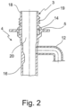
- the article cavity 3 can, for example, be used as a negative of the in figure 2 shown filling tube 4 may be formed.
- the tool 2 can include several moving components in the form of slides or the like and at least one secondary cavity. The secondary cavity can be shut off from article cavity 3 by means of slides. These details are not shown in the figure for reasons of simplification. Also not shown are an extruder and one or more runners that open into the article cavity 3 .
- the figure 1 shows one end of the article cavity 3 in an area that is used to form the in figure 2 illustrated filling head 5 of the filling tube 4 is formed.
- the injection molding device 1 also includes an injection device 6 which includes a nozzle body 7 .
- the injection device 6 is in figure 1 also not shown in full.
- the nozzle body 7 is movable relative to the tool 2 from a first shaping position to a second demolded position, wherein figure 1 shows the first formative position.
- this shaping position the nozzle body is immersed 7 into the article cavity 3 and seals the article cavity 3 at the end.
- the secondary cavity (not shown).
- the nozzle body 7 is designed as a mold core and as a projectile carrier for receiving a projectile 8 made of thermoplastic material.
- the nozzle body 7 includes a shaft 9 having a proximal end and a distal end, the proximal end sealing the article cavity 3 and the distal end receiving the projectile 8 .
- the shaft 9 has a first, larger diameter at its proximal end, and the shaft 9 has a second, smaller diameter at its distal end.
- the shank 9 is provided with longitudinally extending grooves 10 which form corresponding ribs in an inner boundary wall of the article to be manufactured.
- the shaft 9 forms an annular space with the article cavity 3, which can be filled with a thermoplastic molding compound via a sprue, not shown in the drawing.
- the sprue is not shown in the drawing; it is located downstream in relation to the direction of advance of the projectile 8 .
- the article cavity 3 includes a branch in which a side pipe 12 of the filling pipe 4 can be formed.
- a second projectile 13 is arranged laterally on the nozzle body 7 in order to form the secondary pipe 12 .
- the nozzle body 7 is interspersed with a fluid channel 15 through which a fluid under high pressure can be introduced into the article cavity 3 .
- the fluid channel 15 branches on the one hand to the distal end of the shaft 9, where it opens in the direction of the projectile 8, and on the other hand to the side Direction towards the second projectile 13.
- the fluid for example water under pressure
- the projectile 8 and the second projectile 13 being driven by the pressure of the fluid in the article cavity 3 push plastic molding material into the secondary cavity.
- the projectile 8 placed on the distal end of the shaft 9 has a maximum outer diameter that is larger than the second diameter of the shaft, so that the projectile 8 forms a temporary undercut of the nozzle body 7 that can be filled with the molding compound.
- an additional component in the form of a ring magnet 14 is also attached to the shaft 9 of the nozzle body 7, which is brought with the nozzle body 7 into the article cavity 3 before it is filled with the thermoplastic molding compound.
- the tool 2 is first closed, then the nozzle body 7 with the ring magnet 14 detachably attached to the shaft 9 is moved from a second demolding position to a first shaping position, in which the shaft 9 dips into the article cavity 3 and seal it.
- the article cavity 3 is then filled with the thermoplastic molding compound via one or more sprues (not shown).
- the filling can be full or partial.
- the thermoplastic molding compound also fills the article cavity in the area of the mold cavity 17 formed between the nozzle body 7 and the tool 2, the thermoplastic molding compound enclosing and embedding the ring magnet 14. Furthermore, the thermoplastic molding compound flows behind the projectile 8 since the diameter of the shank 9 (second diameter) immediately upstream of the projectile 8 is smaller than the maximum diameter of the projectile 8 .
- the secondary cavity (not shown) is released, for example, via a hydraulically actuated slide.
- a pressurized fluid for example water
- the fluid propels the projectiles 8, 13 through the article cavity 3, with the projectile 8 forming a main tube 16 and the second projectile 13 forming the secondary tube 12.
- the projectiles 8, 13 displace a molten core of the molding compound, the residual wall/boundary wall of the tube designed as a filling tube 4 remains.
- the nozzle body 7 is moved into a second demolded, i.e. retracted, position, with the ring magnet 14 remaining in the filled molding compound.
- the article is then demolded.
- the article in the form of the filling tube 4 is in figure 2 shown.
- the filler pipe comprises the main pipe, designated 16, which defines a fueling channel into a container, and the secondary pipe, designated 12, which forms a vent line.
- the filling tube 4 includes the filling head 5 with a mouth hole socket 18 which is provided with an external thread 19 .
- the mouth hole socket 18 encloses a filling channel 20 which extends from the mouth hole socket 18 through the filling head 5 into the main pipe 16 .
Landscapes
- Engineering & Computer Science (AREA)
- Mechanical Engineering (AREA)
- Manufacturing & Machinery (AREA)
- Injection Moulding Of Plastics Or The Like (AREA)
- Moulds For Moulding Plastics Or The Like (AREA)
Claims (12)
- Procédé de fabrication d'une pièce tubulaire en tant qu'article en matière synthétique thermoplastique à l'aide d'un dispositif de moulage par injection (1) comportant un outil (2) formant une cavité d'article (3), comportant des moyens permettant de remplir la cavité d'article (3) d'une matière de moulage thermoplastique et comportant un dispositif d'injection (6) permettant d'injecter un fluide dans la cavité d'article (3), dans lequel le dispositif d'injection (6) comprend un corps de buse (7), dans lequel selon le procédéle corps de buse (7) est utilisé en tant que noyau de moule pour le moulage d'une extrémité de l'article,le corps de buse (7) est utilisé en tant que support pour une pièce supplémentaire à introduire dans l'article,dans lequela) le corps de buse (7) est d'abord équipé de la pièce supplémentaire,b) le corps de buse (7) est inséré dans la cavité d'article (3) fermée ou l'outil (2) est fermé autour du corps de buse (7),c) la cavité d'article (3) est au moins partiellement remplie de la matière de moulage thermoplastique dans une autre étape,d) un fluide sous pression est ensuite introduit dans la cavité d'article (3) au moyen du dispositif d'injection (6), dans lequel une partie de la matière de moulage est déplacée dans une cavité secondaire ou un autre volume ete) l'article est démoulé.
- Procédé selon la revendication 1, caractérisé en ce que le corps de buse (7) est conçu sous la forme de support de projectile permettant de recevoir un projectile (8), qu'avant l'étape b), le corps de buse (7) est équipé d'au moins un projectile (8) et que le fluide introduit au moyen du dispositif d'injection (6) pousse le projectile (8) à travers la cavité d'article (3) tout en déplaçant un noyau fondu de la matière de moulage.
- Procédé selon l'une des revendications 1 ou 2, caractérisé en ce que la pièce supplémentaire est incorporée dans la matière de moulage thermoplastique.
- Procédé selon l'une quelconque des revendications 1 à 3, caractérisé en ce que le corps de buse (7) est retiré de la cavité d'article (3) après l'étape d) et avant l'étape e) de telle sorte que la pièce supplémentaire reste dans l'article.
- Procédé selon l'une quelconque des revendications 1 à 4, caractérisé en ce que la pièce supplémentaire est conçue sous la forme d'anneau (14) magnétique permanent, lequel est placé de manière amovible sur le corps de buse (7).
- Procédé selon l'une quelconque des revendications 1 à 5, caractérisé en ce que l'article est moulé en tant que tube ou tubulure d'un récipient de liquide, lequel définit un canal de remplissage (20).
- Procédé selon l'une quelconque des revendications 1 à 6, caractérisé en ce qu'une paroi de délimitation intérieure de l'article est profilée dans la direction longitudinale de telle sorte que celle-ci est, de préférence pourvue de nervures longitudinales.
- Procédé selon l'une quelconque des revendications 1 à 7, caractérisé en ce que la paroi de délimitation intérieure de l'article est conçue avec au moins un rétrécissement.
- Dispositif de moulage par injection permettant de mettre en oeuvre le procédé selon l'une quelconque des revendications 1 à 8, comportant un outil (2) formant une cavité d'article (3), comportant des moyens permettant de remplir la cavité d'article (3) d'une matière de moulage thermoplastique, comportant au moins un dispositif d'injection (6) permettant d'injecter un fluide dans la cavité d'article (3), dans lequel le dispositif d'injection (6) comprend un corps de buse (7), lequel comporte au moins un canal de fluide (15) pouvant être chargé avec un fluide sous pression, dans lequel le corps de buse (7) est conçu sous la forme de noyau de moule pour le moulage d'une extrémité de l'article, dans lequel le corps de buse (7) est approprié comme support pour une pièce supplémentaire à introduire dans l'article, dans lequel le corps de buse (7) comporte une tige (9) de mise en forme, laquelle, avec la cavité d'article (3), forme un espace creux de moulage (17) pouvant être rempli de la matière de moulage,
caractérisé en ce que
la tige (9) est profilée dans la direction longitudinale. - Dispositif de moulage par injection selon la revendication 9, caractérisé en ce que le corps de buse (7) est conçu sous la forme de support de projectile permettant de recevoir un projectile (8) en tant que corps de déplacement pour la matière de moulage.
- Dispositif de moulage par injection selon l'une des revendications 9 ou 10, caractérisé en ce que la tige (9) comporte une première section transversale supérieure et une seconde section transversale inférieure et que la tige (9) se rétrécit dans la direction d'une extrémité distale.
- Dispositif de moulage par injection selon la revendication 11, caractérisé en ce que l'extrémité distale est conçue sous la forme de logement de projectile et que le projectile (8) comporte une section transversale supérieure que la seconde section transversale.
Applications Claiming Priority (2)
| Application Number | Priority Date | Filing Date | Title |
|---|---|---|---|
| DE102016200484.0A DE102016200484C5 (de) | 2016-01-15 | 2016-01-15 | Verfahren und Vorrichtung zur Herstellung eines rohrförmigen Bauteils aus thermoplastischem Kunststoff durch Spritzgießen |
| PCT/EP2017/050434 WO2017121738A1 (fr) | 2016-01-15 | 2017-01-11 | Procédé et dispositif de fabrication d'un tuyau en matière thermoplastique par moulage par injection |
Publications (2)
| Publication Number | Publication Date |
|---|---|
| EP3402646A1 EP3402646A1 (fr) | 2018-11-21 |
| EP3402646B1 true EP3402646B1 (fr) | 2023-03-08 |
Family
ID=57838368
Family Applications (1)
| Application Number | Title | Priority Date | Filing Date |
|---|---|---|---|
| EP17700639.2A Active EP3402646B1 (fr) | 2016-01-15 | 2017-01-11 | Procédé et dispositif de fabrication d'un tuyau en matière thermoplastique par moulage par injection |
Country Status (5)
| Country | Link |
|---|---|
| US (1) | US10981308B2 (fr) |
| EP (1) | EP3402646B1 (fr) |
| CN (1) | CN109070417B (fr) |
| DE (1) | DE102016200484C5 (fr) |
| WO (1) | WO2017121738A1 (fr) |
Families Citing this family (1)
| Publication number | Priority date | Publication date | Assignee | Title |
|---|---|---|---|---|
| CN113276340B (zh) * | 2021-05-28 | 2023-05-05 | 上海延锋金桥汽车饰件系统有限公司 | 一种嵌件注塑方法及通过该嵌件注塑方法形成的注塑件 |
Family Cites Families (15)
| Publication number | Priority date | Publication date | Assignee | Title |
|---|---|---|---|---|
| JPS56121745A (en) | 1980-02-29 | 1981-09-24 | Toyoda Gosei Co Ltd | Foaming resin injection molding method |
| JP3204472B2 (ja) | 1992-11-16 | 2001-09-04 | キョーラク株式会社 | 樹脂製管状体の製造方法 |
| US20020001634A1 (en) | 2000-06-29 | 2002-01-03 | Toshio Komazawa | Molding tool for molding with cylindrical core |
| JP2002137253A (ja) | 2000-08-25 | 2002-05-14 | Mitsuboshi Belting Ltd | 射出成形用金型装置 |
| KR101321328B1 (ko) * | 2006-03-06 | 2013-10-23 | 니혼 클로져 가부시키가이샤 | 복합 스파우트 및 복합 스파우트를 형성하는 사출 성형 장치 |
| ATE423902T1 (de) | 2006-12-12 | 2009-03-15 | Magneti Marelli Powertrain Spa | Elektromagnetisches kraftstoffeinspritzventil für eine brennkraftmaschine mit direkteinspritzung |
| JP5078408B2 (ja) | 2007-03-30 | 2012-11-21 | 株式会社ホンダロック | 車両用アウトハンドル装置 |
| DE102008023473A1 (de) | 2008-05-14 | 2009-11-19 | Röchling Automotive AG & Co. KG | Kalibrator für Gießverfahren mit Projektilinjektion (PIT) |
| DE102009001276B3 (de) | 2009-03-02 | 2010-07-15 | Geiger Automotive Gmbh | Verfahren und Vorrichtung zur Herstellung eines Kunststoffteils |
| DE102010015453B3 (de) | 2010-04-17 | 2011-06-22 | Wittmann Battenfeld Gmbh | Vorrichtung und Verfahren zum Spritzgießen eines mindestens einen Hohlraum aufweisenden Formteils |
| DE102011009745B4 (de) | 2011-01-28 | 2012-09-13 | Kautex Textron Gmbh & Co. Kg | Einfüllstutzen für einen Nebenflüssigkeitsbehälter |
| DE102011015522A1 (de) | 2011-03-30 | 2012-10-04 | Andreas Stihl Ag & Co. Kg | Kunststoffkörper und Fertigungsanlage zur Herstellung eines Kunststoffkörpers |
| JP2012213919A (ja) | 2011-03-31 | 2012-11-08 | Fuji Heavy Ind Ltd | 管状中空成形品の製造方法及び成形型 |
| DE102011100132B4 (de) * | 2011-04-30 | 2020-07-23 | Vereinigung zur Förderung des Instituts für Kunststoffverarbeitung in Industrie und Handwerk an der Rhein.-Westf. Technischen Hochschule Aachen e.V. | Verfahren zur Herstellung polymererHohlkörper |
| DE102015102640A1 (de) | 2014-02-26 | 2015-08-27 | Geiger Automotive Gmbh | Herstellung eines mit einem Gewebeschlauch verstärkten Kunststoffschlauchs |
-
2016
- 2016-01-15 DE DE102016200484.0A patent/DE102016200484C5/de active Active
-
2017
- 2017-01-10 US US16/070,060 patent/US10981308B2/en active Active
- 2017-01-11 CN CN201780006402.4A patent/CN109070417B/zh active Active
- 2017-01-11 WO PCT/EP2017/050434 patent/WO2017121738A1/fr not_active Ceased
- 2017-01-11 EP EP17700639.2A patent/EP3402646B1/fr active Active
Also Published As
| Publication number | Publication date |
|---|---|
| CN109070417B (zh) | 2020-12-04 |
| WO2017121738A1 (fr) | 2017-07-20 |
| DE102016200484A1 (de) | 2017-07-20 |
| US10981308B2 (en) | 2021-04-20 |
| CN109070417A (zh) | 2018-12-21 |
| US20180354172A1 (en) | 2018-12-13 |
| EP3402646A1 (fr) | 2018-11-21 |
| DE102016200484B4 (de) | 2017-08-17 |
| DE102016200484C5 (de) | 2022-12-01 |
Similar Documents
| Publication | Publication Date | Title |
|---|---|---|
| DE2140311C3 (de) | Schlauchendstück und Vorrichtung zur Herstellung desselben | |
| EP3389978B1 (fr) | Procédé pour la fabrication d'un tube ainsi que dispositif de moulage par injection | |
| EP2377665B1 (fr) | Dispositif et procédé de moulage par injection d'un élément de formage comprenant au moins un espace creux | |
| EP3308933B1 (fr) | Dispositif et procédé de fabrication d'une tête de tube | |
| EP3377294B1 (fr) | Dispositif de moulage par injection pour la fabrication des tuyaux avec un filetage intérieur et procédé de production desdits tuyaux | |
| DE102009031441A1 (de) | Verfahren zur Herstellung eines Artikels aus thermoplastischem Kunststoff | |
| EP3389977B1 (fr) | Dispositif de moulage par injection pour la fabrication de pièces moulées à plusieurs composants ainsi que procédé pour la fabrication de pièces moulées à plusieurs composants | |
| DE102008023473A1 (de) | Kalibrator für Gießverfahren mit Projektilinjektion (PIT) | |
| EP3402646B1 (fr) | Procédé et dispositif de fabrication d'un tuyau en matière thermoplastique par moulage par injection | |
| WO2018095747A1 (fr) | Procédé de fabrication d'un récipient | |
| EP3259110B1 (fr) | Procédé de formage par extrusion-soufflage d'un récipient en matière synthétique thermoplastique et récipient formé par extrusion-soufflage | |
| WO2025067610A1 (fr) | Pièce moulée en matière plastique moulée par injection, procédé de fabrication de la pièce moulée, insert pour la mise en œuvre du procédé et moule d'injection pour la mise en œuvre dudit procédé | |
| EP1005408A1 (fr) | Procede et dispositif de moulage par injection de pieces en materiau plastifiable | |
| DE102017204797A1 (de) | Verfahren und Vorrichtung zur Herstellung eines Bauteils aus thermoplastischem Kunststoff sowie Bauteil hergestellt nach dem Verfahren | |
| EP2706271A1 (fr) | Soufflet à plis et procédé de fabrication dýun soufflet à plis | |
| DE102012107045A1 (de) | Verfahren zur Herstellung eines Auftraggeräts und Auftraggerät | |
| AT522894B1 (de) | Verfahren zur Herstellung eines Betriebsmitteltanks | |
| WO2025202408A1 (fr) | Outil de moulage par injection et procédé de fabrication d'une manivelle de pédalier pour une bicyclette | |
| DE4235776A1 (de) | Formwerkzeug zum Herstellen von Kunststoffteilen sowie Verfahren zum Herstellen eines solchen Formwerkzeugs | |
| DE102013220990A1 (de) | Blasschlauch für Innendruck-Spritzgießen | |
| EP3405324A1 (fr) | Procédé de moulage par injection d'un composant en plastique et composant en plastique | |
| DE102013221008A1 (de) | Verfahren zum Herstellen eines Kunststoff-Formteils und Vorrichtung zum Herstellen eines Kunststoff-Formteils | |
| WO2017125303A1 (fr) | Procédé de moulage par injection d'un composant en plastique et composant en plastique |
Legal Events
| Date | Code | Title | Description |
|---|---|---|---|
| STAA | Information on the status of an ep patent application or granted ep patent |
Free format text: STATUS: UNKNOWN |
|
| STAA | Information on the status of an ep patent application or granted ep patent |
Free format text: STATUS: THE INTERNATIONAL PUBLICATION HAS BEEN MADE |
|
| PUAI | Public reference made under article 153(3) epc to a published international application that has entered the european phase |
Free format text: ORIGINAL CODE: 0009012 |
|
| STAA | Information on the status of an ep patent application or granted ep patent |
Free format text: STATUS: REQUEST FOR EXAMINATION WAS MADE |
|
| 17P | Request for examination filed |
Effective date: 20180717 |
|
| AK | Designated contracting states |
Kind code of ref document: A1 Designated state(s): AL AT BE BG CH CY CZ DE DK EE ES FI FR GB GR HR HU IE IS IT LI LT LU LV MC MK MT NL NO PL PT RO RS SE SI SK SM TR |
|
| AX | Request for extension of the european patent |
Extension state: BA ME |
|
| DAV | Request for validation of the european patent (deleted) | ||
| DAX | Request for extension of the european patent (deleted) | ||
| STAA | Information on the status of an ep patent application or granted ep patent |
Free format text: STATUS: EXAMINATION IS IN PROGRESS |
|
| 17Q | First examination report despatched |
Effective date: 20191004 |
|
| GRAP | Despatch of communication of intention to grant a patent |
Free format text: ORIGINAL CODE: EPIDOSNIGR1 |
|
| STAA | Information on the status of an ep patent application or granted ep patent |
Free format text: STATUS: GRANT OF PATENT IS INTENDED |
|
| GRAS | Grant fee paid |
Free format text: ORIGINAL CODE: EPIDOSNIGR3 |
|
| INTG | Intention to grant announced |
Effective date: 20230103 |
|
| GRAA | (expected) grant |
Free format text: ORIGINAL CODE: 0009210 |
|
| STAA | Information on the status of an ep patent application or granted ep patent |
Free format text: STATUS: THE PATENT HAS BEEN GRANTED |
|
| AK | Designated contracting states |
Kind code of ref document: B1 Designated state(s): AL AT BE BG CH CY CZ DE DK EE ES FI FR GB GR HR HU IE IS IT LI LT LU LV MC MK MT NL NO PL PT RO RS SE SI SK SM TR |
|
| REG | Reference to a national code |
Ref country code: GB Ref legal event code: FG4D Free format text: NOT ENGLISH |
|
| REG | Reference to a national code |
Ref country code: CH Ref legal event code: EP Ref country code: AT Ref legal event code: REF Ref document number: 1552289 Country of ref document: AT Kind code of ref document: T Effective date: 20230315 |
|
| REG | Reference to a national code |
Ref country code: DE Ref legal event code: R096 Ref document number: 502017014478 Country of ref document: DE |
|
| REG | Reference to a national code |
Ref country code: IE Ref legal event code: FG4D Free format text: LANGUAGE OF EP DOCUMENT: GERMAN |
|
| REG | Reference to a national code |
Ref country code: LT Ref legal event code: MG9D |
|
| P01 | Opt-out of the competence of the unified patent court (upc) registered |
Effective date: 20230526 |
|
| REG | Reference to a national code |
Ref country code: NL Ref legal event code: MP Effective date: 20230308 |
|
| PG25 | Lapsed in a contracting state [announced via postgrant information from national office to epo] |
Ref country code: RS Free format text: LAPSE BECAUSE OF FAILURE TO SUBMIT A TRANSLATION OF THE DESCRIPTION OR TO PAY THE FEE WITHIN THE PRESCRIBED TIME-LIMIT Effective date: 20230308 Ref country code: NO Free format text: LAPSE BECAUSE OF FAILURE TO SUBMIT A TRANSLATION OF THE DESCRIPTION OR TO PAY THE FEE WITHIN THE PRESCRIBED TIME-LIMIT Effective date: 20230608 Ref country code: LV Free format text: LAPSE BECAUSE OF FAILURE TO SUBMIT A TRANSLATION OF THE DESCRIPTION OR TO PAY THE FEE WITHIN THE PRESCRIBED TIME-LIMIT Effective date: 20230308 Ref country code: LT Free format text: LAPSE BECAUSE OF FAILURE TO SUBMIT A TRANSLATION OF THE DESCRIPTION OR TO PAY THE FEE WITHIN THE PRESCRIBED TIME-LIMIT Effective date: 20230308 Ref country code: HR Free format text: LAPSE BECAUSE OF FAILURE TO SUBMIT A TRANSLATION OF THE DESCRIPTION OR TO PAY THE FEE WITHIN THE PRESCRIBED TIME-LIMIT Effective date: 20230308 Ref country code: ES Free format text: LAPSE BECAUSE OF FAILURE TO SUBMIT A TRANSLATION OF THE DESCRIPTION OR TO PAY THE FEE WITHIN THE PRESCRIBED TIME-LIMIT Effective date: 20230308 |
|
| PG25 | Lapsed in a contracting state [announced via postgrant information from national office to epo] |
Ref country code: SE Free format text: LAPSE BECAUSE OF FAILURE TO SUBMIT A TRANSLATION OF THE DESCRIPTION OR TO PAY THE FEE WITHIN THE PRESCRIBED TIME-LIMIT Effective date: 20230308 Ref country code: NL Free format text: LAPSE BECAUSE OF FAILURE TO SUBMIT A TRANSLATION OF THE DESCRIPTION OR TO PAY THE FEE WITHIN THE PRESCRIBED TIME-LIMIT Effective date: 20230308 Ref country code: GR Free format text: LAPSE BECAUSE OF FAILURE TO SUBMIT A TRANSLATION OF THE DESCRIPTION OR TO PAY THE FEE WITHIN THE PRESCRIBED TIME-LIMIT Effective date: 20230609 Ref country code: FI Free format text: LAPSE BECAUSE OF FAILURE TO SUBMIT A TRANSLATION OF THE DESCRIPTION OR TO PAY THE FEE WITHIN THE PRESCRIBED TIME-LIMIT Effective date: 20230308 |
|
| PG25 | Lapsed in a contracting state [announced via postgrant information from national office to epo] |
Ref country code: SM Free format text: LAPSE BECAUSE OF FAILURE TO SUBMIT A TRANSLATION OF THE DESCRIPTION OR TO PAY THE FEE WITHIN THE PRESCRIBED TIME-LIMIT Effective date: 20230308 Ref country code: RO Free format text: LAPSE BECAUSE OF FAILURE TO SUBMIT A TRANSLATION OF THE DESCRIPTION OR TO PAY THE FEE WITHIN THE PRESCRIBED TIME-LIMIT Effective date: 20230308 Ref country code: PT Free format text: LAPSE BECAUSE OF FAILURE TO SUBMIT A TRANSLATION OF THE DESCRIPTION OR TO PAY THE FEE WITHIN THE PRESCRIBED TIME-LIMIT Effective date: 20230710 Ref country code: EE Free format text: LAPSE BECAUSE OF FAILURE TO SUBMIT A TRANSLATION OF THE DESCRIPTION OR TO PAY THE FEE WITHIN THE PRESCRIBED TIME-LIMIT Effective date: 20230308 Ref country code: CZ Free format text: LAPSE BECAUSE OF FAILURE TO SUBMIT A TRANSLATION OF THE DESCRIPTION OR TO PAY THE FEE WITHIN THE PRESCRIBED TIME-LIMIT Effective date: 20230308 |
|
| PG25 | Lapsed in a contracting state [announced via postgrant information from national office to epo] |
Ref country code: SK Free format text: LAPSE BECAUSE OF FAILURE TO SUBMIT A TRANSLATION OF THE DESCRIPTION OR TO PAY THE FEE WITHIN THE PRESCRIBED TIME-LIMIT Effective date: 20230308 Ref country code: PL Free format text: LAPSE BECAUSE OF FAILURE TO SUBMIT A TRANSLATION OF THE DESCRIPTION OR TO PAY THE FEE WITHIN THE PRESCRIBED TIME-LIMIT Effective date: 20230308 Ref country code: IS Free format text: LAPSE BECAUSE OF FAILURE TO SUBMIT A TRANSLATION OF THE DESCRIPTION OR TO PAY THE FEE WITHIN THE PRESCRIBED TIME-LIMIT Effective date: 20230708 |
|
| REG | Reference to a national code |
Ref country code: DE Ref legal event code: R097 Ref document number: 502017014478 Country of ref document: DE |
|
| PLBE | No opposition filed within time limit |
Free format text: ORIGINAL CODE: 0009261 |
|
| STAA | Information on the status of an ep patent application or granted ep patent |
Free format text: STATUS: NO OPPOSITION FILED WITHIN TIME LIMIT |
|
| PG25 | Lapsed in a contracting state [announced via postgrant information from national office to epo] |
Ref country code: SI Free format text: LAPSE BECAUSE OF FAILURE TO SUBMIT A TRANSLATION OF THE DESCRIPTION OR TO PAY THE FEE WITHIN THE PRESCRIBED TIME-LIMIT Effective date: 20230308 Ref country code: DK Free format text: LAPSE BECAUSE OF FAILURE TO SUBMIT A TRANSLATION OF THE DESCRIPTION OR TO PAY THE FEE WITHIN THE PRESCRIBED TIME-LIMIT Effective date: 20230308 |
|
| 26N | No opposition filed |
Effective date: 20231211 |
|
| PG25 | Lapsed in a contracting state [announced via postgrant information from national office to epo] |
Ref country code: IT Free format text: LAPSE BECAUSE OF FAILURE TO SUBMIT A TRANSLATION OF THE DESCRIPTION OR TO PAY THE FEE WITHIN THE PRESCRIBED TIME-LIMIT Effective date: 20230308 |
|
| PG25 | Lapsed in a contracting state [announced via postgrant information from national office to epo] |
Ref country code: MC Free format text: LAPSE BECAUSE OF FAILURE TO SUBMIT A TRANSLATION OF THE DESCRIPTION OR TO PAY THE FEE WITHIN THE PRESCRIBED TIME-LIMIT Effective date: 20230308 |
|
| PG25 | Lapsed in a contracting state [announced via postgrant information from national office to epo] |
Ref country code: MC Free format text: LAPSE BECAUSE OF FAILURE TO SUBMIT A TRANSLATION OF THE DESCRIPTION OR TO PAY THE FEE WITHIN THE PRESCRIBED TIME-LIMIT Effective date: 20230308 |
|
| REG | Reference to a national code |
Ref country code: CH Ref legal event code: PL |
|
| PG25 | Lapsed in a contracting state [announced via postgrant information from national office to epo] |
Ref country code: LU Free format text: LAPSE BECAUSE OF NON-PAYMENT OF DUE FEES Effective date: 20240111 |
|
| PG25 | Lapsed in a contracting state [announced via postgrant information from national office to epo] |
Ref country code: LU Free format text: LAPSE BECAUSE OF NON-PAYMENT OF DUE FEES Effective date: 20240111 |
|
| PG25 | Lapsed in a contracting state [announced via postgrant information from national office to epo] |
Ref country code: BE Free format text: LAPSE BECAUSE OF NON-PAYMENT OF DUE FEES Effective date: 20240131 |
|
| PG25 | Lapsed in a contracting state [announced via postgrant information from national office to epo] |
Ref country code: CH Free format text: LAPSE BECAUSE OF NON-PAYMENT OF DUE FEES Effective date: 20240131 |
|
| PG25 | Lapsed in a contracting state [announced via postgrant information from national office to epo] |
Ref country code: CH Free format text: LAPSE BECAUSE OF NON-PAYMENT OF DUE FEES Effective date: 20240131 Ref country code: BE Free format text: LAPSE BECAUSE OF NON-PAYMENT OF DUE FEES Effective date: 20240131 |
|
| REG | Reference to a national code |
Ref country code: BE Ref legal event code: MM Effective date: 20240131 |
|
| PG25 | Lapsed in a contracting state [announced via postgrant information from national office to epo] |
Ref country code: BG Free format text: LAPSE BECAUSE OF FAILURE TO SUBMIT A TRANSLATION OF THE DESCRIPTION OR TO PAY THE FEE WITHIN THE PRESCRIBED TIME-LIMIT Effective date: 20230308 |
|
| PG25 | Lapsed in a contracting state [announced via postgrant information from national office to epo] |
Ref country code: BG Free format text: LAPSE BECAUSE OF FAILURE TO SUBMIT A TRANSLATION OF THE DESCRIPTION OR TO PAY THE FEE WITHIN THE PRESCRIBED TIME-LIMIT Effective date: 20230308 |
|
| PG25 | Lapsed in a contracting state [announced via postgrant information from national office to epo] |
Ref country code: IE Free format text: LAPSE BECAUSE OF NON-PAYMENT OF DUE FEES Effective date: 20240111 |
|
| PG25 | Lapsed in a contracting state [announced via postgrant information from national office to epo] |
Ref country code: IE Free format text: LAPSE BECAUSE OF NON-PAYMENT OF DUE FEES Effective date: 20240111 |
|
| REG | Reference to a national code |
Ref country code: AT Ref legal event code: MM01 Ref document number: 1552289 Country of ref document: AT Kind code of ref document: T Effective date: 20240111 |
|
| PG25 | Lapsed in a contracting state [announced via postgrant information from national office to epo] |
Ref country code: AT Free format text: LAPSE BECAUSE OF NON-PAYMENT OF DUE FEES Effective date: 20240111 |
|
| PG25 | Lapsed in a contracting state [announced via postgrant information from national office to epo] |
Ref country code: CY Free format text: LAPSE BECAUSE OF FAILURE TO SUBMIT A TRANSLATION OF THE DESCRIPTION OR TO PAY THE FEE WITHIN THE PRESCRIBED TIME-LIMIT; INVALID AB INITIO Effective date: 20170111 |
|
| PG25 | Lapsed in a contracting state [announced via postgrant information from national office to epo] |
Ref country code: HU Free format text: LAPSE BECAUSE OF FAILURE TO SUBMIT A TRANSLATION OF THE DESCRIPTION OR TO PAY THE FEE WITHIN THE PRESCRIBED TIME-LIMIT; INVALID AB INITIO Effective date: 20170111 |
|
| PG25 | Lapsed in a contracting state [announced via postgrant information from national office to epo] |
Ref country code: TR Free format text: LAPSE BECAUSE OF FAILURE TO SUBMIT A TRANSLATION OF THE DESCRIPTION OR TO PAY THE FEE WITHIN THE PRESCRIBED TIME-LIMIT Effective date: 20230308 |
|
| PGFP | Annual fee paid to national office [announced via postgrant information from national office to epo] |
Ref country code: GB Payment date: 20260123 Year of fee payment: 10 |
|
| PGFP | Annual fee paid to national office [announced via postgrant information from national office to epo] |
Ref country code: DE Payment date: 20260108 Year of fee payment: 10 |
|
| PGFP | Annual fee paid to national office [announced via postgrant information from national office to epo] |
Ref country code: FR Payment date: 20260123 Year of fee payment: 10 |