EP3402646B1 - Method and device for producing a tube from thermoplastic synthetic material via injection moulding - Google Patents
Method and device for producing a tube from thermoplastic synthetic material via injection moulding Download PDFInfo
- Publication number
- EP3402646B1 EP3402646B1 EP17700639.2A EP17700639A EP3402646B1 EP 3402646 B1 EP3402646 B1 EP 3402646B1 EP 17700639 A EP17700639 A EP 17700639A EP 3402646 B1 EP3402646 B1 EP 3402646B1
- Authority
- EP
- European Patent Office
- Prior art keywords
- article
- nozzle body
- cavity
- projectile
- injection
- Prior art date
- Legal status (The legal status is an assumption and is not a legal conclusion. Google has not performed a legal analysis and makes no representation as to the accuracy of the status listed.)
- Active
Links
Images

Classifications
-
- B—PERFORMING OPERATIONS; TRANSPORTING
- B29—WORKING OF PLASTICS; WORKING OF SUBSTANCES IN A PLASTIC STATE IN GENERAL
- B29C—SHAPING OR JOINING OF PLASTICS; SHAPING OF MATERIAL IN A PLASTIC STATE, NOT OTHERWISE PROVIDED FOR; AFTER-TREATMENT OF THE SHAPED PRODUCTS, e.g. REPAIRING
- B29C45/00—Injection moulding, i.e. forcing the required volume of moulding material through a nozzle into a closed mould; Apparatus therefor
- B29C45/14—Injection moulding, i.e. forcing the required volume of moulding material through a nozzle into a closed mould; Apparatus therefor incorporating preformed parts or layers, e.g. injection moulding around inserts or for coating articles
- B29C45/14065—Positioning or centering articles in the mould
-
- B—PERFORMING OPERATIONS; TRANSPORTING
- B29—WORKING OF PLASTICS; WORKING OF SUBSTANCES IN A PLASTIC STATE IN GENERAL
- B29B—PREPARATION OR PRETREATMENT OF THE MATERIAL TO BE SHAPED; MAKING GRANULES OR PREFORMS; RECOVERY OF PLASTICS OR OTHER CONSTITUENTS OF WASTE MATERIAL CONTAINING PLASTICS
- B29B11/00—Making preforms
- B29B11/06—Making preforms by moulding the material
- B29B11/08—Injection moulding
-
- B—PERFORMING OPERATIONS; TRANSPORTING
- B29—WORKING OF PLASTICS; WORKING OF SUBSTANCES IN A PLASTIC STATE IN GENERAL
- B29C—SHAPING OR JOINING OF PLASTICS; SHAPING OF MATERIAL IN A PLASTIC STATE, NOT OTHERWISE PROVIDED FOR; AFTER-TREATMENT OF THE SHAPED PRODUCTS, e.g. REPAIRING
- B29C45/00—Injection moulding, i.e. forcing the required volume of moulding material through a nozzle into a closed mould; Apparatus therefor
- B29C45/14—Injection moulding, i.e. forcing the required volume of moulding material through a nozzle into a closed mould; Apparatus therefor incorporating preformed parts or layers, e.g. injection moulding around inserts or for coating articles
- B29C45/14819—Injection moulding, i.e. forcing the required volume of moulding material through a nozzle into a closed mould; Apparatus therefor incorporating preformed parts or layers, e.g. injection moulding around inserts or for coating articles the inserts being completely encapsulated
-
- B—PERFORMING OPERATIONS; TRANSPORTING
- B29—WORKING OF PLASTICS; WORKING OF SUBSTANCES IN A PLASTIC STATE IN GENERAL
- B29C—SHAPING OR JOINING OF PLASTICS; SHAPING OF MATERIAL IN A PLASTIC STATE, NOT OTHERWISE PROVIDED FOR; AFTER-TREATMENT OF THE SHAPED PRODUCTS, e.g. REPAIRING
- B29C45/00—Injection moulding, i.e. forcing the required volume of moulding material through a nozzle into a closed mould; Apparatus therefor
- B29C45/17—Component parts, details or accessories; Auxiliary operations
- B29C45/1703—Introducing an auxiliary fluid into the mould
- B29C45/1704—Introducing an auxiliary fluid into the mould the fluid being introduced into the interior of the injected material which is still in a molten state, e.g. for producing hollow articles
-
- B—PERFORMING OPERATIONS; TRANSPORTING
- B29—WORKING OF PLASTICS; WORKING OF SUBSTANCES IN A PLASTIC STATE IN GENERAL
- B29C—SHAPING OR JOINING OF PLASTICS; SHAPING OF MATERIAL IN A PLASTIC STATE, NOT OTHERWISE PROVIDED FOR; AFTER-TREATMENT OF THE SHAPED PRODUCTS, e.g. REPAIRING
- B29C45/00—Injection moulding, i.e. forcing the required volume of moulding material through a nozzle into a closed mould; Apparatus therefor
- B29C45/17—Component parts, details or accessories; Auxiliary operations
- B29C45/1703—Introducing an auxiliary fluid into the mould
- B29C45/1734—Nozzles therefor
-
- B—PERFORMING OPERATIONS; TRANSPORTING
- B29—WORKING OF PLASTICS; WORKING OF SUBSTANCES IN A PLASTIC STATE IN GENERAL
- B29C—SHAPING OR JOINING OF PLASTICS; SHAPING OF MATERIAL IN A PLASTIC STATE, NOT OTHERWISE PROVIDED FOR; AFTER-TREATMENT OF THE SHAPED PRODUCTS, e.g. REPAIRING
- B29C45/00—Injection moulding, i.e. forcing the required volume of moulding material through a nozzle into a closed mould; Apparatus therefor
- B29C45/17—Component parts, details or accessories; Auxiliary operations
- B29C45/20—Injection nozzles
-
- B—PERFORMING OPERATIONS; TRANSPORTING
- B29—WORKING OF PLASTICS; WORKING OF SUBSTANCES IN A PLASTIC STATE IN GENERAL
- B29C—SHAPING OR JOINING OF PLASTICS; SHAPING OF MATERIAL IN A PLASTIC STATE, NOT OTHERWISE PROVIDED FOR; AFTER-TREATMENT OF THE SHAPED PRODUCTS, e.g. REPAIRING
- B29C45/00—Injection moulding, i.e. forcing the required volume of moulding material through a nozzle into a closed mould; Apparatus therefor
- B29C45/17—Component parts, details or accessories; Auxiliary operations
- B29C45/26—Moulds
- B29C45/261—Moulds having tubular mould cavities
-
- B—PERFORMING OPERATIONS; TRANSPORTING
- B29—WORKING OF PLASTICS; WORKING OF SUBSTANCES IN A PLASTIC STATE IN GENERAL
- B29C—SHAPING OR JOINING OF PLASTICS; SHAPING OF MATERIAL IN A PLASTIC STATE, NOT OTHERWISE PROVIDED FOR; AFTER-TREATMENT OF THE SHAPED PRODUCTS, e.g. REPAIRING
- B29C45/00—Injection moulding, i.e. forcing the required volume of moulding material through a nozzle into a closed mould; Apparatus therefor
- B29C2045/0087—Injection moulding, i.e. forcing the required volume of moulding material through a nozzle into a closed mould; Apparatus therefor making hollow articles using a floating core movable in the mould cavity by fluid pressure and expelling molten excess material
-
- B—PERFORMING OPERATIONS; TRANSPORTING
- B29—WORKING OF PLASTICS; WORKING OF SUBSTANCES IN A PLASTIC STATE IN GENERAL
- B29C—SHAPING OR JOINING OF PLASTICS; SHAPING OF MATERIAL IN A PLASTIC STATE, NOT OTHERWISE PROVIDED FOR; AFTER-TREATMENT OF THE SHAPED PRODUCTS, e.g. REPAIRING
- B29C2949/00—Indexing scheme relating to blow-moulding
- B29C2949/07—Preforms or parisons characterised by their configuration
- B29C2949/0715—Preforms or parisons characterised by their configuration the preform having one end closed
-
- B—PERFORMING OPERATIONS; TRANSPORTING
- B29—WORKING OF PLASTICS; WORKING OF SUBSTANCES IN A PLASTIC STATE IN GENERAL
- B29C—SHAPING OR JOINING OF PLASTICS; SHAPING OF MATERIAL IN A PLASTIC STATE, NOT OTHERWISE PROVIDED FOR; AFTER-TREATMENT OF THE SHAPED PRODUCTS, e.g. REPAIRING
- B29C2949/00—Indexing scheme relating to blow-moulding
- B29C2949/07—Preforms or parisons characterised by their configuration
- B29C2949/076—Preforms or parisons characterised by their configuration characterised by the shape
- B29C2949/0768—Preforms or parisons characterised by their configuration characterised by the shape characterised by the shape of specific parts of preform
- B29C2949/077—Preforms or parisons characterised by their configuration characterised by the shape characterised by the shape of specific parts of preform characterised by the neck
- B29C2949/0772—Closure retaining means
- B29C2949/0773—Threads
-
- B—PERFORMING OPERATIONS; TRANSPORTING
- B29—WORKING OF PLASTICS; WORKING OF SUBSTANCES IN A PLASTIC STATE IN GENERAL
- B29C—SHAPING OR JOINING OF PLASTICS; SHAPING OF MATERIAL IN A PLASTIC STATE, NOT OTHERWISE PROVIDED FOR; AFTER-TREATMENT OF THE SHAPED PRODUCTS, e.g. REPAIRING
- B29C2949/00—Indexing scheme relating to blow-moulding
- B29C2949/07—Preforms or parisons characterised by their configuration
- B29C2949/079—Auxiliary parts or inserts
-
- B—PERFORMING OPERATIONS; TRANSPORTING
- B29—WORKING OF PLASTICS; WORKING OF SUBSTANCES IN A PLASTIC STATE IN GENERAL
- B29C—SHAPING OR JOINING OF PLASTICS; SHAPING OF MATERIAL IN A PLASTIC STATE, NOT OTHERWISE PROVIDED FOR; AFTER-TREATMENT OF THE SHAPED PRODUCTS, e.g. REPAIRING
- B29C2949/00—Indexing scheme relating to blow-moulding
- B29C2949/20—Preforms or parisons whereby a specific part is made of only one component, e.g. only one layer
-
- B—PERFORMING OPERATIONS; TRANSPORTING
- B29—WORKING OF PLASTICS; WORKING OF SUBSTANCES IN A PLASTIC STATE IN GENERAL
- B29C—SHAPING OR JOINING OF PLASTICS; SHAPING OF MATERIAL IN A PLASTIC STATE, NOT OTHERWISE PROVIDED FOR; AFTER-TREATMENT OF THE SHAPED PRODUCTS, e.g. REPAIRING
- B29C45/00—Injection moulding, i.e. forcing the required volume of moulding material through a nozzle into a closed mould; Apparatus therefor
- B29C45/14—Injection moulding, i.e. forcing the required volume of moulding material through a nozzle into a closed mould; Apparatus therefor incorporating preformed parts or layers, e.g. injection moulding around inserts or for coating articles
- B29C45/1459—Coating annular articles
-
- B—PERFORMING OPERATIONS; TRANSPORTING
- B29—WORKING OF PLASTICS; WORKING OF SUBSTANCES IN A PLASTIC STATE IN GENERAL
- B29C—SHAPING OR JOINING OF PLASTICS; SHAPING OF MATERIAL IN A PLASTIC STATE, NOT OTHERWISE PROVIDED FOR; AFTER-TREATMENT OF THE SHAPED PRODUCTS, e.g. REPAIRING
- B29C49/00—Blow-moulding, i.e. blowing a preform or parison to a desired shape within a mould; Apparatus therefor
- B29C49/02—Combined blow-moulding and manufacture of the preform or the parison
- B29C49/06—Injection blow-moulding
-
- B—PERFORMING OPERATIONS; TRANSPORTING
- B29—WORKING OF PLASTICS; WORKING OF SUBSTANCES IN A PLASTIC STATE IN GENERAL
- B29K—INDEXING SCHEME ASSOCIATED WITH SUBCLASSES B29B, B29C OR B29D, RELATING TO MOULDING MATERIALS OR TO MATERIALS FOR MOULDS, REINFORCEMENTS, FILLERS OR PREFORMED PARTS, e.g. INSERTS
- B29K2101/00—Use of unspecified macromolecular compounds as moulding material
- B29K2101/12—Thermoplastic materials
-
- B—PERFORMING OPERATIONS; TRANSPORTING
- B29—WORKING OF PLASTICS; WORKING OF SUBSTANCES IN A PLASTIC STATE IN GENERAL
- B29K—INDEXING SCHEME ASSOCIATED WITH SUBCLASSES B29B, B29C OR B29D, RELATING TO MOULDING MATERIALS OR TO MATERIALS FOR MOULDS, REINFORCEMENTS, FILLERS OR PREFORMED PARTS, e.g. INSERTS
- B29K2905/00—Use of metals, their alloys or their compounds, as mould material
-
- B—PERFORMING OPERATIONS; TRANSPORTING
- B29—WORKING OF PLASTICS; WORKING OF SUBSTANCES IN A PLASTIC STATE IN GENERAL
- B29K—INDEXING SCHEME ASSOCIATED WITH SUBCLASSES B29B, B29C OR B29D, RELATING TO MOULDING MATERIALS OR TO MATERIALS FOR MOULDS, REINFORCEMENTS, FILLERS OR PREFORMED PARTS, e.g. INSERTS
- B29K2995/00—Properties of moulding materials, reinforcements, fillers, preformed parts or moulds
- B29K2995/0003—Properties of moulding materials, reinforcements, fillers, preformed parts or moulds having particular electrical or magnetic properties, e.g. piezoelectric
- B29K2995/0008—Magnetic or paramagnetic
-
- B—PERFORMING OPERATIONS; TRANSPORTING
- B29—WORKING OF PLASTICS; WORKING OF SUBSTANCES IN A PLASTIC STATE IN GENERAL
- B29L—INDEXING SCHEME ASSOCIATED WITH SUBCLASS B29C, RELATING TO PARTICULAR ARTICLES
- B29L2031/00—Other particular articles
- B29L2031/712—Containers; Packaging elements or accessories, Packages
Definitions
- the invention relates to a method for producing a tubular component as an article made of thermoplastic material using an injection molding device.
- the invention also relates to an injection molding device for producing such a tubular component.
- the invention relates to a method for producing an article as a pipe or pipe socket of a liquid container.
- filler pipes for fuel tanks or for additive tanks for motor vehicles are nowadays blow-molded or vulcanized in sections and then assembled from individual sections.
- the filler pipe head is assembled as an injection weld assembly at the top end of a pipe, for example extrusion blow molded. Ventilation lines connected to the side are fastened to welded nipples.
- the production of a filler pipe in the manner described above is relatively expensive. Every assembly and every weld generates costs. After the filler pipe has been assembled, it must be checked for leaks, which incurs additional costs.
- a filler neck for a urea tank of a motor vehicle having a neck housing that defines a mouth hole neck for a nozzle and a filling channel into the tank, with a receiving structure for a nozzle being provided inside the neck housing.
- the nozzle housing encloses furthermore, a ring magnet which is encapsulated in a liquid-tight manner in a ring-shaped plastic housing within the socket housing.
- a pipe socket of a liquid container is known, which is designed as an injection-molded composite component.
- a method of making a braided hose reinforced plastic hose using a projectile injection method is known from US Pat DE 10 2015 102 640 A1 known.
- a method for producing a tubular plastic part is also known from DE 2009 001 276 B3 known.
- JP 2002 137253 A discloses an injection molding device for producing hollow molded parts by means of gas injection.
- the invention is based on the object of using a method for producing a tubular component as an article made of thermoplastic material provide an injection molding device, which is simplified compared to the previously known method.
- a complex tubular component for example as a pipe socket or socket housing with a filling channel, should be possible in as few work steps as possible.
- the invention is also based on the object of providing a corresponding injection molding device.
- the object on which the invention is based is further achieved by an injection molding device having the features of claim 9 .
- Process steps a) to e) are preferably carried out in the order in which they are listed, it not being ruled out that the process also includes intermediate steps in each case.
- thermoplastic molding compound within the meaning of the present invention is a plasticized thermoplastic material that is fed, for example, to the injection molding device or the tool by means of an extruder via a sprue.
- the secondary cavity can be closed, for example, by means of one or more slides until the article cavity is partially or completely filled; the slide is then preferably opened after method step c), so that the pressurized fluid forces a molten core of the molding compound into the secondary cavity, wherein the non-displaced part of the molding compound forms a standing article wall.
- the molding compound can be displaced into another volume.
- provision can be made, for example, for the molding compound to be conveyed back into an extruder that was used to prepare the molding compound.
- thermoplastic polymer can be provided as the thermoplastic molding compound within the meaning of the invention.
- a thermoplastic can be provided as the thermoplastic molding compound, which is selected from a group comprising high-density polyethylene, polyamide, polyamide 6, Polyamide 12, polyurethane, polycarbonate, acrylonitrile-butadiene-styrene copolymer, polyketones, polystyrene, olefin-based thermoplastic elastomers, crosslinked olefin-based thermoplastic elastomers, urethane-based thermoplastic elastomers, thermoplastic polyester elastomers and thermoplastic copolymers.
- the nozzle body closes and seals the article cavity at one end of the article cavity, which forms a negative of the tubular component, with the nozzle body dipping into the article cavity and there forming a hollow space that can be filled with the thermoplastic molding compound with the article cavity, preferably forms an annular space.
- the additional component to be introduced into the article.
- the two-part tool for example, is opened, the nozzle body is equipped with the additional component when the tool is open, and then the tool is closed around the nozzle body.
- the nozzle body can be arranged to be adjustable relative to the tool, specifically between a shaping first position and a demolded second position.
- the nozzle body or the mold core is preferably pulled out of the mold before the article is removed from the mold, i.e. before method step e), i.e. brought into a second demolded position.
- the nozzle body is expediently designed as a projectile carrier for receiving a projectile, with the nozzle body being fitted with at least one projectile before process step d) and with the fluid introduced by means of the injection device driving the projectile through the article cavity, displacing a molten core of the molding compound.
- water for example a gas, can also be used as the fluid.
- the additional component is expediently embedded in the thermoplastic molding compound.
- the additional component can, for example, be connected to the thermoplastic molding compound in a material-to-material and/or form-fitting manner.
- the nozzle body is pulled out of the article cavity after method step d) and before method step e), so that the additional component remains in the article.
- the additional component can be designed, for example, as a permanent magnetic ring that is detachably slipped onto the nozzle body during method step a).
- the article is shaped as a pipe or pipe socket of a liquid container which defines a filling channel.
- the pipe socket can, for example, be designed as a one-piece socket housing of a filler pipe, for example for an auxiliary liquid tank of a motor vehicle or for a fuel tank of a motor vehicle.
- provision can be made for the connection piece housing and a pipe section adjoining it to be designed completely in one piece.
- the tube, the tube socket or the tube housing is produced with a lost additional component, for example in the form of a ring magnet.
- a lost additional component for example in the form of a ring magnet.
- a ring magnet causes, for example, the actuation of a switching valve provided in a dispensing valve.
- an inner boundary wall of the article for example a wall bounding the filling channel, to be profiled in the longitudinal direction. If the inner boundary wall of the article forms a filling channel, this can be provided with longitudinal ribs, for example, which can serve to insert a filling channel into the filling channel Center the nozzle and allow counterflow venting when filling.
- the inner boundary wall of the article is formed with at least one constriction which, for example, can serve as an insertion limit stop for a nozzle if the inner boundary wall of the article defines a filling channel of a pipe or pipe socket.
- an injection molding device for producing a tubular component as an article made of thermoplastic material, in particular for carrying out the method described above, with a tool forming an article cavity, with means for filling the article cavity with a thermoplastic molding compound, with at least an injection device for injecting a fluid into the article cavity, the injection device comprising a nozzle body which has at least one fluid channel which can be charged with a pressurized fluid, the nozzle body being designed as a mold core for shaping one end of the article.
- the tool can have, for example, two mold halves which, when closed, delimit an article cavity.
- the article cavity can define, for example, a negative of a pipe or a pipe socket.
- At least one extrusion device for example a push screw extruder, can be provided as a means for filling the article cavity.
- the nozzle body or the mold core can be arranged so that it can be adjusted relative to the tool, for example from a first shaping position in which the nozzle body dips into the article cavity to a second demolded position in which the nozzle body is pulled out of the article cavity.
- the nozzle body is preferably arranged at one end of the article cavity and seals it off in the first position.
- the nozzle body preferably forms a mold cavity in the article cavity that can be filled with the molding compound.
- This mold cavity can be designed as an annular space, but in principle tubular components with a polygonal or prismatic cross section can also be produced with the injection molding device according to the invention and with the method according to the invention.
- tubular is not limited to a cylindrical cross-section.
- the tool according to the invention can have one or more gates.
- the tool according to the invention can have other movable mold parts such as slides, movable mold cores and the like.
- the article cavity of the tool is expediently connected to a secondary cavity which accommodates the displaced molding compound.
- the secondary cavity can be separated from the article cavity, for example, by means of one or more slides that can be actuated hydraulically, for example.
- provision can be made to provide a sprue at an end of the article cavity remote from the injection device and to use the volume of an extruder as a secondary cavity.
- the injection device according to the invention is designed for injecting a fluid under high pressure, for example for injecting water, into the article cavity, it being possible for the nozzle body to be interspersed with one or more fluid channels.
- the nozzle body is designed as a projectile carrier for receiving a projectile as a displacement body for the molding compound.
- the injection molding apparatus according to the invention is arranged so that the pressurized fluid is injected against the projectile, the fluid propelling the projectile through the article cavity and the projectile displacing a molten core of the molding compound into the secondary cavity or other volume.
- the projectile expediently has a cross section that is smaller than the cross section of the article cavity, so that one wall of the article remains.
- the nozzle body has a shaping shaft which, together with the article cavity, forms a cavity that can be filled with the molding compound.
- this hollow space can be provided as an annular space, but also as a polygonal contour.
- the shaft is profiled so that the inner boundary wall of the article is also profiled in the longitudinal direction, so that, for example, if the article is designed as a pipe or pipe socket, its wall is formed with ribs protruding into the cross section of the filling channel.
- the shaft expediently has a first larger and a second smaller cross-section and tapers in the direction of the distal end.
- the proximal end of the stem suitably seals the article cavity.
- the distal end of the shaft is that end of the shaft which is downstream of the fluid being injected.
- the distal end of the shaft is expediently designed as a projectile receptacle.
- the projectile can, for example, have a cross section that is larger than the second cross section, so that the inner boundary wall of the article can be produced with a constriction due to this configuration.
- the projectile forms an undercut within the article cavity that can be filled with the molding compound.
- the method according to the invention can provide that branches of the article to be shaped as a tube are produced by means of further projectiles.
- the nozzle body can be designed as a projectile carrier for several projectiles, with a first projectile forming a main tube and a second projectile forming a side tube, for example.
- the injection molding device 1 comprises a tool 2 (shown only in outline) which consists, for example, of two mold halves which define an article cavity 3 .
- the article cavity 3 can, for example, be used as a negative of the in figure 2 shown filling tube 4 may be formed.
- the tool 2 can include several moving components in the form of slides or the like and at least one secondary cavity. The secondary cavity can be shut off from article cavity 3 by means of slides. These details are not shown in the figure for reasons of simplification. Also not shown are an extruder and one or more runners that open into the article cavity 3 .
- the figure 1 shows one end of the article cavity 3 in an area that is used to form the in figure 2 illustrated filling head 5 of the filling tube 4 is formed.
- the injection molding device 1 also includes an injection device 6 which includes a nozzle body 7 .
- the injection device 6 is in figure 1 also not shown in full.
- the nozzle body 7 is movable relative to the tool 2 from a first shaping position to a second demolded position, wherein figure 1 shows the first formative position.
- this shaping position the nozzle body is immersed 7 into the article cavity 3 and seals the article cavity 3 at the end.
- the secondary cavity (not shown).
- the nozzle body 7 is designed as a mold core and as a projectile carrier for receiving a projectile 8 made of thermoplastic material.
- the nozzle body 7 includes a shaft 9 having a proximal end and a distal end, the proximal end sealing the article cavity 3 and the distal end receiving the projectile 8 .
- the shaft 9 has a first, larger diameter at its proximal end, and the shaft 9 has a second, smaller diameter at its distal end.
- the shank 9 is provided with longitudinally extending grooves 10 which form corresponding ribs in an inner boundary wall of the article to be manufactured.
- the shaft 9 forms an annular space with the article cavity 3, which can be filled with a thermoplastic molding compound via a sprue, not shown in the drawing.
- the sprue is not shown in the drawing; it is located downstream in relation to the direction of advance of the projectile 8 .
- the article cavity 3 includes a branch in which a side pipe 12 of the filling pipe 4 can be formed.
- a second projectile 13 is arranged laterally on the nozzle body 7 in order to form the secondary pipe 12 .
- the nozzle body 7 is interspersed with a fluid channel 15 through which a fluid under high pressure can be introduced into the article cavity 3 .
- the fluid channel 15 branches on the one hand to the distal end of the shaft 9, where it opens in the direction of the projectile 8, and on the other hand to the side Direction towards the second projectile 13.
- the fluid for example water under pressure
- the projectile 8 and the second projectile 13 being driven by the pressure of the fluid in the article cavity 3 push plastic molding material into the secondary cavity.
- the projectile 8 placed on the distal end of the shaft 9 has a maximum outer diameter that is larger than the second diameter of the shaft, so that the projectile 8 forms a temporary undercut of the nozzle body 7 that can be filled with the molding compound.
- an additional component in the form of a ring magnet 14 is also attached to the shaft 9 of the nozzle body 7, which is brought with the nozzle body 7 into the article cavity 3 before it is filled with the thermoplastic molding compound.
- the tool 2 is first closed, then the nozzle body 7 with the ring magnet 14 detachably attached to the shaft 9 is moved from a second demolding position to a first shaping position, in which the shaft 9 dips into the article cavity 3 and seal it.
- the article cavity 3 is then filled with the thermoplastic molding compound via one or more sprues (not shown).
- the filling can be full or partial.
- the thermoplastic molding compound also fills the article cavity in the area of the mold cavity 17 formed between the nozzle body 7 and the tool 2, the thermoplastic molding compound enclosing and embedding the ring magnet 14. Furthermore, the thermoplastic molding compound flows behind the projectile 8 since the diameter of the shank 9 (second diameter) immediately upstream of the projectile 8 is smaller than the maximum diameter of the projectile 8 .
- the secondary cavity (not shown) is released, for example, via a hydraulically actuated slide.
- a pressurized fluid for example water
- the fluid propels the projectiles 8, 13 through the article cavity 3, with the projectile 8 forming a main tube 16 and the second projectile 13 forming the secondary tube 12.
- the projectiles 8, 13 displace a molten core of the molding compound, the residual wall/boundary wall of the tube designed as a filling tube 4 remains.
- the nozzle body 7 is moved into a second demolded, i.e. retracted, position, with the ring magnet 14 remaining in the filled molding compound.
- the article is then demolded.
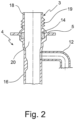
- the article in the form of the filling tube 4 is in figure 2 shown.
- the filler pipe comprises the main pipe, designated 16, which defines a fueling channel into a container, and the secondary pipe, designated 12, which forms a vent line.
- the filling tube 4 includes the filling head 5 with a mouth hole socket 18 which is provided with an external thread 19 .
- the mouth hole socket 18 encloses a filling channel 20 which extends from the mouth hole socket 18 through the filling head 5 into the main pipe 16 .
Landscapes
- Engineering & Computer Science (AREA)
- Mechanical Engineering (AREA)
- Manufacturing & Machinery (AREA)
- Injection Moulding Of Plastics Or The Like (AREA)
- Moulds For Moulding Plastics Or The Like (AREA)
Description
Die Erfindung betrifft ein Verfahren zur Herstellung eines rohrförmigen Bauteils als Artikel aus thermoplastischem Kunststoff unter Verwendung einer Spritzgießvorrichtung. Die Erfindung betrifft weiterhin eine Spritzgießvorrichtung zur Herstellung eines solchen rohrförmigen Bauteils.The invention relates to a method for producing a tubular component as an article made of thermoplastic material using an injection molding device. The invention also relates to an injection molding device for producing such a tubular component.
Die Erfindung betrifft insbesondere ein Verfahren zur Herstellung eines Artikels als Rohr oder Rohrstutzen eines Flüssigkeitsbehälters.In particular, the invention relates to a method for producing an article as a pipe or pipe socket of a liquid container.
Insbesondere Einfüllrohre für Kraftstoffbehälter oder für Additivbehälter für Kraftfahrzeuge werden heutzutage in Teilstücken blasgeformt oder vulkanisiert und dann aus einzelnen Teilstücken zusammengesetzt. Der Einfüllrohr-Kopf wird als Spritzgußschweißgruppe am oberen Ende eines beispielsweise extrusionsblasgeformten Rohres montiert. Seitlich angebundene Belüftungsleitungen werden auf angeschweißten Nippeln befestigt. Die Herstellung eines Einfüllrohrs in der vorstehend beschriebenen Art und Weise ist verhältnismäßig aufwendig. Bei jeder Montage und bei jeder Schweißung entstehen Kosten. Nach Zusammenbau des Einfüllrohrs muss dieses auf Dichtigkeit überprüft werden, was weitere Kosten verursacht.In particular, filler pipes for fuel tanks or for additive tanks for motor vehicles are nowadays blow-molded or vulcanized in sections and then assembled from individual sections. The filler pipe head is assembled as an injection weld assembly at the top end of a pipe, for example extrusion blow molded. Ventilation lines connected to the side are fastened to welded nipples. The production of a filler pipe in the manner described above is relatively expensive. Every assembly and every weld generates costs. After the filler pipe has been assembled, it must be checked for leaks, which incurs additional costs.
Aus der
Aus der
Aus der
Aus der
Ein Verfahren zur Herstellung eines durch einen Gewebeschlauch verstärkten Kunststoffschlauchs unter Verwendung von einem Projektilinjektionsverfahren ist aus der
Aus der
Ein Verfahren zur Herstellung eines rohrförmigen Kunststoffteils ist weiterhin aus der
Aus der
Der Erfindung liegt die Aufgabe zugrunde, ein Verfahren zur Herstellung eines rohrförmigen Bauteils als Artikel aus thermoplastischem Kunststoff unter Verwendung einer Spritzgießvorrichtung bereitzustellen, welches gegenüber den bislang bekannten Verfahren vereinfacht ist. Insbesondere soll die Herstellung eines komplexen rohrförmigen Bauteils, beispielsweise als Rohrstutzen oder Stutzengehäuse mit einem Befüllkanal in möglichst wenigen Arbeitsschritten möglich sein.The invention is based on the object of using a method for producing a tubular component as an article made of thermoplastic material provide an injection molding device, which is simplified compared to the previously known method. In particular, the production of a complex tubular component, for example as a pipe socket or socket housing with a filling channel, should be possible in as few work steps as possible.
Der Erfindung liegt weiterhin die Aufgabe zugrunde, eine entsprechende Spritzgießvorrichtung bereitzustellen.The invention is also based on the object of providing a corresponding injection molding device.
Die der Erfindung zugrundeliegende Aufgabe wird gelöst durch die Merkmale des Anspruchs 1. Vorteilshafte Ausgestaltungen des Verfahrens ergeben sich aus den Unteransprüchen.The object on which the invention is based is achieved by the features of
Die der Erfindung zugrundeliegende Aufgabe wird weiterhin gelöst durch eine Spritzgießvorrichtung mit den Merkmalen des Anspruchs 9. Vorteilhafte Ausgestaltungen der Spritzgießvorrichtung ergeben sich aus den auf Anspruch 9 zurückbezogenen Unteransprüchen.The object on which the invention is based is further achieved by an injection molding device having the features of
Nach einem Gesichtspunkt der Erfindung ist ein Verfahren zur Herstellung eines rohrförmigen Bauteils als Artikel aus thermoplastischem Kunststoff vorgesehen, unter Verwendung einer Spritzgießvorrichtung mit einem eine Artikelkavität bildenden Werkzeug, mit Mitteln zum Füllen der Artikelkavität mit einer thermoplastischen Formmasse und mit einer Injektionsvorrichtung zur Injektion eines Fluids in die Artikelkavität, wobei die Injektionsvorrichtung einen Düsenkörper umfasst, wobei das Verfahren vorsieht, dass der Düsenkörper als Formkern zur Ausformung eines Endes des Artikels verwendet wird und dass der Düsenkörper als Träger für ein in den Artikel einzubringendes Zusatzbauteil verwendet wird, wobei,
- a) der Düsenkörper zunächst mit dem Zusatzbauteil bestückt wird,
- b) der Düsenkörper in die geschlossene Artikelkavität eingeführt wird oder das Werkzeug um den Düsenkörper geschlossen wird,
- c) die Artikelkavität in einem weiteren Verfahrensschritt zumindest teilweise mit der thermoplastischen Formmasse gefüllt wird,
- d) sodann mittels der Injektionsvorrichtung ein unter Druck stehendes Fluid in die Artikelkavität eingeleitet wird, wobei ein Teil der Formmasse in eine Nebenkavität oder in ein anderes Volumen verdrängt wird und
- e) der Artikel entformt wird.
- a) the nozzle body is first fitted with the additional component,
- b) the nozzle body is inserted into the closed article cavity or the tool is closed around the nozzle body,
- c) the article cavity is at least partially filled with the thermoplastic molding compound in a further process step,
- d) a pressurized fluid is then introduced into the article cavity by means of the injection device, part of the molding material being displaced into a secondary cavity or into another volume and
- e) the article is demoulded.
Vorzugsweise werden die Verfahrensschritte a) bis e) in der Reihenfolge ihrer Aufzählung durchgeführt, wobei nicht ausgeschlossen ist, dass das Verfahren jeweils noch Zwischenschritte umfasst.Process steps a) to e) are preferably carried out in the order in which they are listed, it not being ruled out that the process also includes intermediate steps in each case.
Eine thermoplastische Formmasse im Sinne der vorliegenden Erfindung ist ein plastifizierter thermoplastischer Kunststoff, der beispielsweise der Spritzgießvorrichtung bzw. dem Werkzeug mittels eines Extruders über einen Anguss zugeführt wird.A thermoplastic molding compound within the meaning of the present invention is a plasticized thermoplastic material that is fed, for example, to the injection molding device or the tool by means of an extruder via a sprue.
Die Nebenkavität kann beispielsweise mittels eines oder mehrerer Schieber bis zum teilweise oder vollständigen Füllen der Artikelkavität zugehalten werden, vorzugsweise wird der Schieber dann nach dem Verfahrensschritt c) geöffnet, so dass das unter Druck stehende Fluid eine schmelzeflüssige Seele der Formmasse in die Nebenkavität verdrängt, wobei der nicht verdrängte Teil der Formmasse eine stehengebliebene Artikelwand bildet.The secondary cavity can be closed, for example, by means of one or more slides until the article cavity is partially or completely filled; the slide is then preferably opened after method step c), so that the pressurized fluid forces a molten core of the molding compound into the secondary cavity, wherein the non-displaced part of the molding compound forms a standing article wall.
Alternativ kann die Formmasse in ein anderes Volumen verdrängt werden. Hierzu kann beispielsweise vorgesehen sein, die Formmasse in einen Extruder zurückzufördern, der zur Bereitstellung der Formmasse verwendet wurde.Alternatively, the molding compound can be displaced into another volume. For this purpose, provision can be made, for example, for the molding compound to be conveyed back into an extruder that was used to prepare the molding compound.
Als thermoplastische Formmasse im Sinne der Erfindung kann jedes beliebige thermoplastische Polymer vorgesehen sein. Beispielsweise kann als thermoplastische Formmasse ein thermoplastischer Kunststoff vorgesehen sein, der ausgewählt ist aus einer Gruppe umfassend Polyethylen hoher Dichte, Polyamid, Polyamid 6, Polyamid 12, Polyurethan, Polycarbonat, Acrylnitril-Butadien-Styrol-Copolymerisat, Polyketone, Polystyrol, thermoplastische Elastomere auf Olefinbasis, vernetzte thermoplastische Elastomere auf Olefinbasis, thermoplastische Elastomere auf Urethanbasis, thermoplastische Polyesterelastomere und thermoplastische Copolymere.Any desired thermoplastic polymer can be provided as the thermoplastic molding compound within the meaning of the invention. For example, a thermoplastic can be provided as the thermoplastic molding compound, which is selected from a group comprising high-density polyethylene, polyamide, polyamide 6,
Nach dem erfindungsgemäßen Verfahren ist vorgesehen, dass der Düsenkörper an einem Ende der Artikelkavität, die ein Negativ des rohrförmigen Bauteils bildet, die Artikelkavität verschließt und abdichtet, wobei der Düsenkörper in die Artikelkavität eintaucht und dort mit der Artikelkavität einen mit der thermoplastischen Formmasse füllbaren Hohlraum, vorzugsweise einen Ringraum ausbildet. Bevor der Düsenkörper in die Artikelkavität verbracht wird, wird dieser zweckmäßigerweise mit dem in den Artikel einzubringenden Zusatzbauteil bestückt. Beispielsweise kann vorgesehen sein, dass zunächst das beispielsweise zweiteilige Werkzeug geöffnet wird, der Düsenkörper bei geöffnetem Werkzeug mit dem Zusatzbauteil bestückt wird und sodann das Werkzeug um den Düsenkörper geschlossen wird.According to the method according to the invention, it is provided that the nozzle body closes and seals the article cavity at one end of the article cavity, which forms a negative of the tubular component, with the nozzle body dipping into the article cavity and there forming a hollow space that can be filled with the thermoplastic molding compound with the article cavity, preferably forms an annular space. Before the nozzle body is brought into the article cavity, it is expediently equipped with the additional component to be introduced into the article. For example, it can be provided that first the two-part tool, for example, is opened, the nozzle body is equipped with the additional component when the tool is open, and then the tool is closed around the nozzle body.
Alternativ oder zusätzlich kann der Düsenkörper relativ zu dem Werkzeug verstellbar angeordnet sein, und zwar zwischen einer formgebenden ersten Stellung und einer entformten zweiten Stellung.Alternatively or additionally, the nozzle body can be arranged to be adjustable relative to the tool, specifically between a shaping first position and a demolded second position.
Vorzugsweise wird der Düsenkörper bzw. der Formkern vor dem Entformen des Artikels, d.h. vor dem Verfahrensschritt e) aus dem Werkzeug herausgezogen, also in eine zweite entformte Stellung verbracht.The nozzle body or the mold core is preferably pulled out of the mold before the article is removed from the mold, i.e. before method step e), i.e. brought into a second demolded position.
Zweckmäßigerweise ist der Düsenkörper als Projektilträger zur Aufnahme eines Projektils ausgebildet, wobei vor dem Verfahrensschritt d) der Düsenkörper mit wenigstens einem Projektil bestückt wird und wobei das mittels der Injektionsvorrichtung eingeleitete Fluid das Projektil unter Verdrängung einer schmelzeflüssigen Seele der Formmasse durch die Artikelkavität treibt. Als Fluid kann Wasser aber auch beispielsweise ein Gas Anwendung finden.The nozzle body is expediently designed as a projectile carrier for receiving a projectile, with the nozzle body being fitted with at least one projectile before process step d) and with the fluid introduced by means of the injection device driving the projectile through the article cavity, displacing a molten core of the molding compound. However, water, for example a gas, can also be used as the fluid.
Zweckmäßigerweise wird bei dem Verfahren gemäß der Erfindung das Zusatzbauteil in die thermoplastische Formmasse eingebettet. Das Zusatzbauteil kann beispielsweise stoffschlüssig und/oder formschlüssig mit der thermoplastischen Formmasse verbunden werden.In the method according to the invention, the additional component is expediently embedded in the thermoplastic molding compound. The additional component can, for example, be connected to the thermoplastic molding compound in a material-to-material and/or form-fitting manner.
Bei einer bevorzugten Variante des Verfahrens gemäß der Erfindung ist vorgesehen, dass der Düsenkörper nach dem Verfahrensschritt d) und vor dem Verfahrensschritt e) aus der Artikelkavität gezogen wird, so dass das Zusatzbauteil in dem Artikel verbleibt. Das Zusatzbauteil kann beispielsweise als permanentmagnetischer Ring ausgebildet sein, der während des Verfahrensschritts a) auf den Düsenkörper lösbar aufgesteckt wird.In a preferred variant of the method according to the invention it is provided that the nozzle body is pulled out of the article cavity after method step d) and before method step e), so that the additional component remains in the article. The additional component can be designed, for example, as a permanent magnetic ring that is detachably slipped onto the nozzle body during method step a).
Nach einer bevorzugten Variante des Verfahrens gemäß der Erfindung ist vorgesehen, dass der Artikel als Rohr oder Rohrstutzen eines Flüssigkeitsbehälters ausgeformt wird, der einen Befüllkanal definiert. Der Rohrstutzen kann beispielsweise als erfindungsgemäß einteilig ausgebildetes Stutzengehäuse eines Einfüllrohres, beispielsweise für einen Nebenflüssigkeitsbehälter eines Kraftfahrzeuges oder für einen Kraftstoffbehälter eines Kraftfahrzeuges ausgebildet sein. Gemäß dem Verfahren kann vorgesehen sein, dass Stutzengehäuse und einen sich an dieses anschließenden Rohrabschnitt vollständig einstückig auszubilden.According to a preferred variant of the method according to the invention, it is provided that the article is shaped as a pipe or pipe socket of a liquid container which defines a filling channel. The pipe socket can, for example, be designed as a one-piece socket housing of a filler pipe, for example for an auxiliary liquid tank of a motor vehicle or for a fuel tank of a motor vehicle. According to the method, provision can be made for the connection piece housing and a pipe section adjoining it to be designed completely in one piece.
Erfindungsgemäß ist vorzugsweise vorgesehen, dass das Rohr, der Rohrstutzen oder das Rohrgehäuse mit einem verlorenen Zusatzbauteil, beispielsweise in Form eines Ringmagneten hergestellt wird. Ein solcher Ringmagnet bewirkt beispielsweise die Betätigung eines in einem Zapfventil vorgesehenen Schaltventils.According to the invention, it is preferably provided that the tube, the tube socket or the tube housing is produced with a lost additional component, for example in the form of a ring magnet. Such a ring magnet causes, for example, the actuation of a switching valve provided in a dispensing valve.
Bei einer zweckmäßigen Variante des Verfahrens der Erfindung ist vorgesehen, eine innere Begrenzungswand des Artikels, beispielsweise eine den Befüllkanal begrenzende Wand in Längsrichtung zu profilieren. Wenn die innere Begrenzungswand des Artikels einen Befüllkanal bildet, kann dieser beispielsweise mit Längsrippen versehen sein, die dazu dienen können, ein in den Befüllkanal einzusetzendes Zapfventil zu zentrieren und eine Gegenstromentlüftung bei der Befüllung zuzulassen.In an expedient variant of the method of the invention, provision is made for an inner boundary wall of the article, for example a wall bounding the filling channel, to be profiled in the longitudinal direction. If the inner boundary wall of the article forms a filling channel, this can be provided with longitudinal ribs, for example, which can serve to insert a filling channel into the filling channel Center the nozzle and allow counterflow venting when filling.
Bei einer bevorzugten Variante des Verfahrens ist vorgesehen, dass die innere Begrenzungswand des Artikels mit wenigstens einer Einschnürung ausgebildet wird, die beispielsweise, wenn die innere Begrenzungswand des Artikels einen Befüllkanal eines Rohres oder Rohrstutzens definiert, als Einschubbegrenzungsanschlag für ein Zapfventil dienen kann.In a preferred variant of the method it is provided that the inner boundary wall of the article is formed with at least one constriction which, for example, can serve as an insertion limit stop for a nozzle if the inner boundary wall of the article defines a filling channel of a pipe or pipe socket.
Die der Erfindung zugrundeliegende Aufgabe wird weiterhin gelöst durch eine Spritzgießvorrichtung zur Herstellung eines rohrförmigen Bauteils als Artikel aus thermoplastischem Kunststoff, insbesondere zur Durchführung des zuvor beschriebenen Verfahrens, mit einem eine Artikelkavität bildenden Werkzeug, mit Mitteln zum Füllen der Artikelkavität mit einer thermoplastischen Formmasse, mit wenigstens einer Injektionsvorrichtung zur Injektion eines Fluids in die Artikelkavität, wobei die Injektionsvorrichtung einen Düsenkörper umfasst, der wenigstens einen Fluidkanal aufweist, der mit einem unter Druck stehenden Fluid beschickbar ist, wobei der Düsenkörper als Formkern zur Ausformung eines Endes des Artikels ausgebildet ist.The object on which the invention is based is also achieved by an injection molding device for producing a tubular component as an article made of thermoplastic material, in particular for carrying out the method described above, with a tool forming an article cavity, with means for filling the article cavity with a thermoplastic molding compound, with at least an injection device for injecting a fluid into the article cavity, the injection device comprising a nozzle body which has at least one fluid channel which can be charged with a pressurized fluid, the nozzle body being designed as a mold core for shaping one end of the article.
Das Werkzeug kann beispielsweise zwei Formhälften aufweisen, die geschlossen eine Artikelkavität begrenzen. Die Artikelkavität kann beispielsweise ein Negativ eines Rohres oder eines Rohrstutzens definieren.The tool can have, for example, two mold halves which, when closed, delimit an article cavity. The article cavity can define, for example, a negative of a pipe or a pipe socket.
Als Mittel zum Füllen der Artikelkavität kann wenigstens eine Extrusionsvorrichtung, beispielsweise ein Schubschneckenextruder vorgesehen sein.At least one extrusion device, for example a push screw extruder, can be provided as a means for filling the article cavity.
Der Düsenkörper bzw. der Formkern kann relativ zu dem Werkzeug verstellbar angeordnet sein, beispielsweise von einer ersten formgebenden Stellung, in der der Düsenkörper in die Artikelkavität eintaucht in eine zweite entformte Stellung, in der der Düsenkörper aus der Artikelkavität gezogen ist. Der Düsenkörper ist vorzugsweise an einem Ende der Artikelkavität angeordnet und dichtet diese in der ersten Stellung ab.The nozzle body or the mold core can be arranged so that it can be adjusted relative to the tool, for example from a first shaping position in which the nozzle body dips into the article cavity to a second demolded position in which the nozzle body is pulled out of the article cavity. The nozzle body is preferably arranged at one end of the article cavity and seals it off in the first position.
Der Düsenkörper bildet vorzugsweise in der Artikelkavität einen mit der Formmasse füllbaren Formhohlraum aus. Dieser Formhohlraum kann als Ringraum ausgebildet sein, grundsätzlich sind allerdings mit der Spritzgießvorrichtung gemäß der Erfindung sowie mit dem Verfahren gemäß der Erfindung auch rohrförmige Bauteile mit einem vieleckigen bzw. prismatischen Querschnitt herstellbar. Der Begriff "rohrförmig" ist grundsätzlich nicht auf einen zylindrischen Querschnitt beschränkt.The nozzle body preferably forms a mold cavity in the article cavity that can be filled with the molding compound. This mold cavity can be designed as an annular space, but in principle tubular components with a polygonal or prismatic cross section can also be produced with the injection molding device according to the invention and with the method according to the invention. In principle, the term "tubular" is not limited to a cylindrical cross-section.
Das Werkzeug gemäß der Erfindung kann einen oder mehrere Angüsse aufweisen. Darüber hinaus kann das Werkzeug gemäß der Erfindung weitere bewegliche Formteile wie Schieber, bewegliche Formkerne und dergleichen aufweisen. Die Artikelkavität des Werkzeugs steht zweckmäßigerweise in Verbindung mit einer Nebenkavität, die die verdrängte Formmasse aufnimmt. Die Nebenkavität kann beispielsweise mittels eines oder mehrerer, beispielsweise hydraulisch betätigbarer Schieber von der Artikelkavität trennbar sein. Alternativ kann vorgesehen sein, einen Anguss an einem von der Injektionsvorrichtung abliegenden Ende der Artikelkavität vorzusehen und das Volumen eines Extruders als Nebenkavität zu nutzen.The tool according to the invention can have one or more gates. In addition, the tool according to the invention can have other movable mold parts such as slides, movable mold cores and the like. The article cavity of the tool is expediently connected to a secondary cavity which accommodates the displaced molding compound. The secondary cavity can be separated from the article cavity, for example, by means of one or more slides that can be actuated hydraulically, for example. Alternatively, provision can be made to provide a sprue at an end of the article cavity remote from the injection device and to use the volume of an extruder as a secondary cavity.
Die Injektionsvorrichtung gemäß der Erfindung ist zur Injektion eines unter Hochdruck stehenden Fluids, beispielsweise zur Injektion von Wasser in die Artikelkavität ausgebildet, wobei der Düsenkörper mit einem oder mehreren Fluidkanälen durchsetzt sein kann.The injection device according to the invention is designed for injecting a fluid under high pressure, for example for injecting water, into the article cavity, it being possible for the nozzle body to be interspersed with one or more fluid channels.
Bei einer bevorzugten Variante der Spritzgießvorrichtung gemäß der Erfindung ist vorgesehen, dass der Düsenkörper als Projektilträger zur Aufnahme eines Projektils als Verdrängerkörper für die Formmasse ausgebildet ist. In diesem Fall ist die Spritzgießvorrichtung gemäß der Erfindung so ausgebildet, dass das unter Druck stehende Fluid gegen das Projektil injiziert wird, wobei das Fluid das Projektil durch die Artikelkavität treibt und das Projektil eine schmelzeflüssige Seele der Formmasse in die Nebenkavität oder ein anderes Volumen verdrängt. Das Projektil besitzt zweckmäßigerweise einen Querschnitt, der kleiner als der Querschnitt der Artikelkavität ist, so dass eine Artikelwand stehen bleibt.In a preferred variant of the injection molding device according to the invention, it is provided that the nozzle body is designed as a projectile carrier for receiving a projectile as a displacement body for the molding compound. In this case, the injection molding apparatus according to the invention is arranged so that the pressurized fluid is injected against the projectile, the fluid propelling the projectile through the article cavity and the projectile displacing a molten core of the molding compound into the secondary cavity or other volume. The projectile expediently has a cross section that is smaller than the cross section of the article cavity, so that one wall of the article remains.
Der Düsenkörper weist erfindungsgemäß einen formgebenden Schaft auf, der mit der Artikelkavität einen mit der Formmasse befüllbaren Hohlraum bildet. Wie eingangs bereits erwähnt, kann dieser Hohlraum als Ringraum aber auch als vieleckige Kontur vorgesehen sein.According to the invention, the nozzle body has a shaping shaft which, together with the article cavity, forms a cavity that can be filled with the molding compound. As already mentioned at the outset, this hollow space can be provided as an annular space, but also as a polygonal contour.
Erfindungsgemäß ist der Schaft profiliert, so dass die innere Begrenzungswand des Artikels dadurch ebenso in Längsrichtung profiliert wird, so dass beispielsweise, wenn der Artikel als Rohr oder Rohrstutzen ausgebildet ist, dessen Wand mit in den Querschnitt des Befüllkanals vorstehenden Rippen ausgeformt wird.According to the invention, the shaft is profiled so that the inner boundary wall of the article is also profiled in the longitudinal direction, so that, for example, if the article is designed as a pipe or pipe socket, its wall is formed with ribs protruding into the cross section of the filling channel.
Zweckmäßigerweise weist der Schaft einen ersten größeren und einen zweiten kleineren Querschnitt auf und verjüngt sich in Richtung auf distales Ende. Das proximale Ende des Schaftes dichtet zweckmäßigerweise die Artikelkavität ab. Das distale Ende des Schafts ist dasjenige Ende des Schafts, welches stromabwärts des injizierten Fluids angeordnet ist.The shaft expediently has a first larger and a second smaller cross-section and tapers in the direction of the distal end. The proximal end of the stem suitably seals the article cavity. The distal end of the shaft is that end of the shaft which is downstream of the fluid being injected.
Zweckmäßigerweise ist das distale Ende des Schafts als Projektilaufnahme ausgebildet. Das Projektil kann beispielsweise einen Querschnitt haben, der größer als der zweite Querschnitt ist, so dass aufgrund dieser Ausgestaltung die innere Begrenzungswand des Artikels mit einer Einschnürung herstellbar ist. Das Projektil bildet dabei in besonders bevorzugter Art und Weise innerhalb der Artikelkavität einen mit der Formmasse befüllbaren Hinterschnitt.The distal end of the shaft is expediently designed as a projectile receptacle. The projectile can, for example, have a cross section that is larger than the second cross section, so that the inner boundary wall of the article can be produced with a constriction due to this configuration. In a particularly preferred manner, the projectile forms an undercut within the article cavity that can be filled with the molding compound.
Das Verfahren gemäß der Erfindung kann vorsehen, dass mittels weiterer Projektile Verzweigungen des als Rohr auszuformenden Artikels hergestellt werden.The method according to the invention can provide that branches of the article to be shaped as a tube are produced by means of further projectiles.
Darüber hinaus kann vorgesehen sein, dass der Düsenkörper als Projektilträger für mehrere Projektile ausgebildet sein kann, wobei beispielsweise ein erstes Projektil ein Hauptrohr und ein zweites Projektil ein Nebenrohr formt.In addition, it can be provided that the nozzle body can be designed as a projectile carrier for several projectiles, with a first projectile forming a main tube and a second projectile forming a side tube, for example.
Die Erfindung wird nachstehend anhand eines in den Zeichnungen dargestellten Ausführungsbeispiels erläutert.The invention is explained below with reference to an embodiment shown in the drawings.
Es zeigen:
- Fig. 1
- einen schematischen Teilschnitt durch eine Spritzgießvorrichtung gemäß der Erfindung und
- Fig. 2
- einen Teilschnitt durch ein Einfüllrohr für einen Harnstoffbehälter eines KFZ, welches mit dem Verfahren gemäß der Erfindung unter Verwendung des Werkzeugs gemäß der Erfindung hergestellt wurde.
- 1
- a schematic partial section through an injection molding device according to the invention and
- 2
- a partial section through a filler pipe for a urea tank of a motor vehicle, which was produced with the method according to the invention using the tool according to the invention.
Die Spritzgießvorrichtung 1 nach der Erfindung umfasst einen nur andeutungsweise dargestelltes Werkzeug 2, welches beispielsweise aus zwei Formhälften besteht, die eine Artikelkavität 3 definieren. Die Artikelkavität 3 kann beispielsweise als Negativ des in
Die
Die Spritzgießvorrichtung 1 umfasst weiterhin eine Injektionsvorrichtung 6, die einen Düsenkörper 7 umfasst. Die Injektionsvorrichtung 6 ist in
Der Düsenkörper 7 ist von einer ersten formgebenden Stellung in eine zweite entformte Stellung relativ zu dem Werkzeug 2 bewegbar, wobei
Der Düsenkörper 7 ist erfindungsgemäß als Formkern sowie als Projektilträger zur Aufnahme eines Projektils 8 aus thermoplastischem Kunststoff ausgebildet. Der Düsenkörper 7 umfasst einen Schaft 9, der ein proximales Ende und ein distales Ende aufweist, wobei das proximale Ende die Artikelkavität 3 abdichtet und das distale Ende das Projektil 8 aufnimmt.According to the invention, the
An seinem proximalen Ende hat der Schaft 9 einen ersten größeren Durchmesser, an seinem distalen Ende hat der Schaft 9 einen zweiten kleineren Durchmesser. Im Bereich des ersten Durchmessers ist der Schaft 9 mit sich in Längsrichtung erstreckenden Nuten 10 versehen, die entsprechende Rippen in einer inneren Begrenzungswand des herzustellenden Artikels ausprägen.The
Der Schaft 9 bildet mit der Artikelkavität 3 einen Ringraum, der über einen in der Zeichnung nicht dargestellten Anguss mit einer thermoplastischen Formmasse befüllbar ist.The
Der Anguss ist in der Zeichnung nicht dargestellt, dieser befindet sich bezogen auf die Vorschubrichtung des Projektils 8 stromabwärts.The sprue is not shown in the drawing; it is located downstream in relation to the direction of advance of the
Bei dem in
Der Düsenkörper 7 ist mit einem Fluidkanal 15 durchsetzt, durch den ein unter Hochdruck stehendes Fluid in die Artikelkavität 3 eingeleitet werden kann. Der Fluidkanal 15 verzweigt sich einerseits zu dem distalen Ende des Schaftes 9, wo dieser sich in Richtung auf das Projektil 8 öffnet und andererseits zur Seite in Richtung auf das zweite Projektil 13. Über den Fluidkanal 15 wird das Fluid, beispielsweise Wasser unter Druck gegen das Projektil 8 und gegen das zweite Projektil 13 getrieben, wobei das Projektil 8 und das zweite Projektil 13 durch den Druck des Fluids getrieben die in der Artikelkavität 3 befindliche plastische Formmasse in die Nebenkavität verdrängen.The
Das auf das distale Ende des Schafts 9 aufgesteckte Projektil 8 hat einen maximalen Außendurchmesser, der größer als der zweite Durchmesser des Schafts ist, so dass das Projektil 8 einen temporären Hinterschnitt des Düsenkörpers 7 bildet, der mit der Formmasse befüllbar ist.The projectile 8 placed on the distal end of the
Auf den Schaft 9 des Düsenkörpers 7 ist weiterhin im Bereich des ersten Durchmessers ein Zusatzbauteil in Form eines Ringmagneten 14 aufgesteckt, welcher mit dem Düsenkörper 7 in die Artikelkavität 3 vor deren Füllung mit der thermoplastischen Formmasse verbracht wird.In the region of the first diameter, an additional component in the form of a
Bei dem Verfahren gemäß der Erfindung wird beispielsweise zunächst das Werkzeug 2 geschlossen, sodann wird der Düsenkörper 7 mit dem auf den Schaft 9 lösbar aufgesteckten Ringmagneten 14 von einer zweiten Entformungsstellung in eine erste formgebende Stellung verbracht, in der der Schaft 9 in die Artikelkavität 3 eintaucht und diese abdichtet. Sodann wird die Artikelkavität 3 über einen oder mehrere nicht dargestellten Angüsse mit der thermoplastischen Formmasse gefüllt. Die Füllung kann ganz oder teilweise erfolgen. Die thermoplastische Formmasse füllt die Artikelkavität auch im Bereich des zwischen dem Düsenkörper 7 und dem Werkzeug 2 gebildeten Formhohlraums 17, wobei die thermoplastische Formmasse den Ringmagneten 14 umschließt und einbettet. Weiterhin hinterfließt die thermoplastische Formmasse das Projektil 8, da der Durchmesser des Schafts 9 (zweiter Durchmesser) unmittelbar stromaufwärts des Projektils 8 kleiner als der maximale Durchmesser des Projektils 8 ist.In the method according to the invention, for example, the tool 2 is first closed, then the
Nach dem Füllen der Artikelkavität 3 mit der thermoplastischen Formmasse wird die nicht gezeigte Nebenkavität beispielsweise über hydraulisch betätigbare Schieber freigegeben.After the
In einem weiteren Verfahrensschritt wird sodann ein unter Druck stehendes Fluid, beispielsweise Wasser, durch den Fluidkanal 15 gegen das Projektil 8 sowie gegen das zweite Projektil 13 getrieben. Das Fluid treibt die Projektile 8, 13 durch die Artikelkavität 3, wobei das Projektil 8 ein Hauptrohr 16 und das zweite Projektil 13 das Nebenrohr 12 ausformt. Die Projektile 8, 13 verdrängen eine schmelzeflüssige Seele der Formmasse, stehen bleibt die Restwand/Begrenzungswand des als Einfüllrohr 4 ausgebildeten Rohres.In a further method step, a pressurized fluid, for example water, is then driven through the
In einem weiteren Verfahrensschritt wird der Düsenkörper 7 in eine zweite entformte, d.h. zurückgezogene Stellung verfahren, wobei der Ringmagnet 14 in der eingefüllten Formmasse verbleibt.In a further process step, the
Anschließend wird der Artikel entformt. Der Artikel in Form des Einfüllrohres 4 ist in
- 11
- Spritzgießvorrichtunginjection molding device
- 22
- WerkzeugTool
- 33
- Artikelkavitätarticle cavity
- 44
- Einfüllrohrfilling tube
- 55
- Einfüllkopffilling head
- 66
- Injektionsvorrichtunginjection device
- 77
- Düsenkörpernozzle body
- 88th
- Projektilprojectile
- 99
- Schaftshaft
- 1010
- Nutengrooves
- 1111
- Verzweigungbranch
- 1212
- Nebenrohrsecondary pipe
- 1313
- zweites Projektilsecond projectile
- 1414
- Ringmagnetring magnet
- 1515
- Fluidkanalfluid channel
- 1616
- Hauptrohrmain pipe
- 1717
- Formhohlraummold cavity
- 1818
- Mundlochstutzenlip socket
- 1919
- Außengewindeexternal thread
- 2020
- Befüllkanalfilling channel
Claims (12)
- A method for producing a tubular component as an article from a thermoplastic material while using an injection-molding device (1) having a tool (2) that forms an article cavity (3), having means for filling the article cavity (3) with a thermoplastic molding compound, and having an injection device (6) for injecting a fluid into the article cavity (3), wherein the injection device (6) comprises a nozzle body (7), wherein the method provides that the nozzle body (7) is used as a mold core for molding the shape of an end of the article; that the nozzle body (7) is used as a carrier for an additional component that is to be incorporated into the article; whereina) the nozzle body (7) is first equipped with the additional component;b) the nozzle body (7) is introduced into the closed article cavity (3), or the tool (2) is closed around the nozzle body (7);c) the article cavity (3) in a further method step is at least partially filled with the thermoplastic molding compound;d) a pressurized fluid is then induced into the article cavity (3) by means of the injection device (6), wherein part of the molding compound is displaced into a secondary cavity or another volume; ande) the article is de-molded.
- The method as claimed in claim 1, characterized in that the nozzle body (7) is configured as a projectile carrier for receiving a projectile (8), in that the nozzle body (7) prior to method step b) is equipped with at least one projectile (8), and in that the fluid that has been induced by means of the injection device (6) drives the projectile (8) through the article cavity (3) while displacing a molten core of the molding compound.
- The method as claimed in either of claims 1 and 2, characterized in that the additional component is embedded into the thermoplastic molding compound.
- The method as claimed in one of claims 1 to 3, characterized in that the nozzle body (7) after method step d) and prior to method step e) is pulled out of the article cavity (3) such that the additional component remains in the article.
- The method as claimed in one of claims 1 to 4, characterized in that the additional component is configured as a permanently magnetic ring (14) which is releasably plug-fitted onto the nozzle body (7).
- The method as claimed in one of claims 1 to 5, characterized in that the article is molded in the shape of a tube or tube connector of a liquids container which defines a filling duct (20).
- The method as claimed in one of claims 1 to 6, characterized in that an internal delimitation wall of the article in the longitudinal direction is profiled such that said article is preferably provided with longitudinal ribs.
- The method as claimed in one of claims 1 to 7, characterized in that the internal delimitation wall of the article is configured with at least one constriction.
- An injection-molding device for carrying out the method as claimed in one of claims 1 to 8, having a tool (2) that forms an article cavity (3), having means for filling the article cavity (3) with a thermoplastic molding compound, having at least one injection device (6) for injecting a fluid into the article cavity (3), wherein the injection device (6) comprises a nozzle body (7) which has at least one fluid duct (15) which is capable of being supplied with a pressurized fluid, wherein the nozzle body (7) is configured as a mold core for molding the shape of an end of the article, wherein the nozzle body (7) is suitable as a carrier for an additional component that is to be incorporated into the article, wherein the nozzle body (7) has a shape-imparting shank (9) which conjointly with the article cavity (3) forms a molding cavity (17), characterized in that the shank (9) is profiled in longitudinal direction.
- The injection-molding device as claimed in claim 9, characterized in that the nozzle body (7) is configured as a projectile carrier for receiving a projectile (8) as the displacement member for the molding compound.
- The injection-molding device as claimed in either of claims 9 or 10, characterized in that the shank (9) has a first comparatively large and a second comparatively small cross section, and in that the shank (9) tapers off in the direction toward a distal end.
- The injection-molding device as claimed in claim 11, characterized in that the distal end is configured as a projectile receptacle, and in that the projectile (8) has a cross section that is larger than the second cross section.
Applications Claiming Priority (2)
| Application Number | Priority Date | Filing Date | Title |
|---|---|---|---|
| DE102016200484.0A DE102016200484C5 (en) | 2016-01-15 | 2016-01-15 | Method and device for producing a tubular component from thermoplastic material by injection molding |
| PCT/EP2017/050434 WO2017121738A1 (en) | 2016-01-15 | 2017-01-11 | Method and device for producing a tube from thermoplastic synthetic material via injection moulding |
Publications (2)
| Publication Number | Publication Date |
|---|---|
| EP3402646A1 EP3402646A1 (en) | 2018-11-21 |
| EP3402646B1 true EP3402646B1 (en) | 2023-03-08 |
Family
ID=57838368
Family Applications (1)
| Application Number | Title | Priority Date | Filing Date |
|---|---|---|---|
| EP17700639.2A Active EP3402646B1 (en) | 2016-01-15 | 2017-01-11 | Method and device for producing a tube from thermoplastic synthetic material via injection moulding |
Country Status (5)
| Country | Link |
|---|---|
| US (1) | US10981308B2 (en) |
| EP (1) | EP3402646B1 (en) |
| CN (1) | CN109070417B (en) |
| DE (1) | DE102016200484C5 (en) |
| WO (1) | WO2017121738A1 (en) |
Families Citing this family (1)
| Publication number | Priority date | Publication date | Assignee | Title |
|---|---|---|---|---|
| CN113276340B (en) * | 2021-05-28 | 2023-05-05 | 上海延锋金桥汽车饰件系统有限公司 | Insert injection molding method and injection molding piece formed by insert injection molding method |
Family Cites Families (15)
| Publication number | Priority date | Publication date | Assignee | Title |
|---|---|---|---|---|
| JPS56121745A (en) | 1980-02-29 | 1981-09-24 | Toyoda Gosei Co Ltd | Foaming resin injection molding method |
| JP3204472B2 (en) | 1992-11-16 | 2001-09-04 | キョーラク株式会社 | Method for producing resin tubular body |
| US20020001634A1 (en) | 2000-06-29 | 2002-01-03 | Toshio Komazawa | Molding tool for molding with cylindrical core |
| JP2002137253A (en) | 2000-08-25 | 2002-05-14 | Mitsuboshi Belting Ltd | Mold device for injection molding |
| KR101321328B1 (en) * | 2006-03-06 | 2013-10-23 | 니혼 클로져 가부시키가이샤 | Composite spout and injection-forming apparatus for forming the composite spout |
| ATE423902T1 (en) | 2006-12-12 | 2009-03-15 | Magneti Marelli Powertrain Spa | ELECTROMAGNETIC FUEL INJECTION VALVE FOR A DIRECT INJECTION INTERNAL COMBUSTION ENGINE |
| JP5078408B2 (en) | 2007-03-30 | 2012-11-21 | 株式会社ホンダロック | Vehicle out-handle device |
| DE102008023473A1 (en) | 2008-05-14 | 2009-11-19 | Röchling Automotive AG & Co. KG | Calibrator for casting process with projectile injection (PIT) |
| DE102009001276B3 (en) | 2009-03-02 | 2010-07-15 | Geiger Automotive Gmbh | Method and device for producing a plastic part |
| DE102010015453B3 (en) | 2010-04-17 | 2011-06-22 | Wittmann Battenfeld Gmbh | Device and method for injection molding a molding having at least one cavity |
| DE102011009745B4 (en) | 2011-01-28 | 2012-09-13 | Kautex Textron Gmbh & Co. Kg | Filler neck for a secondary fluid tank |
| DE102011015522A1 (en) | 2011-03-30 | 2012-10-04 | Andreas Stihl Ag & Co. Kg | Plastic body and manufacturing plant for producing a plastic body |
| JP2012213919A (en) | 2011-03-31 | 2012-11-08 | Fuji Heavy Ind Ltd | Method of manufacturing tubular hollow molding and mold |
| DE102011100132B4 (en) * | 2011-04-30 | 2020-07-23 | Vereinigung zur Förderung des Instituts für Kunststoffverarbeitung in Industrie und Handwerk an der Rhein.-Westf. Technischen Hochschule Aachen e.V. | Process for the production of hollow polymeric bodies |
| DE102015102640A1 (en) | 2014-02-26 | 2015-08-27 | Geiger Automotive Gmbh | Production of a fabric hose reinforced plastic hose |
-
2016
- 2016-01-15 DE DE102016200484.0A patent/DE102016200484C5/en active Active
-
2017
- 2017-01-10 US US16/070,060 patent/US10981308B2/en active Active
- 2017-01-11 CN CN201780006402.4A patent/CN109070417B/en active Active
- 2017-01-11 WO PCT/EP2017/050434 patent/WO2017121738A1/en not_active Ceased
- 2017-01-11 EP EP17700639.2A patent/EP3402646B1/en active Active
Also Published As
| Publication number | Publication date |
|---|---|
| CN109070417B (en) | 2020-12-04 |
| WO2017121738A1 (en) | 2017-07-20 |
| DE102016200484A1 (en) | 2017-07-20 |
| US10981308B2 (en) | 2021-04-20 |
| CN109070417A (en) | 2018-12-21 |
| US20180354172A1 (en) | 2018-12-13 |
| EP3402646A1 (en) | 2018-11-21 |
| DE102016200484B4 (en) | 2017-08-17 |
| DE102016200484C5 (en) | 2022-12-01 |
Similar Documents
| Publication | Publication Date | Title |
|---|---|---|
| DE2140311C3 (en) | Hose end piece and device for producing the same | |
| EP3389978B1 (en) | Method for producing a tube and injection-moulding device | |
| EP2377665B1 (en) | Device and method for injection moulding a moulded part comprising at least one cavity | |
| EP3308933B1 (en) | Device and method for manufacturing a tube head | |
| EP3377294B1 (en) | Injection moulding apparatus for manufacturing of pipes with inner threads and method of manufacturing such pipes | |
| DE102009031441A1 (en) | Method for producing an article made of thermoplastic material | |
| EP3389977B1 (en) | Injection-moulding device for producing multi-component mouldings and method for producing multi-component mouldings | |
| DE102008023473A1 (en) | Calibrator for casting process with projectile injection (PIT) | |
| EP3402646B1 (en) | Method and device for producing a tube from thermoplastic synthetic material via injection moulding | |
| WO2018095747A1 (en) | Method for producing a container | |
| EP3259110B1 (en) | Method for the extrusion blow moulding of a container of thermoplastic material and extrusion blow-moulded container | |
| WO2025067610A1 (en) | Shaped part made from injection-moulded plastic, method for producing the shaped part, insert for carrying out the method, and injection-moulding die for carrying out the method | |
| EP1005408A1 (en) | Method and device for injection moulding plastifiable parts | |
| DE102017204797A1 (en) | Method and device for producing a component made of thermoplastic material and component produced by the method | |
| EP2706271A1 (en) | Bellows and method for manufacturing same | |
| DE102012107045A1 (en) | Method for manufacturing applicator for liquid medium for e.g. writing application, involves expanding pipe up to system at mold walls of closed secondary and primary form jaws, and filling liquid medium into container by mandrel | |
| AT522894B1 (en) | Process for manufacturing a fuel tank | |
| WO2025202408A1 (en) | Injection moulding tool, and method for manufacturing a pedal crank for a bicycle | |
| DE4235776A1 (en) | Plastic tool for moulding plastic components and tool mfr. - has recesses for ejector unit created in tool by locating formers in mould used to cast plastic tool | |
| DE102013220990A1 (en) | Blow hose for internal pressure injection molding | |
| EP3405324A1 (en) | Method for injection-moulding a plastics component, and plastics component | |
| DE102013221008A1 (en) | Method for producing a plastic molding and device for producing a plastic molding | |
| WO2017125303A1 (en) | Method for injection-moulding a plastics component, and plastics component |
Legal Events
| Date | Code | Title | Description |
|---|---|---|---|
| STAA | Information on the status of an ep patent application or granted ep patent |
Free format text: STATUS: UNKNOWN |
|
| STAA | Information on the status of an ep patent application or granted ep patent |
Free format text: STATUS: THE INTERNATIONAL PUBLICATION HAS BEEN MADE |
|
| PUAI | Public reference made under article 153(3) epc to a published international application that has entered the european phase |
Free format text: ORIGINAL CODE: 0009012 |
|
| STAA | Information on the status of an ep patent application or granted ep patent |
Free format text: STATUS: REQUEST FOR EXAMINATION WAS MADE |
|
| 17P | Request for examination filed |
Effective date: 20180717 |
|
| AK | Designated contracting states |
Kind code of ref document: A1 Designated state(s): AL AT BE BG CH CY CZ DE DK EE ES FI FR GB GR HR HU IE IS IT LI LT LU LV MC MK MT NL NO PL PT RO RS SE SI SK SM TR |
|
| AX | Request for extension of the european patent |
Extension state: BA ME |
|
| DAV | Request for validation of the european patent (deleted) | ||
| DAX | Request for extension of the european patent (deleted) | ||
| STAA | Information on the status of an ep patent application or granted ep patent |
Free format text: STATUS: EXAMINATION IS IN PROGRESS |
|
| 17Q | First examination report despatched |
Effective date: 20191004 |
|
| GRAP | Despatch of communication of intention to grant a patent |
Free format text: ORIGINAL CODE: EPIDOSNIGR1 |
|
| STAA | Information on the status of an ep patent application or granted ep patent |
Free format text: STATUS: GRANT OF PATENT IS INTENDED |
|
| GRAS | Grant fee paid |
Free format text: ORIGINAL CODE: EPIDOSNIGR3 |
|
| INTG | Intention to grant announced |
Effective date: 20230103 |
|
| GRAA | (expected) grant |
Free format text: ORIGINAL CODE: 0009210 |
|
| STAA | Information on the status of an ep patent application or granted ep patent |
Free format text: STATUS: THE PATENT HAS BEEN GRANTED |
|
| AK | Designated contracting states |
Kind code of ref document: B1 Designated state(s): AL AT BE BG CH CY CZ DE DK EE ES FI FR GB GR HR HU IE IS IT LI LT LU LV MC MK MT NL NO PL PT RO RS SE SI SK SM TR |
|
| REG | Reference to a national code |
Ref country code: GB Ref legal event code: FG4D Free format text: NOT ENGLISH |
|
| REG | Reference to a national code |
Ref country code: CH Ref legal event code: EP Ref country code: AT Ref legal event code: REF Ref document number: 1552289 Country of ref document: AT Kind code of ref document: T Effective date: 20230315 |
|
| REG | Reference to a national code |
Ref country code: DE Ref legal event code: R096 Ref document number: 502017014478 Country of ref document: DE |
|
| REG | Reference to a national code |
Ref country code: IE Ref legal event code: FG4D Free format text: LANGUAGE OF EP DOCUMENT: GERMAN |
|
| REG | Reference to a national code |
Ref country code: LT Ref legal event code: MG9D |
|
| P01 | Opt-out of the competence of the unified patent court (upc) registered |
Effective date: 20230526 |
|
| REG | Reference to a national code |
Ref country code: NL Ref legal event code: MP Effective date: 20230308 |
|
| PG25 | Lapsed in a contracting state [announced via postgrant information from national office to epo] |
Ref country code: RS Free format text: LAPSE BECAUSE OF FAILURE TO SUBMIT A TRANSLATION OF THE DESCRIPTION OR TO PAY THE FEE WITHIN THE PRESCRIBED TIME-LIMIT Effective date: 20230308 Ref country code: NO Free format text: LAPSE BECAUSE OF FAILURE TO SUBMIT A TRANSLATION OF THE DESCRIPTION OR TO PAY THE FEE WITHIN THE PRESCRIBED TIME-LIMIT Effective date: 20230608 Ref country code: LV Free format text: LAPSE BECAUSE OF FAILURE TO SUBMIT A TRANSLATION OF THE DESCRIPTION OR TO PAY THE FEE WITHIN THE PRESCRIBED TIME-LIMIT Effective date: 20230308 Ref country code: LT Free format text: LAPSE BECAUSE OF FAILURE TO SUBMIT A TRANSLATION OF THE DESCRIPTION OR TO PAY THE FEE WITHIN THE PRESCRIBED TIME-LIMIT Effective date: 20230308 Ref country code: HR Free format text: LAPSE BECAUSE OF FAILURE TO SUBMIT A TRANSLATION OF THE DESCRIPTION OR TO PAY THE FEE WITHIN THE PRESCRIBED TIME-LIMIT Effective date: 20230308 Ref country code: ES Free format text: LAPSE BECAUSE OF FAILURE TO SUBMIT A TRANSLATION OF THE DESCRIPTION OR TO PAY THE FEE WITHIN THE PRESCRIBED TIME-LIMIT Effective date: 20230308 |
|
| PG25 | Lapsed in a contracting state [announced via postgrant information from national office to epo] |
Ref country code: SE Free format text: LAPSE BECAUSE OF FAILURE TO SUBMIT A TRANSLATION OF THE DESCRIPTION OR TO PAY THE FEE WITHIN THE PRESCRIBED TIME-LIMIT Effective date: 20230308 Ref country code: NL Free format text: LAPSE BECAUSE OF FAILURE TO SUBMIT A TRANSLATION OF THE DESCRIPTION OR TO PAY THE FEE WITHIN THE PRESCRIBED TIME-LIMIT Effective date: 20230308 Ref country code: GR Free format text: LAPSE BECAUSE OF FAILURE TO SUBMIT A TRANSLATION OF THE DESCRIPTION OR TO PAY THE FEE WITHIN THE PRESCRIBED TIME-LIMIT Effective date: 20230609 Ref country code: FI Free format text: LAPSE BECAUSE OF FAILURE TO SUBMIT A TRANSLATION OF THE DESCRIPTION OR TO PAY THE FEE WITHIN THE PRESCRIBED TIME-LIMIT Effective date: 20230308 |
|
| PG25 | Lapsed in a contracting state [announced via postgrant information from national office to epo] |
Ref country code: SM Free format text: LAPSE BECAUSE OF FAILURE TO SUBMIT A TRANSLATION OF THE DESCRIPTION OR TO PAY THE FEE WITHIN THE PRESCRIBED TIME-LIMIT Effective date: 20230308 Ref country code: RO Free format text: LAPSE BECAUSE OF FAILURE TO SUBMIT A TRANSLATION OF THE DESCRIPTION OR TO PAY THE FEE WITHIN THE PRESCRIBED TIME-LIMIT Effective date: 20230308 Ref country code: PT Free format text: LAPSE BECAUSE OF FAILURE TO SUBMIT A TRANSLATION OF THE DESCRIPTION OR TO PAY THE FEE WITHIN THE PRESCRIBED TIME-LIMIT Effective date: 20230710 Ref country code: EE Free format text: LAPSE BECAUSE OF FAILURE TO SUBMIT A TRANSLATION OF THE DESCRIPTION OR TO PAY THE FEE WITHIN THE PRESCRIBED TIME-LIMIT Effective date: 20230308 Ref country code: CZ Free format text: LAPSE BECAUSE OF FAILURE TO SUBMIT A TRANSLATION OF THE DESCRIPTION OR TO PAY THE FEE WITHIN THE PRESCRIBED TIME-LIMIT Effective date: 20230308 |
|
| PG25 | Lapsed in a contracting state [announced via postgrant information from national office to epo] |
Ref country code: SK Free format text: LAPSE BECAUSE OF FAILURE TO SUBMIT A TRANSLATION OF THE DESCRIPTION OR TO PAY THE FEE WITHIN THE PRESCRIBED TIME-LIMIT Effective date: 20230308 Ref country code: PL Free format text: LAPSE BECAUSE OF FAILURE TO SUBMIT A TRANSLATION OF THE DESCRIPTION OR TO PAY THE FEE WITHIN THE PRESCRIBED TIME-LIMIT Effective date: 20230308 Ref country code: IS Free format text: LAPSE BECAUSE OF FAILURE TO SUBMIT A TRANSLATION OF THE DESCRIPTION OR TO PAY THE FEE WITHIN THE PRESCRIBED TIME-LIMIT Effective date: 20230708 |
|
| REG | Reference to a national code |
Ref country code: DE Ref legal event code: R097 Ref document number: 502017014478 Country of ref document: DE |
|
| PLBE | No opposition filed within time limit |
Free format text: ORIGINAL CODE: 0009261 |
|
| STAA | Information on the status of an ep patent application or granted ep patent |
Free format text: STATUS: NO OPPOSITION FILED WITHIN TIME LIMIT |
|
| PG25 | Lapsed in a contracting state [announced via postgrant information from national office to epo] |
Ref country code: SI Free format text: LAPSE BECAUSE OF FAILURE TO SUBMIT A TRANSLATION OF THE DESCRIPTION OR TO PAY THE FEE WITHIN THE PRESCRIBED TIME-LIMIT Effective date: 20230308 Ref country code: DK Free format text: LAPSE BECAUSE OF FAILURE TO SUBMIT A TRANSLATION OF THE DESCRIPTION OR TO PAY THE FEE WITHIN THE PRESCRIBED TIME-LIMIT Effective date: 20230308 |
|
| 26N | No opposition filed |
Effective date: 20231211 |
|
| PG25 | Lapsed in a contracting state [announced via postgrant information from national office to epo] |
Ref country code: IT Free format text: LAPSE BECAUSE OF FAILURE TO SUBMIT A TRANSLATION OF THE DESCRIPTION OR TO PAY THE FEE WITHIN THE PRESCRIBED TIME-LIMIT Effective date: 20230308 |
|
| PG25 | Lapsed in a contracting state [announced via postgrant information from national office to epo] |
Ref country code: MC Free format text: LAPSE BECAUSE OF FAILURE TO SUBMIT A TRANSLATION OF THE DESCRIPTION OR TO PAY THE FEE WITHIN THE PRESCRIBED TIME-LIMIT Effective date: 20230308 |
|
| PG25 | Lapsed in a contracting state [announced via postgrant information from national office to epo] |
Ref country code: MC Free format text: LAPSE BECAUSE OF FAILURE TO SUBMIT A TRANSLATION OF THE DESCRIPTION OR TO PAY THE FEE WITHIN THE PRESCRIBED TIME-LIMIT Effective date: 20230308 |
|
| REG | Reference to a national code |
Ref country code: CH Ref legal event code: PL |
|
| PG25 | Lapsed in a contracting state [announced via postgrant information from national office to epo] |
Ref country code: LU Free format text: LAPSE BECAUSE OF NON-PAYMENT OF DUE FEES Effective date: 20240111 |
|
| PG25 | Lapsed in a contracting state [announced via postgrant information from national office to epo] |
Ref country code: LU Free format text: LAPSE BECAUSE OF NON-PAYMENT OF DUE FEES Effective date: 20240111 |
|
| PG25 | Lapsed in a contracting state [announced via postgrant information from national office to epo] |
Ref country code: BE Free format text: LAPSE BECAUSE OF NON-PAYMENT OF DUE FEES Effective date: 20240131 |
|
| PG25 | Lapsed in a contracting state [announced via postgrant information from national office to epo] |
Ref country code: CH Free format text: LAPSE BECAUSE OF NON-PAYMENT OF DUE FEES Effective date: 20240131 |
|
| PG25 | Lapsed in a contracting state [announced via postgrant information from national office to epo] |
Ref country code: CH Free format text: LAPSE BECAUSE OF NON-PAYMENT OF DUE FEES Effective date: 20240131 Ref country code: BE Free format text: LAPSE BECAUSE OF NON-PAYMENT OF DUE FEES Effective date: 20240131 |
|
| REG | Reference to a national code |
Ref country code: BE Ref legal event code: MM Effective date: 20240131 |
|
| PG25 | Lapsed in a contracting state [announced via postgrant information from national office to epo] |
Ref country code: BG Free format text: LAPSE BECAUSE OF FAILURE TO SUBMIT A TRANSLATION OF THE DESCRIPTION OR TO PAY THE FEE WITHIN THE PRESCRIBED TIME-LIMIT Effective date: 20230308 |
|
| PG25 | Lapsed in a contracting state [announced via postgrant information from national office to epo] |
Ref country code: BG Free format text: LAPSE BECAUSE OF FAILURE TO SUBMIT A TRANSLATION OF THE DESCRIPTION OR TO PAY THE FEE WITHIN THE PRESCRIBED TIME-LIMIT Effective date: 20230308 |
|
| PG25 | Lapsed in a contracting state [announced via postgrant information from national office to epo] |
Ref country code: IE Free format text: LAPSE BECAUSE OF NON-PAYMENT OF DUE FEES Effective date: 20240111 |
|
| PG25 | Lapsed in a contracting state [announced via postgrant information from national office to epo] |
Ref country code: IE Free format text: LAPSE BECAUSE OF NON-PAYMENT OF DUE FEES Effective date: 20240111 |
|
| REG | Reference to a national code |
Ref country code: AT Ref legal event code: MM01 Ref document number: 1552289 Country of ref document: AT Kind code of ref document: T Effective date: 20240111 |
|
| PG25 | Lapsed in a contracting state [announced via postgrant information from national office to epo] |
Ref country code: AT Free format text: LAPSE BECAUSE OF NON-PAYMENT OF DUE FEES Effective date: 20240111 |
|
| PG25 | Lapsed in a contracting state [announced via postgrant information from national office to epo] |
Ref country code: CY Free format text: LAPSE BECAUSE OF FAILURE TO SUBMIT A TRANSLATION OF THE DESCRIPTION OR TO PAY THE FEE WITHIN THE PRESCRIBED TIME-LIMIT; INVALID AB INITIO Effective date: 20170111 |
|
| PG25 | Lapsed in a contracting state [announced via postgrant information from national office to epo] |
Ref country code: HU Free format text: LAPSE BECAUSE OF FAILURE TO SUBMIT A TRANSLATION OF THE DESCRIPTION OR TO PAY THE FEE WITHIN THE PRESCRIBED TIME-LIMIT; INVALID AB INITIO Effective date: 20170111 |
|
| PG25 | Lapsed in a contracting state [announced via postgrant information from national office to epo] |
Ref country code: TR Free format text: LAPSE BECAUSE OF FAILURE TO SUBMIT A TRANSLATION OF THE DESCRIPTION OR TO PAY THE FEE WITHIN THE PRESCRIBED TIME-LIMIT Effective date: 20230308 |
|
| PGFP | Annual fee paid to national office [announced via postgrant information from national office to epo] |
Ref country code: GB Payment date: 20260123 Year of fee payment: 10 |
|
| PGFP | Annual fee paid to national office [announced via postgrant information from national office to epo] |
Ref country code: DE Payment date: 20260108 Year of fee payment: 10 |
|
| PGFP | Annual fee paid to national office [announced via postgrant information from national office to epo] |
Ref country code: FR Payment date: 20260123 Year of fee payment: 10 |