EP1005408B1 - Method and adjustable nozzle for injection moulding plastifiable parts - Google Patents
Method and adjustable nozzle for injection moulding plastifiable parts Download PDFInfo
- Publication number
- EP1005408B1 EP1005408B1 EP98949928A EP98949928A EP1005408B1 EP 1005408 B1 EP1005408 B1 EP 1005408B1 EP 98949928 A EP98949928 A EP 98949928A EP 98949928 A EP98949928 A EP 98949928A EP 1005408 B1 EP1005408 B1 EP 1005408B1
- Authority
- EP
- European Patent Office
- Prior art keywords
- fact
- injection
- adjusting nozzle
- plasticized
- plasticized material
- Prior art date
- Legal status (The legal status is an assumption and is not a legal conclusion. Google has not performed a legal analysis and makes no representation as to the accuracy of the status listed.)
- Expired - Lifetime
Links
Images

Classifications
-
- B—PERFORMING OPERATIONS; TRANSPORTING
- B29—WORKING OF PLASTICS; WORKING OF SUBSTANCES IN A PLASTIC STATE IN GENERAL
- B29C—SHAPING OR JOINING OF PLASTICS; SHAPING OF MATERIAL IN A PLASTIC STATE, NOT OTHERWISE PROVIDED FOR; AFTER-TREATMENT OF THE SHAPED PRODUCTS, e.g. REPAIRING
- B29C45/00—Injection moulding, i.e. forcing the required volume of moulding material through a nozzle into a closed mould; Apparatus therefor
- B29C45/0082—Reciprocating the moulding material inside the mould cavity, e.g. push-pull injection moulding
-
- B—PERFORMING OPERATIONS; TRANSPORTING
- B29—WORKING OF PLASTICS; WORKING OF SUBSTANCES IN A PLASTIC STATE IN GENERAL
- B29C—SHAPING OR JOINING OF PLASTICS; SHAPING OF MATERIAL IN A PLASTIC STATE, NOT OTHERWISE PROVIDED FOR; AFTER-TREATMENT OF THE SHAPED PRODUCTS, e.g. REPAIRING
- B29C45/00—Injection moulding, i.e. forcing the required volume of moulding material through a nozzle into a closed mould; Apparatus therefor
- B29C45/16—Making multilayered or multicoloured articles
- B29C45/1642—Making multilayered or multicoloured articles having a "sandwich" structure
- B29C45/1645—Injecting skin and core materials from the same injection cylinder, e.g. mono-sandwich moulding
-
- B—PERFORMING OPERATIONS; TRANSPORTING
- B29—WORKING OF PLASTICS; WORKING OF SUBSTANCES IN A PLASTIC STATE IN GENERAL
- B29C—SHAPING OR JOINING OF PLASTICS; SHAPING OF MATERIAL IN A PLASTIC STATE, NOT OTHERWISE PROVIDED FOR; AFTER-TREATMENT OF THE SHAPED PRODUCTS, e.g. REPAIRING
- B29C45/00—Injection moulding, i.e. forcing the required volume of moulding material through a nozzle into a closed mould; Apparatus therefor
- B29C45/17—Component parts, details or accessories; Auxiliary operations
- B29C45/1703—Introducing an auxiliary fluid into the mould
- B29C45/1704—Introducing an auxiliary fluid into the mould the fluid being introduced into the interior of the injected material which is still in a molten state, e.g. for producing hollow articles
- B29C2045/1721—Introducing an auxiliary fluid into the mould the fluid being introduced into the interior of the injected material which is still in a molten state, e.g. for producing hollow articles making wheels
-
- B—PERFORMING OPERATIONS; TRANSPORTING
- B29—WORKING OF PLASTICS; WORKING OF SUBSTANCES IN A PLASTIC STATE IN GENERAL
- B29C—SHAPING OR JOINING OF PLASTICS; SHAPING OF MATERIAL IN A PLASTIC STATE, NOT OTHERWISE PROVIDED FOR; AFTER-TREATMENT OF THE SHAPED PRODUCTS, e.g. REPAIRING
- B29C45/00—Injection moulding, i.e. forcing the required volume of moulding material through a nozzle into a closed mould; Apparatus therefor
- B29C45/17—Component parts, details or accessories; Auxiliary operations
- B29C45/72—Heating or cooling
- B29C45/73—Heating or cooling of the mould
Definitions
- the invention relates to a method for injection molding of injection molded parts made of plasticizable material, in which a first plasticized material is injected through a first opening into an injection mold and on Edge of the form solidified and then a second, from the first itself distinguishing plasticized material is injected into the injection mold.
- the invention further relates to an adjusting nozzle for an injection molding device.
- Such processes are known as sandwich processes or as mono-sandwich processes designated. They lead to an outer shell in the injection molded part and a core, the shell and core preferably being made of different Materials are made. The strength of such materials is determined by the Selection of the materials used and their strength influenced.
- EP-A-0 191 623 describes a method for injection molding injection molded parts made of plasticizable material, in which a first plasticizable Material is injected into an injection mold and located on the edge the shape solidified, and then a second, different from the first plasticized material is injected into the injection mold. After the injection, a periodic pressure fluctuation causes further plasticized material inserted and thus increases the packing density.
- EP-A-0 424 624 each have two entrances into a cavity of an injection mold opposed check valves are interconnected. These check valves are also arranged in the injection mold and with the entrance into the injection mold, on which a nozzle of an extruder then attach can, connected.
- the invention has for its object the strength of the known methods to increase producible injection molded parts.
- This object is achieved in that only the second plasticized material is moved during the solidification in such a way that it overflows through a second opening.
- first and second material also except for the used temperature or other parameters can be chosen identically can.
- the invention allows injection molded parts with completely new and create new properties.
- the second plasticized material of at least one second opening is injected into the injection mold.
- the injection of the Material from different sides has the advantage that it can be injected the materials used pistons or screws clocked against each other can be, so that a movement in the second plasticized material arises.
- Such a piston arrangement also allows the second plasticized Move material in one direction only.
- a movement of the second plasticized material in one direction can, however, also by means of a Piston and an overflow opening can be achieved in the injection mold. If the injection mold has two openings, these openings can also be connected to each other via a bypass, so that with a suitable Valve technology the second plasticized material can be moved in a circle. The movement can be generated on the one hand by the feed screws or pistons become. On the other hand, however, a pump can also be provided in the bypass.
- a preferred embodiment provides that the movement through Oscillation of the injection plunger or the injection plunger is generated.
- the Oscillation does not cause a strong mass shift, but has the advantage that the plasticized material is aligned.
- a variant provides that the movement is generated by ultrasound.
- a movement can also be generated in the injection mold using ultrasound which only moves the second plasticized material.
- Another variant provides that an electromagnetic field on the second plasticized material acts. This is also an orientation of the to achieve plasticized material.
- Fluid is understood on the one hand to be a gas on the other hand, however, the fluid can also be any liquid which is in the second plasticized material is injected.
- the fluid becomes Pushing or pushing the material used.
- the fluid be used to one or more cavities in the injection molded part produce. Nevertheless, these processes advantageously remain passive, reacts only insignificantly with the melt.
- Another variant provides that the movement by a melt pump is produced.
- a gear pump instead of a Piston is used, one-way or one-way motion Movement are generated.
- An embodiment of the invention provides that the second plasticized Material from two places at least partially at the same time in the injection mold is injected. The material then meets at one point and it a seam is created there, which is particularly solidified by the movement can or is solidified.
- This seam area leads to a particularly high one Strength and it is therefore suggested that this seam area in particular to lay stressed areas.
- the seam area that used to be in less stressed areas because it has little strength, caused by the movement of the plasticized material during solidification strength increased by a factor of around 4. This advantage is not on that Sandwich process limited, but can generally be used in injection molding be used.
- a film or a reinforcing fabric Injection mold is inserted.
- the foil can be an electrical circuit have and the reinforcing fabric can serve to increase strength.
- the inserted film can consist of different materials.
- a Decorative film is used for optical purposes.
- the film can also be certain chemical and / or physical and / or electrical and / or thermal and / or have optical and / or mechanical properties that the special Use case requires. Films have a wide range of applications, the electrical or generated in a photo-optical or galvanic manner have electronic circuits.
- the usage such reinforcing fabric or films is also taken on its own advantageous to achieve desired properties, such as decor, strength or Conductivity, and on the other hand the high achievable during injection molding Allow manufacturing rates.
- the self-fiber fabric in particular can already be introduced in a directed manner become.
- the method can be operated in such a way that liquid melt is first introduced, which penetrates the tissue.
- the second material for example one with its own fibers permeated melt, introduced and as required in the inventive manner emotional. In this way, a seam can be reinforced in the desired manner.
- a variant of the method which is advantageous in many cases provides that the first material covered only part of the wall of the injection mold. This causes the injection molded part to have an outer wall made of two different ones Has materials, for example, in different colors can.
- a paragraph is preferably in the form used to create a defined transition between the two materials achieve.
- An alternative to this is that after partial filling of the Injection mold with a first material by means of a slide another Area of the injection mold is opened, which then with the second Material is filled.
- the slider also leads to a defined transition from the first to the second material.
- Injection process i.e. for example from the distance that one Feed screw has traveled from the one running through for the spraying process Time or from one determined on the injection device or in the tool Pressure - the slide is activated.
- a modification of the method according to the invention provides that before first plasticizable material at least one other plasticizable Material is injected. This leads to a structure of the injection molded part individual concentric layers, depending on the procedure plasticized material of certain layers can be moved. Moved and unmoving shifts can be alternated and one after the other moving layers like a Baumkuchen are introduced to make a special to produce a solid injection molded part.
- the second plasticized material contains a filler having. Fibers, particles, soot and metals are possible as fillers. As In addition to plastics, plasticized material also comes with plasticizable ceramics and plasticizable powder metal in question.
- the injection molded parts produced by the processes described are suitable because of their high strength as a stabilizer, as a strut or cardan shaft and as a reinforcement sleeve (insert) for various purposes.
- the parts are Can be used particularly well under tension as well as bending.
- the Use of different materials, especially the first plasticized Material opens up the manufacture of covers or housings with seals, Castors with hub and tread, vibration absorber feet, shock absorbers, Cooling water pipes with hard and soft areas, filter elements, Clutch pedals or other pedals.
- thermoplastic rubber as plasticizable Material also allows the production of hinges, two or several solid plastic materials are connected by a rubber piece are.
- the adjustment nozzle is usually in the surface of the injection molding device screwed in and when screwing in the adjusting nozzle, the changes Distance from the nozzle end to the injection molding device.
- This problem will thereby eliminated that a flange attached to the adjusting nozzle or an over the adjustable nozzle pluggable flange firmly connected to the injection molding device is so that the adjusting nozzle in any position rotated about its axis is attachable to the injection molding device.
- the adjustment nozzle has several openings that are to be used alternately is the described device of particular advantage.
- the Adjusting nozzle has different channels and is movable in a block, so that a channel of the adjustment nozzle is aligned with a channel in the block.
- a hot runner block allows either from the adjustment nozzle plasticized material through the hot runner block to the injection mold or to an extruder or the feed on a wall of the block to end and through another channel of the adjustment nozzle To allow flow through the block from this extruder.
- extruders in this way to an injection port Injection mold can be switched.
- the injection mold with a low melting point is preferred Metal alloy tempered.
- An adjustment nozzle for an injection molding device has two interconnected outputs, each with a check valve are provided, the check valves in opposite directions are arranged.
- nozzles with several channels are also conceivable, in which case at least one of the nozzles is a valve, preferably a Check valve, should have. Otherwise, the check valves be chosen appropriately.
- a device for carrying out the method according to the invention and an adjusting nozzle are as Embodiment shown in the drawing and are described in more detail below explained.
- the injection molding device 1 shown in Figure 1 consists of a Injection mold 2 with a mold cavity 3, which has two openings 4 and 5. These openings 4 and 5 are via branching lines 6 and 7 each with two feeders 8, 9 and 10, 11 for plasticized Material connected.
- the branching T-pieces 14, 15 allow it alternately, only one of the feed devices 8 or 9 or 10 or 11 to connect with the mold nest 3.
- plasticized material can first be made from the feed devices 9 and 10 Material are pressed into the feeders 8 and 11 and subsequently, one of the feed devices 8 is first layered Material is pushed into the mold cavity and then out of the other device 11 layered material pushed into the mold cavity. This creates one fourfold stratification in the mold nest.
- the inserted into the mold cavity 3 through an opening 4 Flow over material and through the further opening 5 into another Overflow supply unit or it can be pushed into a bypass 12 become.
- the pump 13 in the bypass 12 allows one Circulation flow through the mold cavity 3.
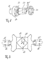
- FIG. 2 shows an adjusting nozzle 20, which is connected to a flange 21 Injection molding device 22 can be screwed on.
- a graduated paragraph 23 on the Adjusting nozzle 20 is used for the precisely fitting insertion of the adjusting nozzle 20 in an oppositely stepped paragraph 24 on the injection molding device 22. After Attaching the adjusting nozzle 20 to the injection molding device 22 is done by this Slip on the flange 21 and screw the flange 21 onto the Injection molding device 22 attached.
- the adjustment nozzle 20 has an inlet on the side of the injection molding device 22 and two outputs 20 'on the tool side. Opposed check valves 25, 26 and 25 ', 26' are provided.
- FIG. 3 shows one possibility of using such an adjustment nozzle. This allows the molded part 27 either in the direction of arrow 28 or in To flow in the direction of arrow 29. In this way, without Realize different layers. It is understood that other flow paths can also be controlled by such a nozzle 20 can.
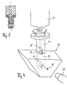
- the hot runner block 30 shown in FIG. 4 works with a special one Adjusting nozzle 31 together.
- the heating channel block has a continuous channel 32 and a central round opening 33 intersecting the channel 32 into which the Nozzle head of the adjusting nozzle 31 can be inserted.
- This nozzle head has a cross to the adjusting nozzle axis extending bore 34 which in diameter Channel 32 corresponds and by sinking the adjusting nozzle into the opening 33 of the Hot runner blocks 30 are aligned with the channel 32.
- an L-shaped bore 35 in the adjustment nozzle 31 provided, which is also to be aligned with the channel 32 and then connects the adjustment nozzle body 36 to the channel 32 to plasticize Material from adjusting nozzle body 36 through the L-shaped channel 35 in the Promote channel 32.
- the channel 32 finally has a feed 37 with the mold cavity 3 in Connection.
- the adjustment nozzle can also be used in another direction, so that the L-shaped channel 35 melt from a secondary extruder to one Main extruder, from which the melt can then convey through the channel 35 back into the channel 32 and into the mold nest 3.
- nozzles 20 and 31 ensure by their compact Set up a particularly simple implementation of the above-described methods. You can easily put on instead of existing catchy nozzles Injection molding devices, such as extruders or injection molding machines, are placed be, so that the latter without great structural measures for an application of the method according to the invention can be converted.
- the adjusting nozzles 20 and 31 thus allow different ones in a simple manner Pass through flow paths only by controlling the injection molding device allow.
Abstract
Description
Die Erfindung betrifft ein Verfahren zum Spritzgießen von Spritzgußteilen aus plastifizierbarem Material, bei dem ein erstes plastifiziertes Material durch eine erste Öffnung in eine Spritzgießform eingespritzt wird und sich am Rand der Form verfestigt und anschließend ein zweites, von dem ersten sich unterscheidendes plastifiziertes Material in die Spritzgießform eingespritzt wird.The invention relates to a method for injection molding of injection molded parts made of plasticizable material, in which a first plasticized material is injected through a first opening into an injection mold and on Edge of the form solidified and then a second, from the first itself distinguishing plasticized material is injected into the injection mold.
Ferner betrifft die Erfindung eine Justierdüse für eine Spritzgußvorrichtung.The invention further relates to an adjusting nozzle for an injection molding device.
Derartige Verfahren werden als Sandwich-Verfahren oder als Mono-Sandwich-Verfahren bezeichnet. Sie führen bei dem Spritzgußteil zu einer äußeren Hülle und einem Kern, wobei vorzugsweise Hülle und Kern aus unterschiedlichen Materialien gefertigt sind. Die Festigkeit derartiger Materialien wird durch die Auswahl der verwendeten Materialien und deren Stärke beeinflußt.Such processes are known as sandwich processes or as mono-sandwich processes designated. They lead to an outer shell in the injection molded part and a core, the shell and core preferably being made of different Materials are made. The strength of such materials is determined by the Selection of the materials used and their strength influenced.
Die EP-A- 0 191 623 beschreibt ein Verfahren zum Spritzgießen von Spritzgußteilen aus plastifizierbarem Material, bei welchem ein erstes plastifizierbares Material in eine Spritzgießform eingespritzt wird und sich am Rand der Form verfestigt, und anschließend ein zweites, sich von dem ersten unterscheidendes plastifiziertes Material in die Spritzgießform eingespritzt wird. Nach dem Einspritzen wird mittels einer periodischen Druckschwankung weiteres plastifiziertes Material eingefügt und so die Packungsdichte erhöht.EP-A-0 191 623 describes a method for injection molding injection molded parts made of plasticizable material, in which a first plasticizable Material is injected into an injection mold and located on the edge the shape solidified, and then a second, different from the first plasticized material is injected into the injection mold. After the injection, a periodic pressure fluctuation causes further plasticized material inserted and thus increases the packing density.
Darüber hinaus ist aus der EP-A-0 424 624 eine gattungsgemäße Anordnung bekannt, nach welcher jeweils zwei Eingänge in einen Hohlraum einer Spritzgießform über gegenläufige Rückschlagventile miteinander verbunden sind. Diese Rückschlagventile sind ebenfalls in der Spritzgießform angeordnet und mit dem Eingang in die Spritzgießform, an welchem dann eine Düse eines Extruders ansetzen kann, verbunden.In addition, a generic arrangement is known from EP-A-0 424 624, according to which each have two entrances into a cavity of an injection mold opposed check valves are interconnected. These check valves are also arranged in the injection mold and with the entrance into the injection mold, on which a nozzle of an extruder then attach can, connected.
Der Erfindung liegt die Aufgabe zugrunde, die Festigkeit der mit dem bekannten Verfahren herstellbaren Spritzgußteile zu erhöhen.The invention has for its object the strength of the known methods to increase producible injection molded parts.
Diese Aufgabe wird dadurch gelöst, daß nur das zweite plastifizierte Material während des Erstarrens derart bewegt wird, daß es durch eine zweite Öffnung überströmt.This object is achieved in that only the second plasticized material is moved during the solidification in such a way that it overflows through a second opening.
Des weiteren wird diese Aufgabe durch die Justierdüse gemäß Patentanspruch
12 und durch die Justierdüse gemäß Patentanspruch 14 gelöst.Furthermore, this object is achieved by the adjusting nozzle according to the
Zweckmäßige Weiterbildugen der Erfindung sind Gegenstand der betreffenden abhängigen Ansprüche.Appropriate further developments of the invention are the subject of the relevant dependent claims.
Das Bewegen des Materials führt einerseits zu einer erhöhten Festigkeit und andererseits zu einer guten Verbindung zwischen erstem und zweitem Material. Hierbei versteht es sich, daß das erste und zweite Material auch bis auf die verwendete Temperatur oder sonstige Parameter identisch gewählt werden können. Durch die Erfindung lassen sich Spritzgußteile mit völlig neuen und neuartigen Eigenschaften herstellen.Moving the material leads on the one hand to increased strength and on the other hand to a good connection between the first and second material. Here it goes without saying that the first and second material also except for the used temperature or other parameters can be chosen identically can. The invention allows injection molded parts with completely new and create new properties.
Vorteilhaft ist es, wenn das zweite plastifizierte Material von mindestens einer zweiten Öffnung in die Spritzgießform eingespritzt wird. Das Einspritzen des Materials von verschiedenen Seiten bringt den Vorteil, daß die zum Einspritzen der Materialien verwendeten Kolben oder Schnecken gegeneinander getaktet werden können, so daß im zweiten plastifizierten Material eine Bewegung entsteht.It is advantageous if the second plasticized material of at least one second opening is injected into the injection mold. The injection of the Material from different sides has the advantage that it can be injected the materials used pistons or screws clocked against each other can be, so that a movement in the second plasticized material arises.
Eine derartige Kolbenanordnung erlaubt es auch, das zweite plastifizierte Material nur in einer Richtung zu bewegen. Eine Bewegung des zweiten plastifizierten Materials in einer Richtung kann jedoch auch mittels eines Kolbens und einer Überströmöffnung in der Spritzgießform erzielt werden. Sofern die Spritzgießform zwei Öffnungen hat, können diese Öffnungen auch über einen Bypaß miteinander verbunden werden, so daß mit einer passenden Ventiltechnik das zweite plastifizierte Material im Kreis bewegt werden kann. Die Bewegung kann einerseits durch die Zuführschnecken oder -kolben erzeugt werden. Andererseits kann jedoch auch im Bypaß eine Pumpe vorgesehen sein.Such a piston arrangement also allows the second plasticized Move material in one direction only. A movement of the second plasticized material in one direction can, however, also by means of a Piston and an overflow opening can be achieved in the injection mold. If the injection mold has two openings, these openings can also be connected to each other via a bypass, so that with a suitable Valve technology the second plasticized material can be moved in a circle. The movement can be generated on the one hand by the feed screws or pistons become. On the other hand, however, a pump can also be provided in the bypass.
Eine bevorzugte Ausführungsform sieht vor, daß die Bewegung durch Oszillation des Einspritzkolbens oder der Einspritzkolben erzeugt wird. Die Oszillation bewirkt keine starke Masseverschiebung und hat jedoch den Vorteil, daß das plastifizierte Material ausgerichtet wird. A preferred embodiment provides that the movement through Oscillation of the injection plunger or the injection plunger is generated. The Oscillation does not cause a strong mass shift, but has the advantage that the plasticized material is aligned.
Eine Variante sieht vor, daß die Bewegung durch Ultraschall erzeugt wird. Auch mit Ultraschall kann in der Spritzgießform eine Bewegung erzeugt werden, die ausschließlich das zweite plastifizierte Material bewegt.A variant provides that the movement is generated by ultrasound. A movement can also be generated in the injection mold using ultrasound which only moves the second plasticized material.
Eine weitere Variante sieht vor, daß ein elektromagnetisches Feld auf das zweite plastifizierte Material einwirkt. Auch dadurch ist eine Ausrichtung des plastifizierten Materials zu erreichen.Another variant provides that an electromagnetic field on the second plasticized material acts. This is also an orientation of the to achieve plasticized material.
Bei speziellen Anwendungsgebieten ist es möglich, die Bewegung durch Eindüsen eines Fluids zu erzeugen. Unter Fluid wird einerseits ein Gas verstanden, andererseits kann das Fluid jedoch auch eine beliebige Flüssigkeit sein, die in das zweite plastifizierte Material eingedüst wird. Hierbei wird das Fluid zum Schieben bzw. Nachschieben des Materials genutzt. Hierbei kann das Fluid dazu genutzt werden, in dem Spritzgußteil einen oder mehrere Hohlräume zu erzeugen. Gleichwohl bleibt es bei diesen Vorgängen vorteilhafterweise passiv, reagiert also mit der Schmelze nur unwesentlich.In special areas of application, it is possible to inject movement to generate a fluid. Fluid is understood on the one hand to be a gas on the other hand, however, the fluid can also be any liquid which is in the second plasticized material is injected. Here the fluid becomes Pushing or pushing the material used. Here, the fluid be used to one or more cavities in the injection molded part produce. Nevertheless, these processes advantageously remain passive, reacts only insignificantly with the melt.
Eine weitere Variante sieht vor, daß die Bewegung durch eine Schmelzepumpe erzeugt wird. Beispielsweise durch eine Zahnradpumpe, die anstelle eines Kolbens eingesetzt wird, kann eine Bewegung in eine Richtung oder eine Hinund Herbewegung erzeugt werden.Another variant provides that the movement by a melt pump is produced. For example, by a gear pump instead of a Piston is used, one-way or one-way motion Movement are generated.
Ein Ausführungsbeispiel der Erfindung sieht vor, daß das zweite plastifizierte Material von zwei Stellen zumindest zum Teil gleichzeitig in die Spritzgießform eingespritzt wird. Das Material trifft dann an einer Stelle aufeinander und es entsteht dort eine Naht, die durch die Bewegung besonders verfestigt werden kann bzw. verfestigt wird. Dieser Nahtbereich führt zu einer besonders hohen Festigkeit und es wird daher vorgeschlagen, diesen Nahtbereich in besonders beanspruchte Bereiche zu legen. Der Nahtbereich, der früher in weniger beanspruchte Bereiche gelegt wurde, da er nur eine geringe Festigkeit aufweist, hat durch die Bewegung des plastifizierten Materials während des Erstarrens eine etwa um den Faktor 4 erhöhte Festigkeit. Dieser Vorteil ist nicht auf das Sandwich-Verfahren beschränkt, sondern kann allgemein bei Spritzgießverfahren genutzt werden.An embodiment of the invention provides that the second plasticized Material from two places at least partially at the same time in the injection mold is injected. The material then meets at one point and it a seam is created there, which is particularly solidified by the movement can or is solidified. This seam area leads to a particularly high one Strength and it is therefore suggested that this seam area in particular to lay stressed areas. The seam area that used to be in less stressed areas because it has little strength, caused by the movement of the plasticized material during solidification strength increased by a factor of around 4. This advantage is not on that Sandwich process limited, but can generally be used in injection molding be used.
Beispielsweise zum Einbringen elektronischer Schaltungen in ein Spritzgußteil wird vorgeschlagen, daß vor oder nach dem Einspritzen des ersten plastifizierten Materials eine Folie oder ein Verstärkungsgewebe in die Spritzgießform eingelegt wird. Die Folie kann eine elektrische Schaltung aufweisen und das Verstärkungsgewebe kann einer Festigkeitserhöhung dienen. Die eingelegte Folie kann aus unterschiedlichen Materialien bestehen. Eine Dekorfolie dient optischen Zwecken. Die Folie kann jedoch auch bestimmte chemische und/oder physikalische und/oder elektrische und/oder thermische und/oder optische und/oder mechanische Eigenschaften haben, die der spezielle Anwendungsfall erfordert. Ein breites Anwendungsgebiet erschließen Folien, die auf fotooptische oder galvanische Weise erzeugte elektrische oder elektronische Schaltungen aufweisen. Als Verstärkungsgewebe kann insbesondere ein Glasfaser-, ein Kohlefaser und/oder ein Eigenfasergewebe dienen, wobei das Eigenfasergewebe Fasern aus einem in dem ersten und/oder zweiten plastifizierten Material enthaltenen Material umfaßt. Die Verwendung derartiger Verstärkungsgewebe bzw. Folien ist auch für sich genommen vorteilhaft, um einerseits gewünschte Eigenschaften, wie Dekor, Festigkeit oder Leitfähigkeit, und anderseits die beim Spritzgießen erreichbaren hohen Fertigungsraten zu ermöglichen.For example, for introducing electronic circuits into an injection molded part it is proposed that before or after the injection of the first plasticized material into a film or a reinforcing fabric Injection mold is inserted. The foil can be an electrical circuit have and the reinforcing fabric can serve to increase strength. The inserted film can consist of different materials. A Decorative film is used for optical purposes. However, the film can also be certain chemical and / or physical and / or electrical and / or thermal and / or have optical and / or mechanical properties that the special Use case requires. Films have a wide range of applications, the electrical or generated in a photo-optical or galvanic manner have electronic circuits. Can be used as reinforcing fabric in particular a glass fiber, a carbon fiber and / or an own fiber fabric serve, the self-fiber fabric fibers from one in the first and / or includes second plasticized material. The usage such reinforcing fabric or films is also taken on its own advantageous to achieve desired properties, such as decor, strength or Conductivity, and on the other hand the high achievable during injection molding Allow manufacturing rates.
Hierbei kann insbesondere das Eigenfasergewebe bereits gerichtet eingebracht werden. Darüber hinaus kann das Verfahren derart betrieben werden, daß zunächst flüssige Schmelze eingebracht wird, die das Gewebe durchdringt. Anschließend wird das zweite Material, beispielsweise eine mit Eigenfasern durchsetzte Schmelze, eingebracht und nach Bedarf in erfindungsgemäßer Weise bewegt. Hierdurch kann eine Naht in gewünschter Weise verstärkt werden.In this case, the self-fiber fabric in particular can already be introduced in a directed manner become. In addition, the method can be operated in such a way that liquid melt is first introduced, which penetrates the tissue. Then the second material, for example one with its own fibers permeated melt, introduced and as required in the inventive manner emotional. In this way, a seam can be reinforced in the desired manner.
Die vorbeschriebene Anwendung kann auch zusammen mit dem vorbeschriebenen Einsatz eines Fluids Verwendung finden.The application described above can also be used together with the application described above Use a fluid.
Eine in vielen Fällen vorteilhafte Variante des Verfahrens sieht vor, daß das erste Material nur einen Teil der Wandung der Spritzgießform bedeckt. Dies führt dazu, daß das Spritzgußteil eine Außenwandung aus zwei verschiedenen Materialien hat, die beispielsweise in unterschiedlichen Farben ausgeführt sein können. Bei diesem Verfahren wird vorzugsweise ein Absatz in der Form genutzt, um einen definierten Übergang zwischen den beiden Materialien zu erzielen.A variant of the method which is advantageous in many cases provides that the first material covered only part of the wall of the injection mold. This causes the injection molded part to have an outer wall made of two different ones Has materials, for example, in different colors can. In this method, a paragraph is preferably in the form used to create a defined transition between the two materials achieve.
Eine Alternative dazu sieht vor, daß nach teilweisem Befüllen der Spritzgießform mit einem ersten Material mittels eines Schiebers ein weiterer Bereich der Spritzgießform geöffnet wird, der anschließend mit dem zweiten Material gefüllt wird. Auch der Schieber führt zu einem definierten Übergang vom ersten zum zweiten Material. Vorzugsweise wird in Abhängigkeit vom Einspritzvorgang - d.h. beispielsweise von der Wegstrecke, die eine Zuführschnecke zurückgelegt hat, von der für den Spritzvorgang durchlaufenden Zeit bzw. von einem an der Einspritzvorrichtung oder im Werkzeug ermittelten Druck - der Schieber aktiviert.An alternative to this is that after partial filling of the Injection mold with a first material by means of a slide another Area of the injection mold is opened, which then with the second Material is filled. The slider also leads to a defined transition from the first to the second material. Preferably, depending on Injection process - i.e. for example from the distance that one Feed screw has traveled from the one running through for the spraying process Time or from one determined on the injection device or in the tool Pressure - the slide is activated.
Eine Modifikation des erfindungsgemäßen Verfahrens sieht vor, daß vor dem ersten plastifizierbaren Material mindestens ein weiteres plastifizierbares Material eingespritzt wird. Dies führt zu einem Aufbau des Spritzgußteils aus einzelnen konzentrischen Schichten, wobei je nach Verfahrensführung das plastifizierte Material bestimmter Schichten bewegt werden kann. Bewegte und unbewegte Schichten können abgewechselt werden und es können nacheinander bewegte Schichten baumkuchenartig eingebracht werden, um ein besonders festes Spritzgußteil zu erzeugen.A modification of the method according to the invention provides that before first plasticizable material at least one other plasticizable Material is injected. This leads to a structure of the injection molded part individual concentric layers, depending on the procedure plasticized material of certain layers can be moved. Moved and unmoving shifts can be alternated and one after the other moving layers like a Baumkuchen are introduced to make a special to produce a solid injection molded part.
Vorteilhaft ist es, wenn das zweite plastifizierte Material einen Füllstoff aufweist. Als Füllstoff sind Fasern, Partikel, Ruß und Metalle möglich. Als plastifiziertes Material kommt neben Kunststoffen auch plastifizierbare Keramik und plastifizierbares Pulvermetall in Frage.It is advantageous if the second plasticized material contains a filler having. Fibers, particles, soot and metals are possible as fillers. As In addition to plastics, plasticized material also comes with plasticizable ceramics and plasticizable powder metal in question.
Die nach den beschriebenen Verfahren hergestellten Spritzgußteile eignen sich wegen ihrer hohen Festigkeit als Stabilisator, als Strebe- oder Gelenkwelle und als Verstärkungshülse (Insert) für unterschiedlichste Zwecke. Die Teile sind sowohl besonders auf Zugdruck als auch auf Biegung gut beanspruchbar. Die Verwendung unterschiedlicher Materialien, insbesondere als erstes plastifiziertes Material, erschließt die Herstellung von Deckeln oder Gehäusen mit Dichtung, Laufrollen mit Nabe und Lauffläche, Schwingungsabsorberfüßen, Stoßdämpfern, Kühlwasserrohren mit harten und weichen Bereichen, Filterelemente, Kupplungspedale oder sonstige Pedalen.The injection molded parts produced by the processes described are suitable because of their high strength as a stabilizer, as a strut or cardan shaft and as a reinforcement sleeve (insert) for various purposes. The parts are Can be used particularly well under tension as well as bending. The Use of different materials, especially the first plasticized Material, opens up the manufacture of covers or housings with seals, Castors with hub and tread, vibration absorber feet, shock absorbers, Cooling water pipes with hard and soft areas, filter elements, Clutch pedals or other pedals.
Gerade die Verwendung von thermoplastischem Gummi als plastifizierbares Material ermöglicht auch die Herstellung von Scharnieren, wobei zwei oder mehrere feste Kunststoffmaterialien durch ein Gummistück miteinander verbundien sind. Bei einem bevorzugten Ausführungsbeispiel werden von zwei Seiten als erstes plastifiziertes Material härtere, thermoplastische Kunststoffe eingespritzt, die zwei beabstandete Körper bilden. Anschließend wird der Abstand zwischen den Körpern und ggf. eine Innenseite mit Gummimaterial ausgefüllt, so daß ein Scharnier zwischen zwei Kunststoffteilen entsteht.Especially the use of thermoplastic rubber as plasticizable Material also allows the production of hinges, two or several solid plastic materials are connected by a rubber piece are. In a preferred embodiment, two Sides as the first plasticized material harder, thermoplastic injected, which form two spaced bodies. Then the Distance between the bodies and, if necessary, an inside with rubber material filled in so that a hinge is created between two plastic parts.
Bezüglich der Justierdüse hat sich in der Praxis herausgestellt, daß die Positionierung der Justierdüse zwischen Spritzgießform und Spritzgußvorrichtung häufig sehr zeitaufwendig ist.With regard to the adjusting nozzle, it has been found in practice that the positioning of the adjusting nozzle between injection mold and injection molding device often very time consuming is.
Üblicherweise ist die Justierdüse in die Fläche an der Spritzgußvorrichtung eingeschraubt und beim Einschrauben der Justierdüse verändert sich der Abstand des Düsenendes zur Spritzgußvorrichtung. Dieses Problem wird dadurch eleminiert, daß ein an der Justierdüse befestigter Flansch oder ein über die Justierdüse stülpbarer Flansch mit der Spritzgußvorrichtung fest verbunden ist, so daß die Justierdüse in einer beliebigen um ihre Achse gedrehten Position an der Spritzgußvorrichtung befestigbar ist. Insbesondere wenn die Justierdüse mehrere Öffnungen hat, die abwechselnd genutzt werden sollen, ist die beschriebene Vorrichtung von besonderem Vorteil.The adjustment nozzle is usually in the surface of the injection molding device screwed in and when screwing in the adjusting nozzle, the changes Distance from the nozzle end to the injection molding device. This problem will thereby eliminated that a flange attached to the adjusting nozzle or an over the adjustable nozzle pluggable flange firmly connected to the injection molding device is so that the adjusting nozzle in any position rotated about its axis is attachable to the injection molding device. Especially when the adjustment nozzle has several openings that are to be used alternately is the described device of particular advantage.
Des weiteren ist vorgesehen, daß die Justierdüse verschiedene Kanäle aufweist und in einem Block beweglich ist, so daß ein Kanal der Justierdüse mit einem Kanal im Block fluchtet.Furthermore, it is provided that the Adjusting nozzle has different channels and is movable in a block, so that a channel of the adjustment nozzle is aligned with a channel in the block.
Ein Heißkanalblock erlaubt es, entweder von der Justierdüse plastifiziertes Material durch den Heißkanalblock zur Spritzgießform oder zu einem Extruder zu leiten oder die Zuleitung an einer Wandung des Blocks enden zu lassen und durch einen weiteren Kanal der Justierdüse eine Durchströmung des Blocks von diesem Extruder aus zu ermöglichen. Ebenso können verschiedene Extruder auf diese Weise auf eine Einspritzöffnung der Spritzgießform geschaltet werden.A hot runner block allows either from the adjustment nozzle plasticized material through the hot runner block to the injection mold or to an extruder or the feed on a wall of the block to end and through another channel of the adjustment nozzle To allow flow through the block from this extruder. As well can use different extruders in this way to an injection port Injection mold can be switched.
Vorzugsweilse wird die Spritzgußform mit einer niedrig schmelzenden Metallegierung temperiert.The injection mold with a low melting point is preferred Metal alloy tempered.
Eine Justierdüse für eine Spritzgußvorrichtung weist zwei miteinander verbundenen Ausgängen auf, die jeweils mit einem Rückschlagventil versehen sind, wobei die Rückschlagventile gegenläufig angeordnet sind. Es sind aber auch Düsen mit mehreren Kanälen denkbar, wobei in diesem Fall wenigstens eine der Düsen ein Ventil, vorzugsweise ein Rückschlagventil, aufweisen soll. Im übrigen können die Rückschlagventile geeignet gewählt werden.An adjustment nozzle for an injection molding device has two interconnected outputs, each with a check valve are provided, the check valves in opposite directions are arranged. However, nozzles with several channels are also conceivable, in which case at least one of the nozzles is a valve, preferably a Check valve, should have. Otherwise, the check valves be chosen appropriately.
Durch eine niedrig schmelzende Metallegierung kann eine schnelle Werkzeugtemperierung (dynamisch) erreicht werden. Insbesondere eignet sich die Verwendung einer derartigen Metalllegierung für dünnwandige Bereiche, so daß sich hierdurch verhältnismäßig komplexe Spritzgußteile in sehr guter Qualität herstellen lassen. Die Verwendung einer niedrig schmelzenden Metalllegierung ist auch unabhängig von den übrigen vorgenannten Merkmalen zur Temperierung einer Spritzgußform vorteilhaft.Thanks to a low-melting metal alloy, rapid mold tempering can be achieved can be achieved (dynamically). In particular, the use of a such metal alloy for thin-walled areas, so that this relatively complex injection molded parts in very good quality. The use of a low melting metal alloy is also regardless of the other aforementioned characteristics for tempering a Injection mold advantageous.
Eine Vorrichtung zur Durchführung des erfindungsgemäßen Verfahrens sowie eine Justierdüse sind als Ausführungsbeispiel in der Zeichnung dargestellt und werden im folgenden näher erläutert.A device for carrying out the method according to the invention and an adjusting nozzle are as Embodiment shown in the drawing and are described in more detail below explained.
Es zeigt,
Figur 1- eine schematische Darstellung einer Spritzgießvorrichtung für das erfindungsgemäße Verfahren,
- Figur 2
- die Befestigung einer Justierdüse an einer Spritzgußvorrichtung und
Figur 3- eine schematische Darstellung zur Durchströmung einer Spritzgießform,
- Figur 4
- eine perspektivische Ansicht eines Heißkanalblocks mit Justierdüse und
- Figur 5
- einen Schnitt durch die Justierdüse nach Figur 4.
- Figure 1
- 1 shows a schematic illustration of an injection molding device for the method according to the invention,
- Figure 2
- the attachment of an adjusting nozzle to an injection molding device and
- Figure 3
- 1 shows a schematic illustration of the flow through an injection mold,
- Figure 4
- a perspective view of a hot runner block with adjusting nozzle and
- Figure 5
- a section through the adjusting nozzle according to Figure 4.
Die in Figur 1 dargestellte Spritzgießvorrichtung 1 besteht aus einer
Spritzgießform 2 mit einem Formnest 3, das zwei Öffnungen 4 und 5 aufweist.
Diese Öffnungen 4 und 5 sind über sich verzweigende Leitungen 6 und 7
jeweils mit zwei Zuführvorrichtungen 8, 9 und 10, 11 für plastifiziertes
Material verbunden. Die sich verzweigenden T-Stücke 14, 15 erlauben es
abwechselnd, jeweils nur eine der Zuführvorrichtungen 8 oder 9 bzw. 10 oder
11 mit dem Formnest 3 zu verbinden.The
Dadurch ist es möglich, zunächst von zwei Seiten plastifiziertes Material in das
Formnest 3 aus den Zuführaggregaten 8 und 11 zuzuführen und anschließend
ein anderes plastifiziertes Material durch die Zuführvorrichtungen 9 und 10 in
das Formnest 3 zu leiten.This makes it possible to first plasticize the material from two sides into the
Außerdem kann zunächst aus den Zuführvorrichtungen 9 und 10 plastifiziertes
Material in die Zuführvorrichtungen 8 und 11 gedrückt werden und
anschließend wird zunächst aus einer der Zuführvorrichtungen 8 geschichtetes
Material in das Formnest geschoben und dann aus der anderen Vorrichtung 11
geschichtetes Material in das Formnest geschoben. Dadurch entsteht eine
vierfache Schichtung im Formnest. In addition, plasticized material can first be made from the
Darüber hinaus kann das in das Formnest 3 durch eine Öffnung 4 eingeführte
Material überströmen und durch die weitere Öffnung 5 in ein anderes
Zuführaggregat überströmen oder es kann in einen Bypass 12 geschoben
werden. Darüber hinaus erlaubt die Pumpe 13 im Bypass 12 eine
Kreislaufströmung durch das Formnest 3.In addition, the inserted into the
Je nach Ventilstellung an den Stellen 14 und 15 können somit die eingangs beschriebenen Verfahren realisiert werden.Depending on the valve position at points 14 and 15, the input described methods can be realized.
Die Figur 2 zeigt eine Justierdüse 20, die mit einem Flansch 21 an eine
Spritzgußvorrichtung 22 anschraubbar ist. Ein gestufter Absatz 23 an der
Justierdüse 20 dient dabei dem passgenauen Einsetzen der Justierdüse 20 in
einen entgegengesetzt gestuften Absatz 24 an der Spritzgußvorrichtung 22. Nach
Ansetzen der Justierdüse 20 an der Spritzgußvorrichtung 22 wird diese durch
Überstülpen des Flansches 21 und Anschrauben des Flansches 21 an der
Spritzgußvorrichtung 22 befestigt.FIG. 2 shows an adjusting
Die Justierdüse 20 weist einen Eingang an der Seite der Spritzgußvorrichtung
22 sowie zwei Ausgänge 20' an der Werkzeugseite auf.
Innerhalb der Justierdüse 20 sind gegenläufige Rückschlagventile 25, 26 bzw.
25', 26' vorgesehen.The
Die Figur 3 zeigt eine Möglichkeit des Einsatzes einer derartigen Justierdüse.
Dies erlaubt es, das Formteil 27 entweder in Richtung des Pfeiles 28 oder in
Richtung des Pfeiles 29 zu durchströmen. Auf diese Weise lassen sich ohne
Weiteres verschieden gerichtete Schichtungen realisieren. Es versteht sich, daß
auch andere Strömungswege durch eine derartige Düse 20 angesteuert werden
können.FIG. 3 shows one possibility of using such an adjustment nozzle.
This allows the molded
Der in Figur 4 gezeigte Heißkanalblock 30 arbeitet mit einer speziellen
Justierdüse 31 zusammen. Der Heizkanalblock hat einen durchgehenden Kanal
32 und eine den Kanal 32 schneidende zentrale runde Öffnung 33, in den der
Düsenkopf der Justierdüse 31 einschiebbar ist. Dieser Düsenkopf hat eine quer
zur Justierdüsenachse sich erstreckende Bohrung 34, die im Durchmesser dem
Kanal 32 entspricht und durch Einsenken der Justierdüse in die Öfffnung 33 des
Heißkanalblocks 30 mit dem Kanal 32 fluchtet.The
Oberhalb der Bohrung 34 ist in der Justierdüse 31 eine L-förmige Bohrung 35
vorgesehen, die ebenfalls mit dem Kanal 32 zum Fluchten zu bringen ist und
dann den Justierdüsenkörper 36 mit dem Kanal 32 verbindet, um plastifiziertes
Material von Justierdüsenkörper 36 durch den L-förmigen Kanal 35 in den
Kanal 32 zu fördern.Above the
Der Kanal 32 steht schließlich mit einer Zuführung 37 mit dem Formnest 3 in
Verbindung.The
Andererseits kann die Justierdüse auch in anderer Richtung verwendet werden,
so daß der L-förmige Kanal 35 Schmelze von einem Nebenextruder zu einem
Hauptextruder fördern kann, von welchem die Schmelze dann, durch den Kanal
35 zurück, in den Kanal 32 und in das Formnest 3 befördert wird. On the other hand, the adjustment nozzle can also be used in another direction,
so that the L-shaped
Die vorbeschriebenen Düsen 20 und 31 gewährleisten durch ihren kompakten
Aufbau eine besonders einfache Umsetzung der vorbeschriebenen Verfahren.
Sie können ohne Weiteres anstelle bestehender eingängiger Düsen auf
Spritzgußvorrichtungen, wie Extruder bzw. Spritzkolbenmaschinen, aufgesetzt
werden, so daß letztere ohne große bauliche Maßnahmen für eine Anwendung
des erfindungsgemäßen Verfahrens umgerüstet werden können.The above-described
Die Justierdüsen 20 und 31 erlauben somit auf einfache Weise verschiedene
Strömungswege lediglich durch Steuerung der Spritzgußvorrichtung durchlaufen
zu lassen.The adjusting
Claims (17)
- A method for injection moulding injection moulded parts from material that can be plasticized, wherein a first plasticized material is injected into an injection mould (2) through a first opening (4, 5) and solidifies on the edge of the mould, and wherein a second plasticized material that differs from the first plasticized material is subsequently injected into the injection mould (2), characterized by the fact that only the second plasticized material is moved during the solidification process in such a way that it overflows through a second opening (5, 4).
- The method according to Claim 1, characterized by the fact that the second plasticized material is only moved in one direction.
- The method according to one of the preceding claims, characterized by the fact that the movement is generated by means of ultrasound.
- The method according to one of the preceding claims, characterized by the fact that an electromagnetic field acts upon the second plasticized material.
- The method according to one of the preceding claims, characterized by the fact that the movement is generated by a pump (13) for the molten mass.
- The method according to one of the preceding claims, characterized by the fact that the second plasticized material is at least partially injected into the injection mould (2) simultaneously from two points (4, 5).
- The method according to one of the preceding claims, characterized by the fact that a film or a reinforcing fabric is placed into the injection mould (2) before or after injecting the plasticized material.
- The method according to one of the preceding claims, characterized by the fact that the first material only covers part of the wall of the injection mould (2).
- The method according to one of the preceding claims, characterized by the fact that, after partially filling the injection mould (2) with the first material, a slide opens another region of the injection mould which is subsequently filled with the second material.
- The method according to one of the preceding claims, characterized by the fact that at least one other material that can be plasticized is injected before the first plasticized material.
- The method according to one of the preceding claims, characterized by the fact that the injection mould (2) is tempered with a metal alloy that has a low melting point.
- An adjusting nozzle for an injection moulding device, characterized by two outlets (20') that are connected to one another and respectively provided with a return valve (25, 25'; 26, 26'), wherein the return valves (25, 25'; 26, 26') are arranged such that they act in opposite directions.
- The adjusting nozzle for an injection moulding device according to Claim 12, characterized by the fact that the adjusting nozzle (20) adjoins a surface (24) and is mounted by means of a flange (21).
- An adjusting nozzle for an injection moulding device, characterized by the fact that the adjusting nozzle (31) contains different channels (34, 35) and is movably guided in a block (30) in such a way that one channel (34, 35) of the adjusting nozzle (31) is aligned with a channel (32) in the block (30).
- The adjusting nozzle according to Claim 14, characterized by the fact that the adjusting nozzle (31) contains a L-shaped channel (35) that is connected to a secondary extruder.
- The adjusting nozzle according to Claim 14 or 15, characterized by the fact that the channel (32) in the block (30) is connected to a primary extruder.
- The adjusting nozzle according to one of Claims 14 - 16, characterized by the fact that the channel (32) in the block (30) is connected to a mould cavity (3).
Applications Claiming Priority (7)
| Application Number | Priority Date | Filing Date | Title |
|---|---|---|---|
| DE19736371 | 1997-08-21 | ||
| DE19736371 | 1997-08-21 | ||
| DE19808145A DE19808145A1 (en) | 1997-08-21 | 1998-02-27 | Injection moulding of articles with two components |
| DE19808145 | 1998-02-27 | ||
| US7647298P | 1998-03-02 | 1998-03-02 | |
| US76472 | 1998-03-02 | ||
| PCT/DE1998/002448 WO1999010157A1 (en) | 1997-08-21 | 1998-08-21 | Method and device for injection moulding plastifiable parts |
Publications (2)
| Publication Number | Publication Date |
|---|---|
| EP1005408A1 EP1005408A1 (en) | 2000-06-07 |
| EP1005408B1 true EP1005408B1 (en) | 2002-07-31 |
Family
ID=27217666
Family Applications (2)
| Application Number | Title | Priority Date | Filing Date |
|---|---|---|---|
| EP98951185A Withdrawn EP1007318A1 (en) | 1997-08-21 | 1998-08-21 | Method for injection moulding, injection mould, injection moulding device and method for filling a main extruder from a secondary extruder |
| EP98949928A Expired - Lifetime EP1005408B1 (en) | 1997-08-21 | 1998-08-21 | Method and adjustable nozzle for injection moulding plastifiable parts |
Family Applications Before (1)
| Application Number | Title | Priority Date | Filing Date |
|---|---|---|---|
| EP98951185A Withdrawn EP1007318A1 (en) | 1997-08-21 | 1998-08-21 | Method for injection moulding, injection mould, injection moulding device and method for filling a main extruder from a secondary extruder |
Country Status (2)
| Country | Link |
|---|---|
| EP (2) | EP1007318A1 (en) |
| WO (2) | WO1999010157A1 (en) |
Cited By (2)
| Publication number | Priority date | Publication date | Assignee | Title |
|---|---|---|---|---|
| DE102012004168A1 (en) | 2011-03-04 | 2012-09-06 | Heiner Becker | Method for injection molding of continuous fiber reinforced hollow body, involves fixing and positioning pre-consolidated or hardened hybrid braided tubes made of mixed continuous plastic fibers and interwoven glass fibers or carbon fibers |
| DE102016003035A1 (en) | 2015-03-09 | 2016-09-15 | Heiner Becker | Fluid process for impregnating textiles and coating preforms |
Families Citing this family (5)
| Publication number | Priority date | Publication date | Assignee | Title |
|---|---|---|---|---|
| DE10307616A1 (en) * | 2003-02-22 | 2004-09-02 | Merck Patent Gmbh | Injection unit for processing meltable materials |
| DE102008021021A1 (en) * | 2008-04-25 | 2009-10-29 | Newfrey Llc, Newark | Method for producing a fastening device and fastening device for elongate object |
| ITMO20090145A1 (en) * | 2009-05-28 | 2010-11-29 | Mecaplast Di Conti Afro E C S A S | METHOD FOR REALIZING OBJECTS EQUIPPED WITH INTERNAL CAVITY |
| DE102012025039B4 (en) * | 2012-12-20 | 2015-02-19 | Zahoransky Formenbau Gmbh | Process for the production of injection molded parts in two-component injection molding technology as well as injection molded part |
| DE102018004355A1 (en) * | 2018-06-01 | 2019-12-05 | Entex Rust & Mitschke Gmbh | Mixing of extrudable plastics with small amounts of other substances |
Family Cites Families (20)
| Publication number | Priority date | Publication date | Assignee | Title |
|---|---|---|---|---|
| GB1370075A (en) * | 1972-04-20 | 1974-10-09 | Ici Ltd | Injection moulding |
| GB1420948A (en) * | 1972-10-26 | 1976-01-14 | Ici Ltd | Injection moulding process |
| DE2704503A1 (en) * | 1977-01-17 | 1978-07-20 | Semperit Gmbh | SEMI-FINISHED ITEM |
| DE2709000A1 (en) * | 1977-03-02 | 1978-09-07 | Schaeffler Ohg Industriewerk | Radial sealing ring - has ring supporting outer collar and inner lip made of plastics material having different modulus of elasticity from ring |
| JPS5692038A (en) * | 1979-12-26 | 1981-07-25 | Toppan Printing Co Ltd | Multilayer injection molding |
| JPS57187228A (en) * | 1981-05-13 | 1982-11-17 | Matsushita Electric Ind Co Ltd | Molding method of indicator panel in one body |
| JPS60109926U (en) * | 1983-12-28 | 1985-07-25 | アロン化成株式会社 | double layer structure |
| JPS61108519A (en) * | 1984-11-02 | 1986-05-27 | Yoshida Kogyo Kk <Ykk> | Molding method of multi-color synthetic resin molded part, molding equipment and molded part thereof |
| GB8503695D0 (en) * | 1985-02-13 | 1985-03-13 | Bp Chem Int Ltd | Sandwich mouldings |
| CH667843A5 (en) * | 1985-08-22 | 1988-11-15 | Bucher Guyer Ag Masch | Monitoring flow etc. in mould system - by fitting mould with electromagnetic waves transmitter and sensor and generating signals based on whether waves are interrupted or not |
| DE3932416A1 (en) * | 1989-09-28 | 1991-04-11 | Kloeckner Ferromatik Desma | METHOD FOR INJECTION MOLDING MULTI-COMPONENT PLASTIC BODIES AND DEVICE FOR CARRYING OUT THE METHOD |
| DE3934115A1 (en) * | 1989-10-12 | 1991-04-18 | Kloeckner Ferromatik Desma | Injection moulding tool, partic. for fluid crystal polymers - where cavity is fed by at least two runners in hot runner block with channels from two machines and including one way valve system |
| JP2557713B2 (en) * | 1989-10-13 | 1996-11-27 | 富士写真フイルム株式会社 | Injection mold |
| DE4124342A1 (en) * | 1991-07-23 | 1993-01-28 | Baensch Klaus Peter | Mould for two=part injection moulding esp. of two different plastics - has parting slide across cavity during injection of first part and withdrawn for moulding of second part |
| JP2798103B2 (en) * | 1991-09-26 | 1998-09-17 | 宇部興産株式会社 | Multilayer parison forming method |
| JPH08412B2 (en) * | 1992-07-07 | 1996-01-10 | 肥田電器株式会社 | Buffered synthetic resin molded article and method for producing the same |
| US5443378A (en) * | 1994-07-11 | 1995-08-22 | Ferromatik Milacron Maschinenbau Gmbh | Apparatus for the sandwich method of injection molding |
| GB2299779A (en) * | 1995-04-11 | 1996-10-16 | Brunel University Of West Lond | Injection moulding of thermoplastic resin |
| DE29508151U1 (en) * | 1995-05-17 | 1995-08-17 | Georg Menshen Gmbh & Co Kg | Slit valve for closing containers |
| EP0764510A3 (en) * | 1995-09-22 | 1998-05-27 | ICP Systems, Inc. | Gas assist injection molding method and apparatus |
-
1998
- 1998-08-21 EP EP98951185A patent/EP1007318A1/en not_active Withdrawn
- 1998-08-21 WO PCT/DE1998/002448 patent/WO1999010157A1/en active IP Right Grant
- 1998-08-21 EP EP98949928A patent/EP1005408B1/en not_active Expired - Lifetime
- 1998-08-21 WO PCT/DE1998/002449 patent/WO1999010158A1/en not_active Application Discontinuation
Cited By (2)
| Publication number | Priority date | Publication date | Assignee | Title |
|---|---|---|---|---|
| DE102012004168A1 (en) | 2011-03-04 | 2012-09-06 | Heiner Becker | Method for injection molding of continuous fiber reinforced hollow body, involves fixing and positioning pre-consolidated or hardened hybrid braided tubes made of mixed continuous plastic fibers and interwoven glass fibers or carbon fibers |
| DE102016003035A1 (en) | 2015-03-09 | 2016-09-15 | Heiner Becker | Fluid process for impregnating textiles and coating preforms |
Also Published As
| Publication number | Publication date |
|---|---|
| WO1999010157A1 (en) | 1999-03-04 |
| EP1007318A1 (en) | 2000-06-14 |
| WO1999010158A1 (en) | 1999-03-04 |
| EP1005408A1 (en) | 2000-06-07 |
Similar Documents
| Publication | Publication Date | Title |
|---|---|---|
| DE2445786B2 (en) | Device for the production of an injection molded part | |
| WO2006045720A1 (en) | Method and device for producing proliferated, at least sectionally elongate elements | |
| WO1998023431A1 (en) | Method and device for producing a multilayer plastic element | |
| WO2015011289A1 (en) | Method for producing plastic components, which have a high mechanical load-bearing capacity, with a correct final contour | |
| WO2015181296A1 (en) | Device and method for fibre injection moulding of injection moulded parts | |
| DE4120133A1 (en) | Structural component for use in fibre-reinforced plastic - is partially enclosed by compatible injection moulded plastic e.g. polyolefin, polyurethane, etc. | |
| EP2377665A1 (en) | Device and method for injection moulding a moulded part comprising at least one cavity | |
| DE102006000657B4 (en) | Method and device for producing a plastic molding partly laminated with a covering material and the plastic molding itself | |
| DE102014011135B4 (en) | Method and device for producing a decorative part | |
| EP1005408B1 (en) | Method and adjustable nozzle for injection moulding plastifiable parts | |
| DE10306780A1 (en) | Method and device for foam injection molding | |
| DE19613134A1 (en) | Hollow plastic product manufacture and process plant | |
| DE102008060080B4 (en) | Two-color molding method | |
| EP0295529B1 (en) | Apparatus and method for producing plastic composite articles | |
| DE102018215660A1 (en) | Injection molding tool for the production of injection molded components, and method for the production of injection molded components | |
| DE19819833A1 (en) | Method and device for injecting plastic material | |
| DE102006024307A1 (en) | Injection molding machine comprises plasticizer screw, injection unit and mold with molding cavity, injection unit piston forming part of cavity wall and having microstructured face | |
| EP2910357A1 (en) | Method for producing a composite part | |
| DE19808145A1 (en) | Injection moulding of articles with two components | |
| EP1208955B1 (en) | Injection moulding with variable cavity for making corks | |
| DE19703291C1 (en) | Multi-component pressure injection moulding e.g. of strong lightweight hollow object with tough core and thin outer coating | |
| DE69628164T2 (en) | Process for the production of injection molded articles, apparatus for carrying out this process and new molded articles | |
| DE4235776C2 (en) | Mold for producing plastic parts and method for producing such a mold | |
| WO2018172141A1 (en) | Method and device for producing a part from thermoplastic material and a part produced in accordance with said method | |
| DE19735031A1 (en) | Recombination injection moulding of thermo-, duro- or elastomeric plastic |
Legal Events
| Date | Code | Title | Description |
|---|---|---|---|
| PUAI | Public reference made under article 153(3) epc to a published international application that has entered the european phase |
Free format text: ORIGINAL CODE: 0009012 |
|
| 17P | Request for examination filed |
Effective date: 20000315 |
|
| AK | Designated contracting states |
Kind code of ref document: A1 Designated state(s): CH DE FR GB LI NL |
|
| RBV | Designated contracting states (corrected) |
Designated state(s): CH DE FR GB LI NL |
|
| 17Q | First examination report despatched |
Effective date: 20001130 |
|
| GRAG | Despatch of communication of intention to grant |
Free format text: ORIGINAL CODE: EPIDOS AGRA |
|
| RTI1 | Title (correction) |
Free format text: METHOD AND ADJUSTABLE NOZZLE FOR INJECTION MOULDING PLASTIFIABLE PARTS |
|
| GRAG | Despatch of communication of intention to grant |
Free format text: ORIGINAL CODE: EPIDOS AGRA |
|
| GRAH | Despatch of communication of intention to grant a patent |
Free format text: ORIGINAL CODE: EPIDOS IGRA |
|
| GRAH | Despatch of communication of intention to grant a patent |
Free format text: ORIGINAL CODE: EPIDOS IGRA |
|
| GRAA | (expected) grant |
Free format text: ORIGINAL CODE: 0009210 |
|
| AK | Designated contracting states |
Kind code of ref document: B1 Designated state(s): CH DE FR GB LI NL |
|
| PG25 | Lapsed in a contracting state [announced via postgrant information from national office to epo] |
Ref country code: NL Free format text: LAPSE BECAUSE OF FAILURE TO SUBMIT A TRANSLATION OF THE DESCRIPTION OR TO PAY THE FEE WITHIN THE PRESCRIBED TIME-LIMIT Effective date: 20020731 |
|
| REG | Reference to a national code |
Ref country code: GB Ref legal event code: FG4D Free format text: NOT ENGLISH Ref country code: CH Ref legal event code: EP |
|
| PG25 | Lapsed in a contracting state [announced via postgrant information from national office to epo] |
Ref country code: LI Free format text: LAPSE BECAUSE OF NON-PAYMENT OF DUE FEES Effective date: 20020831 Ref country code: CH Free format text: LAPSE BECAUSE OF NON-PAYMENT OF DUE FEES Effective date: 20020831 |
|
| REF | Corresponds to: |
Ref document number: 59805022 Country of ref document: DE Date of ref document: 20020905 |
|
| GBT | Gb: translation of ep patent filed (gb section 77(6)(a)/1977) |
Effective date: 20020919 |
|
| REG | Reference to a national code |
Ref country code: CH Ref legal event code: PK |
|
| ET | Fr: translation filed | ||
| NLV1 | Nl: lapsed or annulled due to failure to fulfill the requirements of art. 29p and 29m of the patents act | ||
| REG | Reference to a national code |
Ref country code: CH Ref legal event code: PL |
|
| PLBE | No opposition filed within time limit |
Free format text: ORIGINAL CODE: 0009261 |
|
| STAA | Information on the status of an ep patent application or granted ep patent |
Free format text: STATUS: NO OPPOSITION FILED WITHIN TIME LIMIT |
|
| 26N | No opposition filed |
Effective date: 20030506 |
|
| GBPC | Gb: european patent ceased through non-payment of renewal fee |
Effective date: 20090821 |
|
| REG | Reference to a national code |
Ref country code: FR Ref legal event code: ST Effective date: 20100430 |
|
| REG | Reference to a national code |
Ref country code: GB Ref legal event code: S28 Free format text: APPLICATION FILED |
|
| REG | Reference to a national code |
Ref country code: FR Ref legal event code: RN |
|
| PG25 | Lapsed in a contracting state [announced via postgrant information from national office to epo] |
Ref country code: FR Free format text: LAPSE BECAUSE OF NON-PAYMENT OF DUE FEES Effective date: 20090831 |
|
| REG | Reference to a national code |
Ref country code: GB Ref legal event code: S28 Free format text: RESTORATION ALLOWED Effective date: 20100720 |
|
| REG | Reference to a national code |
Ref country code: FR Ref legal event code: FC |
|
| PG25 | Lapsed in a contracting state [announced via postgrant information from national office to epo] |
Ref country code: GB Free format text: LAPSE BECAUSE OF NON-PAYMENT OF DUE FEES Effective date: 20090821 |
|
| REG | Reference to a national code |
Ref country code: DE Ref legal event code: R082 Ref document number: 59805022 Country of ref document: DE Representative=s name: LIERMANN-CASTELL, DE |
|
| REG | Reference to a national code |
Ref country code: DE Ref legal event code: R082 Ref document number: 59805022 Country of ref document: DE Representative=s name: PATENTANWALTSKANZLEI LIERMANN-CASTELL, DE Effective date: 20111220 Ref country code: DE Ref legal event code: R081 Ref document number: 59805022 Country of ref document: DE Owner name: TECHNISCHE UNIVERSITAET CHEMNITZ, DE Free format text: FORMER OWNER: STRUCTOFORM SPRITZGIESSEN ANISOTROPER STRUKTURKOMPONENTEN GMBH, 52070 AACHEN, DE Effective date: 20111220 |
|
| REG | Reference to a national code |
Ref country code: FR Ref legal event code: TP Owner name: HEINER BECKER, DE Effective date: 20130418 |
|
| REG | Reference to a national code |
Ref country code: GB Ref legal event code: 732E Free format text: REGISTERED BETWEEN 20130516 AND 20130522 |
|
| REG | Reference to a national code |
Ref country code: DE Ref legal event code: R082 Ref document number: 59805022 Country of ref document: DE Representative=s name: PATENTANWALTSKANZLEI LIERMANN-CASTELL, DE Effective date: 20131114 Ref country code: DE Ref legal event code: R081 Ref document number: 59805022 Country of ref document: DE Owner name: TECHNISCHE UNIVERSITAET CHEMNITZ, DE Free format text: FORMER OWNER: BECKER, HEINER, 52477 ALSDORF, DE Effective date: 20131114 |
|
| REG | Reference to a national code |
Ref country code: GB Ref legal event code: 732E Free format text: REGISTERED BETWEEN 20140130 AND 20140205 |
|
| REG | Reference to a national code |
Ref country code: DE Ref legal event code: R084 Ref document number: 59805022 Country of ref document: DE Effective date: 20140530 |
|
| REG | Reference to a national code |
Ref country code: FR Ref legal event code: TP Owner name: TECHNISCHE UNIVERSITAT CHEMNITZ, DE Effective date: 20140613 |
|
| REG | Reference to a national code |
Ref country code: GB Ref legal event code: 746 Effective date: 20141223 |
|
| REG | Reference to a national code |
Ref country code: FR Ref legal event code: PLFP Year of fee payment: 19 |
|
| REG | Reference to a national code |
Ref country code: FR Ref legal event code: PLFP Year of fee payment: 20 |
|
| PGFP | Annual fee paid to national office [announced via postgrant information from national office to epo] |
Ref country code: GB Payment date: 20170830 Year of fee payment: 20 Ref country code: FR Payment date: 20170830 Year of fee payment: 20 |
|
| REG | Reference to a national code |
Ref country code: DE Ref legal event code: R082 Ref document number: 59805022 Country of ref document: DE Representative=s name: PATENTANWALTSKANZLEI LIERMANN-CASTELL, DE |
|
| PGFP | Annual fee paid to national office [announced via postgrant information from national office to epo] |
Ref country code: DE Payment date: 20171020 Year of fee payment: 20 |
|
| REG | Reference to a national code |
Ref country code: DE Ref legal event code: R071 Ref document number: 59805022 Country of ref document: DE |
|
| REG | Reference to a national code |
Ref country code: GB Ref legal event code: PE20 Expiry date: 20180820 |
|
| PG25 | Lapsed in a contracting state [announced via postgrant information from national office to epo] |
Ref country code: GB Free format text: LAPSE BECAUSE OF EXPIRATION OF PROTECTION Effective date: 20180820 |