EP3402636B1 - Methods and systems for combined negative pressure and electroadhesion-based manipulation in manufacturing - Google Patents
Methods and systems for combined negative pressure and electroadhesion-based manipulation in manufacturing Download PDFInfo
- Publication number
- EP3402636B1 EP3402636B1 EP17738978.0A EP17738978A EP3402636B1 EP 3402636 B1 EP3402636 B1 EP 3402636B1 EP 17738978 A EP17738978 A EP 17738978A EP 3402636 B1 EP3402636 B1 EP 3402636B1
- Authority
- EP
- European Patent Office
- Prior art keywords
- ports
- electroadhesion
- electroadhesive
- article
- zone
- Prior art date
- Legal status (The legal status is an assumption and is not a legal conclusion. Google has not performed a legal analysis and makes no representation as to the accuracy of the status listed.)
- Active
Links
Images

Classifications
-
- B—PERFORMING OPERATIONS; TRANSPORTING
- B25—HAND TOOLS; PORTABLE POWER-DRIVEN TOOLS; MANIPULATORS
- B25J—MANIPULATORS; CHAMBERS PROVIDED WITH MANIPULATION DEVICES
- B25J15/00—Gripping heads and other end effectors
- B25J15/0085—Gripping heads and other end effectors with means for applying an electrostatic force on the object to be gripped
-
- B—PERFORMING OPERATIONS; TRANSPORTING
- B23—MACHINE TOOLS; METAL-WORKING NOT OTHERWISE PROVIDED FOR
- B23P—METAL-WORKING NOT OTHERWISE PROVIDED FOR; COMBINED OPERATIONS; UNIVERSAL MACHINE TOOLS
- B23P19/00—Machines for simply fitting together or separating metal parts or objects, or metal and non-metal parts, whether or not involving some deformation; Tools or devices therefor so far as not provided for in other classes
- B23P19/001—Article feeders for assembling machines
- B23P19/007—Picking-up and placing mechanisms
-
- B—PERFORMING OPERATIONS; TRANSPORTING
- B25—HAND TOOLS; PORTABLE POWER-DRIVEN TOOLS; MANIPULATORS
- B25H—WORKSHOP EQUIPMENT, e.g. FOR MARKING-OUT WORK; STORAGE MEANS FOR WORKSHOPS
- B25H1/00—Work benches; Portable stands or supports for positioning portable tools or work to be operated on thereby
- B25H1/20—Work benches; Portable stands or supports for positioning portable tools or work to be operated on thereby with provision for shielding the work area
-
- B—PERFORMING OPERATIONS; TRANSPORTING
- B25—HAND TOOLS; PORTABLE POWER-DRIVEN TOOLS; MANIPULATORS
- B25J—MANIPULATORS; CHAMBERS PROVIDED WITH MANIPULATION DEVICES
- B25J15/00—Gripping heads and other end effectors
- B25J15/0052—Gripping heads and other end effectors multiple gripper units or multiple end effectors
-
- B—PERFORMING OPERATIONS; TRANSPORTING
- B25—HAND TOOLS; PORTABLE POWER-DRIVEN TOOLS; MANIPULATORS
- B25J—MANIPULATORS; CHAMBERS PROVIDED WITH MANIPULATION DEVICES
- B25J15/00—Gripping heads and other end effectors
- B25J15/06—Gripping heads and other end effectors with vacuum or magnetic holding means
- B25J15/0616—Gripping heads and other end effectors with vacuum or magnetic holding means with vacuum
- B25J15/065—Gripping heads and other end effectors with vacuum or magnetic holding means with vacuum provided with separating means for releasing the gripped object after suction
- B25J15/0666—Other types, e.g. pins or springs
-
- B—PERFORMING OPERATIONS; TRANSPORTING
- B25—HAND TOOLS; PORTABLE POWER-DRIVEN TOOLS; MANIPULATORS
- B25J—MANIPULATORS; CHAMBERS PROVIDED WITH MANIPULATION DEVICES
- B25J19/00—Accessories fitted to manipulators, e.g. for monitoring, for viewing; Safety devices combined with or specially adapted for use in connection with manipulators
- B25J19/02—Sensing devices
- B25J19/021—Optical sensing devices
- B25J19/023—Optical sensing devices including video camera means
-
- B—PERFORMING OPERATIONS; TRANSPORTING
- B25—HAND TOOLS; PORTABLE POWER-DRIVEN TOOLS; MANIPULATORS
- B25J—MANIPULATORS; CHAMBERS PROVIDED WITH MANIPULATION DEVICES
- B25J9/00—Program-controlled manipulators
- B25J9/0093—Program-controlled manipulators co-operating with conveyor means
-
- B—PERFORMING OPERATIONS; TRANSPORTING
- B25—HAND TOOLS; PORTABLE POWER-DRIVEN TOOLS; MANIPULATORS
- B25J—MANIPULATORS; CHAMBERS PROVIDED WITH MANIPULATION DEVICES
- B25J9/00—Program-controlled manipulators
- B25J9/0096—Program-controlled manipulators co-operating with a working support, e.g. work-table
-
- B—PERFORMING OPERATIONS; TRANSPORTING
- B25—HAND TOOLS; PORTABLE POWER-DRIVEN TOOLS; MANIPULATORS
- B25J—MANIPULATORS; CHAMBERS PROVIDED WITH MANIPULATION DEVICES
- B25J9/00—Program-controlled manipulators
- B25J9/02—Program-controlled manipulators characterised by movement of the arms, e.g. cartesian coordinate type
- B25J9/04—Program-controlled manipulators characterised by movement of the arms, e.g. cartesian coordinate type by rotating at least one arm, excluding the head movement itself, e.g. cylindrical coordinate type or polar coordinate type
- B25J9/041—Cylindrical coordinate type
- B25J9/042—Cylindrical coordinate type comprising an articulated arm
- B25J9/044—Cylindrical coordinate type comprising an articulated arm with forearm providing vertical linear movement
-
- B—PERFORMING OPERATIONS; TRANSPORTING
- B25—HAND TOOLS; PORTABLE POWER-DRIVEN TOOLS; MANIPULATORS
- B25J—MANIPULATORS; CHAMBERS PROVIDED WITH MANIPULATION DEVICES
- B25J9/00—Program-controlled manipulators
- B25J9/16—Program controls
- B25J9/1694—Program controls characterised by use of sensors other than normal servo-feedback from position, speed or acceleration sensors, perception control, multi-sensor controlled systems, sensor fusion
- B25J9/1697—Vision controlled systems
-
- B—PERFORMING OPERATIONS; TRANSPORTING
- B32—LAYERED PRODUCTS
- B32B—LAYERED PRODUCTS, i.e. PRODUCTS BUILT-UP OF STRATA OF FLAT OR NON-FLAT, e.g. CELLULAR OR HONEYCOMB, FORM
- B32B37/00—Methods or apparatus for laminating, e.g. by curing or by ultrasonic bonding
- B32B37/14—Methods or apparatus for laminating, e.g. by curing or by ultrasonic bonding characterised by the properties of the layers
- B32B37/16—Methods or apparatus for laminating, e.g. by curing or by ultrasonic bonding characterised by the properties of the layers with all layers existing as coherent layers before laminating
- B32B37/18—Methods or apparatus for laminating, e.g. by curing or by ultrasonic bonding characterised by the properties of the layers with all layers existing as coherent layers before laminating involving the assembly of discrete sheets or panels only
-
- B—PERFORMING OPERATIONS; TRANSPORTING
- B62—LAND VEHICLES FOR TRAVELLING OTHERWISE THAN ON RAILS
- B62D—MOTOR VEHICLES; TRAILERS
- B62D65/00—Designing, manufacturing, e.g. assembling, facilitating disassembly, or structurally modifying motor vehicles or trailers, not otherwise provided for
- B62D65/02—Joining sub-units or components to, or positioning sub-units or components with respect to, body shell or other sub-units or components
-
- H—ELECTRICITY
- H02—GENERATION; CONVERSION OR DISTRIBUTION OF ELECTRIC POWER
- H02N—ELECTRIC MACHINES NOT OTHERWISE PROVIDED FOR
- H02N13/00—Clutches or holding devices using electrostatic attraction, e.g. using Johnson-Rahbek effect
-
- H—ELECTRICITY
- H05—ELECTRIC TECHNIQUES NOT OTHERWISE PROVIDED FOR
- H05K—PRINTED CIRCUITS; CASINGS OR CONSTRUCTIONAL DETAILS OF ELECTRIC APPARATUS; MANUFACTURE OF ASSEMBLAGES OF ELECTRICAL COMPONENTS
- H05K13/00—Apparatus or processes specially adapted for manufacturing or adjusting assemblages of electric components
- H05K13/02—Feeding of components
- H05K13/021—Loading or unloading of containers
-
- H—ELECTRICITY
- H05—ELECTRIC TECHNIQUES NOT OTHERWISE PROVIDED FOR
- H05K—PRINTED CIRCUITS; CASINGS OR CONSTRUCTIONAL DETAILS OF ELECTRIC APPARATUS; MANUFACTURE OF ASSEMBLAGES OF ELECTRICAL COMPONENTS
- H05K13/00—Apparatus or processes specially adapted for manufacturing or adjusting assemblages of electric components
- H05K13/04—Mounting of components, e.g. of leadless components
- H05K13/0404—Pick-and-place heads or apparatus, e.g. with jaws
- H05K13/0408—Incorporating a pick-up tool
-
- A—HUMAN NECESSITIES
- A43—FOOTWEAR
- A43D—MACHINES, TOOLS, EQUIPMENT OR METHODS FOR MANUFACTURING OR REPAIRING FOOTWEAR
- A43D111/00—Shoe machines with conveyors for jacked shoes or for shoes or shoe parts
- A43D111/003—Shoe machines with conveyors for jacked shoes or for shoes or shoe parts with clamping or gripping mechanism
-
- B—PERFORMING OPERATIONS; TRANSPORTING
- B23—MACHINE TOOLS; METAL-WORKING NOT OTHERWISE PROVIDED FOR
- B23P—METAL-WORKING NOT OTHERWISE PROVIDED FOR; COMBINED OPERATIONS; UNIVERSAL MACHINE TOOLS
- B23P21/00—Machines for assembling a multiplicity of different parts to compose units, with or without preceding or subsequent working of such parts, e.g. with program control
-
- B—PERFORMING OPERATIONS; TRANSPORTING
- B32—LAYERED PRODUCTS
- B32B—LAYERED PRODUCTS, i.e. PRODUCTS BUILT-UP OF STRATA OF FLAT OR NON-FLAT, e.g. CELLULAR OR HONEYCOMB, FORM
- B32B38/00—Ancillary operations in connection with laminating processes
- B32B38/18—Handling of layers or the laminate
- B32B2038/1891—Using a robot for handling the layers
-
- B—PERFORMING OPERATIONS; TRANSPORTING
- B32—LAYERED PRODUCTS
- B32B—LAYERED PRODUCTS, i.e. PRODUCTS BUILT-UP OF STRATA OF FLAT OR NON-FLAT, e.g. CELLULAR OR HONEYCOMB, FORM
- B32B2309/00—Parameters for the laminating or treatment process; Apparatus details
- B32B2309/70—Automated, e.g. using a computer or microcomputer
Definitions
- robotics and other automated systems can include robot arms that, for example, grip, lift and/or place an item as part of a designated process.
- robotics and other systems can include robot arms that, for example, grip, lift and/or place an item as part of a designated process.
- other manipulations and materials handling techniques can also be accomplished by way of such robotics or other automated systems.
- Conventional robotic grippers often do not support gripping of more than one object at a time and thus limit the speed with which operations including a plurality of objects are completed.
- Conventional systems are also often constrained by a requirement that said objects be fed to the robotic gripper with precise orientations by a human operator for proper "pick and place”.
- conventional systems are typically large and require special fencing to protect operators from the hazards of working near high-speed robots.
- a gripper apparatus is disclosed in U.S. Pub. No. US 2018/0298320A1 .
- the gripper apparatus includes one or more projecting electroadhesive sections that can be deformed in so as to form to the surface to be gripped.
- the gripper apparatus also includes multiple additional gripper devices positioned in free spaces between the electroadhesive sections that are designed as suction grippers that are functionally independent of the electroadhesive sections.
- U.S. Pub. No. US 2015/0314583A1 discloses a fabric handling apparatus having a layup table, a mold and a frame supporting a fabric handling array of attractors that may be configured as electrostatic devices.
- the fabric handling array is adapted to transfer fabric shapes from the layup table to the mold via the electrostatic devices of the fabric handling array.
- Japanese publication JP 2000 286543A discloses a method of mounting a solder ball on a substrate in which the solder balls are held by suction and blown out of ports for mounting to the substrate, where ejecting members are provided for pushing solder balls out that are stuck to the ports.
- U.S. Pub. No. US 2010/0194012A1 discloses a substrate suction apparatus that includes an electrostatic attraction mechanism configured for holding a substrate that is to be processed.
- the apparatus includes a multi-layer porous dielectric body formed on a base with attraction electrodes provided between the layers of the dielectric body.
- a suction pump is used to draw suction through the porous dielectric body.
- An exemplary electroadhesion system comprises a first platform configured to guide the placement of a first article component and an article component, a second platform having a first predetermined location for the first article component and a second predetermined location for the second article component, an electroadhesive capture element configured to capture the first and second article components placed on the first platform, and a robotic actuator coupled to the capture element to move the capture element to capture the first and second article components and to move the capture element to reposition the captured first and second article components over the first and second predetermined locations on the second platform, respectively.
- the capture element comprises an electroadhesive surface and one or more negative pressure sources coupled to a plurality of vacuum ports on the electroadhesive surface.
- the capture element releases the first and second article components onto the first and second predetermined locations, respectively.
- the first and second article components placed on the second platform are typically assembled into the article.
- the capture and/or release of the first and second article may be simultaneous or sequential.
- the electroadhesive surface in some embodiments comprises one or more electroadhesive plates.
- the electroadhesive surface alternatively or in combination comprises a first zone for capturing the first article component and a second zone for capturing the second article component.
- the first and second zones of the electroadhesive surface are optionally separately activated to selectively capture or release one or more of the first and second article components.
- one or more of the first and second zones of the electroadhesive surface are configured to detect a presence of one or more of the first and second article components on the first platform, respectively.
- the capture element comprises one or more negative pressure sources coupled to the plurality of vacuum ports on the capture element.
- the one or more negative pressure sources comprises one or more of a prismatic or cuboid vacuum distributor, a fan, a pump, a turbine, a venturi, and a propeller.
- the presence of one or more of the first or second article components on the capture element is detected by sensing pressure changes in a plenum between the capture surface and the housing.
- the plurality of vacuum ports comprises a first zone of vacuum ports for capturing the first article component and a second zone of vacuum ports for capturing the second article component.
- the first and second zones of vacuum ports are separately controlled to capture or release one or more of the first and second article components.
- the vacuum ports in each zone of vacuum ports are connected to a vacuum supply.
- the number of vacuum supplies matches the number of zones of vacuum ports such that each zone is connected to a dedicated vacuum supply embedded in each zone, with each vacuum supply being individually controllable so as to control the vacuum of each zone independently of the other zones.
- a first vacuum supply is embedded in the first zone and a second vacuum supply is embedded in the second zone such that the first and second vacuum supplies are independent and do not connect.
- the vacuum supplies are fans/propellers embedded in each zone hence providing a programmable vacuum source wholly independent of the vacuum provided in other zones.
- the vacuum ports traverse the upper and lower surfaces of the contact surface or plate.
- the vacuum ports have a uniform cross-section throughout.
- the vacuum ports are oriented transverse or perpendicularly to the upper and lower surfaces of the contact surface or plate.
- the electroadhesive surface e.g.
- electroadhesive plate comprises holes (also referred to herein as ports) that allow airflow through the electroadhesive surface when the vacuum supply is switched on.
- the vacuum holes or ports are oriented adjacent to the electroadhesive surface.
- the electroadhesive surface and the vacuum supply are turned on and off independent of one another.
- the electroadhesive surface and the vacuum supply are turned on and off collectively with one other.
- the capture element comprises a first zone for capturing the first article component and a second zone for capturing the second article component.
- the robotic actuator is configured to position the capture element to sequentially capture the first and second article components on the first platform.
- sequentially capturing the first and second article components on the first platform comprises the steps of positioning the robotic actuator so that the first article component is aligned with a first predetermined capture location on the first platform, capturing the first article component on the first predetermined capture location, repositioning the robotic actuator or the first platform so that the second article component is aligned with a second predetermined capture location on the first platform, and capturing the second article component on the second predetermined capture location.
- the robotic actuator is configured to position the capture element to simultaneously capture the first and second article components on the first platform.
- the robotic actuator is configured to move the capture element to sequentially position the captured first and second article components over the first and second predetermined locations on the second platform, respectively.
- the second article component is placed directly above the first article component so as to create a stack.
- the second platform is moved relative to the capture element such that the captured article components are released at the predetermined locations on the second platform.
- the robotic actuator is configured to move the capture element to simultaneously position the captured first and second article components over the first and second predetermined locations on the second platform, respectively.
- the robotic actuator comprises a robotic arm.
- One or more of the first and second article components comprises a textile piece, a shoe part, an automotive part, a machinery part, or a circuitry part.
- the article comprises, respectively, at least a portion of an article of clothing, at least a portion of a shoe, at least a portion of a machine, or at least a portion of a circuit.
- the electroadhesion manufacturing system further comprises a controller coupled to one or more of the first platform, the second platform, the capture element, and the robotic actuator.
- the first platform comprises a first portion configured to guide the placement of an initial set of first and second article components thereon by a user and a second portion configured to guide the placement of a subsequent set of first and second article components thereon by the user.
- the first platform is moved to position the first portion closer to the capture element.
- the capture element comprises a first zone for capturing the first article component and a second zone for capturing the second article component, the first and second zones being separately mechanically actuated to selectively capture or release one or more of the first and second article components.
- the capture element optionally comprises a mechanical separation mechanism configured to be advanced from a surface of the capture element to release one or more of the first and second article components.
- An exemplary method comprises the steps of capturing a first article component placed on a first platform via electroadhesion and application of negative pressure, capturing a second article component placed on the first platform via electroadhesion and application of negative pressure, moving the captured first and second article components to a position over a second platform, releasing the captured first article component to place the first article component on a first predetermined location of the second platform, and releasing the captured second article component to place the second article component on a second predetermined location of the second platform.
- the first and second article components placed on the second platform are assembled into at least a portion of the article.
- the step or capturing the one or more of the first and second article components with electroadhesion comprises a step of placing a planar electroadhesive surface of an electroadhesive capture element over the one or more of the first and second article components and activating the electroadhesive surface. Negative pressure is applied at the electroadhesive surface of the capture element.
- the electroadhesive surface comprises a plurality of ports thereon through which the negative pressure is applied.
- the electroadhesive surface comprises a first zone for capturing the first article component and a second zone for capturing the second article component.
- any one or more of the first and second zones of the electroadhesive surface for example is optionally separately activated to capture or release one or more of the first or second article components.
- One or more of the step of releasing the captured first article component and releasing the second article component comprises a step of selectively releasing one or more of the first and second article components from the electroadhesion.
- the first and second zones are concurrently or sequentially activated.
- the capture element is coupled to one or more vacuum sources.
- one or more of the capture element and the first platform comprises a first vacuum source for capturing the first article component and a second vacuum source for capturing the second article component.
- One or more of the first and second vacuum source optionally comprises a prismatic or cuboid vacuum distributor, a fan, a pump, a turbine, a venturi, or a propeller.
- One or more of the first and second vacuum source is optionally detachable from the capture element.
- One or more of the steps of capturing the first article component and capturing the second article component comprises a step of detecting a presence of one or more of the first and second article components on the first platform.
- the step of detecting the presence of one or more of the first and second article components on the first platform for example optionally comprises a step of measuring a change in negative pressure.
- one or more of the steps of releasing the captured first article component and releasing the second article component comprises a step of selectively releasing one or more of the first and second article components from the negative pressure.
- one or more of the steps of releasing the captured first article component and releasing the second article component comprises a step of applying positive pressure to separate one or more of the first and second article components from the first platform.
- one or more of the steps of capturing the first article component and capturing the second article components comprises a step of moving a robotic actuator to capture the one or more of the first and second article components.
- Moving the captured first and second article components for example optionally comprises moving the robotic actuator from over the first platform to over the second platform or moving the second platform to position it relative to the first and second article components.
- the robotic actuator is moved to capture the first and second article components before moving over to the second platform.
- one or more of the steps of releasing the captured first article component to place the first article component on the first predetermined location of the second platform and releasing the captured second article component to place the second article component on a second predetermined location of the second platform comprises a step of positioning the robotic actuator so that one or more of the first article component and the second article component is precisely placed over the first or second predetermined location, respectively.
- the method of manufacturing an article optionally further comprises a step of precisely repositioning the robotic actuator so that the second article component is precisely placed over the second predetermined location after the first article component has been released.
- the step of capturing the first article component comprises a step of positioning the robotic actuator so that the first article component is aligned with a first predetermined capture location on the first platform and capturing the first article component on the first predetermined capture location.
- the step of capturing the second article component comprises a step of repositioning the robotic actuator so that the second article component is aligned with a second predetermined capture location on the first platform and capturing the second article component on the second predetermined capture location.
- the robotic actuator comprises a robotic arm.
- the method of manufacturing an article optionally further comprises steps of capturing at least a third article component placed on the first platform, moving the captured at least the third article component to the position over the second platform, and releasing the captured at least the third article component on at least a third predetermined location of the second platform.
- the first, second, and at least the third article components placed on the second platform for example is assembled into the article.
- one or more of the first and second article components comprises a textile piece, a shoe part, an automotive part, a machinery part, or a circuitry part, and wherein the article comprises, respectively, at least a portion of an article of clothing, at least a portion of a shoe, at least a portion of a machine, or at least a portion of a circuit.
- An exemplary electroadhesive apparatus comprises an electroadhesive plate having a planar electroadhesive contact surface for capturing one or more target objects with electroadhesion, the electroadhesive plate comprising a plurality of ports thereon and plurality of electroadhesive zones, and a controller configured to individually activate or deactivate electroadhesion in each of the electroadhesive zone. Electroadhesion in each electroadhesive zone is separately activated. The plurality of ports is configured to apply negative pressure to facilitate capture of the one or more target objects.
- the electroadhesive zones are coplanar.
- the electroadhesive zones are not coplanar but instead are arranged in the approximate form of a curved surface or in a disjoint set of planes.
- the electroadhesive surface is coupled to an actuator or a passive linear movement mechanism such that the surfaces are sometimes coplanar and other times on parallel but separate planes.
- two or more of the electroadhesive zones are coplanar.
- two or more of the electroadhesive zones are non-planar.
- one or more of the electroadhesive zones is compressible.
- the electroadhesive zones include a generator for generating vacuum or airflow through the electroadhesive surface such that the vacuum or airflow generator creates a negative pressure that leads to additional forces holding an article component against the electroadhesive surface.
- the controller is configured to individually activate, modulate the magnitude of, and/or deactivate electroadhesion in each of the electroadhesive zones.
- the same or a different controller is configured to individually activate, modulate the magnitude of, and/or deactivate the negative pressure source in each of the electroadhesive zones.
- the controller is coupled to each of the electroadhesive zones to individually activate electroadhesion in each of the electroadhesive zones. In some embodiments, activation is accomplished via wireless communication between the controller and the zone control electronics. In many embodiments, the controller is configured to detect capture of the one or more target objects in one or more of the electroadhesive zones.
- the plurality of ports for example is optionally further configured to apply positive pressure to facilitate release of the captured one or more target objects.
- the plurality of ports comprises a plurality of port regions, wherein each port region is configured to be separately actuated and complementary to each separately activated electroadhesive zone to facilitate selective capture or release of the one or more target objects from the electroadhesive zone.
- the plurality of ports is coupled to one or more negative pressure sources.
- the one or more negative pressure sources comprises one or more of a prismatic or cuboid vacuum distributor, a fan, a pump, a turbine, and a venturi.
- the controller is coupled to the one or more negative pressure sources to individually activate the one or more negative pressure sources to apply negative pressure to the plurality of ports.
- the one or more negative pressure sources are provided on the gripper.
- the pressure source is reversible so as to apply positive pressure to facilitate release.
- the applied negative pressure facilitates capture of the one or more target objects by generating a lower dynamic pressure region between the contact surface and the one or more target objects to facilitate lifting of the one or more target objects. In some embodiments, the applied negative pressure facilitates capture of the one or more target objects by generating a static negative pressure within the one or more ports to hold the captured one or more target objects contacting the contacting surface. In some embodiments, changes in pressure in the one or more ports are used to sense the presence or absence of a target object within the zone. In many embodiments, the electroadhesive plate comprises a plurality of electrodes and the plurality of ports is positioned in or between the plurality of electrodes. In some embodiments, the apparatus further comprises a mechanical separation mechanism to facilitate capture or release of the one or more captured target objects.
- An exemplary method comprises the steps of capturing a first target object with a first electroadhesive zone of an electroadhesive plate, capturing a second target object with a second electroadhesive zone of the electroadhesive plate, the first and second electroadhesive zones being in separate positions, applying negative pressure to facilitate capture of one or more of the first and second target objects, releasing the first target object from the first electroadhesive zone while the second target object remains captured by the second electroadhesive zone, and releasing the second target object from the second electroadhesive zone.
- the step of capturing one or more of the first and second target objects comprises a step of detecting capture of the one or more of the first and second target objects.
- Detecting capture optionally comprises sensing pressure changes in a plenum between the capture surface and the housing.
- the negative pressure is applied from a plurality of ports in the electroadhesive plate.
- the plurality of ports for example optionally comprises a first port region and a second port region, the first and second port regions being separately activated to facilitate selective capture of the first and second target objects.
- the step of applying the negative pressure to facilitate capture of one or more of the first and second target objects comprises a step of generating a lower dynamic pressure region between a contact surface of the electroadhesive plate and the one or more target objects to facilitate lifting of the one or more target objects.
- the step of applying the negative pressure to facilitate capture of one or more of the first and second target objects comprises a step of generating a static negative pressure within the one or more ports to hold the captured one or more target objects contacting a contact surface of the electroadhesive plate.
- one or more of releasing the first and second target objects comprises separating a netting from a contact surface of the electroadhesive plate.
- the pressure in each zone is measured. Sensed variation in pressure after contact is then used to positively detect at least one of contact and surface adhesion between the target object and the electroadhesive plate.
- the method optionally further comprises a step of applying positive pressure to facilitate release of one or more of the first and second target objects.
- the positive pressure is applied from a plurality of ports in the electroadhesive plate.
- the plurality of ports for example optionally comprises a first port region and a second port region, the first and second port regions being separately activated to facilitate selective release of the first and second target objects.
- one or more of releasing the first and second target objects comprises separating a netting from a contact surface of the electroadhesive plate.
- An exemplary apparatus comprises an electroadhesive plate having a contact surface for capturing one or more target objects with electroadhesion, the electroadhesive plate comprising at least one vacuum port, at least one vacuum source coupled to the at least one vacuum port of the electroadhesive plate, and a controller configured to activate or deactivate the electroadhesive plate and the at least one vacuum source to capture or release, respectively, a target object.
- the at least one vacuum port comprises a plurality of vacuum ports, wherein the at least one vacuum source comprises a plurality of vacuum sources.
- the electroadhesive plate comprises a plurality of electrodes, and wherein the at least one vacuum port located between electrodes or within an electrode.
- each vacuum source is coupled to a respective vacuum port.
- the at least one vacuum source is fixedly coupled to the electroadhesive plate.
- the at least one vacuum source is detachable from the electroadhesive plate.
- Some embodiments further comprise a robotic arm having an effector end coupled to the electroadhesive plate and at least one vacuum source to adjust a position of the electroadhesive plate and the at least one vacuum source.
- Some embodiments optionally comprise a mechanical separator operatively coupled to the electroadhesive plate to facilitate release of the target object.
- An exemplary method comprises the steps of applying an electroadhesive force from surface of an electroadhesive plate to a target object, applying a negative pressure from at least one port on the surface to the target object, and releasing the captured target object by terminating application of one or more of the electroadhesive force and negative pressure.
- the electroadhesive force and the negative pressure are concurrently applied to capture the target object.
- the at least one vacuum port optionally comprises a plurality of vacuum ports, wherein the at least one vacuum source comprises a plurality of vacuum sources. In some embodiments, each vacuum source is coupled to a respective vacuum port.
- the electroadhesive plate comprises a plurality of electrodes, and wherein the at least one vacuum port located between electrodes or within an electrode.
- the at least one vacuum source is fixedly coupled to the electroadhesive plate.
- the at least one vacuum source is detachable from the electroadhesive plate.
- Some embodiments further comprise a robotic arm having an effector end coupled to the electroadhesive plate and at least one vacuum source to adjust a position of the electroadhesive plate and the at least one vacuum source.
- Some embodiments optionally comprise mechanically separating the target object from the electroadhesive plate.
- Electroadhesion refers to the mechanical coupling of two objects using electrostatic forces. Electroadhesion as described herein uses electrical control of these electrostatic forces to permit temporary and detachable attachment between a foreign substrate, for example, an article component and a pick-up surface of an electroadhesion-enabled capture element. This electrostatic adhesion holds the foreign substrate and the pick-up surface together via an electrostatic attraction normal to the surface and increases traction or friction between the foreign substrate and the surface of the capture element due to electrostatic forces created by an applied electric field. The surface of the capture element is placed against or nearby a surface of a foreign substrate.
- An electrostatic adhesion voltage is then applied to the electrodes using (integrated) control electronics in electrical communication with the electrodes.
- the electrostatic adhesion voltage comprises unipolar or bipolar operation.
- the electrostatic adhesion voltage uses alternating positive or negative charges and ground on neighboring electrodes.
- the electrostatic adhesion voltage uses alternating positive and negative charges on neighboring electrodes.
- the electrostatic adhesion voltage uses positive and negative charges alternating with ground on neighboring electrodes.
- the electrostatic adhesion force between the pick-up surface of the capture element and the surface of the foreign substrate diminishes over time (typically 50-100 msec) after the electrode voltage is driven to zero, for example by a high-voltage supply.
- the capture element is able to move readily relative to the surface of the foreign substrate. This condition allows the capture element to move before and after an electrostatic adhesion voltage is applied.
- Well-controlled electrical activation and de-activation enables fast adhesion and detachment. Because the electrode impedance is largely capacitive, the quiescent power supplied to the capture element electrode is small - typically less than 200 mW.
- the capture element comprises a mechanical release/ejection mechanism.
- the adhesion force between the pick-up surface of the capture element and the surface of the foreign substrate diminishes more slowly over time.
- the geometry of the foreign substrate and/or the placement or patterning of the capture element electrodes may cause the foreign substrate to peel away from the electrode surfaces so as to make the placement position unpredictable.
- having a uniform mechanical ejection mechanism to apply deterministic and uniform motion to the foreign substrate helps to ensure deterministic release and high placement accuracy of the foreign substrate.
- the mechanical release/ejection mechanism can prevent the surface of the capture element from contacting the surface onto which the foreign substrate is being placed, thereby reducing the chance of disturbance of other materials on the surface which may have been placed there previously.
- Vacuum, negative pressure, or positive pressure may be generated on the capture element using vacuum or pressure generators known to one of ordinary skill in the art, for example using one or more prismatic or cuboid vacuum distributor, fan, air compressor, pump, turbine, or venturi or the like, or any combination thereof.
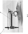
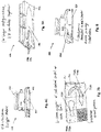
- FIGS. 1A-1B illustrate 180° rotated views of an embodiment of an electroadhesion gripper 104 comprising a robotic actuator 106 and an electroadhesion capture element 105.
- the robotic actuator 106 for example optionally comprises a robotic arm operatively coupled to the capture element 105 such that movement of the robotic arm 106 moves the capture element 105.
- the capture element 105 comprises an electroadhesion surface or plate.
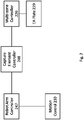
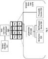
- FIG. 2 shows a box diagram of an embodiment of an electroadhesion gripper apparatus.
- the electroadhesion gripper comprises a robotic actuator and a capture element, for example an electroadhesion surface or plate.
- the electroadhesion plate optionally further comprises one or more individually controllable zones of the electroadhesion.
- the electroadhesion plate for example comprises a single electroadhesion zone.
- the electroadhesion plate comprises two electroadhesion zones. It will be understood by one skilled in the art that the electroadhesion plate comprises as many electroadhesion zones as required for the manufacture of an article from a plurality of article components.
- the electroadhesion zones are separable from one another such that the electroadhesion plate has replaceable segments or zones.
- the electroadhesion gripper comprises a capture element controller 248 in communication with the robotic actuator controller 247 comprising systems for motion control 230 as previously described herein.
- the capture element controller 248 is optionally in communication with the multi-zone controller system 226.
- the multi-zone controller system 226 individually controls the actuation of the electroadhesion zones in some embodiments.
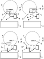
- FIGS. 3A-3H illustrate an embodiment of an electroadhesion manufacturing system in action.
- the electroadhesion system comprises a first platform 301, an electroadhesion gripper 304 comprising a robotic actuator 306 coupled to a capture element 305, and a second platform 302.
- the first platform 301 for example is a turntable.
- the second platform 302 for example is a conveyor.
- the robotic actuator 306 for example optionally comprises a robotic arm.
- the capture element 305 for example optionally comprises an electroadhesion surface or plate.
- the electroadhesion surface 305 optionally further comprises one or more individually actuating electroadhesion zones, for example a first electroadhesion zone and a second electroadhesion zone.
- the system is substantially similar to any of the embodiments described herein.
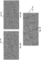
- FIG. 3A shows the electroadhesion manufacturing system after a first 303A and a second article component 303B on a first platform 301 have been delivered to the robot-side.
- FIG. 3B shows the electroadhesion gripper 304 moving to capture the first article component 303A.
- the system for example precisely positions the gripper 304 so as to capture the first article component 303A from the first predetermined capture location. Capture of the first article component 303A optionally further comprises activating the first electroadhesion zone but not the second electroadhesion zone.
- FIG. 3C shows the electroadhesion gripper 304 selectively picking up the first article component 303A but not the second article component 303B.
- FIG. 3D shows the electroadhesion gripper 304 moving to capture the second article component 303B.
- the system for example precisely positions the gripper 304 so as to capture the second article component 303B from the second predetermined capture location. Capture of the second article component 303B optionally further comprises activating the second electroadhesion zone while maintaining activation of the first electroadhesion zone so as to have both the first and the second article components 303A, 303B captured by the gripper 304 simultaneously as shown in FIG. 3E.
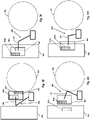
- FIG. 3F shows the system after the electroadhesion gripper 304 has moved the first and second article components 303A, 303B to a position above the second platform 302.
- the system for example optionally positions the robotic actuator 306 so that the first article component 303A is precisely placed over the first predetermined location.
- the gripper 304 releases the first article component 303A by deactivating the first electroadhesion zone while maintaining activation of the second electroadhesion zone so as to selectively release the first article component 303A but not the second article component 303B.
- FIG. 3G shows the release of the first article component 303A onto the second platform 302 while the second article component 303B is retained on the electroadhesion gripper 304.
- FIG. 3H shows the release of the second article component 303B onto the second platform 302.
- the system for example positions the robotic actuator 306 so that the second article component 303B is precisely placed over the second predetermined location.
- the gripper 304 optionally releases the second article component 303B by deactivating the second electroadhesion zone to form at least a portion of an assembled article.
- the system further detects the presence of one or more of the first or second article components 303A, 303B as described herein.
- the first and second article components 303A, 303B are placed at the first and second predetermined capture locations such that the gripper 304 simultaneously captures the first and the second article components 303A, 303B by simultaneously activating both of the first and the second electroadhesion zones.
- the first and second article components 303A, 303B are roughly placed at the first and second predetermined capture locations, respectively, by the user.
- a vision system (not shown) coupled to the electroadhesion manufacturing system (e.g., in communication with the gripper 304, robotic actuator 306, controller(s), or other components of the system) is used to determine the actual positions of the first and second article components 303A, 303B.
- the gripper 304 captures the first and second article components 303A, 303B and the system uses the determined positions and the predetermined release locations (relative to other article components) to inform their placement on the first and second predetermined release locations, respectively. Release is aided by the cessation of negative pressure and/or application of positive pressure as described herein.
- the negative pressure is deactivated prior to, simultaneously with, or after cessation of electroadhesion and/or reversal of the electrode voltage as described herein.
- positive pressure is applied prior to, simultaneously with, or after cessation of electroadhesion and/or reversal of the electrode voltage as described herein.
- Cessation of negative pressure (and/or application of positive pressure) and electroadhesion activation/deactivation can be done in concert with movement or positioning of the gripper 304 by the robotic actuator 306. This may further be combined with the application of the mechanical ejection/release mechanism described herein.
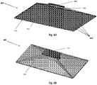
- FIGS. 4A-4C illustrate various embodiments of an electroadhesion gripper.
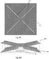
- the electroadhesion gripper apparatus 405 comprises an electroadhesive plate 451 having a contact surface 452 for capturing one or more target objects (also referred to herein as article components) with electroadhesion, the electroadhesive plate 451 comprising a one or more electroadhesive zones 456, wherein electroadhesion in each electroadhesive zone 456 is separately activated and a controller (as described further herein) configured to individually activate or deactivate electroadhesion in each of the electroadhesive zones 456.
- FIG. 4A shows an embodiment of an electroadhesion gripper with a single electroadhesion zone 456.
- the electroadhesion plate 451 comprises a plurality of electrodes 455 and is operatively attached to the robotic actuator.
- FIG. 4B shows a top view of the embodiment of FIG. 4A highlighting the housing 454 and connection to the robotic actuator 453.
- FIG. 4C shows an exemplary embodiment of an electroadhesion gripper with multiple electroadhesion zones 456 for selective capture and release of multiple article components.
- this multi-zone implementation enables a single-pick of a plurality of article components off of the first platform followed by multiple individuated placements of each article component onto the second platform. The multi-zone implementation thereby reduces the number of motion segments needed to complete the assembled article when compared to accomplishing the assembly with a single-zone gripper.
- the electroadhesion plate 451 comprises six (6) electroadhesion zones 456 as depicted herein. It will be understood however that the capture element 405 comprises any number of electroadhesion zones 456 depending on the manufacturing requirements of the article assembly.
- FIG. 5 shows a schematic diagram of an embodiment of an electroadhesion gripper 504 with multiple electroadhesion zones 556.
- a tool controller microprocessor 560 (also referred to herein as a Tool Controller), for example a multi-zone controller, is in communication with a master controller, for example a service interface 557.
- a service interface 557 on the controller wirelessly receives data from the Tool Controller 560.
- the pneumatic control 559 for the gripper 504 as a whole is controlled by the Tool Controller 560.
- the Tool Controller 560 is further in communication with the various components of each electroadhesion zone 556 on the electroadhesion gripper 504.
- the electroadhesion gripper 504 for example comprises a 2x4 rectangular array of eight (8) electroadhesion zones 556. Each electroadhesion zone 556 is further controlled by a dedicated microcontroller 526 in communication with one or more of the electroadhesion actuation control 529 and pressure sensor 558 for electroadhesion article component presence sensing. Detecting the presence of an article component for example optionally comprises measuring at the one or more of the electroadhesive zones 556 a change in pressure. Such detection occurs when pneumatic controls 559 are embedded in the gripper 504 by embedding an air pressure sensor 558 in the electroadhesion zone 556 to measure changes in pressure in the zone 556 when the article component comes into contact with the capture element surface.
- the communication between the microcontroller 526 and the tool controller 560 for example is wireless.
- the Tool Controller 560 is optionally further in communication with a pneumatic control system 559 for application of negative or positive pressure during capture or release of an article component.
- the Tool Controller 560 is configured to communicate with the master system controller 215 in order to detect capture of one or more target objects in one or more electroadhesive zones 556 by air pressure sensor 558.
- the electroadhesive zone 556 for example optionally comprises a consumable cartridge that snaps into the multi-zone tool controller receptacle.
- a microcontroller 526 for example, a PIC microcontroller from Microchip, in each zone 556 controls the electrode voltage.
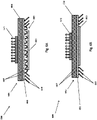
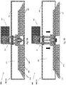
- FIGS. 6A-6C , 7A-7B, and 8 show various embodiments of an electroadhesion gripper 604, 804 comprising negative pressure ports 667, 767 to facilitate capture and release of an article component 603, 703.
- the electroadhesion gripper capture element 605, 705 comprises an electroadhesive plate 651, 751, 851 with a plurality of ports 667, 767 thereon, the plurality of ports 667, 767 configured to apply negative pressure 668 to facilitate capture of the one or more target objects 603, 703, for example one or more article components.
- the plurality of ports 667, 767 is further configured to apply positive pressure to facilitate release of the captured one or more target objects 603, 703.
- the plurality of ports 667, 767 is coupled to one or more negative pressure sources, for example, a prismatic or cuboid vacuum distributor, a fan, a pump, a turbine, a venturi, or any combination thereof.
- the one or more negative pressure sources is generated on the gripper 604, 804.
- the one or more negative pressure sources may be activated and/or deactivated independently from or simultaneously with one another. Application of negative pressure may increase the resistance of the one or more target objects 603, 703 to "peeling" off of the electroadhesive plate 651, 751, 851.
- the plurality of ports 667, 767 is configured to allow airflow through the electroadhesive plate 651, 751, 851 when the vacuum supply is activated (e.g., switched on). In many instances, the plurality of ports 667, 767 are oriented adjacent the contact surface of the electroadhesive plate 651, 751, 851.
- the plurality of negative pressure ports 667, 767 for example comprises more than four negative pressure ports 667, 767.
- the plurality of ports comprises five or more ports.
- the plurality of ports comprises at least seven ports.
- the plurality of ports comprises at least ten ports.
- the plurality of ports comprises at least twenty ports.
- the plurality of ports comprises at least thirty ports.
- the plurality of ports comprises at least forty ports.
- the plurality of ports comprises at least fifty ports.
- the plurality of ports comprises at least sixty ports.
- the plurality of ports comprises at least seventy ports.
- the plurality of ports comprises at least eighty ports.
- the plurality of ports comprises at least ninety ports. In some embodiments, the plurality of ports comprises at least one hundred ports. In some embodiments, the plurality of ports comprises at least two hundred ports. In some embodiments, the plurality of ports comprises at least three hundred ports. In some embodiments, the plurality of ports comprises at least four hundred ports. In some embodiments, the plurality of ports comprises at least five hundred ports. In some embodiments, the plurality of ports comprises at least six hundred ports. In some embodiments, the plurality of ports comprises at least seven hundred ports. In some embodiments, the plurality of ports comprises at least eight hundred ports. In some embodiments, the plurality of ports comprises at least nine hundred ports. In some embodiments, the plurality of ports comprises at least one thousand ports.
- the plurality of ports comprises at least two thousand ports. In some embodiments, the plurality of ports comprises around five to around one hundred ports. In some embodiments, the plurality of ports comprises around five to around ten ports. In some embodiments, the plurality of ports comprises around five to around twenty ports. In some embodiments, the plurality of ports comprises a range of around ten to around twenty ports. In some embodiments, the plurality of ports comprises a range of about five to about thirty ports. In some embodiments, the plurality of ports comprises a range of around ten to thirty ports. In some embodiments, the plurality of ports comprises a range of around twenty to thirty ports. In some embodiments, the plurality of ports comprises a range of about five to about forty ports.
- the plurality of ports comprises a range of around ten to forty ports. In some embodiments, the plurality of ports comprises a range of around twenty to forty ports. In some embodiments, the plurality of ports comprises around thirty to around forty ports. In some embodiments, the plurality of ports comprises a range of about five to about fifty ports. In some embodiments, the plurality of ports comprises a range of around ten to fifty ports. In some embodiments, the plurality of ports comprises a range of around twenty to fifty ports. In some embodiments, the plurality of ports comprises around thirty to around fifty ports. In some embodiments, the plurality of ports comprises around forty to around fifty ports. In some embodiments, the plurality of ports comprises a range of about five to about sixty ports.
- the plurality of ports comprises a range of around ten to sixty ports. In some embodiments, the plurality of ports comprises a range of around twenty to sixty ports. In some embodiments, the plurality of ports comprises around thirty to around sixty ports. In some embodiments, the plurality of ports comprises around forty to around sixty ports. In some embodiments, the plurality of ports comprises around fifty to around sixty ports. In some embodiments, the plurality of ports comprises a range of about five to about sixty ports. In some embodiments, the plurality of ports comprises a range of around ten to sixty ports. In some embodiments, the plurality of ports comprises a range of around twenty to sixty ports. In some embodiments, the plurality of ports comprises around thirty to around sixty ports.
- the plurality of ports comprises around forty to around sixty ports. In some embodiments, the plurality of ports comprises around fifty to around sixty ports. In some embodiments, the plurality of ports comprises a range of about five to about seventy ports. In some embodiments, the plurality of ports comprises a range of around ten to seventy ports. In some embodiments, the plurality of ports comprises a range of around twenty to seventy ports. In some embodiments, the plurality of ports comprises around thirty to around seventy ports. In some embodiments, the plurality of ports comprises around forty to around seventy ports. In some embodiments, the plurality of ports comprises around fifty to around seventy ports. In some embodiments, the plurality of ports comprises around sixty to around seventy ports.
- the plurality of ports comprises a range of about five to about eighty ports. In some embodiments, the plurality of ports comprises a range of around ten to eighty ports. In some embodiments, the plurality of ports comprises a range of around twenty to eighty ports. In some embodiments, the plurality of ports comprises around thirty to around eighty ports. In some embodiments, the plurality of ports comprises around forty to around eighty ports. In some embodiments, the plurality of ports comprises around fifty to around eighty ports. In some embodiments, the plurality of ports comprises around sixty to around eighty ports. In some embodiments, the plurality of ports comprises around seventy to around eighty ports. In some embodiments, the plurality of ports comprises a range of about five to about ninety ports.
- the plurality of ports comprises a range of around ten to ninety ports. In some embodiments, the plurality of ports comprises a range of around twenty to ninety ports. In some embodiments, the plurality of ports comprises around thirty to around ninety ports. In some embodiments, the plurality of ports comprises around forty to around ninety ports. In some embodiments, the plurality of ports comprises around fifty to around ninety ports. In some embodiments, the plurality of ports comprises around sixty to around ninety ports. In some embodiments, the plurality of ports comprises around seventy to around ninety ports. In some embodiments, the plurality of ports comprises around eighty to around ninety ports.
- the plurality of ports comprises a range of about five to about one hundred ports. In some embodiments, the plurality of ports comprises a range of around ten to one hundred ports. In some embodiments, the plurality of ports comprises a range of around twenty to one hundred ports. In some embodiments, the plurality of ports comprises around thirty to around one hundred ports. In some embodiments, the plurality of ports comprises around forty to around one hundred ports. In some embodiments, the plurality of ports comprises around fifty to around one hundred ports. In some embodiments, the plurality of ports comprises around sixty to around one hundred ports. In some embodiments, the plurality of ports comprises around seventy to around one hundred ports. In some embodiments, the plurality of ports comprises around eighty to around one hundred ports.
- the plurality of ports comprises around ninety to around one hundred ports. In some embodiments, the plurality of ports comprises around five to around one thousand ports. In some embodiments, the plurality of ports comprises around five to around two hundred ports. In some embodiments, the plurality of ports comprises around five to around three hundred ports. In some embodiments, the plurality of ports comprises a range of around ten to around four hundred ports. In some embodiments, the plurality of ports comprises a range of about five to about five hundred ports. In some embodiments, the plurality of ports comprises a range of about five to about six hundred ports. In some embodiments, the plurality of ports comprises a range of about five to about seven hundred ports.
- the plurality of ports comprises a range of about five to about eight hundred ports. In some embodiments, the plurality of ports comprises a range of about five to about nine hundred ports. In some embodiments, the plurality of ports comprises a range of about five to about one thousand ports. In some embodiments, the plurality of ports comprises a range of about five to about two thousand ports. In some embodiments, the plurality of ports comprises a range of around one hundred to two hundred ports. In some embodiments, the plurality of ports comprises a range of around one hundred to three hundred ports. In some embodiments, the plurality of ports comprises a range of around one hundred to four hundred ports. In some embodiments, the plurality of ports comprises a range of around one hundred to five hundred ports.
- the plurality of ports comprises a range of around one hundred to six hundred ports. In some embodiments, the plurality of ports comprises a range of around one hundred to seven hundred ports. In some embodiments, the plurality of ports comprises a range of around one hundred to eight hundred ports. In some embodiments, the plurality of ports comprises a range of around one hundred to nine hundred ports. In some embodiments, the plurality of ports comprises a range of around one hundred to one thousand ports. In some embodiments, the plurality of ports comprises a range of around one hundred to two thousand ports. In some embodiments, the plurality of ports comprises a range of around two hundred to three hundred ports. In some embodiments, the plurality of ports comprises a range of around two hundred to four hundred ports.
- the plurality of ports comprises a range of around two hundred to five hundred ports. In some embodiments, the plurality of ports comprises a range of around two hundred to six hundred ports. In some embodiments, the plurality of ports comprises a range of around two hundred to seven hundred ports. In some embodiments, the plurality of ports comprises a range of around two hundred to eight hundred ports. In some embodiments, the plurality of ports comprises a range of around two hundred to nine hundred ports. In some embodiments, the plurality of ports comprises a range of around two hundred to one thousand ports. In some embodiments, the plurality of ports comprises a range of around two hundred to two thousand ports. In some embodiments, the plurality of ports comprises a range of around three hundred to four hundred ports.
- the plurality of ports comprises a range of around three hundred to five hundred ports. In some embodiments, the plurality of ports comprises a range of around three hundred to six hundred ports. In some embodiments, the plurality of ports comprises a range of around three hundred to seven hundred ports. In some embodiments, the plurality of ports comprises a range of around three hundred to eight hundred ports. In some embodiments, the plurality of ports comprises a range of around three hundred to nine hundred ports. In some embodiments, the plurality of ports comprises a range of around three hundred to one thousand ports. In some embodiments, the plurality of ports comprises a range of around three hundred to two thousand ports. In some embodiments, the plurality of ports comprises a range of around four hundred to five hundred ports.
- the plurality of ports comprises a range of around four hundred to six hundred ports. In some embodiments, the plurality of ports comprises a range of around four hundred to seven hundred ports. In some embodiments, the plurality of ports comprises a range of around four hundred to eight hundred ports. In some embodiments, the plurality of ports comprises a range of around four hundred to nine hundred ports. In some embodiments, the plurality of ports comprises a range of around four hundred to one thousand ports. In some embodiments, the plurality of ports comprises a range of around four hundred to two thousand ports. In some embodiments, the plurality of ports comprises a range of around five hundred to six hundred ports. In some embodiments, the plurality of ports comprises a range of around five hundred to seven hundred ports.
- the plurality of ports comprises a range of around five hundred to eight hundred ports. In some embodiments, the plurality of ports comprises a range of around five hundred to nine hundred ports. In some embodiments, the plurality of ports comprises a range of around five hundred to one thousand ports. In some embodiments, the plurality of ports comprises a range of around five hundred to two thousand ports. In some embodiments, the plurality of ports comprises a range of around six hundred to seven hundred ports. In some embodiments, the plurality of ports comprises a range of around six hundred to eight hundred ports. In some embodiments, the plurality of ports comprises a range of around six hundred to nine hundred ports. In some embodiments, the plurality of ports comprises a range of around six hundred to one thousand ports.
- the plurality of ports comprises a range of around six hundred to two thousand ports. In some embodiments, the plurality of ports comprises a range of around seven hundred to eight hundred ports. In some embodiments, the plurality of ports comprises a range of around seven hundred to nine hundred ports. In some embodiments, the plurality of ports comprises a range of around seven hundred to one thousand ports. In some embodiments, the plurality of ports comprises a range of around seven hundred to two thousand ports. In some embodiments, the plurality of ports comprises a range of around eight hundred to nine hundred ports. In some embodiments, the plurality of ports comprises a range of around eight hundred to one thousand ports. In some embodiments, the plurality of ports comprises a range of around eight hundred to two thousand ports.
- the plurality of ports comprises a range of around nine hundred to one thousand ports. In some embodiments, the plurality of ports comprises a range of around nine hundred to two thousand ports. In some embodiments, the plurality of ports comprises a range of around one thousand to around two thousand ports. In some embodiments, the plurality of ports comprises a range of around one thousand one hundred to around two thousand ports. In some embodiments, the plurality of ports comprises a range of around one thousand two hundred to around two thousand ports. In some embodiments, the plurality of ports comprises a range of around one thousand three hundred to around two thousand ports. In some embodiments, the plurality of ports comprises a range of around one thousand four hundred to around two thousand ports.
- the plurality of ports comprises a range of around one thousand five hundred to around two thousand ports. In some embodiments, the plurality of ports comprises a range of around one thousand six hundred to around two thousand ports. In some embodiments, the plurality of ports comprises a range of around one thousand seven hundred to around two thousand ports. In some embodiments, the plurality of ports comprises a range of around one thousand eight hundred to around two thousand ports. In some embodiments, the plurality of ports comprises a range of around one thousand nine hundred to around two thousand ports. It will be understood that the plurality of ports may comprise any number of ports in order generate negative pressure at the surface of the capture element.
- FIG. 6A shows an embodiment of an electroadhesion gripper 604 comprising negative pressure ports 667 that facilitate capture of an article component 603 without direct contact between the article component 603 and the electroadhesion gripper 604.
- the electroadhesion gripper 604 comprises a capture element 605, for example an electroadhesive plate 651, with a plurality of ports 667 thereon, and a housing 654.
- the housing 654 for example extends from the electroadhesive plate 651 to the connection 671 to one or more of the robotic actuator and negative pressure source and forms a plenum 674 therebetween (as shown in FIG. 9A ).
- the housing 654 for example is optionally cuboid shaped, with contact between the electroadhesive plate 651 and the housing 654 forming one or more of a right angle and an obtuse angle.
- the housing 654 for example is curved and/or forms a right angle where the housing 654 contacts the connection 671 to the negative pressure source.
- the housing 654 is for example optionally prismatic.
- the applied negative pressure 668 for example facilitates capture of the one or more target objects 603 by generating a lower dynamic pressure region 669 between the contact surface 652 and the one or more target objects 603 to facilitate lifting of the one or more target objects 603.
- FIG. 6B shows another embodiment of an electroadhesion gripper 604 comprising negative pressure ports 667 that facilitate capture of an article component 603 utilizing direct contact between the article component 603 and the electroadhesion gripper 604.
- the applied negative pressure 668 for example facilitates capture of the one or more target objects 668 by generating a static negative pressure within the one or more ports 667 to hold the captured one or more target objects 603 contacting the contact surface 652.
- FIG. 6C shows a side-view of an embodiment of an electroadhesion gripper 604 comprising negative pressure ports 667.
- the electroadhesion gripper 604 comprises an electroadhesive plate 651 with a plurality of ports 667 thereon, any one or more of the plurality of ports 667 configured to apply negative pressure 668 to facilitate capture of the one or more target objects 603, for example one or more article components. Any one or more of the plurality of ports 667 is further configured to apply positive pressure to facilitate release of the captured one or more target objects 603.
- any one or more of the plurality of ports 667 is coupled to one or more negative pressure sources 676, for example a prismatic or cuboid vacuum distributor, a fan, a pump, a turbine, a venturi, or any combination thereof.
- the one or more target objects 603 and applied negative pressure 668 have not been shown for clarity.
- FIGS. 7A-7B illustrates an embodiment of an electroadhesion gripper capture element 705 comprising negative pressure or vacuum ports 767 with multiple electroadhesion zones 756, wherein electroadhesion and the negative pressure ports 767 in each zone 756 are selectively controllable to facilitate capture and release of one or more article components 703.
- the plurality of ports 767 comprises a plurality of port regions 775, wherein each port region 775 is configured to be separately actuated and complementary to each individuated electroadhesive zone 756 to facilitate selective capture or release of the one or more target objects 703 from the electroadhesive zone 756.
- the plurality of vacuum ports 767 comprises a first zone of vacuum ports 775A for capturing a first article component 703A and a second zone of vacuum ports 775B for capturing a second article component 703B.
- each electroadhesion zone 756 comprises a zone of vacuum ports 775.
- the first and second zones of vacuum ports 775A, 775B are separately controlled to capture or release one or more of the first and second article components 703A, 703B.
- the vacuum ports 767 in each zone of vacuum ports 775 are connected to a vacuum supply.
- the number of vacuum supplies matches the number of zones of vacuum ports 775 such that each zone 775 is connected to a dedicated vacuum supply embedded in each zone 775, with each vacuum supply being individually controllable so as to control the vacuum 768 of each zone independently of the other zones 775.
- a first vacuum supply is embedded in the first zone 775A and a second vacuum supply is embedded in the second zone 775B such that the first and second vacuum supplies are independent and do not connect.
- the vacuum supplies are fans/propellers embedded in each zone 775 hence providing a programmable vacuum source wholly independent of the vacuum provided in other zones 775.
- the vacuum ports 767 span across the upper and lower surfaces of the contact surface or plate 751.
- the vacuum ports 767 have a uniform diameter throughout. In some embodiments, the vacuum ports 767 are oriented transverse or perpendicularly to the upper and lower surfaces of the contact surface or plate 751. In some embodiments, the vacuum ports 767 are distributed throughout the electroadhesive surface 751 such that the ports 767 are between and/or on top of the electrodes of the electroadhesive surface 751.
- each electroadhesion zone 756 comprising a zone of vacuum ports 775 is separable from each other zone 756 such that the electroadhesion plate 751 has replaceable segments or zones 756.
- each replaceable segment 756 of the electroadhesion plate 751 comprises an electroadhesion zone 756 with a zone of vacuum ports 775 and a housing 754 with connection to the gripper 704 (for example as illustrated in FIG. 6A ), such that the housing 754 and electroadhesion zone 756 are a detachable unit.
- the contact surface 752 of the electroadhesion plate 751 is non-planar. In many embodiments, the contact surface 752 of the electroadhesion plate 751 is compressible, for example being made of a compressible material. In some embodiments the contact surface 752 of the electroadhesion plate 751 is a compressible planar surface. In some embodiments, the contact surface 752 of the electroadhesion plate 751 is a compressible non-planar surface. In some embodiments, the contact surface 752 of the electroadhesion plate 751 is a non-compressible non-planar surface.
- the contact surface 751 of one or more of an electroadhesion zone 756 is non-planar.
- the contact surface 751 of the electroadhesion zone 756 is compressible, for example being made of a compressible material, having a compressible coating, and/or being mounted via a compressible interface.
- the contact surface 752 of the electroadhesion zone 756 is a compressible planar surface.
- the contact surface 752 of the electroadhesion zone 756 is a compressible non-planar surface.
- the contact surface 752 of the electroadhesion zone 756 is a non-compressible non-planar surface.
- the plurality of electroadhesion zones 756 in the gripper are arranged so as to be coplanar. In some embodiments the plurality of electroadhesion zones 756 in the gripper are arranged so as to be not coplanar-for example, specifically arranged so as to improve gripping force and article flatness following release onto the second platform.
- This hybrid approach enables the gripper to leverage electroadhesion on non-porous and/or porous article components, for example a fabric mesh, that exhibit good electron mobility, for example, conductors or weakly-conductive insulators.
- This approach further optionally leverages vacuum to acquire article components that do not have sufficient electron mobility or do not create enough normal force to flatten deformed article components.
- the combination of electroadhesion, vacuum, and/or mechanized release allows the hybrid gripper to deliver deterministic acquisition and release times across a broad range of article materials.
- the vacuum and electroadhesion act in such a way as to aid each other.
- the vacuum brings the target object/article component closer to the electroadhesive surface, which in turn enhances the electroadhesive force.
- Electroadhesion allows for better sealing of the target object against the electroadhesive surface, thereby enhancing the vacuum forces on the target object.
- FIG. 8 shows a side view of an embodiment of an electroadhesion gripper comprising negative pressure ports 867 wherein the electroadhesion gripper plate 851 is a removable cartridge.
- FIGS. 9A-9B show schematics of an embodiment of an electroadhesion gripper 904 comprising an electroadhesion plate 951 with negative pressure ports 967, and optional mechanical separation mechanism 970, to facilitate capture and release of an article component.
- the electroadhesion plate 951 with negative pressure ports 967 may be substantially similar to other embodiments described herein.
- the mechanical separation mechanism comprises a netting 965 configured to be placed over the contact surface of the electroadhesion plate 951.
- the netting 965 for example is configured to separate from the contact surface to facilitate release of one or more article components.
- the gripper 904 optionally further comprises a linear actuator 906 coupled to the electroadhesive plate 951 and the netting 965 to separate the netting 965 and the contact surface from one another.
- the ejection filaments 965 rest on the contact surface of the electroadhesion plate 951 when retracted.
- the contact surface of the electroadhesion plate 951 comprises surface indentations that allow the ejection filaments 965 to be housed (e.g., inlaid) within the indentation such that the contact surface of the electroadhesion plate 951 comprises a flat surface without any offsetting due to the ejection filaments 965.
- FIG. 9A shows a cross-section of schematic of an embodiment of an electroadhesion gripper 904 comprising an electroadhesion plate 951 with negative pressure ports 967 and optional mechanical separation mechanism 970, with mechanical separation mechanism 970 retracted.
- the gripper 904 comprises a plenum 974 formed between the electroadhesion plate 951 and the housing 954 of the capture element 905. When retracted as shown here, the ejector 970 is housed in the plenum 974.
- the capture element 905 is connected to the robotic actuator 906 via a linkage system 953.
- FIG. 9B shows a cross-section of an embodiment of an electroadhesion gripper 904 comprising negative pressure ports 967 and optional mechanical separation mechanism 970 with mechanical separation mechanism 970 extended. Extension of the ejector blades 973 through the electroadhesion plate 951 mechanically separates the capture element 905 from a captured article component, thereby facilitating the release of said article component from the capture element 905.
- FIG. 9C shows a top view of the electroadhesion plate 951.
- the electroadhesion plate 951 comprises slots 971 through which the ejector blades 973 are extended to contact the article component and facilitate release of said article component from the capture element 905.
- FIG. 9D shows a perspective view of an embodiment of a mechanical separation mechanism 970 as used in FIG. 9A-9D .
- the mechanical separation mechanism 970 comprises a plurality of ejector blades 973, for example four ejector blades 973, which are arranged so as to precisely correspond with the slots 971 on the electroadhesion plate 951.
- the ejector blades 973 for example form a cross.
- the ejector blades 973 are coupled for a netting or filaments 965 which are in contact with the captured article component. Actuation of the ejector blades 973 through the electroadhesion plate 951 facilitates release of the article component from the contact surface 952 of the electroadhesion plate 951.
- the electroadhesion gripper 904 comprises an electroadhesion plate 951 with a plurality of electroadhesion zones 956 comprising a plurality of negative pressure ports 967 therein as previously described herein.
- each electroadhesion zone 956 comprises a mechanical separation mechanism 970, for example, a netting 965, such that each zone 956 is individuated in such a way that the capture and release modalities of each electroadhesion zone 956 of the capture element 905 are activated independently from every other zone 956.
- each zone 956 is individuated in such a way that the capture and release modalities of each electroadhesion zone 956 of the capture element 905 are activated independently from every other zone 956.
- FIGS. 10A-10C show exemplary embodiments of an electroadhesion gripper plate 1051 with various patterns for electrode and negative pressure port integration.
- FIG. 10A shows an embodiment of an electroadhesion plate 1051 or electroadhesion zone 1056 wherein the vacuum ports and electroadhesion electrodes form concentric rings.
- FIG. 10B shows an embodiment of an electroadhesion plate 1051 or electroadhesion zone 1056 wherein the vacuum ports and electroadhesion electrodes form chains of donuts and squiggles.
- FIG. 10A shows an embodiment of an electroadhesion plate 1051 or electroadhesion zone 1056 wherein the vacuum ports and electroadhesion electrodes form chains of donuts and squiggles.
- FIG. 10A shows an embodiment of an electroadhesion plate 1051 or electroadhesion zone 1056 wherein the vacuum ports and electroadhesion electrodes form chains of donuts and squiggles.
- FIG. 10C shows an embodiment of an electroadhesion plate 1051 or electroadhesion zone 1056 wherein the vacuum ports and electroadhesion electrodes are more traditionally patterned, for example with parallel lines, in a comb pattern, or interdigitated. Other shapes such as hexagons, rectangles, octagons, serpentine patterns, or other geometric shapes are also contemplated. It is contemplated that the ports are in the conductive traces or in the space between traces. A small region without electrodes is optionally provided about the ports to help with HV insulation. The ports for example are all located in the same polarity electrode to help prevent shorting from one polarity to another.
- FIG. 11 shows a method 1100 of capturing and releasing a plurality of target objects using an electroadhesion manufacturing system comprising an electroadhesion gripper as described previously herein.
- the method may use one or more of the systems and apparatus described herein.
- the first article component is captured by a first electroadhesion zone and the second article component is capture by a second electroadhesion zone.
- Capture of the first article component for example comprises one or more of activation of electroadhesion within the first electroadhesion zone (step 1101A) and application of negative pressure at the first electoradhesion zone (step 1101B).
- Capture of the second article component for example comprises one or more of activation of electroadhesion within the second electroadhesion zone (step 1101A) and application of negative pressure at the second electroadhesion zone (step 1101B). Capture of the first and second article components occurs simultaneously.
- the capture of the first article component is detected by a first pressure sensor embedded in the first electroadhesion zone.
- the capture of the second article component is detected by a second pressure sensor embedded in the second electroadhesion zone.
- the first article component is released from the first electroadhesion zone while the second article component is retained at the second electroadhesion zone.
- Release of the first article component from the first electroadhesion zone for example comprises one or more of cessation of negative pressure at the first electroadhesion zone (step 1104A), application of positive pressure the first electroadhesion zone (step 1104B), and separation of a netting from the first electroadhesion zone (step 1104C).
- release of the first article component is detected by the first pressure sensor.
- step 1106 retention of the second article component is detected by the second pressure sensor.
- the second article component is released from the second electroadhesion zone.
- Release of the second article component from the second electroadhesion zone for example comprises any one or more of the release mechanisms described previously herein.
- release of the second article component is detected by the second pressure sensor.
- step 1109 the previous steps are repeated for multiple article components.
- steps above show a method 1100 of capturing and releasing a plurality of target objects using an electroadhesion manufacturing system comprising an electroadhesion gripper in accordance with embodiments
- a person of ordinary skill in the art will recognize many variations based on the teaching described herein.
- the steps may be completed in a different order. Steps may be added or deleted. Some of the steps may comprise sub-steps. Many of the steps may be repeated as often as necessary to assemble at least a part of an article.
- Step 1102 optionally occurs such that the first and second article components are captured at different times.
- additional article components are for example detected and captured simultaneously with the detection and capture of the first and second article components, respectively.
- steps above show a method 1100 of capturing and releasing objects in accordance with embodiments
- a person of ordinary skill in the art will recognize many variations based on the teaching described herein.
- the steps may be completed in a different order. Steps may be added or deleted. Some of the steps may comprise sub-steps. Many of the steps may be repeated as often as beneficial.
- one or more of the steps of the method 1100 are performed with circuitry of the various components described herein.
- the circuitry is programmed to provide one or more of the steps of the method 1100, and the program comprises program instructions stored on a computer readable memory or programmed steps of the logic in the circuitry.
- FIG. 12 shows a method 1200 of manufacturing an article using an electroadhesion manufacturing system comprising an electroadhesion gripper as described previously herein.
- the method may use one or more of the systems and apparatus described herein.
- the capture element is placed over the first article component.
- Placement of the capture element for example comprises one or more of moving a robotic arm (step 1201A) and aligning the capture element to a first predetermined capture location (step 1201B).
- the first article component is captured by the first electroadhesion zone.
- Capture for example comprises one or more of activation of electroadhesion within the first electroadhesion zone (step 1202A) and application of negative pressure at the first electroadhesion zone (step 1202B).
- the application of electroadhesion, negative pressure, or the combination thereof is selected based on the type of article component being handled.
- the capture element is placed over the second article component.
- Placement of the capture element for example comprises one or more of moving the robotic arm (step 1203A) and aligning the capture element to a second predetermined capture location (step 1203B).
- the second article component is captured by the second electroadhesion zone.
- Capture for example comprises one or more of activation of electroadhesion within the second electroadhesion zone (step 1204A) and application of negative pressure at the second electroadhesion zone (step 1204B).
- the article components are moved to a position over the second platform. Movement of the article components for example comprises one or more of moving the robotic arm (step 1205A) and aligning the capture element to the first predetermined location (step 1205B).
- the first article component is released from the first electroadhesion zone while the second article component is retained at the second electroadhesion zone.
- Release of the first article component from the first electroadhesion zone for example comprises one or more of cessation of negative pressure at the first electroadhesion zone (step 1206A), application of positive pressure the first electroadhesion zone (step 1206B), and separation of a netting from the first electroadhesion zone (step 1206C).
- the second article component is released onto the second platform.
- Release of the second article component from the second electroadhesion zone for example optionally comprises moving the robotic arm to align the capture element with a second predetermined location of the second platform as previously described herein.
- Release of the second article component from the second electroadhesion zone for example comprises any one or more of the release mechanisms described previously herein.
- step 1208 the previously described steps are repeated for multiple article components.
- steps above show a method of manufacturing an article using an electroadhesion manufacturing system comprising an electroadhesion gripper in accordance with embodiments
- a person of ordinary skill in the art will recognize many variations based on the teaching described herein.
- the steps may be completed in a different order. Steps may be added or deleted. Some of the steps may comprise sub-steps. Many of the steps may be repeated as often as necessary to assemble at least a part of an article.
- Steps 1201 and 1203 of positioning the capture element optionally occur simultaneously when the first and second article components have been placed in predetermined capture locations such that Steps 1202 and 1204 are able to be performed simultaneously to capture the first and second article components at the same time.
- additional article components are for example captured simultaneously with the capture of the first and second article components, respectively.
- steps above show a method 1200 of manufacturing an article in accordance with embodiments
- a person of ordinary skill in the art will recognize many variations based on the teaching described herein.
- the steps may be completed in a different order. Steps may be added or deleted. Some of the steps may comprise sub-steps. Many of the steps may be repeated as often as beneficial.
- one or more of the steps of the method 1200 are performed with circuitry of the various components described herein.
- the circuitry is programmed to provide one or more of the steps of the method 1200, and the program comprises program instructions stored on a computer readable memory or programmed steps of the logic in the circuitry.
Landscapes
- Engineering & Computer Science (AREA)
- Mechanical Engineering (AREA)
- Robotics (AREA)
- Manufacturing & Machinery (AREA)
- Multimedia (AREA)
- Microelectronics & Electronic Packaging (AREA)
- Chemical & Material Sciences (AREA)
- Combustion & Propulsion (AREA)
- Transportation (AREA)
- Manipulator (AREA)
- Footwear And Its Accessory, Manufacturing Method And Apparatuses (AREA)
- Specific Conveyance Elements (AREA)
- Automatic Assembly (AREA)
Description
- The mass production of products has led to many innovations over the years. Substantial developments have been made in the industrial handling of various materials and items, particularly in the area of robotics. For example, various types of robotics and other automated systems are now used in order to "pick and place" items during many manufacturing and other materials handling processes. Such robotics and other systems can include robot arms that, for example, grip, lift and/or place an item as part of a designated process. Of course, other manipulations and materials handling techniques can also be accomplished by way of such robotics or other automated systems.
- Despite many advances over the years in this field, there are limitations as to what can be handled in such a robotic or automated manner.
- Conventional robotic grippers typically use either suction or a combination of large normal and shear forces and fine control with mechanical actuation in order to grip objects. Such techniques have several drawbacks. For example, the use of suction alone tends to require smooth, clean, dry, non-porous, and generally flat surfaces, which limits the types and conditions of objects that are gripped. Suction alone also tends to require a lot of power for the pumps and can be prone to leaks at any location on a vacuum or low pressure seal, with a resulting loss of suction being potentially catastrophic. The use of mechanical actuation often requires large normal or "crushing" forces against an object, and also tends to limit the ability to robotically grip flexible, deformable, fragile, or delicate objects. Producing large forces also increases the cost of mechanical actuation. Mechanical pumps and conventional mechanical actuation with large crushing forces also often require substantial weight, which is a major disadvantage for some applications, such as the end of a robot arm where added mass must be supported. Furthermore, even when used with sturdy objects, robotic arms, mechanical claws and the like can still leave damaging marks on the surface of the object itself.
- Alternative techniques for handling items and materials also have drawbacks. For example, chemical adhesives can leave residues and tend to attract dust and other debris that reduce effectiveness. Chemical adhesives can also require a significant amount of added force to undo or overcome a grip or attachment to an object once such a chemical adhesive grip or attachment is applied, since the gripping interaction and force is typically not reversible in such instances.
- Conventional robotic grippers often do not support gripping of more than one object at a time and thus limit the speed with which operations including a plurality of objects are completed. Conventional systems are also often constrained by a requirement that said objects be fed to the robotic gripper with precise orientations by a human operator for proper "pick and place". Furthermore, conventional systems are typically large and require special fencing to protect operators from the hazards of working near high-speed robots.
- Although many systems and techniques for handling materials in an automated fashion for the manufacture of an article have generally worked well in the past, there is a desire to provide alternative and improved ways of handling items. In particular, improved automated systems, devices, and techniques are needed to enable the picking and placing or other handling of a plurality of materials including a broad spectrum of flexible and/or porous materials of various shapes and sizes that cannot be handled reliably using conventional vacuum and mechanical methods. Such materials include but are not limited to woven and knit fabric, as used in athletic footwear and apparel manufacturing, carbon fiber sheets, as used in airframe manufacture, and flexible printed circuit boards. The ability to pick up flexible materials without distorting their shape through sagging, wrinkling, or other deformation, and then place them precisely in such a way that preserves their shape is desired so as to enable automation of a variety of subsequent tasks such as welding, fusing, stitching, bonding, printing, or any other task that requires precise placement of flexible materials.
- A gripper apparatus is disclosed in U.S. Pub. No.
US 2018/0298320A1 . The gripper apparatus includes one or more projecting electroadhesive sections that can be deformed in so as to form to the surface to be gripped. The gripper apparatus also includes multiple additional gripper devices positioned in free spaces between the electroadhesive sections that are designed as suction grippers that are functionally independent of the electroadhesive sections. - U.S. Pub. No.
US 2015/0314583A1 discloses a fabric handling apparatus having a layup table, a mold and a frame supporting a fabric handling array of attractors that may be configured as electrostatic devices. The fabric handling array is adapted to transfer fabric shapes from the layup table to the mold via the electrostatic devices of the fabric handling array. - Japanese publication
JP 2000 286543A - U.S. Pub. No.
US 2010/0194012A1 discloses a substrate suction apparatus that includes an electrostatic attraction mechanism configured for holding a substrate that is to be processed. The apparatus includes a multi-layer porous dielectric body formed on a base with attraction electrodes provided between the layers of the dielectric body. A suction pump is used to draw suction through the porous dielectric body. - Provided herein are systems, apparatus, and methods of manufacturing an article using electroadhesion technology in concert with vacuum for the acquisition and release of materials.
- Provided herein are electroadhesion manufacturing systems. An exemplary electroadhesion system comprises a first platform configured to guide the placement of a first article component and an article component, a second platform having a first predetermined location for the first article component and a second predetermined location for the second article component, an electroadhesive capture element configured to capture the first and second article components placed on the first platform, and a robotic actuator coupled to the capture element to move the capture element to capture the first and second article components and to move the capture element to reposition the captured first and second article components over the first and second predetermined locations on the second platform, respectively. The capture element comprises an electroadhesive surface and one or more negative pressure sources coupled to a plurality of vacuum ports on the electroadhesive surface. The capture element releases the first and second article components onto the first and second predetermined locations, respectively. The first and second article components placed on the second platform are typically assembled into the article. The capture and/or release of the first and second article may be simultaneous or sequential. The electroadhesive surface in some embodiments comprises one or more electroadhesive plates. The electroadhesive surface alternatively or in combination comprises a first zone for capturing the first article component and a second zone for capturing the second article component. In many embodiments, the first and second zones of the electroadhesive surface are optionally separately activated to selectively capture or release one or more of the first and second article components. In some embodiments, one or more of the first and second zones of the electroadhesive surface are configured to detect a presence of one or more of the first and second article components on the first platform, respectively. In many embodiments, the capture element comprises one or more negative pressure sources coupled to the plurality of vacuum ports on the capture element. In some embodiments, the one or more negative pressure sources comprises one or more of a prismatic or cuboid vacuum distributor, a fan, a pump, a turbine, a venturi, and a propeller. In some embodiments, the presence of one or more of the first or second article components on the capture element is detected by sensing pressure changes in a plenum between the capture surface and the housing. In some embodiments, the plurality of vacuum ports comprises a first zone of vacuum ports for capturing the first article component and a second zone of vacuum ports for capturing the second article component. In some embodiments, the first and second zones of vacuum ports are separately controlled to capture or release one or more of the first and second article components. In some embodiments, the vacuum ports in each zone of vacuum ports are connected to a vacuum supply. In some embodiments, the number of vacuum supplies matches the number of zones of vacuum ports such that each zone is connected to a dedicated vacuum supply embedded in each zone, with each vacuum supply being individually controllable so as to control the vacuum of each zone independently of the other zones. For example, in an exemplary embodiment a first vacuum supply is embedded in the first zone and a second vacuum supply is embedded in the second zone such that the first and second vacuum supplies are independent and do not connect. For instance, the vacuum supplies are fans/propellers embedded in each zone hence providing a programmable vacuum source wholly independent of the vacuum provided in other zones. In many embodiments, the vacuum ports traverse the upper and lower surfaces of the contact surface or plate. In some embodiments, the vacuum ports have a uniform cross-section throughout. In some embodiments, the vacuum ports are oriented transverse or perpendicularly to the upper and lower surfaces of the contact surface or plate. In many embodiments, the electroadhesive surface (e.g. electroadhesive plate) comprises holes (also referred to herein as ports) that allow airflow through the electroadhesive surface when the vacuum supply is switched on. In many embodiments, the vacuum holes or ports are oriented adjacent to the electroadhesive surface. In many embodiments, the electroadhesive surface and the vacuum supply are turned on and off independent of one another. In many embodiments, the electroadhesive surface and the vacuum supply are turned on and off collectively with one other. In many embodiments, the capture element comprises a first zone for capturing the first article component and a second zone for capturing the second article component. In many embodiments, the robotic actuator is configured to position the capture element to sequentially capture the first and second article components on the first platform. In many embodiments, sequentially capturing the first and second article components on the first platform comprises the steps of positioning the robotic actuator so that the first article component is aligned with a first predetermined capture location on the first platform, capturing the first article component on the first predetermined capture location, repositioning the robotic actuator or the first platform so that the second article component is aligned with a second predetermined capture location on the first platform, and capturing the second article component on the second predetermined capture location. Alternatively or in combination, the robotic actuator is configured to position the capture element to simultaneously capture the first and second article components on the first platform. For instance, the robotic actuator is configured to move the capture element to sequentially position the captured first and second article components over the first and second predetermined locations on the second platform, respectively. In some embodiments, the second article component is placed directly above the first article component so as to create a stack. In some embodiments, the second platform is moved relative to the capture element such that the captured article components are released at the predetermined locations on the second platform. The robotic actuator is configured to move the capture element to simultaneously position the captured first and second article components over the first and second predetermined locations on the second platform, respectively. In many embodiments the robotic actuator comprises a robotic arm. One or more of the first and second article components comprises a textile piece, a shoe part, an automotive part, a machinery part, or a circuitry part. The article comprises, respectively, at least a portion of an article of clothing, at least a portion of a shoe, at least a portion of a machine, or at least a portion of a circuit. In many embodiments, the electroadhesion manufacturing system further comprises a controller coupled to one or more of the first platform, the second platform, the capture element, and the robotic actuator. In many embodiments, the first platform comprises a first portion configured to guide the placement of an initial set of first and second article components thereon by a user and a second portion configured to guide the placement of a subsequent set of first and second article components thereon by the user. Optionally, after the initial set of first and second article components is placed on the first portion, the first platform is moved to position the first portion closer to the capture element. In many embodiments, the capture element comprises a first zone for capturing the first article component and a second zone for capturing the second article component, the first and second zones being separately mechanically actuated to selectively capture or release one or more of the first and second article components. The capture element optionally comprises a mechanical separation mechanism configured to be advanced from a surface of the capture element to release one or more of the first and second article components.
- According to one aspect of the invention, there is provided a method of manufacturing an article with the aid of an electroadhesive capture element, as set forth in the accompanying
claim 1. An exemplary method comprises the steps of capturing a first article component placed on a first platform via electroadhesion and application of negative pressure, capturing a second article component placed on the first platform via electroadhesion and application of negative pressure, moving the captured first and second article components to a position over a second platform, releasing the captured first article component to place the first article component on a first predetermined location of the second platform, and releasing the captured second article component to place the second article component on a second predetermined location of the second platform. The first and second article components placed on the second platform are assembled into at least a portion of the article. The step or capturing the one or more of the first and second article components with electroadhesion comprises a step of placing a planar electroadhesive surface of an electroadhesive capture element over the one or more of the first and second article components and activating the electroadhesive surface. Negative pressure is applied at the electroadhesive surface of the capture element. The electroadhesive surface comprises a plurality of ports thereon through which the negative pressure is applied. In many embodiments, the electroadhesive surface comprises a first zone for capturing the first article component and a second zone for capturing the second article component. Any one or more of the first and second zones of the electroadhesive surface for example is optionally separately activated to capture or release one or more of the first or second article components. One or more of the step of releasing the captured first article component and releasing the second article component comprises a step of selectively releasing one or more of the first and second article components from the electroadhesion. In some embodiments, the first and second zones are concurrently or sequentially activated. In many embodiments, the capture element is coupled to one or more vacuum sources. In some embodiments, one or more of the capture element and the first platform comprises a first vacuum source for capturing the first article component and a second vacuum source for capturing the second article component. One or more of the first and second vacuum source optionally comprises a prismatic or cuboid vacuum distributor, a fan, a pump, a turbine, a venturi, or a propeller. One or more of the first and second vacuum source is optionally detachable from the capture element. One or more of the steps of capturing the first article component and capturing the second article component comprises a step of detecting a presence of one or more of the first and second article components on the first platform. The step of detecting the presence of one or more of the first and second article components on the first platform for example optionally comprises a step of measuring a change in negative pressure. In some embodiments, one or more of the steps of releasing the captured first article component and releasing the second article component comprises a step of selectively releasing one or more of the first and second article components from the negative pressure. Alternatively or in combination, one or more of the steps of releasing the captured first article component and releasing the second article component comprises a step of applying positive pressure to separate one or more of the first and second article components from the first platform. In some embodiments, one or more of the steps of capturing the first article component and capturing the second article components comprises a step of moving a robotic actuator to capture the one or more of the first and second article components. Moving the captured first and second article components for example optionally comprises moving the robotic actuator from over the first platform to over the second platform or moving the second platform to position it relative to the first and second article components. The robotic actuator is moved to capture the first and second article components before moving over to the second platform. In many embodiments, one or more of the steps of releasing the captured first article component to place the first article component on the first predetermined location of the second platform and releasing the captured second article component to place the second article component on a second predetermined location of the second platform comprises a step of positioning the robotic actuator so that one or more of the first article component and the second article component is precisely placed over the first or second predetermined location, respectively. The method of manufacturing an article optionally further comprises a step of precisely repositioning the robotic actuator so that the second article component is precisely placed over the second predetermined location after the first article component has been released. In many embodiments, the step of capturing the first article component comprises a step of positioning the robotic actuator so that the first article component is aligned with a first predetermined capture location on the first platform and capturing the first article component on the first predetermined capture location. Alternatively or in combination, the step of capturing the second article component comprises a step of repositioning the robotic actuator so that the second article component is aligned with a second predetermined capture location on the first platform and capturing the second article component on the second predetermined capture location. In many embodiments, the robotic actuator comprises a robotic arm. In many embodiments, the method of manufacturing an article optionally further comprises steps of capturing at least a third article component placed on the first platform, moving the captured at least the third article component to the position over the second platform, and releasing the captured at least the third article component on at least a third predetermined location of the second platform. The first, second, and at least the third article components placed on the second platform for example is assembled into the article. In many embodiments, one or more of the first and second article components comprises a textile piece, a shoe part, an automotive part, a machinery part, or a circuitry part, and wherein the article comprises, respectively, at least a portion of an article of clothing, at least a portion of a shoe, at least a portion of a machine, or at least a portion of a circuit. - According to another aspect of the invention, there is provided an electroadhesive apparatus as set forth in the accompanying claim 7. An exemplary electroadhesive apparatus comprises an electroadhesive plate having a planar electroadhesive contact surface for capturing one or more target objects with electroadhesion, the electroadhesive plate comprising a plurality of ports thereon and plurality of electroadhesive zones, and a controller configured to individually activate or deactivate electroadhesion in each of the electroadhesive zone. Electroadhesion in each electroadhesive zone is separately activated. The plurality of ports is configured to apply negative pressure to facilitate capture of the one or more target objects. In some embodiments, the electroadhesive zones are coplanar. There is also disclosed, but not claimed, that in some examples, the electroadhesive zones are not coplanar but instead are arranged in the approximate form of a curved surface or in a disjoint set of planes. In some embodiments, the electroadhesive surface is coupled to an actuator or a passive linear movement mechanism such that the surfaces are sometimes coplanar and other times on parallel but separate planes. In some embodiments, two or more of the electroadhesive zones are coplanar. In some disclosed examples, two or more of the electroadhesive zones are non-planar. In some embodiments, one or more of the electroadhesive zones is compressible. In some embodiments, the electroadhesive zones include a generator for generating vacuum or airflow through the electroadhesive surface such that the vacuum or airflow generator creates a negative pressure that leads to additional forces holding an article component against the electroadhesive surface. In some embodiments, the controller is configured to individually activate, modulate the magnitude of, and/or deactivate electroadhesion in each of the electroadhesive zones. In some embodiments, the same or a different controller is configured to individually activate, modulate the magnitude of, and/or deactivate the negative pressure source in each of the electroadhesive zones. In many embodiments, the controller is coupled to each of the electroadhesive zones to individually activate electroadhesion in each of the electroadhesive zones. In some embodiments, activation is accomplished via wireless communication between the controller and the zone control electronics. In many embodiments, the controller is configured to detect capture of the one or more target objects in one or more of the electroadhesive zones. The plurality of ports for example is optionally further configured to apply positive pressure to facilitate release of the captured one or more target objects. In some embodiments, the plurality of ports comprises a plurality of port regions, wherein each port region is configured to be separately actuated and complementary to each separately activated electroadhesive zone to facilitate selective capture or release of the one or more target objects from the electroadhesive zone. In some embodiments, the plurality of ports is coupled to one or more negative pressure sources. In some embodiments, the one or more negative pressure sources comprises one or more of a prismatic or cuboid vacuum distributor, a fan, a pump, a turbine, and a venturi. In some embodiments, the controller is coupled to the one or more negative pressure sources to individually activate the one or more negative pressure sources to apply negative pressure to the plurality of ports. In some embodiments, the one or more negative pressure sources are provided on the gripper. In some embodiments, the pressure source is reversible so as to apply positive pressure to facilitate release. In some embodiments, the applied negative pressure facilitates capture of the one or more target objects by generating a lower dynamic pressure region between the contact surface and the one or more target objects to facilitate lifting of the one or more target objects. In some embodiments, the applied negative pressure facilitates capture of the one or more target objects by generating a static negative pressure within the one or more ports to hold the captured one or more target objects contacting the contacting surface. In some embodiments, changes in pressure in the one or more ports are used to sense the presence or absence of a target object within the zone. In many embodiments, the electroadhesive plate comprises a plurality of electrodes and the plurality of ports is positioned in or between the plurality of electrodes. In some embodiments, the apparatus further comprises a mechanical separation mechanism to facilitate capture or release of the one or more captured target objects.
- Provided herein are methods of capturing and releasing a plurality of target objects. An exemplary method comprises the steps of capturing a first target object with a first electroadhesive zone of an electroadhesive plate, capturing a second target object with a second electroadhesive zone of the electroadhesive plate, the first and second electroadhesive zones being in separate positions, applying negative pressure to facilitate capture of one or more of the first and second target objects, releasing the first target object from the first electroadhesive zone while the second target object remains captured by the second electroadhesive zone, and releasing the second target object from the second electroadhesive zone. In many embodiments, the step of capturing one or more of the first and second target objects comprises a step of detecting capture of the one or more of the first and second target objects. Detecting capture optionally comprises sensing pressure changes in a plenum between the capture surface and the housing. In many embodiments, the negative pressure is applied from a plurality of ports in the electroadhesive plate. The plurality of ports for example optionally comprises a first port region and a second port region, the first and second port regions being separately activated to facilitate selective capture of the first and second target objects. In some embodiments, the step of applying the negative pressure to facilitate capture of one or more of the first and second target objects comprises a step of generating a lower dynamic pressure region between a contact surface of the electroadhesive plate and the one or more target objects to facilitate lifting of the one or more target objects. In some embodiments, the step of applying the negative pressure to facilitate capture of one or more of the first and second target objects comprises a step of generating a static negative pressure within the one or more ports to hold the captured one or more target objects contacting a contact surface of the electroadhesive plate. In some embodiments, one or more of releasing the first and second target objects comprises separating a netting from a contact surface of the electroadhesive plate. In some embodiments, the pressure in each zone is measured. Sensed variation in pressure after contact is then used to positively detect at least one of contact and surface adhesion between the target object and the electroadhesive plate. Alternatively or in combination, the method optionally further comprises a step of applying positive pressure to facilitate release of one or more of the first and second target objects. In many embodiments, the positive pressure is applied from a plurality of ports in the electroadhesive plate. The plurality of ports for example optionally comprises a first port region and a second port region, the first and second port regions being separately activated to facilitate selective release of the first and second target objects. In some embodiments, one or more of releasing the first and second target objects comprises separating a netting from a contact surface of the electroadhesive plate.
- Provided herein is an electroadhesive apparatus. An exemplary apparatus comprises an electroadhesive plate having a contact surface for capturing one or more target objects with electroadhesion, the electroadhesive plate comprising at least one vacuum port, at least one vacuum source coupled to the at least one vacuum port of the electroadhesive plate, and a controller configured to activate or deactivate the electroadhesive plate and the at least one vacuum source to capture or release, respectively, a target object. In some embodiments, the at least one vacuum port comprises a plurality of vacuum ports, wherein the at least one vacuum source comprises a plurality of vacuum sources. In many embodiments, the electroadhesive plate comprises a plurality of electrodes, and wherein the at least one vacuum port located between electrodes or within an electrode. In some embodiments, each vacuum source is coupled to a respective vacuum port. In some embodiments, the at least one vacuum source is fixedly coupled to the electroadhesive plate. In some embodiments, the at least one vacuum source is detachable from the electroadhesive plate. Some embodiments further comprise a robotic arm having an effector end coupled to the electroadhesive plate and at least one vacuum source to adjust a position of the electroadhesive plate and the at least one vacuum source. Some embodiments optionally comprise a mechanical separator operatively coupled to the electroadhesive plate to facilitate release of the target object.
- Provided herein are methods of capturing and releasing a plurality of target objects. An exemplary method comprises the steps of applying an electroadhesive force from surface of an electroadhesive plate to a target object, applying a negative pressure from at least one port on the surface to the target object, and releasing the captured target object by terminating application of one or more of the electroadhesive force and negative pressure. The electroadhesive force and the negative pressure are concurrently applied to capture the target object. The at least one vacuum port optionally comprises a plurality of vacuum ports, wherein the at least one vacuum source comprises a plurality of vacuum sources. In some embodiments, each vacuum source is coupled to a respective vacuum port. In many embodiments, the electroadhesive plate comprises a plurality of electrodes, and wherein the at least one vacuum port located between electrodes or within an electrode. In some embodiments, the at least one vacuum source is fixedly coupled to the electroadhesive plate. In some embodiments, the at least one vacuum source is detachable from the electroadhesive plate. Some embodiments further comprise a robotic arm having an effector end coupled to the electroadhesive plate and at least one vacuum source to adjust a position of the electroadhesive plate and the at least one vacuum source. Some embodiments optionally comprise mechanically separating the target object from the electroadhesive plate.
- The novel features of the invention are set forth with particularity in the appended claims. A better understanding of the features and advantages of the present invention will be obtained by reference to the following detailed description that sets forth illustrative embodiments, in which the principles of the invention are utilized, and the accompanying drawings of which:
-
FIG. 1A shows an embodiment of a robotic actuator that embodies a multi-zone electroadhesion gripper; -
FIG. 1B shows a 180° rotated view of the electroadhesion gripper ofFIG. 1A ; -
FIG. 2 shows a schematic diagram of an embodiment of an electroadhesion gripper; -
FIGS. 3A-3H illustrate an embodiment of an electroadhesion manufacturing system in use; -
FIG. 3A shows a schematic of the electroadhesion manufacturing system prior with a first and a second article component on a first platform; -
FIGS. 3B-3C show schematics of the electroadhesion gripper picking up a first article component but not yet a second article component (i.e., the electroadhesive gripper picks up the article components or parts sequentially, though the electroadhesive gripper can pick up the article components or parts simultaneously as well); -
FIGS. 3D-3E show schematics of the electroadhesion gripper picking up the second article component; -
FIG. 3F shows a schematic of the system after the electroadhesion gripper has been moved above the second platform; -
FIG. 3G shows a schematic of the release of the first article component onto the second platform while the second article component is retained on the electroadhesion gripper; -
FIG. 3H shows a schematic of the release of the second article component; -
FIGS. 4A-4C illustrate perspective views of various embodiments of an electroadhesion gripper; -
FIG. 4A shows an embodiment of an electroadhesion gripper with a single electroadhesion zone; -
FIG. 4B shows a top view of the embodiment ofFIG. 4A ; -
FIG. 4C shows an exemplary embodiment of an electroadhesion gripper with multiple electroadhesion zones for selective capture and release of article components; -
FIG. 5 shows a schematic diagram of an embodiment of an electroadhesion gripper with multiple electroadhesion zones; -
FIGS. 6A-6C ,7A-7B, and 8 show schematics of various embodiments of an electroadhesion gripper comprising negative pressure ports to facilitate capture and release of an article component; -
FIG. 6A shows an embodiment of an electroadhesion gripper comprising negative pressure ports that facilitate capture of an article component without direct contact between the article component and the electroadhesion gripper; -
FIG. 6B shows another embodiment of an electroadhesion gripper comprising negative pressure ports that facilitate capture of an article component utilizing direct contact between the article component and the electroadhesion gripper; -
FIG. 6C shows a side-view of an embodiment of an electroadhesion gripper comprising negative pressure ports; -
FIGS. 7A-7B illustrates an embodiment of an electroadhesion gripper comprising negative pressure ports with multiple electroadhesion zones, wherein electroadhesion and negative pressure ports in each zone are selectively controlled to facilitate capture and release of one or more article components; -
FIG. 8 shows a side view of an embodiment of an electroadhesion gripper comprising negative pressure ports wherein the electroadhesion gripper plate is a removable cartridge; -
FIGS. 9A-9B show schematics of an embodiment of an electroadhesion gripper comprising negative pressure ports and a mechanical separation mechanism to facilitate capture and release of an article component; -
FIG. 9A shows a cross-section of an embodiment of an electroadhesion gripper comprising negative pressure ports and a mechanical separation mechanism with mechanical separation mechanism retracted; -
FIG. 9B shows a cross-section of an embodiment of an electroadhesion gripper comprising negative pressure ports and a mechanical separation mechanism with mechanical separation mechanism extended; -
FIG. 9C shows a top view of an embodiment of an electroadhesion plate; -
FIG. 9D shows a perspective view of an embodiment of a mechanical separation mechanism; -
FIGS. 10A-10C show magnified views of the electrodes in exemplary embodiments of an electroadhesion gripper plate with various patterns for electrode and negative pressure port integration; -
FIG. 11 shows a flowchart of a method capturing and releasing a plurality of target objects; and -
FIG. 12 shows a flowchart of a method of manufacturing an article. - As the term is used herein, "electroadhesion" refers to the mechanical coupling of two objects using electrostatic forces. Electroadhesion as described herein uses electrical control of these electrostatic forces to permit temporary and detachable attachment between a foreign substrate, for example, an article component and a pick-up surface of an electroadhesion-enabled capture element. This electrostatic adhesion holds the foreign substrate and the pick-up surface together via an electrostatic attraction normal to the surface and increases traction or friction between the foreign substrate and the surface of the capture element due to electrostatic forces created by an applied electric field. The surface of the capture element is placed against or nearby a surface of a foreign substrate. An electrostatic adhesion voltage is then applied to the electrodes using (integrated) control electronics in electrical communication with the electrodes. The electrostatic adhesion voltage comprises unipolar or bipolar operation. In some embodiments, the electrostatic adhesion voltage uses alternating positive or negative charges and ground on neighboring electrodes. In some embodiments, the electrostatic adhesion voltage uses alternating positive and negative charges on neighboring electrodes. In some embodiments, the electrostatic adhesion voltage uses positive and negative charges alternating with ground on neighboring electrodes. As a result of the voltage difference between electrodes, one or more electroadhesive forces are generated, which electroadhesive forces act to hold the surface of the capture element and the foreign substrate against one another. Due to the nature of the forces being applied, it will be readily appreciated that actual contact between the surface of the capture element and the foreign substrate is not necessary. For example, in many embodiments a piece of paper, thin film, netting, or other material or substrate is placed between the pick-up surface of the capture element and the foreign substrate. In many embodiments, there is no other material or substrate between the pick-up surface of the capture element and the foreign substrate. The electrostatic force maintains the current position of the pick-up surface of the capture element relative to the surface of the foreign substrate. The overall electrostatic force is sufficient to overcome the gravitational pull on the foreign substrate, such that the capture element is used to hold the foreign substrate aloft.
- The electrostatic adhesion force between the pick-up surface of the capture element and the surface of the foreign substrate diminishes over time (typically 50-100 msec) after the electrode voltage is driven to zero, for example by a high-voltage supply. Thus, the capture element is able to move readily relative to the surface of the foreign substrate. This condition allows the capture element to move before and after an electrostatic adhesion voltage is applied. Well-controlled electrical activation and de-activation enables fast adhesion and detachment. Because the electrode impedance is largely capacitive, the quiescent power supplied to the capture element electrode is small - typically less than 200 mW.
- In some embodiments, the capture element comprises a mechanical release/ejection mechanism. In some instances, for example when picking up certain materials, the adhesion force between the pick-up surface of the capture element and the surface of the foreign substrate diminishes more slowly over time. The geometry of the foreign substrate and/or the placement or patterning of the capture element electrodes may cause the foreign substrate to peel away from the electrode surfaces so as to make the placement position unpredictable. In such cases, having a uniform mechanical ejection mechanism to apply deterministic and uniform motion to the foreign substrate helps to ensure deterministic release and high placement accuracy of the foreign substrate. Alternatively or in combination, the mechanical release/ejection mechanism can prevent the surface of the capture element from contacting the surface onto which the foreign substrate is being placed, thereby reducing the chance of disturbance of other materials on the surface which may have been placed there previously.
- It is desirable to provide for picking, placing, or other handling of materials such as heavy weight, curled or patterned, nonporous, or otherwise difficult to pick and place materials. In some instances, the use of electroadhesion in combination with vacuum or negative pressure application provides increased forces and improved pick and place functionality to the capture element. The systems, methods, and apparatus for generating vacuum, negative pressure, or positive pressure described herein may be combined with any pick and place capture element known to one of ordinary skill in the art in order to facilitate capture and/or release of materials. Vacuum, negative pressure, or positive pressure may be generated on the capture element using vacuum or pressure generators known to one of ordinary skill in the art, for example using one or more prismatic or cuboid vacuum distributor, fan, air compressor, pump, turbine, or venturi or the like, or any combination thereof.
-
FIGS. 1A-1B illustrate 180° rotated views of an embodiment of anelectroadhesion gripper 104 comprising arobotic actuator 106 and anelectroadhesion capture element 105. Therobotic actuator 106 for example optionally comprises a robotic arm operatively coupled to thecapture element 105 such that movement of therobotic arm 106 moves thecapture element 105. Thecapture element 105 comprises an electroadhesion surface or plate. -
FIG. 2 shows a box diagram of an embodiment of an electroadhesion gripper apparatus. The electroadhesion gripper comprises a robotic actuator and a capture element, for example an electroadhesion surface or plate. The electroadhesion plate optionally further comprises one or more individually controllable zones of the electroadhesion. The electroadhesion plate for example comprises a single electroadhesion zone. Alternatively, the electroadhesion plate comprises two electroadhesion zones. It will be understood by one skilled in the art that the electroadhesion plate comprises as many electroadhesion zones as required for the manufacture of an article from a plurality of article components. In some embodiments, the electroadhesion zones are separable from one another such that the electroadhesion plate has replaceable segments or zones. - The electroadhesion gripper comprises a
capture element controller 248 in communication with therobotic actuator controller 247 comprising systems for motion control 230 as previously described herein. Thecapture element controller 248 is optionally in communication with themulti-zone controller system 226. Themulti-zone controller system 226 individually controls the actuation of the electroadhesion zones in some embodiments. -
FIGS. 3A-3H illustrate an embodiment of an electroadhesion manufacturing system in action. The electroadhesion system comprises afirst platform 301, anelectroadhesion gripper 304 comprising arobotic actuator 306 coupled to acapture element 305, and asecond platform 302. Thefirst platform 301 for example is a turntable. Thesecond platform 302 for example is a conveyor. Therobotic actuator 306 for example optionally comprises a robotic arm. Thecapture element 305 for example optionally comprises an electroadhesion surface or plate. Theelectroadhesion surface 305 optionally further comprises one or more individually actuating electroadhesion zones, for example a first electroadhesion zone and a second electroadhesion zone. The system is substantially similar to any of the embodiments described herein. -
FIG. 3A shows the electroadhesion manufacturing system after a first 303A and asecond article component 303B on afirst platform 301 have been delivered to the robot-side.FIG. 3B shows theelectroadhesion gripper 304 moving to capture thefirst article component 303A. In some embodiments, the system for example precisely positions thegripper 304 so as to capture thefirst article component 303A from the first predetermined capture location. Capture of thefirst article component 303A optionally further comprises activating the first electroadhesion zone but not the second electroadhesion zone.FIG. 3C shows theelectroadhesion gripper 304 selectively picking up thefirst article component 303A but not thesecond article component 303B.FIG. 3D shows theelectroadhesion gripper 304 moving to capture thesecond article component 303B. The system for example precisely positions thegripper 304 so as to capture thesecond article component 303B from the second predetermined capture location. Capture of thesecond article component 303B optionally further comprises activating the second electroadhesion zone while maintaining activation of the first electroadhesion zone so as to have both the first and thesecond article components gripper 304 simultaneously as shown inFIG. 3E. FIG. 3F shows the system after theelectroadhesion gripper 304 has moved the first andsecond article components second platform 302. The system for example optionally positions therobotic actuator 306 so that thefirst article component 303A is precisely placed over the first predetermined location. Thegripper 304 releases thefirst article component 303A by deactivating the first electroadhesion zone while maintaining activation of the second electroadhesion zone so as to selectively release thefirst article component 303A but not thesecond article component 303B.FIG. 3G shows the release of thefirst article component 303A onto thesecond platform 302 while thesecond article component 303B is retained on theelectroadhesion gripper 304.FIG. 3H shows the release of thesecond article component 303B onto thesecond platform 302. The system for example positions therobotic actuator 306 so that thesecond article component 303B is precisely placed over the second predetermined location. Thegripper 304 optionally releases thesecond article component 303B by deactivating the second electroadhesion zone to form at least a portion of an assembled article. In many embodiments, the system further detects the presence of one or more of the first orsecond article components - In many embodiments, the first and
second article components gripper 304 simultaneously captures the first and thesecond article components - In some embodiments, the first and
second article components gripper 304,robotic actuator 306, controller(s), or other components of the system) is used to determine the actual positions of the first andsecond article components gripper 304 captures the first andsecond article components gripper 304 by therobotic actuator 306. This may further be combined with the application of the mechanical ejection/release mechanism described herein. -
FIGS. 4A-4C illustrate various embodiments of an electroadhesion gripper. Theelectroadhesion gripper apparatus 405 comprises anelectroadhesive plate 451 having acontact surface 452 for capturing one or more target objects (also referred to herein as article components) with electroadhesion, theelectroadhesive plate 451 comprising a one or moreelectroadhesive zones 456, wherein electroadhesion in eachelectroadhesive zone 456 is separately activated and a controller (as described further herein) configured to individually activate or deactivate electroadhesion in each of the electroadhesivezones 456.FIG. 4A shows an embodiment of an electroadhesion gripper with asingle electroadhesion zone 456. Theelectroadhesion plate 451 comprises a plurality ofelectrodes 455 and is operatively attached to the robotic actuator.FIG. 4B shows a top view of the embodiment ofFIG. 4A highlighting thehousing 454 and connection to therobotic actuator 453.FIG. 4C shows an exemplary embodiment of an electroadhesion gripper with multiple electroadhesionzones 456 for selective capture and release of multiple article components. In many embodiments, this multi-zone implementation enables a single-pick of a plurality of article components off of the first platform followed by multiple individuated placements of each article component onto the second platform. The multi-zone implementation thereby reduces the number of motion segments needed to complete the assembled article when compared to accomplishing the assembly with a single-zone gripper. For example, theelectroadhesion plate 451 comprises six (6) electroadhesionzones 456 as depicted herein. It will be understood however that thecapture element 405 comprises any number ofelectroadhesion zones 456 depending on the manufacturing requirements of the article assembly. -
FIG. 5 shows a schematic diagram of an embodiment of anelectroadhesion gripper 504 with multiple electroadhesionzones 556. A tool controller microprocessor 560 (also referred to herein as a Tool Controller), for example a multi-zone controller, is in communication with a master controller, for example aservice interface 557. Aservice interface 557 on the controller wirelessly receives data from theTool Controller 560. Thepneumatic control 559 for thegripper 504 as a whole is controlled by theTool Controller 560. TheTool Controller 560 is further in communication with the various components of each electroadhesionzone 556 on theelectroadhesion gripper 504. Theelectroadhesion gripper 504 for example comprises a 2x4 rectangular array of eight (8)electroadhesion zones 556. Eachelectroadhesion zone 556 is further controlled by a dedicated microcontroller 526 in communication with one or more of theelectroadhesion actuation control 529 andpressure sensor 558 for electroadhesion article component presence sensing. Detecting the presence of an article component for example optionally comprises measuring at the one or more of the electroadhesive zones 556 a change in pressure. Such detection occurs whenpneumatic controls 559 are embedded in thegripper 504 by embedding anair pressure sensor 558 in theelectroadhesion zone 556 to measure changes in pressure in thezone 556 when the article component comes into contact with the capture element surface. The communication between the microcontroller 526 and thetool controller 560 for example is wireless. - The
Tool Controller 560 is optionally further in communication with apneumatic control system 559 for application of negative or positive pressure during capture or release of an article component. - The
Tool Controller 560 is configured to communicate with the master system controller 215 in order to detect capture of one or more target objects in one or moreelectroadhesive zones 556 byair pressure sensor 558. Theelectroadhesive zone 556 for example optionally comprises a consumable cartridge that snaps into the multi-zone tool controller receptacle. A microcontroller 526, for example, a PIC microcontroller from Microchip, in eachzone 556 controls the electrode voltage. -
FIGS. 6A-6C ,7A-7B, and 8 show various embodiments of anelectroadhesion gripper negative pressure ports article component gripper capture element electroadhesive plate ports ports negative pressure 668 to facilitate capture of the one or more target objects 603, 703, for example one or more article components. The plurality ofports ports gripper electroadhesive plate - The plurality of
ports electroadhesive plate ports electroadhesive plate - The plurality of
negative pressure ports negative pressure ports -
FIG. 6A shows an embodiment of anelectroadhesion gripper 604 comprisingnegative pressure ports 667 that facilitate capture of anarticle component 603 without direct contact between thearticle component 603 and theelectroadhesion gripper 604. Theelectroadhesion gripper 604 comprises acapture element 605, for example anelectroadhesive plate 651, with a plurality ofports 667 thereon, and ahousing 654. Thehousing 654 for example extends from theelectroadhesive plate 651 to theconnection 671 to one or more of the robotic actuator and negative pressure source and forms a plenum 674 therebetween (as shown inFIG. 9A ). Thehousing 654 for example is optionally cuboid shaped, with contact between theelectroadhesive plate 651 and thehousing 654 forming one or more of a right angle and an obtuse angle. Thehousing 654 for example is curved and/or forms a right angle where thehousing 654 contacts theconnection 671 to the negative pressure source. Thehousing 654 is for example optionally prismatic. The appliednegative pressure 668 for example facilitates capture of the one or more target objects 603 by generating a lowerdynamic pressure region 669 between the contact surface 652 and the one or more target objects 603 to facilitate lifting of the one or more target objects 603. -
FIG. 6B shows another embodiment of anelectroadhesion gripper 604 comprisingnegative pressure ports 667 that facilitate capture of anarticle component 603 utilizing direct contact between thearticle component 603 and theelectroadhesion gripper 604. The appliednegative pressure 668 for example facilitates capture of the one or more target objects 668 by generating a static negative pressure within the one ormore ports 667 to hold the captured one or more target objects 603 contacting the contact surface 652. -
FIG. 6C shows a side-view of an embodiment of anelectroadhesion gripper 604 comprisingnegative pressure ports 667. Theelectroadhesion gripper 604 comprises anelectroadhesive plate 651 with a plurality ofports 667 thereon, any one or more of the plurality ofports 667 configured to applynegative pressure 668 to facilitate capture of the one or more target objects 603, for example one or more article components. Any one or more of the plurality ofports 667 is further configured to apply positive pressure to facilitate release of the captured one or more target objects 603. Any one or more of the plurality ofports 667 is coupled to one or morenegative pressure sources 676, for example a prismatic or cuboid vacuum distributor, a fan, a pump, a turbine, a venturi, or any combination thereof. The one or more target objects 603 and appliednegative pressure 668 have not been shown for clarity. -
FIGS. 7A-7B illustrates an embodiment of an electroadhesiongripper capture element 705 comprising negative pressure orvacuum ports 767 with multiple electroadhesion zones 756, wherein electroadhesion and thenegative pressure ports 767 in each zone 756 are selectively controllable to facilitate capture and release of one ormore article components 703. The plurality ofports 767 comprises a plurality of port regions 775, wherein each port region 775 is configured to be separately actuated and complementary to each individuated electroadhesive zone 756 to facilitate selective capture or release of the one or more target objects 703 from the electroadhesive zone 756. In some embodiments, the plurality ofvacuum ports 767 comprises a first zone ofvacuum ports 775A for capturing afirst article component 703A and a second zone of vacuum ports 775B for capturing asecond article component 703B. In many embodiments, each electroadhesion zone 756 comprises a zone of vacuum ports 775. In some embodiments, the first and second zones ofvacuum ports 775A, 775B are separately controlled to capture or release one or more of the first andsecond article components vacuum ports 767 in each zone of vacuum ports 775 are connected to a vacuum supply. In some embodiments, the number of vacuum supplies matches the number of zones of vacuum ports 775 such that each zone 775 is connected to a dedicated vacuum supply embedded in each zone 775, with each vacuum supply being individually controllable so as to control the vacuum 768 of each zone independently of the other zones 775. For example, in an exemplary embodiment a first vacuum supply is embedded in thefirst zone 775A and a second vacuum supply is embedded in the second zone 775B such that the first and second vacuum supplies are independent and do not connect. For instance, the vacuum supplies are fans/propellers embedded in each zone 775 hence providing a programmable vacuum source wholly independent of the vacuum provided in other zones 775. In many embodiments, thevacuum ports 767 span across the upper and lower surfaces of the contact surface orplate 751. In some embodiments, thevacuum ports 767 have a uniform diameter throughout. In some embodiments, thevacuum ports 767 are oriented transverse or perpendicularly to the upper and lower surfaces of the contact surface orplate 751. In some embodiments, thevacuum ports 767 are distributed throughout theelectroadhesive surface 751 such that theports 767 are between and/or on top of the electrodes of theelectroadhesive surface 751. - In many embodiments, the vacuum sources for each zone of vacuum ports 775 are interchangeable between zones 775. In some embodiments, each electroadhesion zone 756 comprising a zone of vacuum ports 775 is separable from each other zone 756 such that the
electroadhesion plate 751 has replaceable segments or zones 756. In some embodiments, each replaceable segment 756 of theelectroadhesion plate 751 comprises an electroadhesion zone 756 with a zone of vacuum ports 775 and a housing 754 with connection to the gripper 704 (for example as illustrated inFIG. 6A ), such that the housing 754 and electroadhesion zone 756 are a detachable unit. - In many embodiments, the contact surface 752 of the
electroadhesion plate 751 is non-planar. In many embodiments, the contact surface 752 of theelectroadhesion plate 751 is compressible, for example being made of a compressible material. In some embodiments the contact surface 752 of theelectroadhesion plate 751 is a compressible planar surface. In some embodiments, the contact surface 752 of theelectroadhesion plate 751 is a compressible non-planar surface. In some embodiments, the contact surface 752 of theelectroadhesion plate 751 is a non-compressible non-planar surface. - In many embodiments, the
contact surface 751 of one or more of an electroadhesion zone 756 is non-planar. In many embodiments, thecontact surface 751 of the electroadhesion zone 756 is compressible, for example being made of a compressible material, having a compressible coating, and/or being mounted via a compressible interface. In some embodiments the contact surface 752 of the electroadhesion zone 756 is a compressible planar surface. In some embodiments, the contact surface 752 of the electroadhesion zone 756 is a compressible non-planar surface. In some embodiments, the contact surface 752 of the electroadhesion zone 756 is a non-compressible non-planar surface. In some embodiments the plurality of electroadhesion zones 756 in the gripper are arranged so as to be coplanar. In some embodiments the plurality of electroadhesion zones 756 in the gripper are arranged so as to be not coplanar-for example, specifically arranged so as to improve gripping force and article flatness following release onto the second platform. - This hybrid approach enables the gripper to leverage electroadhesion on non-porous and/or porous article components, for example a fabric mesh, that exhibit good electron mobility, for example, conductors or weakly-conductive insulators. This approach further optionally leverages vacuum to acquire article components that do not have sufficient electron mobility or do not create enough normal force to flatten deformed article components. In some embodiments, the combination of electroadhesion, vacuum, and/or mechanized release allows the hybrid gripper to deliver deterministic acquisition and release times across a broad range of article materials.
- In some embodiments, the vacuum and electroadhesion act in such a way as to aid each other. The vacuum brings the target object/article component closer to the electroadhesive surface, which in turn enhances the electroadhesive force. Electroadhesion allows for better sealing of the target object against the electroadhesive surface, thereby enhancing the vacuum forces on the target object.
-
FIG. 8 shows a side view of an embodiment of an electroadhesion gripper comprising negative pressure ports 867 wherein theelectroadhesion gripper plate 851 is a removable cartridge. -
FIGS. 9A-9B show schematics of an embodiment of anelectroadhesion gripper 904 comprising anelectroadhesion plate 951 with negative pressure ports 967, and optionalmechanical separation mechanism 970, to facilitate capture and release of an article component. Theelectroadhesion plate 951 with negative pressure ports 967 may be substantially similar to other embodiments described herein. The mechanical separation mechanism comprises a netting 965 configured to be placed over the contact surface of theelectroadhesion plate 951. The netting 965 for example is configured to separate from the contact surface to facilitate release of one or more article components. Thegripper 904 optionally further comprises alinear actuator 906 coupled to theelectroadhesive plate 951 and the netting 965 to separate the netting 965 and the contact surface from one another. In some embodiments, theejection filaments 965 rest on the contact surface of theelectroadhesion plate 951 when retracted. In some embodiments, the contact surface of theelectroadhesion plate 951 comprises surface indentations that allow theejection filaments 965 to be housed (e.g., inlaid) within the indentation such that the contact surface of theelectroadhesion plate 951 comprises a flat surface without any offsetting due to theejection filaments 965. -
FIG. 9A shows a cross-section of schematic of an embodiment of anelectroadhesion gripper 904 comprising anelectroadhesion plate 951 with negative pressure ports 967 and optionalmechanical separation mechanism 970, withmechanical separation mechanism 970 retracted. Thegripper 904 comprises aplenum 974 formed between theelectroadhesion plate 951 and thehousing 954 of the capture element 905. When retracted as shown here, theejector 970 is housed in theplenum 974. The capture element 905 is connected to therobotic actuator 906 via alinkage system 953. -
FIG. 9B shows a cross-section of an embodiment of anelectroadhesion gripper 904 comprising negative pressure ports 967 and optionalmechanical separation mechanism 970 withmechanical separation mechanism 970 extended. Extension of theejector blades 973 through theelectroadhesion plate 951 mechanically separates the capture element 905 from a captured article component, thereby facilitating the release of said article component from the capture element 905. -
FIG. 9C shows a top view of theelectroadhesion plate 951. In some embodiments, theelectroadhesion plate 951 comprisesslots 971 through which theejector blades 973 are extended to contact the article component and facilitate release of said article component from the capture element 905. -
FIG. 9D shows a perspective view of an embodiment of amechanical separation mechanism 970 as used inFIG. 9A-9D . Themechanical separation mechanism 970 comprises a plurality ofejector blades 973, for example fourejector blades 973, which are arranged so as to precisely correspond with theslots 971 on theelectroadhesion plate 951. Theejector blades 973 for example form a cross. In some embodiments, theejector blades 973 are coupled for a netting orfilaments 965 which are in contact with the captured article component. Actuation of theejector blades 973 through theelectroadhesion plate 951 facilitates release of the article component from thecontact surface 952 of theelectroadhesion plate 951. - In many embodiments, the
electroadhesion gripper 904 comprises anelectroadhesion plate 951 with a plurality of electroadhesion zones 956 comprising a plurality of negative pressure ports 967 therein as previously described herein. In some embodiments, each electroadhesion zone 956 comprises amechanical separation mechanism 970, for example, a netting 965, such that each zone 956 is individuated in such a way that the capture and release modalities of each electroadhesion zone 956 of the capture element 905 are activated independently from every other zone 956. In some embodiments, each zone 956 is individuated in such a way that the capture and release modalities of each electroadhesion zone 956 of the capture element 905 are activated independently from every other zone 956. -
FIGS. 10A-10C show exemplary embodiments of an electroadhesion gripper plate 1051 with various patterns for electrode and negative pressure port integration.FIG. 10A shows an embodiment of an electroadhesion plate 1051 or electroadhesion zone 1056 wherein the vacuum ports and electroadhesion electrodes form concentric rings.FIG. 10B shows an embodiment of an electroadhesion plate 1051 or electroadhesion zone 1056 wherein the vacuum ports and electroadhesion electrodes form chains of donuts and squiggles.FIG. 10C shows an embodiment of an electroadhesion plate 1051 or electroadhesion zone 1056 wherein the vacuum ports and electroadhesion electrodes are more traditionally patterned, for example with parallel lines, in a comb pattern, or interdigitated. Other shapes such as hexagons, rectangles, octagons, serpentine patterns, or other geometric shapes are also contemplated. It is contemplated that the ports are in the conductive traces or in the space between traces. A small region without electrodes is optionally provided about the ports to help with HV insulation. The ports for example are all located in the same polarity electrode to help prevent shorting from one polarity to another. -
FIG. 11 shows amethod 1100 of capturing and releasing a plurality of target objects using an electroadhesion manufacturing system comprising an electroadhesion gripper as described previously herein. The method may use one or more of the systems and apparatus described herein. - At
step 1101, the first article component is captured by a first electroadhesion zone and the second article component is capture by a second electroadhesion zone. Capture of the first article component for example comprises one or more of activation of electroadhesion within the first electroadhesion zone (step 1101A) and application of negative pressure at the first electoradhesion zone (step 1101B). Capture of the second article component for example comprises one or more of activation of electroadhesion within the second electroadhesion zone (step 1101A) and application of negative pressure at the second electroadhesion zone (step 1101B). Capture of the first and second article components occurs simultaneously. - At step 1102, the capture of the first article component is detected by a first pressure sensor embedded in the first electroadhesion zone.
- At step 1103, the capture of the second article component is detected by a second pressure sensor embedded in the second electroadhesion zone.
- At step 1104, the first article component is released from the first electroadhesion zone while the second article component is retained at the second electroadhesion zone. Release of the first article component from the first electroadhesion zone for example comprises one or more of cessation of negative pressure at the first electroadhesion zone (step 1104A), application of positive pressure the first electroadhesion zone (step 1104B), and separation of a netting from the first electroadhesion zone (step 1104C).
- At
step 1105, release of the first article component is detected by the first pressure sensor. - At
step 1106, retention of the second article component is detected by the second pressure sensor. - At
step 1107, the second article component is released from the second electroadhesion zone. Release of the second article component from the second electroadhesion zone for example comprises any one or more of the release mechanisms described previously herein. - At step 1108, release of the second article component is detected by the second pressure sensor.
- At step 1109, the previous steps are repeated for multiple article components.
- Although the steps above show a
method 1100 of capturing and releasing a plurality of target objects using an electroadhesion manufacturing system comprising an electroadhesion gripper in accordance with embodiments, a person of ordinary skill in the art will recognize many variations based on the teaching described herein. The steps may be completed in a different order. Steps may be added or deleted. Some of the steps may comprise sub-steps. Many of the steps may be repeated as often as necessary to assemble at least a part of an article. - For example, Step 1102 optionally occurs such that the first and second article components are captured at different times. In many embodiments, additional article components are for example detected and captured simultaneously with the detection and capture of the first and second article components, respectively.
- Although the steps above show a
method 1100 of capturing and releasing objects in accordance with embodiments, a person of ordinary skill in the art will recognize many variations based on the teaching described herein. The steps may be completed in a different order. Steps may be added or deleted. Some of the steps may comprise sub-steps. Many of the steps may be repeated as often as beneficial. - In many embodiments, one or more of the steps of the
method 1100 are performed with circuitry of the various components described herein. In some embodiments, the circuitry is programmed to provide one or more of the steps of themethod 1100, and the program comprises program instructions stored on a computer readable memory or programmed steps of the logic in the circuitry. -
FIG. 12 shows amethod 1200 of manufacturing an article using an electroadhesion manufacturing system comprising an electroadhesion gripper as described previously herein. The method may use one or more of the systems and apparatus described herein. - At
step 1201, the capture element is placed over the first article component. Placement of the capture element for example comprises one or more of moving a robotic arm (step 1201A) and aligning the capture element to a first predetermined capture location (step 1201B). - At step 1202, the first article component is captured by the first electroadhesion zone. Capture for example comprises one or more of activation of electroadhesion within the first electroadhesion zone (step 1202A) and application of negative pressure at the first electroadhesion zone (step 1202B). For example, the application of electroadhesion, negative pressure, or the combination thereof is selected based on the type of article component being handled.
- At step 1203, the capture element is placed over the second article component. Placement of the capture element for example comprises one or more of moving the robotic arm (step 1203A) and aligning the capture element to a second predetermined capture location (step 1203B).
- At step 1204, the second article component is captured by the second electroadhesion zone. Capture for example comprises one or more of activation of electroadhesion within the second electroadhesion zone (step 1204A) and application of negative pressure at the second electroadhesion zone (step 1204B).
- At step 1205, the article components are moved to a position over the second platform. Movement of the article components for example comprises one or more of moving the robotic arm (step 1205A) and aligning the capture element to the first predetermined location (step 1205B).
- At
step 1206, the first article component is released from the first electroadhesion zone while the second article component is retained at the second electroadhesion zone. Release of the first article component from the first electroadhesion zone for example comprises one or more of cessation of negative pressure at the first electroadhesion zone (step 1206A), application of positive pressure the first electroadhesion zone (step 1206B), and separation of a netting from the first electroadhesion zone (step 1206C). - At step 1207, the second article component is released onto the second platform. Release of the second article component from the second electroadhesion zone for example optionally comprises moving the robotic arm to align the capture element with a second predetermined location of the second platform as previously described herein. Release of the second article component from the second electroadhesion zone for example comprises any one or more of the release mechanisms described previously herein.
- At step 1208, the previously described steps are repeated for multiple article components.
- Although the steps above show a method of manufacturing an article using an electroadhesion manufacturing system comprising an electroadhesion gripper in accordance with embodiments, a person of ordinary skill in the art will recognize many variations based on the teaching described herein. The steps may be completed in a different order. Steps may be added or deleted. Some of the steps may comprise sub-steps. Many of the steps may be repeated as often as necessary to assemble at least a part of an article.
- Alternatively or in combination, Steps 1201 and 1203 of positioning the capture element optionally occur simultaneously when the first and second article components have been placed in predetermined capture locations such that Steps 1202 and 1204 are able to be performed simultaneously to capture the first and second article components at the same time. In many embodiments, additional article components are for example captured simultaneously with the capture of the first and second article components, respectively.
- Although the steps above show a
method 1200 of manufacturing an article in accordance with embodiments, a person of ordinary skill in the art will recognize many variations based on the teaching described herein. The steps may be completed in a different order. Steps may be added or deleted. Some of the steps may comprise sub-steps. Many of the steps may be repeated as often as beneficial. - In many embodiments, one or more of the steps of the
method 1200 are performed with circuitry of the various components described herein. In some embodiments, the circuitry is programmed to provide one or more of the steps of themethod 1200, and the program comprises program instructions stored on a computer readable memory or programmed steps of the logic in the circuitry.
Claims (13)
- A method of manufacturing an article with the aid of an electroadhesive capture element, the method comprising:capturing a first article component placed on a first platform (301) via electroadhesion and application of negative pressure;capturing a second article component placed on the first platform via electroadhesion and application of negative pressure;moving the captured first and second article components to a position over a second platform (302);releasing the captured first article component to place the first article component on a first predetermined location of the second platform; andreleasing the captured second article component to place the second article component on a second predetermined location of the second platform;wherein the first and second article components placed on the second platform are assembled into at least a portion of the article;characterized in that capturing the one or more of the first and second article components via electroadhesion comprises placing a planar electroadhesive surface (452, 652, 752, 952) of an electroadhesive capture element (305, 405, 605, 705, 905) over the one or more of the first and second article components and activating the electroadhesive surface (452, 652, 752, 952), and that a plurality of ports (667, 767) are formed in the electroadhesive surface (452, 652, 752, 952) through which negative pressure is applied wherein the negative pressure is applied at the electroadhesive surface (452, 652, 752, 952) of the capture element (305, 405, 605, 705, 905).
- The method of claim 1, wherein the electroadhesive surface (452, 652, 752, 952) comprises more than one zone (456, 556, 756, 775, 956, 1056) with each zone including a plurality of ports (667, 767), and wherein electroadhesion and the negative pressure to the plurality of ports (667, 767) in each zone (456, 556, 756, 775, 956, 1056) are selectively controllable.
- The method of claim 1 or claim 2, wherein the electroadhesive surface (452, 652, 752, 952) comprises a first zone for capturing the first article component and a second zone for capturing the second article component.
- The method of any preceding claim, wherein one or more of releasing the captured first article component and releasing the second article component comprises selectively releasing one or more of the first and second article components from the electroadhesion.
- The method of any preceding claims, wherein the one or more of the capture element (305, 405, 605, 705, 905) and the first platform comprises a first vacuum source for capturing the first article component and a second vacuum source for capturing the second article component.
- The method of claim 1, wherein one or more of the first and second article components comprises a textile piece, a shoe part, an automotive part, a machinery part, or a circuitry part, and wherein the article comprises, respectively, at least a portion of an article of clothing, at least a portion of a shoe, at least a portion of a machine, or at least a portion of a circuit.
- An electroadhesive apparatus comprising:an electroadhesive plate (451, 651, 751, 851, 951, 1051) comprising a plurality of electrodes (455) and having a downwardly directed electroadhesive contact surface (452, 652, 752, 952) for capturing one or more target objects with electroadhesion, the electroadhesive plate comprising a plurality of ports (667, 767) thereon and a plurality of electroadhesive zones (456, 556, 756, 956, 1056),wherein the plurality of ports (667, 767) are configured to apply negative pressure to facilitate capture of the one or more target objects, wherein electroadhesion in each electroadhesive zone (456, 556, 756, 956, 1056) is separately activated; anda controller (226, 248, 526, 560) configured to individually activate or deactivate electroadhesion in each of the electroadhesive zones (456, 556, 756, 956, 1056);characterized in that the electroadhesive contact surface (452, 652, 752, 952) is planar and the plurality of ports (667, 767) are formed in the electroadhesive contact surface, and wherein the plurality of ports (667, 767) are positioned in or between the plurality of electrodes (455).
- The apparatus of claim 7, wherein the controller (226, 248, 526, 560) is coupled to each of the electroadhesive zones (456, 556, 756, 956, 1056) to individually activate electroadhesion in each of the electroadhesive zones.
- The apparatus of claim 7 or claim 8, wherein the plurality of ports (667, 767) comprises a plurality of port regions (775), wherein each port region (775) is configured to be separately actuated and complementary to each separately activatable electroadhesive zone (667, 767, 867, 967) to facilitate selective capture or release of the one or more target objects from the electroadhesive zone (667, 767, 867, 967).
- The apparatus of any of claims 7 to 9, wherein the plurality of ports (667, 767, 867, 967) is coupled to one or more negative pressure sources (676).
- The apparatus of claim 10, wherein the one or more negative pressure sources (676) comprise one or more of a prismatic or cuboid vacuum distributor, a fan, a pump, a turbine, a venturi, and a propeller.
- The apparatus of any of claims 7 to 11, wherein the ports (667, 767) are configured to allow airflow through the electroadhesive plate (451, 651, 751, 851, 951, 1051) and the applied negative pressure facilitates capture of the one or more target objects by generating a lower dynamic pressure region between the contact surface (425, 625, 725, 925) and the one or more target objects to facilitate lifting of the one or more target objects.
- The apparatus of any of claims 7 to 12, further comprising a mechanical separation mechanism (965, 970) to facilitate capture or release of the one or more captured target objects.
Applications Claiming Priority (2)
| Application Number | Priority Date | Filing Date | Title |
|---|---|---|---|
| US201662277756P | 2016-01-12 | 2016-01-12 | |
| PCT/US2017/013266 WO2017123818A1 (en) | 2016-01-12 | 2017-01-12 | Methods and systems for combined negative pressure and electroadhesion-based manipulation in manufacturing |
Publications (4)
| Publication Number | Publication Date |
|---|---|
| EP3402636A1 EP3402636A1 (en) | 2018-11-21 |
| EP3402636A4 EP3402636A4 (en) | 2019-10-16 |
| EP3402636B1 true EP3402636B1 (en) | 2022-11-30 |
| EP3402636B8 EP3402636B8 (en) | 2023-01-04 |
Family
ID=59311469
Family Applications (3)
| Application Number | Title | Priority Date | Filing Date |
|---|---|---|---|
| EP17738978.0A Active EP3402636B8 (en) | 2016-01-12 | 2017-01-12 | Methods and systems for combined negative pressure and electroadhesion-based manipulation in manufacturing |
| EP17738976.4A Active EP3403324B1 (en) | 2016-01-12 | 2017-01-12 | Methods and systems for electroadhesion-based manipulation in manufacturing |
| EP17738977.2A Active EP3403325B1 (en) | 2016-01-12 | 2017-01-12 | Methods and systems for electroadhesion-based manipulation and mechanical release in manufacturing |
Family Applications After (2)
| Application Number | Title | Priority Date | Filing Date |
|---|---|---|---|
| EP17738976.4A Active EP3403324B1 (en) | 2016-01-12 | 2017-01-12 | Methods and systems for electroadhesion-based manipulation in manufacturing |
| EP17738977.2A Active EP3403325B1 (en) | 2016-01-12 | 2017-01-12 | Methods and systems for electroadhesion-based manipulation and mechanical release in manufacturing |
Country Status (5)
| Country | Link |
|---|---|
| US (3) | US11338449B2 (en) |
| EP (3) | EP3402636B8 (en) |
| CN (3) | CN108778638B (en) |
| MX (3) | MX392678B (en) |
| WO (3) | WO2017123816A1 (en) |
Families Citing this family (21)
| Publication number | Priority date | Publication date | Assignee | Title |
|---|---|---|---|---|
| US10795335B2 (en) | 2011-11-18 | 2020-10-06 | Nike, Inc. | Automated manufacturing of shoe parts with a pickup tool |
| WO2015142911A1 (en) | 2014-03-17 | 2015-09-24 | Grabit, Inc. | Electroadhesive gripping system with smart brake and metering |
| WO2015164264A1 (en) | 2014-04-21 | 2015-10-29 | Grabit, Inc. | Automated item handling with reconfigurable totes |
| WO2017123816A1 (en) | 2016-01-12 | 2017-07-20 | Grabit, Inc. | Methods and systems for electroadhesion-based manipulation in manufacturing |
| US11036295B2 (en) | 2016-11-23 | 2021-06-15 | Microsoft Technology Licensing, Llc | Electrostatic slide clutch |
| US11023047B2 (en) | 2018-05-01 | 2021-06-01 | Microsoft Technology Licensing, Llc | Electrostatic slide clutch with bidirectional drive circuit |
| US10852825B2 (en) | 2018-09-06 | 2020-12-01 | Microsoft Technology Licensing, Llc | Selective restriction of skeletal joint motion |
| DE102019103442A1 (en) * | 2019-02-12 | 2020-08-13 | Volocopter Gmbh | Method for the production of a fiber composite component using data glasses |
| US10860102B2 (en) | 2019-05-08 | 2020-12-08 | Microsoft Technology Licensing, Llc | Guide for supporting flexible articulating structure |
| US11061476B2 (en) | 2019-05-24 | 2021-07-13 | Microsoft Technology Licensing, Llc | Haptic feedback apparatus |
| US11054905B2 (en) | 2019-05-24 | 2021-07-06 | Microsoft Technology Licensing, Llc | Motion-restricting apparatus with common base electrode |
| CN114096384B (en) * | 2019-05-26 | 2024-09-13 | 皮克莫斯人工智能机器人有限公司 | Adhesive-based object gripping |
| DE102019123238B4 (en) * | 2019-08-29 | 2021-08-05 | J. Schmalz Gmbh | Area suction cup |
| CN111015686B (en) * | 2019-12-30 | 2022-02-01 | 西南科技大学 | Tension disassembling mobile robot, tension disassembling recovery system and control method thereof |
| CN111015685B (en) * | 2019-12-30 | 2022-02-01 | 西南科技大学 | System for dismantling and retrieving maintenance platform in underground nuclear environment and control method thereof |
| JP2022527879A (en) * | 2020-04-26 | 2022-06-07 | 杭州壹悟科技有限公司 | Warehouse work system and method |
| CN112975862A (en) * | 2021-02-05 | 2021-06-18 | 四川恩巨实业有限公司 | Splicing platform |
| WO2022221050A1 (en) | 2021-04-16 | 2022-10-20 | Black & Decker Inc. | Electrostatic clutch for power tool |
| US11512423B1 (en) | 2022-06-21 | 2022-11-29 | CreateMe Technologies LLC | Methods and systems for 3D folding of garments and other articles |
| CA3260203A1 (en) | 2022-07-14 | 2024-01-18 | Promise Robotics Inc. | Methods, systems and devices for automated assembly of building structures |
| DE102023114959A1 (en) * | 2023-06-07 | 2024-12-12 | Silana Gmbh | System for positioning and fixing multiple layers of fabric for automated joining |
Citations (1)
| Publication number | Priority date | Publication date | Assignee | Title |
|---|---|---|---|---|
| US20100194012A1 (en) * | 2007-07-23 | 2010-08-05 | Creative Technology Corporation | Substrate suction apparatus and method for manufacturing the same |
Family Cites Families (87)
| Publication number | Priority date | Publication date | Assignee | Title |
|---|---|---|---|---|
| US3480174A (en) | 1967-08-02 | 1969-11-25 | James B Sherwood | Assembly of freight containers and foundation frame for use therewith |
| US3797691A (en) | 1972-05-10 | 1974-03-19 | Lockheed Aircraft Corp | Modular cargo container for transport vehicles |
| JPS58104806A (en) | 1981-12-14 | 1983-06-22 | Hitachi Ltd | Electrostatic conveying device |
| US4723353A (en) * | 1984-05-14 | 1988-02-09 | Monforte Mathew L | Exchangeable multi-function end effector tools |
| GB8626718D0 (en) | 1986-11-08 | 1986-12-10 | Andrew Ltd Edward W | Belt |
| US5207313A (en) | 1989-05-03 | 1993-05-04 | Gebhardt Fordertechnik Gmbh | Kit for refitting retarding roller |
| JP2517107Y2 (en) | 1991-10-28 | 1996-11-13 | 精電舎電子工業株式会社 | Work holding device |
| US5765707A (en) | 1993-07-02 | 1998-06-16 | Kenevan; Timothy Paul | Modular shipping container |
| JPH07116984A (en) | 1993-08-30 | 1995-05-09 | Sanyo Electric Co Ltd | Robot hand and part supplier using this robot hand |
| US6123185A (en) * | 1994-01-13 | 2000-09-26 | Ethicon, Inc. | Needle sorting device |
| US5532903A (en) | 1995-05-03 | 1996-07-02 | International Business Machines Corporation | Membrane electrostatic chuck |
| US5883357A (en) * | 1996-03-25 | 1999-03-16 | Case Western Reserve University | Selective vacuum gripper |
| JPH09269995A (en) | 1996-04-01 | 1997-10-14 | Kirin Brewery Co Ltd | Spherical object counter |
| DE19817426B4 (en) * | 1998-04-18 | 2004-06-09 | J. Schmalz Gmbh | Gripper system, in particular vacuum gripper system |
| JP2000286543A (en) | 1999-03-30 | 2000-10-13 | Nec Eng Ltd | Mounting method of solder ball and solder ball mounting device using the same |
| EP1212800B1 (en) | 1999-07-20 | 2007-12-12 | Sri International | Electroactive polymer generators |
| US6548982B1 (en) | 1999-11-19 | 2003-04-15 | Regents Of The University Of Minnesota | Miniature robotic vehicles and methods of controlling same |
| WO2001084296A1 (en) | 2000-04-28 | 2001-11-08 | Levine Michael C | Method and system for packing a plurality of articles in a container |
| NL1016929C2 (en) | 2000-12-20 | 2002-06-21 | Innospecial Products B V | Device and method for transporting and storing products, in particular bulk goods. |
| EP1365975A4 (en) | 2001-01-26 | 2007-02-28 | Bakvertisi Ltd | Method and apparatus for container storage and container retrieval |
| US20070005180A1 (en) | 2002-03-13 | 2007-01-04 | Stingel Frederick J Iii | Automated container storage and delivery system |
| JP2003285289A (en) | 2002-03-27 | 2003-10-07 | Tsukuba Seiko Co Ltd | Handling device, conveyer and handling method |
| US6622063B1 (en) | 2002-04-29 | 2003-09-16 | The United States Of America As Represented By The Secretary Of The Navy | Container-based product dispensing system |
| JP4096695B2 (en) | 2002-10-24 | 2008-06-04 | 東レ株式会社 | Flexible film peeling method, peeling device, and circuit board |
| JP4174342B2 (en) | 2003-02-19 | 2008-10-29 | ファナック株式会社 | Work transfer device |
| DE10319272A1 (en) * | 2003-04-29 | 2004-11-25 | Infineon Technologies Ag | Multifunction carrier and associated docking station |
| DE10320557B4 (en) * | 2003-05-07 | 2006-04-13 | Martin Mechanic Friedrich Martin Gmbh & Co. Kg | Method and device for supporting activities to be carried out at a workshop workplace |
| JP2005035751A (en) | 2003-07-17 | 2005-02-10 | C Net:Kk | Goods storage system |
| TWI295657B (en) | 2003-07-29 | 2008-04-11 | Daifuku Kk | Transporting apparatus |
| GB0324363D0 (en) | 2003-10-17 | 2003-11-19 | Verbus Ltd | Building modules |
| US7598651B2 (en) | 2004-03-12 | 2009-10-06 | Sri International | Mechanical meta-materials |
| JP2007222967A (en) * | 2006-02-21 | 2007-09-06 | Shinko Electric Ind Co Ltd | Tweezers for transporting thin workpieces |
| JP2007223002A (en) * | 2006-02-24 | 2007-09-06 | Honda Motor Co Ltd | Working device and robot working method |
| ITMI20060862A1 (en) | 2006-05-03 | 2007-11-04 | Tecnos Spa | METHOD AND EQUIPMENT FOR THE PNEUMATIC GRIP OF POROUS MATERIAL IN SHEETS, PERMEABLE TO AIR |
| US7551419B2 (en) | 2006-06-05 | 2009-06-23 | Sri International | Electroadhesion |
| US7751172B2 (en) * | 2006-10-18 | 2010-07-06 | Axcelis Technologies, Inc. | Sliding wafer release gripper/wafer peeling gripper |
| US9965067B2 (en) * | 2007-09-19 | 2018-05-08 | T1V, Inc. | Multimedia, multiuser system and associated methods |
| JP2009166859A (en) | 2008-01-15 | 2009-07-30 | Kuraray Fastening Co Ltd | Storing box with variable partition and method for conveying article by storing box |
| US8344885B2 (en) | 2008-01-22 | 2013-01-01 | Angel Secure Networks Inc. | Container with interior enclosure of composite material having embedded security element |
| US20100147842A1 (en) | 2008-12-16 | 2010-06-17 | Kenneth Reynard | Modular freight containers |
| KR101689550B1 (en) * | 2009-01-11 | 2016-12-26 | 어플라이드 머티어리얼스, 인코포레이티드 | Electrostatic end effector apparatus, systems and methods for transporting substrates |
| DE102009011302A1 (en) | 2009-03-02 | 2010-09-09 | Kuka Roboter Gmbh | Separation of bundle layers |
| US8515510B2 (en) | 2009-03-31 | 2013-08-20 | Covidien Lp | Electroadhesive medical devices |
| DE102009051795B3 (en) | 2009-11-03 | 2011-04-07 | Deutsches Zentrum für Luft- und Raumfahrt e.V. | Container, transport unit formed therefrom and container system |
| KR20110078566A (en) | 2009-12-31 | 2011-07-07 | 씨아이토피아 주식회사 | Efficient Load Position Detection System Using Digital Image Recognition |
| US8861171B2 (en) * | 2010-02-10 | 2014-10-14 | Sri International | Electroadhesive handling and manipulation |
| US8325458B2 (en) | 2010-02-10 | 2012-12-04 | Sri International | Electroadhesive gripping |
| EP2360100A1 (en) | 2010-02-18 | 2011-08-24 | Helmut Spikker | Method for producing individual cosmetic items ready for dispatch and device |
| EP2544971B1 (en) | 2010-03-12 | 2020-12-16 | Symbotic LLC | Replenishment and order fulfillment system |
| EP2548299B1 (en) | 2010-03-19 | 2015-07-15 | SRI International | Electroadhesive device, method of adhering a device and electrolaminate system |
| CN103081085A (en) | 2010-08-06 | 2013-05-01 | 旭硝子株式会社 | Support substrate |
| US20120181270A1 (en) | 2010-11-15 | 2012-07-19 | Angel Secure Networks, Inc. | Intelligent reconfigurable container system and method |
| JP5582021B2 (en) | 2010-12-22 | 2014-09-03 | 村田機械株式会社 | Article conveying device |
| US9358590B2 (en) | 2011-03-23 | 2016-06-07 | Sri International | Electroadhesive surface cleaner |
| WO2012143747A1 (en) * | 2011-04-18 | 2012-10-26 | Wong Kwok-Chun | An art teaching system and related methods |
| DE102011051585A1 (en) | 2011-07-05 | 2013-01-10 | Carlo Sicko | Surface gripper, particularly pneumatic surface gripper for gripper system for gripping of wooden boards from stack, comprises suction plate with multiple suction openings, and carrier for carrying suction plate |
| US9969131B2 (en) * | 2011-06-22 | 2018-05-15 | The Boeing Company | Automated ply layup system |
| JP2013037538A (en) | 2011-08-08 | 2013-02-21 | Yarisute:Kk | Conveyance type counting device |
| US9130484B2 (en) * | 2011-10-19 | 2015-09-08 | Sri International | Vacuum augmented electroadhesive device |
| US8958901B2 (en) * | 2011-11-18 | 2015-02-17 | Nike, Inc. | Automated manufacturing of shoe parts |
| US8960745B2 (en) * | 2011-11-18 | 2015-02-24 | Nike, Inc | Zoned activation manufacturing vacuum tool |
| US20130147129A1 (en) * | 2011-12-08 | 2013-06-13 | Nan Ya Technology Corporation | Wafer supporting structure |
| US9486814B2 (en) * | 2012-05-02 | 2016-11-08 | Sri International | Handling and sorting materials using electroadhesion |
| US9093926B2 (en) | 2012-05-02 | 2015-07-28 | Sri International | Electroadhesive conveying surfaces |
| KR20130130405A (en) | 2012-05-22 | 2013-12-02 | 영남대학교 산학협력단 | Climbing robot |
| US9296554B2 (en) | 2012-07-06 | 2016-03-29 | Applied Minds, Llc | Expeditionary modules, systems and processes having reconfigurable mission capabilities packages |
| DE102012212465B3 (en) * | 2012-07-17 | 2013-11-07 | Trumpf Werkzeugmaschinen Gmbh + Co. Kg | Electro-adhesive gripper for holding workpieces |
| DE102012215513A1 (en) * | 2012-08-31 | 2014-03-06 | J. Schmalz Gmbh | gripping device |
| EP2908988B8 (en) * | 2012-10-12 | 2018-01-17 | SRI International | Conformable electroadhesive gripping system |
| US10265940B2 (en) * | 2012-12-21 | 2019-04-23 | Short Brothers Plc | Fabric handling apparatus |
| US9095980B2 (en) * | 2013-02-25 | 2015-08-04 | LuxVue Technology Corporation | Micro pick up array mount with integrated displacement sensor |
| CN105359265B (en) * | 2013-08-05 | 2018-12-14 | 应用材料公司 | removable electrostatic chuck in situ |
| DE102013220107A1 (en) * | 2013-10-02 | 2015-04-16 | Hochschule Esslingen | Method for guiding and / or controlling assembly and commissioning processes to be carried out at a workstation |
| US20150102993A1 (en) * | 2013-10-10 | 2015-04-16 | Omnivision Technologies, Inc | Projector-camera system with an interactive screen |
| WO2015094375A1 (en) | 2013-12-20 | 2015-06-25 | Grabit, Inc. | Modular electroadhesive gripping system |
| US9523570B2 (en) * | 2013-12-20 | 2016-12-20 | Nike, Inc. | Pick-up tool with integrated light source |
| US20160318190A1 (en) | 2013-12-20 | 2016-11-03 | Grabit, Inc. | Modular electroadhesive gripping system |
| CN204094793U (en) * | 2014-01-14 | 2015-01-14 | 格拉比特公司 | Modular electrical adheres to grasping system |
| WO2015142911A1 (en) | 2014-03-17 | 2015-09-24 | Grabit, Inc. | Electroadhesive gripping system with smart brake and metering |
| WO2015142754A1 (en) | 2014-03-17 | 2015-09-24 | Grabit, Inc. | Electroadhesive gripping system with smart brake and metering |
| TWI521082B (en) | 2014-04-15 | 2016-02-11 | 友達光電股份有限公司 | Operating device and operating method thereof |
| WO2015164264A1 (en) | 2014-04-21 | 2015-10-29 | Grabit, Inc. | Automated item handling with reconfigurable totes |
| WO2016054561A1 (en) | 2014-10-03 | 2016-04-07 | Frito-Lay North America, Inc. | Apparatus and method for pattern creation |
| DE102015009177A1 (en) * | 2015-07-09 | 2017-01-12 | Broetje-Automation Gmbh | Method for producing a fiber-metal laminate component of an aircraft |
| CN108138106B (en) | 2015-10-26 | 2021-08-31 | 天龙星有限责任公司 | Culture Inserts and Systems for Culture, Transfer and Analysis |
| WO2017123816A1 (en) | 2016-01-12 | 2017-07-20 | Grabit, Inc. | Methods and systems for electroadhesion-based manipulation in manufacturing |
| WO2018071722A1 (en) | 2016-10-12 | 2018-04-19 | Grabit, Inc. | Systems and methods for aerodynamically lifting parts |
-
2017
- 2017-01-12 WO PCT/US2017/013262 patent/WO2017123816A1/en not_active Ceased
- 2017-01-12 EP EP17738978.0A patent/EP3402636B8/en active Active
- 2017-01-12 MX MX2018008578A patent/MX392678B/en unknown
- 2017-01-12 CN CN201780016757.1A patent/CN108778638B/en active Active
- 2017-01-12 CN CN201780016610.2A patent/CN108781044A/en active Pending
- 2017-01-12 CN CN201780016807.6A patent/CN108781045A/en active Pending
- 2017-01-12 WO PCT/US2017/013264 patent/WO2017123817A1/en not_active Ceased
- 2017-01-12 MX MX2018008580A patent/MX391559B/en unknown
- 2017-01-12 EP EP17738976.4A patent/EP3403324B1/en active Active
- 2017-01-12 WO PCT/US2017/013266 patent/WO2017123818A1/en not_active Ceased
- 2017-01-12 EP EP17738977.2A patent/EP3403325B1/en active Active
- 2017-01-12 MX MX2018008586A patent/MX2018008586A/en unknown
-
2018
- 2018-07-09 US US16/030,340 patent/US11338449B2/en active Active
- 2018-07-09 US US16/030,497 patent/US10987815B2/en active Active
- 2018-07-09 US US16/030,707 patent/US11203123B2/en active Active
Patent Citations (1)
| Publication number | Priority date | Publication date | Assignee | Title |
|---|---|---|---|---|
| US20100194012A1 (en) * | 2007-07-23 | 2010-08-05 | Creative Technology Corporation | Substrate suction apparatus and method for manufacturing the same |
Also Published As
| Publication number | Publication date |
|---|---|
| MX391559B (en) | 2025-03-11 |
| EP3403324B1 (en) | 2023-07-12 |
| US10987815B2 (en) | 2021-04-27 |
| CN108781045A (en) | 2018-11-09 |
| EP3403325A4 (en) | 2019-09-18 |
| MX392678B (en) | 2025-03-24 |
| CN108778638B (en) | 2023-05-12 |
| US11338449B2 (en) | 2022-05-24 |
| EP3402636A4 (en) | 2019-10-16 |
| EP3402636A1 (en) | 2018-11-21 |
| US20180319019A1 (en) | 2018-11-08 |
| CN108781044A (en) | 2018-11-09 |
| EP3403324A4 (en) | 2019-08-21 |
| US20180319020A1 (en) | 2018-11-08 |
| CN108778638A (en) | 2018-11-09 |
| WO2017123817A1 (en) | 2017-07-20 |
| MX2018008578A (en) | 2019-07-04 |
| EP3403324A1 (en) | 2018-11-21 |
| US20180326596A1 (en) | 2018-11-15 |
| WO2017123816A1 (en) | 2017-07-20 |
| EP3402636B8 (en) | 2023-01-04 |
| MX2018008586A (en) | 2019-01-21 |
| MX2018008580A (en) | 2019-09-02 |
| WO2017123818A1 (en) | 2017-07-20 |
| EP3403325A1 (en) | 2018-11-21 |
| EP3403325B1 (en) | 2021-05-26 |
| US11203123B2 (en) | 2021-12-21 |
Similar Documents
| Publication | Publication Date | Title |
|---|---|---|
| EP3402636B1 (en) | Methods and systems for combined negative pressure and electroadhesion-based manipulation in manufacturing | |
| JP6423200B2 (en) | Electrostatic adhesion gripping | |
| EP2908988B1 (en) | Conformable electroadhesive gripping system | |
| US9308650B2 (en) | Gripper apparatus | |
| JP6383152B2 (en) | Transfer method, holding device and transfer system | |
| EP2548299B1 (en) | Electroadhesive device, method of adhering a device and electrolaminate system | |
| KR102391430B1 (en) | Die bonding apparatus | |
| CN112770992A (en) | Vacuum gripper, feed unit and method for transporting flat components | |
| TW201404700A (en) | Solar battery fixture with static charge removal | |
| CN114829088B (en) | Holding device, control method, control device and robot system | |
| JP5365495B2 (en) | Robot system, article processing method, and industrial product manufacturing method | |
| WO2018071722A1 (en) | Systems and methods for aerodynamically lifting parts | |
| JP6246605B2 (en) | Peeling apparatus and peeling method | |
| KR20230027076A (en) | Material moving devices, systems and methods | |
| US20200068719A1 (en) | Component mounting device and method of controlling the same | |
| US20130058741A1 (en) | Handler and part inspection apparatus | |
| US9929680B2 (en) | Conformable electroadhesive holding device | |
| US20200313577A1 (en) | Methods For Parallel Electrostatic Pickup | |
| CN111085622A (en) | Pulsed electro-mechanical separation of blanks for automated unstacking of metal sheets | |
| JP2007222967A (en) | Tweezers for transporting thin workpieces | |
| JP2021117139A (en) | Method for measuring thickness of sheet-like article to be conveyed and method of conveyance | |
| US20260109031A1 (en) | A Fabric-Handling Dual-Manipulator System with Fabric Rolling-Up End-Effectors | |
| Kondo et al. | Grasping and Alignment of Stacked Fabrics by Robot Hands with Sticky Fingers |
Legal Events
| Date | Code | Title | Description |
|---|---|---|---|
| STAA | Information on the status of an ep patent application or granted ep patent |
Free format text: STATUS: THE INTERNATIONAL PUBLICATION HAS BEEN MADE |
|
| PUAI | Public reference made under article 153(3) epc to a published international application that has entered the european phase |
Free format text: ORIGINAL CODE: 0009012 |
|
| STAA | Information on the status of an ep patent application or granted ep patent |
Free format text: STATUS: REQUEST FOR EXAMINATION WAS MADE |
|
| 17P | Request for examination filed |
Effective date: 20180809 |
|
| AK | Designated contracting states |
Kind code of ref document: A1 Designated state(s): AL AT BE BG CH CY CZ DE DK EE ES FI FR GB GR HR HU IE IS IT LI LT LU LV MC MK MT NL NO PL PT RO RS SE SI SK SM TR |
|
| AX | Request for extension of the european patent |
Extension state: BA ME |
|
| DAV | Request for validation of the european patent (deleted) | ||
| DAX | Request for extension of the european patent (deleted) | ||
| A4 | Supplementary search report drawn up and despatched |
Effective date: 20190917 |
|
| RIC1 | Information provided on ipc code assigned before grant |
Ipc: B25J 11/00 20060101ALI20190911BHEP Ipc: B23P 21/00 20060101ALI20190911BHEP Ipc: A43D 111/00 20060101ALI20190911BHEP Ipc: B25J 9/00 20060101ALI20190911BHEP Ipc: B25J 9/16 20060101ALI20190911BHEP Ipc: B25J 15/06 20060101ALI20190911BHEP Ipc: B25J 19/02 20060101ALI20190911BHEP Ipc: B25J 15/00 20060101AFI20190911BHEP Ipc: H05K 13/02 20060101ALI20190911BHEP Ipc: B62D 65/02 20060101ALI20190911BHEP Ipc: H02N 13/00 20060101ALI20190911BHEP Ipc: H05K 13/04 20060101ALI20190911BHEP Ipc: B25J 9/04 20060101ALI20190911BHEP |
|
| STAA | Information on the status of an ep patent application or granted ep patent |
Free format text: STATUS: EXAMINATION IS IN PROGRESS |
|
| 17Q | First examination report despatched |
Effective date: 20201123 |
|
| GRAP | Despatch of communication of intention to grant a patent |
Free format text: ORIGINAL CODE: EPIDOSNIGR1 |
|
| STAA | Information on the status of an ep patent application or granted ep patent |
Free format text: STATUS: GRANT OF PATENT IS INTENDED |
|
| INTG | Intention to grant announced |
Effective date: 20220623 |
|
| GRAS | Grant fee paid |
Free format text: ORIGINAL CODE: EPIDOSNIGR3 |
|
| GRAA | (expected) grant |
Free format text: ORIGINAL CODE: 0009210 |
|
| STAA | Information on the status of an ep patent application or granted ep patent |
Free format text: STATUS: THE PATENT HAS BEEN GRANTED |
|
| AK | Designated contracting states |
Kind code of ref document: B1 Designated state(s): AL AT BE BG CH CY CZ DE DK EE ES FI FR GB GR HR HU IE IS IT LI LT LU LV MC MK MT NL NO PL PT RO RS SE SI SK SM TR |
|
| REG | Reference to a national code |
Ref country code: CH Ref legal event code: EP Ref country code: GB Ref legal event code: FG4D |
|
| REG | Reference to a national code |
Ref country code: DE Ref legal event code: R081 Ref document number: 602017064117 Country of ref document: DE Owner name: GRABIT, LLC, WILMINGTON, US Free format text: FORMER OWNER: GRABIT, INC., SUNNYVALE, CA, US |
|
| REG | Reference to a national code |
Ref country code: CH Ref legal event code: PK Free format text: BERICHTIGUNG B8 Ref country code: AT Ref legal event code: REF Ref document number: 1534331 Country of ref document: AT Kind code of ref document: T Effective date: 20221215 Ref country code: DE Ref legal event code: R096 Ref document number: 602017064117 Country of ref document: DE |
|
| REG | Reference to a national code |
Ref country code: IE Ref legal event code: FG4D |
|
| RAP4 | Party data changed (patent owner data changed or rights of a patent transferred) |
Owner name: GRABIT, LLC |
|
| REG | Reference to a national code |
Ref country code: LT Ref legal event code: MG9D |
|
| REG | Reference to a national code |
Ref country code: NL Ref legal event code: MP Effective date: 20221130 |
|
| PG25 | Lapsed in a contracting state [announced via postgrant information from national office to epo] |
Ref country code: SE Free format text: LAPSE BECAUSE OF FAILURE TO SUBMIT A TRANSLATION OF THE DESCRIPTION OR TO PAY THE FEE WITHIN THE PRESCRIBED TIME-LIMIT Effective date: 20221130 Ref country code: PT Free format text: LAPSE BECAUSE OF FAILURE TO SUBMIT A TRANSLATION OF THE DESCRIPTION OR TO PAY THE FEE WITHIN THE PRESCRIBED TIME-LIMIT Effective date: 20230331 Ref country code: NO Free format text: LAPSE BECAUSE OF FAILURE TO SUBMIT A TRANSLATION OF THE DESCRIPTION OR TO PAY THE FEE WITHIN THE PRESCRIBED TIME-LIMIT Effective date: 20230228 Ref country code: LT Free format text: LAPSE BECAUSE OF FAILURE TO SUBMIT A TRANSLATION OF THE DESCRIPTION OR TO PAY THE FEE WITHIN THE PRESCRIBED TIME-LIMIT Effective date: 20221130 Ref country code: FI Free format text: LAPSE BECAUSE OF FAILURE TO SUBMIT A TRANSLATION OF THE DESCRIPTION OR TO PAY THE FEE WITHIN THE PRESCRIBED TIME-LIMIT Effective date: 20221130 Ref country code: ES Free format text: LAPSE BECAUSE OF FAILURE TO SUBMIT A TRANSLATION OF THE DESCRIPTION OR TO PAY THE FEE WITHIN THE PRESCRIBED TIME-LIMIT Effective date: 20221130 |
|
| REG | Reference to a national code |
Ref country code: AT Ref legal event code: MK05 Ref document number: 1534331 Country of ref document: AT Kind code of ref document: T Effective date: 20221130 |
|
| PG25 | Lapsed in a contracting state [announced via postgrant information from national office to epo] |
Ref country code: RS Free format text: LAPSE BECAUSE OF FAILURE TO SUBMIT A TRANSLATION OF THE DESCRIPTION OR TO PAY THE FEE WITHIN THE PRESCRIBED TIME-LIMIT Effective date: 20221130 Ref country code: PL Free format text: LAPSE BECAUSE OF FAILURE TO SUBMIT A TRANSLATION OF THE DESCRIPTION OR TO PAY THE FEE WITHIN THE PRESCRIBED TIME-LIMIT Effective date: 20221130 Ref country code: LV Free format text: LAPSE BECAUSE OF FAILURE TO SUBMIT A TRANSLATION OF THE DESCRIPTION OR TO PAY THE FEE WITHIN THE PRESCRIBED TIME-LIMIT Effective date: 20221130 Ref country code: IS Free format text: LAPSE BECAUSE OF FAILURE TO SUBMIT A TRANSLATION OF THE DESCRIPTION OR TO PAY THE FEE WITHIN THE PRESCRIBED TIME-LIMIT Effective date: 20230330 Ref country code: HR Free format text: LAPSE BECAUSE OF FAILURE TO SUBMIT A TRANSLATION OF THE DESCRIPTION OR TO PAY THE FEE WITHIN THE PRESCRIBED TIME-LIMIT Effective date: 20221130 Ref country code: GR Free format text: LAPSE BECAUSE OF FAILURE TO SUBMIT A TRANSLATION OF THE DESCRIPTION OR TO PAY THE FEE WITHIN THE PRESCRIBED TIME-LIMIT Effective date: 20230301 |
|
| PG25 | Lapsed in a contracting state [announced via postgrant information from national office to epo] |
Ref country code: NL Free format text: LAPSE BECAUSE OF FAILURE TO SUBMIT A TRANSLATION OF THE DESCRIPTION OR TO PAY THE FEE WITHIN THE PRESCRIBED TIME-LIMIT Effective date: 20221130 |
|
| PG25 | Lapsed in a contracting state [announced via postgrant information from national office to epo] |
Ref country code: SM Free format text: LAPSE BECAUSE OF FAILURE TO SUBMIT A TRANSLATION OF THE DESCRIPTION OR TO PAY THE FEE WITHIN THE PRESCRIBED TIME-LIMIT Effective date: 20221130 Ref country code: RO Free format text: LAPSE BECAUSE OF FAILURE TO SUBMIT A TRANSLATION OF THE DESCRIPTION OR TO PAY THE FEE WITHIN THE PRESCRIBED TIME-LIMIT Effective date: 20221130 Ref country code: EE Free format text: LAPSE BECAUSE OF FAILURE TO SUBMIT A TRANSLATION OF THE DESCRIPTION OR TO PAY THE FEE WITHIN THE PRESCRIBED TIME-LIMIT Effective date: 20221130 Ref country code: DK Free format text: LAPSE BECAUSE OF FAILURE TO SUBMIT A TRANSLATION OF THE DESCRIPTION OR TO PAY THE FEE WITHIN THE PRESCRIBED TIME-LIMIT Effective date: 20221130 Ref country code: CZ Free format text: LAPSE BECAUSE OF FAILURE TO SUBMIT A TRANSLATION OF THE DESCRIPTION OR TO PAY THE FEE WITHIN THE PRESCRIBED TIME-LIMIT Effective date: 20221130 Ref country code: AT Free format text: LAPSE BECAUSE OF FAILURE TO SUBMIT A TRANSLATION OF THE DESCRIPTION OR TO PAY THE FEE WITHIN THE PRESCRIBED TIME-LIMIT Effective date: 20221130 |
|
| PG25 | Lapsed in a contracting state [announced via postgrant information from national office to epo] |
Ref country code: SK Free format text: LAPSE BECAUSE OF FAILURE TO SUBMIT A TRANSLATION OF THE DESCRIPTION OR TO PAY THE FEE WITHIN THE PRESCRIBED TIME-LIMIT Effective date: 20221130 Ref country code: AL Free format text: LAPSE BECAUSE OF FAILURE TO SUBMIT A TRANSLATION OF THE DESCRIPTION OR TO PAY THE FEE WITHIN THE PRESCRIBED TIME-LIMIT Effective date: 20221130 |
|
| REG | Reference to a national code |
Ref country code: DE Ref legal event code: R097 Ref document number: 602017064117 Country of ref document: DE Ref country code: CH Ref legal event code: PL |
|
| PG25 | Lapsed in a contracting state [announced via postgrant information from national office to epo] |
Ref country code: LU Free format text: LAPSE BECAUSE OF NON-PAYMENT OF DUE FEES Effective date: 20230112 |
|
| REG | Reference to a national code |
Ref country code: BE Ref legal event code: MM Effective date: 20230131 |
|
| PLBE | No opposition filed within time limit |
Free format text: ORIGINAL CODE: 0009261 |
|
| STAA | Information on the status of an ep patent application or granted ep patent |
Free format text: STATUS: NO OPPOSITION FILED WITHIN TIME LIMIT |
|
| PG25 | Lapsed in a contracting state [announced via postgrant information from national office to epo] |
Ref country code: LI Free format text: LAPSE BECAUSE OF NON-PAYMENT OF DUE FEES Effective date: 20230131 Ref country code: CH Free format text: LAPSE BECAUSE OF NON-PAYMENT OF DUE FEES Effective date: 20230131 |
|
| 26N | No opposition filed |
Effective date: 20230831 |
|
| PG25 | Lapsed in a contracting state [announced via postgrant information from national office to epo] |
Ref country code: SI Free format text: LAPSE BECAUSE OF FAILURE TO SUBMIT A TRANSLATION OF THE DESCRIPTION OR TO PAY THE FEE WITHIN THE PRESCRIBED TIME-LIMIT Effective date: 20221130 Ref country code: BE Free format text: LAPSE BECAUSE OF NON-PAYMENT OF DUE FEES Effective date: 20230131 |
|
| PG25 | Lapsed in a contracting state [announced via postgrant information from national office to epo] |
Ref country code: IE Free format text: LAPSE BECAUSE OF NON-PAYMENT OF DUE FEES Effective date: 20230112 |
|
| PG25 | Lapsed in a contracting state [announced via postgrant information from national office to epo] |
Ref country code: IT Free format text: LAPSE BECAUSE OF FAILURE TO SUBMIT A TRANSLATION OF THE DESCRIPTION OR TO PAY THE FEE WITHIN THE PRESCRIBED TIME-LIMIT Effective date: 20221130 |
|
| PG25 | Lapsed in a contracting state [announced via postgrant information from national office to epo] |
Ref country code: MC Free format text: LAPSE BECAUSE OF FAILURE TO SUBMIT A TRANSLATION OF THE DESCRIPTION OR TO PAY THE FEE WITHIN THE PRESCRIBED TIME-LIMIT Effective date: 20221130 |
|
| PG25 | Lapsed in a contracting state [announced via postgrant information from national office to epo] |
Ref country code: MC Free format text: LAPSE BECAUSE OF FAILURE TO SUBMIT A TRANSLATION OF THE DESCRIPTION OR TO PAY THE FEE WITHIN THE PRESCRIBED TIME-LIMIT Effective date: 20221130 |
|
| PG25 | Lapsed in a contracting state [announced via postgrant information from national office to epo] |
Ref country code: BG Free format text: LAPSE BECAUSE OF FAILURE TO SUBMIT A TRANSLATION OF THE DESCRIPTION OR TO PAY THE FEE WITHIN THE PRESCRIBED TIME-LIMIT Effective date: 20221130 |
|
| PG25 | Lapsed in a contracting state [announced via postgrant information from national office to epo] |
Ref country code: BG Free format text: LAPSE BECAUSE OF FAILURE TO SUBMIT A TRANSLATION OF THE DESCRIPTION OR TO PAY THE FEE WITHIN THE PRESCRIBED TIME-LIMIT Effective date: 20221130 |
|
| PG25 | Lapsed in a contracting state [announced via postgrant information from national office to epo] |
Ref country code: CY Free format text: LAPSE BECAUSE OF FAILURE TO SUBMIT A TRANSLATION OF THE DESCRIPTION OR TO PAY THE FEE WITHIN THE PRESCRIBED TIME-LIMIT; INVALID AB INITIO Effective date: 20170112 |
|
| PG25 | Lapsed in a contracting state [announced via postgrant information from national office to epo] |
Ref country code: HU Free format text: LAPSE BECAUSE OF FAILURE TO SUBMIT A TRANSLATION OF THE DESCRIPTION OR TO PAY THE FEE WITHIN THE PRESCRIBED TIME-LIMIT; INVALID AB INITIO Effective date: 20170112 |
|
| PG25 | Lapsed in a contracting state [announced via postgrant information from national office to epo] |
Ref country code: TR Free format text: LAPSE BECAUSE OF FAILURE TO SUBMIT A TRANSLATION OF THE DESCRIPTION OR TO PAY THE FEE WITHIN THE PRESCRIBED TIME-LIMIT Effective date: 20221130 |
|
| PGFP | Annual fee paid to national office [announced via postgrant information from national office to epo] |
Ref country code: GB Payment date: 20251211 Year of fee payment: 10 |
|
| PGFP | Annual fee paid to national office [announced via postgrant information from national office to epo] |
Ref country code: FR Payment date: 20251216 Year of fee payment: 10 |
|
| PGFP | Annual fee paid to national office [announced via postgrant information from national office to epo] |
Ref country code: DE Payment date: 20251222 Year of fee payment: 10 |