EP3401618A1 - Kühlvorrichtung - Google Patents
Kühlvorrichtung Download PDFInfo
- Publication number
- EP3401618A1 EP3401618A1 EP17752985.6A EP17752985A EP3401618A1 EP 3401618 A1 EP3401618 A1 EP 3401618A1 EP 17752985 A EP17752985 A EP 17752985A EP 3401618 A1 EP3401618 A1 EP 3401618A1
- Authority
- EP
- European Patent Office
- Prior art keywords
- compressor
- rotation speed
- temperature
- temperature sensor
- refrigeration apparatus
- Prior art date
- Legal status (The legal status is an assumption and is not a legal conclusion. Google has not performed a legal analysis and makes no representation as to the accuracy of the status listed.)
- Granted
Links
Images







Classifications
-
- F—MECHANICAL ENGINEERING; LIGHTING; HEATING; WEAPONS; BLASTING
- F25—REFRIGERATION OR COOLING; COMBINED HEATING AND REFRIGERATION SYSTEMS; HEAT PUMP SYSTEMS; MANUFACTURE OR STORAGE OF ICE; LIQUEFACTION SOLIDIFICATION OF GASES
- F25B—REFRIGERATION MACHINES, PLANTS OR SYSTEMS; COMBINED HEATING AND REFRIGERATION SYSTEMS; HEAT PUMP SYSTEMS
- F25B6/00—Compression machines, plants or systems, with several condenser circuits
- F25B6/04—Compression machines, plants or systems, with several condenser circuits arranged in series
-
- F—MECHANICAL ENGINEERING; LIGHTING; HEATING; WEAPONS; BLASTING
- F25—REFRIGERATION OR COOLING; COMBINED HEATING AND REFRIGERATION SYSTEMS; HEAT PUMP SYSTEMS; MANUFACTURE OR STORAGE OF ICE; LIQUEFACTION SOLIDIFICATION OF GASES
- F25B—REFRIGERATION MACHINES, PLANTS OR SYSTEMS; COMBINED HEATING AND REFRIGERATION SYSTEMS; HEAT PUMP SYSTEMS
- F25B1/00—Compression machines, plants or systems with non-reversible cycle
-
- F—MECHANICAL ENGINEERING; LIGHTING; HEATING; WEAPONS; BLASTING
- F25—REFRIGERATION OR COOLING; COMBINED HEATING AND REFRIGERATION SYSTEMS; HEAT PUMP SYSTEMS; MANUFACTURE OR STORAGE OF ICE; LIQUEFACTION SOLIDIFICATION OF GASES
- F25B—REFRIGERATION MACHINES, PLANTS OR SYSTEMS; COMBINED HEATING AND REFRIGERATION SYSTEMS; HEAT PUMP SYSTEMS
- F25B15/00—Sorption machines, plants or systems, operating continuously, e.g. absorption type
- F25B15/006—Sorption machines, plants or systems, operating continuously, e.g. absorption type with cascade operation
-
- F—MECHANICAL ENGINEERING; LIGHTING; HEATING; WEAPONS; BLASTING
- F25—REFRIGERATION OR COOLING; COMBINED HEATING AND REFRIGERATION SYSTEMS; HEAT PUMP SYSTEMS; MANUFACTURE OR STORAGE OF ICE; LIQUEFACTION SOLIDIFICATION OF GASES
- F25B—REFRIGERATION MACHINES, PLANTS OR SYSTEMS; COMBINED HEATING AND REFRIGERATION SYSTEMS; HEAT PUMP SYSTEMS
- F25B49/00—Arrangement or mounting of control or safety devices
- F25B49/02—Arrangement or mounting of control or safety devices for compression type machines, plants or systems
- F25B49/025—Motor control arrangements
-
- F—MECHANICAL ENGINEERING; LIGHTING; HEATING; WEAPONS; BLASTING
- F25—REFRIGERATION OR COOLING; COMBINED HEATING AND REFRIGERATION SYSTEMS; HEAT PUMP SYSTEMS; MANUFACTURE OR STORAGE OF ICE; LIQUEFACTION SOLIDIFICATION OF GASES
- F25B—REFRIGERATION MACHINES, PLANTS OR SYSTEMS; COMBINED HEATING AND REFRIGERATION SYSTEMS; HEAT PUMP SYSTEMS
- F25B7/00—Compression machines, plants or systems, with cascade operation, i.e. with two or more circuits, the heat from the condenser of one circuit being absorbed by the evaporator of the next circuit
-
- F—MECHANICAL ENGINEERING; LIGHTING; HEATING; WEAPONS; BLASTING
- F25—REFRIGERATION OR COOLING; COMBINED HEATING AND REFRIGERATION SYSTEMS; HEAT PUMP SYSTEMS; MANUFACTURE OR STORAGE OF ICE; LIQUEFACTION SOLIDIFICATION OF GASES
- F25B—REFRIGERATION MACHINES, PLANTS OR SYSTEMS; COMBINED HEATING AND REFRIGERATION SYSTEMS; HEAT PUMP SYSTEMS
- F25B9/00—Compression machines, plants or systems, in which the refrigerant is air or other gas of low boiling point
- F25B9/002—Compression machines, plants or systems, in which the refrigerant is air or other gas of low boiling point characterised by the refrigerant
- F25B9/004—Compression machines, plants or systems, in which the refrigerant is air or other gas of low boiling point characterised by the refrigerant the refrigerant being air
-
- F—MECHANICAL ENGINEERING; LIGHTING; HEATING; WEAPONS; BLASTING
- F25—REFRIGERATION OR COOLING; COMBINED HEATING AND REFRIGERATION SYSTEMS; HEAT PUMP SYSTEMS; MANUFACTURE OR STORAGE OF ICE; LIQUEFACTION SOLIDIFICATION OF GASES
- F25B—REFRIGERATION MACHINES, PLANTS OR SYSTEMS; COMBINED HEATING AND REFRIGERATION SYSTEMS; HEAT PUMP SYSTEMS
- F25B2341/00—Details of ejectors not being used as compression device; Details of flow restrictors or expansion valves
- F25B2341/06—Details of flow restrictors or expansion valves
- F25B2341/068—Expansion valves combined with a sensor
- F25B2341/0683—Expansion valves combined with a sensor the sensor is disposed in the suction line and influenced by the temperature or the pressure of the suction gas
-
- F—MECHANICAL ENGINEERING; LIGHTING; HEATING; WEAPONS; BLASTING
- F25—REFRIGERATION OR COOLING; COMBINED HEATING AND REFRIGERATION SYSTEMS; HEAT PUMP SYSTEMS; MANUFACTURE OR STORAGE OF ICE; LIQUEFACTION SOLIDIFICATION OF GASES
- F25B—REFRIGERATION MACHINES, PLANTS OR SYSTEMS; COMBINED HEATING AND REFRIGERATION SYSTEMS; HEAT PUMP SYSTEMS
- F25B2600/00—Control issues
- F25B2600/02—Compressor control
- F25B2600/025—Compressor control by controlling speed
- F25B2600/0253—Compressor control by controlling speed with variable speed
-
- F—MECHANICAL ENGINEERING; LIGHTING; HEATING; WEAPONS; BLASTING
- F25—REFRIGERATION OR COOLING; COMBINED HEATING AND REFRIGERATION SYSTEMS; HEAT PUMP SYSTEMS; MANUFACTURE OR STORAGE OF ICE; LIQUEFACTION SOLIDIFICATION OF GASES
- F25B—REFRIGERATION MACHINES, PLANTS OR SYSTEMS; COMBINED HEATING AND REFRIGERATION SYSTEMS; HEAT PUMP SYSTEMS
- F25B2600/00—Control issues
- F25B2600/25—Control of valves
- F25B2600/2513—Expansion valves
-
- F—MECHANICAL ENGINEERING; LIGHTING; HEATING; WEAPONS; BLASTING
- F25—REFRIGERATION OR COOLING; COMBINED HEATING AND REFRIGERATION SYSTEMS; HEAT PUMP SYSTEMS; MANUFACTURE OR STORAGE OF ICE; LIQUEFACTION SOLIDIFICATION OF GASES
- F25B—REFRIGERATION MACHINES, PLANTS OR SYSTEMS; COMBINED HEATING AND REFRIGERATION SYSTEMS; HEAT PUMP SYSTEMS
- F25B2700/00—Sensing or detecting of parameters; Sensors therefor
- F25B2700/17—Speeds
- F25B2700/171—Speeds of the compressor
-
- F—MECHANICAL ENGINEERING; LIGHTING; HEATING; WEAPONS; BLASTING
- F25—REFRIGERATION OR COOLING; COMBINED HEATING AND REFRIGERATION SYSTEMS; HEAT PUMP SYSTEMS; MANUFACTURE OR STORAGE OF ICE; LIQUEFACTION SOLIDIFICATION OF GASES
- F25B—REFRIGERATION MACHINES, PLANTS OR SYSTEMS; COMBINED HEATING AND REFRIGERATION SYSTEMS; HEAT PUMP SYSTEMS
- F25B2700/00—Sensing or detecting of parameters; Sensors therefor
- F25B2700/21—Temperatures
- F25B2700/2104—Temperatures of an indoor room or compartment
-
- F—MECHANICAL ENGINEERING; LIGHTING; HEATING; WEAPONS; BLASTING
- F25—REFRIGERATION OR COOLING; COMBINED HEATING AND REFRIGERATION SYSTEMS; HEAT PUMP SYSTEMS; MANUFACTURE OR STORAGE OF ICE; LIQUEFACTION SOLIDIFICATION OF GASES
- F25B—REFRIGERATION MACHINES, PLANTS OR SYSTEMS; COMBINED HEATING AND REFRIGERATION SYSTEMS; HEAT PUMP SYSTEMS
- F25B2700/00—Sensing or detecting of parameters; Sensors therefor
- F25B2700/21—Temperatures
- F25B2700/2106—Temperatures of fresh outdoor air
-
- F—MECHANICAL ENGINEERING; LIGHTING; HEATING; WEAPONS; BLASTING
- F25—REFRIGERATION OR COOLING; COMBINED HEATING AND REFRIGERATION SYSTEMS; HEAT PUMP SYSTEMS; MANUFACTURE OR STORAGE OF ICE; LIQUEFACTION SOLIDIFICATION OF GASES
- F25B—REFRIGERATION MACHINES, PLANTS OR SYSTEMS; COMBINED HEATING AND REFRIGERATION SYSTEMS; HEAT PUMP SYSTEMS
- F25B2700/00—Sensing or detecting of parameters; Sensors therefor
- F25B2700/21—Temperatures
- F25B2700/2115—Temperatures of a compressor or the drive means therefor
-
- F—MECHANICAL ENGINEERING; LIGHTING; HEATING; WEAPONS; BLASTING
- F25—REFRIGERATION OR COOLING; COMBINED HEATING AND REFRIGERATION SYSTEMS; HEAT PUMP SYSTEMS; MANUFACTURE OR STORAGE OF ICE; LIQUEFACTION SOLIDIFICATION OF GASES
- F25B—REFRIGERATION MACHINES, PLANTS OR SYSTEMS; COMBINED HEATING AND REFRIGERATION SYSTEMS; HEAT PUMP SYSTEMS
- F25B2700/00—Sensing or detecting of parameters; Sensors therefor
- F25B2700/21—Temperatures
- F25B2700/2116—Temperatures of a condenser
- F25B2700/21161—Temperatures of a condenser of the fluid heated by the condenser
-
- F—MECHANICAL ENGINEERING; LIGHTING; HEATING; WEAPONS; BLASTING
- F25—REFRIGERATION OR COOLING; COMBINED HEATING AND REFRIGERATION SYSTEMS; HEAT PUMP SYSTEMS; MANUFACTURE OR STORAGE OF ICE; LIQUEFACTION SOLIDIFICATION OF GASES
- F25B—REFRIGERATION MACHINES, PLANTS OR SYSTEMS; COMBINED HEATING AND REFRIGERATION SYSTEMS; HEAT PUMP SYSTEMS
- F25B2700/00—Sensing or detecting of parameters; Sensors therefor
- F25B2700/21—Temperatures
- F25B2700/2117—Temperatures of an evaporator
- F25B2700/21174—Temperatures of an evaporator of the refrigerant at the inlet of the evaporator
-
- F—MECHANICAL ENGINEERING; LIGHTING; HEATING; WEAPONS; BLASTING
- F25—REFRIGERATION OR COOLING; COMBINED HEATING AND REFRIGERATION SYSTEMS; HEAT PUMP SYSTEMS; MANUFACTURE OR STORAGE OF ICE; LIQUEFACTION SOLIDIFICATION OF GASES
- F25B—REFRIGERATION MACHINES, PLANTS OR SYSTEMS; COMBINED HEATING AND REFRIGERATION SYSTEMS; HEAT PUMP SYSTEMS
- F25B2700/00—Sensing or detecting of parameters; Sensors therefor
- F25B2700/21—Temperatures
- F25B2700/2117—Temperatures of an evaporator
- F25B2700/21175—Temperatures of an evaporator of the refrigerant at the outlet of the evaporator
-
- F—MECHANICAL ENGINEERING; LIGHTING; HEATING; WEAPONS; BLASTING
- F25—REFRIGERATION OR COOLING; COMBINED HEATING AND REFRIGERATION SYSTEMS; HEAT PUMP SYSTEMS; MANUFACTURE OR STORAGE OF ICE; LIQUEFACTION SOLIDIFICATION OF GASES
- F25B—REFRIGERATION MACHINES, PLANTS OR SYSTEMS; COMBINED HEATING AND REFRIGERATION SYSTEMS; HEAT PUMP SYSTEMS
- F25B41/00—Fluid-circulation arrangements
- F25B41/30—Expansion means; Dispositions thereof
- F25B41/31—Expansion valves
- F25B41/34—Expansion valves with the valve member being actuated by electric means, e.g. by piezoelectric actuators
-
- Y—GENERAL TAGGING OF NEW TECHNOLOGICAL DEVELOPMENTS; GENERAL TAGGING OF CROSS-SECTIONAL TECHNOLOGIES SPANNING OVER SEVERAL SECTIONS OF THE IPC; TECHNICAL SUBJECTS COVERED BY FORMER USPC CROSS-REFERENCE ART COLLECTIONS [XRACs] AND DIGESTS
- Y02—TECHNOLOGIES OR APPLICATIONS FOR MITIGATION OR ADAPTATION AGAINST CLIMATE CHANGE
- Y02B—CLIMATE CHANGE MITIGATION TECHNOLOGIES RELATED TO BUILDINGS, e.g. HOUSING, HOUSE APPLIANCES OR RELATED END-USER APPLICATIONS
- Y02B30/00—Energy efficient heating, ventilation or air conditioning [HVAC]
- Y02B30/70—Efficient control or regulation technologies, e.g. for control of refrigerant flow, motor or heating
Definitions
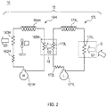
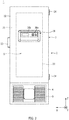
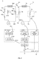
- Second evaporator 175L is affixed onto an outer peripheral surface of an interior body which defines storage space S. Heat of storage space S shifts toward second evaporator 175L by endothermic reaction caused during evaporation of the second refrigerant at second evaporator 175L. As a result, a cooling target within storage space S is cooled.
- First cooling section 6H is a high-temperature side cooling section in a what is known as cascade cycle.
- First compressor 61H, first front stage condenser 62H, first rear stage condenser 63H, first expander 64H, and first evaporator 65H are connected in an annular shape in such a manner as to achieve fluid communication with one another in this order to cause a flow of first refrigerant in first fluid circuit 66H of first cooling section 6H.
- First evaporator 65H further constitutes cascade condenser 8 in cooperation with second rear stage condenser 73L described below. More specifically, cascade condenser 8 is constituted by first evaporator 65H and second rear stage condenser 73L integrated with each other to achieve heat exchange, and cools the second refrigerant at second rear stage condenser 73L by utilizing endothermic reaction caused during evaporation of the first refrigerant by first evaporator 65H.
- Cascade condenser 8 configured as above is constituted by any one of a receiver, a double tube, and a plate type heat exchanger, for example.
- Second cooling section 7L is a low-temperature side cooling section in a what is known as cascade cycle.
- Second compressor 71L, second front stage condenser 72L, second rear stage condenser 73L, second expander 74L, and second evaporator 75L are connected in an annular shape in such a manner as to achieve fluid communication with one another in this order to cause a flow of the second refrigerant, which has a lower boiling point than a boiling point of the first refrigerant, in second fluid circuit 76L of second cooling section 7L.
- Second front stage condenser 72L which has configuration and function similar to the configuration and function of the first front stage condenser, condenses discharge refrigerant received from second compressor 71L, and discharges middle-temperature and high-pressure refrigerant.
- second front stage condenser 72L which is a supplemental condenser for cooling the second refrigerant on the upstream side with respect to cascade condenser 8, may be eliminated.
- two or more second front stage condensers 72L may be provided.
- second rear stage condenser 73L constituting cascade condenser 8 in cooperation with first evaporator 65H further cools discharge refrigerant from second front stage condenser 72L by utilizing endothermic reaction of the first refrigerant caused at first evaporator 65H, and discharges middle-temperature and high-pressure refrigerant.
- Second expander 74L having configuration and function similar to configuration and function of first expander 64H expands and depressurizes the middle-temperature and high-pressure second refrigerant discharged from second rear stage condenser 73L, and discharges the low-temperature and low-pressure second refrigerant.
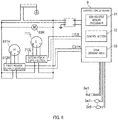
- first temperature sensor Se1 is provided inside storage space S, and configured to detect a temperature of storage space S as an internal temperature, and output a signal indicating detection value PV of the internal temperature (hereinafter abbreviated as detection value PV of internal temperature) to control circuit board 9.
- second temperature sensor Se2 is provided at a position surrounding refrigeration apparatus 1 (e.g., vent hole (not shown) of fan 67H), and configured to detect an ambient temperature, and output a signal indicating a detection value of the ambient temperature (hereinafter abbreviated as detection value ST of ambient temperature) to control circuit board 9.
- detection value ST of ambient temperature a detection value of the ambient temperature
- second temperature sensor Se2 may be further attached to a surface of exterior body 21 in a manner not affected by first rear stage condenser 63H (e.g., inside or surface of control panel 36) to detect an ambient temperature.
- third temperature sensor Se3 is easily attachable, and less affected by the outside temperature. This configuration therefore produces such an advantage that the temperature of the second refrigerant is accurately detectable.
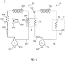
- fourth temperature sensor Se4 is attached to a refrigerant inlet side or refrigerant outlet side of first evaporator 65H in first fluid circuit 66H, for example, and is configured to detect a temperature of the first refrigerant, and output a signal indicating a detection value of the first refrigerant temperature (hereinafter abbreviated as detection value of first refrigerant temperature) to control circuit board 9.
- detection value of first refrigerant temperature hereinafter abbreviated as detection value of first refrigerant temperature
- FIG. 5 illustrates an example of fourth temperature sensor Se4 attached to the refrigerant inlet side.
- third temperature sensor Se3 and fourth temperature sensor Se4 may be attached to various positions other than the positions described above. Examples of other positions include following positions:
- fifth temperature sensor Se5 and sixth temperature sensor Se6 are attached to shell surfaces of first compressor 61H and second compressor 71L, respectively, and configured to output signals indicating detection values correlated to temperatures of first compressor 61H and second compressor 71L (hereinafter abbreviated as detection value of first compressor temperature and detection value of second compressor temperature) to control circuit board 9.
- detection value of first compressor temperature and detection value of second compressor temperature correlated to temperatures of first compressor 61H and second compressor 71L
- fifth temperature sensor Se5 and sixth temperature sensor Se6 may be attached to insides of the shells of first compressor 61H and second compressor 71L.
- control section 92 determines such rotation speeds of first motor 611H and second motor 711L at which deviation e between detection value PV and a target temperature of the internal temperature becomes substantially zero. Thereafter, control section 92 generates first control signal CS1H and second control signal CS2L indicating frequencies correlated with the rotation speed of first motor 611H and the rotation speed of second motor 711L, respectively. Control section 92 outputs first control signal CS1H and second control signal CS2L thus generated to first power supply section 612H and second power supply section 712L, respectively.
- Each of first power supply section 612H and second power supply section 712L is an inverter circuit.
- First power supply section 612H changes a frequency of three-phase alternating current voltage based on input first control signal CS1H, and supplies the changed voltage to first motor 611H. Accordingly, first motor 611H rotates at a rotation speed proportional to the frequency of first control signal CS1 (i.e., rotation speed determined by control section 92).
- Second power supply section 712L changes a frequency of three-phase alternating current voltage based on input second control signal CS2L, and supplies the changed voltage to second motor 711L. Accordingly, second motor 711L rotates at a rotation speed proportional to the frequency of second control signal CS2 (i.e., rotation speed determined by control section 92).
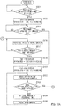
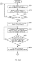
- Example 1 of the internal temperature control is now described with reference to FIGS. 7A and 7B .
- present refrigeration apparatus 1 includes keyboard 36a through which target value SV of the internal temperature is set.
- control section 92 acquires target value SV of the internal temperature set by the user from keyboard 36a, and writes the acquired target value SV to a storage area reserved in non-volatile memory 91 or others in parallel with the processes shown in FIGS. 7A and 7B .
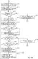
- control section 92 acquires target value SV of the internal temperature from non-volatile memory 91 or others, and acquires detection value PV of the internal temperature from first temperature sensor Se1. Thereafter, control section 92 adds a predetermined temperature to target value SV of the internal temperature to obtain first reference value Vref1 as an example of a temperature reference value (step S007 in FIG. 7B ).
- the predetermined temperature in step S007 is a positive value of approximately +4°C, for example.
- control section 92 determines whether or not detection value PV of the internal temperature is lower than or equal to first reference value Vref1 obtained in step S007 (step S008). When determination is YES in this step, control section 92 performs feedback control based on target value SV and detection value PV of the internal temperature. More specifically, control section 92 initially obtains deviation e between detection value PV and target value SV of the internal temperature (step S009). Subsequently, control section 92 performs PI control (proportional-integral control) which brings deviation e close to zero to calculate target rotation speed B of second compressor 71L. However, maximum rotation speed Bmax has been set for second motor 711L, wherefore an upper limit of target rotation speed B is set to maximum rotation speed Bmax (step S010).
- PI control proportional-integral control
- target rotation speed B is calculated by PI control in a preferable mode according to the present embodiment.
- Target rotation speed B is thus calculated for following reasons.
- P control proportional control
- deviation e may remain for a long period depending on the outside air temperature.
- PI control which performs integral control (I control) using an integrated value of deviation e as well as P control, is executed.
- control section 92 preferably executes proportional-integral-derivative control (PID control) which performs derivative control (D control) using a change with time of deviation e as well as the PI control.
- PID control proportional-integral-derivative control
- Each of heat quantities Q2 and Q3 is determined by heat quantity Q1. Accordingly, once target rotation speed B of second compressor 71L is determined based on heat quantity Q1 (i.e., deviation e) generated by disturbance, target rotation speed A at which first compressor 61H is operated to return the internal temperature to target value SV can be obtained beforehand based on determined target rotation speed B through experiments or the like carried out in a design development stage of present refrigeration apparatus 1.
- target rotation speeds A and B exhibit a predetermined correspondence relation with each other. More specifically, it has been clarified that there is a positive correlation between target rotation speeds A and B (i.e., such relation that one increases as the other increases).
- first cooling section 6H and second cooling section 7L operate most efficiently when target rotation speed A is a value of target rotation speed B multiplied by predetermined coefficient k (k: value ranging from 0.25 to 4.00 (inclusive)) (i.e., when target rotation speed A is proportional to target rotation speed B) in a specific embodiment.
- control section 92 multiplies target rotation speed B determined in step S010 by predetermined coefficient k after completion of step S010 to calculate target rotation speed A proportional to target rotation speed B (step S011).
- control section 92 determines whether or not target rotation speed A calculated in step S011 exceeds maximum rotation speed Amax of first motor 611H (step S012). When determination is YES in this step, control section 92 sets target rotation speed A to maximum rotation speed Amax (step S013).
- control section 92 determines whether or not either one of target rotation speeds A and B obtained in step S013 or earlier is lower than minimum rotation speeds Amin and Bmin of motors 611H and 711L, respectively (steps S014A and S014B). When determination is YES in either one of steps S014A and S014B, one of motors 611H and 711L does not appropriately operates. In this case, control section 92 generates first control signal CS1H and second control signal CS2L to temporarily stop both motors 611H and 711L in consideration that the internal temperature is difficult to return to target value SV. When control signals CS1H and CS2L are supplied to power supply sections 612H and 712L, motors 611H and 711L stop (step S015).
- control section 92 When determination is NO in both the steps, control section 92 generates first control signal CS1H and second control signal CS2L for operating motors 611H and 711L at target rotation speeds A and B, respectively.
- control signals CS1H and CS2L are supplied to power supply sections 612H and 712L, motors 611H and 711L soon come to operate at target rotation speeds A and B (step S019).
- control section 92 preferably changes a rotation speed of motor 68H for fan 67H in accordance with target rotation speed A or target rotation speed B in this step.
- control section 92 when determination is NO in step S008, control section 92 generates first control signal CS1H and second control signal CS2L for operating first motor 611H and second motor 711L at maximum rotation speeds Amax and Bmax, respectively, based on a state that deviation e between detection value PV and target value SV of the internal temperature is still large.
- first control signal CS1H and second control signal CS2L thus generated are supplied to first power supply section 612H and second power supply section 712L, respectively, first motor 611H and second motor 711L soon come to operate at maximum rotation speeds Amax and Bmax (step S021). Thereafter, control section 92 again executes step S008 after completion of step S020.
- control section 92 operates compressors 61H and 71L at maximum rotation speeds Amax and Bmax, respectively, while detection value PV of the internal temperature exceeds first reference value Vref1 (i.e., while determination is NO in step S008) (step S021 in FIG. 7B ). Accordingly, even when the temperature inside storage space S is raised in response to opening of inner door 24 or for other reasons, the internal temperature can rapidly reach a temperature slightly higher than target value SV of the internal temperature (first reference value Vref1) (see period from time t1 to time t2 in FIG. 8 ).
- control section 92 determines target rotation speeds A and B (steps S010 and S011 in FIG. 7B ).
- compressors 61H and 71L are operated at target rotation speeds A and B, respectively (step S019).
- target rotation speed B is determined by PI control based on deviation e between detection value PV and target value SV of the internal temperature, while target rotation speed A is set to a value corresponding to target rotation speed B determined by PI control.
- target rotation speed A is calculated by multiplying target rotation speed B by predetermined coefficient k.
- target rotation speeds A and B are determined by the single feedback system as illustrated in FIG. 9 after detection value PV of the internal temperature reaches first reference value Vref1.
- target rotation speed A is determined based on target rotation speed B calculated by PI control regardless of the temperature of cascade condenser 8.
- first compressor 61H is operated without effects such as heat transmission delay and interference described in column 1-2. Detection value PV of the internal temperature therefore is not excessively reduced to a temperature lower than target value SV (see time t2 and later in FIG. 8 ). Accordingly, efficient operations of compressors 61H and 71L are achievable without producing a waste of energy by present refrigeration apparatus 1.
- target rotation speed A is obtained by multiplying target rotation speed B by coefficient k.
- control section 92 may read target rotation speed A corresponding to target rotation speed B obtained in step S010 from the table, and designate read target rotation speed A as target rotation speed A to be set in step S011.
- column 2-8 is applicable to internal temperature control (Example 2 to Example 5) described below.
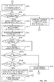
- Example 2 of the internal temperature control is now described with reference to FIGS. 10A and 10B .
- Flows in FIGS. 10A and 10B are different from flows in FIGS. 7A and 7B in that steps S101 to S105 are included instead of steps S004 to S006. No further difference is present between both the flowcharts. Accordingly, steps in FIGS. 10A and 10B similar to corresponding steps in FIGS. 7A and 7B are given identical step numbers, and the same detailed description is not repeated herein.
- control section 92 starts second motor 711L (i.e., second compressor 71L) to rotate second motor 711L at target rotation speed B0 in a manner similar to the manner of step S006 described above (step S101).
- second motor 711L i.e., second compressor 71L
- a time elapsed for a predetermined length from the start of first compressor 61H (delay time) in step S003 in FIG. 10A i.e., a time until a start of second compressor 71L in step S101 after the start of first compressor 61H may be determined in accordance with the second refrigerant temperature or an elapsed time from a stop of second compressor 71L.
- the delay time is reduced in accordance with a detection value acquired by third temperature sensor Se3 as the second refrigerant temperature when the acquired detection value is lower than or equal to -20°C with an elapsed time shorter than two hours from the stop of second compressor 71L, for example.
- the delay time is set to one minute.
- the delay time is prolonged.
- the delay time is set to eight minutes.
- step S101 when the second refrigerant temperature is a temperature lower than a predetermined value, or when an elapsed time from the stop of second compressor 71L is not longer than a predetermined time, the time until the start of second compressor 71L is reduced in step S101.
- the time until the start of second compressor 71L from the start of first compressor 61H does not become excessively long in the state that the second refrigerant temperature is lower than the predetermined value, and that a long time is not elapsed yet after the stop of second compressor 71L. Accordingly, the internal temperature control is more efficiently achievable.
- control section 92 acquires a detection value of the second refrigerant temperature from third temperature sensor Se3 (step S102), and determines whether or not the acquired detection value of the second refrigerant temperature is lower than or equal to a second target temperature determined beforehand (step S103).
- control section 92 executes step S007 and following steps (described above) in FIG. 10B .
- control section 92 stops operation of second compressor 71L for a fixed period to stop high-load operation of second cooling section 7L, and then restarts second compressor 71L (steps S104 and S105). Thereafter, control section 92 again executes step S102 to recheck the second refrigerant temperature.
- the foregoing heat quantity change status is detectable earlier than a temperature change of the first refrigerant based on detection of the temperature of the second refrigerant, as in the manner of the internal temperature control (Example 2). Accordingly, the internal temperature control is more accurately achievable.
- control section 92 stops second compressor 71L for the fixed period, and then restarts second compressor 71L in steps S104 and S105.
- control section 92 may set the rotation speed of first compressor 61H to a speed higher than target rotation speed A0 set in step S002, rather than performing steps S104 and S105. In this manner, a high-load state of second cooling section 7L immediately after power activation is avoidable.
- control section 92 may start second compressor 71L in step S101 in FIG. 10A , acquire a detection value of the second refrigerant temperature from third temperature sensor Se3 in step S102, and then stop second compressor 71L in accordance with the second refrigerant temperature after an elapse of a predetermined time from the start of second compressor 71L.
- second compressor 71L may be stopped in accordance with a detection value acquired as the second refrigerant temperature by third temperature sensor Se3, such as a value higher than or equal to -10°C, after an elapse of 30 seconds as the predetermined time from the start of second compressor 71L.
- a detection value acquired as the second refrigerant temperature by third temperature sensor Se3 such as a value higher than or equal to -10°C, after an elapse of 30 seconds as the predetermined time from the start of second compressor 71L.
- second compressor 71L is not operated in a state that the second refrigerant temperature is higher than the predetermined temperature. Accordingly, a high-load state of second cooling section 7L immediately after power activation is avoidable.
- the predetermined time from the start of second compressor 71L in this case may be changed in accordance with conditions.
- These conditions include such a condition that the second refrigerant temperature higher than a predetermined value is lowering.
- the predetermined time after the start of second compressor 71L is set to a period longer than the corresponding predetermined time in other situations.
- the predetermined time from the start of second compressor 71L is set to 120 seconds.
- Second compressor 71L is restarted in response to confirmation that a predetermined time (first predetermined time) has elapsed after the stop of the second refrigerant by the foregoing steps, and that the temperature of the second refrigerant is lower than a predetermined value, or in response to an elapse of a maximum predetermined time longer than the foregoing first predetermined time.
- control section 92 After power activation, control section 92 initially acquires target value SV of the internal temperature from non-volatile memory 91 or others, and also acquires detection value PV of the internal temperature from first temperature sensor Se1 (see step S201 in FIG. 11A ). Subsequently, control section 92 obtains deviation e between detection value PV and target value SV of the internal temperature thus acquired, and stores deviation e in SRAM 93 or others (step S202).
- control section 92 determines whether or not current deviation e is lower than or equal to third reference value Vref3 obtained in step S210 (step S211).
- control section 92 acquires detection value PV of the internal temperature from first temperature sensor Se1, obtains and updates deviation e based on acquired detection value PV and target value SV (step S213), and then again executes step S211.
- control section 92 calculates target rotation speed B of second compressor 71L in a manner similar to the manners of steps S010 and S011 described above, and then calculates target rotation speed A having a correspondence relation with target rotation speed B (steps S214 and S215).
- control section 92 sets target rotation speed A to maximum rotation speed Amax when calculated target rotation speed A exceeds maximum rotation speed Amax in a manner similar to the manner of steps S012 and S013 described above (steps S216 and S217).
- control section 92 determines whether or not obtained target rotation speed A is lower than minimum rotation speed Amin, and whether or not obtained target rotation speed B is lower than minimum rotation speed Bin, in a manner similar to the manner of steps S014A and S014B after completion of step S217 (steps S218A and S218B).
- step S218A and S218B When determination is YES in either one of steps S218A and S218B, motors 611H and 711L are stopped in a manner similar to the manner of step S015 (step S219). Thereafter, control section 92 again executes step S201 in FIG. 11A .
- control section 92 operates motors 611H and 711L at target rotation speeds A and B, respectively, in a manner similar to the manner of step S019 described above (step S220).
- control section 92 in this step preferably changes a rotation speed of motor 68H for fan 67H in accordance with target rotation speed A in a manner similar to the manner of step S019 described above. Thereafter, control section 92 again executes step S213.
- FIG. 12 Described now with reference to FIG. 12 is an example of changes of rotation speeds of first compressor 61H and second compressor 71L produced when the internal temperature control (Example 3) described above are executed under predetermined conditions.
- detection value PV of the internal temperature is 20°C
- target value SV is -80°C when power is activated for storage space S not cooled at all.
- Deviation e at this time is 100°C.
- step S203 it is determined that current deviation e (100°C) is higher than or equal to second reference value Vref2 in step S203.
- compressors 61H and 71L are started to operate at target rotation speeds A0 and B0, respectively, in step S204.
- the first refrigerant and the second refrigerant start circulating within first fluid circuit 66H and second fluid circuit 76L.
- step S206 When it is determined in step S206 that the second refrigerant temperature is higher than the second target temperature, second compressor 71L is stopped for a predetermined time and restarted in steps S207 and S208 as described above. Alternatively, second compressor 71L may be operated at a low rotation speed for the predetermined time.
- step S206 When it is determined in step S206 that the second refrigerant temperature is lower than or equal to the second target temperature, compressors 61H and 71L are operated at maximum rotation speeds Amax and Bmax, respectively, until determination becomes YES in step S211 as indicated from time t1 to time t2 in FIG. 8 .
- target rotation speed B of second compressor 71L is calculated by PI control shown in step S214 and following steps. Besides, target rotation speed A is calculated by multiplying target rotation speed B by coefficient k.
- target rotation speed A is limited within maximum rotation speed Amax (e.g., 4500 min -1 ) by processing in steps S216 and S217 as indicated by broken line segments connecting (4) and (5) in FIG. 12 .
- refrigeration apparatus 1 When either one of calculated target rotation speeds A and B is lower than minimum rotation speeds Amin and Bmin (e.g., 1500 min -1 ), respectively, refrigeration apparatus 1 does not appropriately operate by operations of compressors 61H and 71L at speeds lower than minimum rotation speeds Amin and Bmin. Accordingly, both compressors 61 H and 71L are stopped at any calculated value of rotation speed B under PI control by processing in steps S218A, S218B, and S219 as indicated by a solid line segment connecting (1) and (2) in FIG. 12 .
- minimum rotation speeds Amin and Bmin e.g. 1500 min -1
- second compressor 71L is operated at target rotation speed B as indicated by a solid straight line connecting (6) and (5) in FIG. 12 .
- FIG. 12 shows an example when k is 1.2.
- Detection value PV of the internal temperature becomes substantially equivalent to target value SV by cyclically repeating the foregoing processing in steps S214 to S218B, S220, and S213 (see time t2 and later in FIG. 8 ).
- both compressors 61H and 71L are stopped in step S219 in FIG. 11B .
- first compressor 61H may be operated at minimum rotation speed Amin.
- first compressor 61H may be only required to operate at a speed lower than a previous speed.
- target rotation speed A is calculated by multiplying target rotation speed B by coefficient k in step S215 in FIG. 11B .
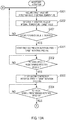
- Example 4 of the internal temperature control is now described with reference to FIGS. 13A and 13B .
- control section 92 When determination is YES in step S203, control section 92 generates first control signal CS1H for operating first compressor 61H at target rotation speed A0 determined beforehand, and supplies generated first control signal CS1H to first power supply section 612H. At this time, target rotation speed A0 is set to 4000 min -1 , for example, to adjust the temperature of cascade condenser 8 to the target temperature as rapidly as possible. In addition, control section 92 generates first control signal CS1H for raising the rotation speed of first motor 611H to target rotation speed A0 based on an acceleration sequence determined beforehand (step S301).
- an actual rotation speed of first compressor 61H is preferably detected by first power supply section 612H constituted by an inverter circuit, and output to control section 92 such that control section 92 can output first control signal CS1H with reference to the actual rotation speed.
- control section 92 is not necessarily required to generate first control signal CS1H based on the actual rotation speed, but may adjust the rotation speed of first compressor 61H to target rotation speed A0 in accordance with the predetermined acceleration sequence as long as a rotation abnormal signal or the like of first compressor 61H is not issued.
- control section 92 When the rotation speed of first compressor 61H reaches target rotation speed A1 (A1: numerical value meeting A1 ⁇ A0) (i.e., after elapse of predetermined time) (step S302), control section 92 subsequently generates second control signal CS2L for operating second compressor 71L at target rotation speed B0 determined beforehand based on an acceleration sequence determined beforehand, and supplies generated second control signal CS2L to second power supply section 712L.
- target rotation speed B0 is set to 2000 min -1 , for example, to adjust the temperature of cascade condenser 8 to an appropriate temperature as rapidly as possible (step S303).
- FIGS. 14A and 14B are different from flows in FIGS. 11A and 11B in that steps S401 to S404 are included instead of steps S204 to S208. No further difference is present between both the flowcharts. Accordingly, steps in FIGS. 14A and 14B similar to corresponding steps in FIGS. 11A and 11B are given identical step numbers, and the same detailed description is not repeated herein.
- control section 92 starts first compressor 61H to operate first compressor 61H at target rotation speed A0 in a manner similar to the manner of step S301 described above (step S401).
- control section 92 acquires a detection value of the second refrigerant temperature from third temperature sensor Se3 (step S402), and determines whether or not the acquired detection value of the second refrigerant temperature is lower than or equal to a second target temperature determined beforehand (step S403).
- a detection value of the first refrigerant temperature may be acquired from fourth temperature sensor Se4, and whether or not the acquired first refrigerant temperature is lower than or equal to the first target temperature may be determined as shown in parentheses in steps S402 and S403 in FIG. 14A , similarly to the description in column 2-15.
- control section 92 again executes step S402.
- control section 92 when determination is YES in step S403, control section 92 generates second control signal CS2L indicating a frequency corresponding to target rotation speed B0 to start second compressor 71L in consideration that a sufficient condition has been achieved for appropriate cooling of the second refrigerant passing through second rear stage condenser 73L, and supplies generated second control signal CS2L to second power supply section 712L.
- second motor 711L i.e., second compressor 71L
- control section 92 executes step S209 and following steps (described above) in FIG. 14B .
- coefficient k may be a fixed value in a preferable range from 0.25 to 4.00 (inclusive).
- a ratio of target rotation speeds A to B i.e., k
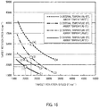
- total power consumption a ratio of target rotation speeds A to B (i.e., k) is preferably varied in accordance with target value SV of the internal temperature and an ambient temperature to minimize total power consumption of both compressors 61H and 71L (hereinafter abbreviated as total power consumption).
- Curve C1 in FIG. 15 represents a correspondence relation between rotation speeds A and B appropriate for obtaining an internal temperature of -70°C under an ambient temperature condition of 15°C.
- a point at which the total power consumption becomes the minimum on curve C1 is point (1) (i.e., target rotation speeds A and B are approximately 1900 min -1 and 2000 min -1 ).
- FIG. 15 also shows curves C2, C3, and C4.
- Curve C2 represents a correspondence relation between rotation speeds A and B for obtaining an internal temperature of -70°C at an ambient temperature of 30°.
- Curves C3 and C4 represent a correspondence relation between rotation speeds A and B for obtaining an internal temperature of -80°C at ambient temperatures of 15°C and 30°C, respectively.
- Points at which the total power consumption becomes the minimum on curves C2, C3, and C4 are points (2), (3), and (4), respectively.
- Points (1) to (4) can be obtained by measuring the total power consumption while appropriately changing the ambient temperature and a value of the internal temperature, and changing the rotation speeds of both compressors 61H and 71L in a design development stage of present refrigeration apparatus 1. According to actual measurements thus obtained, target rotation speeds A and B at point (2) were 2300 min -1 and 2000 min -1 , target rotation speeds A and B at point (3) were 2400 min -1 and 2250 min -1 , and target rotation speeds A and B at point (4) were 3000 min -1 and 2250 min -1 , respectively.
- coefficient k for an ambient temperature of 23°C corresponds to an interpolated value of respective coefficients k for ambient temperatures of 15°C and 30°C in following Table 1.
- Control section 92 retains beforehand a table (Table 1 shown above) which describes optimum coefficient k for each combination of the ambient temperature and the internal temperature (target value).
- control section 92 acquires detection value ST of the ambient temperature from second temperature sensor Se2, and target value SV of the internal temperature stored in non-volatile memory 91 or others, and acquires, from the table, and determines coefficient k corresponding to a combination of detection value ST of the ambient temperature and target value SV of the internal temperature thus acquired (in other words, correspondence relation between rotation speeds A and B).
- control section 92 obtains coefficient k by the interpolation process described above when coefficient k corresponding to detection value ST of the ambient temperature and target value SV of the internal temperature thus acquired is not described in the table.
Landscapes
- Engineering & Computer Science (AREA)
- Physics & Mathematics (AREA)
- Mechanical Engineering (AREA)
- Thermal Sciences (AREA)
- General Engineering & Computer Science (AREA)
- Devices That Are Associated With Refrigeration Equipment (AREA)
Applications Claiming Priority (2)
| Application Number | Priority Date | Filing Date | Title |
|---|---|---|---|
| JP2016028126 | 2016-02-17 | ||
| PCT/JP2017/003835 WO2017141722A1 (ja) | 2016-02-17 | 2017-02-02 | 冷凍装置 |
Publications (3)
| Publication Number | Publication Date |
|---|---|
| EP3401618A1 true EP3401618A1 (de) | 2018-11-14 |
| EP3401618A4 EP3401618A4 (de) | 2019-01-23 |
| EP3401618B1 EP3401618B1 (de) | 2020-04-22 |
Family
ID=59625021
Family Applications (1)
| Application Number | Title | Priority Date | Filing Date |
|---|---|---|---|
| EP17752985.6A Active EP3401618B1 (de) | 2016-02-17 | 2017-02-02 | Kühlvorrichtung |
Country Status (5)
| Country | Link |
|---|---|
| US (1) | US10760825B2 (de) |
| EP (1) | EP3401618B1 (de) |
| JP (1) | JP6603394B2 (de) |
| CN (1) | CN108700350B (de) |
| WO (1) | WO2017141722A1 (de) |
Families Citing this family (10)
| Publication number | Priority date | Publication date | Assignee | Title |
|---|---|---|---|---|
| EP3879205A4 (de) | 2018-11-07 | 2022-08-03 | Shinwa Controls Co., Ltd. | Temperaturanpassungssystem |
| US11566820B2 (en) | 2018-11-07 | 2023-01-31 | Shinwa Controls Co., Ltd. | Fluid temperature control system |
| CN109737566B (zh) * | 2018-12-29 | 2021-09-21 | 青岛海尔空调电子有限公司 | 空调器及其控制方法 |
| CN114198932B (zh) * | 2020-09-17 | 2023-08-11 | 青岛海尔生物医疗股份有限公司 | 一种保存箱控制方法及保存箱 |
| WO2022162723A1 (ja) * | 2021-01-26 | 2022-08-04 | 伸和コントロールズ株式会社 | 流体温調システム |
| US20230019279A1 (en) * | 2021-07-16 | 2023-01-19 | Haier Us Appliance Solutions, Inc. | System and method for operating a variable speed compressor of an air conditioner unit |
| WO2023166907A1 (ja) * | 2022-03-03 | 2023-09-07 | Phcホールディングス株式会社 | 冷凍装置 |
| CN116147258B (zh) * | 2023-03-10 | 2024-09-20 | 海信冰箱有限公司 | 一种冰箱及压缩机控制方法 |
| US20250271190A1 (en) * | 2024-02-23 | 2025-08-28 | Trane Technologies Life Sciences Llc | Compressor control process for variable cascade refrigeration system |
| CN118999031B (zh) * | 2024-10-23 | 2025-03-21 | 浙江蔚盛空调压缩机有限公司 | 一种电动涡旋压缩机调节控制系统 |
Family Cites Families (10)
| Publication number | Priority date | Publication date | Assignee | Title |
|---|---|---|---|---|
| JP3094997B2 (ja) * | 1998-09-30 | 2000-10-03 | ダイキン工業株式会社 | 冷凍装置 |
| US6564568B1 (en) * | 2001-11-14 | 2003-05-20 | Kuei-Hsien Shen | Refrigerating compressor control circuit |
| JP2004190917A (ja) | 2002-12-10 | 2004-07-08 | Sanyo Electric Co Ltd | 冷凍装置 |
| JP5313093B2 (ja) * | 2008-09-16 | 2013-10-09 | パナソニックヘルスケア株式会社 | 冷凍装置 |
| US8011191B2 (en) * | 2009-09-30 | 2011-09-06 | Thermo Fisher Scientific (Asheville) Llc | Refrigeration system having a variable speed compressor |
| CN103250012B (zh) * | 2011-03-18 | 2016-02-17 | 东芝开利株式会社 | 二元制冷循环装置 |
| JP2013011423A (ja) * | 2011-06-30 | 2013-01-17 | Sanyo Electric Co Ltd | 冷凍装置 |
| WO2013035459A1 (ja) * | 2011-09-08 | 2013-03-14 | 株式会社神戸製鋼所 | ヒートポンプ |
| KR101500068B1 (ko) * | 2013-04-02 | 2015-03-06 | 대성히트펌프 주식회사 | 인버터 압축기를 구비한 이원압축 히트펌프 시스템 및 그 이원압축 히트펌프 시스템의 작동방법 및 그 시스템의 인버터 압축기 제어방법 |
| US10024591B2 (en) * | 2014-05-15 | 2018-07-17 | Lennox Industries Inc. | Sensor failure error handling |
-
2017
- 2017-02-02 JP JP2018500032A patent/JP6603394B2/ja active Active
- 2017-02-02 CN CN201780011808.1A patent/CN108700350B/zh active Active
- 2017-02-02 WO PCT/JP2017/003835 patent/WO2017141722A1/ja not_active Ceased
- 2017-02-02 EP EP17752985.6A patent/EP3401618B1/de active Active
-
2018
- 2018-07-27 US US16/048,029 patent/US10760825B2/en active Active
Also Published As
| Publication number | Publication date |
|---|---|
| EP3401618A4 (de) | 2019-01-23 |
| JP6603394B2 (ja) | 2019-11-06 |
| CN108700350B (zh) | 2020-06-16 |
| JPWO2017141722A1 (ja) | 2018-09-13 |
| CN108700350A (zh) | 2018-10-23 |
| EP3401618B1 (de) | 2020-04-22 |
| US20180347863A1 (en) | 2018-12-06 |
| US10760825B2 (en) | 2020-09-01 |
| WO2017141722A1 (ja) | 2017-08-24 |
Similar Documents
| Publication | Publication Date | Title |
|---|---|---|
| EP3401618B1 (de) | Kühlvorrichtung | |
| US8539786B2 (en) | System and method for monitoring overheat of a compressor | |
| JP6500728B2 (ja) | 空調装置 | |
| JP2015016801A5 (de) | ||
| JP2014066410A (ja) | 冷凍サイクル装置 | |
| JP2009063238A (ja) | 冷却貯蔵庫の庫内温度制御装置 | |
| EP2410263A1 (de) | Klimaanlage | |
| JPWO2016136382A1 (ja) | 車両用空調装置 | |
| CN104075415B (zh) | 空调缺氟保护方法和装置 | |
| EP2705255A1 (de) | Überspannungsschutz während der startphase eines kühlkompressors | |
| JP6120808B2 (ja) | 空気調和機 | |
| CN107339780B (zh) | 多联式空调压缩机高低压侧压差的控制方法、装置及空调 | |
| JP2011174639A (ja) | 空気調和機 | |
| JP6459714B2 (ja) | 制御装置及び車両用空調装置 | |
| JP5926154B2 (ja) | 冷蔵庫 | |
| JP2005147584A (ja) | ヒートポンプ給湯装置の起動制御装置および起動制御方法 | |
| JP5619492B2 (ja) | 空気調和装置 | |
| JP6678316B2 (ja) | 冷却装置 | |
| JP2018131023A (ja) | 圧力低下抑制装置 | |
| CN113767257B (zh) | 制冷电器和使噪声冲击最小化的方法 | |
| JP2009174730A (ja) | 冷却装置及びオープンショーケース | |
| AU2023331083A1 (en) | Control device, control method, and air conditioner | |
| JP4425104B2 (ja) | 冷蔵庫 | |
| JP4957767B2 (ja) | 空調装置 | |
| JP4094903B2 (ja) | ポンプ用制御盤 |
Legal Events
| Date | Code | Title | Description |
|---|---|---|---|
| STAA | Information on the status of an ep patent application or granted ep patent |
Free format text: STATUS: THE INTERNATIONAL PUBLICATION HAS BEEN MADE |
|
| PUAI | Public reference made under article 153(3) epc to a published international application that has entered the european phase |
Free format text: ORIGINAL CODE: 0009012 |
|
| STAA | Information on the status of an ep patent application or granted ep patent |
Free format text: STATUS: REQUEST FOR EXAMINATION WAS MADE |
|
| 17P | Request for examination filed |
Effective date: 20180806 |
|
| AK | Designated contracting states |
Kind code of ref document: A1 Designated state(s): AL AT BE BG CH CY CZ DE DK EE ES FI FR GB GR HR HU IE IS IT LI LT LU LV MC MK MT NL NO PL PT RO RS SE SI SK SM TR |
|
| AX | Request for extension of the european patent |
Extension state: BA ME |
|
| A4 | Supplementary search report drawn up and despatched |
Effective date: 20190104 |
|
| RIC1 | Information provided on ipc code assigned before grant |
Ipc: F25B 6/04 20060101ALI20181220BHEP Ipc: F25B 7/00 20060101AFI20181220BHEP Ipc: F25B 49/02 20060101ALI20181220BHEP Ipc: F25B 1/00 20060101ALI20181220BHEP |
|
| DAV | Request for validation of the european patent (deleted) | ||
| DAX | Request for extension of the european patent (deleted) | ||
| GRAJ | Information related to disapproval of communication of intention to grant by the applicant or resumption of examination proceedings by the epo deleted |
Free format text: ORIGINAL CODE: EPIDOSDIGR1 |
|
| STAA | Information on the status of an ep patent application or granted ep patent |
Free format text: STATUS: GRANT OF PATENT IS INTENDED |
|
| GRAP | Despatch of communication of intention to grant a patent |
Free format text: ORIGINAL CODE: EPIDOSNIGR1 |
|
| INTG | Intention to grant announced |
Effective date: 20200107 |
|
| GRAS | Grant fee paid |
Free format text: ORIGINAL CODE: EPIDOSNIGR3 |
|
| GRAA | (expected) grant |
Free format text: ORIGINAL CODE: 0009210 |
|
| STAA | Information on the status of an ep patent application or granted ep patent |
Free format text: STATUS: THE PATENT HAS BEEN GRANTED |
|
| AK | Designated contracting states |
Kind code of ref document: B1 Designated state(s): AL AT BE BG CH CY CZ DE DK EE ES FI FR GB GR HR HU IE IS IT LI LT LU LV MC MK MT NL NO PL PT RO RS SE SI SK SM TR |
|
| REG | Reference to a national code |
Ref country code: CH Ref legal event code: EP |
|
| REG | Reference to a national code |
Ref country code: IE Ref legal event code: FG4D |
|
| REG | Reference to a national code |
Ref country code: DE Ref legal event code: R096 Ref document number: 602017015333 Country of ref document: DE |
|
| REG | Reference to a national code |
Ref country code: AT Ref legal event code: REF Ref document number: 1260649 Country of ref document: AT Kind code of ref document: T Effective date: 20200515 |
|
| REG | Reference to a national code |
Ref country code: NL Ref legal event code: FP |
|
| REG | Reference to a national code |
Ref country code: LT Ref legal event code: MG4D |
|
| PG25 | Lapsed in a contracting state [announced via postgrant information from national office to epo] |
Ref country code: GR Free format text: LAPSE BECAUSE OF FAILURE TO SUBMIT A TRANSLATION OF THE DESCRIPTION OR TO PAY THE FEE WITHIN THE PRESCRIBED TIME-LIMIT Effective date: 20200723 Ref country code: LT Free format text: LAPSE BECAUSE OF FAILURE TO SUBMIT A TRANSLATION OF THE DESCRIPTION OR TO PAY THE FEE WITHIN THE PRESCRIBED TIME-LIMIT Effective date: 20200422 Ref country code: SE Free format text: LAPSE BECAUSE OF FAILURE TO SUBMIT A TRANSLATION OF THE DESCRIPTION OR TO PAY THE FEE WITHIN THE PRESCRIBED TIME-LIMIT Effective date: 20200422 Ref country code: PT Free format text: LAPSE BECAUSE OF FAILURE TO SUBMIT A TRANSLATION OF THE DESCRIPTION OR TO PAY THE FEE WITHIN THE PRESCRIBED TIME-LIMIT Effective date: 20200824 Ref country code: FI Free format text: LAPSE BECAUSE OF FAILURE TO SUBMIT A TRANSLATION OF THE DESCRIPTION OR TO PAY THE FEE WITHIN THE PRESCRIBED TIME-LIMIT Effective date: 20200422 Ref country code: NO Free format text: LAPSE BECAUSE OF FAILURE TO SUBMIT A TRANSLATION OF THE DESCRIPTION OR TO PAY THE FEE WITHIN THE PRESCRIBED TIME-LIMIT Effective date: 20200722 Ref country code: IS Free format text: LAPSE BECAUSE OF FAILURE TO SUBMIT A TRANSLATION OF THE DESCRIPTION OR TO PAY THE FEE WITHIN THE PRESCRIBED TIME-LIMIT Effective date: 20200822 |
|
| REG | Reference to a national code |
Ref country code: AT Ref legal event code: MK05 Ref document number: 1260649 Country of ref document: AT Kind code of ref document: T Effective date: 20200422 |
|
| PG25 | Lapsed in a contracting state [announced via postgrant information from national office to epo] |
Ref country code: HR Free format text: LAPSE BECAUSE OF FAILURE TO SUBMIT A TRANSLATION OF THE DESCRIPTION OR TO PAY THE FEE WITHIN THE PRESCRIBED TIME-LIMIT Effective date: 20200422 Ref country code: LV Free format text: LAPSE BECAUSE OF FAILURE TO SUBMIT A TRANSLATION OF THE DESCRIPTION OR TO PAY THE FEE WITHIN THE PRESCRIBED TIME-LIMIT Effective date: 20200422 Ref country code: RS Free format text: LAPSE BECAUSE OF FAILURE TO SUBMIT A TRANSLATION OF THE DESCRIPTION OR TO PAY THE FEE WITHIN THE PRESCRIBED TIME-LIMIT Effective date: 20200422 Ref country code: BG Free format text: LAPSE BECAUSE OF FAILURE TO SUBMIT A TRANSLATION OF THE DESCRIPTION OR TO PAY THE FEE WITHIN THE PRESCRIBED TIME-LIMIT Effective date: 20200722 |
|
| PG25 | Lapsed in a contracting state [announced via postgrant information from national office to epo] |
Ref country code: AL Free format text: LAPSE BECAUSE OF FAILURE TO SUBMIT A TRANSLATION OF THE DESCRIPTION OR TO PAY THE FEE WITHIN THE PRESCRIBED TIME-LIMIT Effective date: 20200422 |
|
| REG | Reference to a national code |
Ref country code: DE Ref legal event code: R097 Ref document number: 602017015333 Country of ref document: DE |
|
| PG25 | Lapsed in a contracting state [announced via postgrant information from national office to epo] |
Ref country code: CZ Free format text: LAPSE BECAUSE OF FAILURE TO SUBMIT A TRANSLATION OF THE DESCRIPTION OR TO PAY THE FEE WITHIN THE PRESCRIBED TIME-LIMIT Effective date: 20200422 Ref country code: IT Free format text: LAPSE BECAUSE OF FAILURE TO SUBMIT A TRANSLATION OF THE DESCRIPTION OR TO PAY THE FEE WITHIN THE PRESCRIBED TIME-LIMIT Effective date: 20200422 Ref country code: RO Free format text: LAPSE BECAUSE OF FAILURE TO SUBMIT A TRANSLATION OF THE DESCRIPTION OR TO PAY THE FEE WITHIN THE PRESCRIBED TIME-LIMIT Effective date: 20200422 Ref country code: EE Free format text: LAPSE BECAUSE OF FAILURE TO SUBMIT A TRANSLATION OF THE DESCRIPTION OR TO PAY THE FEE WITHIN THE PRESCRIBED TIME-LIMIT Effective date: 20200422 Ref country code: SM Free format text: LAPSE BECAUSE OF FAILURE TO SUBMIT A TRANSLATION OF THE DESCRIPTION OR TO PAY THE FEE WITHIN THE PRESCRIBED TIME-LIMIT Effective date: 20200422 Ref country code: ES Free format text: LAPSE BECAUSE OF FAILURE TO SUBMIT A TRANSLATION OF THE DESCRIPTION OR TO PAY THE FEE WITHIN THE PRESCRIBED TIME-LIMIT Effective date: 20200422 Ref country code: DK Free format text: LAPSE BECAUSE OF FAILURE TO SUBMIT A TRANSLATION OF THE DESCRIPTION OR TO PAY THE FEE WITHIN THE PRESCRIBED TIME-LIMIT Effective date: 20200422 Ref country code: AT Free format text: LAPSE BECAUSE OF FAILURE TO SUBMIT A TRANSLATION OF THE DESCRIPTION OR TO PAY THE FEE WITHIN THE PRESCRIBED TIME-LIMIT Effective date: 20200422 |
|
| PG25 | Lapsed in a contracting state [announced via postgrant information from national office to epo] |
Ref country code: SK Free format text: LAPSE BECAUSE OF FAILURE TO SUBMIT A TRANSLATION OF THE DESCRIPTION OR TO PAY THE FEE WITHIN THE PRESCRIBED TIME-LIMIT Effective date: 20200422 Ref country code: PL Free format text: LAPSE BECAUSE OF FAILURE TO SUBMIT A TRANSLATION OF THE DESCRIPTION OR TO PAY THE FEE WITHIN THE PRESCRIBED TIME-LIMIT Effective date: 20200422 |
|
| PLBE | No opposition filed within time limit |
Free format text: ORIGINAL CODE: 0009261 |
|
| STAA | Information on the status of an ep patent application or granted ep patent |
Free format text: STATUS: NO OPPOSITION FILED WITHIN TIME LIMIT |
|
| 26N | No opposition filed |
Effective date: 20210125 |
|
| PG25 | Lapsed in a contracting state [announced via postgrant information from national office to epo] |
Ref country code: SI Free format text: LAPSE BECAUSE OF FAILURE TO SUBMIT A TRANSLATION OF THE DESCRIPTION OR TO PAY THE FEE WITHIN THE PRESCRIBED TIME-LIMIT Effective date: 20200422 |
|
| PG25 | Lapsed in a contracting state [announced via postgrant information from national office to epo] |
Ref country code: MC Free format text: LAPSE BECAUSE OF FAILURE TO SUBMIT A TRANSLATION OF THE DESCRIPTION OR TO PAY THE FEE WITHIN THE PRESCRIBED TIME-LIMIT Effective date: 20200422 |
|
| REG | Reference to a national code |
Ref country code: BE Ref legal event code: MM Effective date: 20210228 |
|
| PG25 | Lapsed in a contracting state [announced via postgrant information from national office to epo] |
Ref country code: LI Free format text: LAPSE BECAUSE OF NON-PAYMENT OF DUE FEES Effective date: 20210228 Ref country code: LU Free format text: LAPSE BECAUSE OF NON-PAYMENT OF DUE FEES Effective date: 20210202 Ref country code: CH Free format text: LAPSE BECAUSE OF NON-PAYMENT OF DUE FEES Effective date: 20210228 |
|
| PG25 | Lapsed in a contracting state [announced via postgrant information from national office to epo] |
Ref country code: IE Free format text: LAPSE BECAUSE OF NON-PAYMENT OF DUE FEES Effective date: 20210202 |
|
| PG25 | Lapsed in a contracting state [announced via postgrant information from national office to epo] |
Ref country code: BE Free format text: LAPSE BECAUSE OF NON-PAYMENT OF DUE FEES Effective date: 20210228 |
|
| PG25 | Lapsed in a contracting state [announced via postgrant information from national office to epo] |
Ref country code: CY Free format text: LAPSE BECAUSE OF FAILURE TO SUBMIT A TRANSLATION OF THE DESCRIPTION OR TO PAY THE FEE WITHIN THE PRESCRIBED TIME-LIMIT Effective date: 20200422 |
|
| PG25 | Lapsed in a contracting state [announced via postgrant information from national office to epo] |
Ref country code: HU Free format text: LAPSE BECAUSE OF FAILURE TO SUBMIT A TRANSLATION OF THE DESCRIPTION OR TO PAY THE FEE WITHIN THE PRESCRIBED TIME-LIMIT; INVALID AB INITIO Effective date: 20170202 |
|
| PG25 | Lapsed in a contracting state [announced via postgrant information from national office to epo] |
Ref country code: MK Free format text: LAPSE BECAUSE OF FAILURE TO SUBMIT A TRANSLATION OF THE DESCRIPTION OR TO PAY THE FEE WITHIN THE PRESCRIBED TIME-LIMIT Effective date: 20200422 |
|
| PG25 | Lapsed in a contracting state [announced via postgrant information from national office to epo] |
Ref country code: TR Free format text: LAPSE BECAUSE OF FAILURE TO SUBMIT A TRANSLATION OF THE DESCRIPTION OR TO PAY THE FEE WITHIN THE PRESCRIBED TIME-LIMIT Effective date: 20200422 |
|
| PG25 | Lapsed in a contracting state [announced via postgrant information from national office to epo] |
Ref country code: MT Free format text: LAPSE BECAUSE OF FAILURE TO SUBMIT A TRANSLATION OF THE DESCRIPTION OR TO PAY THE FEE WITHIN THE PRESCRIBED TIME-LIMIT Effective date: 20200422 |
|
| PGFP | Annual fee paid to national office [announced via postgrant information from national office to epo] |
Ref country code: NL Payment date: 20260226 Year of fee payment: 10 |
|
| PGFP | Annual fee paid to national office [announced via postgrant information from national office to epo] |
Ref country code: GB Payment date: 20260227 Year of fee payment: 10 |
|
| PGFP | Annual fee paid to national office [announced via postgrant information from national office to epo] |
Ref country code: DE Payment date: 20260227 Year of fee payment: 10 |
|
| PGFP | Annual fee paid to national office [announced via postgrant information from national office to epo] |
Ref country code: FR Payment date: 20260225 Year of fee payment: 10 |