EP3401244B1 - Fördern eines förderguts - Google Patents
Fördern eines förderguts Download PDFInfo
- Publication number
- EP3401244B1 EP3401244B1 EP17170817.5A EP17170817A EP3401244B1 EP 3401244 B1 EP3401244 B1 EP 3401244B1 EP 17170817 A EP17170817 A EP 17170817A EP 3401244 B1 EP3401244 B1 EP 3401244B1
- Authority
- EP
- European Patent Office
- Prior art keywords
- fluid
- system housing
- housing
- pressure
- inlet
- Prior art date
- Legal status (The legal status is an assumption and is not a legal conclusion. Google has not performed a legal analysis and makes no representation as to the accuracy of the status listed.)
- Active
Links
- 239000012530 fluid Substances 0.000 claims description 236
- 239000000463 material Substances 0.000 claims description 26
- 238000000034 method Methods 0.000 claims description 15
- 238000007599 discharging Methods 0.000 claims description 5
- 239000003082 abrasive agent Substances 0.000 claims description 3
- 238000001816 cooling Methods 0.000 claims description 3
- 238000000746 purification Methods 0.000 claims description 2
- 239000007789 gas Substances 0.000 description 25
- 238000007872 degassing Methods 0.000 description 19
- 239000000428 dust Substances 0.000 description 19
- 239000000126 substance Substances 0.000 description 9
- IJGRMHOSHXDMSA-UHFFFAOYSA-N Atomic nitrogen Chemical compound N#N IJGRMHOSHXDMSA-UHFFFAOYSA-N 0.000 description 6
- 238000004140 cleaning Methods 0.000 description 5
- QVGXLLKOCUKJST-UHFFFAOYSA-N atomic oxygen Chemical compound [O] QVGXLLKOCUKJST-UHFFFAOYSA-N 0.000 description 3
- 239000007788 liquid Substances 0.000 description 3
- 239000000203 mixture Substances 0.000 description 3
- 229910052757 nitrogen Inorganic materials 0.000 description 3
- 239000001301 oxygen Substances 0.000 description 3
- 229910052760 oxygen Inorganic materials 0.000 description 3
- 230000001105 regulatory effect Effects 0.000 description 3
- 239000011261 inert gas Substances 0.000 description 2
- 230000002452 interceptive effect Effects 0.000 description 2
- 230000035515 penetration Effects 0.000 description 2
- 238000011144 upstream manufacturing Methods 0.000 description 2
- UGFAIRIUMAVXCW-UHFFFAOYSA-N Carbon monoxide Chemical compound [O+]#[C-] UGFAIRIUMAVXCW-UHFFFAOYSA-N 0.000 description 1
- 230000009286 beneficial effect Effects 0.000 description 1
- 230000001413 cellular effect Effects 0.000 description 1
- 238000006243 chemical reaction Methods 0.000 description 1
- 230000001419 dependent effect Effects 0.000 description 1
- 238000001914 filtration Methods 0.000 description 1
- 239000003546 flue gas Substances 0.000 description 1
- 238000010438 heat treatment Methods 0.000 description 1
- 210000000056 organ Anatomy 0.000 description 1
- 230000003647 oxidation Effects 0.000 description 1
- 238000007254 oxidation reaction Methods 0.000 description 1
- 230000000704 physical effect Effects 0.000 description 1
- 230000001681 protective effect Effects 0.000 description 1
Images


Classifications
-
- B—PERFORMING OPERATIONS; TRANSPORTING
- B65—CONVEYING; PACKING; STORING; HANDLING THIN OR FILAMENTARY MATERIAL
- B65G—TRANSPORT OR STORAGE DEVICES, e.g. CONVEYORS FOR LOADING OR TIPPING, SHOP CONVEYOR SYSTEMS OR PNEUMATIC TUBE CONVEYORS
- B65G21/00—Supporting or protective framework or housings for endless load-carriers or traction elements of belt or chain conveyors
- B65G21/08—Protective roofs or arch supports therefor
-
- B—PERFORMING OPERATIONS; TRANSPORTING
- B65—CONVEYING; PACKING; STORING; HANDLING THIN OR FILAMENTARY MATERIAL
- B65G—TRANSPORT OR STORAGE DEVICES, e.g. CONVEYORS FOR LOADING OR TIPPING, SHOP CONVEYOR SYSTEMS OR PNEUMATIC TUBE CONVEYORS
- B65G69/00—Auxiliary measures taken, or devices used, in connection with loading or unloading
- B65G69/18—Preventing escape of dust
- B65G69/181—Preventing escape of dust by means of sealed systems
- B65G69/182—Preventing escape of dust by means of sealed systems with aspiration means
-
- B—PERFORMING OPERATIONS; TRANSPORTING
- B65—CONVEYING; PACKING; STORING; HANDLING THIN OR FILAMENTARY MATERIAL
- B65G—TRANSPORT OR STORAGE DEVICES, e.g. CONVEYORS FOR LOADING OR TIPPING, SHOP CONVEYOR SYSTEMS OR PNEUMATIC TUBE CONVEYORS
- B65G69/00—Auxiliary measures taken, or devices used, in connection with loading or unloading
- B65G69/20—Auxiliary treatments, e.g. aerating, heating, humidifying, deaerating, cooling, de-watering or drying, during loading or unloading; Loading or unloading in a fluid medium other than air
-
- C—CHEMISTRY; METALLURGY
- C21—METALLURGY OF IRON
- C21B—MANUFACTURE OF IRON OR STEEL
- C21B13/00—Making spongy iron or liquid steel, by direct processes
-
- C—CHEMISTRY; METALLURGY
- C21—METALLURGY OF IRON
- C21C—PROCESSING OF PIG-IRON, e.g. REFINING, MANUFACTURE OF WROUGHT-IRON OR STEEL; TREATMENT IN MOLTEN STATE OF FERROUS ALLOYS
- C21C5/00—Manufacture of carbon-steel, e.g. plain mild steel, medium carbon steel or cast steel or stainless steel
- C21C5/52—Manufacture of steel in electric furnaces
- C21C5/527—Charging of the electric furnace
-
- F—MECHANICAL ENGINEERING; LIGHTING; HEATING; WEAPONS; BLASTING
- F27—FURNACES; KILNS; OVENS; RETORTS
- F27B—FURNACES, KILNS, OVENS, OR RETORTS IN GENERAL; OPEN SINTERING OR LIKE APPARATUS
- F27B9/00—Furnaces through which the charge is moved mechanically, e.g. of tunnel type; Similar furnaces in which the charge moves by gravity
-
- F—MECHANICAL ENGINEERING; LIGHTING; HEATING; WEAPONS; BLASTING
- F27—FURNACES; KILNS; OVENS; RETORTS
- F27D—DETAILS OR ACCESSORIES OF FURNACES, KILNS, OVENS, OR RETORTS, IN SO FAR AS THEY ARE OF KINDS OCCURRING IN MORE THAN ONE KIND OF FURNACE
- F27D15/00—Handling or treating discharged material; Supports or receiving chambers therefor
- F27D15/02—Cooling
-
- F—MECHANICAL ENGINEERING; LIGHTING; HEATING; WEAPONS; BLASTING
- F27—FURNACES; KILNS; OVENS; RETORTS
- F27D—DETAILS OR ACCESSORIES OF FURNACES, KILNS, OVENS, OR RETORTS, IN SO FAR AS THEY ARE OF KINDS OCCURRING IN MORE THAN ONE KIND OF FURNACE
- F27D17/00—Arrangements for using waste heat; Arrangements for using, or disposing of, waste gases
-
- B—PERFORMING OPERATIONS; TRANSPORTING
- B65—CONVEYING; PACKING; STORING; HANDLING THIN OR FILAMENTARY MATERIAL
- B65G—TRANSPORT OR STORAGE DEVICES, e.g. CONVEYORS FOR LOADING OR TIPPING, SHOP CONVEYOR SYSTEMS OR PNEUMATIC TUBE CONVEYORS
- B65G2207/00—Indexing codes relating to constructional details, configuration and additional features of a handling device, e.g. Conveyors
- B65G2207/40—Safety features of loads, equipment or persons
-
- C—CHEMISTRY; METALLURGY
- C21—METALLURGY OF IRON
- C21B—MANUFACTURE OF IRON OR STEEL
- C21B13/00—Making spongy iron or liquid steel, by direct processes
- C21B13/0086—Conditioning, transformation of reduced iron ores
- C21B13/0093—Protecting against oxidation
-
- F—MECHANICAL ENGINEERING; LIGHTING; HEATING; WEAPONS; BLASTING
- F27—FURNACES; KILNS; OVENS; RETORTS
- F27B—FURNACES, KILNS, OVENS, OR RETORTS IN GENERAL; OPEN SINTERING OR LIKE APPARATUS
- F27B3/00—Hearth-type furnaces, e.g. of reverberatory type; Tank furnaces
- F27B3/10—Details, accessories, or equipment peculiar to hearth-type furnaces
- F27B3/18—Arrangements of devices for charging
-
- Y—GENERAL TAGGING OF NEW TECHNOLOGICAL DEVELOPMENTS; GENERAL TAGGING OF CROSS-SECTIONAL TECHNOLOGIES SPANNING OVER SEVERAL SECTIONS OF THE IPC; TECHNICAL SUBJECTS COVERED BY FORMER USPC CROSS-REFERENCE ART COLLECTIONS [XRACs] AND DIGESTS
- Y02—TECHNOLOGIES OR APPLICATIONS FOR MITIGATION OR ADAPTATION AGAINST CLIMATE CHANGE
- Y02P—CLIMATE CHANGE MITIGATION TECHNOLOGIES IN THE PRODUCTION OR PROCESSING OF GOODS
- Y02P10/00—Technologies related to metal processing
- Y02P10/20—Recycling
Definitions
- the invention relates to a method for operating a conveyor system for conveying a reactive and/or hot and/or abrasive material to be conveyed.
- Reactive conveyed material is understood here as conveyed material that can react chemically and/or physically with the substances surrounding the conveyor system, for example with air, in particular with the oxygen in the air. Such reactions are generally undesirable since they can lead, for example, to oxidation of the conveyed material and/or excessive heating of the conveyed material and/or fluid that is harmful to health and/or the environment, for example degassing gas, and/or dust can be released.
- a fluid for example an inert gas such as nitrogen or a gas mixture of nitrogen and a maximum of 3% oxygen or a gas mixture consisting of the chemical components of a flue gas, is often used to remove surrounding substances to displace from the environment of the conveyed.
- a fluid is understood here as a gas or a liquid.
- U.S. 2011/318698 A1 discloses a method according to the preamble of claim 1.
- the invention is based on the object of specifying a conveyor system and a method for conveying a reactive conveyed item which are improved in particular with regard to the consumption of fluid for displacing ambient substances from the environment of the conveyed item.
- the conveyor system of the method comprises a system housing encasing the conveying path, which has at least one fluid inlet for introducing fluid into the system housing, at least one fluid outlet for discharging fluid from the system housing and a charging inlet for introducing conveyed goods into the system housing and, apart from the at least one Fluid inlet, the at least one fluid outlet and the charging inlet is designed to be technically fluid-tight.
- fluid tightness is understood to mean technical fluid tightness.
- the arrangement of the conveying path in a system housing enables the conveying path to be largely encapsulated in relation to its surroundings, so that the conveyed material is largely sealed off from the surrounding substances.
- the largely fluid-tight design of the system housing limits the escape of fluid from the system housing to the fluid outlets, so that only a relatively small amount of fluid escapes from the system housing.
- fluid escaping from the system housing to be collected at least partially in a targeted manner at the fluid outlets and fed back to the system housing.
- the consumption and the costs of the fluid used are advantageously reduced.
- Degassing gas and dust forming in the system housing can also be discharged in a targeted manner at the fluid outlets. This advantageously eliminates the need for separate collection and disposal devices at other points for dust or degassing gas escaping from the system housing.
- the system housing has a discharge opening for discharging conveyed material from the system housing, and that the discharge opening is a fluid outlet or a fluid inlet of the system housing.
- the discharge opening is a fluid outlet or a fluid inlet of the system housing.
- a further embodiment of the invention provides that the dispensing opening can be closed by a shut-off element.
- the shut-off device can have, for example, one or more shut-off slides spaced apart from one another for closing the dispensing opening. In this way, for example, in the event of an emergency shutdown of the conveyor system, fluid and degassing gas can be prevented from escaping from the discharge opening.
- the dispensing opening can be closed in a fluid-tight manner, in particular in the manner of a sluice, by means of a plurality of shut-off slides spaced apart from one another.
- a further embodiment of the invention provides at least one safety element arranged on the system housing, which is used to discharge fluid from the system housing if a fluid pressure in the system housing exceeds a pressure threshold value, or to regulate the fluid pressure in order to keep the fluid pressure within a controlled pressure range. is trained. As a result, an overpressure in the system housing can advantageously be prevented.
- a fluid circuit system which is designed to introduce fluid into the system housing through at least one fluid inlet and to collect and reuse fluid exiting the system housing through at least one fluid outlet.
- the fluid circuit system can in particular have a flow machine for introducing fluid into the system housing.
- a flow machine for introducing fluid into the system housing.
- the fluid circuit system can have a heat exchanger for cooling the fluid and/or a fluid cleaning unit for cleaning fluid exiting the system housing.
- a heat exchanger for cooling the fluid is particularly advantageous in cases in which hot material to be conveyed is being transported in the system housing and components of a conveying mechanism that are to be cooled are arranged for conveying the material to be conveyed.
- the fluid fed into the system housing and cooled by the heat exchanger can advantageously also be used to cool components of the conveying mechanism.
- Fluid drawn off from the system housing can be cleaned by a fluid cleaning unit, for example to remove degassing gas and/or dust that forms in the system housing and is transported with the fluid.
- a further embodiment of the invention provides that the charging inlet can be closed in a fluid-tight manner by a shut-off device. This can prevent fluid and degassing gas from escaping from the charging inlet, for example in the event of an emergency shutdown of the conveyor system.
- a fluid is introduced into the system housing through the at least one fluid inlet introduced and conducted in a fluid flow direction, which is essentially parallel to a conveying direction in which conveyed material is transported through the system housing, through the system housing to the at least one fluid outlet.
- fluid, degassing gas carried with the fluid and/or dust carried with the fluid can be routed in a defined fluid flow direction through the system housing to the fluid outlets and discharged there.
- turbulences in the fluid, degassing gas and dust flows in the system housing can also advantageously be reduced.
- a fluid atmosphere in the system housing is regulated in such a way that it counteracts the penetration of an interfering fluid from a neighboring unit adjacent to the system housing into the system housing.
- a fluid atmosphere in the system housing is understood to mean the chemical and physical properties, for example the chemical composition, the pressure or the temperature, of a fluid that is located in the system housing.
- a disruptive fluid is understood to mean a fluid that is not desired in the system housing.
- Typical interfering fluids are oxygen-containing gases or gases that contain at least one undesired chemical component in too high a concentration, or fluids that are too hot or too cold.
- the control of the fluid atmosphere in the system housing which counteracts the penetration of disruptive fluid into the system housing, prevents in particular that a larger quantity of disruptive fluid enters the system housing due to pressure fluctuations in a neighboring unit and impairs the quality of the conveyed material.
- a fluid pressure in the system housing is regulated to a target value that is greater than a current disturbance fluid pressure in the neighboring unit.
- a differential pressure between the fluid pressure in the system housing and the Störfluiddruck in the neighboring unit detected and a fluid flow introduced into the system housing is regulated as a function of the differential pressure.
- FIG 1 shows schematically an embodiment of a conveyor system 1 for conveying a reactive and/or hot and/or abrasive material to be conveyed along a conveying path.
- the conveyor system 1 has a system housing 3 in which the conveying path is arranged.
- the system housing 3 has a Charging inlet 4 for introducing conveyed material into the system housing, a fluid inlet 5 for introducing fluid into the system housing 3 and two fluid outlets 7, 9 for dispensing fluid from the system housing 3.
- a first fluid outlet 7 is a discharge opening for discharging conveyed material from the system housing 3.
- the system housing 3 is designed to be fluid-tight except for at least the fluid inlet 5, the fluid outlets 7, 9 and the charging inlet 4.
- the conveyor system 1 has a fluid circuit system 11 which is designed to introduce fluid into the system housing and to collect and reuse fluid drawn off from the system housing 3 .
- the fluid introduced into the system housing 3 is, for example, an inert gas such as nitrogen, but can alternatively also be a liquid.
- the fluid circuit system 11 introduces fluid through the fluid inlet 5 into the system housing 3 , through the system housing 3 and through the second fluid outlet 9 out of the system housing 3 . Furthermore, the fluid circuit system 11 directs the fluid exiting the system housing 3 through the second fluid outlet 9 via a turbomachine 13 and optionally via a heat exchanger 15 and/or a fluid cleaning unit 17 through the fluid inlet 5 back into the system housing 3 . Furthermore, the fluid circuit system 11 has a fluid feed 19 , through which fluid can be supplied to the fluid circuit system 11 , in particular to replace fluid that emerges from the system housing 3 through the first fluid outlet 7 .
- the flow machine 13 is, for example, a blower or a compressor or another pressure boosting unit or a pump, depending on whether the fluid is a gas or a liquid.
- the fluid is introduced into the system housing 3 by the turbomachine 13 at a pressure that is greater than a pressure in the system housing 3, so that fluid flows through the fluid inlet 5 enters the system housing 3, but does not exit from the system housing 3.
- the fluid inlet 5 is arranged in the vicinity of the charging inlet 4 .
- the second fluid outlet 9 is arranged in the vicinity of the first fluid outlet 7 .
- the fluid is guided through the system housing 3 to the fluid outlets 7, 9 in a fluid flow direction 30, which is essentially parallel to a conveying direction 32 in which the material to be conveyed is transported through the system housing 3.
- degassing gas that is also produced in the system housing 3 in a degassing flow direction 34, which is essentially parallel to a conveying direction 32, and dust that forms in the system housing 3 in a dust flow direction 36, which is essentially parallel to a conveying direction 32, passed through the system housing 3 to the fluid outlets 7, 9.
- the fluid inlet 5 and/or the second fluid outlet 9 can also be located at locations other than those in figure 1 shown locations of the system housing 3 arranged, for example opposite figure 1 interchanged, to be.
- fluid could also be fed to a unit downstream or upstream of the conveyor system 1 , for example a bunker, and fed back from this unit to the system housing 3 via the fluid circuit system 11 , so that the unit becomes part of the fluid circuit system 11 .
- dust can also be discharged from the system housing 3 into the downstream or upstream unit or disposed of thereby.
- a dedusting device can optionally be provided at the charging inlet 4, wherein more fluid is supplied via the fluid supply 19 than is discharged from the system housing 3 by the dedusting device.
- the optional heat exchanger 15 is used to cool the fluid. He is particularly beneficial in cases where in the System housing 3 is transported a hot conveyed and to be cooled components of a conveyor mechanism 23 are arranged to promote the conveyed. In these cases, the fluid fed into the system housing 3 and cooled by the heat exchanger 15 can advantageously also be used to cool components of the conveying mechanism 23 .
- the fluid drawn off from the system housing 3 can be cleaned by the optional fluid cleaning unit 17 , for example to remove degassing gas and/or dust that forms in the system housing 3 and is transported by the fluid.
- the largely fluid-tight design of the system housing 3 limits the escape of fluid from the system housing 3 to the fluid outlets 7 , 9 , so that only a relatively small amount of fluid escapes from the system housing 3 . Furthermore, fluid discharged from the second fluid outlet 9 is fed back to the system housing 3 through the fluid circuit system 11 via the first fluid inlet 5 , so that this fluid remains in the fluid circuit system 11 . Overall, the amount of fluid to be supplied to the fluid circuit system 11 can be kept relatively small. This advantageously reduces fluid consumption and fluid costs.
- the fluid flows flowing through the first fluid inlet 5 and the second fluid outlet 9 are substantially larger than the fluid flow flowing through the first fluid outlet 7 .
- the fluid flow through the first fluid inlet 5 can be about 1600 m 3 /h
- the fluid flow through the second fluid outlet 9 can be about 1500 m 3 /h
- the fluid flow through the first fluid outlet 7 can be about 100 m 3 /h, where the About 100 m 3 /h of fluid are supplied to the fluid circuit system 11 via the fluid supply 19 in order to replace the fluid flowing off through the first fluid outlet 7 .
- Another advantage of the largely fluid-tight design of the system housing 3 and the fluid flow direction 30 is that degassing gas and dust can also be routed to the fluid outlets 7, 9 and disposed of there.
- a safety element 21 designed as a safety valve is arranged on the system housing 3 and is designed to discharge fluid from the system housing 3 when a fluid pressure in the system housing 3 exceeds a pressure threshold value.
- figure 2 shows a schematic sectional view of the conveyor system 1 in the area of the first fluid outlet 7, which is also the discharge opening of the system housing 3.
- the material to be conveyed is transported by the conveying mechanism 23 to the first fluid outlet 7 and discharged there downwards through the fluid outlet 7 .
- Fluid, degassing gas and dust are also discharged from the fluid outlet 7 with the conveyed material. Since degassing gas and dust are discharged with the conveyed material from the fluid outlet 7, they can be discharged and disposed of together with the conveyed material. This advantageously eliminates the need for separate collection and disposal devices at other points for dust or degassing gas escaping from the system housing 3 .
- the first fluid outlet 7 can also be closed by a shut-off device 40 .
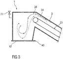
- FIG 3 shows a sectional view of the conveyor system 1 in the area of the first fluid outlet 7, which is closed by a shut-off element 40.
- the shut-off device 40 has, for example, a gate valve 42 for closing the first fluid outlet 7 on. This can prevent fluid and degassing gas from escaping from the first fluid outlet 7 in the event of an emergency shutdown of the conveyor system 1, for example. Accordingly, the charging inlet 4 can also be closed in a fluid-tight manner by a shut-off element 40 .
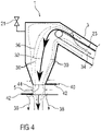
- figure 4 shows a schematic sectional view of a second exemplary embodiment of a conveyor system 1 in the area of a discharge opening for the discharge of conveyed goods.
- This embodiment differs from that in FIGS Figures 1 to 3 illustrated embodiment, inter alia, characterized in that the output opening is a fluid inlet 5 for introducing fluid into the system housing 3.
- the fluid and the degassing gas flow essentially in parallel, but differently figure 2 at least along a section of the conveying path opposite to a conveying direction 32 of the conveyed material and a dust flow direction 36 of dust within the system housing 3.
- shut-off device 40 has two spaced-apart shut-off slides 42 and an auxiliary unit 44 is arranged between the shut-off slides 42 .
- the auxiliary unit 44 is, for example, a cellular wheel sluice for discharging conveyed material from the system housing 3.
- figure 5 shows a schematic sectional view of a third exemplary embodiment of a conveyor system 1 in the area of a discharge opening for the discharge of conveyed goods.
- This embodiment differs from that in figure 4 illustrated embodiment in that fluid flows both through the dispensing opening and through another (in figure 5 not shown) fluid inlet 5 is conducted into the system housing 3, wherein the fluid flow direction 30 of the fluid introduced through the discharge opening into the system housing 3 is at least along a partial section of the conveying path substantially is opposite to a conveying direction 32 of the conveyed goods and the fluid flow direction 30 of the fluid conducted through the further fluid inlet 5 into the system housing 3 essentially corresponds to the conveying direction 32 .
- system housing 3 has a fluid outlet 9 through which fluid is discharged from the system housing 3 and downstream of which a filter system 46 for filtering fine dust and a vacuum generator 48 for sucking fluid out of the system housing 3 are connected.
- Fluid that is discharged through the fluid outlet 9 from the system housing 3 is, for example, either disposed of or reused at least in part by a fluid circuit system 11 analogous to figure 1 the system housing 3 is fed back.
Landscapes
- Engineering & Computer Science (AREA)
- Mechanical Engineering (AREA)
- Chemical & Material Sciences (AREA)
- General Engineering & Computer Science (AREA)
- Manufacturing & Machinery (AREA)
- Materials Engineering (AREA)
- Metallurgy (AREA)
- Organic Chemistry (AREA)
- Environmental & Geological Engineering (AREA)
- Air Transport Of Granular Materials (AREA)
- Intermediate Stations On Conveyors (AREA)
- Cleaning In General (AREA)
- Furnace Details (AREA)
- Chain Conveyers (AREA)
- Container, Conveyance, Adherence, Positioning, Of Wafer (AREA)
- Commercial Cooking Devices (AREA)
- Physical Or Chemical Processes And Apparatus (AREA)
- Structures Of Non-Positive Displacement Pumps (AREA)
- Supplying Of Containers To The Packaging Station (AREA)
- Control And Other Processes For Unpacking Of Materials (AREA)
- Filling Or Emptying Of Bunkers, Hoppers, And Tanks (AREA)
Description
- Die Erfindung betrifft ein Verfahren zum Betrieb einer Förderanlage zum Fördern eines reaktiven und/oder heißen und/oder abrasiven Förderguts.
- Unter einem reaktiven Fördergut wird hier ein Fördergut verstanden, das chemisch oder/und physikalisch mit die Förderanlage umgebenden Umgebungsstoffen, beispielsweise mit Luft, insbesondere mit dem Sauerstoff der Luft, reagieren kann. Derartige Reaktionen sind in der Regel unerwünscht, da sie beispielsweise zur Oxidation des Förderguts und/oder zur übermäßigen Erhitzung des Förderguts führen können und/oder gesundheitsschädliches und/oder umweltschädliches Fluid, beispielsweise Entgasungsgas, und/oder Staub freisetzen können. Um den Kontakt eines Förderguts mit Umgebungsstoffen zu vermeiden oder zu reduzieren, wird oft ein Fluid, beispielsweise ein Inertgas wie Stickstoff oder ein Gasgemisch aus Stickstoff und maximal 3% Sauerstoff oder ein Gasgemisch, das aus den chemischen Komponenten eines Rauchgases besteht, eingesetzt, um Umgebungsstoffe aus der Umgebung des Förderguts zu verdrängen. Unter einem Fluid wird hier ein Gas oder eine Flüssigkeit verstanden.
-
US 2011/318698 A1 offenbart ein Verfahren nach dem Oberbegriff des Anspruchs 1. - Der Erfindung liegt die Aufgabe zugrunde, eine Förderanlage und ein Verfahren zum Fördern eines reaktiven Förderguts anzugeben, die insbesondere hinsichtlich des Verbrauchs an Fluid zur Verdrängung von Umgebungsstoffen aus der Umgebung des Förderguts verbessert sind.
- Die Aufgabe wird erfindungsgemäß durch ein Verfahren nach Anspruch 1 gelöst.
- Vorteilhafte Ausgestaltungen der Erfindung sind Gegenstand der Unteransprüche.
- Die Förderanlage des Verfahrens umfasst ein den Förderweg umhüllendes Anlagengehäuse, das wenigstens einen Fluideinlass zur Einleitung von Fluid in das Anlagengehäuse, wenigstens einen Fluidauslass zur Ausgabe von Fluid aus dem Anlagengehäuse und einen Chargiereinlass zum Einbringen von Fördergut in das Anlagengehäuse aufweist und bis auf den wenigstens einen Fluideinlass, den wenigstens einen Fluidauslass und den Chargiereinlass technisch fluiddicht ausgeführt ist.
- Im Folgenden wird unter Fluiddichtheit jeweils technische Fluiddichtheit verstanden.
- Die Anordnung des Förderwegs in einem Anlagengehäuse ermöglicht eine weitgehende Kapselung des Förderwegs gegenüber dessen Umgebung, so dass das Fördergut gegenüber Umgebungsstoffen weitgehend abgeschottet ist. Durch die weitgehend fluiddichte Ausführung des Anlagengehäuses wird ein Austreten von Fluid aus dem Anlagengehäuse auf die Fluidauslässe begrenzt, so dass nur eine relativ geringe Menge von Fluid aus dem Anlagengehäuse entweicht. Ferner ermöglicht sie, aus dem Anlagengehäuse austretendes Fluid gezielt an den Fluidauslässen wenigstens teilweise aufzufangen und dem Anlagengehäuse wieder zuzuführen. Dadurch werden der Verbrauch und die Kosten des eingesetzten Fluids vorteilhaft reduziert. Auch Entgasungsgas und sich in dem Anlagengehäuse bildender Staub können gezielt an den Fluidauslässen abgeführt werden. Dadurch entfallen vorteilhaft separate Auffang- und Entsorgungsvorrichtungen an anderen Stellen für aus dem Anlagengehäuse austretenden Staub oder austretendes Entgasungsgas.
- Erfindungsgemäß wird es vorgesehen, dass das Anlagengehäuse eine Ausgabeöffnung zur Ausgabe von Fördergut aus dem Anlagengehäuse aufweist, und dass die Ausgabeöffnung ein Fluidauslass oder ein Fluideinlass des Anlagengehäuses ist. Dadurch kann Fluid durch die ohnehin vorhandene Ausgabeöffnung des Anlagengehäuses ab- oder eingeführt werden. Ferner wird vorteilhaft eine Fluidströmungsrichtung, in der das Fluid durch das Anlagengehäuse strömt, einer Förderrichtung angeglichen, in der das Fördergut zu der Ausgabeöffnung transportiert wird. Des Weiteren können Turbulenzen in dem Fluidstrom vorteilhaft reduziert werden.
- Eine weitere Ausgestaltung der Erfindung sieht vor, dass die Ausgabeöffnung durch ein Absperrorgan verschließbar ist. Das Absperrorgan kann beispielsweise einen oder mehrere voneinander beabstandete Absperrschieber zum Verschließen der Ausgabeöffnung aufweisen. Dadurch kann beispielsweise im Falle einer Notabschaltung der Förderanlage ein Austreten von Fluid und Entgasungsgas aus der Ausgabeöffnung verhindert werden. Durch mehrere voneinander beabstandete Absperrschieber kann die Ausgabeöffnung insbesondere schleusenartig fluiddicht verschlossen werden.
- Eine weitere Ausgestaltung der Erfindung sieht wenigstens ein an dem Anlagengehäuse angeordnetes Sicherheitsorgan vor, das zum Auslass von Fluid aus dem Anlagengehäuse, wenn ein Fluiddruck in dem Anlagengehäuse einen Druckschwellenwert überschreitet, oder zur Regelung des Fluiddrucks, um den Fluiddruck in einem kontrollierten Druckbereich zu halten, ausgebildet ist. Dadurch kann vorteilhaft ein Überdruck in dem Anlagengehäuse verhindert werden.
- Erfindungsgemäß wird ein Fluidkreislaufsystem vorgesehen, welches zum Einleiten von Fluid in das Anlagengehäuse durch wenigstens einen Fluideinlass und zum Auffangen und Wiederverwenden von durch wenigstens einen Fluidauslass aus dem Anlagengehäuse austretendem Fluid ausgebildet ist. Durch ein derartiges Fluidkreislaufsystem kann vorteilhaft der Verbrauch von Fluid weiter gesenkt werden, da aus dem Anlagengehäuse Fluid abgezogen und über das Fluidkreislaufsystem dem Anlagengehäuse wieder zugeführt wird, so dass dieses Fluid in dem Fluidkreislaufsystem verbleibt.
- Das Fluidkreislaufsystem kann insbesondere eine Strömungsmaschine zum Einleiten von Fluid in das Anlagengehäuse aufweisen. Dadurch kann vorteilhaft die Fluidströmungsrichtung des Fluids in das Anlagengehäuse hinein und durch das Anlagengehäuse hindurch beeinflusst werden.
- Ferner kann das Fluidkreislaufsystem einen Wärmetauscher zur Kühlung des Fluids oder/und eine Fluidreinigungseinheit zur Reinigung aus dem Anlagengehäuse austretenden Fluids aufweisen. Ein Wärmetauscher zur Kühlung des Fluids ist besonders in Fällen vorteilhaft, in denen in dem Anlagengehäuse ein heißes Fördergut transportiert wird und zu kühlende Komponenten einer Fördermechanik zur Förderung des Förderguts angeordnet sind. In diesen Fällen kann das in das Anlagengehäuse geleitete und durch den Wärmetauscher abgekühlte Fluid vorteilhaft auch zur Kühlung von Komponenten der Fördermechanik eingesetzt werden. Durch eine Fluidreinigungseinheit kann aus dem Anlagengehäuse abgezogenes Fluid gereinigt werden, beispielsweise von Entgasungsgas und/oder von Staub, die sich in dem Anlagengehäuse bilden und mit dem Fluid transportiert werden. Eine weitere Ausgestaltung der Erfindung sieht vor, dass der Chargiereinlass durch ein Absperrorgan fluiddicht verschließbar ist. Dadurch kann beispielsweise im Falle einer Notabschaltung der Förderanlage ein Austreten von Fluid und Entgasungsgas aus dem Chargiereinlass verhindert werden.
- Erfindungsgemäß wird ein Fluid durch den wenigstens einen Fluideinlass in das Anlagengehäuse eingeleitet und in einer Fluidströmungsrichtung, die im Wesentlichen parallel zu einer Förderrichtung ist, in der Fördergut durch das Anlagengehäuse transportiert wird, durch das Anlagengehäuse zu dem wenigstens einen Fluidauslass geleitet. Dadurch können Fluid, mit dem Fluid geführtes Entgasungsgas und/oder mit dem Fluid geführter Staub in einer definierten Fluidströmungsrichtung durch das Anlagengehäuse zu den Fluidauslässen geleitet und dort abgeführt werden. Ferner können überdies vorteilhaft Turbulenzen der Fluid-, Entgasungsgas- und Staubströmungen in dem Anlagengehäuse reduziert werden.
- Erfindungsgemäß wird es vorgesehen, dass eine Fluidatmosphäre in dem Anlagengehäuse derart geregelt wird, dass sie einem Eindringen von einem Störfluid aus einem dem Anlagengehäuse benachbarten Nachbaraggregat in das Anlagengehäuse entgegenwirkt. Unter einer Fluidatmosphäre in dem Anlagengehäuse werden die chemischen und physikalischen Eigenschaften, beispielsweise die chemische Zusammensetzung, der Druck oder die Temperatur, eines Fluids verstanden, das sich in dem Anlagengehäuse befindet. Unter einem Störfluid wird ein in dem Anlagengehäuse nicht erwünschtes Fluid verstanden. Typische Störfluide sind sauerstoffhaltige Gase oder Gase, die mindestens eine unerwünschte chemische Komponente in zu hoher Konzentration enthalten, oder Fluide, die zu heiß oder zu kalt sind. Die einem Eindringen von Störfluid in das Anlagengehäuse entgegenwirkende Regelung der Fluidatmosphäre in dem Anlagengehäuse verhindert insbesondere, dass durch Druckschwankungen in einem Nachbaraggregat eine größere Störfluidmenge in das Anlagengehäuse gelangt und die Qualität des Förderguts beeinträchtigt.
- Erfindungsgemäß wird ein Fluiddruck in dem Anlagengehäuse auf einen Sollwert geregelt, der größer als ein momentaner Störfluiddruck in dem Nachbaraggregat ist. Beispielsweise wird dabei ein Differenzdruck zwischen dem Fluiddruck in dem Anlagengehäuse und dem Störfluiddruck in dem Nachbaraggregat erfasst und ein in das Anlagengehäuse eingeleiteter Fluidstrom wird in Abhängigkeit von dem Differenzdruck geregelt.
- Die oben beschriebenen Eigenschaften, Merkmale und Vorteile dieser Erfindung sowie die Art und Weise, wie diese erreicht werden, werden klarer und deutlicher verständlich im Zusammenhang mit der folgenden Beschreibung von Ausführungsbeispielen, die im Zusammenhang mit den Zeichnungen näher erläutert werden. Dabei zeigen:
-
FIG 1 schematisch ein erstes Ausführungsbeispiel einer Förderanlage, -
FIG 2 schematisch eine Schnittdarstellung der inFigur 1 dargestellten Förderanlage im Bereich einer Ausgabeöffnung zur Ausgabe von Fördergut aus dem Anlagengehäuse bei geöffneter Ausgabeöffnung, -
FIG 3 schematisch eine Schnittdarstellung der inFigur 2 gezeigten Förderanlage bei geschlossener Ausgabeöffnung, -
FIG 4 schematisch eine Schnittdarstellung eines zweiten Ausführungsbeispiels einer Förderanlage im Bereich einer Ausgabeöffnung zur Ausgabe von Fördergut, und -
FIG 5 schematisch eine Schnittdarstellung eines dritten Ausführungsbeispiels einer Förderanlage im Bereich einer Ausgabeöffnung zur Ausgabe von Fördergut. - Einander entsprechende Teile sind in den Figuren mit denselben Bezugszeichen versehen.
-
Figur 1 zeigt schematisch ein Ausführungsbeispiel einer Förderanlage 1 zum Fördern eines reaktiven und/oder heißen und/oder abrasiven Förderguts entlang eines Förderwegs. Die Förderanlage 1 weist ein Anlagengehäuse 3 auf, in der der Förderweg angeordnet ist. Das Anlagengehäuse 3 weist einen Chargiereinlass 4 zum Einbringen von Fördergut in das Anlagengehäuse, einen Fluideinlass 5 zur Einleitung von Fluid in das Anlagengehäuse 3 und zwei Fluidauslässe 7, 9 zur Ausgabe von Fluid aus dem Anlagengehäuse 3 auf. Ein erster Fluidauslass 7 ist eine Ausgabeöffnung zur Ausgabe von Fördergut aus dem Anlagengehäuse 3. Das Anlagengehäuse 3 ist bis auf den wenigstens den Fluideinlass 5, die Fluidauslässe 7, 9 und den Chargiereinlass 4 fluiddicht ausgeführt. - Ferner weist die Förderanlage 1 ein Fluidkreislaufsystem 11 auf, welches zum Einleiten von Fluid in das Anlagengehäuse und zum Auffangen und Wiederverwenden von aus dem Anlagengehäuse 3 abgezogenen Fluid ausgebildet ist. Das in das Anlagengehäuse 3 eingeleitete Fluid ist beispielsweise ein Inertgas wie Stickstoff, kann aber alternativ auch eine Flüssigkeit sein.
- Das Fluidkreislaufsystem 11 leitet Fluid durch den Fluideinlass 5 in das Anlagengehäuse 3 ein, durch das Anlagengehäuse 3 hindurch und durch den zweiten Fluidauslass 9 aus dem Anlagengehäuse 3 heraus. Ferner leitet das Fluidkreislaufsystem 11 das durch den zweiten Fluidauslass 9 aus dem Anlagengehäuse 3 austretende Fluid über eine Strömungsmaschine 13 und optional über einen Wärmetauscher 15 und/oder eine Fluidreinigungseinheit 17 durch den Fluideinlass 5 wieder in das Anlagengehäuse 3 ein. Ferner weist das Fluidkreislaufsystem 11 eine Fluidzuführung 19 auf, durch die dem Fluidkreislaufsystem 11 Fluid zuführbar ist, insbesondere um Fluid zu ersetzen, das aus dem Anlagengehäuse 3 durch den ersten Fluidauslass 7 austritt. Die Strömungsmaschine 13 ist beispielsweise ein Gebläse oder ein Kompressor oder ein anderes Druckerhöhungsaggregat oder eine Pumpe, je nachdem, ob das Fluid ein Gas oder eine Flüssigkeit ist. Durch die Strömungsmaschine 13 wird das Fluid mit einem Druck in das Anlagengehäuse 3 eingeleitet, der größer als ein Druck in dem Anlagengehäuse 3 ist, so dass Fluid durch den Fluideinlass 5 in das Anlagengehäuse 3 eintritt, aber nicht aus dem Anlagengehäuse 3 austritt. Der Fluideinlass 5 ist bei diesem Ausführungsbeispiel in der Nähe des Chargiereinlasses 4 angeordnet. Der zweite Fluidauslass 9 ist in der Nähe des ersten Fluidauslasses 7 angeordnet. Dadurch wird das Fluid in einer Fluidströmungsrichtung 30, die im Wesentlichen parallel zu einer Förderrichtung 32, in der Fördergut durch das Anlagengehäuse 3 transportiert wird, durch das Anlagengehäuse 3 zu den Fluidauslässen 7, 9 geleitet. Ferner werden mit dem Fluid auch in dem Anlagengehäuse 3 entstehendes Entgasungsgas in einer Entgasungsströmungsrichtung 34, die im Wesentlichen parallel zu einer Förderrichtung 32 ist, und sich in dem Anlagengehäuse 3 bildender Staub in einer Staubströmungsrichtung 36, die im Wesentlichen parallel zu einer Förderrichtung 32 ist, durch das Anlagengehäuse 3 zu den Fluidauslässen 7, 9 geleitet. Bei anderen Ausführungsbeispielen können der Fluideinlass 5 und/oder der zweite Fluidauslass 9 auch an anderen Stellen als an den in
Figur 1 gezeigten Stellen des Anlagengehäuses 3 angeordnet, beispielsweise gegenüberFigur 1 miteinander vertauscht, sein. Alternativ könnte Fluid auch einem der Förderanlage 1 nachgeschalteten oder vorgeschalteten Aggregat, beispielsweise einem Bunker, zugeführt und aus diesem Aggregat dem Anlagengehäuse 3 über das Fluidkreislaufsystem 11 wieder zugeführt werden, so dass das Aggregat Teil des Fluidkreislaufsystems 11 wird. In diesem Fall kann vorteilhaft mit dem Fluid auch Staub aus dem Anlagengehäuse 3 in das nach- oder vorgeschaltete Aggregat abgeführt beziehungsweise dadurch entsorgt werden. Ferner kann optional am Chargiereinlass 4 eine Entstaubungsvorrichtung vorgesehen sein, wobei über die Fluidzuführung 19 mehr Fluid zugeführt wird als durch die Entstaubungsvorrichtung aus dem Anlagengehäuse 3 abgeführt wird. - Der optionale Wärmetauscher 15 dient der Kühlung des Fluids. Er ist besonders in Fällen vorteilhaft, in denen in dem Anlagengehäuse 3 ein heißes Fördergut transportiert wird und zu kühlende Komponenten einer Fördermechanik 23 zur Förderung des Förderguts angeordnet sind. In diesen Fällen kann das in das Anlagengehäuse 3 geleitete und durch den Wärmetauscher 15 abgekühlte Fluid vorteilhaft auch zur Kühlung von Komponenten der Fördermechanik 23 eingesetzt werden. Durch die optionale Fluidreinigungseinheit 17 kann aus dem Anlagengehäuse 3 abgezogenes Fluid gereinigt werden, beispielsweise von Entgasungsgas und/oder von Staub, die sich in dem Anlagengehäuse 3 bilden und von dem Fluid transportiert werden.
- Durch die weitgehend fluiddichte Ausführung des Anlagengehäuses 3 wird ein Austreten von Fluid aus dem Anlagengehäuse 3 auf die Fluidauslässe 7, 9 begrenzt, so dass nur eine relativ geringe Menge von Fluid aus dem Anlagengehäuse 3 entweicht. Ferner wird dem Anlagengehäuse 3 aus dem zweiten Fluidauslass 9 abgeführtes Fluid durch das Fluidkreislaufsystem 11 über den ersten Fluideinlass 5 wieder zugeführt, so dass dieses Fluid in dem Fluidkreislaufsystem 11 verbleibt. Insgesamt kann dadurch die dem Fluidkreislaufsystem 11 zuzuführende Menge von Fluid relativ gering gehalten werden. Dadurch werden der Verbrauch von Fluid und die Kosten für das Fluid vorteilhaft reduziert.
- Typischerweise sind die durch den ersten Fluideinlass 5 und den zweiten Fluidauslass 9 fließenden Fluidströme wesentlich größer als der durch den ersten Fluidauslass 7 fließende Fluidstrom. Beispielsweise können der durch den ersten Fluideinlass 5 fließende Fluidstrom etwa 1600 m3/h, der durch den zweiten Fluidauslass 9 fließenden Fluidstrom etwa 1500 m3/h und der durch den ersten Fluidauslass 7 fließende Fluidstrom etwa 100 m3/h betragen, wobei dem Fluidkreislaufsystem 11 über die Fluidzuführung 19 etwa 100 m3/h Fluid zugeführt werden, um das durch den ersten Fluidauslass 7 abfließende Fluid zu ersetzen.
- Ein weiterer Vorteil der weitgehend fluiddichten Ausführung des Anlagengehäuses 3 und der Fluidströmungsrichtung 30 ist, dass Entgasungsgas und Staub ebenfalls zu den Fluidauslässen 7, 9 geleitet und dort entsorgt werden können.
- An dem Anlagengehäuse 3 ist ein als ein Sicherheitsventil ausgebildetes Sicherheitsorgan 21 angeordnet, das zum Auslass von Fluid aus dem Anlagengehäuse 3 ausgebildet ist, wenn ein Fluiddruck in dem Anlagengehäuse 3 einen Druckschwellenwert überschreitet.
-
Figur 2 zeigt schematisch eine Schnittdarstellung der Förderanlage 1 im Bereich des ersten Fluidauslasses 7, der gleichzeitig die Ausgabeöffnung des Anlagengehäuses 3 ist. Das Fördergut wird von der Fördermechanik 23 zu dem ersten Fluidauslass 7 transportiert und dort nach unten durch den Fluidauslass 7 ausgegeben. Mit dem Fördergut werden auch Fluid, Entgasungsgas und Staub aus dem Fluidauslass 7 ausgegeben. Da Entgasungsgas und Staub mit dem Fördergut aus dem Fluidauslass 7 ausgegeben werden, können sie mit dem Fördergut zusammen abgeführt und entsorgt werden. Dadurch entfallen vorteilhaft separate Auffang- und Entsorgungsvorrichtungen an anderen Stellen für aus dem Anlagengehäuse 3 austretenden Staub oder austretendes Entgasungsgas. - Optional kann vorgesehen sein, den Fluidauslass 7 mit einem Gasschleier 38 zu umströmen, der die aus dem Fluidauslass 7 austretende Materie (Fördergut, Fluid, Entgasungsgas, Staub) umhüllt.
- Die erste Fluidauslass 7 kann ferner durch ein Absperrorgan 40 verschließbar sein.
-
Figur 3 zeigt eine Schnittdarstellung der Förderanlage 1 im Bereich des ersten Fluidauslasses 7, der durch ein Absperrorgan 40 verschlossen ist. Das Absperrorgan 40 weist beispielsweise einen Absperrschieber 42 zum Verschließen des ersten Fluidauslasses 7 auf. Dadurch kann beispielsweise im Falle einer Notabschaltung der Förderanlage 1 ein Austreten von Fluid und Entgasungsgas aus dem ersten Fluidauslass 7 verhindert werden. Entsprechend kann auch der Chargiereinlass 4 durch ein Absperrorgan 40 fluiddicht verschließbar sein. -
Figur 4 zeigt schematisch eine Schnittdarstellung eines zweiten Ausführungsbeispiels einer Förderanlage 1 im Bereich einer Ausgabeöffnung zur Ausgabe von Fördergut. Dieses Ausführungsbeispiel unterscheidet sich von dem in denFiguren 1 bis 3 dargestellten Ausführungsbeispiel unter anderem dadurch, dass die Ausgabeöffnung ein Fluideinlass 5 zum Einleiten von Fluid in das Anlagengehäuse 3 ist. Das Fluid und das Entgasungsgas strömen im Wesentlichen parallel, aber im Unterschied zuFigur 2 zumindest entlang eines Teilabschnitts des Förderwegs entgegensetzt zu einer Förderrichtung 32 des Förderguts und einer Staubströmungsrichtung 36 von Staub innerhalb des Anlagengehäuses 3. Ein weiterer Unterschied zu der in denFiguren 1 bis 3 dargestellten Förderanlage 1 ist, dass das Absperrorgan 40 zwei voneinander beabstandete Absperrschieber 42 aufweist und zwischen den Absperrschiebern 42 ein Hilfsaggregat 44 angeordnet ist. Das Hilfsaggregat 44 ist beispielsweise eine Zellenradschleuse zum Ausschleusen von Fördergut aus dem Anlagengehäuse 3. -
Figur 5 zeigt schematisch eine Schnittdarstellung eines dritten Ausführungsbeispiels einer Förderanlage 1 im Bereich einer Ausgabeöffnung zur Ausgabe von Fördergut. Dieses Ausführungsbeispiel unterscheidet sich von dem inFigur 4 dargestellten Ausführungsbeispiel dadurch, dass Fluid sowohl durch die Ausgabeöffnung als auch durch einen weiteren (inFigur 5 nicht dargestellten) Fluideinlass 5 in das Anlagengehäuse 3 geleitet wird, wobei die Fluidströmungsrichtung 30 des durch die Ausgabeöffnung in das Anlagengehäuse 3 eingeleitenden Fluids zumindest entlang eines Teilabschnitts des Förderwegs im Wesentlichen entgegensetzt zu einer Förderrichtung 32 des Förderguts ist und die Fluidströmungsrichtung 30 des durch den weiteren Fluideinlass 5 in das Anlagengehäuse 3 geleiteten Fluids im Wesentlichen mit der Förderrichtung 32 übereinstimmt. Außerdem weist das Anlagengehäuse 3 einen Fluidauslass 9 auf, durch den Fluid aus dem Anlagengehäuse 3 abgeführt wird und dem ein Filtersystem 46 zur Filterung von Feinstaub und ein Unterdruckerzeuger 48 zum Ansaugen von Fluid aus dem Anlagengehäuse 3 nachgeschaltet sind. Fluid, das durch den Fluidauslass 9 aus dem Anlagengehäuse 3 abgeführt wird, wird beispielsweise entweder entsorgt oder wenigstens zu einem Teil wiederverwendet, indem es über ein Fluidkreislaufsystem 11 analog zuFigur 1 dem Anlagengehäuse 3 wieder zugeführt wird. - Obwohl die Erfindung im Detail durch bevorzugte Ausführungsbeispiele näher illustriert und beschrieben wurde, so ist die Erfindung nicht durch die offenbarten Beispiele eingeschränkt und andere Variationen können vom Fachmann hieraus abgeleitet werden, ohne den Schutzumfang der Ansprüche zu verlassen.
-
- 1
- Förderanlage
- 3
- Anlagengehäuse
- 4
- Chargiereinlass
- 5
- Fluideinlass
- 7, 9
- Fluidauslass
- 11
- Fluidkreislaufsystem
- 13
- Strömungsmaschine
- 15
- Wärmetauscher
- 17
- Fluidreinigungseinheit
- 19
- Fluidzuführung
- 21
- Sicherheitsorgan
- 23
- Fördermechanik
- 30
- Fluidströmungsrichtung
- 32
- Förderrichtung
- 34
- Entgasungsströmungsrichtung
- 36
- Staubströmungsrichtung
- 38
- Gasschleier
- 40
- Absperrorgan
- 42
- Absperrschieber
- 44
- Hilfsaggregat
- 46
- Filtersystem
- 48
- Unterdruckerzeuger
Claims (10)
- Verfahren zum Betrieb einer Förderanlage (1) zum kontinuierlichen oder diskontinuierlichen Fördern eines reaktiven und/oder heißen und/oder abrasiven Förderguts entlang eines Förderwegs, die Förderanlage (1) umfassend ein den Förderweg umhüllendes Anlagengehäuse (3), das wenigstens einen Fluideinlass (5) zur Einleitung von Fluid in das Anlagengehäuse (3), wenigstens einen Fluidauslass (7, 9) zur Ausgabe von Fluid aus dem Anlagengehäuse (3), einen Chargiereinlass (4) zum Einbringen von Fördergut in das Anlagengehäuse (3) und eine Ausgabeöffnung zur Ausgabe von Fördergut aus dem Anlagengehäuse (3)aufweist und bis auf den wenigstens einen Fluideinlass (5), den wenigstens einen Fluidauslass (7, 9) und den Chargiereinlass (4) technisch fluiddicht ausgeführt ist,wobei die Ausgabeöffnung ein Fluidauslass (7,9) oder ein Fluideinlass (5) des Anlagengehäuses (3) ist,wobei ein Fluid durch den wenigstens einen Fluideinlass (5) in das Anlagengehäuse (3) eingeleitet und in einer Fluidströmungsrichtung (30), die im Wesentlichen parallel zu einer Förderrichtung (32) ist, in der Fördergut durch das Anlagengehäuse (3) transportiert wird, durch das Anlagengehäuse (3) zu dem wenigstens einen Fluidauslass (7, 9) geleitet wirdund eine Fluidatmosphäre in dem Anlagengehäuse (3) derart geregelt wird, dass sie einem Eindringen von einem Störfluid aus einem dem Anlagengehäuse (3) benachbarten Nachbaraggregat in das Anlagengehäuse (3) entgegenwirkt,wobei ein Fluiddruck in dem Anlagengehäuse (3) auf einen Sollwert geregelt wird, der größer als ein momentaner Störfluiddruck in dem Nachbaraggregat ist,dadurch gekennzeichnet, dassdie Förderanlage (1) ein Fluidkreislaufsystem (11) aufweist, mit welchem Fluid in das Anlagengehäuse (3) durch wenigstens einen Fluideinlass (5) eingeleitet wird und durch wenigstens einen Fluidauslass (7, 9) aus dem Anlagengehäuse (3) austretendes Fluid aufgefangen und wiederverwendet wird.
- Verfahren nach Anspruch 1,
wobei die Förderanlage ein Absperrorgan (40) aufweist, durch das die Ausgabeöffnung verschließbar ist. - Verfahren nach Anspruch 2,
wobei das Absperrorgan (40) wenigstens einen Absperrschieber (42) zum Verschließen der Ausgabeöffnung aufweist. - Verfahren nach Anspruch 3,
wobei das Absperrorgan (40) zwei voneinander beabstandete Absperrschieber (42) zum Verschließen der Ausgabeöffnung aufweist. - Verfahren nach einem der vorhergehenden Ansprüche,
wobei die Förderanlage (1) wenigstens ein an dem Anlagengehäuse (3) angeordnetes Sicherheitsorgan (21) aufweist, das zum Auslass von Fluid aus dem Anlagengehäuse (3), wenn ein Fluiddruck in dem Anlagengehäuse (3) einen Druckschwellenwert überschreitet, oder zur Regelung des Fluiddrucks, um den Fluiddruck in einem kontrollierten Druckbereich zu halten, ausgebildet ist. - Verfahren nach einem der vorhergehenden Ansprüche,
wobei das Fluidkreislaufsystem (11) eine Strömungsmaschine (13) zum Einleiten von Fluid in das Anlagengehäuse (3) aufweist. - Verfahren nach einem der vorhergehenden Ansprüche,
wobei das Fluidkreislaufsystem (11) wenigstens einen Wärmetauscher (15) zur Kühlung des Fluids aufweist. - Verfahren nach einem der vorhergehenden Ansprüche ,
wobei das Fluidkreislaufsystem (11) eine Fluidreinigungseinheit (17) zur Reinigung aus dem Anlagengehäuse (3) austretenden Fluids aufweist. - Verfahren nach einem der vorhergehenden Ansprüche,
wobei die Förderanlage (1) ein Absperrorgan (40) aufweist, durch das der Chargiereinlass (4)fluiddicht verschließbar ist. - Verfahren nach einem der vorhergehenden Ansprüche,
wobei ein Differenzdruck zwischen dem Fluiddruck in dem Anlagengehäuse (3) und dem Störfluiddruck in dem Nachbaraggregat erfasst wird und ein in das Anlagengehäuse (3) eingeleiteter Fluidstrom in Abhängigkeit von dem Differenzdruck geregelt wird.
Priority Applications (11)
| Application Number | Priority Date | Filing Date | Title |
|---|---|---|---|
| EP17170817.5A EP3401244B1 (de) | 2017-05-12 | 2017-05-12 | Fördern eines förderguts |
| ES17170817T ES2937938T3 (es) | 2017-05-12 | 2017-05-12 | Transporte de un artículo por transportar |
| PL17170817.5T PL3401244T3 (pl) | 2017-05-12 | 2017-05-12 | Transportowanie materiału transportowanego |
| RS20230031A RS63891B1 (sr) | 2017-05-12 | 2017-05-12 | Transportovanje transportovanog materijala |
| RU2019135691A RU2758919C2 (ru) | 2017-05-12 | 2018-05-03 | Транспортирование транспортируемого материала |
| CA3065631A CA3065631A1 (en) | 2017-05-12 | 2018-05-03 | Conveying a material to be conveyed |
| MX2019013430A MX2019013430A (es) | 2017-05-12 | 2018-05-03 | Transporte de un material a transportar. |
| PCT/EP2018/061309 WO2018206384A1 (de) | 2017-05-12 | 2018-05-03 | Fördern eines förderguts |
| US16/612,912 US10947050B2 (en) | 2017-05-12 | 2018-05-03 | Conveying a material to be conveyed |
| TW107115453A TWI754054B (zh) | 2017-05-12 | 2018-05-07 | 輸送系統及用於操作輸送系統的方法 |
| SA519410492A SA519410492B1 (ar) | 2017-05-12 | 2019-11-05 | نقل مادة يُراد نقلها |
Applications Claiming Priority (1)
| Application Number | Priority Date | Filing Date | Title |
|---|---|---|---|
| EP17170817.5A EP3401244B1 (de) | 2017-05-12 | 2017-05-12 | Fördern eines förderguts |
Publications (2)
| Publication Number | Publication Date |
|---|---|
| EP3401244A1 EP3401244A1 (de) | 2018-11-14 |
| EP3401244B1 true EP3401244B1 (de) | 2022-11-09 |
Family
ID=58707387
Family Applications (1)
| Application Number | Title | Priority Date | Filing Date |
|---|---|---|---|
| EP17170817.5A Active EP3401244B1 (de) | 2017-05-12 | 2017-05-12 | Fördern eines förderguts |
Country Status (11)
| Country | Link |
|---|---|
| US (1) | US10947050B2 (de) |
| EP (1) | EP3401244B1 (de) |
| CA (1) | CA3065631A1 (de) |
| ES (1) | ES2937938T3 (de) |
| MX (1) | MX2019013430A (de) |
| PL (1) | PL3401244T3 (de) |
| RS (1) | RS63891B1 (de) |
| RU (1) | RU2758919C2 (de) |
| SA (1) | SA519410492B1 (de) |
| TW (1) | TWI754054B (de) |
| WO (1) | WO2018206384A1 (de) |
Families Citing this family (2)
| Publication number | Priority date | Publication date | Assignee | Title |
|---|---|---|---|---|
| ES2927909T3 (es) * | 2017-05-12 | 2022-11-11 | Primetals Technologies Austria GmbH | Transporte de un material para transportar |
| EP3766809A1 (de) * | 2019-07-15 | 2021-01-20 | Primetals Technologies Austria GmbH | Fördern eines förderguts |
Family Cites Families (18)
| Publication number | Priority date | Publication date | Assignee | Title |
|---|---|---|---|---|
| US3036440A (en) * | 1960-02-03 | 1962-05-29 | United States Steel Corp | Method of cooling briquettes of iron particles |
| US3096627A (en) * | 1960-07-14 | 1963-07-09 | Liquefreeze Company Inc | Apparatus for quick freezing of bakery goods |
| SU939347A1 (ru) * | 1980-12-31 | 1982-06-30 | Новочеркасский ордена Трудового Красного Знамени политехнический институт им. Серго Орджоникидзе | Устройство обеспыливани пунктов перегрузки материала на ленточных конвейерах |
| GB8425716D0 (en) | 1984-10-11 | 1984-11-14 | Quantum Laser Uk Ltd | Screw powder feeders |
| GB0004845D0 (en) * | 2000-02-29 | 2000-04-19 | Tetronics Ltd | A method and apparatus for packaging ultra fine powders into containers |
| KR20040042020A (ko) * | 2002-11-12 | 2004-05-20 | 이상만 | 부상식 벨트콘베이어 장치 |
| DE20302678U1 (de) * | 2003-02-19 | 2003-05-22 | AUMUND-Fördererbau GmbH & Co. KG, 47495 Rheinberg | Heißgutförderer |
| US7316728B2 (en) * | 2003-05-28 | 2008-01-08 | Entegris, Inc. | Method and apparatus for treating fluids |
| DE202006015233U1 (de) | 2006-10-02 | 2007-02-22 | BÄ*RO GmbH & Co KG | Transporteinrichtung für Lebensmittel |
| US20080251356A1 (en) * | 2007-04-13 | 2008-10-16 | Peter Bratusa | System for particulate removal and reclamation in a manufacturing environment |
| DE102009048321A1 (de) | 2009-10-05 | 2011-04-07 | Messer Group Gmbh | Vorrichtung und Verfahren zum Pelletieren oder Granulieren eines flüssigen oder pastösen Stoffes |
| US20110318698A1 (en) * | 2010-06-28 | 2011-12-29 | Siddhartha Gaur | Zero water discharge oven cooling |
| CN201842461U (zh) * | 2010-09-30 | 2011-05-25 | 山东建设机械股份有限公司 | 全密封皮带输送机 |
| ITVR20110095A1 (it) * | 2011-05-06 | 2012-11-07 | Agricola Rofin S R L Soc | Impianto per la produzione di biogas. |
| TWM415136U (en) * | 2011-06-10 | 2011-11-01 | Fande Ind Co Ltd | Feeding and anti-fouling equipment with improved transmission |
| RU161397U1 (ru) * | 2015-12-23 | 2016-04-20 | Федеральное государственное бюджетное образовательное учреждение высшего профессионального образования "Белгородский государственный технологический университет им. В.Г. Шухова" | Аспирационное укрытие мест перегрузки сыпучего материала |
| US10036314B2 (en) * | 2016-01-11 | 2018-07-31 | Caterpillar Inc. | Fuel system flush circuitry and method for operating the same |
| PL3478612T3 (pl) * | 2016-07-04 | 2021-09-27 | Frieslandcampina Nederland B.V. | Zespół rozdzielacza dla pneumatycznego systemu transportowego |
-
2017
- 2017-05-12 ES ES17170817T patent/ES2937938T3/es active Active
- 2017-05-12 RS RS20230031A patent/RS63891B1/sr unknown
- 2017-05-12 EP EP17170817.5A patent/EP3401244B1/de active Active
- 2017-05-12 PL PL17170817.5T patent/PL3401244T3/pl unknown
-
2018
- 2018-05-03 US US16/612,912 patent/US10947050B2/en active Active
- 2018-05-03 MX MX2019013430A patent/MX2019013430A/es unknown
- 2018-05-03 WO PCT/EP2018/061309 patent/WO2018206384A1/de active Application Filing
- 2018-05-03 CA CA3065631A patent/CA3065631A1/en active Pending
- 2018-05-03 RU RU2019135691A patent/RU2758919C2/ru active
- 2018-05-07 TW TW107115453A patent/TWI754054B/zh active
-
2019
- 2019-11-05 SA SA519410492A patent/SA519410492B1/ar unknown
Also Published As
| Publication number | Publication date |
|---|---|
| EP3401244A1 (de) | 2018-11-14 |
| US20200165068A1 (en) | 2020-05-28 |
| PL3401244T3 (pl) | 2023-03-13 |
| CA3065631A1 (en) | 2018-11-15 |
| RU2019135691A3 (de) | 2021-08-25 |
| TWI754054B (zh) | 2022-02-01 |
| WO2018206384A1 (de) | 2018-11-15 |
| US10947050B2 (en) | 2021-03-16 |
| SA519410492B1 (ar) | 2022-06-16 |
| ES2937938T3 (es) | 2023-04-03 |
| RS63891B1 (sr) | 2023-02-28 |
| TW201900535A (zh) | 2019-01-01 |
| MX2019013430A (es) | 2020-01-13 |
| RU2758919C2 (ru) | 2021-11-03 |
| RU2019135691A (ru) | 2021-06-15 |
Similar Documents
| Publication | Publication Date | Title |
|---|---|---|
| DE2618654C3 (de) | Verfahren und Anlage zur Kühlung von heißen Schüttgütern | |
| EP3401244B1 (de) | Fördern eines förderguts | |
| AT511034B1 (de) | Verfahren zum kontrollieren einer schutzgasatmosphäre in einer schutzgaskammer zur behandlung eines metallbandes | |
| DE2813572C2 (de) | Vorrichtung zum Behandeln von Sinterabgasen | |
| DE2601658C3 (de) | Kühlvorrichtung für einen an der Ein- und Auslaßseite offenen Durchlaufofen zum Wärmebehandeln von Werkstücken | |
| DE10260251A1 (de) | Kühlelement für Gase | |
| EP3401628B1 (de) | Fördern eines förderguts | |
| DE2737117A1 (de) | Verfahren und vorrichtung zum kontinuierlichen regenerieren von verbrauchtem katalysator | |
| DE3321195C2 (de) | ||
| DE3616228A1 (de) | Vorrichtung zur kontinuierlichen waermebehandlung laenglicher textilprodukte | |
| DE102014003473A1 (de) | Verfahren zum Betreiben einer Verzinkungsanlage | |
| EP3766809A1 (de) | Fördern eines förderguts | |
| DE102021130814A1 (de) | Wärmebehandlungsanlage mit einem Ofen und einer Kühlsektion sowie Verfahren zur Wärmebehandlung | |
| WO2018024853A1 (de) | Konditioniervorrichtung und verfahren zum konditionieren eines gasförmigen mediums sowie anlage und verfahren zum behandeln von werkstücken | |
| DE102014018165B3 (de) | Lötvorrichtung mit Gasverteilung | |
| DE69803157T2 (de) | Ofen mit einer schnellen Kühlung für Metallbänder | |
| EP2633922B1 (de) | Vorrichtung zur thermischen Nutzung eines Primärfluids und Anlage zur Behandlung von Gegenständen mit einer solchen | |
| EP0664180B1 (de) | Vorrichtung zur Erzeugung einer Gasströmung in einer Lötanlage | |
| EP0049328A1 (de) | Vorrichtung zur Ausnutzung der Wärme im Abgas von mehreren Prozessbereichen | |
| DE2614258C3 (de) | Warmluftdurchlaufofen | |
| WO2015027262A1 (de) | Sojatoastanlage | |
| AT526925B1 (de) | Temperiereinrichtung | |
| DE2743550C2 (de) | ||
| EP0174589A1 (de) | Vorrichtung zum Erwärmen oder Kühlen von metallischem Gut | |
| AT393092B (de) | Vorrichtung zum reinigen der luft von einzelraeumen |
Legal Events
| Date | Code | Title | Description |
|---|---|---|---|
| PUAI | Public reference made under article 153(3) epc to a published international application that has entered the european phase |
Free format text: ORIGINAL CODE: 0009012 |
|
| STAA | Information on the status of an ep patent application or granted ep patent |
Free format text: STATUS: THE APPLICATION HAS BEEN PUBLISHED |
|
| AK | Designated contracting states |
Kind code of ref document: A1 Designated state(s): AL AT BE BG CH CY CZ DE DK EE ES FI FR GB GR HR HU IE IS IT LI LT LU LV MC MK MT NL NO PL PT RO RS SE SI SK SM TR |
|
| AX | Request for extension of the european patent |
Extension state: BA ME |
|
| STAA | Information on the status of an ep patent application or granted ep patent |
Free format text: STATUS: REQUEST FOR EXAMINATION WAS MADE |
|
| 17P | Request for examination filed |
Effective date: 20190514 |
|
| RBV | Designated contracting states (corrected) |
Designated state(s): AL AT BE BG CH CY CZ DE DK EE ES FI FR GB GR HR HU IE IS IT LI LT LU LV MC MK MT NL NO PL PT RO RS SE SI SK SM TR |
|
| GRAP | Despatch of communication of intention to grant a patent |
Free format text: ORIGINAL CODE: EPIDOSNIGR1 |
|
| STAA | Information on the status of an ep patent application or granted ep patent |
Free format text: STATUS: GRANT OF PATENT IS INTENDED |
|
| INTG | Intention to grant announced |
Effective date: 20220706 |
|
| GRAS | Grant fee paid |
Free format text: ORIGINAL CODE: EPIDOSNIGR3 |
|
| GRAA | (expected) grant |
Free format text: ORIGINAL CODE: 0009210 |
|
| STAA | Information on the status of an ep patent application or granted ep patent |
Free format text: STATUS: THE PATENT HAS BEEN GRANTED |
|
| AK | Designated contracting states |
Kind code of ref document: B1 Designated state(s): AL AT BE BG CH CY CZ DE DK EE ES FI FR GB GR HR HU IE IS IT LI LT LU LV MC MK MT NL NO PL PT RO RS SE SI SK SM TR |
|
| REG | Reference to a national code |
Ref country code: GB Ref legal event code: FG4D Free format text: NOT ENGLISH |
|
| REG | Reference to a national code |
Ref country code: CH Ref legal event code: EP Ref country code: AT Ref legal event code: REF Ref document number: 1530223 Country of ref document: AT Kind code of ref document: T Effective date: 20221115 |
|
| REG | Reference to a national code |
Ref country code: IE Ref legal event code: FG4D Free format text: LANGUAGE OF EP DOCUMENT: GERMAN |
|
| REG | Reference to a national code |
Ref country code: DE Ref legal event code: R096 Ref document number: 502017014058 Country of ref document: DE |
|
| REG | Reference to a national code |
Ref country code: NL Ref legal event code: FP |
|
| REG | Reference to a national code |
Ref country code: SE Ref legal event code: TRGR |
|
| REG | Reference to a national code |
Ref country code: LT Ref legal event code: MG9D |
|
| REG | Reference to a national code |
Ref country code: NO Ref legal event code: T2 Effective date: 20221109 |
|
| REG | Reference to a national code |
Ref country code: ES Ref legal event code: FG2A Ref document number: 2937938 Country of ref document: ES Kind code of ref document: T3 Effective date: 20230403 |
|
| PG25 | Lapsed in a contracting state [announced via postgrant information from national office to epo] |
Ref country code: PT Free format text: LAPSE BECAUSE OF FAILURE TO SUBMIT A TRANSLATION OF THE DESCRIPTION OR TO PAY THE FEE WITHIN THE PRESCRIBED TIME-LIMIT Effective date: 20230309 Ref country code: LT Free format text: LAPSE BECAUSE OF FAILURE TO SUBMIT A TRANSLATION OF THE DESCRIPTION OR TO PAY THE FEE WITHIN THE PRESCRIBED TIME-LIMIT Effective date: 20221109 Ref country code: FI Free format text: LAPSE BECAUSE OF FAILURE TO SUBMIT A TRANSLATION OF THE DESCRIPTION OR TO PAY THE FEE WITHIN THE PRESCRIBED TIME-LIMIT Effective date: 20221109 |
|
| PG25 | Lapsed in a contracting state [announced via postgrant information from national office to epo] |
Ref country code: LV Free format text: LAPSE BECAUSE OF FAILURE TO SUBMIT A TRANSLATION OF THE DESCRIPTION OR TO PAY THE FEE WITHIN THE PRESCRIBED TIME-LIMIT Effective date: 20221109 Ref country code: IS Free format text: LAPSE BECAUSE OF FAILURE TO SUBMIT A TRANSLATION OF THE DESCRIPTION OR TO PAY THE FEE WITHIN THE PRESCRIBED TIME-LIMIT Effective date: 20230309 Ref country code: HR Free format text: LAPSE BECAUSE OF FAILURE TO SUBMIT A TRANSLATION OF THE DESCRIPTION OR TO PAY THE FEE WITHIN THE PRESCRIBED TIME-LIMIT Effective date: 20221109 Ref country code: GR Free format text: LAPSE BECAUSE OF FAILURE TO SUBMIT A TRANSLATION OF THE DESCRIPTION OR TO PAY THE FEE WITHIN THE PRESCRIBED TIME-LIMIT Effective date: 20230210 |
|
| P01 | Opt-out of the competence of the unified patent court (upc) registered |
Effective date: 20230530 |
|
| PG25 | Lapsed in a contracting state [announced via postgrant information from national office to epo] |
Ref country code: SM Free format text: LAPSE BECAUSE OF FAILURE TO SUBMIT A TRANSLATION OF THE DESCRIPTION OR TO PAY THE FEE WITHIN THE PRESCRIBED TIME-LIMIT Effective date: 20221109 Ref country code: RO Free format text: LAPSE BECAUSE OF FAILURE TO SUBMIT A TRANSLATION OF THE DESCRIPTION OR TO PAY THE FEE WITHIN THE PRESCRIBED TIME-LIMIT Effective date: 20221109 Ref country code: EE Free format text: LAPSE BECAUSE OF FAILURE TO SUBMIT A TRANSLATION OF THE DESCRIPTION OR TO PAY THE FEE WITHIN THE PRESCRIBED TIME-LIMIT Effective date: 20221109 Ref country code: DK Free format text: LAPSE BECAUSE OF FAILURE TO SUBMIT A TRANSLATION OF THE DESCRIPTION OR TO PAY THE FEE WITHIN THE PRESCRIBED TIME-LIMIT Effective date: 20221109 Ref country code: CZ Free format text: LAPSE BECAUSE OF FAILURE TO SUBMIT A TRANSLATION OF THE DESCRIPTION OR TO PAY THE FEE WITHIN THE PRESCRIBED TIME-LIMIT Effective date: 20221109 |
|
| PGFP | Annual fee paid to national office [announced via postgrant information from national office to epo] |
Ref country code: IT Payment date: 20230526 Year of fee payment: 7 |
|
| REG | Reference to a national code |
Ref country code: DE Ref legal event code: R097 Ref document number: 502017014058 Country of ref document: DE |
|
| PG25 | Lapsed in a contracting state [announced via postgrant information from national office to epo] |
Ref country code: SK Free format text: LAPSE BECAUSE OF FAILURE TO SUBMIT A TRANSLATION OF THE DESCRIPTION OR TO PAY THE FEE WITHIN THE PRESCRIBED TIME-LIMIT Effective date: 20221109 Ref country code: AL Free format text: LAPSE BECAUSE OF FAILURE TO SUBMIT A TRANSLATION OF THE DESCRIPTION OR TO PAY THE FEE WITHIN THE PRESCRIBED TIME-LIMIT Effective date: 20221109 |
|
| PLBE | No opposition filed within time limit |
Free format text: ORIGINAL CODE: 0009261 |
|
| STAA | Information on the status of an ep patent application or granted ep patent |
Free format text: STATUS: NO OPPOSITION FILED WITHIN TIME LIMIT |
|
| 26N | No opposition filed |
Effective date: 20230810 |
|
| PG25 | Lapsed in a contracting state [announced via postgrant information from national office to epo] |
Ref country code: SI Free format text: LAPSE BECAUSE OF FAILURE TO SUBMIT A TRANSLATION OF THE DESCRIPTION OR TO PAY THE FEE WITHIN THE PRESCRIBED TIME-LIMIT Effective date: 20221109 |
|
| REG | Reference to a national code |
Ref country code: CH Ref legal event code: PL |
|
| PG25 | Lapsed in a contracting state [announced via postgrant information from national office to epo] |
Ref country code: MC Free format text: LAPSE BECAUSE OF FAILURE TO SUBMIT A TRANSLATION OF THE DESCRIPTION OR TO PAY THE FEE WITHIN THE PRESCRIBED TIME-LIMIT Effective date: 20221109 |
|
| REG | Reference to a national code |
Ref country code: BE Ref legal event code: MM Effective date: 20230531 |
|
| PG25 | Lapsed in a contracting state [announced via postgrant information from national office to epo] |
Ref country code: MC Free format text: LAPSE BECAUSE OF FAILURE TO SUBMIT A TRANSLATION OF THE DESCRIPTION OR TO PAY THE FEE WITHIN THE PRESCRIBED TIME-LIMIT Effective date: 20221109 Ref country code: LU Free format text: LAPSE BECAUSE OF NON-PAYMENT OF DUE FEES Effective date: 20230512 Ref country code: LI Free format text: LAPSE BECAUSE OF NON-PAYMENT OF DUE FEES Effective date: 20230531 Ref country code: CH Free format text: LAPSE BECAUSE OF NON-PAYMENT OF DUE FEES Effective date: 20230531 |
|
| REG | Reference to a national code |
Ref country code: IE Ref legal event code: MM4A |
|
| PG25 | Lapsed in a contracting state [announced via postgrant information from national office to epo] |
Ref country code: IE Free format text: LAPSE BECAUSE OF NON-PAYMENT OF DUE FEES Effective date: 20230512 |
|
| PG25 | Lapsed in a contracting state [announced via postgrant information from national office to epo] |
Ref country code: IE Free format text: LAPSE BECAUSE OF NON-PAYMENT OF DUE FEES Effective date: 20230512 |
|
| PG25 | Lapsed in a contracting state [announced via postgrant information from national office to epo] |
Ref country code: BE Free format text: LAPSE BECAUSE OF NON-PAYMENT OF DUE FEES Effective date: 20230531 |
|
| PGFP | Annual fee paid to national office [announced via postgrant information from national office to epo] |
Ref country code: NL Payment date: 20240521 Year of fee payment: 8 |
|
| PGFP | Annual fee paid to national office [announced via postgrant information from national office to epo] |
Ref country code: GB Payment date: 20240521 Year of fee payment: 8 |
|
| PGFP | Annual fee paid to national office [announced via postgrant information from national office to epo] |
Ref country code: DE Payment date: 20240521 Year of fee payment: 8 |
|
| PGFP | Annual fee paid to national office [announced via postgrant information from national office to epo] |
Ref country code: RS Payment date: 20240507 Year of fee payment: 8 |
|
| PGFP | Annual fee paid to national office [announced via postgrant information from national office to epo] |
Ref country code: ES Payment date: 20240627 Year of fee payment: 8 |
|
| PGFP | Annual fee paid to national office [announced via postgrant information from national office to epo] |
Ref country code: AT Payment date: 20240522 Year of fee payment: 8 |
|
| PGFP | Annual fee paid to national office [announced via postgrant information from national office to epo] |
Ref country code: NO Payment date: 20240528 Year of fee payment: 8 Ref country code: FR Payment date: 20240528 Year of fee payment: 8 |
|
| PGFP | Annual fee paid to national office [announced via postgrant information from national office to epo] |
Ref country code: PL Payment date: 20240506 Year of fee payment: 8 |
|
| PGFP | Annual fee paid to national office [announced via postgrant information from national office to epo] |
Ref country code: TR Payment date: 20240503 Year of fee payment: 8 Ref country code: SE Payment date: 20240521 Year of fee payment: 8 |