EP3401074B1 - Plant container with water overflow opening - Google Patents
Plant container with water overflow opening Download PDFInfo
- Publication number
- EP3401074B1 EP3401074B1 EP18000390.7A EP18000390A EP3401074B1 EP 3401074 B1 EP3401074 B1 EP 3401074B1 EP 18000390 A EP18000390 A EP 18000390A EP 3401074 B1 EP3401074 B1 EP 3401074B1
- Authority
- EP
- European Patent Office
- Prior art keywords
- water overflow
- overflow opening
- plant container
- container according
- side wall
- Prior art date
- Legal status (The legal status is an assumption and is not a legal conclusion. Google has not performed a legal analysis and makes no representation as to the accuracy of the status listed.)
- Active
Links
Images
Classifications
-
- A—HUMAN NECESSITIES
- A01—AGRICULTURE; FORESTRY; ANIMAL HUSBANDRY; HUNTING; TRAPPING; FISHING
- A01G—HORTICULTURE; CULTIVATION OF VEGETABLES, FLOWERS, RICE, FRUIT, VINES, HOPS OR SEAWEED; FORESTRY; WATERING
- A01G9/00—Cultivation in receptacles, forcing-frames or greenhouses; Edging for beds, lawn or the like
- A01G9/02—Receptacles, e.g. flower-pots or boxes; Glasses for cultivating flowers
-
- B—PERFORMING OPERATIONS; TRANSPORTING
- B29—WORKING OF PLASTICS; WORKING OF SUBSTANCES IN A PLASTIC STATE IN GENERAL
- B29L—INDEXING SCHEME ASSOCIATED WITH SUBCLASS B29C, RELATING TO PARTICULAR ARTICLES
- B29L2031/00—Other particular articles
- B29L2031/712—Containers; Packaging elements or accessories, Packages
- B29L2031/7136—Vases, pots, e.g. for flowers
-
- B—PERFORMING OPERATIONS; TRANSPORTING
- B29—WORKING OF PLASTICS; WORKING OF SUBSTANCES IN A PLASTIC STATE IN GENERAL
- B29L—INDEXING SCHEME ASSOCIATED WITH SUBCLASS B29C, RELATING TO PARTICULAR ARTICLES
- B29L2031/00—Other particular articles
- B29L2031/712—Containers; Packaging elements or accessories, Packages
- B29L2031/7162—Boxes, cartons, cases
Definitions
- the present invention relates to a plastic plant container having a preferably closed bottom and having a side wall connected to the bottom, which has an openable water overflow opening.
- a plant container open at the top with a lower water storage is known, which is bounded at the top by a water-permeable partition and is provided in the use position with a filler neck, which leads from the separating tray to the upper opening of the plant container.
- a viewing window which is formed from an insert of transparent plastic, which is encapsulated in the injection molding of the plant container at its peripheral tooth profile.
- a Verschicachungs Scheme is provided which can be pushed out and then forms an overflow opening of the water reservoir.
- the multifunctional insert part forms both a viewing window and a push-out overflow opening, wherein the separate injection process of Einlegeteils a Verschicachungs Symposium is created with precisely shaped thin areas for defined Ausbrech methodology and by overmolding of the insert such a squeezable overflow opening in the side wall of the plant container can be integrated ,
- the separate injection molding of the insert increases the production cost and it also greater wall thicknesses are required to the insert by the edge-side overmolding tightly and firmly connected to the other side wall, so that it is not pressed out when pressing the overflow opening.
- the side wall of the plant container at least in the area of the water overflow opening, has a foil section which is injection-injected by means of injection molding (HST), leaving the water overflow opening at least at the lower edge of the water overflow opening facing the bottom, the ratio of the wall thickness of the back-injected area to the film thickness is at least 2.5.
- HST injection molding
- the closure of the water overflow opening which is merely formed by the film, can be easily pierced or pressed by a preferably pointed object, such as screwdrivers, ball-point pens, keys or similar utensils, and thus opened for the discharge of excess water.
- a preferably pointed object such as screwdrivers, ball-point pens, keys or similar utensils
- the constant thickness film requires only low impact and opening forces, thus avoiding deformation and possibly associated damage to the overall thin wallboard plant container.
- the film used may be single-layered or multi-layered and, in particular, has a material or coating which melts with the back-injected plastic on the side to be back-injected.
- the film portion may be formed from a paper which is easier to tear and which is covered with a plastic waterproof coating.
- the film section is preferably located in the side wall outside and is accordingly injected behind the inside, whereby the inwardly directed impact forces are supported on the hinterspritzten support frame and a detachment of the film portion of the side wall and further tearing is prevented.
- the back-injected support frame thus forms a die for the regurgitation of the water overflow opening.
- the fact that at least at the bottom, the bottom facing edge of the water overflow opening, the ratio of the wall thickness of the hinterspritzunter hinterspritzten area to the film thickness is at least 2.5, in particular prevents the water overflow opening opens when piercing to below the desired overflow height and thereby the intended Volume of the water storage reduced. Because the tearing or bursting of the film ends at the much thicker edge. A tear is certainly avoided.
- the adjoining the lower edge and upwardly extending edge portions are formed with such a minimum wall thickness ratio, so that a further tearing in the circumferential direction is reliably prevented.
- the edge of the openable water overflow opening preferably has such a minimum wall thickness ratio on all sides.
- the additional side wall outside the region close to the edge can have a thinner wall thickness than the region near the edge.
- a region close to the edge is understood as meaning a section of the side wall which surrounds the water overflow opening in the manner of a frame in a width of up to 10 mm.
- the cross section of this At the thickest point, the back-injected area has a wall thickness at least 2.5 times thicker than the thickness of the foil.
- the near-edge region can have any profile, such as rectangular, triangular or ramp-shaped, etc. and in particular be rounded.
- the plant container can be a plant pot which can be filled with plant substrate or a planter which receives the plant pot.
- the latter is mostly used as a decorative pot.
- the appearance of a visually appealing Dekordopfes is not affected by the openable water overflow opening, which is formed only by the film portion.
- the film section itself can be part of the decor.
- the foil section can be an in-mold label (IML) which is back-injected in the IML injection molding process and can extend over the entire circumference of the side wall.
- the film thickness is in the range of 0.02 to 0.4 mm, preferably 0.03 to 0.2 mm, particularly preferably 0.04 to 0.1 mm.
- a back injection which is released or omitted in the region of the water overflow opening is also present when, owing to wear and tolerances of the injection mold and the inserted film section, there is lateral injection or even wafer-thin back-injection of the water overflow opening with a plastic film that does not significantly increase the film thickness. It is relevant to the invention that the region close to the edge has a wall thickness which is at least 2.5 times thicker than the thickness of the foil or wall of the water overflow opening.
- the ratio of the wall thickness of the area hinterspritzspritzten near the film thickness to the film thickness is at least 5, more preferably at least 10th
- the edge of the openable water overflow opening is spaced from its circular envelope by no more than one half, preferably one third, of the enveloping circle radius.
- the area of the water overflow opening delimited by the back-injection is essentially square or circular, as a result of which the water overflow opening bursts open much easier than in elongated areas.
- possibly existing kinks are formed in the edge course at an angle greater than 90 °.
- the half of the edge of the container towards the bottom is kink-free, for example arc-shaped with tangential transitions. This ensures that the impacted water overflow opening is limited to the area bounded by the injection.
- the openable water overflow opening has an area of 10 to 1000 mm 2 , preferably 25 to 400 mm 2 , more preferably 50 to 125 mm 2 , which, with a corresponding size of the water reservoir or the plant container, a sufficiently large overflow opening for a quick expiration surplus Water can be opened. It has been shown that a rather small area of a water overflow opening can be opened more easily.
- the openable water overflow opening has an outlet height above the bottom in the range of 5 to 60% of the container height, preferably 10 to 40%, more preferably 15 to 35%, and is preferably below a plant pot filled with substrate and inserted in the plant container.
- water overflow openings are arranged.
- a plurality of water overflow points located at the same height may be formed. They make it possible to set a certain total discharge or a dependent on the decor and the installation of the plant container opening certain water overflow openings, so that the water overflow, for example located on the back of the plant container.
- the openable water overflow opening has a surface deviating in shape and / or quality from the other side wall surrounding it.
- the foil of the water overflow opening can protrude convexly, for example, with respect to the surrounding side wall or it springs back concavely. This forward or backward jump is visually and / or haptically perceptible and makes it easier to find the water overflow opening to be opened. Additional labeling may be omitted.
- Such a local deviation in the surface of the side wall already results from the fact that a non-back-injected film area undergoes a lower shrinkage than with back-injection, which is manifested by warping, bulging or denting in the region of the openable water overflow opening.
- the film portion may be pre-polished in the water overflow opening and / or have a different roughness or color.
- the foil section is preferably an in-mold label (IML) which is back-injected in the IML injection molding process and has a decoration with a textual and / or graphical reference to the open water overflow opening.
- IML in-mold label
- the decor may contain instructions as to how the water overflow opening can be opened.
- the in-mold label may extend over the full circumference of the sidewall.
- the back-molding of the in-mold label can take place over the entire surface or can also comprise only webs and lattice structures connecting the container rim and the container bottom, at least one back-injected edge being provided around the water overflow opening.
- the Schuspritztechnik is largely automated and allows the proper and cost-effective production of the plant container according to the invention in large quantities.
- the in-mold label advantageously forms a window with which the water level in the water reservoir can be read off.
- the viewing window can be created, for example, by having transparent areas in the in-mold label which are either not back-injected or back-injected by a transparent plastic.
- the viewing window can be recessed in the in-mold label, in which case the viewing window formed from a transparent plastic is limited by the in-mold label.
- the viewing window is preferably arranged adjacent to the water overflow opening and further preferably connects below the water overflow opening.
- the sidewall comprises at least one drainage means extending from the openable water overflow opening to the bottom.
- This can be a raised rib or a recessed channel, which are pre-stamped in the in-mold label and along which its effluent water flows off to the bottom.
- the plant container 1 made of plastic comprises a circular bottom 3 and a frustoconical side wall 4 extending from the bottom to an edge 5.
- a plant pot 2 provided with bottom holes is hung, its bottom being spaced from the bottom 3 of the plant container 1.
- the space under the plant pot 2 serves as a water reservoir from which a plant used in the plant pot can preferably draw water via a wick element.
- a transparent window 6 through which the water level can be read in the water tank.
- a water overflow opening 7 is further provided, which can be opened by a sharp object if necessary, for example, to prevent over-pouring or full running of the plant container 1 during heavy rainfall in the outdoor area.
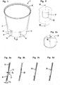
- Fig. 1 an open water overflow opening 7 is shown, while the remaining figures show an unopened water overflow opening 7.
- the openable water overflow opening 7 is sealed according to the invention by an in-mold label 10 as a film section.
- the in-mold label 10 is located on the outside of the side wall 4 and is injection-molded on the inside of the plastic of the plant container 1 in the IML injection molding process, the area designated as water overflow opening 7 not being back-injected and therefore left free.
- the in-mold label 10 is easily pierced by a sharp object. In this case, the in-mold label 10 ruptures maximally up to the edge 8, which is determined by the back-injection, and which engages in Fig. 1 indicated by a dashed line is.
- the in-mold label 10 may have a decor with a graphic or textual reference to the water overflow opening 7.
- the expired excess water is discharged from a pre-stamped in-mold label rib-shaped elevation 11 to the footprint of the plant container.
- Fig. 2 shows an interior view of the water overflow opening 7, which is formed substantially square, wherein the lower, the bottom-facing edge portion has a rounded profile.
- the detailed view according to Fig. 2a shows that the edge 8 of the openable water overflow opening 7 has a maximum distance a from its circular envelope 9, which is smaller than half of the enveloping circle radius R.
- the sectional view according to Fig. 3a shows that the wall thickness Ws of the lower edge 8 is more than 2.5 times thicker than the film thickness Fs of the in-mold label 10.
- FIGS. 3b to 3d show alternative embodiments of the water overflow opening 7. While the in-mold label 10 at the water overflow opening according to Fig. 3a extends over the full circumference of the side wall 4, it is in the embodiment according to Fig. 3b only slightly larger than the water overflow opening 7, so that it is back-injected at the edge in a width of about 3 mm. In the Fig. 3c and 3d in each case one opposite the other side wall thicker edge 8 is shown.
Description
Die vorliegende Erfindung betrifft einen Pflanzenbehälter aus Kunststoff mit einem vorzugsweise geschlossenen Boden und mit einer mit dem Boden verbundenen Seitenwand, welche eine öffnebare Wasserüberlauföffnung aufweist.The present invention relates to a plastic plant container having a preferably closed bottom and having a side wall connected to the bottom, which has an openable water overflow opening.
Aus der
Das multifunktionale Einlegeteil bildet also sowohl ein Sichtfenster als auch eine herausdrückbare Überlauföffnung aus, wobei durch den separaten Spritzvorgang des Einlegeteils ein Verschwächungsbereich mit exakt ausgeformten Dünnstellen für definierte Ausbrechkräfte geschaffen wird und durch das Umspritzen des Einlegeteils eine solche herausdrückbare Überlauföffnung in der Seitenwandung des Pflanzenbehälters integrierbar ist. Allerdings erhöht das separate Spritzgießen des Einlegeteils den Herstellungsaufwand und es sind zudem größere Wandstärken erforderlich, um das Einlegeteil durch das randseitige Umspritzen dicht und fest mit der weiteren Seitenwandung zu verbinden, damit es nicht beim Aufdrücken der Überlauföffnung mit herausgedrückt wird.Thus, the multifunctional insert part forms both a viewing window and a push-out overflow opening, wherein the separate injection process of Einlegeteils a Verschwächungsbereich is created with precisely shaped thin areas for defined Ausbrechkräfte and by overmolding of the insert such a squeezable overflow opening in the side wall of the plant container can be integrated , However, the separate injection molding of the insert increases the production cost and it also greater wall thicknesses are required to the insert by the edge-side overmolding tightly and firmly connected to the other side wall, so that it is not pressed out when pressing the overflow opening.
Es ist Aufgabe der Erfindung, einen einfacher und insbesondere kostengünstiger herzustellenden Pflanzenbehälter mit öffnebarer Wasserüberlauföffnung zu schaffen, welcher zudem in der Funktion des Öffnens der Wasserüberlauföffnung verbessert ist.It is an object of the invention to provide a simple and in particular inexpensive to produce plant container with openable water overflow opening, which is also improved in the function of opening the water overflow opening.
Die Aufgabe wird gelöst durch einen Pflanzenbehälter nach Anspruch 1. Vorteilhafte Ausgestaltungen der Erfindung sind den auf diesen Anspruch rückbezogenen Unteransprüchen sowie der nachfolgenden Figurenbeschreibung zu entnehmen.The object is achieved by a plant container according to claim 1. Advantageous embodiments of the invention are to be found in the dependent on this claim subclaims and the following description of the figures.
Erfindungsgemäß weist die Seitenwand des Pflanzenbehälters zumindest im Bereich der Wasserüberlauföffnung einen Folienabschnitt auf, welcher unter Freilassung der Wasserüberlauföffnung im Spritzgussverfahren mit Hinterspritztechnik (HST) hinterspritzt ist, wobei zumindest am unteren, dem Boden zugewandten Rand der Wasserüberlauföffnung das Verhältnis von der Wandstärke des randnah hinterspritzten Bereichs zur Folienstärke mindestens 2,5 ist. Der lediglich von der Folie gebildete Verschluss der Wasserüberlauföffnung lässt sich leicht von einem vorzugsweise spitzen Gegenstand, wie Schraubenzieher, Kugelschreiber, Schlüssel oder dergleichen Gebrauchsgegenstand, durchstechen bzw. aufdrücken und somit für den Ablauf überschüssigen Wassers öffnen. Es fällt dabei kein ggf. zu entsorgendes Abfallstück an, sondern die Folie reißt lediglich in ein oder mehreren Linien ein und verbleibt als solches an dem Pflanzenbehälter. Die eine konstante Dicke aufweisende Folie erfordert nur geringe Aufstoß- und Öffnekräfte, sodass eine Deformation und möglicherweise damit verbundene Beschädigung des insgesamt eine dünne Wandstärke aufweisenden Pflanzenbehälters vermieden wird. Die Folie reißt dabei maximal bis zum mindestens 2,5-fach dickeren, durch die Hinterspritzung definierten Rand der Wasserüberlauföffnung auf. Denn die Folie ist großflächig molekular mit dem quasi als Tragrahmen hinterspritzten Kunststoff der Seitenwandung dicht und fest verschmolzen. Im Gegensatz zu der aus dem Stand der Technik bekannten Umspritzung des Einlegeteils, die lediglich am schmalen Rand des Einlegeteils erfolgt, wird beim Hinterspritzen des Folienabschnitts eine wesentlich größere Fläche miteinander verbunden. Die verwendete Folie kann einschichtig sein oder auch mehrschichtig aufgebaut sein und weist insbesondere auf der zu hinterspritzenden Seite einen mit dem hinterspritzten Kunststoff verschmelzendes Material bzw. Beschichtung auf. Der Folienabschnitt kann von einem leichter zu zerreißenden Papier gebildet sein, das mit einer wasserdichten Kaschierung aus Kunststoff bedeckt ist.According to the invention, the side wall of the plant container, at least in the area of the water overflow opening, has a foil section which is injection-injected by means of injection molding (HST), leaving the water overflow opening at least at the lower edge of the water overflow opening facing the bottom, the ratio of the wall thickness of the back-injected area to the film thickness is at least 2.5. The closure of the water overflow opening, which is merely formed by the film, can be easily pierced or pressed by a preferably pointed object, such as screwdrivers, ball-point pens, keys or similar utensils, and thus opened for the discharge of excess water. There is no waste piece to be disposed of, but the film merely breaks into one or more lines and remains as such on the plant container. The constant thickness film requires only low impact and opening forces, thus avoiding deformation and possibly associated damage to the overall thin wallboard plant container. The film tears at most up to at least 2.5 times thicker, defined by the back injection edge of the water overflow opening. Because the film is large-scale molecularly fused tightly and firmly with the virtually as support frame back-injected plastic of the side wall. Unlike the one from the According to prior art known encapsulation of the insert, which takes place only at the narrow edge of the insert, a significantly larger area is connected to each other when injecting the film section. The film used may be single-layered or multi-layered and, in particular, has a material or coating which melts with the back-injected plastic on the side to be back-injected. The film portion may be formed from a paper which is easier to tear and which is covered with a plastic waterproof coating.
Der Folienabschnitt befindet sich in der Seitenwandung vorzugsweise außen und ist dementsprechend innenseitig hinterspritzt, wodurch sich die nach innen gerichteten Aufstoßkräfte auf dem hinterspritzten Tragrahmen abstützen und ein Ablösen des Folienabschnitts von der Seitenwandung und ein Weiteraufreißen verhindert wird. Der hinterspritzte Tragrahmen bildet also eine Matrize für das Aufstoßen der Wasserüberlauföffnung aus. Dadurch dass zumindest am unteren, dem Boden zugewandten Rand der Wasserüberlauföffnung das Verhältnis von der Wandstärke des randnah hinterspritzten Bereichs zur Folienstärke mindestens 2,5 ist, wird insbesondere verhindert, dass sich die Wasserüberlauföffnung beim Aufstechen bis unter die gewünschte Überlaufhöhe öffnet und sich dadurch das vorgesehene Volumen des Wasserspeichers verringert. Denn das Einreißen bzw. Aufplatzen der Folie endet an dem wesentlich dickeren Rand. Ein Weitereinreißen wird sicher vermieden. Vorzugsweise sind auch die sich an dem unteren Rand anschließenden und nach oben verlaufenden Randabschnitte mit einem solchen Mindestwandstärkenverhältnis ausgebildet, sodass auch ein Weitereinreißen in Umfangsrichtung sicher verhindert wird. Der Rand der öffnebaren Wasserüberlauföffnung weist vorzugsweise allseitig ein solches Mindestwandstärkenverhältnis auf. Insbesondere kann die weitere Seitenwand außerhalb des randnahen Bereichs eine dünnere Wandstärke als der randnahe Bereich aufweisen.The film section is preferably located in the side wall outside and is accordingly injected behind the inside, whereby the inwardly directed impact forces are supported on the hinterspritzten support frame and a detachment of the film portion of the side wall and further tearing is prevented. The back-injected support frame thus forms a die for the regurgitation of the water overflow opening. The fact that at least at the bottom, the bottom facing edge of the water overflow opening, the ratio of the wall thickness of the hinterspritzunter hinterspritzten area to the film thickness is at least 2.5, in particular prevents the water overflow opening opens when piercing to below the desired overflow height and thereby the intended Volume of the water storage reduced. Because the tearing or bursting of the film ends at the much thicker edge. A tear is certainly avoided. Preferably, the adjoining the lower edge and upwardly extending edge portions are formed with such a minimum wall thickness ratio, so that a further tearing in the circumferential direction is reliably prevented. The edge of the openable water overflow opening preferably has such a minimum wall thickness ratio on all sides. In particular, the additional side wall outside the region close to the edge can have a thinner wall thickness than the region near the edge.
Als randnaher Bereich wird ein Abschnitt der Seitenwand verstanden, welcher rahmenartig in einer Breite von bis zu 10 mm die Wasserüberlauföffnung umgibt. Der Querschnitt dieses randnah hinterspritzten Bereichs weist an der dicksten Stelle eine zur Folienstärke mindestens 2,5 fach dickere Wandstärke auf. Der randnahe Bereich kann dabei ein beliebiges Profil aufweisen, wie rechteckig, dreieck- oder rampenförmig usw. und dabei insbesondere abgerundet sein.A region close to the edge is understood as meaning a section of the side wall which surrounds the water overflow opening in the manner of a frame in a width of up to 10 mm. The cross section of this At the thickest point, the back-injected area has a wall thickness at least 2.5 times thicker than the thickness of the foil. The near-edge region can have any profile, such as rectangular, triangular or ramp-shaped, etc. and in particular be rounded.
Bei dem Pflanzenbehälter kann es sich um einen mit Pflanzsubstrat befüllbaren Pflanztopf oder einen den Pflanztopf aufnehmenden Übertopf handeln. Letzterer wird meist als Dekortopf verwendet. Das Erscheinungsbild eines optisch ansprechend gestalteten Dekortopfes wird von der öffnebaren Wasserüberlauföffnung, die lediglich von dem Folienabschnitt gebildet ist, nicht beeinträchtigt. Der Folienabschnitt selbst kann Teil des Dekors sein. Insbesondere kann es sich bei dem Folienabschnitt um ein im IML-Spritzgussverfahren hinterspritztes In-Mould-Label (IML) handeln, welches sich über den vollen Umfang der Seitenwand erstrecken kann. Die Folienstärke liegt im Bereich von 0,02 bis 0,4 mm, vorzugsweise 0,03 bis 0,2 mm, besonders bevorzugt 0,04 bis 0,1 mm. Eine im Bereich der Wasserüberlauföffnung frei- bzw. ausgelassene Hinterspritzung liegt auch dann vor, wenn es aufgrund von Verschleiß und Toleranzen der Spritzgussform und des eingelegten Folienabschnitt zu seitlichen Einläufen oder gar zu einer hauchdünnen, die Folienstärke unwesentlich vergrößernden Hinterspritzung der Wasserüberlauföffnung mit einem Kunststofffilm kommt. Erfindungsrelevant ist, dass der randnahe Bereich, eine gegenüber der Folien- bzw. Wandstärke der Wasserüberlauföffnung mindestens 2,5 fach dickere Wandstärke aufweist.The plant container can be a plant pot which can be filled with plant substrate or a planter which receives the plant pot. The latter is mostly used as a decorative pot. The appearance of a visually appealing Dekordopfes is not affected by the openable water overflow opening, which is formed only by the film portion. The film section itself can be part of the decor. In particular, the foil section can be an in-mold label (IML) which is back-injected in the IML injection molding process and can extend over the entire circumference of the side wall. The film thickness is in the range of 0.02 to 0.4 mm, preferably 0.03 to 0.2 mm, particularly preferably 0.04 to 0.1 mm. A back injection which is released or omitted in the region of the water overflow opening is also present when, owing to wear and tolerances of the injection mold and the inserted film section, there is lateral injection or even wafer-thin back-injection of the water overflow opening with a plastic film that does not significantly increase the film thickness. It is relevant to the invention that the region close to the edge has a wall thickness which is at least 2.5 times thicker than the thickness of the foil or wall of the water overflow opening.
Vorzugsweise ist das Verhältnis von der Wandstärke des randnah hinterspritzten Bereichs zur Folienstärke mindestens 5, weiter bevorzugt mindestens 10.Preferably, the ratio of the wall thickness of the area hinterspritzspritzten near the film thickness to the film thickness is at least 5, more preferably at least 10th
Vorzugsweise ist der Rand der öffnebaren Wasserüberlauföffnung von seiner kreisförmigen Hüllkurve nicht weiter als eine Hälfte, vorzugsweise ein Drittel des Hüllkreisradius beabstandet. Die von der Hinterspritzung begrenzte Fläche der Wasserüberlauföffnung ist im Wesentlichen quadratisch oder kreisförmig ausgebildet, wodurch das Aufstoßen der Wasserüberlauföffnung wesentlich leichter erfolgt als bei länglich ausgebildeten Bereichen. Zur Vermeidung einer Rissausbreitung in die weitere Seitenwandung aufgrund Kerbwirkung sind allenfalls vorhandene Knicke im Randverlauf in einem Winkel größer 90° ausgebildet. Vorzugsweise ist insbesondere die zum Behälterboden hin gelegene Randhälfte knickfrei ausgeführt, beispielsweise bogenförmig mit tangentialen Übergängen. Damit ist sichergestellt, dass die aufgestoßene Wasserüberlauföffnung auf die durch die Hinterspritzung begrenzte Fläche beschränkt ist.Preferably, the edge of the openable water overflow opening is spaced from its circular envelope by no more than one half, preferably one third, of the enveloping circle radius. The area of the water overflow opening delimited by the back-injection is essentially square or circular, as a result of which the water overflow opening bursts open much easier than in elongated areas. To avoid crack propagation in the further side wall due to notch effect possibly existing kinks are formed in the edge course at an angle greater than 90 °. Preferably, in particular, the half of the edge of the container towards the bottom is kink-free, for example arc-shaped with tangential transitions. This ensures that the impacted water overflow opening is limited to the area bounded by the injection.
Die öffnebare Wasserüberlauföffnung weist eine Fläche von 10 bis 1.000 mm2, vorzugsweise von 25 bis 400 mm2, besonders bevorzugt von 50 bis 125 mm2 auf, wodurch bei entsprechender Größe des Wasserspeichers bzw. des Pflanzenbehälters eine ausreichend große Überlauföffnung für einen zügigen Ablauf überschüssigen Wassers geöffnet werden kann. Es hat sich gezeigt, dass sich eine eher kleine Fläche einer Wasserüberlauföffnung leichter öffnen lässt.The openable water overflow opening has an area of 10 to 1000 mm 2 , preferably 25 to 400 mm 2 , more preferably 50 to 125 mm 2 , which, with a corresponding size of the water reservoir or the plant container, a sufficiently large overflow opening for a quick expiration surplus Water can be opened. It has been shown that a rather small area of a water overflow opening can be opened more easily.
Die öffnebare Wasserüberlauföffnung weist eine Auslaufhöhe über den Boden im Bereich von 5 bis 60 % der Behälterhöhe, vorzugsweise 10 bis 40 %, besonders bevorzugt 15 bis 35 % auf und befindet sich vorzugsweise unterhalb eines mit Substrat befüllten und in dem Pflanzenbehälter eingesetzten Pflanztopfs.The openable water overflow opening has an outlet height above the bottom in the range of 5 to 60% of the container height, preferably 10 to 40%, more preferably 15 to 35%, and is preferably below a plant pot filled with substrate and inserted in the plant container.
Vorzugsweise sind über den Umfang und/oder über die Höhe der Seitenwand verteilt wenigstens zwei wahlweise oder bedarfsweise zu öffnende Wasserüberlauföffnungen angeordnet. Es können unterschiedliche Wasserüberlaufhöhen vorgesehen sein, wobei eine jeweilige Wasserüberlauföffnung nach der Größe eines in den Pflanzenbehälter eingesetzten Pflanztopfes geöffnet werden kann. Auch können mehrere auf gleicher Höhe liegende Wasserüberlaufstellen ausgebildet sein. Sie ermöglichen es, eine bestimmte Gesamtabflussmenge einzustellen oder eine vom Dekor und dem Aufstellort des Pflanzenbehälters abhängige Öffnung bestimmter Wasserüberlauföffnungen, sodass sich der Wasserüberlauf beispielsweise auf der Rückseite des Pflanzenbehälters befindet.Preferably, over the circumference and / or over the height of the side wall at least two optionally or as needed to be opened water overflow openings are arranged. There may be provided different water overflow heights, wherein a respective water overflow opening according to the size of a plant pot used in the plant container can be opened. It is also possible for a plurality of water overflow points located at the same height to be formed. They make it possible to set a certain total discharge or a dependent on the decor and the installation of the plant container opening certain water overflow openings, so that the water overflow, for example located on the back of the plant container.
Mit dem Vorteil einer verbesserten Wahrnehmung weist die öffnebare Wasserüberlauföffnung eine von der weiteren, sie umgebenden Seitenwand in Form und/oder Beschaffenheit abweichende Oberfläche auf. Die Folie der Wasserüberlauföffnung kann beispielsweise gegenüber der sie umgebenden Seitenwand konvex vorstehen oder sie springt konkav zurück. Dieses Vor- bzw. Zurückspringen ist optisch und/oder haptisch wahrnehmbar und erleichtert das Auffinden der zu öffnenden Wasserüberlauföffnung. Eine zusätzliche Kennzeichnung kann in Fortfall gelangen. Eine solche lokale Abweichung in der Oberfläche der Seitenwandung ergibt sich bereits dadurch, dass ein nicht hinterspritzter Folienbereich eine geringere Schwindung widerfährt als mit Hinterspritzung, was sich durch Verwerfungen, Aus- oder Einbeulungen im Bereich der öffnebaren Wasserüberlauföffnung abzeichnet. Auch kann der Folienabschnitt in der Wasserüberlauföffnung vorgebeult sein und/oder eine andere Rauigkeit oder Farbe aufweisen.With the advantage of an improved perception, the openable water overflow opening has a surface deviating in shape and / or quality from the other side wall surrounding it. The foil of the water overflow opening can protrude convexly, for example, with respect to the surrounding side wall or it springs back concavely. This forward or backward jump is visually and / or haptically perceptible and makes it easier to find the water overflow opening to be opened. Additional labeling may be omitted. Such a local deviation in the surface of the side wall already results from the fact that a non-back-injected film area undergoes a lower shrinkage than with back-injection, which is manifested by warping, bulging or denting in the region of the openable water overflow opening. Also, the film portion may be pre-polished in the water overflow opening and / or have a different roughness or color.
Vorzugsweise handelt es sich bei dem Folienabschnitt um ein im IML-Spritzgussverfahren hinterspritztes In-Mould-Label (IML) ist, welches ein Dekor mit einem textlichen und/oder grafischen Hinweis auf die öffnebare Wasserüberlauföffnung aufweist. Um unterschiedliche Sprachen zu bedienen, muss lediglich das Druckbild des In-Mould-Labels geändert werden. Insbesondere kann das Dekor Hinweise enthalten, wie die Wasserüberlauföffnung geöffnet werden kann. Das In-Mould-Label kann sich über den vollen Umfang der Seitenwand erstrecken. Die Hinterspritzung des In-Mould-Labels kann mit Ausnahme der gewünschten Wasserüberlauföffnung vollflächig erfolgen oder auch nur den Behälterrand und den Behälterboden verbindende Stege oder eine Gitterstruktur umfassen, wobei zumindest ein hinterspritzter Rand um die Wasserüberlauföffnung herum vorgesehen ist. Die Hinterspritztechnik ist weitestgehend automatisierbar und ermöglicht die einwandfreie und kostengünstige Herstellung des erfindungsgemäßen Pflanzenbehälters in großen Stückzahlen.The foil section is preferably an in-mold label (IML) which is back-injected in the IML injection molding process and has a decoration with a textual and / or graphical reference to the open water overflow opening. In order to operate different languages, only the printed image of the in-mold label has to be changed. In particular, the decor may contain instructions as to how the water overflow opening can be opened. The in-mold label may extend over the full circumference of the sidewall. With the exception of the desired water overflow opening, the back-molding of the in-mold label can take place over the entire surface or can also comprise only webs and lattice structures connecting the container rim and the container bottom, at least one back-injected edge being provided around the water overflow opening. The Hinterspritztechnik is largely automated and allows the proper and cost-effective production of the plant container according to the invention in large quantities.
Mit Vorteil bildet das In-Mould-Label ein Sichtfenster mit aus, durch das der Wasserstand im Wasserspeicher abgelesen werden kann. Das Sichtfenster kann beispielsweise dadurch geschaffen werden, dass im In-Mould-Label transparente Bereiche vorliegen, die entweder nicht hinterspritzt oder von einem transparentem Kunststoff hinterspritzt sind. Auch kann das Sichtfenster im In-Mould-Label ausgespart sein, wobei dann das aus einem transparenten Kunststoff gebildete Sichtfenster von dem In-Mould-Label begrenzt ist. Das Sichtfenster ist vorzugsweise benachbart zur Wasserüberlauföffnung angeordnet und schließt sich weiter bevorzugt unterhalb der Wasserüberlauföffnung an.The in-mold label advantageously forms a window with which the water level in the water reservoir can be read off. The viewing window can be created, for example, by having transparent areas in the in-mold label which are either not back-injected or back-injected by a transparent plastic. Also, the viewing window can be recessed in the in-mold label, in which case the viewing window formed from a transparent plastic is limited by the in-mold label. The viewing window is preferably arranged adjacent to the water overflow opening and further preferably connects below the water overflow opening.
Bei der Herstellung von Pflanzenbehältern ist es außerdem möglich, wahlweise ein Folienabschnitt bzw. In-Mould-Label mit verschlossener oder geöffneter also ausgestanzter Wasserüberlauföffnung zu verwenden, um somit bereits ab Werk Pflanzenbehälter mit offener Wasserüberlauföffnung auszuliefern.In the production of plant containers, it is also possible to optionally use a film section or in-mold label with closed or opened so punched out water overflow opening, thus already delivered factory plant containers with open water overflow opening.
Vorzugsweise umfasst die Seitenwand wenigstens ein sich von der öffnebaren Wasserüberlauföffnung bis zum Boden erstreckendes Leitmittel für ablaufendes Wasser. Dabei kann es sich um eine erhabene Rippe oder einen vertieften Kanal handeln, die im In-Mould-Label vorgeprägt sind und entlang derer/dessen ablaufendes Wasser zum Boden gezielt abfließt.Preferably, the sidewall comprises at least one drainage means extending from the openable water overflow opening to the bottom. This can be a raised rib or a recessed channel, which are pre-stamped in the in-mold label and along which its effluent water flows off to the bottom.
Weitere Vorteile und Einzelheiten der Erfindung sind der nachfolgenden Figurenbeschreibung zu entnehmen. Einzelne technische Merkmale der nachfolgend beschriebenen Ausführungsbeispiele können auch in Kombination mit vorbeschriebenen Ausführungsbeispielen sowie den Merkmalen des unabhängigen Anspruchs und etwaiger weiterer Ansprüche zu erfindungsgemäßen Gegenständen kombiniert werden. Sofern sinnvoll, werden funktionell gleichwirkende Elemente mit identischen Bezugsziffern versehen. Es zeigen
- Fig. 1
- einen erfindungsgemäßen Pflanzenbehälter mit einer geöffneten Wasserüberlauföffnung;
- Fig. 2
- eine Innenansicht auf eine ungeöffnete Wasserüberlauföffnung;
- Fig. 2a
- ein Detail der Wasserüberlauföffnung aus
Fig. 2 ; - Fig. 3a
- eine Schnittansicht der Wasserüberlauföffnung aus
Fig. 2 ; - Fig. 3b-c
- Schnittansichten von weiteren Ausführungen einer Wasserüberlauföffnung.
- Fig. 1
- a plant container according to the invention with an open water overflow opening;
- Fig. 2
- an interior view of an unopened water overflow opening;
- Fig. 2a
- a detail of the water overflow opening
Fig. 2 ; - Fig. 3a
- a sectional view of the water overflow opening
Fig. 2 ; - Fig. 3b-c
- Sectional views of other versions of a water overflow opening.
Der Pflanzenbehälter 1 aus Kunststoff umfasst einen kreisförmigen Boden 3 und eine sich vom Boden zu einem Rand 5 erstreckende kegelstumpfförmige Seitenwand 4. In dem Pflanzenbehälter 1 ist ein mit Bodenlöchern versehener Pflanztopf 2 eingehängt, wobei sein Boden zum Boden 3 des Pflanzenbehälters 1 beabstandet ist. Der Raum unter dem Pflanztopf 2 dient als Wasserspeicher, aus dem eine im Pflanztopf eingesetzte Pflanze vorzugsweise über ein Dochtelement Wasser ziehen kann.The plant container 1 made of plastic comprises a
In der Seitenwand 4 befindet sich ein transparentes Sichtfenster 6, durch das der Wasserstand im Wasserspeicher abgelesen werden kann. In der Seitenwand 4 ist weiter eine Wasserüberlauföffnung 7 vorgesehen, die bei Bedarf durch einen spitzen Gegenstand geöffnet werden kann, um beispielsweise ein Übergießen oder ein Volllaufen des Pflanzenbehälters 1 bei Starkregen im Außenbereich zu verhindern. In
Die öffnebare Wasserüberlauföffnung 7 ist erfindungsgemäß durch ein In-Mould-Label 10 als Folienabschnitt verschlossen. Das In-Mould-Label 10 befindet sich auf der Außenseite der Seitenwand 4 und ist im IML-Spritzgussverfahren innenseitig vom Kunststoff des Pflanzenbehälters 1 hinterspritzt, wobei die als Wasserüberlauföffnung 7 bestimmte Fläche nicht hinterspritzt und daher freigelassen ist. Das In-Mould-Label 10 lässt sich leicht von einem spitzen Gegenstand aufstechen. Dabei reißt das In-Mould-Label 10 maximal bis zum durch die Hinterspritzung bestimmten Rand 8 auf, welcher in
Das In-Mould-Label 10 kann ein Dekor mit einem grafischen oder textlichen Hinweis auf die Wasserüberlauföffnung 7 aufweisen. Das ablaufende überschüssige Wasser wird von einer im In-Mould-Label vorgeprägten rippenförmige Erhebung 11 zur Aufstandsfläche des Pflanzenbehälters abgeleitet.The in-
Die
Claims (10)
- Plant container made from plastic material comprising a preferably closed bottom and comprising a side wall, which is connected to the bottom and has an openable water overflow opening, characterized in that the side wall has a film section at least in the area of the water overflow opening, said area being back-injection molded while leaving the water overflow opening free, and, at least at the lower edge of the water overflow opening facing the bottom, the ratio of the wall thickness of the back-injection molded area close to the edge to the film thickness is at least 2.5.
- Plant container according to claim 1, characterized in that the ratio of the wall thickness of the back-injection molded area close to the edge to the film thickness is at least 5, preferably at least 10.
- Plant container according to claim 1 or 2, characterized in that the edge of the openable water overflow opening is spaced apart from its circular enveloping curve by not more than one-half, preferably one-third, of the radius of the enveloping circle.
- Plant container according to any one of the preceding claims, characterized in that the openable water overflow opening has an area of 10 to 1,000 mm2, preferably 25 to 400 mm2, particularly preferably 50 to 125 mm2.
- Plant container according to any one of the preceding claims, characterized in that the openable water overflow opening has an outlet height above the bottom in the range from 5 to 60 % of the container height, preferably 10 to 40 %, particularly preferably 15 to 35 %.
- Plant container according to any one of the preceding claims, characterized in that at least two water overflow openings, to be opened selectively or as needed, are arranged distributed across the circumference and/or across the height of the side wall.
- Plant container according to any one of the preceding claims, characterized in that the openable water overflow opening has a surface deviating in shape and/or composition from the wider side wall surrounding it.
- Plant container according to any one of the preceding claims, characterized in that the film section is an in-mould label which has a textual and/or graphic reference to the openable water overflow opening.
- Plant container according to any one of the preceding claims, characterized in that the film section is preferably designed with a viewing window adjacent to the openable water overflow opening.
- Plant container according to any one of the preceding claims, characterized in that the side wall comprises at least one guide means extending from the openable water overflow opening to the bottom.
Applications Claiming Priority (1)
| Application Number | Priority Date | Filing Date | Title |
|---|---|---|---|
| DE202017002430.6U DE202017002430U1 (en) | 2017-05-09 | 2017-05-09 | Plant container with water overflow opening |
Publications (2)
| Publication Number | Publication Date |
|---|---|
| EP3401074A1 EP3401074A1 (en) | 2018-11-14 |
| EP3401074B1 true EP3401074B1 (en) | 2019-10-02 |
Family
ID=59118706
Family Applications (1)
| Application Number | Title | Priority Date | Filing Date |
|---|---|---|---|
| EP18000390.7A Active EP3401074B1 (en) | 2017-05-09 | 2018-04-23 | Plant container with water overflow opening |
Country Status (2)
| Country | Link |
|---|---|
| EP (1) | EP3401074B1 (en) |
| DE (1) | DE202017002430U1 (en) |
Families Citing this family (1)
| Publication number | Priority date | Publication date | Assignee | Title |
|---|---|---|---|---|
| DE202018106835U1 (en) | 2018-11-30 | 2018-12-11 | Jelenia Plast Sp. Z O.O. | Plant pot with irrigation system |
Family Cites Families (4)
| Publication number | Priority date | Publication date | Assignee | Title |
|---|---|---|---|---|
| DE29700069U1 (en) | 1997-01-07 | 1997-07-24 | Poeppelmann Kunststoff | Planter |
| KR101246648B1 (en) * | 2011-03-10 | 2013-03-25 | 이승주 | A double flowerpot |
| GB2498775A (en) * | 2012-01-27 | 2013-07-31 | Innovia Films Ltd | In-mould labelling process |
| DE202015100254U1 (en) * | 2015-01-21 | 2016-04-22 | Pöppelmann Holding GmbH & Co. KG | Storage containers |
-
2017
- 2017-05-09 DE DE202017002430.6U patent/DE202017002430U1/en not_active Expired - Lifetime
-
2018
- 2018-04-23 EP EP18000390.7A patent/EP3401074B1/en active Active
Non-Patent Citations (1)
| Title |
|---|
| None * |
Also Published As
| Publication number | Publication date |
|---|---|
| DE202017002430U1 (en) | 2017-06-07 |
| EP3401074A1 (en) | 2018-11-14 |
Similar Documents
| Publication | Publication Date | Title |
|---|---|---|
| DE102004032100B4 (en) | Method for detaching or separating a sealing film and screw caps sealed onto the edge of the neck of a bottle or the like to carry out these methods | |
| EP2231485A1 (en) | Cover for closing a container | |
| DE60306104T2 (en) | coating plate | |
| DE3714582A1 (en) | PACKAGING WITH WARRANTY LOCK | |
| EP1457301B1 (en) | Plastic container with integrated transponder | |
| DE102007060150A1 (en) | Closed sachet with sealing ring and packaging for the production thereof | |
| EP0080142A1 (en) | Threaded cap with internal cap and external cap | |
| DE102014018155A1 (en) | Tamper-evident closure for an access opening of a container, in particular a bottle | |
| EP2528803B1 (en) | Roof arrangement and method for producing a roof arrangement | |
| EP2382139A1 (en) | Screw cap having a safety ring and safety seal and method for providing a container having said screw cap | |
| EP3401074B1 (en) | Plant container with water overflow opening | |
| DE102008002853A1 (en) | Opening-and effusion element for square shaped beverage package, has hinge line extending between origin and end of effusion element, and formed with opening element using composite material, during opening process | |
| EP2496485B1 (en) | Container, in particular bottle case, having an in-mold label; methode for manufacturing the container | |
| EP3552835B1 (en) | Book-type valuable and/or security document with elastomeric binding | |
| EP1281627B1 (en) | Tamper evident container/closure assembly | |
| DE102011110548A1 (en) | Closure device for a container and method for producing such a closure device | |
| DE1432137A1 (en) | Container with cap closure | |
| DE202008006002U1 (en) | Cover for closing a container | |
| DE102017127313A1 (en) | Plastic closure for containers | |
| EP2619101A1 (en) | Folding box and closing element for same | |
| DE102010027821A1 (en) | Closure, particularly resealable closure for beverage can, has closure flap associated with framework via hinge, where closure flap is designed to cover drinking hole from inner side of framework during closed state of closure | |
| DE202021003284U1 (en) | Plastic packaging with original seal | |
| EP3418251A1 (en) | Closure for a drinks container | |
| DE102019132978A1 (en) | Use of a side protrusion as pull-out protection on a drinking straw, drinking straw and beverage packaging with a drinking straw | |
| DE19854664A1 (en) | Production of plastic container closure cap, comprises forming collar around hole in film, to engage with locating area in mold cavity |
Legal Events
| Date | Code | Title | Description |
|---|---|---|---|
| PUAI | Public reference made under article 153(3) epc to a published international application that has entered the european phase |
Free format text: ORIGINAL CODE: 0009012 |
|
| STAA | Information on the status of an ep patent application or granted ep patent |
Free format text: STATUS: THE APPLICATION HAS BEEN PUBLISHED |
|
| AK | Designated contracting states |
Kind code of ref document: A1 Designated state(s): AL AT BE BG CH CY CZ DE DK EE ES FI FR GB GR HR HU IE IS IT LI LT LU LV MC MK MT NL NO PL PT RO RS SE SI SK SM TR |
|
| AX | Request for extension of the european patent |
Extension state: BA ME |
|
| STAA | Information on the status of an ep patent application or granted ep patent |
Free format text: STATUS: REQUEST FOR EXAMINATION WAS MADE |
|
| 17P | Request for examination filed |
Effective date: 20190606 |
|
| RBV | Designated contracting states (corrected) |
Designated state(s): AL AT BE BG CH CY CZ DE DK EE ES FI FR GB GR HR HU IE IS IT LI LT LU LV MC MK MT NL NO PL PT RO RS SE SI SK SM TR |
|
| GRAP | Despatch of communication of intention to grant a patent |
Free format text: ORIGINAL CODE: EPIDOSNIGR1 |
|
| STAA | Information on the status of an ep patent application or granted ep patent |
Free format text: STATUS: GRANT OF PATENT IS INTENDED |
|
| GRAS | Grant fee paid |
Free format text: ORIGINAL CODE: EPIDOSNIGR3 |
|
| INTG | Intention to grant announced |
Effective date: 20190726 |
|
| GRAA | (expected) grant |
Free format text: ORIGINAL CODE: 0009210 |
|
| STAA | Information on the status of an ep patent application or granted ep patent |
Free format text: STATUS: THE PATENT HAS BEEN GRANTED |
|
| AK | Designated contracting states |
Kind code of ref document: B1 Designated state(s): AL AT BE BG CH CY CZ DE DK EE ES FI FR GB GR HR HU IE IS IT LI LT LU LV MC MK MT NL NO PL PT RO RS SE SI SK SM TR |
|
| REG | Reference to a national code |
Ref country code: GB Ref legal event code: FG4D Free format text: NOT ENGLISH |
|
| REG | Reference to a national code |
Ref country code: CH Ref legal event code: EP Ref country code: AT Ref legal event code: REF Ref document number: 1185704 Country of ref document: AT Kind code of ref document: T Effective date: 20191015 |
|
| REG | Reference to a national code |
Ref country code: DE Ref legal event code: R096 Ref document number: 502018000248 Country of ref document: DE |
|
| REG | Reference to a national code |
Ref country code: IE Ref legal event code: FG4D Free format text: LANGUAGE OF EP DOCUMENT: GERMAN |
|
| REG | Reference to a national code |
Ref country code: NL Ref legal event code: FP |
|
| REG | Reference to a national code |
Ref country code: LT Ref legal event code: MG4D |
|
| PG25 | Lapsed in a contracting state [announced via postgrant information from national office to epo] |
Ref country code: NO Free format text: LAPSE BECAUSE OF FAILURE TO SUBMIT A TRANSLATION OF THE DESCRIPTION OR TO PAY THE FEE WITHIN THE PRESCRIBED TIME-LIMIT Effective date: 20200102 Ref country code: BG Free format text: LAPSE BECAUSE OF FAILURE TO SUBMIT A TRANSLATION OF THE DESCRIPTION OR TO PAY THE FEE WITHIN THE PRESCRIBED TIME-LIMIT Effective date: 20200102 Ref country code: LT Free format text: LAPSE BECAUSE OF FAILURE TO SUBMIT A TRANSLATION OF THE DESCRIPTION OR TO PAY THE FEE WITHIN THE PRESCRIBED TIME-LIMIT Effective date: 20191002 Ref country code: PL Free format text: LAPSE BECAUSE OF FAILURE TO SUBMIT A TRANSLATION OF THE DESCRIPTION OR TO PAY THE FEE WITHIN THE PRESCRIBED TIME-LIMIT Effective date: 20191002 Ref country code: GR Free format text: LAPSE BECAUSE OF FAILURE TO SUBMIT A TRANSLATION OF THE DESCRIPTION OR TO PAY THE FEE WITHIN THE PRESCRIBED TIME-LIMIT Effective date: 20200103 Ref country code: ES Free format text: LAPSE BECAUSE OF FAILURE TO SUBMIT A TRANSLATION OF THE DESCRIPTION OR TO PAY THE FEE WITHIN THE PRESCRIBED TIME-LIMIT Effective date: 20191002 Ref country code: SE Free format text: LAPSE BECAUSE OF FAILURE TO SUBMIT A TRANSLATION OF THE DESCRIPTION OR TO PAY THE FEE WITHIN THE PRESCRIBED TIME-LIMIT Effective date: 20191002 Ref country code: LV Free format text: LAPSE BECAUSE OF FAILURE TO SUBMIT A TRANSLATION OF THE DESCRIPTION OR TO PAY THE FEE WITHIN THE PRESCRIBED TIME-LIMIT Effective date: 20191002 Ref country code: PT Free format text: LAPSE BECAUSE OF FAILURE TO SUBMIT A TRANSLATION OF THE DESCRIPTION OR TO PAY THE FEE WITHIN THE PRESCRIBED TIME-LIMIT Effective date: 20200203 Ref country code: FI Free format text: LAPSE BECAUSE OF FAILURE TO SUBMIT A TRANSLATION OF THE DESCRIPTION OR TO PAY THE FEE WITHIN THE PRESCRIBED TIME-LIMIT Effective date: 20191002 |
|
| PG25 | Lapsed in a contracting state [announced via postgrant information from national office to epo] |
Ref country code: IS Free format text: LAPSE BECAUSE OF FAILURE TO SUBMIT A TRANSLATION OF THE DESCRIPTION OR TO PAY THE FEE WITHIN THE PRESCRIBED TIME-LIMIT Effective date: 20200224 Ref country code: RS Free format text: LAPSE BECAUSE OF FAILURE TO SUBMIT A TRANSLATION OF THE DESCRIPTION OR TO PAY THE FEE WITHIN THE PRESCRIBED TIME-LIMIT Effective date: 20191002 Ref country code: HR Free format text: LAPSE BECAUSE OF FAILURE TO SUBMIT A TRANSLATION OF THE DESCRIPTION OR TO PAY THE FEE WITHIN THE PRESCRIBED TIME-LIMIT Effective date: 20191002 Ref country code: CZ Free format text: LAPSE BECAUSE OF FAILURE TO SUBMIT A TRANSLATION OF THE DESCRIPTION OR TO PAY THE FEE WITHIN THE PRESCRIBED TIME-LIMIT Effective date: 20191002 |
|
| PG25 | Lapsed in a contracting state [announced via postgrant information from national office to epo] |
Ref country code: AL Free format text: LAPSE BECAUSE OF FAILURE TO SUBMIT A TRANSLATION OF THE DESCRIPTION OR TO PAY THE FEE WITHIN THE PRESCRIBED TIME-LIMIT Effective date: 20191002 |
|
| REG | Reference to a national code |
Ref country code: DE Ref legal event code: R097 Ref document number: 502018000248 Country of ref document: DE |
|
| PG2D | Information on lapse in contracting state deleted |
Ref country code: IS |
|
| PG25 | Lapsed in a contracting state [announced via postgrant information from national office to epo] |
Ref country code: DK Free format text: LAPSE BECAUSE OF FAILURE TO SUBMIT A TRANSLATION OF THE DESCRIPTION OR TO PAY THE FEE WITHIN THE PRESCRIBED TIME-LIMIT Effective date: 20191002 Ref country code: RO Free format text: LAPSE BECAUSE OF FAILURE TO SUBMIT A TRANSLATION OF THE DESCRIPTION OR TO PAY THE FEE WITHIN THE PRESCRIBED TIME-LIMIT Effective date: 20191002 Ref country code: EE Free format text: LAPSE BECAUSE OF FAILURE TO SUBMIT A TRANSLATION OF THE DESCRIPTION OR TO PAY THE FEE WITHIN THE PRESCRIBED TIME-LIMIT Effective date: 20191002 Ref country code: IS Free format text: LAPSE BECAUSE OF FAILURE TO SUBMIT A TRANSLATION OF THE DESCRIPTION OR TO PAY THE FEE WITHIN THE PRESCRIBED TIME-LIMIT Effective date: 20200202 |
|
| PLBE | No opposition filed within time limit |
Free format text: ORIGINAL CODE: 0009261 |
|
| STAA | Information on the status of an ep patent application or granted ep patent |
Free format text: STATUS: NO OPPOSITION FILED WITHIN TIME LIMIT |
|
| PG25 | Lapsed in a contracting state [announced via postgrant information from national office to epo] |
Ref country code: SK Free format text: LAPSE BECAUSE OF FAILURE TO SUBMIT A TRANSLATION OF THE DESCRIPTION OR TO PAY THE FEE WITHIN THE PRESCRIBED TIME-LIMIT Effective date: 20191002 Ref country code: SM Free format text: LAPSE BECAUSE OF FAILURE TO SUBMIT A TRANSLATION OF THE DESCRIPTION OR TO PAY THE FEE WITHIN THE PRESCRIBED TIME-LIMIT Effective date: 20191002 Ref country code: IT Free format text: LAPSE BECAUSE OF FAILURE TO SUBMIT A TRANSLATION OF THE DESCRIPTION OR TO PAY THE FEE WITHIN THE PRESCRIBED TIME-LIMIT Effective date: 20191002 |
|
| 26N | No opposition filed |
Effective date: 20200703 |
|
| PG25 | Lapsed in a contracting state [announced via postgrant information from national office to epo] |
Ref country code: MC Free format text: LAPSE BECAUSE OF FAILURE TO SUBMIT A TRANSLATION OF THE DESCRIPTION OR TO PAY THE FEE WITHIN THE PRESCRIBED TIME-LIMIT Effective date: 20191002 Ref country code: SI Free format text: LAPSE BECAUSE OF FAILURE TO SUBMIT A TRANSLATION OF THE DESCRIPTION OR TO PAY THE FEE WITHIN THE PRESCRIBED TIME-LIMIT Effective date: 20191002 |
|
| PG25 | Lapsed in a contracting state [announced via postgrant information from national office to epo] |
Ref country code: FR Free format text: LAPSE BECAUSE OF NON-PAYMENT OF DUE FEES Effective date: 20200430 Ref country code: LU Free format text: LAPSE BECAUSE OF NON-PAYMENT OF DUE FEES Effective date: 20200423 |
|
| REG | Reference to a national code |
Ref country code: BE Ref legal event code: MM Effective date: 20200430 |
|
| PG25 | Lapsed in a contracting state [announced via postgrant information from national office to epo] |
Ref country code: BE Free format text: LAPSE BECAUSE OF NON-PAYMENT OF DUE FEES Effective date: 20200430 |
|
| PG25 | Lapsed in a contracting state [announced via postgrant information from national office to epo] |
Ref country code: IE Free format text: LAPSE BECAUSE OF NON-PAYMENT OF DUE FEES Effective date: 20200423 |
|
| PG25 | Lapsed in a contracting state [announced via postgrant information from national office to epo] |
Ref country code: LI Free format text: LAPSE BECAUSE OF NON-PAYMENT OF DUE FEES Effective date: 20210430 Ref country code: CH Free format text: LAPSE BECAUSE OF NON-PAYMENT OF DUE FEES Effective date: 20210430 |
|
| PG25 | Lapsed in a contracting state [announced via postgrant information from national office to epo] |
Ref country code: TR Free format text: LAPSE BECAUSE OF FAILURE TO SUBMIT A TRANSLATION OF THE DESCRIPTION OR TO PAY THE FEE WITHIN THE PRESCRIBED TIME-LIMIT Effective date: 20191002 Ref country code: MT Free format text: LAPSE BECAUSE OF FAILURE TO SUBMIT A TRANSLATION OF THE DESCRIPTION OR TO PAY THE FEE WITHIN THE PRESCRIBED TIME-LIMIT Effective date: 20191002 Ref country code: CY Free format text: LAPSE BECAUSE OF FAILURE TO SUBMIT A TRANSLATION OF THE DESCRIPTION OR TO PAY THE FEE WITHIN THE PRESCRIBED TIME-LIMIT Effective date: 20191002 |
|
| PG25 | Lapsed in a contracting state [announced via postgrant information from national office to epo] |
Ref country code: MK Free format text: LAPSE BECAUSE OF FAILURE TO SUBMIT A TRANSLATION OF THE DESCRIPTION OR TO PAY THE FEE WITHIN THE PRESCRIBED TIME-LIMIT Effective date: 20191002 |
|
| GBPC | Gb: european patent ceased through non-payment of renewal fee |
Effective date: 20220423 |
|
| PG25 | Lapsed in a contracting state [announced via postgrant information from national office to epo] |
Ref country code: GB Free format text: LAPSE BECAUSE OF NON-PAYMENT OF DUE FEES Effective date: 20220423 |
|
| PGFP | Annual fee paid to national office [announced via postgrant information from national office to epo] |
Ref country code: NL Payment date: 20230417 Year of fee payment: 6 |
|
| PGFP | Annual fee paid to national office [announced via postgrant information from national office to epo] |
Ref country code: DE Payment date: 20230418 Year of fee payment: 6 |