EP3401032B1 - Composite tool and method for producing a sheet component - Google Patents
Composite tool and method for producing a sheet component Download PDFInfo
- Publication number
- EP3401032B1 EP3401032B1 EP18171616.8A EP18171616A EP3401032B1 EP 3401032 B1 EP3401032 B1 EP 3401032B1 EP 18171616 A EP18171616 A EP 18171616A EP 3401032 B1 EP3401032 B1 EP 3401032B1
- Authority
- EP
- European Patent Office
- Prior art keywords
- die
- cutting edge
- punch
- sheet metal
- cutting
- Prior art date
- Legal status (The legal status is an assumption and is not a legal conclusion. Google has not performed a legal analysis and makes no representation as to the accuracy of the status listed.)
- Active
Links
- 239000002131 composite material Substances 0.000 title claims description 84
- 238000004519 manufacturing process Methods 0.000 title claims description 39
- 238000005520 cutting process Methods 0.000 claims description 253
- 229910052751 metal Inorganic materials 0.000 claims description 140
- 239000002184 metal Substances 0.000 claims description 140
- 238000009966 trimming Methods 0.000 claims description 48
- 238000003825 pressing Methods 0.000 claims description 26
- 238000003780 insertion Methods 0.000 claims description 18
- 230000037431 insertion Effects 0.000 claims description 18
- 230000007704 transition Effects 0.000 claims description 18
- 238000013461 design Methods 0.000 claims description 11
- 230000000284 resting effect Effects 0.000 claims description 2
- 238000010008 shearing Methods 0.000 claims description 2
- 239000002699 waste material Substances 0.000 description 54
- 238000004049 embossing Methods 0.000 description 50
- 238000000034 method Methods 0.000 description 32
- 230000008569 process Effects 0.000 description 25
- 238000005452 bending Methods 0.000 description 18
- 238000011161 development Methods 0.000 description 16
- 230000018109 developmental process Effects 0.000 description 16
- 241000985128 Cladium mariscus Species 0.000 description 14
- 239000011159 matrix material Substances 0.000 description 14
- 150000001875 compounds Chemical class 0.000 description 10
- 230000010354 integration Effects 0.000 description 9
- 238000007493 shaping process Methods 0.000 description 7
- 238000007688 edging Methods 0.000 description 6
- 239000000463 material Substances 0.000 description 6
- 125000006850 spacer group Chemical group 0.000 description 6
- 230000000295 complement effect Effects 0.000 description 5
- 238000004080 punching Methods 0.000 description 5
- 239000011324 bead Substances 0.000 description 4
- 238000003754 machining Methods 0.000 description 3
- 238000012545 processing Methods 0.000 description 3
- 238000004904 shortening Methods 0.000 description 3
- 238000013459 approach Methods 0.000 description 2
- 238000005253 cladding Methods 0.000 description 2
- 238000010276 construction Methods 0.000 description 2
- 230000007547 defect Effects 0.000 description 2
- 230000000694 effects Effects 0.000 description 2
- 238000005304 joining Methods 0.000 description 2
- 239000007769 metal material Substances 0.000 description 2
- 230000002093 peripheral effect Effects 0.000 description 2
- 230000000750 progressive effect Effects 0.000 description 2
- 238000012546 transfer Methods 0.000 description 2
- 241000239290 Araneae Species 0.000 description 1
- 241001295925 Gegenes Species 0.000 description 1
- 206010038743 Restlessness Diseases 0.000 description 1
- 229910000831 Steel Inorganic materials 0.000 description 1
- 230000009471 action Effects 0.000 description 1
- 229910052782 aluminium Inorganic materials 0.000 description 1
- XAGFODPZIPBFFR-UHFFFAOYSA-N aluminium Chemical compound [Al] XAGFODPZIPBFFR-UHFFFAOYSA-N 0.000 description 1
- 230000009286 beneficial effect Effects 0.000 description 1
- 230000015572 biosynthetic process Effects 0.000 description 1
- 230000000903 blocking effect Effects 0.000 description 1
- 239000011248 coating agent Substances 0.000 description 1
- 238000000576 coating method Methods 0.000 description 1
- 239000000428 dust Substances 0.000 description 1
- 238000005516 engineering process Methods 0.000 description 1
- 238000010438 heat treatment Methods 0.000 description 1
- 238000009957 hemming Methods 0.000 description 1
- 238000010348 incorporation Methods 0.000 description 1
- 238000007373 indentation Methods 0.000 description 1
- 230000003993 interaction Effects 0.000 description 1
- 238000012423 maintenance Methods 0.000 description 1
- 238000000465 moulding Methods 0.000 description 1
- 239000002245 particle Substances 0.000 description 1
- 230000008092 positive effect Effects 0.000 description 1
- 230000009467 reduction Effects 0.000 description 1
- 238000006748 scratching Methods 0.000 description 1
- 230000002393 scratching effect Effects 0.000 description 1
- 238000000926 separation method Methods 0.000 description 1
- 239000010959 steel Substances 0.000 description 1
- XLYOFNOQVPJJNP-UHFFFAOYSA-N water Substances O XLYOFNOQVPJJNP-UHFFFAOYSA-N 0.000 description 1
Images


Classifications
-
- B—PERFORMING OPERATIONS; TRANSPORTING
- B21—MECHANICAL METAL-WORKING WITHOUT ESSENTIALLY REMOVING MATERIAL; PUNCHING METAL
- B21D—WORKING OR PROCESSING OF SHEET METAL OR METAL TUBES, RODS OR PROFILES WITHOUT ESSENTIALLY REMOVING MATERIAL; PUNCHING METAL
- B21D24/00—Special deep-drawing arrangements in, or in connection with, presses
- B21D24/04—Blank holders; Mounting means therefor
-
- B—PERFORMING OPERATIONS; TRANSPORTING
- B21—MECHANICAL METAL-WORKING WITHOUT ESSENTIALLY REMOVING MATERIAL; PUNCHING METAL
- B21D—WORKING OR PROCESSING OF SHEET METAL OR METAL TUBES, RODS OR PROFILES WITHOUT ESSENTIALLY REMOVING MATERIAL; PUNCHING METAL
- B21D22/00—Shaping without cutting, by stamping, spinning, or deep-drawing
- B21D22/02—Stamping using rigid devices or tools
- B21D22/06—Stamping using rigid devices or tools having relatively-movable die parts
-
- B—PERFORMING OPERATIONS; TRANSPORTING
- B21—MECHANICAL METAL-WORKING WITHOUT ESSENTIALLY REMOVING MATERIAL; PUNCHING METAL
- B21D—WORKING OR PROCESSING OF SHEET METAL OR METAL TUBES, RODS OR PROFILES WITHOUT ESSENTIALLY REMOVING MATERIAL; PUNCHING METAL
- B21D35/00—Combined processes according to or processes combined with methods covered by groups B21D1/00 - B21D31/00
- B21D35/001—Shaping combined with punching, e.g. stamping and perforating
Definitions
- the invention relates to a composite tool according to the preamble of claim 1 and a manufacturing method according to the preamble of claim 15.
- a composite tool and a corresponding manufacturing method are from WO 2008/025387 A1 known.
- Composite tools and in particular complete composite tools are usually characterized in that at least two technologically different machining processes are carried out in one tool and in one press stroke. In other words, multiple operations or functions are integrated into one tool or machining step.
- composite tools have so far mainly been used for geometrically simple components, which are usually made from a sheet metal strip. In the manufacture of large, complex sheet metal components, e.g.
- Body panel parts are typically manufactured in a sequence of operations of drawing, trimming, piercing and final forming in multiple tools or tooling stages.
- the finish forming can in particular represent a bending operation.
- drawing the basic component shape from a flat sheet metal blank is the first operation in the manufacturing process with line or transfer tools.
- Drawing is typically a deep-drawing, stretch-drawing or a combined process in one tool. Then, in operations that are separate from drawing, further steps such as punching, cutting and final shaping take place.
- Post-forming or final forming are also understood to mean shaping operations, mostly in the last tool stage. Bending is a process of reshaping or finishing. The edge of the drawn and trimmed sheet metal part is "bent" by about 90°. Folded rims on sheet metal parts are used, for example, as joining flanges or as a preform for a flanging or roll hemming operation in the body shell, where the individual part is joined with others to form an assembly. In most cases, the bending is done in the last operation.
- the Figure 16A shows schematically a sequence of operations known from the prior art of drawing-trimming-bending on a body component K.
- the body component K is drawn from a sheet metal blank K' (1.), before it is trimmed in a separate tool (2.) and Edge section Ka is folded (3.).
- Edge section Ka is folded (3.).
- the Figure 16B illustrated in more detail.
- the Figures 16A and 16B each show the simple case in which all operations can be carried out in the working direction of a press.
- a tool element folding strip
- post-forming or final forming are, for example, refacing or calibrating.
- a component that has already been formed is acted on in certain areas in order to influence its geometry locally.
- embossings are introduced or radii are reduced.
- the invention is based on the object of reducing the total number of tools required to manufacture a sheet metal component and thereby reducing operating costs and development and procurement times and shortening process chains.
- the translationally adjustable blank holder in cooperation with the at least two-part die, ensures the defined position and alignment of the waste piece to be separated and, thanks to its adjustability relative to the punch, ensures the integration of a trimming operation in the press stroke.
- pressing the two-part die and the punch against each other means in particular that the two-part die and the punch are displaced towards one another under the action of an adjustment force applied by a press (equipped with the composite tool) and an actual pressing of at least one Part of the at least two-part die against the punch only takes place at the end of the drawing process.
- pressing the two-part die and the punch against each other and thus associated with the shift for the actual, later pressing of (drawing) die and (drawing) punch, for example, initially only the outer die against the blank holder - in the actual sense - "pressed". In particular, this includes the fact that the outer die is pressed against the blank holder during the entire drawing process and that the inner die is only pressed against the punch at the end of the drawing process.
- That the inner die and the outer die are adjustable relative to each other on the first structure includes both the inner die being adjustable relative to the outer die and the outer die being adjustable relative to the inner die. Due to the adjustability of the inner and outer dies relative to each other on the first structure and the interaction with the adjustable sheet metal holder of the second structure, the waste piece can be separated particularly easily via the press stroke.
- the outer matrix of the first structure can at least partially enclose the inner matrix.
- the outer die has a first form-fitting area and the sheet metal holder has a second form-fitting area.
- the waste piece of the sheet metal blank is (locally) deformed during pressing via the first and second form-fitting areas of the outer die and the blank holder, so that at least one area of the waste piece engages in at least one of the first and second form-fitting areas and/or at least one of the first and second form-fitting areas positively engages in the piece of waste.
- the first and second form-fitting areas can thus serve to fix the waste piece between the sheet metal holder and the outer die during pressing, although this is not the case is mandatory.
- the first and second form-fitting areas can be formed, for example, as projections and/or indentations. For example, a bulge is provided on the outer die to produce a corresponding bead on the waste piece of the sheet metal blank.
- the composite tool is thus set up to simultaneously use a pressing force applied for forming the sheet metal blank to separate an outer edge of the sheet metal blank as a waste piece and thus to trim the sheet metal blank. If necessary, the edge of the sheet metal component is also finish-formed, or at least reshaped. In one press stroke, in addition to forming, trimming and e.g. edge bending or folding takes place.
- the first structure and the second structure can consequently not only be set up to also separate an outer edge of the sheet metal blank as a waste piece when the die and the punch are pressed against one another.
- the first structure and the second structure can also be set up to reshape an edge section of the sheet metal component, on which there is a separating edge resulting from the cutting off of the waste piece, before or after the cutting off of the waste piece.
- the edge section of the sheet metal component on which the separating edge is present is bent before the waste piece is cut off or folded after the waste piece is cut off.
- a press on which the composite tool is set up with the first and second structures represents the sole drive for all tool functions, i.e. no further hydraulic or other actuators are used to implement the trimming and final forming.
- At least one subsequent operation can be integrated in the drawing tool via the inner and outer matrices that can be adjusted relative to one another.
- at least one external trimming of the sheet metal component is integrated into the drawing stage. This can in particular be a circumferential trimming, and therefore a complete trimming.
- the pulling and the trimming take place in a continuous stroke of the composite tool.
- the created separating or trimming edge can represent the contour of the finished part as well as be further processed in further operations, eg bending or reshaping.
- the composite tool according to the invention makes it possible to reduce the number of tools for the production of a sheet metal component by at least one operation.
- the invention is not limited to body components for motor vehicles, for example, but also extends to the production of other flat sheet metal components, in particular sheet metal components made of steel, aluminum or other materials.
- edge trimming of the sheet metal blank must also be separated from the setting of a relief slot in an inner waste area of the component, e.g. in a window opening.
- a relief cut is made during the forming, which promotes the material flow from "inside to outside".
- this is only a line-shaped cut, i.e. no trimming operation. This operation does not produce any waste that would have to be removed from the tool.
- the area of the relief incision made is only cut out in a subsequent operation. Consequently, it is not a matter of integrating a crop operation into the drawing tool.
- the composite tool integrates a circumferential outer component trimming in the drawing stage. Further operations can be integrated into the drawing stage in possible further developments. This involves, for example, the integration of drawing, cutting and edging or drawing, cutting, edging and embossing. This makes it possible, for example, to realize the entire production sequence of a sheet metal component in the composite tool and in a press stroke implemented with it.
- the proposed solution also differs from progressive dies, which are characterized in that the components are manufactured from a sheet metal strip (from a coil) that is pushed or pulled step by step through a sequence of several tool stages. The finished component is only separated from the strip in the last stage.
- progressive dies in usually only small to medium-sized, geometrically simple components are manufactured in large quantities.
- the composite tool typically forms a component-specific pressing tool in which a sheet metal blank is formed globally. This is followed by severing, preferably shearing at the periphery of the three-dimensionally shaped geometry, no laser or water jet cutting in the horizontal plane. In addition, the sheet metal component is not cut out, but a waste piece is cut off from the sheet metal blank.
- the sheet metal holder on the second structure can be adjusted relative to the stamp into an insertion position onto the outer die.
- the sheet metal blank is to be arranged with an edge section on the sheet metal holder.
- the blank holder can be adjusted relative to the punch into a holding position different from the insertion position, in which the waste piece separated from the sheet metal blank is held between the outer die and the blank holder.
- the sheet metal holder is displaced from the insertion position under the influence of the first structure and in particular of the outer die adjusted with the first structure.
- the waste piece of the sheet metal blank provided between the outer die and the adjustable sheet metal holder is optionally reshaped in a defined manner.
- the separated piece of scrap is held in a defined position at the end of the press stroke by the sheet metal holder, which can be adjusted relative to the stamp, and can be displaced relative to the finished sheet metal component. This is particularly advantageous with a view to removing the waste piece from the composite tool.
- the proposed composite tool is set up to use a pressing force applied for forming the sheet metal blank and thus the press stroke at the same time to separate the waste piece and, if necessary, to finish-form the edge of the sheet metal component. Accordingly, then in one embodiment by the translational adjustment of the first structure and the second structure on each other to the sheet metal holder relative to the punch and / or inner and outer matrices are adjusted relative to each other.
- the blank holder is thus, for example, during the press stroke relative to the ram not externally operated by an additional drive adjustable, but only by the press force.
- a movement of the sheet metal holder relative to the punch is thus caused solely by the adjustment of the first and second structures toward one another and the press stroke thus implemented.
- An additional (motorized) adjustment drive is not provided for this. The same applies to the alternatively or additionally provided adjustment of inner and outer matrices relative to each other during pressing.
- a stamp attachment is additionally provided on the second structure, which is arranged between the sheet metal holder and an insertion area for a cutting edge of the first structure.
- an additional punch attachment for example, it is possible to design a drawing shell in the composite tool with an open-angled frame. This in turn allows the sheet metal blank to be stretched out into the middle of the component. This is necessary, for example, for flat outer skin parts such as roofs or outer door panels as (body) sheet metal components to be manufactured.
- the punch attachment is adjacent to an area of the second structure, the insertion area, into which a cutting edge of the second structure provided for cutting the sheet metal blank can dip during pressing.
- the stamp attachment is opposite a hold-down device of the first structure.
- the punch attachment can be at a distance from the punch and, on the other hand, from the sheet metal holder (transverse to the direction of adjustment of the sheet metal holder).
- the stamp construction can also be an integral part of the stamp.
- the first structure and the second structure of the composite tool can be set up so that the waste piece can be separated by shear cutting when the die and the punch are pressed against one another.
- a cutting edge can be formed on the outer die or a cutting edge can be mounted in one variant for separating the waste piece.
- an edge of the outer die adjacent to the inner die forms a cutting edge for severing the waste piece.
- the outer die is here (possibly together with the blank holder opposite) during the Adjusted press stroke relative to the inner die.
- a separate cutting edge or a cutting knife with such a cutting edge is mounted on the outer die.
- a cutting edge (of a cutting knife) is provided on the first structure, relative to which the inner die of the at least two-part die is mounted adjustably on the first structure.
- the inner die is displaced counter to the direction of adjustment with respect to the cutting edge, so that the cutting edge separates the waste piece as the first structure is adjusted further, possibly forming the separating edge adjacent to it the inner matrix.
- the cutting edge is designed with a cutting strip which (a) simultaneously acts as a folding strip when the die and the punch are pressed against one another or which (b) interacts with a counterholder when the die and the stamp are pressed against one another and then acts as a folding strip against the latter Counterholder works.
- the cutting bar is intended, for example, for edging a flared and/or multiple-stepped rim when pressing the die and the punch against each other.
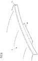
- a cutting edge of the cutting strip has at least one first cutting edge section and at least one second cutting edge section, wherein, based on a direction pointing from the inner die to the outer die, the at least one first cutting edge section is on the inside and the at least one second cutting edge section is on the outside. so that an inner contour of the cutting edge is defined with the at least one first cutting edge section and an outer contour of the cutting edge is defined with the at least one second cutting edge section.
- the protrusion of different cutting edge sections can prove to be particularly advantageous if two edge regions are to be provided on the component, one edge region of which is finished after drawing and trimming, while an adjacent edge region still needs a bevel after drawing and trimming of a laid out rim must be subjected.
- the movable cutting bar is then designed differently for these different edge areas.
- the at least one second cutting edge section defining the outer contour The cutting edge protrudes relative to the at least one first cutting edge section defining the inner contour, for example in an adjustment direction of the cutting edge, in which the cutting edge is adjusted relative to one another when the die and the punch are pressed.
- the cutting edge first uses the second cutting edge section of its cutting edge to trim the sheet metal blank in a second (subsequently beveled) edge region, before the cutting edge uses the first cutting edge section of its cutting edge to trim the sheet metal blank in a different manner makes the first edge area.
- the at least one second cutting edge section of the cutting edge that defines the outer contour protrudes from the at least one first cutting edge section that defines the inner contour - depending on the component geometry, process, sheet metal material and thickness, e.g. by 0.5 mm to 3.0 mm.
- a projection in the range from 0.7 mm to 1.4 mm is provided.
- the second cutting edge section thus runs ahead by a certain amount compared to the cutting edge section for the first edge area, specifically by 0.5 mm to 3.0 mm, for example. As a result, the trimming is carried out in the second edge area first.
- a counter-holder interacting with the cutting strip can also be designed and provided to act against one another as a counter-knife when pressing the die and the punch for a transition region of the cutting edge, where the cutting edge transitions from the at least one first cutting-edge section into the at least one second cutting-edge section.
- a counterholder that interacts with the cutting strip can be designed and provided to be displaced when the die and the punch are pressed against one another by the cutting edge resting against the counterholder with the at least one first cutting edge section, after which the at least one second cutting edge section can be used the sheet metal blank has been trimmed.
- the cutting strip sits on the counterholder in the first edge area and begins to push it down against a defined force as the press stroke progresses.
- a contour of a counterholder that interacts with the cutting strip is designed as an undercutter for a transition area of the cutting edge, where the cutting edge transitions from the at least one first cutting edge section to the at least one second cutting edge section.
- the trimming is carried out in advance in the first edge area and then peels over the transition edge area. Finally, the second edge area is cut and folded.
- a cutting insert can be provided on an upper or lower cutter in a transition area.
- the first structure and the second structure can also be set up to provide at least one embossing on the edge section of the sheet metal component to be produced by pressing the dies and the stamp against one another.
- at least one embossed or stepped forming surface for the sheet metal blank is provided on an optionally adjustable counterholder of the first or second structure, so that during the press stroke and the sheet metal blank is inserted as intended into the composite tool, there is a corresponding embossing on the finished edge section at the end of the press stroke.
- a shaping surface for embossing can be provided, for example, on the first structure on a cutting, folding or embossing bar and/or on the second structure on the stamp.
- the cutting edge of the first structure, relative to which the inner die is mounted adjustably can also be designed with a cutting strip which, when the die and the punch are pressed against one another, acts simultaneously as a folding strip and as a shaping strip for providing the embossing in order to to provide the embossing on a flared edge of the edge section.
- an (embossing) insert can be provided on the first structure, by means of which an embossing is made in the component surface (and thus not on a peripheral flange), in particular a door handle recess, during drawing or after drawing is complete.
- the integration of an embossing process for producing an embossing in the component surface in the press stroke can make it easier to achieve a higher surface quality.
- the (embossing) insert is the The sheet metal blank is still under a certain degree of biaxial tensile stress from the drawing process and the component surface to be stamped is held between the punch and the inner die. This biaxial tensile stress superimposes the stress conditions created by the embossing process in and around the embossment and mitigates the influence of the different unfolding lengths across the embossment.
- a punch for producing at least one hole in the sheet metal component is provided on the first structure.
- the punch can be provided for producing the at least one hole on the embossing produced by means of the insert.
- the insert is then e.g the punch produces at least one hole. Embossing and perforation can thus also be produced here using the composite tool in one press stroke. It can be particularly advantageous here if the punch is guided in the (embossing) insert and the insert (in the second adjustment phase) assumes the function of a hold-down device.
- the composite tool can be designed as an overall composite tool and/or be set up and provided in particular for the production of a flat body component for a motor vehicle.
- a flat body part is a roof paneling.
- Another flat body component can be, for example, a door panel, in particular an outer door panel of a motor vehicle door.
- a further aspect of the proposed solution relates to a method for producing a flat sheet metal component by means of a press device which comprises a first structure having a die and a second structure having a stamp.
- the proposed method provides that with the pressing of the die and the punch against each other in order to shape the sheet metal component by drawing, an outer edge of the sheet metal blank is also separated as a waste piece and thus a trimming of the sheet metal blank is also carried out within the composite tool.
- a sheet metal holder that can be adjusted in a translatory manner relative to the stamp is used at least, on which a outer edge of the sheet metal blank to be drawn is held.
- an at least two-part die with an inner die and an outer die is used, in which the inner die and the outer die can be adjusted relative to one another on the first structure.
- the outer die and the blank holder which is translationally adjustable relative to the punch, are opposite one another, with the outer die and the blank holder holding the piece of waste between them when the two-part die and the punch are pressed against each other, which occurs when the die and the punch are pressed against each other on the outer edge of the drawn sheet metal blank is separated.
- a cutting edge is provided on the first structure for cutting off the waste piece, and a stamp attachment (2B) is also provided on the second structure, which is arranged between the sheet metal holder and an insertion area for the cutting edge of the first structure.
- both forming and trimming are consequently implemented in one press stroke, the trimming being implemented mechanically by means of the parts of the press device that are adjusted relative to one another during pressing, without these having to be adjusted via a separate adjustment drive.
- finish forming is additionally provided in that the edge section of the sheet metal component, on which there is a separating edge created by cutting off the waste piece, is bent before the cutting off of the waste piece or folded after the cutting off of the waste piece by pressing the die and the punch against one another.
- a press can be used with a composite tool according to the invention, in particular equipped with it.
- the press equipped with the compound tool then drives the compound tool.
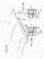
- the Figure 15A shows a body component K in the form of a car roof cladding with a circumferential folded board.
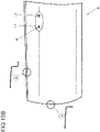
- the Figure 15B shows a body component K in the form of a door outer panel for a motor vehicle door with a recessed grip M in holes L1 and L2 formed therein for the attachment of a door handle.
- Details A and B in the Figure 15B show in section the design of the different edges of the outer door panel including the flanges.
- the conventional sequence of operations in the manufacture of such sheet metal components Figures 15A and 15B consists of drawing, cutting and bending in typically four tools and, if necessary, additionally - in the case of the outer door panel - of embossing and punching. All trimmed edge areas are more or less perpendicular to the working direction of the press device to be used.
- the folded areas are free of undercuts.
- FIG. 5 and 6A to 6G proposes drawing, complete trimming and all-round folding in a further developed (overall) composite tool W, ie the entire manufacturing process of the body component K takes place in the composite tool W.
- a possible further development aims at slightly different component geometries with flared flanges KF according to figure 8 away. It includes drawing, complete trimming, folding and post-forming in one tool.
- the reshaping refers to the setting of the flange angle in the closed tool, whereby a targeted compensation of the elastic angle deflection when opening the tool is achieved.
- Figures 10A and 10B proposes drawing, complete trimming, folding and embossing in a composite tool W, with flared flange areas KF having embossing P (cf. figure 9 ).
- the embossing operation can be used at the same time to adjust the flange angle (spring-back compensation).
- the figure 11 illustrates the production of multi-stepped rims using the compound tool W.
- the composite tool W shown and the method implemented with it provides for drawing, complete trimming, folding, embossing and punching, eg for the production of an outer door panel Figure 15B . Bending is done here on straight and flared flanges. Embossing takes place in the component face; can alternatively or additionally (also) take place in the area of the flange.
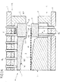
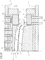
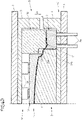
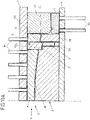
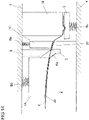
- the composite tool W comprises an upper structure O with a multi-part die 1 and a substructure U with a punch 2 and a sheet metal holder 3 that can be adjusted for this purpose Press and the substructure U are attached to a (press) table 6 of the press.
- the present two-part die 1 has an inner die 1A and an outer die 1B.
- the inner and outer dies 1A, 1B are relative moveable to each other.
- the outer matrix 1B encloses the inner matrix 1A at least in regions.
- the inner die 1A and the outer die 1B are adjustably mounted on an upper part 5 of the superstructure O via (upper air) bolts Bo. These bolts Bo protrude through passage openings 50 of the upper part 5 and thus aligned through openings 70 of a ram 7 of the press which is arranged above the upper part 5 and on which the upper part 5 is fixed. At least one spacer Z is provided on the upper part 5 in the area of the outer matrix 1B. Via this spacer Z, the upper part 5 can act on the outer die 1B during a press stroke along an adjustment direction Vu and cause an adjustment movement of the inner and outer dies 1A, 1B relative to one another.
- the inner die 1A is opposite the stamp 2 of the substructure U, which is immovably fixed to a lower part 4 of the substructure U.
- the lower part 4 in turn rests on the table 6 of the press.
- the stamp 2 forms a stamping surface 20 .
- This punch face 20 faces a die face 10A of the inner die 1A.
- the inner matrix 1A Adjacent to the outer matrix 1B, the inner matrix 1A forms a bending web 11A at the edge. This bending web 11A protrudes in the direction of the punch 2 and corresponds to a peripheral recess 21 on the punch 2.
- a bent edge portion Ka is formed on the body component K.
- This edge section Ka is formed at a separating edge at which a waste piece A is separated from the blank K' by shear cutting.
- the outer die 1B forms a cutting edge 11B and interacts with a sheet metal holder 3 of the substructure U.
- the sheet metal holder 3 is mounted on the substructure U in a translationally adjustable manner and forms a sheet metal holder surface 30 on which the waste piece A of the blank K′ to be separated is placed.
- the punch surface 20, together with the die surface 10A of the inner die 1A, the blank holder surface 30 and an opposite die surface 10B of the outer die 1B, defines a gap R between the punch 2, blank holder 3 and the two-part die 1. In this gap R is the Insert blank K ', and then in one Press stroke to shape and trim the body component K.
- the waste piece A is pressed in between the blank holder surface 30 and the opposite die surface 10B of the outer die 1B and held securely.
- the sheet metal holder 3 and the outer die 1B form a form-fitting area in the form of a groove-like depression 32 and a projection 12B.
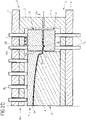
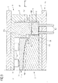
- the composite tool W is open, ie, the space R is accessible and the sheet metal holder 3 is adjusted to a raised insertion position in the direction of the outer die 1B.
- the adjustment of the sheet metal holder 3 along an adjustment direction Vo is controlled via (under-air) bolts Bu. If the blank holder 3 is in its insertion or starting position, the blank holder surface 30 is approximately at the level of the highest point of the stamping surface 20.
- the inner die 1A and the outer die 1B, controlled via the (over-air) bolts Bo, are retracted this far that blank K' can be inserted and comes to rest on the blank holder surface 30 ( Figure 2A ).
- the force of the upper air cushion (ram cushion) defined by the bolts Bo is greater than the force of the lower air cushion (table drawing cushion) defined by the bolts Bu.
- the outer matrix 1B displaces the lower air cushion as the stroke progresses, ie as the upper structure O approaches the lower structure U further along the adjustment direction Vu.
- the pulling process begins.
- the surfaces 110A and 10B of the inner and outer matrices 1A, 1B remain at the same level, since they are each supported against the common upper air cushion via the row of bolts Bo ( Figure 2C ).
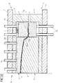
- the body component K is shaped and the drawing process is completed.
- the upper air bolts Bo are pushed into the (press) ram 7 via the inner die 1A.
- the upper air bolts Bo return empty behind the outer die 1B.
- the inner die 1A, the outer die 1B and the blank holder 3 come to a brief standstill until the outer die 1B is seated on the at least one spacer Z ( Figure 2D ).
- the inner die 1A continues to stand still, while the inner die 1A continues to displace the upper air bolts Bo acting on it.
- the outer die 1B is supported via the at least one spacer Z against the upper part 5 and the press ram 7 .
- the outer die 1B moves further downwards in the adjustment direction Vu, relative to the inner die 1A, with the sheet metal holder 7 being displaced.
- the inner die 1A fixes the body component K on the punch 2 and thereby assumes the function of a blank holder.
- the stamp 2 now has the function of a cutting attachment.
- the cutting edge 11B of the outer die 1B performs the function of a cutting blade.
- the cutting edge 11B shears into the sheet material until it breaks through.
- a cutting gap s is determined by a horizontal offset between punch 2 and outer die 1B ( Figure 1A ). This completes the cutting process.
- a drawing edge defined by the waste piece A is severed from the body component K ( Figure 2E ).
- the upper structure O moves with the press ram 7 and the upper part 5 upwards (in the adjustment direction Vo) and takes the inner and outer die 1A, 1B with it. It does not matter whether the upper air is pressurized or depressurized in this phase. Now the body component K and the waste piece A can be removed. This can be done simultaneously or sequentially, manually or mechanized, for example by robot suction spiders. Beneficial for the withdrawal is that the piece of waste that has been cut off comes to rest at a level below the separating edge of the body component (cf. Figure 2E ).
- the lower air with the sheet metal holder 3 only moves up again after the body component K and the waste piece A have been removed, in order to prevent the scrap from colliding with the body component K.
- the loading position starting position
- a new blank K' in the form of a single flat blank can be loaded.
- FIG. 1 , 1A and 2A to 2F and the Figures 3 and 4A to 4E show the component production with tightened board.
- the tightening of the board is necessary to position the drawn and trimmed body part K when Insertion in the subsequent bending tool to ensure.
- edge throwing there may be a risk of what is known as edge throwing.
- the raised edges represent a surface defect of the component along the fold line, which is particularly visible on the painted vehicle and therefore cannot be tolerated.
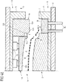
- the process sequence for the production of the body component K is divided here into seven phases, shown on a tool assembly with a counterholder 8 and hold-down device 1C according to FIG Figures 6A to 6G .
- the counter-holder 8 is supported on the lower part 4 via a spring element in the form of a gas pressure spring Gu and is pretensioned in the direction of the upper part 5 .
- the counter-holder 8 is opposite the cutting edge 9 of the upper structure O and is arranged between the punch 2 and a punch attachment 2B.
- the punch attachment 2B is arranged between the sheet metal holder 3 and an insertion area E for the cutting edge 9 of the first structure O.
- the hold-down device 1C is in turn arranged opposite the punch attachment 2B and is located between the cutting edge 9 and the outer die 1B.
- the composite tool W is open.
- the inner die 1A and the hold-down device 1C are supported on the extended bolt Bo of the ram cushion.
- the counter-holder 8 and the blank holder 3 are each in a raised insertion or starting position.
- the blank K' is inserted ( Figure 6A ).
- the plunger 7 with the upper part 5 moves down.
- the outer die 1B sits on the blank holder 3.
- the beads on waste piece A are shaped and the edge of blank K' is clamped between blank holder 3 and outer die 1B ( Figure 6B ).
- the under-air can be switched to zero pressure.
- the free lowering of the sheet metal holder 3 releases the bead.
- the body component K can spring back elastically by a certain amount.
- the body component K is trimmed under less tension, which may have a positive effect on its quality and dimensional accuracy.
- the inner die 1A and the hold-down device 1C displace the ram cushion.
- the cutting edge 9 of the cutting knife engages with the blank K' and performs the trimming.
- the punch attachment 2B and cutting edge 9 can be provided with clearance angles for cutting.
- the board is first bent freely at a certain angle until the counter-holder 8 begins to take effect. From here the cutting knife with the cutting edge 9 acts as a folding strip.
- the cutting blade is preferably provided with a radius (not shown) on its edge facing the die 2 .
- the sheet metal holder 3 is continuously pushed further against the table cushion ( Figure 6D ).
- the superstructure O then moves to its starting position along the opposite adjustment direction Vo.
- the cutting knife with the cutting edge 9 is pulled back one after the other.
- the inner die 1A and the blank holder 1C release the body component K.
- the body component K and the waste piece A can be removed.
- the sheet metal holder 3 initially remains in its lower position, ie, in the design shown, the lower air moves up only with a delay.
- the waste piece A can be gripped from its stable position on the sheet metal holder 3 and the stamp attachment 2B.
- the counter-holder 8 should also only be raised with a delay in order to prevent deformation of the shelf. In the construction shown, this is realized with a controlled gas pressure spring Gu ( Figure 6G ).
- the punch 2 has a defined undercut angle ⁇ in the area of the bent section Ka of the body component K (which forms the bent edge).
- a side wall 22 of the punch 2 thus jumps back by the undercut angle ⁇ in relation to the inner die 1A.
- additional complementary surfaces on the cutting edge 9 and/or the inner die 1A and precise incorporation of the pressure conditions in the composite tool W a targeted overbending of the rim in the closed tool can be achieved. After the elastic springing up when the composite tool W is opened, the rim then assumes the required angular position.
- the holder surface 80 of the counter holder 8 which is inclined at an angle ⁇ relative to the horizontal is also illustrated.
- the inclined holding surface 80 supports the controlled removal of the body part K between the counter-holder 8 and the cutting edge 9.
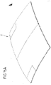
- a further exemplary embodiment relates to the production of sheet metal components with a tongue-shaped flange KF which adjoins the folded rim at least in regions and which, for example, fulfills the function of a joining flange and extends predominantly perpendicularly to the working direction of the press.
- a corresponding body part K is an example in the figure 8 shown.
- a composite tool W is used according to the variant figures 5 and 6A to 6G used, in which case a counter-holder 8 is absolutely necessary. Since the designed rim length is greater overall in the areas of the additional flange KF, the trimming takes place further out.
- the cutting blade with the cutting edge 9 and the counter-holder 8 are made wider by the corresponding amount.
- the counter-holder 8 preferably rests on at least one rigid spacer, which limits the stroke of the counter-holder downwards (in the direction of adjustment Vu).
- the stroke is already over when there is still a sheet metal dimension between the cutting edge 9 and the counterholder 8 that corresponds to the width of the flange KF.
- the cutting edge 9 and the counterholder 8 can have a positive or negative angle ⁇ to the horizontal (see also figure 7 ).
- This angle ⁇ serves to form flanges KF which have a corresponding position in the compound tool W.
- the angle ⁇ is preferably dimensioned in such a way that it compensates for the elastic deflection of the flange when the composite tool W is opened by means of targeted overbending.
- FIG. 9 Joint flanges on a sheet metal component often have additional gradations or embossing P or the like, as in figure 9 is shown as an example.
- embossments P an embossing operation is required. This can be realized with a design variant of the composite tool W, as shown in FIG Figures 10A and 10B is shown.
- the cutting blade with the cutting edge 9 and its cutting strip also assumes the function of a folding strip and, lastly, a shaped strip for embossing.
- a pulling and trimming takes place according to the variant of the figures 5 and 6A to 6G .
- the hold-down device 1C of the upper structure O is again optional.
- the flow of material is preferably controlled by a counterholder 8 in order to ensure error-free shaping.
- the composite tool W and the manufacturing process to be implemented with it are coordinated in such a way that the trimmed or separating edge of the sheet metal leaves the counter-holder 8 shortly before the bottom dead center is reached.
- the stamp outline thus largely corresponds to the contour of the finished body part K.
- the stamp 2 and the cutting edge 9 have mutually opposite and mutually complementary shaped surfaces which correspond to the geometry of the issued board on the body part K.
- the forming surface 210 of the recess 21 opposite a first cutting edge section 90a has 2 steps for producing the embossing P on the punch.
- the holder surface 80 of the counter holder 8 and the complementary surface of a second cutting edge section 90b opposite this holder surface 80, which runs at an obtuse angle to the surface of the first cutting edge section 90a are largely flat ( Figure 10B ).
- the area between the cutting edge 9 and the punch 2 is again advantageously inclined by the angle ⁇ (cf. 7 ) in relation to the horizontal in order to form appropriate layers of the exhibited shelf or to bring in targeted overbends.
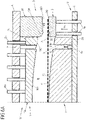
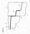
- FIG. 11 As in the sectional view of figure 11 is shown, the production of multi-stepped rims with a compound tool W is also possible.
- adjacent cutting edge sections 90a, 90b of the cutting edge 9 are stepped for this purpose, so that one cutting edge section 90b projects in the adjustment direction Vu in relation to the other cutting edge section 90a.
- the counter-holder 8 opposite the blade 9 accordingly has a holder surface 80 that is complementary to the blade sections 90a, 90b, so that a between the cutting edge 9 and the counter-holder 8 at the end of the press stroke formed board is stepped several times.
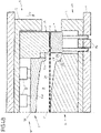
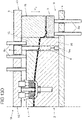
- One with the figures 12 and 13A to 13G shown variant of a composite tool W is based on the variant of the figures 5 and 6A to 6G and provides for the formation of a trough-shaped embossing in the component surface by means of an (embossing) insert 16 on the upper structure O during the cutting and folding in the edge area.
- the insert 16 is mounted on the upper part 5 so that it can be adjusted elastically relative to the inner matrix 1A.
- the elastic mounting is implemented via a number of spring elements F1, F2, via which the insert 16 is supported on the upper part 5.
- the production of the embossing on the body part - here, for example, in the form of a recessed grip M corresponding to the Figure 15B - is also realized in the press stroke and accomplished without additional adjustment drives.
- an embossing depression 201 of the stamp 2 formed in the stamp surface 20 is opposite the insert 16 .
- the insert 16 can dip into this embossing depression 201 when the inner die 1A and the punch 2 are
- a punch 17 rigidly fixed to the upper part 5 is guided on the insert 16 .
- the insert 16 is displaced against the spring elements F1, F2 in the upper part 5 with further adjustment of the upper part 5 in adjustment Vu and thus in a further, second adjustment phase.
- the punch 17 engages and punches the body component K as the adjustment continues, with the insert 16 taking on the function of a hold-down device.
- Perforation waste LA resulting from the perforation is disposed of via an opening in the embossing trough 201 , into which the punch 17 dips and which opens into a scrap channel 2010 .
- embossings in the type of recessed grip M in a drawing stage by means of a correspondingly contoured die and a correspondingly contoured punch. Unrest, waviness, raised edges, flat or sinking points on or around the recessed grip M, which represent intolerable surface defects on the body part, are often the result. Therefore, such embossings are often formed in subsequent operations with different hold-down and mold inserts.
- the proposed variant of the figures 12 and 13A to 13G facilitates the achievement of a component surface of high quality, since during the Shaping of the recessed grip M through the insert 16 of the sheet metal blank K' is still under biaxial tensile stress from the drawing and is held between the punch 2 and the inner die 1A. This tensile stress is superimposed on the states of stress that arise as a result of the embossing process in and around the recessed grip M and reduces the influence of the different processing lengths over the recessed grip M.
- holes can also be introduced independently of an embossing function, in that the punch 17 is guided in the inner die 1A.
- the inner die 1A then assumes the function of a hold-down device in the second adjustment phase for the perforation.
- embossing and/or punching that deviates from the working direction of the press is also possible if appropriate drives are used for the embossing and/or cutting elements be provided.
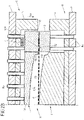
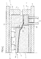
- the figure 14 also schematically illustrates a development of a composite tool W of figure 5 with punch attachment 2B integrated in punch 2.
- the punch attachment 2B is only separated from the punch surface 20 of the punch 2, which interacts with the inner die 1A, via the insertion area E for the cutting edge 9.
- the punch attachment 2B interacting with the separate hold-down device 1C of the upper part 5 is not spatially separated from the punch 2 as in the previously explained variants, but is part of the punch 2.
- An integration of the punch attachment 2B in the punch 2 is of course also included the previously explained variants possible.
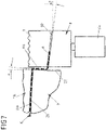
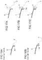
- the cutting edge 900 of the cutting strip thus has first cutting edge sections 900A, second cutting edge sections 900B and transition regions 901 located in between.
- first cutting edge sections 900A are each on the inside and the second cutting edge section 900B is on the outside, so that the first cutting edge sections 900A form an inner contour of the cutting edge 900 and the second cutting edge section 900B an outer contour of the Cutting edge 900 are defined. 1.
- the second cutting edge section 900B of the cutting edge 900 which defines the outer contour, thus protrudes here in relation to the first cutting edge section 900A, which defines the inner contour, so that when the die 1 and the punch 2 are pressed against one another, the cutting edge 9 first cuts its cutting edge 900 by means of the second cutting edge section 900B a second (subsequently bevelled) edge region II, before the cutting edge 9 carries out a trimming in the first edge regions I by means of the first cutting edge section 900A of its cutting edge 900.
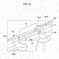
- a counter-holder 8 which is at least partially complementary to the cutting edge 9, is provided in the (tool) lower part 4, which in the plan view of FIG figure 20 is shown.
- This counterholder 8 is in its upper position during the trimming of the second edge areas II and the transitional edge areas III and acts as a counterknife in the transitional edge area III.
- uncontrolled tearing in the transitional edge region III is limited to a minimum length or even completely prevented.
- the cutting edge 9 sits in the first edge area I on the counterholder 8 and begins to displace it downwards (in the adjustment direction Vu) against a defined force as the press stroke progresses.
- the possibility of using a separate counterholder 8 in the area of the fold is unaffected if this is opportune for the component and/or the process.
- the counter-holder 8 for cutting and the counter-holder 8 for folding can also be made in one piece with a corresponding structural design and/or be supported against the same pressure elements in the lower part 4 .
- a counter-holder 8 is used from the outset for folding in the second edge area II, its contour in the transitional edge area III can also be designed as a bottom cutter. In this case, the trimming is carried out in advance in the first edge area I and then peels over the transition edge area III. Finally, the second edge area II is then cut and folded.
- the described function and tool design do not necessarily imply full-edged cutting in the first and second edge regions I and II.
- Crossing or peeling cutting can also be provided here as required.
- a cutting insert is provided on the upper or lower blade in the transition area 901 . Its cutting edge then protrudes by a distance of 0.5 mm to 3.0 mm compared to those of the cutting bar(s) in edge areas I and II. The cutting insert cuts into the transition edge region III and is then displaced so far that its cutting edge is at the same level as that of the first and second edge regions I and II. Then, the cutting edge portions 900A, 900B are engaged in the first and second edge portions I and II.
Description
Die Erfindung betrifft ein Verbundwerkzeug nach dem Oberbegriff des Anspruchs 1 sowie ein Herstellungsverfahren nach dem Oberbegriff des Anspruchs 15. Ein derartiges Verbundwerkzeug und ein entsprechendes Herstellungsverfahren sind aus der
Verbundwerkzeuge und insbesondere Gesamtverbundwerkzeuge sind üblicherweise dadurch charakterisiert, dass mindestens zwei technologisch verschiedene Bearbeitungsverfahren in einem Werkzeug und in einem Pressenhub durchgeführt werden. Mit anderen Worten werden mehrere Operationen oder Funktionen in einem Werkzeug oder Bearbeitungsschritt integriert. Gemeinhin werden Verbundwerkzeuge bisher überwiegend für geometrisch einfache Bauteile eingesetzt, die in der Regel aus einem Blechstreifen gefertigt werden. In der Herstellung großer, komplexer Blechbauteile, z.B. Karosseriebauteilen, aus Blechrohlingen, z.B. in Form von Einzelplatinen, ist der Einsatz von Gesamtverbundwerkzeugen nicht gebräuchlich.Composite tools and in particular complete composite tools are usually characterized in that at least two technologically different machining processes are carried out in one tool and in one press stroke. In other words, multiple operations or functions are integrated into one tool or machining step. In general, composite tools have so far mainly been used for geometrically simple components, which are usually made from a sheet metal strip. In the manufacture of large, complex sheet metal components, e.g.
Karosserieblechteile werden in der Regel in einer Operationsfolge von Ziehen, Beschneiden, Lochen und Fertigformen in mehreren Werkzeugen oder Werkzeugstufen hergestellt. Das Fertigformen kann insbesondere eine Abkant-Operation darstellen. Typischerweise stellt das Ziehen der Bauteil-Grundform aus einem ebenen Blechrohling die erste Operation im Herstellungsprozess mit Linien- oder Transferwerkzeugen dar.Body panel parts are typically manufactured in a sequence of operations of drawing, trimming, piercing and final forming in multiple tools or tooling stages. The finish forming can in particular represent a bending operation. Typically, drawing the basic component shape from a flat sheet metal blank is the first operation in the manufacturing process with line or transfer tools.
Das Ziehen ist typischerweise ein Tiefzieh-, Streckzieh- oder kombinierter Vorgang in einem Werkzeug. Anschließend, in vom Ziehen getrennten Operationen, erfolgen die weiteren Schritte wie Lochen, Schneiden und Fertigformen.Drawing is typically a deep-drawing, stretch-drawing or a combined process in one tool. Then, in operations that are separate from drawing, further steps such as punching, cutting and final shaping take place.
Die häufigsten Schneidprozesse an Karosserieblechteilen sind z.B. Scherschneidprozesse:
- Lochen: Zur Erzeugung einer geschlossenen Innenkontur am Werkstück
- Beschneiden: Hierbei wird der äußere Ziehrand abgeschnitten, um die Außenkontur des Bauteils zu erzeugen, bzw. eine vorläufige Außenkontur, die in einer nachfolgenden Operation weiter bearbeitet wird.
- Weitere Schneidprozesse ohne Bedeutung für die vorliegende Erfindung sind z.B. das Einschneiden oder Ausklinken.
- Punching: To create a closed inner contour on the workpiece
- Cropping: Here, the outer drawing edge is cut off in order to create the outer contour of the component, or a preliminary outer contour that is further processed in a subsequent operation.
- Other cutting processes that are irrelevant to the present invention are, for example, notching or notching.
Unter Nach- oder Fertigformen werden ferner formgebende Operationen zumeist in der letzten Werkzeugstufe verstanden. Ein Prozess des Nach- oder Fertigformens stellt das Abkanten dar. Dabei wird der Rand des gezogenen und beschnittenen Blechteils um etwa 90° "umgebogen". Abgekantete Borde an Blechteilen dienen z.B. als Fügeflansche oder als Vorform für eine Bördel- oder Rollfalzoperation im Rohbau, wo das Einzelteil mit weiteren zu einem Zusammenbau gefügt wird. Zumeist erfolgt das Abkanten in der letzten Operation.Post-forming or final forming are also understood to mean shaping operations, mostly in the last tool stage. Bending is a process of reshaping or finishing. The edge of the drawn and trimmed sheet metal part is "bent" by about 90°. Folded rims on sheet metal parts are used, for example, as joining flanges or as a preform for a flanging or roll hemming operation in the body shell, where the individual part is joined with others to form an assembly. In most cases, the bending is done in the last operation.
Die
Weitere Varianten des Nach- oder Fertigformens sind z.B. das Nachschlagen oder Kalibrieren. Dabei wird bereichsweise auf ein bereits geformtes Bauteil eingewirkt, um dessen Geometrie lokal zu beeinflussen. Hierbei werden z.B. Verprägungen eingebracht oder Radien verkleinert.Further variants of post-forming or final forming are, for example, refacing or calibrating. In this case, a component that has already been formed is acted on in certain areas in order to influence its geometry locally. Here, for example, embossings are introduced or radii are reduced.
Bekannt ist ferner die Kombination aus Beschneiden und Abkanten in einem Folgewerkzeug an einem in einem ersten Werkzeug gezogenen Bauteil, wobei das Schneidmesser (mit einer Schneidleiste) gleichzeitig als Abkantleiste dient. Dies ist schematisch dargestellt in den
Ausgehend von dem vorstehend diskutierten Stand der Technik liegt der Erfindung die Aufgabe zugrunde, eine Reduzierung der Gesamtzahl der zur Fertigung eines Blechbauteils erforderlichen Werkzeuge und hierüber eine Reduzierung der Betriebsmittelkosten sowie der Entwicklungs- und Beschaffungszeiten zu erreichen und Prozessketten zu verkürzen.Proceeding from the prior art discussed above, the invention is based on the object of reducing the total number of tools required to manufacture a sheet metal component and thereby reducing operating costs and development and procurement times and shortening process chains.
Diese Aufgabe wird mit einem Verbundwerkzeug des Anspruchs 1 gelöst als auch mit einem Herstellungsverfahren des Anspruchs 15 gelöst.This object is achieved with a composite tool of
Gemäß einem ersten Aspekt der Erfindung ist ein Verbundwerkzeug zur Herstellung eines flächigen Blechbauteils mit einer eine Ziehmatrize (im Folgenden auch kurz: "Matrize") aufweisenden ersten Struktur und einer einen Ziehstempel (im Folgenden auch kurz: "Stempel") aufweisenden zweiten Struktur vorgeschlagen. Wenigstens die erste Struktur oder die zweite Struktur ist zumindest teilweise translatorisch verstellbar, um die Matrize und den Stempel gegeneinander zu pressen und hierdurch das Blechbauteil aus einem zwischen der Matrize und dem Stempel befindlichen und als Einzelplatine ausgebildeten Blechrohling durch Ziehen, d.h., durch einen Ziehvorgang und Herstellung eines Ziehteils, auszuformen. Hierfür ist an der zweiten Struktur zusätzlich zu dem Stempel wenigstens ein relativ zu dem Stempel translatorisch verstellbarer Blechhalter vorgesehen. Des Weiteren ist erfindungsgemäß vorgesehen, dass
- die Matrize der ersten Struktur wenigstens zweiteilig, mit einer inneren Matrize und einer äußeren Matrize ausgeführt ist, wobei die innere Matrize und die äußere Matrize an der ersten Struktur relativ zueinander verstellbar sind, und
- die äußere Matrize und der relativ zu dem Stempel translatorisch verstellbare Blechhalter einander gegenüberliegen und eingerichtet sind, beim Pressen der zweiteiligen Matrize und des Stempels gegeneinander zwischen sich ein Abfallstück des Blechrohlings zu halten, das mit dem Pressen der Matrize und des Stempels gegeneinander an einem äußeren Rand des gezogenen Blechrohlings - respektive des aus dem Blechrohling hergestellten Ziehteils - abgetrennt wird.
- the die of the first structure is designed in at least two parts, with an inner die and an outer die, the inner die and the outer die being adjustable relative to one another on the first structure, and
- the outer die and the sheet metal holder, which is translationally adjustable relative to the punch, are opposite one another and are set up to hold a waste piece of the sheet metal blank between them when the two-part die and the punch are pressed against each other, which with the pressing of the die and the punch against each other at an outer edge of the drawn sheet metal blank - or the drawn part produced from the sheet metal blank - is separated.
Derart erfolgt beim Pressen der wenigstens zweiteiligen Matrize und des Stempels gegeneinander zusätzlich zu dem Ziehen des Blechrohlings (in einer ersten Verstellphase der ersten und zweiten Strukturen) ein randseitiges Beschneiden (in wenigstens einer nachfolgenden zweiten Verstellphase). Der translatorisch verstellbare Blechhalter sichert hierbei im Zusammenspiel mit der wenigstens zweiteiligen Matrize die definierte Position und Ausrichtung des abzutrennenden Abfallstücks und gewährleistet durch seine Verstellbarkeit relativ zu dem Stempel die Integration einer Beschneidungsoperation in den Pressenhub. Unter einem "Pressen der zweiteiligen Matrize und des Stempels gegeneinander" wird im Folgenden insbesondere verstanden, dass die zweiteilige Matrize und der Stempel unter der Einwirkung einer von einer (mit dem Verbundwerkzeug gerüsteten) Presse aufgebrachten Verstellkraft aufeinander zu verlagert werden und eine eigentliche Pressung zumindest eines Teils der wenigstens zweiteiligen Matrize gegen den Stempel erst mit einem zeitlichen Ende des Ziehvorgangs erfolgt. "Beim Pressen der zweiteiligen Matrize und des Stempels gegeneinander" und damit einhergehend mit der Verlagerung für die eigentliche, spätere Pressung von (Zieh-) Matrize und (Zieh-) Stempel wird z.B. zunächst nur die äußere Matrize gegen den Blechhalter - im eigentlichen Sinne - "gepresst". So ist insbesondere eingeschlossen, dass während des gesamten Ziehvorgangs die äußere Matrize gegen den Blechhalter gepresst wird und eine Pressung der inneren Matrize gegen den Stempel erst mit dem Ende des Ziehvorgangs erfolgt.In this way, when the at least two-part die and the punch are pressed against each other, in addition to the drawing of the sheet metal blank (in a first Adjustment phase of the first and second structures) an edge trimming (in at least one subsequent second adjustment phase). The translationally adjustable blank holder, in cooperation with the at least two-part die, ensures the defined position and alignment of the waste piece to be separated and, thanks to its adjustability relative to the punch, ensures the integration of a trimming operation in the press stroke. In the following, "pressing the two-part die and the punch against each other" means in particular that the two-part die and the punch are displaced towards one another under the action of an adjustment force applied by a press (equipped with the composite tool) and an actual pressing of at least one Part of the at least two-part die against the punch only takes place at the end of the drawing process. "When pressing the two-part die and the punch against each other" and thus associated with the shift for the actual, later pressing of (drawing) die and (drawing) punch, for example, initially only the outer die against the blank holder - in the actual sense - "pressed". In particular, this includes the fact that the outer die is pressed against the blank holder during the entire drawing process and that the inner die is only pressed against the punch at the end of the drawing process.
Dass die innere Matrize und die äußere Matrizen an der ersten Struktur relativ zueinander verstellbar sind, schließt sowohl ein, dass die innere Matrize relativ zu der äußeren Matrize verstellbar ist, als auch, dass die äußere Matrize relativ zu der inneren Matrize verstellbar ist. Durch die Verstellbarkeit der inneren und äußeren Matrizen relativ zueinander an der ersten Struktur sowie durch das Zusammenwirken mit dem verstellbaren Blechhalter der zweiten Struktur kann über den Pressenhub besonders einfach ein Abtrennen des Abfallstücks realisiert werden. Grundsätzlich kann dabei die äußere Matrize der ersten Struktur die innere Matrize zumindest teilweise umschließen.That the inner die and the outer die are adjustable relative to each other on the first structure includes both the inner die being adjustable relative to the outer die and the outer die being adjustable relative to the inner die. Due to the adjustability of the inner and outer dies relative to each other on the first structure and the interaction with the adjustable sheet metal holder of the second structure, the waste piece can be separated particularly easily via the press stroke. In principle, the outer matrix of the first structure can at least partially enclose the inner matrix.
In einer Ausführungsvariante weist die äußere Matrize einen ersten Formschlussbereich auf und der Blechhalter weist einen zweiten Formschlussbereich auf. Über die ersten und zweiten Formschlussbereiche der äußeren Matrize und des Blechhalters wird das Abfallstück des Blechrohlings beim Pressen (lokal) verformt, sodass zumindest ein Bereich des Abfallstücks formschlüssig in wenigstens einen der ersten und zweiten Formschlussbereiche greift und/oder wenigstens einer der ersten und zweiten Formschlussbereiche in das Abfallstück formschlüssig eingreift. Die ersten und zweiten Formschlussbereiche können somit der Fixierung des Abfallstücks zwischen dem Blechhalter und der äußeren Matrize beim Pressen dienen, gleichwohl dies nicht zwingend ist. Die ersten und zweiten Formschlussbereiche können beispielsweise als Vorsprünge und/oder Vertiefungen ausgebildet sein. Beispielsweise ist eine Auswölbung an der äußeren Matrize zur Herstellung einer hiermit korrespondierenden Sicke am Abfallstück des Blechrohlings vorgesehen.In one embodiment variant, the outer die has a first form-fitting area and the sheet metal holder has a second form-fitting area. The waste piece of the sheet metal blank is (locally) deformed during pressing via the first and second form-fitting areas of the outer die and the blank holder, so that at least one area of the waste piece engages in at least one of the first and second form-fitting areas and/or at least one of the first and second form-fitting areas positively engages in the piece of waste. The first and second form-fitting areas can thus serve to fix the waste piece between the sheet metal holder and the outer die during pressing, although this is not the case is mandatory. The first and second form-fitting areas can be formed, for example, as projections and/or indentations. For example, a bulge is provided on the outer die to produce a corresponding bead on the waste piece of the sheet metal blank.
Das Verbundwerkzeug ist somit eingerichtet, eine zum Umformen des Blechrohlings aufgebrachte Presskraft gleichzeitig dazu zu nutzen, einen äußeren Rand des Blechrohlings als Abfallstück abzutrennen und damit den Blechrohling zu beschneiden. Ggf. wird auch gleich der Rand des Blechbauteils fertiggeformt, zumindest aber umgeformt. In einem Pressenhub erfolgt somit zusätzlich zu einem Umformen ein Beschneiden und z.B. ein randseitiges Umbiegen oder Abkanten. Die erste Struktur und die zweite Struktur können folglich nicht nur eingerichtet sein, mit dem Pressen der Matrize und des Stempels gegeneinander auch einen äußeren Rand des Blechrohlings als Abfallstück abzutrennen. Vielmehr können die erste Struktur und die zweite Struktur auch eingerichtet sein, einen Randabschnitt des Blechbauteils, an dem ein durch das Abtrennen des Abfallstücks entstehender Trennrand vorliegt, vor oder nach dem Abtrennen des Abfallstücks umzuformen. In diesem Zusammenhang kann insbesondere vorgesehen sein, dass mit dem Pressen der Matrize und des Stempels gegeneinander der Randabschnitt des Blechbauteils, an dem der Trennrand vorliegt, vor dem Abtrennen des Abfallstücks gebogen oder nach dem Abtrennen des Abfallstücks abgekantet wird. Hierbei stellt dann eine Presse, auf der das Verbundwerkzeug mit den ersten und zweiten Strukturen gerüstet ist, den alleinigen Antrieb für alle Werkzeugfunktionen dar, d.h. es sind keine weiteren hydraulischen oder anderweitigen Aktuatoren eingesetzt, um das Beschneiden und Fertigformen zu realisieren.The composite tool is thus set up to simultaneously use a pressing force applied for forming the sheet metal blank to separate an outer edge of the sheet metal blank as a waste piece and thus to trim the sheet metal blank. If necessary, the edge of the sheet metal component is also finish-formed, or at least reshaped. In one press stroke, in addition to forming, trimming and e.g. edge bending or folding takes place. The first structure and the second structure can consequently not only be set up to also separate an outer edge of the sheet metal blank as a waste piece when the die and the punch are pressed against one another. Rather, the first structure and the second structure can also be set up to reshape an edge section of the sheet metal component, on which there is a separating edge resulting from the cutting off of the waste piece, before or after the cutting off of the waste piece. In this context, it can be provided that with the pressing of the die and the punch against each other, the edge section of the sheet metal component on which the separating edge is present is bent before the waste piece is cut off or folded after the waste piece is cut off. In this case, a press on which the composite tool is set up with the first and second structures represents the sole drive for all tool functions, i.e. no further hydraulic or other actuators are used to implement the trimming and final forming.
Bei einem erfindungsgemäßen Verbundwerkzeug kann über die relativ zueinander verstellbaren inneren und äußeren Matrizen mindestens eine Folgeoperation im Ziehwerkzeug integriert werden. Hierbei ist zumindest ein äußeres Beschneiden des Blechbauteils in die Ziehstufe integriert. Dabei kann es sich insbesondere um ein umlaufendes Beschneiden, mithin einen Komplettbeschnitt, handeln. Denkbar ist aber auch, nur einen ersten Segmentbeschnitt im Ziehwerkzeug durchzuführen, was z.B. beim Sonderfall eines Ziehens mit offenen Köpfen realisierbar wäre. Das Ziehen und das Beschneiden erfolgen dabei grundsätzlich in einem durchgehenden Hub des Verbundwerkzeugs. Die erzeugte Trenn- oder Beschnittkante kann sowohl die Kontur des Fertigteils darstellen, als auch in weiteren Operationen, z.B. einem Abkanten oder Nachformen, weiter bearbeitet werden.In a composite tool according to the invention, at least one subsequent operation can be integrated in the drawing tool via the inner and outer matrices that can be adjusted relative to one another. Here, at least one external trimming of the sheet metal component is integrated into the drawing stage. This can in particular be a circumferential trimming, and therefore a complete trimming. However, it is also conceivable to carry out only a first segment trimming in the drawing tool, which could be realized, for example, in the special case of drawing with open heads. In principle, the pulling and the trimming take place in a continuous stroke of the composite tool. The created separating or trimming edge can represent the contour of the finished part as well as be further processed in further operations, eg bending or reshaping.
Das erfindungsgemäße Verbundwerkzeug ermöglicht es, die Anzahl der Werkzeuge für die Herstellung eines Blechbauteils um mindestens eine Operation zu reduzieren. Die Erfindung ist hierbei z.B. nicht auf Karosseriebauteile für Kraftfahrzeuge beschränkt, sondern erstreckt sich auch auf die Fertigung anderer flächiger Blechbauteile, insbesondere Blechbauteile aus Stahl, Aluminium oder anderen Werkstoffen.The composite tool according to the invention makes it possible to reduce the number of tools for the production of a sheet metal component by at least one operation. The invention is not limited to body components for motor vehicles, for example, but also extends to the production of other flat sheet metal components, in particular sheet metal components made of steel, aluminum or other materials.
Die Integration eines randseitigen Beschneidens des Blechrohlings ist dabei auch zu trennen von dem Setzen eines Entlastungsschlitzes in einem inneren Abfallbereich des Bauteils, z.B. in einer Fensteröffnung. Ein solcher Entlastungsschnitt wird während der Umformung aufgezogen, wodurch der Materialfluss von "innen nach außen" begünstigt wird. Dabei handelt es sich jedoch nur um einen linienförmigen Schnitt, d.h. keine Beschnittoperation. Es entsteht in dieser Operation kein Abfallstück, das aus dem Werkzeug abgeführt werden müsste. Der Bereich des aufgezogenen Entlastungsschnitts wird erst in einer nachgelagerten Operation ausgeschnitten. Folglich handelt es sich nicht um die Integration einer Beschnittoperation in das Ziehwerkzeug.The integration of edge trimming of the sheet metal blank must also be separated from the setting of a relief slot in an inner waste area of the component, e.g. in a window opening. Such a relief cut is made during the forming, which promotes the material flow from "inside to outside". However, this is only a line-shaped cut, i.e. no trimming operation. This operation does not produce any waste that would have to be removed from the tool. The area of the relief incision made is only cut out in a subsequent operation. Consequently, it is not a matter of integrating a crop operation into the drawing tool.
Ebenfalls bekannt ist, innere Entlastungsschnitte oder -löcher bereits beim Zuschneiden eines Blechrohlings einzubringen. Auch hier handelt es sich nicht um die Integration einer Beschnittoperation in das Ziehwerkzeug. Ebenfalls bekannt ist, dass im Ziehwerkzeug Lochstempel verbaut werden. Diese dienen dazu, Löcher im Abfallbereich des Bauteils zu schneiden, die zur Zentrierung des Ziehteils in der nachfolgenden Operation dienen. Auch hier handelt es sich nicht um die Integration einer Beschnittoperation in das Ziehwerkzeug, wie es die vorgeschlagene Lösung vorsieht.It is also known to make internal relief cuts or holes when cutting a sheet metal blank. Again, this is not about integrating a crop operation into the drag tool. It is also known that punches are installed in the drawing tool. These are used to cut holes in the waste area of the component, which are used to center the drawn part in the subsequent operation. Again, it is not a matter of integrating a trimming operation into the drawing tool, as the proposed solution envisages.
In einer Ausführungsvariante integriert das Verbundwerkzeug einen umlaufenden äußeren Bauteilbeschnitts in der Ziehstufe. Weitere Operationen können in möglichen Weiterbildungen in die Ziehstufe zu integriert sein. Dabei handelt es sich z.B. um die Integration von Ziehen, Schneiden und Abkanten oder Ziehen, Schneiden, Abkanten und Prägen. Hierdurch ist es beispielsweise möglich, die gesamte Fertigungsfolge eines Blechbauteils in dem Verbundwerkzeug und in einem damit umgesetzten Pressenhub zu realisieren.In one embodiment variant, the composite tool integrates a circumferential outer component trimming in the drawing stage. Further operations can be integrated into the drawing stage in possible further developments. This involves, for example, the integration of drawing, cutting and edging or drawing, cutting, edging and embossing. This makes it possible, for example, to realize the entire production sequence of a sheet metal component in the composite tool and in a press stroke implemented with it.
Die vorgeschlagene Lösung unterscheidet sich dabei auch von Folgeverbundwerkzeugen, die dadurch charakterisiert sind, dass die Fertigung der Bauteile aus einem Blechstreifen (vom Coil) erfolgt, der schrittweise durch eine Abfolge von mehreren Werkzeugstufen geschoben oder gezogen wird. Das fertige Bauteil wird erst in der letzten Stufe vom Streifen getrennt. Mit Folgeverbundwerkzeugen werden in der Regel nur kleine bis mittelgroße, geometrisch einfache Bauteile in hohen Stückzahlen gefertigt. Mit der vorgeschlagenen Lösung ist es demgegenüber möglich, dass große, komplexe Blechbauteile aus einem flächigen Blechrohling (in der Form einer Einzelplatine) herstellbar sind, wobei eine Umformoperation dem Bauteilbeschnitt zeitlich vorangestellt ist.The proposed solution also differs from progressive dies, which are characterized in that the components are manufactured from a sheet metal strip (from a coil) that is pushed or pulled step by step through a sequence of several tool stages. The finished component is only separated from the strip in the last stage. With progressive dies, in usually only small to medium-sized, geometrically simple components are manufactured in large quantities. In contrast, with the proposed solution, it is possible for large, complex sheet metal components to be produced from a flat sheet metal blank (in the form of a single blank), with a forming operation preceding the trimming of the component.
Das Verbundwerkzeug bildet hierbei typischerweise ein bauteilspezifisches Presswerkzeug, in dem ein Blechrohling global umgeformt wird. Hierbei folgt ein Abtrennen, vorzugsweise ein Scherschneiden am Umfang der dreidimensional geformten Geometrie, kein Laser- oder Wasserstrahlschneiden in der Horizontalebene. Darüber hinaus wird das Blechbauteil nicht ausgeschnitten, sondern ein Abfallstück vom Blechrohling abgeschnitten.The composite tool typically forms a component-specific pressing tool in which a sheet metal blank is formed globally. This is followed by severing, preferably shearing at the periphery of the three-dimensionally shaped geometry, no laser or water jet cutting in the horizontal plane. In addition, the sheet metal component is not cut out, but a waste piece is cut off from the sheet metal blank.
Alternativ oder ergänzend ist in einer Ausführungsvariante der Blechhalter an der zweiten Struktur relativ zu dem Stempel in eine Einlegeposition auf die äußere Matrize zu verstellbar. In der dann eingenommenen Einlegeposition ist der Blechrohling mit einem randseitigen Abschnitt auf dem Blechhalter anzuordnen. Beim anschließenden Pressen der Matrize und des Stempels gegeneinander ist der Blechhalter relativ zu dem Stempel in eine zu der Einlegeposition verschiedene Halteposition verstellbar, in der das von dem Blechrohling abgetrennte Abfallstück zwischen der äußeren Matrize und dem Blechhalter gehalten ist. Beispielsweise wird der Blechhalter aus der Einlegeposition unter Einwirkung der ersten Struktur und insbesondere der mit der ersten Struktur verstellten äußeren Matrize verlagert. Das zwischen der äußeren Matrize und dem verstellbaren Blechhalter vorgesehene Abfallstück des Blechrohlings wird hierbei gegebenenfalls definiert umgeformt. In jedem Fall wird durch den relativ zu dem Stempel verstellbaren Blechhalter das abgetrennte Abfallstück am Ende des Pressenhubes in einer definierten Position gehalten und kann relativ zu dem fertiggestellten Blechbauteil verlagert werden. Dies ist insbesondere mit Blick auf das Abführen des Abfallstücks aus dem Verbundwerkzeug von Vorteil.Alternatively or additionally, in one embodiment variant, the sheet metal holder on the second structure can be adjusted relative to the stamp into an insertion position onto the outer die. In the insertion position then assumed, the sheet metal blank is to be arranged with an edge section on the sheet metal holder. During the subsequent pressing of the die and the punch against each other, the blank holder can be adjusted relative to the punch into a holding position different from the insertion position, in which the waste piece separated from the sheet metal blank is held between the outer die and the blank holder. For example, the sheet metal holder is displaced from the insertion position under the influence of the first structure and in particular of the outer die adjusted with the first structure. The waste piece of the sheet metal blank provided between the outer die and the adjustable sheet metal holder is optionally reshaped in a defined manner. In any case, the separated piece of scrap is held in a defined position at the end of the press stroke by the sheet metal holder, which can be adjusted relative to the stamp, and can be displaced relative to the finished sheet metal component. This is particularly advantageous with a view to removing the waste piece from the composite tool.
Wie bereits obig ausgeführt, ist das vorgeschlagene Verbundwerkzeug eingerichtet, eine zum Umformen des Blechrohlings aufgebrachte Presskraft und damit den Pressenhub gleichzeitig auch dazu zu nutzen, das Abfallstück abzutrennen und ggf. den Rand des Blechbauteils fertigzuformen. Dementsprechend können dann auch in einer Ausführungsvariante durch die translatorische Verstellung der ersten Struktur und der zweiten Struktur aufeinander zu der Blechhalter relativ zu dem Stempel und/oder die inneren und äußeren Matrizen relativ zueinander verstellt werden. Der Blechhalter ist somit beispielsweise während des Pressenhubes relativ zu dem Stempel nicht fremdkraftbetätigt durch einen zusätzlichen Antrieb verstellbar, sondern allein durch die Pressenkraft. Eine Relativbewegung des Blechhalters zu dem Stempel wird somit allein durch die Verstellung der ersten und zweiten Strukturen aufeinander zu und den damit realisierten Pressenhub verursacht. Ein zusätzlicher (motorischer) Verstellantrieb ist hierfür nicht vorgesehen. Gleiches gilt für die alternativ oder ergänzend vorgesehene Verstellung innerer und äußerer Matrizen relativ zueinander während des Pressens.As already explained above, the proposed composite tool is set up to use a pressing force applied for forming the sheet metal blank and thus the press stroke at the same time to separate the waste piece and, if necessary, to finish-form the edge of the sheet metal component. Accordingly, then in one embodiment by the translational adjustment of the first structure and the second structure on each other to the sheet metal holder relative to the punch and / or inner and outer matrices are adjusted relative to each other. The blank holder is thus, for example, during the press stroke relative to the ram not externally operated by an additional drive adjustable, but only by the press force. A movement of the sheet metal holder relative to the punch is thus caused solely by the adjustment of the first and second structures toward one another and the press stroke thus implemented. An additional (motorized) adjustment drive is not provided for this. The same applies to the alternatively or additionally provided adjustment of inner and outer matrices relative to each other during pressing.
An der zweiten Struktur ist zusätzlich eine Stempelankonstruktion vorgesehen, die zwischen dem Blechhalter und einem Einführbereich für eine Schneide der ersten Struktur angeordnet ist. Durch das Vorsehen einer zusätzlichen Stempelankonstruktion kann beispielsweise eine Gestaltung einer Ziehschale in dem Verbundwerkzeug mit einer offenwinkligen Zarge ermöglich werden. Hierdurch kann wiederum eine Ausreckung des Blechrohlings bis in die Bauteilmitte hinein erzielt werden. Dies ist z.B. bei flächigen Außenhautteilen, wie Dächern oder Türaußenblechen, als herzustellenden (Karosserie-) Blechbauteilen erforderlich. Die Stempelankonstruktion liegt benachbart zu einem Bereich der zweiten Struktur, dem Einführbereich, vor, in den eine für das Beschneiden des Blechrohlings vorgesehene Schneide der zweiten Struktur beim Pressen eintauchen kann. In einer Ausführungsvariante liegt die Stempelankonstruktion vor diesem Hintergrund einem Niederhalter der ersten Struktur gegenüber. Die Stempelankonstruktion kann in einer Ausführungsvariante zu dem Stempel und andererseits zu dem Blechhalter (quer zu Verstellrichtung des Blechhalters) beabstandet sein. In einer alternativen Ausführungsvariante kann die Stempelkonstruktion aber auch integraler Bestandteil des Stempels sein.A stamp attachment is additionally provided on the second structure, which is arranged between the sheet metal holder and an insertion area for a cutting edge of the first structure. By providing an additional punch attachment, for example, it is possible to design a drawing shell in the composite tool with an open-angled frame. This in turn allows the sheet metal blank to be stretched out into the middle of the component. This is necessary, for example, for flat outer skin parts such as roofs or outer door panels as (body) sheet metal components to be manufactured. The punch attachment is adjacent to an area of the second structure, the insertion area, into which a cutting edge of the second structure provided for cutting the sheet metal blank can dip during pressing. Against this background, in an embodiment variant, the stamp attachment is opposite a hold-down device of the first structure. In one embodiment variant, the punch attachment can be at a distance from the punch and, on the other hand, from the sheet metal holder (transverse to the direction of adjustment of the sheet metal holder). In an alternative embodiment variant, however, the stamp construction can also be an integral part of the stamp.
Grundsätzlich können die erste Struktur und die zweite Struktur des Verbundwerkzeugs eingerichtet sein, mit dem Pressen der Matrize und des Stempels gegeneinander das Abfallstück durch Scherschneiden abzutrennen.In principle, the first structure and the second structure of the composite tool can be set up so that the waste piece can be separated by shear cutting when the die and the punch are pressed against one another.
Bei der erfindungsgemäß vorgeschlagenen wenigstens zweiteilig ausgeführten Matrize, bei der eine innere Matrize und eine äußere Matrize relativ zueinander verstellbar sind, kann in einer Variante für das Abtrennen des Abfallstücks an der äußeren Matrize eine Schneidkante ausgebildet oder eine Schneide montiert sein. Im zuerst genannten Fall bildet eine an die innere Matrize angrenzende Kante der äußeren Matrize eine Schneidkante für das Abtrennen des Abfallstücks. Die äußere Matrize wird hier (gegebenenfalls zusammen mit dem gegenüberliegenden Blechhalter) während des Pressenhubs relativ zu der inneren Matrize verstellt. Im anderen vorstehend genannten Fall ist an die äußere Matrize eine separate Schneide respektive ein Schneidmesser mit einer solchen Schneide montiert.In the case of the at least two-part die proposed according to the invention, in which an inner die and an outer die can be adjusted relative to one another, a cutting edge can be formed on the outer die or a cutting edge can be mounted in one variant for separating the waste piece. In the former case, an edge of the outer die adjacent to the inner die forms a cutting edge for severing the waste piece. The outer die is here (possibly together with the blank holder opposite) during the Adjusted press stroke relative to the inner die. In the other case mentioned above, a separate cutting edge or a cutting knife with such a cutting edge is mounted on the outer die.
An der ersten Struktur ist eine Schneide (eines Schneidmessers) vorgesehen, relativ zu der die innere Matrize der wenigstens zweiteiligen Matrize an der ersten Struktur verstellbar gelagert ist. In dieser Variante wird folglich während des Pressenhubes und einer Verstellung der ersten Struktur auf die zweite Struktur zu die innere Matrize entgegen der Verstellrichtung bezüglich der Schneide verlagert, sodass die Schneide bei weiterer Verstellung der ersten Struktur das Abfallstück abtrennt, gegebenenfalls unter Bildung der Trennkante angrenzend an die innere Matrize.A cutting edge (of a cutting knife) is provided on the first structure, relative to which the inner die of the at least two-part die is mounted adjustably on the first structure. In this variant, during the press stroke and an adjustment of the first structure towards the second structure, the inner die is displaced counter to the direction of adjustment with respect to the cutting edge, so that the cutting edge separates the waste piece as the first structure is adjusted further, possibly forming the separating edge adjacent to it the inner matrix.
Die Schneide ist in einer Ausführungsvariante mit einer Schneidleiste ausgebildet, die (a) beim Pressen der Matrize und des Stempels gegeneinander gleichzeitig als Abkantleiste wirkt oder die (b) beim Pressen der Matrize und des Stempels gegeneinander mit einem Gegenhalter zusammenwirkt und dann als Abkantleiste gegen diesen Gegenhalter wirkt. In letzterem Fall ist die Schneidleiste z.B. für das Abkanten eines ausgestellten und/oder mehrfach gestuften Bords beim Pressen der Matrize und des Stempels gegeneinander vorgesehen.In one embodiment variant, the cutting edge is designed with a cutting strip which (a) simultaneously acts as a folding strip when the die and the punch are pressed against one another or which (b) interacts with a counterholder when the die and the stamp are pressed against one another and then acts as a folding strip against the latter Counterholder works. In the latter case, the cutting bar is intended, for example, for edging a flared and/or multiple-stepped rim when pressing the die and the punch against each other.
In einem Ausführungsbeispiel weist eine Schneidkante der Schneidleiste mindestens einen ersten Schneidkantenabschnitt und mindestens einen zweiten Schneidkantenabschnitt auf, wobei, bezogen auf eine von der innere Matrize zu der äußeren Matrize weisenden Richtung, der mindestens eine erste Schneidkantenabschnitt innen und der mindestens eine zweite Schneidkantenabschnitt außen liegt, sodass mit dem mindestens einen ersten Schneidkantenabschnitt eine Innenkontur der Schneidkante und dem mindestens einen zweiten Schneidkantenabschnitt eine Außenkontur der Schneidkante definiert sind. Das Vorstehen unterschiedlicher Schneidkantenabschnitte kann sich insbesondere dann als vorteilhaft erweisen, wenn an dem Bauteil zwei Randbereiche vorzusehen sind, von denen ein Randbereich nach dem Ziehen und Beschneiden fertig bearbeitet ist, während ein daran angrenzender Randbereich nach dem Ziehen und Beschneiden eines ausgelegten Bords noch einer Abkantung unterzogen werden muss. Für diese unterschiedlichen Randbereiche wird dann die bewegliche Schneidleiste entsprechend unterschiedlich gestaltet.In one embodiment, a cutting edge of the cutting strip has at least one first cutting edge section and at least one second cutting edge section, wherein, based on a direction pointing from the inner die to the outer die, the at least one first cutting edge section is on the inside and the at least one second cutting edge section is on the outside. so that an inner contour of the cutting edge is defined with the at least one first cutting edge section and an outer contour of the cutting edge is defined with the at least one second cutting edge section. The protrusion of different cutting edge sections can prove to be particularly advantageous if two edge regions are to be provided on the component, one edge region of which is finished after drawing and trimming, while an adjacent edge region still needs a bevel after drawing and trimming of a laid out rim must be subjected. The movable cutting bar is then designed differently for these different edge areas.
Insbesondere in diesem Zusammenhang kann dann ferner vorgesehen sein, dass der mindestens eine zweite die Außenkontur definierende Schneidkantenabschnitt der Schneidkante gegenüber dem mindestens einen ersten die Innenkontur definierenden Schneidkantenabschnitt vorsteht, und zwar z.B. in einer Verstellrichtung der Schneide, in die die Schneide beim Pressen der Matrize und des Stempels gegeneinander verstellt wird. Derart nimmt beim Pressen der Matrize und des Stempels gegeneinander die Schneide zunächst mittels des zweiten Schneidkantenabschnitts ihrer Schneidkante einen Beschnitt des Blechrohlings an einem zweiten (nachfolgend abzukantenden) Randbereich vor, bevor die Schneide mittels des ersten Schneidkantenabschnitts ihrer Schneidkante einen Beschnitt des Blechrohlings in einem hierzu verschiedenen ersten Randbereich vornimmt.In particular in this context it can then also be provided that the at least one second cutting edge section defining the outer contour The cutting edge protrudes relative to the at least one first cutting edge section defining the inner contour, for example in an adjustment direction of the cutting edge, in which the cutting edge is adjusted relative to one another when the die and the punch are pressed. In this way, when the die and the punch are pressed against one another, the cutting edge first uses the second cutting edge section of its cutting edge to trim the sheet metal blank in a second (subsequently beveled) edge region, before the cutting edge uses the first cutting edge section of its cutting edge to trim the sheet metal blank in a different manner makes the first edge area.
Der mindestens eine zweite die Außenkontur definierende Schneidkantenabschnitt der Schneidkante steht gegenüber dem mindestens einen ersten die Innenkontur definierenden Schneidkantenabschnitt - in Abhängigkeit von Bauteilgeometrie, Prozess, Blechwerkstoff und -dicke z.B. um 0,5 mm bis 3,0 mm vor. In einer Ausführungsvariante ist beispielsweise ein Vorstand im Bereich von 0,7 mm bis 1,4 mm vorgesehen. Im zweiten Randbereich der Abkantung läuft somit der zweite Schneidkantenabschnitt gegenüber dem Schneidkantenabschnitt für den ersten Randbereich um ein gewisses Maß vor, und zwar z.B. um 0,5 mm bis 3,0 mm. Hierdurch wird der Beschnitt im zweiten Randbereich zuerst vollzogen.The at least one second cutting edge section of the cutting edge that defines the outer contour protrudes from the at least one first cutting edge section that defines the inner contour - depending on the component geometry, process, sheet metal material and thickness, e.g. by 0.5 mm to 3.0 mm. In one embodiment variant, for example, a projection in the range from 0.7 mm to 1.4 mm is provided. In the second edge area of the bevel, the second cutting edge section thus runs ahead by a certain amount compared to the cutting edge section for the first edge area, specifically by 0.5 mm to 3.0 mm, for example. As a result, the trimming is carried out in the second edge area first.
Ein mit der Schneidleiste zusammenwirkender Gegenhalter kann ferner ausgebildet und vorgesehen sein, für einen Übergangsbereich der Schneidkante, an dem die Schneidkante von dem mindestens einen ersten Schneidkantenabschnitt in den mindestens einen zweiten Schneidkantenabschnitt übergeht, als Gegenmesser beim Pressen der Matrize und des Stempels gegeneinander zu wirken. Hierdurch lässt sich ein unkontrolliertes Reißen in einem Übergangsrandbereich des Blechrohlings auf eine minimale Länge begrenzen oder sogar gänzlich verhindern.A counter-holder interacting with the cutting strip can also be designed and provided to act against one another as a counter-knife when pressing the die and the punch for a transition region of the cutting edge, where the cutting edge transitions from the at least one first cutting-edge section into the at least one second cutting-edge section. As a result, uncontrolled tearing in a transition edge area of the sheet metal blank can be limited to a minimum length or even completely prevented.
Insbesondere in einer hierauf basierenden Weiterbildung kann ein mit der Schneidleiste zusammenwirkender Gegenhalter ausgebildet und vorgesehen sein, beim Pressen der Matrize und des Stempels gegeneinander durch die mit dem mindestens einen ersten Schneidkantenabschnitt an dem Gegenhalter anliegende Schneide verdrängt zu werden, nachdem mittels des mindestens einen zweiten Schneidkantenabschnitts ein Beschnitt des Blechrohlings vorgenommen wurde. Nach erfolgtem Beschnitt in einem zweiten Randbereichen und einem Übergangsbereich sitzt hier folglich die Schneidleiste im ersten Randbereich auf dem Gegenhalter auf und beginnt, diesen mit fortschreitendem Pressenhub gegen eine definierte Kraft nach unten zu verdrängen.In particular, in a further development based on this, a counterholder that interacts with the cutting strip can be designed and provided to be displaced when the die and the punch are pressed against one another by the cutting edge resting against the counterholder with the at least one first cutting edge section, after which the at least one second cutting edge section can be used the sheet metal blank has been trimmed. After trimming in a second edge area and a transition area, the cutting strip sits on the counterholder in the first edge area and begins to push it down against a defined force as the press stroke progresses.
In einer Ausführungsvariante ist eine Kontur eines mit der Schneidleiste zusammenwirkenden Gegenhalters für einen Übergangsbereich der Schneidkante, an dem die Schneidkante von dem mindestens einen ersten Schneidkantenabschnitt in den mindestens einen zweiten Schneidkantenabschnitt übergeht, als Untermesser ausgeführt. In diesem Fall wird der Beschnitt im ersten Randbereich vorlaufend ausgeführt und schält sich anschließend über den Übergangsrandbereich. Zuletzt wird der zweite Randbereich geschnitten und abgekantet.In one embodiment variant, a contour of a counterholder that interacts with the cutting strip is designed as an undercutter for a transition area of the cutting edge, where the cutting edge transitions from the at least one first cutting edge section to the at least one second cutting edge section. In this case, the trimming is carried out in advance in the first edge area and then peels over the transition edge area. Finally, the second edge area is cut and folded.
Alternativ oder ergänzend kann an einem Übergangsbereich ein Schneideinsatz an einem Ober- oder Untermesser vorgesehen sein.Alternatively or additionally, a cutting insert can be provided on an upper or lower cutter in a transition area.
Die erste Struktur und die zweite Struktur können in einer Ausführungsvariante ferner eingerichtet sein, mit dem Pressen der Matrizen und des Stempels gegeneinander an dem Randabschnitt des herzustellenden Blechbauteils mindestens eine Prägung vorzusehen. Hierfür ist beispielsweise an einem gegebenenfalls verstellbarem Gegenhalter der ersten oder zweiten Struktur mindestens eine verprägte oder gestufte Formfläche für den Blechrohling vorgesehen, sodass beim Pressenhub und bestimmungsgemäß in das Verbundwerkzeug eingelegtem Blechrohling an dem fertiggeformten Randabschnitt eine korrespondierende Prägung am Ende des Pressenhubes vorliegt. Eine Formfläche für das Prägen kann beispielsweise an der ersten Struktur an einer Schneid-, Abkant- oder Prägeleiste und/oder an der zweiten Struktur am Stempel vorgesehen sein.In one embodiment variant, the first structure and the second structure can also be set up to provide at least one embossing on the edge section of the sheet metal component to be produced by pressing the dies and the stamp against one another. For this purpose, for example, at least one embossed or stepped forming surface for the sheet metal blank is provided on an optionally adjustable counterholder of the first or second structure, so that during the press stroke and the sheet metal blank is inserted as intended into the composite tool, there is a corresponding embossing on the finished edge section at the end of the press stroke. A shaping surface for embossing can be provided, for example, on the first structure on a cutting, folding or embossing bar and/or on the second structure on the stamp.
In einer Weiterbildung kann auch die Schneide der ersten Struktur, relativ zu der die innere Matrize verstellbar gelagert ist, mit einer Schneidleiste ausgebildet sein, die beim Pressen der Matrize und des Stempels gegeneinander gleichzeitig als Abkantleiste und als Formleiste zum Vorsehen der Verprägung wirkt, um an einem ausgestellten Bord des Randabschnitt die Verprägung vorzusehen.In a further development, the cutting edge of the first structure, relative to which the inner die is mounted adjustably, can also be designed with a cutting strip which, when the die and the punch are pressed against one another, acts simultaneously as a folding strip and as a shaping strip for providing the embossing in order to to provide the embossing on a flared edge of the edge section.
Alternativ oder ergänzend kann an der ersten Struktur ein (Präge-) Einsatz vorgesehen sein, mittels dem beim Ziehen oder nach dem Abschluss des Ziehens eine Verprägung in der Bauteilfläche (und damit nicht an einem randseitigen Flansch), insbesondere eine Türgriffmulde, eingebracht wird. Die Integration eines Prägevorgangs für die Herstellung einer Verprägung in der Bauteilfläche in den Pressenhub kann dabei die Erzielung einer höheren Oberflächengüte erleichtern. Während der Ausformung der in der Bauteilfläche liegenden Verprägung, z.B. für eine Griffmulde, durch den (Präge-) Einsatz steht der Blechrohling noch zu einem gewissen Grad unter biaxialer Zugspannung aus dem Ziehvorgang und die mit der Verprägung zu versehende Bauteilfläche wird zwischen dem Stempel und der inneren Matrize gehalten. Diese biaxiale Zugspannung überlagert die Spannungszustände, die durch den Prägevorgang in und um die Verprägung entstehen, und mindert den Einfluss der unterschiedlichen Abwicklungslängen über der Verprägung.Alternatively or additionally, an (embossing) insert can be provided on the first structure, by means of which an embossing is made in the component surface (and thus not on a peripheral flange), in particular a door handle recess, during drawing or after drawing is complete. The integration of an embossing process for producing an embossing in the component surface in the press stroke can make it easier to achieve a higher surface quality. During the shaping of the embossing lying in the component surface, eg for a recessed grip, the (embossing) insert is the The sheet metal blank is still under a certain degree of biaxial tensile stress from the drawing process and the component surface to be stamped is held between the punch and the inner die. This biaxial tensile stress superimposes the stress conditions created by the embossing process in and around the embossment and mitigates the influence of the different unfolding lengths across the embossment.
In einem Ausführungsbeispiel ist an der ersten Struktur ein Lochstempel zur Herstellung mindestens eines Loches an dem Blechbauteil vorgesehen. Der Lochstempel kann hierbei zur Herstellung des mindestens einen Loches an der mittels des Einsatzes hergestellten Verprägung vorgesehen sein. In einer hierfür ausgestalteten Weiterbildung ist dann der Einsatz z.B. an der ersten Struktur verstellbar gelagert, sodass der Einsatz nach Herstellung der Verprägung in einer ersten Verstellphase beim weiteren Pressen der Matrize und des Stempels gegeneinander - und damit in einer nachfolgenden, zweiten Verstellphase - verdrängt wird und der Lochstempel das mindestens eine Loch herstellt. Prägung und Lochung sind hier somit ebenfalls mittels des Verbundwerkzeugs in einem Pressenhub darstellbar. Hierbei kann insbesondere von Vorteil sein, wenn der Lochstempel in dem (Präge-) Einsatz geführt ist und der Einsatz (in der zweiten Verstellphase) die Funktion eines Niederhalters übernimmt.In one exemplary embodiment, a punch for producing at least one hole in the sheet metal component is provided on the first structure. In this case, the punch can be provided for producing the at least one hole on the embossing produced by means of the insert. In a further development designed for this purpose, the insert is then e.g the punch produces at least one hole. Embossing and perforation can thus also be produced here using the composite tool in one press stroke. It can be particularly advantageous here if the punch is guided in the (embossing) insert and the insert (in the second adjustment phase) assumes the function of a hold-down device.
Wie eingangs bereits erläutert, kann das Verbundwerkzeug als Gesamtverbundwerkzeug ausgeführt und/oder insbesondere zur Herstellung eines flächigen Karosseriebauteils für ein Kraftfahrzeug eingerichtet und vorgesehen sein. Ein beispielhaftes flächiges Karosseriebauteil ist beispielsweise eine Dachbeplankung. Ein anderes flächiges Karosseriebauteil kann beispielsweise ein Türblech, insbesondere ein Türaußenblech einer Kraftfahrzeugtür sein.As already explained at the outset, the composite tool can be designed as an overall composite tool and/or be set up and provided in particular for the production of a flat body component for a motor vehicle. An example of a flat body part is a roof paneling. Another flat body component can be, for example, a door panel, in particular an outer door panel of a motor vehicle door.
Ein weiterer Aspekt der vorgeschlagenen Lösung betrifft ein Verfahren zur Herstellung eines flächigen Blechbauteils mittels einer Pressenvorrichtung, die eine eine Matrize aufweisende erste Struktur und eine einen Stempel aufweisende zweite Struktur umfasst.A further aspect of the proposed solution relates to a method for producing a flat sheet metal component by means of a press device which comprises a first structure having a die and a second structure having a stamp.
In Analogie zu dem vorgeschlagenen Verbundwerkzeug, das Teil einer entsprechenden Ziehvorrichtung sein kann, sieht das vorgeschlagene Verfahren vor, dass mit dem Pressen der Matrize und des Stempels gegeneinander, um das Blechbauteil durch Ziehen auszuformen, auch ein äußerer Rand des Blechrohlings als Abfallstück abgetrennt und damit innerhalb des Verbundwerkzeugs auch gleich ein Beschnitt des Blechrohlings durchgeführt wird. Zum Ziehen des Blechrohlings wird wenigstens ein relativ zu dem Stempel translatorisch verstellbarer Blechhalter verwendet, an dem ein äußerer Rand des zu ziehenden Blechrohlings gehalten wird. Im Rahmen des Verfahren wird eine wenigstens zweiteilige Matrize mit einer inneren Matrize und einer äußeren Matrize verwendet, bei der die innere Matrize und die äußere Matrize an der ersten Struktur relativ zueinander verstellbar sind. Die äußere Matrize und der relativ zu dem Stempel translatorisch verstellbare Blechhalter liegen einander gegenüber, wobei die äußere Matrize und der Blechhalter zwischen sich beim Pressen der zweiteiligen Matrize und des Stempels gegeneinander das Abfallstück halten, das mit dem Pressen der Matrize und des Stempels gegeneinander an dem äußeren Rand des gezogenen Blechrohlings abgetrennt wird. Für das Abtrennen des Abfallstücks an der ersten Struktur ist eine Schneide vorgesehen und an der zweiten Struktur ist zusätzlich eine Stempelankonstruktion (2B) vorgesehen, die zwischen dem Blechhalter und einem Einführbereich für die Schneide der ersten Struktur angeordnet ist.In analogy to the proposed composite tool, which can be part of a corresponding drawing device, the proposed method provides that with the pressing of the die and the punch against each other in order to shape the sheet metal component by drawing, an outer edge of the sheet metal blank is also separated as a waste piece and thus a trimming of the sheet metal blank is also carried out within the composite tool. To draw the sheet metal blank, a sheet metal holder that can be adjusted in a translatory manner relative to the stamp is used at least, on which a outer edge of the sheet metal blank to be drawn is held. As part of the method, an at least two-part die with an inner die and an outer die is used, in which the inner die and the outer die can be adjusted relative to one another on the first structure. The outer die and the blank holder, which is translationally adjustable relative to the punch, are opposite one another, with the outer die and the blank holder holding the piece of waste between them when the two-part die and the punch are pressed against each other, which occurs when the die and the punch are pressed against each other on the outer edge of the drawn sheet metal blank is separated. A cutting edge is provided on the first structure for cutting off the waste piece, and a stamp attachment (2B) is also provided on the second structure, which is arranged between the sheet metal holder and an insertion area for the cutting edge of the first structure.
Auch hier wird folglich in einem Pressenhub sowohl ein Umformen als auch ein Beschneiden umgesetzt, wobei das Beschneiden mechanisch mittels der beim Pressen relativ zueinander verstellten Teile der Pressenvorrichtung realisiert wird, ohne dass diese über einen eigenen Verstellantrieb verstellt werden müssten.Here, too, both forming and trimming are consequently implemented in one press stroke, the trimming being implemented mechanically by means of the parts of the press device that are adjusted relative to one another during pressing, without these having to be adjusted via a separate adjustment drive.
Beispielsweise ist ergänzend ein Fertigformen vorgesehen, indem mit dem Pressen der Matrize und des Stempels gegeneinander der Randabschnitt des Blechbauteils, an dem eine durch Abtrennen des Abfallstücks entstehende Trennkante vorliegt, vor dem Abtrennen des Abfallstücks gebogen oder nach dem Abtrennen des Abfallstücks abgekantet wird.For example, finish forming is additionally provided in that the edge section of the sheet metal component, on which there is a separating edge created by cutting off the waste piece, is bent before the cutting off of the waste piece or folded after the cutting off of the waste piece by pressing the die and the punch against one another.
Bei einem vorgeschlagenen Herstellungsverfahren kann eine Presse mit einem erfindungsgemäßen Verbundwerkzeug verwendet, insbesondere gerüstet sein. Die mit dem Verbundwerkzeug gerüstete Presse treibt dann das Verbundwerkzeug an. Vorstehend und nachstehend erläuterte Vorteile und Merkmale für Ausführungsvarianten eines Verbundwerkzeuges gelten somit auch für Ausführungsvarianten eines vorgeschlagenen Herstellungsverfahrens und umgekehrt.In a proposed manufacturing method, a press can be used with a composite tool according to the invention, in particular equipped with it. The press equipped with the compound tool then drives the compound tool. Advantages and features explained above and below for embodiment variants of a composite tool therefore also apply to embodiment variants of a proposed production method and vice versa.
Die beigefügten Figuren veranschaulichen exemplarisch mögliche Ausführungsvarianten der vorgeschlagenen Lösung.The attached figures illustrate exemplary possible embodiment variants of the proposed solution.
Hierbei zeigen:
Figur 1- eine erste Ausführungsvariante eines Verbundwerkzeugs mit zweiteiliger Matrize, wobei eine innere und eine äußere Matrize des Verbundwerkzeugs relativ zueinander verstellbar gelagert sind und an einer äußeren Matrize eine Schneidkante für das Abtrennen eines Abfallstücks von einem Blechrohling ausgebildet ist;
Figur 1A- ausschnittsweise eine vergrößerte Darstellung im Bereich der inneren und äußeren Matrizen des Verbundwerkzeuges der
Figur 1 an der Schneidkante der äußeren Matrize; - Figuren 2A-2F
- verschiedene Phasen eines Herstellungsprozesses eines Blechbauteils, hier z.B. in Form eines Karosseriebauteils, unter Nutzung des Verbundwerkzeuges der
Figuren 1 und 1A ; Figur 3- eine weitere Ausführungsvariante eines Verbundwerkzeugs mit einer an die äußere Matrize montierten Schneide eines Schneidmessers;
- Figuren 4A-4E
- verschiedene Phasen eines Herstellungsprozesses eines Karosseriebauteils unter Nutzung des Verbundwerkzeuges der
Figur 3 ; Figur 5- eine weitere Ausführungsvariante eines Verbundwerkzeuges mit innerer und äußerer Matrize sowie separater Schneide und einer Stempelankonstruktion;
- Figuren 6A-6G
- verschiedene Phasen eines Herstellungsprozesses eines Karosseriebauteils unter Nutzung des Verbundwerkzeugs der
Figur 5 ; Figur 7- in vergrößertem Maßstab eine Weiterbildung der Ausführungsvariante der
Figuren 5 und6A bis 6G mit einem hinterschnittigen Stempel; Figur 8- ausschnittsweise ein herzustellendes Blechbauteil in Form eines Karosserieteils mit einem zungenartig vorstehenden Flansch im Bereich des fertiggeformten Randabschnitts;
Figur 9- eine weitere Ausführungsvariante eines herzustellenden Karosseriebauteils mit einem verprägten Bord an dem fertiggeformten Randabschnitt;
Figur 10A- eine weitere Ausführungsvariante eines Verbundwerkzeugs mit separater Schneide, die zwei unter einem Winkel zueinander verlaufende Schneidenabschnitte aufweist;
Figur 10B- in vergrößertem Maßstab mit Blick auf den Stempel des Verbundwerkzeuges der
Figur 10AFigur 9 ; Figur 11- in vergrößertem Maßstab mit Blick auf den Stempel des Verbundwerkzeuges eine mögliche Weiterbildung zur Herstellung eines mehrfach gestuften Bords;
Figur 12- eine weitere Ausführungsvariante eines Verbundwerkzeugs mit einem Einsatz zur Herstellung einer muldenförmigen Verprägung in der Bauteilfläche eines herzustellenden Karosseriebauteils im Pressenhub und mit einem in dem Einsatz geführten Lochstempel für die Herstellung eines Lochs in der muldenförmigen Verprägung;
- Figuren 13A - 13G
- verschiedene Phasen eines Herstellungsprozesses eines Karosseriebauteils unter Nutzung des Verbundwerkzeugs der
Figur 12 ; - Figur 14
- schematisch eine Weiterbildung eines Verbundwerkzeugs der
Figur 5 mit in den Stempel integrierter Stempelankonstruktion, die für die Herstellung des Karosseriebauteils mit einem Niederhalter zusammenwirkt; - Figur 15A
- ein herzustellendes flächiges Blechbauteil in Form einer Dachbeplankung für ein Kraftfahrzeug;
Figur 15B- ein herzustellendes flächiges Blechbauteil in Form eines Türaußenblechs für eine Kraftfahrzeugtür;
- Figuren 16A-16B
- schematisch aus dem Stand der Technik bekannte Folgen für das Ziehen, Beschneiden und Abkanten an einem Karosseriebauteil;
- Figuren 17A-17C
- in unterschiedlichen Phasen eine übliche Kombination aus Beschneiden und Abkanten an einem zuvor in einem separaten Ziehwerkzeug gezogenen Karosseriebauteils;
Figur 18- ein Karosseriebauteil mit Fertigbeschnitt- und Abkantbereichen;
- Figuren 18A-18B
- ausschnittsweise eine Weiterbildung eines Verbundwerkzeugs der
Figuren 5 und6A bis 6G unter Veranschaulichung unterschiedlicher Schneidkantenabschnitte für eine Schneidleiste zur Herstellung des Karosseriebauteils derFigur 18 ; - Figur 19
- ausschnittsweise eine Ausführungsvariante einer Schneidleiste in einem Verbundwerkzeug entsprechend der
Figuren 18A und 18B in Schrägansicht von unten; Figur 20- die Kontur eines mit der Schneidleiste der
Figur 19 zusammenwirkenden Gegenhalters in Draufsicht.
- figure 1
- a first embodiment variant of a composite tool with a two-part die, wherein an inner and an outer die of the composite tool are mounted such that they can be adjusted relative to one another and a cutting edge for separating a waste piece from a sheet metal blank is formed on an outer die;
- Figure 1A
- a detail of an enlarged view in the area of the inner and outer matrices of the composite tool
figure 1 on the cutting edge of the outer die; - Figures 2A-2F
- Different phases of a manufacturing process of a sheet metal part, here for example in the form of a body part, using the composite tool
figures 1 and1A ; - figure 3
- a further embodiment variant of a composite tool with a cutting edge of a cutting blade mounted on the outer die;
- Figures 4A-4E
- Different phases of a manufacturing process of a body component using the composite tool
figure 3 ; - figure 5
- a further variant of a composite tool with an inner and outer die and a separate cutting edge and a punch attachment;
- Figures 6A-6G
- different phases of a manufacturing process of a body component using the composite tool
figure 5 ; - figure 7
- on an enlarged scale, a further development of the variant of the
figures 5 and6A to 6G with an undercut stamp; - figure 8
- a detail of a sheet metal component to be produced in the form of a body part with a tongue-like projecting flange in the region of the finished edge section;
- figure 9
- a further embodiment variant of a body component to be produced with an embossed rim on the finished edge section;
- Figure 10A
- a further variant embodiment of a composite tool with a separate cutting edge, which has two cutting edge sections running at an angle to one another;
- Figure 10B
- on an enlarged scale with a view of the stamp of the composite tool
Figure 10A a possible development for the production of an embossed board on the body part according to thefigure 9 ; - figure 11
- on an enlarged scale with a view of the stamp of the composite tool, a possible further development for the production of a multi-stepped board;
- figure 12
- a further embodiment of a composite tool with an insert for producing a trough-shaped embossing in the component surface of a body component to be produced in the press stroke and with a punch guided in the insert for producing a hole in the trough-shaped embossing;
- Figures 13A - 13G
- different phases of a manufacturing process of a body component using the composite tool
figure 12 ; - figure 14
- schematically a further development of a composite tool
figure 5 with a stamp attachment integrated in the stamp, which interacts with a hold-down device for the production of the body component; - Figure 15A
- a flat sheet metal component to be produced in the form of roof paneling for a motor vehicle;
- Figure 15B
- a sheet metal component to be produced in the form of an outer door panel for a motor vehicle door;
- Figures 16A-16B
- Schematic sequences known from the prior art for drawing, trimming and edging on a body component;
- Figures 17A-17C
- in different phases, a usual combination of trimming and bending on a body component previously drawn in a separate drawing tool;
- figure 18
- a body component with finished trimming and folding areas;
- Figures 18A-18B
- a detail of a further development of a composite tool
figures 5 and6A to 6G illustrating different cutting edge sections for a cutting strip for the production of the body component offigure 18 ; - figure 19
- sectional view of a variant of a cutting bar in a composite tool according to
Figures 18A and 18B in oblique view from below; - figure 20
- the contour of one with the cutting bar of the
figure 19 interacting counter-holder in top view.
Die
Mit den
Die Varianten der
Die Variante der
Die Variante der
Die
Ein in den
Bei der Variante der
Die innere Matrize 1A und die äußere Matrize 1B sind an einem Oberteil 5 der Oberstruktur O über (Oberluft-) Bolzen Bo verstellbar gelagert. Diese Bolzen Bo ragen durch Durchgangsöffnungen 50 des Oberteils 5 und damit fluchtende Durchgangsöffnungen 70 eines Stößels 7 der Presse der oberhalb des Oberteils 5 angeordnet ist und an dem das Oberteil 5 festgelegt ist. Im Bereich der äußeren Matrize 1B ist an dem Oberteil 5 mindestens ein Distanzstück Z vorgesehen. Über dieses Distanzstück Z kann das Oberteil 5 auf die äußere Matrize 1B bei einem Pressenhub entlang einer Verstellrichtung Vu einwirken und eine Verstellbewegung der inneren und äußeren Matrizen 1A, 1B relativ zueinander verursachen.The
Der inneren Matrize 1A liegt der Stempel 2 der Unterstruktur U gegenüber, der unbeweglich an einem Unterteil 4 der Unterstruktur U festgelegt ist. Das Unterteil 4 ruht wiederum auf dem Tisch 6 der Presse Der Stempel 2 bildet eine Stempelfläche 20 aus. Diese Stempelfläche 20 liegt einer Matrizenfläche 10A der inneren Matrize 1A gegenüber.The
Angrenzend an die äußere Matrize 1B bildet die innere Matrize 1A randseitig einen Biegesteg 11A aus. Dieser Biegesteg 11A steht in Richtung des Stempels 2 vor und korrespondiert mit einer randseitigen Aussparung 21 an dem Stempel 2. Beim Pressen der Matrize 1 und des Stempels 2 aneinander über die Annäherung der Oberstruktur O an die Unterstruktur U wird über den Biegesteg 11A der inneren Matrize 1A und die Aussparung 21 des Stempels 2 ein umgebogener Randabschnitt Ka an dem Karosseriebauteil K gebildet.Adjacent to the
Diese Randabschnitt Ka entsteht an einer Trennkante, an der ein Abfallstück A von dem Rohling K' durch Scherschneiden abgetrennt wird. Hierfür bildet die äußere Matrize 1B eine Schneidkante 11B aus und wirkt mit einem Blechhalter 3 der Unterstruktur U zusammen. Der Blechhalter 3 ist hierbei translatorisch verstellbar an der Unterstruktur U gelagert und bildet eine Blechhalterfläche 30 aus, auf der das abzutrennende Abfallstück A des Rohlings K' aufgelegt wird. Die Stempelfläche 20 definiert hierbei zusammen mit der Matrizenfläche 10A der inneren Matrize 1A, der Blechhalterfläche 30 und einer gegenüberliegenden Matrizenfläche 10B der äußeren Matrize 1B einen Zwischenraum R zwischen dem Stempel 2, Blechhalter 3 und der zweiteilig ausgeführten Matrize 1. In diesen Zwischenraum R ist der Rohling K' einzulegen, um hieraus dann in einem Pressenhub das Karosseriebauteil K auszuformen und zu beschneiden. Zwischen der Blechhalterfläche 30 und der gegenüberliegenden Matrizenfläche 10B der äußeren Matrize 1B wird hierbei das Abfallstück A eingepresst und sicher gehalten.This edge section Ka is formed at a separating edge at which a waste piece A is separated from the blank K' by shear cutting. For this purpose, the
Für die Fixierung des Abfallstücks A insbesondere während das Abtrennens desselben von dem Rest des Rohlings K' bilden der Blechhalter 3 und die äußere Matrize 1B Formschlussbereich in Form einer rillenartigen Vertiefung 32 und eines Vorsprungs 12B aus.For the fixation of the waste piece A, in particular while it is being separated from the rest of the blank K′, the
Der Pressenhub und damit die Bearbeitung des (Blech-) Rohlings K' vollzieht sich an dem dargestellten Verbundwerkzeug W in 8 Phasen, die anhand der
Zunächst ist das Verbundwerkzeug W geöffnet, d.h., der Zwischenraum R ist zugänglich und der Blechhalter 3 ist in eine angehobene Einlegeposition in Richtung auf die äußere Matrize 1B verstellt. Die Verstellung des Blechhalters 3 entlang einer Verstellrichtung Vo wird hierbei über (Unterluft-) Bolzen Bu gesteuert. Befindet sich der Blechhalter 3 in seiner Einlege- oder Ausgangsposition liegt die Blechhalterfläche 30 in etwa auf dem Niveau des höchsten Punkts der Stempelfläche 20. Die innere Matrize 1A und die äußere Matrize 1B, gesteuert über die (Oberluft-) Bolzen Bo sind so weit zurückgefahren, dass Rohling K' eingelegt werden kann und auf der Blechhalterfläche 30 zum Liegen kommt (
Anschließend fahren die innere Matrize 1A und die äußere Matrize 1B gemeinsam mit dem Oberteil 5 herab. Dabei bleibt eine Fläche 110A am äußersten vorstehenden Ende des Biegestegs 11A versatzfrei auf einer Höhe mit der Matrizenfläche 10B der äußeren Matrize (vgl.
Die durch die Bolzen Bo definierte Kraft des Oberluftkissens (Stößelkissens) ist größer als die durch die Bolzen Bu definierte Kraft des Unterluftkissens (Tischziehkissens). In der Folge verdrängt die äußere Matrize 1B mit fortschreitendem Hub, d.h., bei weiterer Annäherung der Oberstruktur O entlang der Verstellrichtung Vu an die Unterstruktur U, das Unterluftkissen. Der Ziehvorgang beginnt. Der Rohling K' spannt sich über den Stempel 2. Dabei bleiben die Flächen 110A und 10B der inneren und äußeren Matrizen 1A, 1B weiterhin auf gleichem Niveau, da sie sich über die Reihe Bolzen Bo jeweils gegen das gemeinsame Oberluftkissen abstützen (
Sitzt die innere Matrize 1A auf dem Stempel 2 auf, ist das Karosseriebauteil K ausgeformt und der Ziehvorgang abgeschlossen. Mit fortschreitendem Pressenhub werden die Oberluftbolzen Bo über die innere Matrize 1A in den (Pressen-) Stößel 7 verdrängt. Dabei fahren die Oberluftbolzen Bo hinter der äußeren Matrize 1B leer zurück. Die innere Matrize 1A, die äußere Matrize 1B und der Blechhalter 3 kommen kurzzeitig zum Stehen, bis die äußere Matrize 1B auf dem mindestens einen Distanzstück Z aufsitzt (
Schreitet der Pressenhub kontinuierlich weiter fort, steht die innere Matrize 1A weiterhin still, während die innere Matrize 1A die an ihr angreifenden Oberluftbolzen Bo weiter verdrängt. Die äußere Matrize 1B stützt sich demgegenüber über das mindestens eine Distanzstück Z gegen das Oberteil 5 und den Pressenstößel 7 ab. Hierdurch bewegt sich die äußere Matrize 1B unter Verdrängung des Blechhalters 7 weiter abwärts in Verstellrichtung Vu, und zwar relativ zu der inneren Matrize 1A. Es kommt somit erstmalig zu einer Relativbewegung zwischen innerer und äußerer Matrize 1A, 1B. Der Schneidprozess beginnt.If the press stroke progresses continuously, the
Die innere Matrize 1A fixiert das Karosseriebauteil K auf dem Stempel 2 und nimmt dadurch die Funktion eines Schneidniederhalters ein. Der Stempel 2 hat nun die Funktion eines Schneidaufsatzes. Die Schneidkante 11B der äußeren Matrize 1B übernimmt die Funktion eines Schneidmessers. Die Schneidkante 11B taucht scherend in den Blechwerkstoff ein, bis es zum Durchbrechen kommt. Ein Schneidspalt s wird hierbei bestimmt durch einen horizontalen Versatz zwischen Stempel 2 und äußerer Matrize 1B (
Nach Erreichen des unteren Totpunkts fährt die Oberstruktur O mit dem Pressenstößel 7 und dem Oberteil 5 nach oben (in Verstellrichtung Vo) und nimmt die innere und äußere Matrize 1A, 1B mit. Dabei ist es gleichgültig, ob die Oberluft in dieser Phase mit Druck beaufschlagt oder drucklos ist. Nun können das Karosseriebauteil K und das Abfallstück A entnommen werden. Dies kann gleichzeitig oder nacheinander, manuell oder mechanisiert, z.B. durch Roboter-Saugerspinnen, erfolgen. Von Vorteil für die Entnahme ist, dass das abgeschnittene Abfallstück auf einem Niveau unterhalb der Trennkante des Karosseriebauteils zu liegen kommt (vgl.
Vorzugsweise fährt die Unterluft mit dem Blechhalter 3 erst nach der Entnahme des Karosseriebauteils K und des Abfallstücks A wieder nach oben, um eine Kollision des Schrotts mit dem Karosseriebauteil K zu verhindern. Nach Erreichen der Einlegeposition (Ausgangsposition) des Blechhalters 3 kann ein neuer Rohling K' in Form einer einzelnen ebenen Platine eingelegt werden.Preferably, the lower air with the
Die vorstehend erläuterte Verfahrensweise kann in Abweichung von den beigefügten Figuren z.B. auch dahingehend variiert werden, dass
Stempel 2 und Blechhalter 3 in der Oberstruktur O und innere und äußereMatrize - anstatt von Ober- und/oder Unterluft (gesteuerte) Gasdruckfedern oder andere geeignete Federelemente eingesetzt werden, und/oder
- abweichend vom dargestellten Ablauf nicht der
Stempel 2 stillsteht, sondern ein beliebiges anderes Werkzeugelement des Verbundwerkzeugs W, während sich die anderen Werkzeugelemente entsprechend relativ dazu bewegen, unabhängig von der dazu erforderlichen werkzeug- oder pressenseitigen Antriebstechnik.
-
Stamp 2 andsheet metal holder 3 are arranged in the upper structure O and inner andouter die - (controlled) gas pressure springs or other suitable spring elements are used instead of upper and/or lower air, and/or
- Deviating from the sequence shown, it is not the
punch 2 that stands still, but any other tool element of the composite tool W, while the other tool elements move relative thereto, regardless of the tool or press-side drive technology required for this.
Die
- 1. Insbesondere bei flächigen Außenhautteilen, wie PKW-Dächern, kann es erforderlich sein, dem (Zieh-) Stempel einen sogenannten Anbau zuzufügen. Der Anbau am seitlichen Rand des
Stempels 2 ist vorliegend einstückigmit dem Stempel 2 ausgebildet und definiert ander Ansparung 21 zwei zueinander versetzte Stufen 21a und 21b. Der Anbau ermöglicht derart eine vergrößerte Ziehtiefe und eine offene Gestaltung der Zarge. Dadurch wird eine verbesserte Ausreckung des Karosseriebauteils K bis in seine Mitte hinein erzielt. Wird ein solcher Anbau eingesetzt, erfolgt der Beschnitt nicht in derTrennebene von Stempel 2 und Blechhalter 3 wie in derVariante der Figuren 1 ,1A und2A bis 2F , sondern auf der durch den Anbau definierten und seitlich gegenüber der innerenMatrize 1A vorstehenden Stufe 21b. Der Anbau fungiert gleichzeitig als Beschnittbank. - 2.
Die äußere Matrize 1B ist festmit dem Oberteil 5 verbunden und damit hieran nicht verstellbar gelagert.Die innere Matrize 1A stützt sich über Gasdruckfedern Go oder andere Federelemente gegendas Oberteil 5. Nach Abschluss des Ziehvorgangs werden die Federelemente, hier in Form der Gasdruckfedern Go, verdrängt. Eine Variante mit Gasdruckfedern Go ist dabei z.B. besonders geeignet für den Einsatz auf Pressen, die über keine Oberluft verfügen. - 3. Das eigentliche Schneidelement ist als separate
Schneide 9 in Form einer Schneidleiste ausgeführt, hier mit Freiwinkeln dargestellt.Anstelle der Schneidkante 11B ist an der äußeren Matrize1B eine Rundung 13B vorgesehen.Die Schneide 9 ist an einer alsMontagehalterung fungierenden Aussparung 19B der äußeren Matrize 1B montiert. Das Vorsehen einer separaten Schneide 9 ermöglicht eine einfachere Anpassung des Schneidspalts und des Schneidüberlaufs, sowie eine gesonderte Werkstoffwahl, Bearbeitung, Wärmebehandlung oder Beschichtung der schneidenden Elemente im Vergleich zur Ausbildung der Schneide an der äußeren Matrize 1B. Durch entsprechende Gestaltung der Schneidleisten kann statt dem vollkantigen Schneiden ein schälendes oder kreuzendes Schneiden erfolgen. Dadurch werden die Schneidkräfte und der Schnittschlag beim Durchbrechen deutlich reduziert. Selbstredend kann auch derStempel 2 mit einer Schneide, insbesondere in Form von Schneidleisten, ausgestattet und/oder mit einem Freiwinkel versehen sein. - 4. In dieser Ausführung kann die
Schneide 9 im Übrigen auch bis zum Ende des Ziehens gegenüber der inneren Matrize 1A zurückstehen, ohne das Ziehergebnis zu beeinträchtigen.
- 1. In the case of flat outer skin parts in particular, such as car roofs, it may be necessary to add a so-called extension to the (drawing) die. In the present case, the extension on the lateral edge of the
stamp 2 is designed in one piece with thestamp 2 and defines twosteps recess 21 . The extension enables an increased drawing depth and an open design of the frame. This achieves improved stretching of the body component K up to its center. If such an attachment is used, the trimming does not take place in the parting plane ofpunch 2 andblank holder 3, as in the variant in FIGfigures 1 ,1A and2A to 2F , but on thestep 21b defined by the attachment and protruding laterally in relation to theinner matrix 1A. The extension also functions as a trimming bench. - 2. The
outer matrix 1B is firmly connected to theupper part 5 and is therefore not adjustable on it. Theinner die 1A is supported against theupper part 5 via gas pressure springs Go or other spring elements. After the drawing process is complete, the spring elements, here in the form of the gas pressure springs Go, are displaced. A variant with Go gas pressure springs is particularly suitable for use on presses that do not have upper air. - 3. The actual cutting element is designed as a
separate cutting edge 9 in the form of a cutting bar, shown here with clearance angles. Instead of thecutting edge 11B, a rounding 13B is provided on theouter die 1B. Theblade 9 is mounted on arecess 19B of theouter die 1B functioning as a mounting bracket. The provision of aseparate cutting edge 9 allows easier adjustment of the cutting gap and cutting overflow, as well as separate material selection, machining, heat treatment or coating of the cutting elements compared to forming the cutting edge on theouter die 1B. By designing the cutting sticks appropriately, peeling or crossing cutting can take place instead of full-edged cutting. This significantly reduces the cutting forces and the cutting impact when breaking through. Of course, thepunch 2 can also be equipped with a cutting edge, in particular in the form of cutting strips, and/or be provided with a clearance angle. - 4. In this embodiment, the
cutting edge 9 can also stand back from theinner die 1A until the end of the drawing, without impairing the drawing result.
Die die Varianten der
- ebenfalls mit Schneidleisten bestückt sein, und/oder
- Gasdruckfedern anstatt Tischkissenbolzen verwenden, und/oder
- Federelemente anstatt Oberluftbolzen verwenden, und/oder
- Freiwinkel an
der Schneidkante 11B und/oder Stempel 2 aufweisen
- also be equipped with cutting strips, and/or
- Use gas struts instead of table cushion bolts, and/or
- Use spring elements instead of upper air bolts, and/or
- Clearance angles on the
cutting edge 11B and/or punch 2 have
Die Varianten der
Diese Gefahr ist bei den Variante der
- Auch das Abkanten wird in das Verbundwerkzeug W integriert. Es werden gegenüber der konventionellen Fertigungsfolge der Dachbeplankung zwei Werkzeuge eingespart.
- Auf das Anziehen des Bords als Positionierhilfe für ein separates Abkantwerkzeug kann dadurch verzichtet werden. Das Risiko des Kantenaufwurfs entfällt.
- Der schlanke nasenartig vorstehende Biegesteg 11A an
der inneren Matrize 1A zum Anziehen des Bords entfällt. Das Verbundwerkzeug W wird dadurch robuster. - Es
kann ein Niederhalter 1C an der Oberstruktur O eingesetzt werden, wenn dies vorteilhaft für den Prozess des Schneidens ist. - Es
kann ein Gegenhalter 8 an der Unterstruktur U eingesetzt werden, wenn dies vorteilhaft für den Prozess des Abkantens ist. - Der Abstand zwischen Karosseriebauteil K und Abfallstück A am Ende des Pressenhubs ist größer als bei den
Varianten der Figuren 1 ,1A und2A bis 2F und derFiguren 3 und4A bis 4E , was eine kontrollierte Entnahme und Separierung von Karosseriebauteil K und Abfallstück A erleichtert.
- Folding is also integrated into the composite tool W. Two tools are saved compared to the conventional production sequence of the roof cladding.
- There is no need to tighten the rim as a positioning aid for a separate bending tool. There is no risk of edges throwing up.
- The slim nose-like
protruding bending bar 11A on theinner matrix 1A for tightening the board is omitted. This makes the compound tool W more robust. - A hold-down
device 1C can be used on the upper structure O if this is advantageous for the cutting process. - A
counterholder 8 can be used on the substructure U if this is advantageous for the folding process. - The distance between body component K and waste piece A at the end of the press stroke is greater than in the variants of
figures 1 ,1A and2A to 2F and theFigures 3 and4A to 4E , which facilitates controlled removal and separation of body component K and waste piece A.
Der Verfahrensablauf für die Herstellung des Karosseriebauteils K gliedert sich hier in sieben Phasen, dargestellt an einem Werkzeugaufbau mit Gegenhalter 8 und Niederhalter 1C entsprechend den
Zunächst ist das Verbundwerkzeug W geöffnet. Die innere Matrize 1A und der Niederhalter 1C stützen sich auf den ausgefahren Bolzen Bo des Stößelkissens ab. Der Gegenhalter 8 und der Blechhalter 3 befinden sich jeweils in einer angehobenen Einlege- oder Ausgangsposition. Der Rohling K' wird eingelegt (
Der Stößel 7 mit dem Oberteil 5 fährt nach unten. Die äußere Matrize 1B sitzt auf dem Blechhalter 3 auf. Die Sicken am Abfallstück A werden ausgeformt und der Platinenrand des Rohlings K' zwischen Blechhalter 3 und äußerer Matrize 1B geklemmt (
In der weiteren Abwärtsbewegung wird das Blech über den Stempel 2 gespannt und dabei umgeformt. Der Ziehvorgang ist abgeschlossen, wenn die innere Matrize 1A und der Niederhalter 1C auf dem Blech bzw. dem Karosseriebauteil K aufsitzen. Ein Bereich des Abfallstücks A liegt dann auf einer Klemmfläche 20B der Stempelankonstruktion 2B auf und ist zwischen den Niederhalter 1C und der Stempelankonstruktion 2B geklemmt, während ein randnäherer Bereich des Abfallstücks A zwischen der äußeren Matrize 1B und dem Blechhalter 3 fixiert ist (
Optional kann die Unterluft drucklos geschaltet werden. Das freie Absenken des Blechhalters 3 gibt die Sicke frei. Dadurch kann das Karosseriebauteil K um einen gewissen Betrag elastisch zurückfedern. In der Folge wird das Karosseriebauteil K unter geringerer Spannung beschnitten, was sich u.U. positiv auf seine Qualität und Maßhaltigkeit auswirkt.Optionally, the under-air can be switched to zero pressure. The free lowering of the
Während sich der Pressenstößel 7 und damit die Oberstruktur O mit dem Oberteil 5 weiter senkt, verdrängen die innere Matrize 1A und der Niederhalter 1C das Stößelkissen. Die Schneide 9 des Schneidmessers kommt zum Eingriff mit dem Rohling K' und führt den Beschnitt aus. Abweichend von der vereinfachten Darstellung können Stempelankonstruktion 2B und Schneide 9 mit Freiwinkeln zum Schneiden versehen sein. Der Bord wird zunächst um einen gewissen Winkel frei abgebogen, bis der Gegenhalter 8 zu wirken beginnt. Ab hier wirkt das Schneidmesser mit der Schneide 9 als Abkantleiste. Dazu ist das Schneidmesser an seiner dem Stempel 2 zugewandten Kante vorzugsweise mit einem Radius versehen (nicht dargestellt). Gleichzeitig wird der Blechhalter 3 kontinuierlich weiter gegen das Tischkissen verdrängt (
Im weiteren Verlauf setzt das Schneidmesser mit der Schneide 9 auf dem Gegenhalter 8 der Unterstruktur U auf. Das Karosserieteil K wird zwischen Schneide 9 und Gegenhalter 8 unter Druck geklemmt. In der weiteren Abwärtsbewegung wird das Blech des Karosserieteils K zwischen diesen beiden Elementen 8, 9 kontrolliert herausgezogen und sukzessive zum Bord umgeformt. Gleichzeitig werden Ober- und Unterluft weiter verdrängt. Durch die fortgesetzte Bewegung von Blechhalter 3 und äußerer Matrize 1B wird das Abfallstück weiter nach außen gezogen und räumlich vom Karosserieteil K getrennt. Wird kein Gegenhalter 8 eingesetzt, erfolgt in dieser Phase ein freies Abkanten des Bords (
Erreicht das Verbundwerkzeug W seinen unteren Totpunkt und sind damit die Oberstruktur O und die Unterstruktur U entlang der Verstellrichtung Vu einander maximal angenähert, ist das Verbundwerkzeug W vollständig geschlossen. Der Bord ist vollständig ausgeformt (
Im Anschluss fährt die Oberstruktur O entlang der entgegengesetzten Verstellrichtung Vo in ihre Ausgangsstellung. Nacheinander wird das Schneidmesser mit der Schneide 9 zurückgezogen. Die innere Matrize 1A und der Niederhalter 1C geben das Karosseriebauteil K frei. Das Karosseriebauteil K und das Abfallstück A können entnommen werden. Vorteilhafter Weise verharrt der Blechhalter 3 zunächst noch in seiner unteren Position, d.h. in der dargestellten Bauweise fährt die Unterluft erst verzögert hoch. Dadurch kann das Abfallstück A aus seiner stabilen Lage auf dem Blechhalter 3 und der Stempelankonstruktion 2B gegriffen werden. Auch der Gegenhalter 8 sollte erst verzögert hochgefahren werden, um eine Deformation des Bords zu verhindern. Dies ist in der dargestellten Bauweise mit einer gesteuerten Gasdruckfeder Gu realisiert (
In einer möglichen Weiterbildung des Verbundwerkzeugs W, die in der
In der vergrößerten Darstellung der
Ein weiteres Ausführungsbeispiel bezieht sich auf die Herstellung von Blechbauteilen mit einem sich an den abgekanteten Bord zumindest bereichsweise anschließenden und beispielsweise zungenförmigen Flansch KF, der z.B. die Funktion eines Fügeflanschs erfüllt und sich überwiegend senkrecht zur Arbeitsrichtung der Presse erstreckt. Ein entsprechendes Karosserieteil K ist exemplarisch in der
Bei der Herstellung eines solchen Karosserieteil K kommt prinzipiell ein Verbundwerkzeug W entsprechend der Variante der
Von Bedeutung ist hier ferner, dass die Schneide 9 und der Gegenhalter 8 einen positiven oder negativen Winkel β zur Horizontalen aufweisen können (siehe auch
Oftmals besitzen Fügeflansche an einem Blechbauteil zusätzliche Abstufungen bzw. Verprägungen P oder dergleichen auf, wie in
In dieser Variante erfolgt zunächst ein Ziehen und Beschneiden entsprechend der Variante der
Abweichend von der Variante der
Der Bereich zwischen der Schneide 9 und dem Stempel 2 ist wiederum in vorteilhafter Weise um den Winkel β (vgl.
Wie in der Schnittdarstellung der
Eine mit den
Um nach der Ausformung der muldenförmigen Verprägung M an dem Blechrohling K' in einer ersten Verstellphase in der Verprägung M noch ein Loch L1 einzubringen, ist an dem Einsatz 16 ein starr an dem Oberteil 5 fixierter Lochstempel 17 geführt. So wird der Einsatz 16 nach der Ausformung der Verprägung M bei weiterer Verstellung des Oberteils 5 in Verstellung Vu und damit in einer weiteren, zweiten Verstellphase gegen die Federelemente F1, F2 im Oberteil 5 verdrängt. Der Lochstempel 17 kommt zum Eingriff und locht bei der weiteren Verstellung das Karosseriebauteil K, wobei der Einsatz 16 die Funktion eines Niederhalters übernimmt. Bei der Lochung entstehender Lochungsabfall LA wird über eine Öffnung in der Prägemulde 201 entsorgt, in die der Lochstempel 17 eintaucht und die in einen Schrottkanal 2010 mündet.In order to make a hole L1 in the embossing M in a first adjustment phase after the trough-shaped embossing M has been formed on the sheet metal blank K′, a
Üblicherweise ist es nicht sinnvoll, Verprägungen in der Art der Griffmulde M in einer Ziehstufe mittels einer entsprechend konturierten Matrize und einem entsprechend konturierten Stempel einzubringen. Unruhen, Welligkeiten, Kantenaufwürfe, Flach- oder Einfallstellen an oder um die Griffmulde M, die intolerable Oberflächenfehler des Karosserieteils darstellen, sind häufig die Folge. Daher werden derartige Verprägungen oft in Folgeoperationen mit verschiedenen Niederhalter- und Formeinsätzen ausgeformt.Usually it does not make sense to introduce embossings in the type of recessed grip M in a drawing stage by means of a correspondingly contoured die and a correspondingly contoured punch. Unrest, waviness, raised edges, flat or sinking points on or around the recessed grip M, which represent intolerable surface defects on the body part, are often the result. Therefore, such embossings are often formed in subsequent operations with different hold-down and mold inserts.
Die vorgeschlagene Ausführungsvariante der
Entgegen der Darstellung in den
Die
Die
Die
- Im Randbereich I liegt
eine Schneidkante 900, die sich an einer Schneidleiste der Schneide 9 befindet, innen an der innerenMatrize 1A.Der Stempel 2 dient als starre Gegenschneide. - Im Randbereich II liegt die
Schneidkante 900 außen amNiederhalter 1C.Die Stempelankonstruktion 2B dient als Gegenschneide.Die Schneide 9 erfüllt hier ebenfalls die Funktion einer Abkantleiste.
- In the edge area I is a
cutting edge 900, which is located on a cutting bar of thecutting edge 9, on the inside of theinner die 1A. Thestamp 2 serves as a rigid shearbar. - In the edge area II, the
cutting edge 900 lies on the outside of the hold-downdevice 1C. Thepunch attachment 2B serves as a shearbar. Thecutting edge 9 also fulfills the function of a folding strip here.
Die Schneidkante 900 der Schneidleiste weist somit erste Schneidkantenabschnitte 900A, zweite Schneidkantenabschnitte 900B und dazwischen liegende Übergangsbereiche 901 auf. Bezogen auf eine von der innere Matrize 1A zu der äußeren Matrize 1B weisende Richtung liegen hierbei die ersten Schneidkantenabschnitte 900A jeweils innen und der zweite Schneidkantenabschnitt 900B liegt außen, sodass mit den ersten Schneidkantenabschnitten 900A eine Innenkontur der Schneidkante 900 und dem zweiten Schneidkantenabschnitt 900B eine Außenkontur der Schneidkante 900 definiert sind. 1.The
Zwischen den ersten und zweiten Randbereichen I und II liegt ein Übergangsrandbereich III. Wie in der Schrägansicht von unten der Schneide 9 in der
- 1. Im zweiten Randbereich II der Abkantung ist die
Schneide 9 so ausgeführt, dassein zweiter Schneidkantenabschnitt 900B gegenüber einemSchneidkantenabschnitt 900A für einen ersten Randbereich I um ein gewisses Maß vorsteht bzw. vorläuft. Dieses Maß beträgt je nach Bauteilgeometrie, Prozess, Blechwerkstoff und -dicke z.B. 0,5mm bis insbesondere mm bis - 2. Nachdem der Schnitt im zweiten Randbereich II ausgeführt ist, arbeitet sich die
Schnittkante 900 mittels der (mit Höhenversatz ausgebildeten)Übergangsbereiche 901der Schneide 9 und hier vorgesehene Schneidflächen 9000 schälend über die Übergangsrandbereiche III zu den ersten Randbereichen I vor. Dabei wird der abzukantende Bord Ka im zweiten Randbereich II über eine Abkantfläche 902der Schneide 9 bereits leicht angebogen. - 3. Anschließend werden die ersten Randbereiche I geschnitten. Im weiten Hub kann der Abfall in den ersten Randbereichen I nach unten gedrückt werden, während er gleichzeitig vom Blechhalter 3 nach außen gezogen wird.
- 1. In the second edge region II of the bevel, the
cutting edge 9 is designed in such a way that a secondcutting edge section 900B projects or runs ahead by a certain amount in relation to acutting edge section 900A for a first edge region I. Depending on the component geometry, process, sheet metal material and thickness, this dimension is, for example, 0.5 mm to 3.0 mm, in particular 0.7 mm to 1.4 mm. As a result, the trimming is carried out first in the second edge area II. - 2. After the cut has been made in the second edge region II, the
cutting edge 900 works its way over the transition edge regions III to the first edge regions I by means of the transition regions 901 (designed with a height offset) of thecutting edge 9 and the cutting surfaces 9000 provided here. The edge Ka to be folded is already slightly bent in the second edge area II via a foldedsurface 902 of thecutting edge 9 . - 3. The first edge areas I are then cut. In the long stroke, the waste can be pressed down in the first edge regions I, while at the same time being pulled outwards by the
sheet metal holder 3 .
Der zweite die Außenkontur definierende Schneidkantenabschnitt 900B der Schneidkante 900 steht hier somit gegenüber den einen ersten die Innenkontur definierenden Schneidkantenabschnitten 900A vor, sodass beim Pressen der Matrize 1 und des Stempels 2 gegeneinander die Schneide 9 zunächst mittels des zweiten Schneidkantenabschnitts 900B ihrer Schneidkante 900 einen Beschnitt an einem zweiten (nachfolgend abzukantenden) Randbereich II vornimmt, bevor die Schneide 9 mittels des ersten Schneidkantenabschnitts 900A ihrer Schneidkante 900 einen Beschnitt in den ersten Randbereichen I vornimmt.The second
Weiterhin ist vorliegend für den ersten Randbereich I ein zur Schneide 9 zumindest bereichsweise komplementärer Gegenhalter 8 im (Werkzeug-) Unterteil 4 vorgesehen, der in der Draufsicht der
Unbeeinflusst ist die Möglichkeit zum Einsatz eines separaten Gegenhalters 8 im Bereich der Abkantung, wenn dies bauteil- und/oder prozessseitig opportun ist. Dabei können der Gegenhalter 8 zum Schneiden und der Gegenhalter 8 zum Abkanten bei entsprechender konstruktiver Ausgestaltung auch einteilig ausgeführt sein und/oder sich gegen dieselben Druckelemente im Unterteil 4 abstützen.The possibility of using a
Wird von vorneherein ein Gegenhalter 8 zum Abkanten im zweiten Randbereich II eingesetzt, kann auch dessen Kontur im Übergangsrandbereich III als Untermesser ausgeführt sein. In diesem Fall wird der Beschnitt im ersten Randbereich I vorlaufend ausgeführt und schält sich anschließend über den Übergangsrandbereich III. Zuletzt wird dann der zweite Randbereich II geschnitten und abgekantet.If a
Die beschriebene Funktion und Werkzeuggestaltung impliziert im Übrigen nicht zwangsläufig ein vollkantiges Schneiden in den ersten und zweiten Randbereichen I und II. Hier kann nach Bedarf ebenfalls ein kreuzendes oder schälendes Schneiden vorgesehen werden.Incidentally, the described function and tool design do not necessarily imply full-edged cutting in the first and second edge regions I and II. Crossing or peeling cutting can also be provided here as required.
In einer Ausführungsvariante wird im Übergangsbereich 901 ein Schneideinsatz am Ober- oder Untermesser vorgesehen. Dessen Schneidkante steht dann z.B. gegenüber denen der Schneidleiste(n) in den Randbereichen I und II um ein Maß von 0,5 mm bis 3,0 mm vor. Der Schneideinsatz schneidet den Übergangsrandbereich III ein und wird anschließend soweit verdrängt, dass sich seine Schneidkante auf demselben Niveau wie die der ersten und zweiten Randbereiche I und II befindet. Dann kommen die Schneidkantenabschnitte 900A, 900B in den der ersten und zweiten Randbereichen I und II zum Eingriff.In one embodiment variant, a cutting insert is provided on the upper or lower blade in the
Die erfindungsgemäße anhand der vorstehend beschriebenen Ausführungsbeispiele exemplarisch veranschaulichte Lösung kann in mehrfacher Hinsicht Vorteile bieten:
- Durch die Reduzierung der Gesamtzahl der zur Fertigung eines Bauteils erforderlichen Werkzeuge bzw. Werkzeugstufen kann eine Reduzierung der Betriebsmittelkosten sowie der Entwicklungs- und Beschaffungszeiten erzielt werden.
- Durch die Verkürzung der Prozessketten können vorhandene Pressen(linien) effizienter ausgelastet, Rüst- und Wartungskosten minimiert werden.
- Treten Änderungen am Bauteil (z.B. durch den Bauteilentwickler) auf oder sind am Werkzeug (z.B. zur Kompensation von Rückfederungserscheinungen) erforderlich, sind weniger Werkzeugwirkflächen zu überarbeiten. Im Gegensatz zur Überarbeitung ganzer Werkzeugsätze können hierdurch Zeit und Kosten gespart werden.
- Durch die Reduzierung von Handlings-Operationen zwischen einzelnen Werkzeugen wird die Gefahr verringert, das Bauteil dabei zu deformieren, zu verkratzen oder anderweitig zu beschädigen.
- Durch die Verkürzung der Prozesskette verringert sich die Gefahr, dass Flitter, Staub, Oxid- oder andere Partikel in Folgewerkzeuge verschleppt werden, wo sie zu Beschädigungen der Oberfläche führen. Selbiges gilt für Abdrückungen, die beim Schließen der Werkzeuge auf der Bauteiloberfläche entstehen können. Durch Integration aller Bearbeitungsschritte in einem Verbundwerkzeug werden diese Gefahren gänzlich eliminiert.
- Durch die Reduzierung der Werkzeugstufen wird die Gefahr verringert bzw. eliminiert, dass beim Schließen des Folgewerkzeugs eine Deformation des Bauteils auftritt, infolge z.B. von nicht prozesssicher kompensierter Rückfederung aus dem voranstehenden Werkzeug.
- Insbesondere bei flachen, schwach konturierten Bauteilen ohne Löcher besteht nach dem Stand der Technik das Problem, das Bauteil auf dem Folgewerkzeug präzise und verrutschsicher zu positionieren. Durch die Integration von Folgeoperationen, die nach dem Beschnitt erfolgen würden, ist dieses Problem obsolet, da ein Umlegen des Bauteils in das Folgewerkzeug entfällt.
- By reducing the total number of tools or tool stages required to manufacture a component, a reduction in resource costs and in development and procurement times can be achieved.
- By shortening the process chains, existing presses (lines) can be utilized more efficiently, set-up and maintenance costs can be minimized.
- If changes are made to the component (e.g. by the component developer) or are necessary on the tool (e.g. to compensate for springback phenomena), fewer effective tool surfaces need to be revised. In contrast to the revision of entire sets of tools, this saves time and money.
- By reducing handling operations between individual tools, the risk of deforming, scratching or otherwise damaging the component is reduced.
- The shortening of the process chain reduces the risk of flakes, dust, oxide or other particles being carried over to subsequent tools, where they will damage the surface. The same applies to impressions that can occur on the component surface when the tools are closed. By integrating all processing steps in a compound tool, these dangers are completely eliminated.
- By reducing the number of tool stages, the risk is reduced or eliminated of deformation of the component occurring when the subsequent tool is closed, for example as a result of springback from the preceding tool that is not compensated for in a process-reliable manner.
- In the case of flat, weakly contoured components without holes, the prior art poses the problem of positioning the component on the subsequent tool precisely and in a manner that prevents it from slipping. With the integration of follow-up operations that would take place after trimming, this problem is obsolete, as there is no need to transfer the component to the follow-up tool.
Die charakteristischen Gestaltungsmerkmale der einzelnen Varianten sind , im Rahmen der Erfindung, wie durch die Ansprüche definiert, frei miteinander kombinierbar. Prinzipiell denkbar, aber nicht dargestellt, ist die Integration von Schieberfunktionen in das Verbundwerkzeug W, mit denen lokale Schneid-, Loch- oder Formoperationen abweichend von der Arbeitsrichtung der Presse realisiert werden können.The characteristic design features of the individual variants can be freely combined with one another within the scope of the invention, as defined by the claims. In principle conceivable, but not shown, is the integration of slide functions into the composite tool W, with which local cutting, perforating or forming operations can be implemented in a manner deviating from the working direction of the press.
- 11
- (Zieh-) Matrize / Matrizenbaugruppe(Drawing) die / die assembly
- 10A, 10B10A, 10B
- Matrizenflächedie surface
- 10C10C
- Klemmflächeclamping surface
- 110A110A
- FlächeSurface
- 11A11A
- Biegestegbending bar
- 11B11B
- (Schneid-) Kante(cutting) edge
- 12B12B
- Vorsprung (1. Formschlussbereich)Projection (1st positive locking area)
- 13B13B
- Rundungrounding
- 1616
- (Präge-) Einsatz(embossing) insert
- 1717
- Lochstempelpunch
- 19B19B
- Aussparungrecess
- 1A1A
- Innere Matrizeinner matrix
- 1B1B
- Äußere MatrizeOuter die
- 1C1C
- Niederhalterhold-down
- 22
- (Zieh-) Stempel(Pull) Stamp
- 2020
- Stempelflächestamp face
- 201201
- Prägemuldeembossing cavity
- 20102010
- Schrottkanalscrap channel
- 20B20B
- Klemmflächeclamping surface
- 2121
- Aussparungrecess
- 210210
- Gestufte FormflächeStepped molding surface
- 21a, 21b21a, 21b
- StufeStep
- 2222
- Rückspringende SeitenwandRecessed side wall
- 2B2 B
- Stempelankonstruktionstamp attachment
- 33
- Blechhaltersheet metal holder
- 3030
- Blechhalterflächeblank holder surface
- 3232
- Vertiefung (2. Formschlussbereich)Deepening (2nd form-fitting area)
- 44
- Unterteillower part
- 4040
- Durchgangsöffnungpassage opening
- 55
- Oberteiltop
- 5050
- Durchgangsöffnungpassage opening
- 66
- Tischtable
- 6060
- Durchgangsöffnungpassage opening
- 77
- Stößelpestle
- 7070
- Durchgangsöffnungpassage opening
- 88th
- Gegenhaltercounter holder
- 8080
- Halterflächeholder surface
- 99
- Schneidecutting edge
- 900900
- Schneidkantecutting edge
- 90009000
- Schneidflächecutting surface
- 900A, 900B900A, 900B
- Schneidkantenabschnittcutting edge section
- 901901
- Übergangsbereich mit HöhenversatzTransition area with height offset
- 902902
- Abkantflächebevel surface
- 90a, 90b90a, 90b
- Schneidenabschnittcutting section
- AA
- Abfallstückwaste piece
- Bo, Bubo, bu
- Bolzenbolt
- EE
- Einführbereichinsertion area
- F1, F2F1, F2
- Federelementspring element
- Go, Gugo, goo
- Gasdruckfedergas spring
- KK
- Karosseriebauteil (Blechbauteil)Body part (sheet metal part)
- K'K'
- Rohlingblank
- Kaca
- Randabschnitt / Bordedge section / board
- KBKB
- Bordboard
- KCKC
- Beschnittkonturcrop contour
- KFKF
- Flanschflange
- L1, L2L1, L2
- LochHole
- LAL.A
- Lochungsabfallpunch waste
- MM
- Griffmulderecessed grip
- OO
- Oberstruktur (erste Struktur)superstructure (first structure)
- PP
- Verprägungembossing
- RR
- Zwischenraumspace
- ss
- Schneidspaltcutting gap
- Uu
- Unterstruktur (zweite Struktur)substructure (second structure)
- Vo, Vuvo, vu
- Verstellrichtungadjustment direction
- WW
- Verbundwerkzeugcompound tool
- ZZ
- Distanzstückspacer
- α, βα, β
- Winkelangle
Claims (15)
- A composite tool for producing a flat sheet metal component (K), comprising a first structure (O) including a drawing die (1) and a second structure (U) including a drawing punch (2), wherein at least the first structure (O) or the second structure (U) is at least partially translationally adjustable, and at least one blank holder (3) translationally adjustable relative to the drawing punch (2) is provided on the second structure (U) in addition to the drawing punch (2), in order to press the drawing die (1) and the drawing punch (2) against each other and to form the sheet metal component (K) by drawing from a sheet metal blank (K') located between the drawing die (1) and the drawing punch (2) and configured as an individual sheet bar, wherein the blank holder (3) is adapted to hold an outer edge of the sheet metal blank (K') to be drawn on the blank holder (3),
wherein- the drawing die (1) of the first structure (O) is of at least two-part design with an inner die (1A) and an outer die (1B), wherein the inner die (1A) and the outer die (1B) are adjustable relative to each other on the first structure (O), and- the outer die (1B) and the blank holder (3) translationally adjustable relative to the drawing punch (2) face each other and, when the two-part drawing die (1) and the drawing punch (2) are pressed against each other, are adapted to hold a scrap piece (A) of the sheet metal blank (K) between them, which is cut off at the outer edge of the drawn sheet metal blank (K') when the drawing die (1) and the drawing punch (2) are pressed against each other,characterized in that
a cutting edge (9) is provided on the first structure (O) for cutting off the scrap piece (A), and a punch addendum (2B) is additionally provided on the second structure (U), which is arranged between the blank holder (3) and an insertion region (E) for the cutting edge (9) of the first structure (O). - The composite tool according to claim 1, characterized in that the first structure (O) and the second structure (U) are adapted to form, with the pressing of the drawing die (1) and the drawing punch (2) against each other, also an edge portion (Ka) of the sheet metal component (K) at which a separating edge obtained by cutting off the scrap piece (A) is present, wherein the first structure (O) and the second structure (U) are adapted to bevel the edge portion (Ka) of the sheet metal component (K), at which the separating edge is present, by pressing the drawing die (1) and the drawing punch (2) against each other after the scrap piece (A) has been cut off.
- The composite tool according to claim 1 or 2, characterized in that(a) the outer die (1B) of the first structure (O) at least partially encloses the inner die (1A) and/or(b) the inner die (1A) is adjustable on the first structure (O) relative to the outer die (1B) or the outer die (1B) is adjustable on the first structure (O) relative to the inner die (1A).
- The composite tool according to any of the preceding claims, characterized in that the blank holder (3) for drawing and edge trimming the sheet metal blank (K') is translationally adjustable when the two-part drawing die (1) and the drawing punch (2) are pressed against each other.
- The composite tool according to claim 4, characterized in that the blank holder (3)- is adjustable on the second structure (U) relative to the drawing punch (2) into an insertion position towards the outer die (1B), in which the sheet metal blank (K') is to be arranged with an edge-side portion on the blank holder (3), and- when the drawing die (1) and the drawing punch (2) are pressed against each other, is adjustable relative to the drawing punch (2) into a holding position different from the insertion position, in which the scrap piece (A) cut off from the sheet metal blank (K') is held between the outer die (1B) and the blank holder (3).
- The composite tool according to any of the preceding claims, characterized in that(a) by the translational adjustment of the first structure (O) and the second structure (U) towards each other, the blank holder (3) is adjustable relative to the punch (2) and/or the inner and outer dies (1A, 1B) are adjustable relative to each other, and/or(b) on the first structure (O) a hold-down device (1C) is provided in addition, which is arranged between the inner die (1A) and the outer die (1B), and/or(c) the first structure (O) and the second structure (U) are adapted, with the pressing of the drawing die (1) and the drawing punch (2) against each other, to cut off the scrap piece (A) by shearing by means of a relative movement between the outer and inner dies (1A, 1B).
- The composite tool according to any of the preceding claims, characterized in that(a) the cutting edge (9) is mounted on the outer die (1B), or(b) the inner die (1A) of the at least two-part drawing die (1) is adjustably mounted on the first structure (O) relative to the cutting edge (9).
- The composite tool according to claim 7, characterized in that, with the cutting edge (9) provided on the first structure (O), relative to which the inner die (1A) of the at least two-part drawing die (1) is adjustably mounted on the first structure (O), the cutting edge (9) is formed with a cutting bar, which (a) when the drawing die (1) and the drawing punch (2) are pressed against each other, at the same time acts as a beveling bar or which (b) when the drawing die (1) and the drawing punch (2) are pressed against each other, cooperates with a counter-holder (8) and acts as a beveling bar against this counter-holder (8).
- The composite tool according to claim 8, characterized in that a cutting edge (900) of the cutting bar comprises at least one first cutting edge portion (900A) and at least one second cutting edge portion (900B), wherein, with respect to a direction pointing from the inner die (1A) to the outer die (1B), the at least one first cutting edge portion (900A) is located on the inside and the at least one second cutting edge portion (900B) is located on the outside, so that an inner contour of the cutting edge (900) is defined with the at least one first cutting edge portion (900A) and an outer contour of the cutting edge (900) is defined with the at least one second cutting edge portion (900B).
- The composite tool according to claim 9, characterized in that(a) the at least one second cutting edge portion (900B) defining the outer contour of the cutting edge (900) protrudes with respect to the at least one first cutting edge portion (900A) defining the inner contour, and/or(b) the counter-holder (8) cooperating with the cutting bar is configured and provided to act as a counter-knife for a transition region (901) of the cutting edge (900), at which the cutting edge (900) passes from the at least one first cutting edge portion (900A) into the at least one second cutting edge portion (900B), when the drawing die (1) and the drawing punch (2) are pressed against each other, and/or(c) the counter-holder (8) cooperating with the cutting bar is configured and provided, when the drawing die (1) and the drawing punch (2) are pressed against each other, to be displaced by the cutting edge (9) resting against the counter-holder (8) with the at least one first cutting edge portion (900A) after trimming of the sheet metal blank (K') has been carried out by means of the at least one second cutting edge portion (900B).
- The composite tool according to any of the preceding claims, characterized in that the first structure (O) and the second structure (U) are adapted, with the pressing of the drawing die (1) and the drawing punch (2) against each other, to provide the sheet metal component (K) with at least one embossment (M, P) at an edge portion (Ka) of the sheet metal component (K) at which a separating edge obtained by cutting off the scrap piece (A) is present.
- The composite tool according to claims 7 and 11, characterized in that, with the cutting edge (9) provided on the first structure (O), relative to which the inner die (1A) of the at least two-part drawing die (1) is adjustably mounted on the first structure (O), the cutting edge (9) is formed with a cutting bar which, when the die (1) and the drawing punch (2) are pressed against each other, at the same time acts as a beveling bar and as a forming bar for providing the embossment (P), in order to provide the embossment (P) on a flared rim of the edge portion (Ka).
- The composite tool according to any of the preceding claims, characterized in that an insert (16) is provided on the first structure (O), by means of which an embossment (M) is incorporated during drawing or after completion of drawing, and/or on the first structure (O) a punch (17) furthermore is provided for producing at least one hole (L1, L2) on the sheet metal component (K).
- The composite tool according to claim 13, characterized in that the punch (17) for producing the at least one hole (L1, L2) is provided on the embossment (M) produced by means of the insert (16), and the insert (16) is adjustably mounted on the first structure (O), so that after production of the embossment (M) in a first adjustment phase, the insert (16) is displaced in a subsequent, second adjustment phase during further pressing of the drawing die (1) and the drawing punch (2) against each other, and the punch (17) produces the at least one hole (L1, L2).
- A method for producing a flat sheet metal component (K) by means of a drawing device which comprises a first structure (O) including a drawing die (1) and a second structure (U) including a drawing punch (2), wherein at least the first structure (O) or the second structure (U) is at least partially translationally adjusted, and at least one blank holder (3) translationally adjustable relative to the drawing punch (2) is provided on the second structure (U) in addition to the drawing punch (2), in order to press the drawing die (1) and the drawing punch (2) against each other and to form the sheet metal component (K) by drawing from a sheet metal blank (K') located between the drawing die (1) and the drawing punch (2) and configured as an individual sheet bar, wherein an outer edge of the sheet metal blank (K') to be drawn is held on the blank holder (3),
wherein- the drawing die (1) of the first structure (O) is of at least two-part design, with an inner die (1A) and an outer die (1B), wherein the inner die (1A) and the outer die (1B) are adjustable relative to each other on the first structure (O), and- the outer die (1B) and the blank holder (3) translationally adjustable relative to the drawing punch (2) face each other, and the outer die (1B) and the blank holder (3) hold a scrap piece (A) of the sheet metal blank (K') between them when the two-part drawing die (1) and the drawing punch (2) are pressed against each other, which is cut off at the outer edge of the drawn sheet metal blank (K') with the pressing of the drawing die (1) and the drawing punch (2) against each other,characterized in that
a cutting edge (9) is provided on the first structure (O) for cutting off the scrap piece (A), and a punch addendum (2B) additionally is provided on the second structure (U), which is arranged between the blank holder (3) and an insertion region (E) for the cutting edge (9) of the first structure (O).
Priority Applications (2)
| Application Number | Priority Date | Filing Date | Title |
|---|---|---|---|
| RS20220849A RS63631B1 (en) | 2017-05-10 | 2018-05-09 | Composite tool and method for producing a sheet component |
| HRP20221138TT HRP20221138T1 (en) | 2017-05-10 | 2018-05-09 | Composite tool and method for producing a sheet component |
Applications Claiming Priority (2)
| Application Number | Priority Date | Filing Date | Title |
|---|---|---|---|
| DE102017207934.7A DE102017207934A1 (en) | 2017-05-10 | 2017-05-10 | Composite tool and method for producing a sheet metal component |
| DE202017107906.6U DE202017107906U1 (en) | 2017-05-10 | 2017-12-22 | Composite tool for producing a sheet metal component |
Publications (2)
| Publication Number | Publication Date |
|---|---|
| EP3401032A1 EP3401032A1 (en) | 2018-11-14 |
| EP3401032B1 true EP3401032B1 (en) | 2022-07-06 |
Family
ID=63372620
Family Applications (1)
| Application Number | Title | Priority Date | Filing Date |
|---|---|---|---|
| EP18171616.8A Active EP3401032B1 (en) | 2017-05-10 | 2018-05-09 | Composite tool and method for producing a sheet component |
Country Status (10)
| Country | Link |
|---|---|
| EP (1) | EP3401032B1 (en) |
| DE (2) | DE102017207934A1 (en) |
| DK (1) | DK3401032T3 (en) |
| ES (1) | ES2927084T3 (en) |
| HR (1) | HRP20221138T1 (en) |
| HU (1) | HUE059995T2 (en) |
| LT (1) | LT3401032T (en) |
| PL (1) | PL3401032T3 (en) |
| PT (1) | PT3401032T (en) |
| RS (1) | RS63631B1 (en) |
Families Citing this family (4)
| Publication number | Priority date | Publication date | Assignee | Title |
|---|---|---|---|---|
| CN113345743B (en) * | 2021-05-13 | 2023-06-30 | 南京越坤电气自动化有限公司 | Two-way arc-extinguishing chamber stationary blade apparatus for producing |
| CN113500141B (en) * | 2021-07-16 | 2023-06-23 | 深圳市鹏福创新科技有限公司 | High-light-transmission light and thin cover plate and production process thereof |
| WO2024015636A1 (en) * | 2022-07-15 | 2024-01-18 | Magna International Inc. | Die assembly for manufacturing vehicle doors |
| CN115284005A (en) * | 2022-08-17 | 2022-11-04 | 柴洪磊 | Ternary lithium battery shell processing equipment |
Family Cites Families (9)
| Publication number | Priority date | Publication date | Assignee | Title |
|---|---|---|---|---|
| JPH09271856A (en) * | 1996-04-08 | 1997-10-21 | Kanto Auto Works Ltd | Press-forming die |
| DE10224711A1 (en) * | 2002-06-04 | 2004-01-08 | Daimlerchrysler Ag | Method for optimizing setting of a forming geometry of a forming tool, corresponding forming tool and suitable test tool |
| US6843089B2 (en) * | 2002-10-23 | 2005-01-18 | General Motors Corporation | Method of producing surface features in sheet metal using superplastic forming |
| JP2004314147A (en) * | 2003-04-18 | 2004-11-11 | Honda Motor Co Ltd | Composite mold for press molding |
| DE102006040224A1 (en) * | 2006-08-28 | 2008-03-20 | Magna Automotive Services Gmbh | Method and tool for hot working a metal workpiece |
| DE102008034996B4 (en) * | 2008-07-25 | 2010-11-18 | Benteler Automobiltechnik Gmbh | Apparatus for thermoforming, press hardening and cutting of a semifinished product of hardenable steel |
| DE102008047971B3 (en) * | 2008-09-18 | 2010-05-12 | Aisin Takaoka Co., Ltd., Toyota | Method and apparatus for press-hardening a metallic mold component |
| DE102011110597A1 (en) * | 2010-08-18 | 2012-07-26 | Elisabeth Braun | Device for hot-forming sheet-shaped semi-finished product, has cutting device which is activated irrespective of movement of die and stamp, after curing semiconductor-finished material |
| MX2016004544A (en) * | 2013-10-21 | 2016-07-05 | Magna Int Inc | Method for trimming a hot formed part. |
-
2017
- 2017-05-10 DE DE102017207934.7A patent/DE102017207934A1/en active Pending
- 2017-12-22 DE DE202017107906.6U patent/DE202017107906U1/en active Active
-
2018
- 2018-05-09 PT PT181716168T patent/PT3401032T/en unknown
- 2018-05-09 DK DK18171616.8T patent/DK3401032T3/en active
- 2018-05-09 ES ES18171616T patent/ES2927084T3/en active Active
- 2018-05-09 EP EP18171616.8A patent/EP3401032B1/en active Active
- 2018-05-09 LT LTEP18171616.8T patent/LT3401032T/en unknown
- 2018-05-09 HU HUE18171616A patent/HUE059995T2/en unknown
- 2018-05-09 RS RS20220849A patent/RS63631B1/en unknown
- 2018-05-09 HR HRP20221138TT patent/HRP20221138T1/en unknown
- 2018-05-09 PL PL18171616.8T patent/PL3401032T3/en unknown
Also Published As
| Publication number | Publication date |
|---|---|
| PT3401032T (en) | 2022-09-20 |
| RS63631B1 (en) | 2022-10-31 |
| DK3401032T3 (en) | 2022-09-19 |
| DE202017107906U1 (en) | 2018-08-14 |
| EP3401032A1 (en) | 2018-11-14 |
| DE102017207934A1 (en) | 2018-11-15 |
| HRP20221138T1 (en) | 2022-12-09 |
| PL3401032T3 (en) | 2023-01-09 |
| HUE059995T2 (en) | 2023-01-28 |
| ES2927084T3 (en) | 2022-11-02 |
| LT3401032T (en) | 2022-10-10 |
Similar Documents
| Publication | Publication Date | Title |
|---|---|---|
| EP3401032B1 (en) | Composite tool and method for producing a sheet component | |
| DE102008037612B4 (en) | Method and tool set for the production of flanged, high-dimensional and deep-drawn half-shells | |
| EP2512702B1 (en) | Method and device for producing a half-shell part | |
| DE102007021798B4 (en) | Device for the production of profiles | |
| DE102018106520B3 (en) | Method for processing a sheet metal profile | |
| EP2802425B1 (en) | Device and method for the deep drawing of shell parts with integrated head and frame trimming | |
| EP2208551B1 (en) | Method for producing a complex sheet metal part | |
| EP1781430B1 (en) | Method and device for the production of a longitudinally welded hollow profile | |
| DE19842750B4 (en) | Method and production of deep-drawn hollow parts and drawing tool | |
| DE102013019634A1 (en) | Production of a sheet metal part with local electromagnetic forming of the sheet material for producing a sheet metal molding edge | |
| EP2108467A2 (en) | Method for producing highly dimensionally accurate half shells | |
| EP1492635B1 (en) | Method and embossing die for producing a structural part from a vault-structured sheet metal | |
| EP2060336B1 (en) | Tool for cutting and flanging flat workpieces | |
| EP3565677A1 (en) | Method for producing sheet metal components and device therefor | |
| WO2012062244A1 (en) | Method and device for shaping a workpiece | |
| DE102017102356B3 (en) | Method and device for producing a collar on a workpiece | |
| EP3691807A1 (en) | Method and device for producing shaped sheet-metal components by means of preshaped components | |
| EP3253509B1 (en) | Method and device for forming a collar on a workpiece | |
| EP4321271A1 (en) | Method of manufacturing a motor vehicle component by hot forming with integrated trimming | |
| DE102010053842A1 (en) | Pressing device for manufacturing motor car underbody from printed circuit board, has bent section device movable in opposite directions with respect to stroke of press by setting up strip that is formed by trimming of section of flange | |
| DE102014004165B4 (en) | Sheet metal component with stamping contour and method for producing such a sheet metal component | |
| DE102011051801B4 (en) | Method and device for producing core clips and core clip | |
| WO2005046902A1 (en) | Tool and internal high pressure forming of a hollow section | |
| WO2005046898A2 (en) | Tool and method for cutting a hollow profile | |
| DE102010025015A1 (en) | Method for manufacturing a molded part from a sheet metal blank in a deep-drawing tool, involves transforming sheet metal blank in forming area of deep-drawing tool |
Legal Events
| Date | Code | Title | Description |
|---|---|---|---|
| REG | Reference to a national code |
Ref country code: HR Ref legal event code: TUEP Ref document number: P20221138T Country of ref document: HR |
|
| PUAI | Public reference made under article 153(3) epc to a published international application that has entered the european phase |
Free format text: ORIGINAL CODE: 0009012 |
|
| STAA | Information on the status of an ep patent application or granted ep patent |
Free format text: STATUS: THE APPLICATION HAS BEEN PUBLISHED |
|
| AK | Designated contracting states |
Kind code of ref document: A1 Designated state(s): AL AT BE BG CH CY CZ DE DK EE ES FI FR GB GR HR HU IE IS IT LI LT LU LV MC MK MT NL NO PL PT RO RS SE SI SK SM TR |
|
| AX | Request for extension of the european patent |
Extension state: BA ME |
|
| STAA | Information on the status of an ep patent application or granted ep patent |
Free format text: STATUS: REQUEST FOR EXAMINATION WAS MADE |
|
| 17P | Request for examination filed |
Effective date: 20190510 |
|
| RBV | Designated contracting states (corrected) |
Designated state(s): AL AT BE BG CH CY CZ DE DK EE ES FI FR GB GR HR HU IE IS IT LI LT LU LV MC MK MT NL NO PL PT RO RS SE SI SK SM TR |
|
| STAA | Information on the status of an ep patent application or granted ep patent |
Free format text: STATUS: EXAMINATION IS IN PROGRESS |
|
| 17Q | First examination report despatched |
Effective date: 20210716 |
|
| STAA | Information on the status of an ep patent application or granted ep patent |
Free format text: STATUS: EXAMINATION IS IN PROGRESS |
|
| GRAP | Despatch of communication of intention to grant a patent |
Free format text: ORIGINAL CODE: EPIDOSNIGR1 |
|
| STAA | Information on the status of an ep patent application or granted ep patent |
Free format text: STATUS: GRANT OF PATENT IS INTENDED |
|
| INTG | Intention to grant announced |
Effective date: 20220125 |
|
| GRAS | Grant fee paid |
Free format text: ORIGINAL CODE: EPIDOSNIGR3 |
|
| GRAA | (expected) grant |
Free format text: ORIGINAL CODE: 0009210 |
|
| STAA | Information on the status of an ep patent application or granted ep patent |
Free format text: STATUS: THE PATENT HAS BEEN GRANTED |
|
| AK | Designated contracting states |
Kind code of ref document: B1 Designated state(s): AL AT BE BG CH CY CZ DE DK EE ES FI FR GB GR HR HU IE IS IT LI LT LU LV MC MK MT NL NO PL PT RO RS SE SI SK SM TR |
|
| REG | Reference to a national code |
Ref country code: AT Ref legal event code: REF Ref document number: 1502495 Country of ref document: AT Kind code of ref document: T Effective date: 20220715 Ref country code: CH Ref legal event code: EP |
|
| REG | Reference to a national code |
Ref country code: DE Ref legal event code: R096 Ref document number: 502018010070 Country of ref document: DE |
|
| REG | Reference to a national code |
Ref country code: IE Ref legal event code: FG4D Free format text: LANGUAGE OF EP DOCUMENT: GERMAN |
|
| REG | Reference to a national code |
Ref country code: RO Ref legal event code: EPE |
|
| REG | Reference to a national code |
Ref country code: FI Ref legal event code: FGE Ref country code: DK Ref legal event code: T3 Effective date: 20220914 |
|
| REG | Reference to a national code |
Ref country code: PT Ref legal event code: SC4A Ref document number: 3401032 Country of ref document: PT Date of ref document: 20220920 Kind code of ref document: T Free format text: AVAILABILITY OF NATIONAL TRANSLATION Effective date: 20220915 |
|
| REG | Reference to a national code |
Ref country code: NL Ref legal event code: FP |
|
| REG | Reference to a national code |
Ref country code: SE Ref legal event code: TRGR |
|
| REG | Reference to a national code |
Ref country code: ES Ref legal event code: FG2A Ref document number: 2927084 Country of ref document: ES Kind code of ref document: T3 Effective date: 20221102 |
|
| REG | Reference to a national code |
Ref country code: NO Ref legal event code: T2 Effective date: 20220706 |
|
| REG | Reference to a national code |
Ref country code: EE Ref legal event code: FG4A Ref document number: E022677 Country of ref document: EE Effective date: 20220920 |
|
| REG | Reference to a national code |
Ref country code: GR Ref legal event code: EP Ref document number: 20220401954 Country of ref document: GR Effective date: 20221109 |
|
| REG | Reference to a national code |
Ref country code: HR Ref legal event code: T1PR Ref document number: P20221138 Country of ref document: HR |
|
| REG | Reference to a national code |
Ref country code: SK Ref legal event code: T3 Ref document number: E 40731 Country of ref document: SK |
|
| REG | Reference to a national code |
Ref country code: HU Ref legal event code: AG4A Ref document number: E059995 Country of ref document: HU |
|
| PG25 | Lapsed in a contracting state [announced via postgrant information from national office to epo] |
Ref country code: IS Free format text: LAPSE BECAUSE OF FAILURE TO SUBMIT A TRANSLATION OF THE DESCRIPTION OR TO PAY THE FEE WITHIN THE PRESCRIBED TIME-LIMIT Effective date: 20221106 |
|
| REG | Reference to a national code |
Ref country code: DE Ref legal event code: R097 Ref document number: 502018010070 Country of ref document: DE |
|
| PG25 | Lapsed in a contracting state [announced via postgrant information from national office to epo] |
Ref country code: SM Free format text: LAPSE BECAUSE OF FAILURE TO SUBMIT A TRANSLATION OF THE DESCRIPTION OR TO PAY THE FEE WITHIN THE PRESCRIBED TIME-LIMIT Effective date: 20220706 |
|
| PLBE | No opposition filed within time limit |
Free format text: ORIGINAL CODE: 0009261 |
|
| STAA | Information on the status of an ep patent application or granted ep patent |
Free format text: STATUS: NO OPPOSITION FILED WITHIN TIME LIMIT |
|
| REG | Reference to a national code |
Ref country code: HR Ref legal event code: ODRP Ref document number: P20221138 Country of ref document: HR Payment date: 20230505 Year of fee payment: 6 |
|
| 26N | No opposition filed |
Effective date: 20230411 |
|
| PG25 | Lapsed in a contracting state [announced via postgrant information from national office to epo] |
Ref country code: AL Free format text: LAPSE BECAUSE OF FAILURE TO SUBMIT A TRANSLATION OF THE DESCRIPTION OR TO PAY THE FEE WITHIN THE PRESCRIBED TIME-LIMIT Effective date: 20220706 |
|
| PGFP | Annual fee paid to national office [announced via postgrant information from national office to epo] |
Ref country code: LU Payment date: 20230517 Year of fee payment: 6 |
|
| PGFP | Annual fee paid to national office [announced via postgrant information from national office to epo] |
Ref country code: RS Payment date: 20230509 Year of fee payment: 6 Ref country code: RO Payment date: 20230502 Year of fee payment: 6 Ref country code: PT Payment date: 20230428 Year of fee payment: 6 Ref country code: NO Payment date: 20230519 Year of fee payment: 6 Ref country code: NL Payment date: 20230519 Year of fee payment: 6 Ref country code: LT Payment date: 20230425 Year of fee payment: 6 Ref country code: IT Payment date: 20230531 Year of fee payment: 6 Ref country code: IE Payment date: 20230516 Year of fee payment: 6 Ref country code: FR Payment date: 20230517 Year of fee payment: 6 Ref country code: ES Payment date: 20230621 Year of fee payment: 6 Ref country code: EE Payment date: 20230518 Year of fee payment: 6 Ref country code: DK Payment date: 20230522 Year of fee payment: 6 Ref country code: DE Payment date: 20230414 Year of fee payment: 6 Ref country code: CZ Payment date: 20230426 Year of fee payment: 6 Ref country code: CY Payment date: 20230428 Year of fee payment: 6 Ref country code: CH Payment date: 20230602 Year of fee payment: 6 Ref country code: BG Payment date: 20230516 Year of fee payment: 6 |
|
| PGFP | Annual fee paid to national office [announced via postgrant information from national office to epo] |
Ref country code: TR Payment date: 20230503 Year of fee payment: 6 Ref country code: SK Payment date: 20230502 Year of fee payment: 6 Ref country code: SI Payment date: 20230503 Year of fee payment: 6 Ref country code: SE Payment date: 20230522 Year of fee payment: 6 Ref country code: PL Payment date: 20230418 Year of fee payment: 6 Ref country code: LV Payment date: 20230517 Year of fee payment: 6 Ref country code: HU Payment date: 20230504 Year of fee payment: 6 Ref country code: HR Payment date: 20230505 Year of fee payment: 6 Ref country code: GR Payment date: 20230516 Year of fee payment: 6 Ref country code: FI Payment date: 20230523 Year of fee payment: 6 Ref country code: AT Payment date: 20230516 Year of fee payment: 6 |
|
| PGFP | Annual fee paid to national office [announced via postgrant information from national office to epo] |
Ref country code: BE Payment date: 20230517 Year of fee payment: 6 |
|
| PGFP | Annual fee paid to national office [announced via postgrant information from national office to epo] |
Ref country code: MT Payment date: 20230522 Year of fee payment: 6 Ref country code: GB Payment date: 20230522 Year of fee payment: 6 |
|
| PGFP | Annual fee paid to national office [announced via postgrant information from national office to epo] |
Ref country code: AL Payment date: 20230414 Year of fee payment: 6 |
|
| PG25 | Lapsed in a contracting state [announced via postgrant information from national office to epo] |
Ref country code: MC Free format text: LAPSE BECAUSE OF FAILURE TO SUBMIT A TRANSLATION OF THE DESCRIPTION OR TO PAY THE FEE WITHIN THE PRESCRIBED TIME-LIMIT Effective date: 20220706 |
|
| PG25 | Lapsed in a contracting state [announced via postgrant information from national office to epo] |
Ref country code: MC Free format text: LAPSE BECAUSE OF FAILURE TO SUBMIT A TRANSLATION OF THE DESCRIPTION OR TO PAY THE FEE WITHIN THE PRESCRIBED TIME-LIMIT Effective date: 20220706 |
|
| PGFP | Annual fee paid to national office [announced via postgrant information from national office to epo] |
Ref country code: MK Payment date: 20230427 Year of fee payment: 6 |