EP3401032B1 - Outil composite et procédé de fabrication d'un élément en tôle - Google Patents
Outil composite et procédé de fabrication d'un élément en tôle Download PDFInfo
- Publication number
- EP3401032B1 EP3401032B1 EP18171616.8A EP18171616A EP3401032B1 EP 3401032 B1 EP3401032 B1 EP 3401032B1 EP 18171616 A EP18171616 A EP 18171616A EP 3401032 B1 EP3401032 B1 EP 3401032B1
- Authority
- EP
- European Patent Office
- Prior art keywords
- die
- cutting edge
- punch
- sheet metal
- cutting
- Prior art date
- Legal status (The legal status is an assumption and is not a legal conclusion. Google has not performed a legal analysis and makes no representation as to the accuracy of the status listed.)
- Active
Links
- 239000002131 composite material Substances 0.000 title claims description 84
- 238000004519 manufacturing process Methods 0.000 title claims description 39
- 238000005520 cutting process Methods 0.000 claims description 253
- 229910052751 metal Inorganic materials 0.000 claims description 140
- 239000002184 metal Substances 0.000 claims description 140
- 238000009966 trimming Methods 0.000 claims description 48
- 238000003825 pressing Methods 0.000 claims description 26
- 238000003780 insertion Methods 0.000 claims description 18
- 230000037431 insertion Effects 0.000 claims description 18
- 230000007704 transition Effects 0.000 claims description 18
- 238000013461 design Methods 0.000 claims description 11
- 230000000284 resting effect Effects 0.000 claims description 2
- 238000010008 shearing Methods 0.000 claims description 2
- 239000002699 waste material Substances 0.000 description 54
- 238000004049 embossing Methods 0.000 description 50
- 238000000034 method Methods 0.000 description 32
- 230000008569 process Effects 0.000 description 25
- 238000005452 bending Methods 0.000 description 18
- 238000011161 development Methods 0.000 description 16
- 230000018109 developmental process Effects 0.000 description 16
- 241000985128 Cladium mariscus Species 0.000 description 14
- 239000011159 matrix material Substances 0.000 description 14
- 150000001875 compounds Chemical class 0.000 description 10
- 230000010354 integration Effects 0.000 description 9
- 238000007493 shaping process Methods 0.000 description 7
- 238000007688 edging Methods 0.000 description 6
- 239000000463 material Substances 0.000 description 6
- 125000006850 spacer group Chemical group 0.000 description 6
- 230000000295 complement effect Effects 0.000 description 5
- 238000004080 punching Methods 0.000 description 5
- 239000011324 bead Substances 0.000 description 4
- 238000003754 machining Methods 0.000 description 3
- 238000012545 processing Methods 0.000 description 3
- 238000004904 shortening Methods 0.000 description 3
- 238000013459 approach Methods 0.000 description 2
- 238000005253 cladding Methods 0.000 description 2
- 238000010276 construction Methods 0.000 description 2
- 230000007547 defect Effects 0.000 description 2
- 230000000694 effects Effects 0.000 description 2
- 238000005304 joining Methods 0.000 description 2
- 239000007769 metal material Substances 0.000 description 2
- 230000002093 peripheral effect Effects 0.000 description 2
- 230000000750 progressive effect Effects 0.000 description 2
- 238000012546 transfer Methods 0.000 description 2
- 241000239290 Araneae Species 0.000 description 1
- 241001295925 Gegenes Species 0.000 description 1
- 206010038743 Restlessness Diseases 0.000 description 1
- 229910000831 Steel Inorganic materials 0.000 description 1
- 230000009471 action Effects 0.000 description 1
- 229910052782 aluminium Inorganic materials 0.000 description 1
- XAGFODPZIPBFFR-UHFFFAOYSA-N aluminium Chemical compound [Al] XAGFODPZIPBFFR-UHFFFAOYSA-N 0.000 description 1
- 230000009286 beneficial effect Effects 0.000 description 1
- 230000015572 biosynthetic process Effects 0.000 description 1
- 230000000903 blocking effect Effects 0.000 description 1
- 239000011248 coating agent Substances 0.000 description 1
- 238000000576 coating method Methods 0.000 description 1
- 239000000428 dust Substances 0.000 description 1
- 238000005516 engineering process Methods 0.000 description 1
- 238000010438 heat treatment Methods 0.000 description 1
- 238000009957 hemming Methods 0.000 description 1
- 238000010348 incorporation Methods 0.000 description 1
- 238000007373 indentation Methods 0.000 description 1
- 230000003993 interaction Effects 0.000 description 1
- 238000012423 maintenance Methods 0.000 description 1
- 238000000465 moulding Methods 0.000 description 1
- 239000002245 particle Substances 0.000 description 1
- 230000008092 positive effect Effects 0.000 description 1
- 230000009467 reduction Effects 0.000 description 1
- 238000006748 scratching Methods 0.000 description 1
- 230000002393 scratching effect Effects 0.000 description 1
- 238000000926 separation method Methods 0.000 description 1
- 239000010959 steel Substances 0.000 description 1
- XLYOFNOQVPJJNP-UHFFFAOYSA-N water Substances O XLYOFNOQVPJJNP-UHFFFAOYSA-N 0.000 description 1
Images


Classifications
-
- B—PERFORMING OPERATIONS; TRANSPORTING
- B21—MECHANICAL METAL-WORKING WITHOUT ESSENTIALLY REMOVING MATERIAL; PUNCHING METAL
- B21D—WORKING OR PROCESSING OF SHEET METAL OR METAL TUBES, RODS OR PROFILES WITHOUT ESSENTIALLY REMOVING MATERIAL; PUNCHING METAL
- B21D24/00—Special deep-drawing arrangements in, or in connection with, presses
- B21D24/04—Blank holders; Mounting means therefor
-
- B—PERFORMING OPERATIONS; TRANSPORTING
- B21—MECHANICAL METAL-WORKING WITHOUT ESSENTIALLY REMOVING MATERIAL; PUNCHING METAL
- B21D—WORKING OR PROCESSING OF SHEET METAL OR METAL TUBES, RODS OR PROFILES WITHOUT ESSENTIALLY REMOVING MATERIAL; PUNCHING METAL
- B21D22/00—Shaping without cutting, by stamping, spinning, or deep-drawing
- B21D22/02—Stamping using rigid devices or tools
- B21D22/06—Stamping using rigid devices or tools having relatively-movable die parts
-
- B—PERFORMING OPERATIONS; TRANSPORTING
- B21—MECHANICAL METAL-WORKING WITHOUT ESSENTIALLY REMOVING MATERIAL; PUNCHING METAL
- B21D—WORKING OR PROCESSING OF SHEET METAL OR METAL TUBES, RODS OR PROFILES WITHOUT ESSENTIALLY REMOVING MATERIAL; PUNCHING METAL
- B21D35/00—Combined processes according to or processes combined with methods covered by groups B21D1/00 - B21D31/00
- B21D35/001—Shaping combined with punching, e.g. stamping and perforating
Definitions
- the invention relates to a composite tool according to the preamble of claim 1 and a manufacturing method according to the preamble of claim 15.
- a composite tool and a corresponding manufacturing method are from WO 2008/025387 A1 known.
- Composite tools and in particular complete composite tools are usually characterized in that at least two technologically different machining processes are carried out in one tool and in one press stroke. In other words, multiple operations or functions are integrated into one tool or machining step.
- composite tools have so far mainly been used for geometrically simple components, which are usually made from a sheet metal strip. In the manufacture of large, complex sheet metal components, e.g.
- Body panel parts are typically manufactured in a sequence of operations of drawing, trimming, piercing and final forming in multiple tools or tooling stages.
- the finish forming can in particular represent a bending operation.
- drawing the basic component shape from a flat sheet metal blank is the first operation in the manufacturing process with line or transfer tools.
- Drawing is typically a deep-drawing, stretch-drawing or a combined process in one tool. Then, in operations that are separate from drawing, further steps such as punching, cutting and final shaping take place.
- Post-forming or final forming are also understood to mean shaping operations, mostly in the last tool stage. Bending is a process of reshaping or finishing. The edge of the drawn and trimmed sheet metal part is "bent" by about 90°. Folded rims on sheet metal parts are used, for example, as joining flanges or as a preform for a flanging or roll hemming operation in the body shell, where the individual part is joined with others to form an assembly. In most cases, the bending is done in the last operation.
- the Figure 16A shows schematically a sequence of operations known from the prior art of drawing-trimming-bending on a body component K.
- the body component K is drawn from a sheet metal blank K' (1.), before it is trimmed in a separate tool (2.) and Edge section Ka is folded (3.).
- Edge section Ka is folded (3.).
- the Figure 16B illustrated in more detail.
- the Figures 16A and 16B each show the simple case in which all operations can be carried out in the working direction of a press.
- a tool element folding strip
- post-forming or final forming are, for example, refacing or calibrating.
- a component that has already been formed is acted on in certain areas in order to influence its geometry locally.
- embossings are introduced or radii are reduced.
- the invention is based on the object of reducing the total number of tools required to manufacture a sheet metal component and thereby reducing operating costs and development and procurement times and shortening process chains.
- the translationally adjustable blank holder in cooperation with the at least two-part die, ensures the defined position and alignment of the waste piece to be separated and, thanks to its adjustability relative to the punch, ensures the integration of a trimming operation in the press stroke.
- pressing the two-part die and the punch against each other means in particular that the two-part die and the punch are displaced towards one another under the action of an adjustment force applied by a press (equipped with the composite tool) and an actual pressing of at least one Part of the at least two-part die against the punch only takes place at the end of the drawing process.
- pressing the two-part die and the punch against each other and thus associated with the shift for the actual, later pressing of (drawing) die and (drawing) punch, for example, initially only the outer die against the blank holder - in the actual sense - "pressed". In particular, this includes the fact that the outer die is pressed against the blank holder during the entire drawing process and that the inner die is only pressed against the punch at the end of the drawing process.
- That the inner die and the outer die are adjustable relative to each other on the first structure includes both the inner die being adjustable relative to the outer die and the outer die being adjustable relative to the inner die. Due to the adjustability of the inner and outer dies relative to each other on the first structure and the interaction with the adjustable sheet metal holder of the second structure, the waste piece can be separated particularly easily via the press stroke.
- the outer matrix of the first structure can at least partially enclose the inner matrix.
- the outer die has a first form-fitting area and the sheet metal holder has a second form-fitting area.
- the waste piece of the sheet metal blank is (locally) deformed during pressing via the first and second form-fitting areas of the outer die and the blank holder, so that at least one area of the waste piece engages in at least one of the first and second form-fitting areas and/or at least one of the first and second form-fitting areas positively engages in the piece of waste.
- the first and second form-fitting areas can thus serve to fix the waste piece between the sheet metal holder and the outer die during pressing, although this is not the case is mandatory.
- the first and second form-fitting areas can be formed, for example, as projections and/or indentations. For example, a bulge is provided on the outer die to produce a corresponding bead on the waste piece of the sheet metal blank.
- the composite tool is thus set up to simultaneously use a pressing force applied for forming the sheet metal blank to separate an outer edge of the sheet metal blank as a waste piece and thus to trim the sheet metal blank. If necessary, the edge of the sheet metal component is also finish-formed, or at least reshaped. In one press stroke, in addition to forming, trimming and e.g. edge bending or folding takes place.
- the first structure and the second structure can consequently not only be set up to also separate an outer edge of the sheet metal blank as a waste piece when the die and the punch are pressed against one another.
- the first structure and the second structure can also be set up to reshape an edge section of the sheet metal component, on which there is a separating edge resulting from the cutting off of the waste piece, before or after the cutting off of the waste piece.
- the edge section of the sheet metal component on which the separating edge is present is bent before the waste piece is cut off or folded after the waste piece is cut off.
- a press on which the composite tool is set up with the first and second structures represents the sole drive for all tool functions, i.e. no further hydraulic or other actuators are used to implement the trimming and final forming.
- At least one subsequent operation can be integrated in the drawing tool via the inner and outer matrices that can be adjusted relative to one another.
- at least one external trimming of the sheet metal component is integrated into the drawing stage. This can in particular be a circumferential trimming, and therefore a complete trimming.
- the pulling and the trimming take place in a continuous stroke of the composite tool.
- the created separating or trimming edge can represent the contour of the finished part as well as be further processed in further operations, eg bending or reshaping.
- the composite tool according to the invention makes it possible to reduce the number of tools for the production of a sheet metal component by at least one operation.
- the invention is not limited to body components for motor vehicles, for example, but also extends to the production of other flat sheet metal components, in particular sheet metal components made of steel, aluminum or other materials.
- edge trimming of the sheet metal blank must also be separated from the setting of a relief slot in an inner waste area of the component, e.g. in a window opening.
- a relief cut is made during the forming, which promotes the material flow from "inside to outside".
- this is only a line-shaped cut, i.e. no trimming operation. This operation does not produce any waste that would have to be removed from the tool.
- the area of the relief incision made is only cut out in a subsequent operation. Consequently, it is not a matter of integrating a crop operation into the drawing tool.
- the composite tool integrates a circumferential outer component trimming in the drawing stage. Further operations can be integrated into the drawing stage in possible further developments. This involves, for example, the integration of drawing, cutting and edging or drawing, cutting, edging and embossing. This makes it possible, for example, to realize the entire production sequence of a sheet metal component in the composite tool and in a press stroke implemented with it.
- the proposed solution also differs from progressive dies, which are characterized in that the components are manufactured from a sheet metal strip (from a coil) that is pushed or pulled step by step through a sequence of several tool stages. The finished component is only separated from the strip in the last stage.
- progressive dies in usually only small to medium-sized, geometrically simple components are manufactured in large quantities.
- the composite tool typically forms a component-specific pressing tool in which a sheet metal blank is formed globally. This is followed by severing, preferably shearing at the periphery of the three-dimensionally shaped geometry, no laser or water jet cutting in the horizontal plane. In addition, the sheet metal component is not cut out, but a waste piece is cut off from the sheet metal blank.
- the sheet metal holder on the second structure can be adjusted relative to the stamp into an insertion position onto the outer die.
- the sheet metal blank is to be arranged with an edge section on the sheet metal holder.
- the blank holder can be adjusted relative to the punch into a holding position different from the insertion position, in which the waste piece separated from the sheet metal blank is held between the outer die and the blank holder.
- the sheet metal holder is displaced from the insertion position under the influence of the first structure and in particular of the outer die adjusted with the first structure.
- the waste piece of the sheet metal blank provided between the outer die and the adjustable sheet metal holder is optionally reshaped in a defined manner.
- the separated piece of scrap is held in a defined position at the end of the press stroke by the sheet metal holder, which can be adjusted relative to the stamp, and can be displaced relative to the finished sheet metal component. This is particularly advantageous with a view to removing the waste piece from the composite tool.
- the proposed composite tool is set up to use a pressing force applied for forming the sheet metal blank and thus the press stroke at the same time to separate the waste piece and, if necessary, to finish-form the edge of the sheet metal component. Accordingly, then in one embodiment by the translational adjustment of the first structure and the second structure on each other to the sheet metal holder relative to the punch and / or inner and outer matrices are adjusted relative to each other.
- the blank holder is thus, for example, during the press stroke relative to the ram not externally operated by an additional drive adjustable, but only by the press force.
- a movement of the sheet metal holder relative to the punch is thus caused solely by the adjustment of the first and second structures toward one another and the press stroke thus implemented.
- An additional (motorized) adjustment drive is not provided for this. The same applies to the alternatively or additionally provided adjustment of inner and outer matrices relative to each other during pressing.
- a stamp attachment is additionally provided on the second structure, which is arranged between the sheet metal holder and an insertion area for a cutting edge of the first structure.
- an additional punch attachment for example, it is possible to design a drawing shell in the composite tool with an open-angled frame. This in turn allows the sheet metal blank to be stretched out into the middle of the component. This is necessary, for example, for flat outer skin parts such as roofs or outer door panels as (body) sheet metal components to be manufactured.
- the punch attachment is adjacent to an area of the second structure, the insertion area, into which a cutting edge of the second structure provided for cutting the sheet metal blank can dip during pressing.
- the stamp attachment is opposite a hold-down device of the first structure.
- the punch attachment can be at a distance from the punch and, on the other hand, from the sheet metal holder (transverse to the direction of adjustment of the sheet metal holder).
- the stamp construction can also be an integral part of the stamp.
- the first structure and the second structure of the composite tool can be set up so that the waste piece can be separated by shear cutting when the die and the punch are pressed against one another.
- a cutting edge can be formed on the outer die or a cutting edge can be mounted in one variant for separating the waste piece.
- an edge of the outer die adjacent to the inner die forms a cutting edge for severing the waste piece.
- the outer die is here (possibly together with the blank holder opposite) during the Adjusted press stroke relative to the inner die.
- a separate cutting edge or a cutting knife with such a cutting edge is mounted on the outer die.
- a cutting edge (of a cutting knife) is provided on the first structure, relative to which the inner die of the at least two-part die is mounted adjustably on the first structure.
- the inner die is displaced counter to the direction of adjustment with respect to the cutting edge, so that the cutting edge separates the waste piece as the first structure is adjusted further, possibly forming the separating edge adjacent to it the inner matrix.
- the cutting edge is designed with a cutting strip which (a) simultaneously acts as a folding strip when the die and the punch are pressed against one another or which (b) interacts with a counterholder when the die and the stamp are pressed against one another and then acts as a folding strip against the latter Counterholder works.
- the cutting bar is intended, for example, for edging a flared and/or multiple-stepped rim when pressing the die and the punch against each other.
- a cutting edge of the cutting strip has at least one first cutting edge section and at least one second cutting edge section, wherein, based on a direction pointing from the inner die to the outer die, the at least one first cutting edge section is on the inside and the at least one second cutting edge section is on the outside. so that an inner contour of the cutting edge is defined with the at least one first cutting edge section and an outer contour of the cutting edge is defined with the at least one second cutting edge section.
- the protrusion of different cutting edge sections can prove to be particularly advantageous if two edge regions are to be provided on the component, one edge region of which is finished after drawing and trimming, while an adjacent edge region still needs a bevel after drawing and trimming of a laid out rim must be subjected.
- the movable cutting bar is then designed differently for these different edge areas.
- the at least one second cutting edge section defining the outer contour The cutting edge protrudes relative to the at least one first cutting edge section defining the inner contour, for example in an adjustment direction of the cutting edge, in which the cutting edge is adjusted relative to one another when the die and the punch are pressed.
- the cutting edge first uses the second cutting edge section of its cutting edge to trim the sheet metal blank in a second (subsequently beveled) edge region, before the cutting edge uses the first cutting edge section of its cutting edge to trim the sheet metal blank in a different manner makes the first edge area.
- the at least one second cutting edge section of the cutting edge that defines the outer contour protrudes from the at least one first cutting edge section that defines the inner contour - depending on the component geometry, process, sheet metal material and thickness, e.g. by 0.5 mm to 3.0 mm.
- a projection in the range from 0.7 mm to 1.4 mm is provided.
- the second cutting edge section thus runs ahead by a certain amount compared to the cutting edge section for the first edge area, specifically by 0.5 mm to 3.0 mm, for example. As a result, the trimming is carried out in the second edge area first.
- a counter-holder interacting with the cutting strip can also be designed and provided to act against one another as a counter-knife when pressing the die and the punch for a transition region of the cutting edge, where the cutting edge transitions from the at least one first cutting-edge section into the at least one second cutting-edge section.
- a counterholder that interacts with the cutting strip can be designed and provided to be displaced when the die and the punch are pressed against one another by the cutting edge resting against the counterholder with the at least one first cutting edge section, after which the at least one second cutting edge section can be used the sheet metal blank has been trimmed.
- the cutting strip sits on the counterholder in the first edge area and begins to push it down against a defined force as the press stroke progresses.
- a contour of a counterholder that interacts with the cutting strip is designed as an undercutter for a transition area of the cutting edge, where the cutting edge transitions from the at least one first cutting edge section to the at least one second cutting edge section.
- the trimming is carried out in advance in the first edge area and then peels over the transition edge area. Finally, the second edge area is cut and folded.
- a cutting insert can be provided on an upper or lower cutter in a transition area.
- the first structure and the second structure can also be set up to provide at least one embossing on the edge section of the sheet metal component to be produced by pressing the dies and the stamp against one another.
- at least one embossed or stepped forming surface for the sheet metal blank is provided on an optionally adjustable counterholder of the first or second structure, so that during the press stroke and the sheet metal blank is inserted as intended into the composite tool, there is a corresponding embossing on the finished edge section at the end of the press stroke.
- a shaping surface for embossing can be provided, for example, on the first structure on a cutting, folding or embossing bar and/or on the second structure on the stamp.
- the cutting edge of the first structure, relative to which the inner die is mounted adjustably can also be designed with a cutting strip which, when the die and the punch are pressed against one another, acts simultaneously as a folding strip and as a shaping strip for providing the embossing in order to to provide the embossing on a flared edge of the edge section.
- an (embossing) insert can be provided on the first structure, by means of which an embossing is made in the component surface (and thus not on a peripheral flange), in particular a door handle recess, during drawing or after drawing is complete.
- the integration of an embossing process for producing an embossing in the component surface in the press stroke can make it easier to achieve a higher surface quality.
- the (embossing) insert is the The sheet metal blank is still under a certain degree of biaxial tensile stress from the drawing process and the component surface to be stamped is held between the punch and the inner die. This biaxial tensile stress superimposes the stress conditions created by the embossing process in and around the embossment and mitigates the influence of the different unfolding lengths across the embossment.
- a punch for producing at least one hole in the sheet metal component is provided on the first structure.
- the punch can be provided for producing the at least one hole on the embossing produced by means of the insert.
- the insert is then e.g the punch produces at least one hole. Embossing and perforation can thus also be produced here using the composite tool in one press stroke. It can be particularly advantageous here if the punch is guided in the (embossing) insert and the insert (in the second adjustment phase) assumes the function of a hold-down device.
- the composite tool can be designed as an overall composite tool and/or be set up and provided in particular for the production of a flat body component for a motor vehicle.
- a flat body part is a roof paneling.
- Another flat body component can be, for example, a door panel, in particular an outer door panel of a motor vehicle door.
- a further aspect of the proposed solution relates to a method for producing a flat sheet metal component by means of a press device which comprises a first structure having a die and a second structure having a stamp.
- the proposed method provides that with the pressing of the die and the punch against each other in order to shape the sheet metal component by drawing, an outer edge of the sheet metal blank is also separated as a waste piece and thus a trimming of the sheet metal blank is also carried out within the composite tool.
- a sheet metal holder that can be adjusted in a translatory manner relative to the stamp is used at least, on which a outer edge of the sheet metal blank to be drawn is held.
- an at least two-part die with an inner die and an outer die is used, in which the inner die and the outer die can be adjusted relative to one another on the first structure.
- the outer die and the blank holder which is translationally adjustable relative to the punch, are opposite one another, with the outer die and the blank holder holding the piece of waste between them when the two-part die and the punch are pressed against each other, which occurs when the die and the punch are pressed against each other on the outer edge of the drawn sheet metal blank is separated.
- a cutting edge is provided on the first structure for cutting off the waste piece, and a stamp attachment (2B) is also provided on the second structure, which is arranged between the sheet metal holder and an insertion area for the cutting edge of the first structure.
- both forming and trimming are consequently implemented in one press stroke, the trimming being implemented mechanically by means of the parts of the press device that are adjusted relative to one another during pressing, without these having to be adjusted via a separate adjustment drive.
- finish forming is additionally provided in that the edge section of the sheet metal component, on which there is a separating edge created by cutting off the waste piece, is bent before the cutting off of the waste piece or folded after the cutting off of the waste piece by pressing the die and the punch against one another.
- a press can be used with a composite tool according to the invention, in particular equipped with it.
- the press equipped with the compound tool then drives the compound tool.
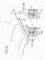
- the Figure 15A shows a body component K in the form of a car roof cladding with a circumferential folded board.
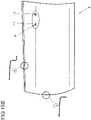
- the Figure 15B shows a body component K in the form of a door outer panel for a motor vehicle door with a recessed grip M in holes L1 and L2 formed therein for the attachment of a door handle.
- Details A and B in the Figure 15B show in section the design of the different edges of the outer door panel including the flanges.
- the conventional sequence of operations in the manufacture of such sheet metal components Figures 15A and 15B consists of drawing, cutting and bending in typically four tools and, if necessary, additionally - in the case of the outer door panel - of embossing and punching. All trimmed edge areas are more or less perpendicular to the working direction of the press device to be used.
- the folded areas are free of undercuts.
- FIG. 5 and 6A to 6G proposes drawing, complete trimming and all-round folding in a further developed (overall) composite tool W, ie the entire manufacturing process of the body component K takes place in the composite tool W.
- a possible further development aims at slightly different component geometries with flared flanges KF according to figure 8 away. It includes drawing, complete trimming, folding and post-forming in one tool.
- the reshaping refers to the setting of the flange angle in the closed tool, whereby a targeted compensation of the elastic angle deflection when opening the tool is achieved.
- Figures 10A and 10B proposes drawing, complete trimming, folding and embossing in a composite tool W, with flared flange areas KF having embossing P (cf. figure 9 ).
- the embossing operation can be used at the same time to adjust the flange angle (spring-back compensation).
- the figure 11 illustrates the production of multi-stepped rims using the compound tool W.
- the composite tool W shown and the method implemented with it provides for drawing, complete trimming, folding, embossing and punching, eg for the production of an outer door panel Figure 15B . Bending is done here on straight and flared flanges. Embossing takes place in the component face; can alternatively or additionally (also) take place in the area of the flange.
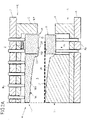
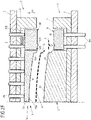
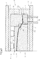
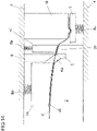
- the composite tool W comprises an upper structure O with a multi-part die 1 and a substructure U with a punch 2 and a sheet metal holder 3 that can be adjusted for this purpose Press and the substructure U are attached to a (press) table 6 of the press.
- the present two-part die 1 has an inner die 1A and an outer die 1B.
- the inner and outer dies 1A, 1B are relative moveable to each other.
- the outer matrix 1B encloses the inner matrix 1A at least in regions.
- the inner die 1A and the outer die 1B are adjustably mounted on an upper part 5 of the superstructure O via (upper air) bolts Bo. These bolts Bo protrude through passage openings 50 of the upper part 5 and thus aligned through openings 70 of a ram 7 of the press which is arranged above the upper part 5 and on which the upper part 5 is fixed. At least one spacer Z is provided on the upper part 5 in the area of the outer matrix 1B. Via this spacer Z, the upper part 5 can act on the outer die 1B during a press stroke along an adjustment direction Vu and cause an adjustment movement of the inner and outer dies 1A, 1B relative to one another.
- the inner die 1A is opposite the stamp 2 of the substructure U, which is immovably fixed to a lower part 4 of the substructure U.
- the lower part 4 in turn rests on the table 6 of the press.
- the stamp 2 forms a stamping surface 20 .
- This punch face 20 faces a die face 10A of the inner die 1A.
- the inner matrix 1A Adjacent to the outer matrix 1B, the inner matrix 1A forms a bending web 11A at the edge. This bending web 11A protrudes in the direction of the punch 2 and corresponds to a peripheral recess 21 on the punch 2.
- a bent edge portion Ka is formed on the body component K.
- This edge section Ka is formed at a separating edge at which a waste piece A is separated from the blank K' by shear cutting.
- the outer die 1B forms a cutting edge 11B and interacts with a sheet metal holder 3 of the substructure U.
- the sheet metal holder 3 is mounted on the substructure U in a translationally adjustable manner and forms a sheet metal holder surface 30 on which the waste piece A of the blank K′ to be separated is placed.
- the punch surface 20, together with the die surface 10A of the inner die 1A, the blank holder surface 30 and an opposite die surface 10B of the outer die 1B, defines a gap R between the punch 2, blank holder 3 and the two-part die 1. In this gap R is the Insert blank K ', and then in one Press stroke to shape and trim the body component K.
- the waste piece A is pressed in between the blank holder surface 30 and the opposite die surface 10B of the outer die 1B and held securely.
- the sheet metal holder 3 and the outer die 1B form a form-fitting area in the form of a groove-like depression 32 and a projection 12B.
- the composite tool W is open, ie, the space R is accessible and the sheet metal holder 3 is adjusted to a raised insertion position in the direction of the outer die 1B.
- the adjustment of the sheet metal holder 3 along an adjustment direction Vo is controlled via (under-air) bolts Bu. If the blank holder 3 is in its insertion or starting position, the blank holder surface 30 is approximately at the level of the highest point of the stamping surface 20.
- the inner die 1A and the outer die 1B, controlled via the (over-air) bolts Bo, are retracted this far that blank K' can be inserted and comes to rest on the blank holder surface 30 ( Figure 2A ).
- the force of the upper air cushion (ram cushion) defined by the bolts Bo is greater than the force of the lower air cushion (table drawing cushion) defined by the bolts Bu.
- the outer matrix 1B displaces the lower air cushion as the stroke progresses, ie as the upper structure O approaches the lower structure U further along the adjustment direction Vu.
- the pulling process begins.
- the surfaces 110A and 10B of the inner and outer matrices 1A, 1B remain at the same level, since they are each supported against the common upper air cushion via the row of bolts Bo ( Figure 2C ).
- the body component K is shaped and the drawing process is completed.
- the upper air bolts Bo are pushed into the (press) ram 7 via the inner die 1A.
- the upper air bolts Bo return empty behind the outer die 1B.
- the inner die 1A, the outer die 1B and the blank holder 3 come to a brief standstill until the outer die 1B is seated on the at least one spacer Z ( Figure 2D ).
- the inner die 1A continues to stand still, while the inner die 1A continues to displace the upper air bolts Bo acting on it.
- the outer die 1B is supported via the at least one spacer Z against the upper part 5 and the press ram 7 .
- the outer die 1B moves further downwards in the adjustment direction Vu, relative to the inner die 1A, with the sheet metal holder 7 being displaced.
- the inner die 1A fixes the body component K on the punch 2 and thereby assumes the function of a blank holder.
- the stamp 2 now has the function of a cutting attachment.
- the cutting edge 11B of the outer die 1B performs the function of a cutting blade.
- the cutting edge 11B shears into the sheet material until it breaks through.
- a cutting gap s is determined by a horizontal offset between punch 2 and outer die 1B ( Figure 1A ). This completes the cutting process.
- a drawing edge defined by the waste piece A is severed from the body component K ( Figure 2E ).
- the upper structure O moves with the press ram 7 and the upper part 5 upwards (in the adjustment direction Vo) and takes the inner and outer die 1A, 1B with it. It does not matter whether the upper air is pressurized or depressurized in this phase. Now the body component K and the waste piece A can be removed. This can be done simultaneously or sequentially, manually or mechanized, for example by robot suction spiders. Beneficial for the withdrawal is that the piece of waste that has been cut off comes to rest at a level below the separating edge of the body component (cf. Figure 2E ).
- the lower air with the sheet metal holder 3 only moves up again after the body component K and the waste piece A have been removed, in order to prevent the scrap from colliding with the body component K.
- the loading position starting position
- a new blank K' in the form of a single flat blank can be loaded.
- FIG. 1 , 1A and 2A to 2F and the Figures 3 and 4A to 4E show the component production with tightened board.
- the tightening of the board is necessary to position the drawn and trimmed body part K when Insertion in the subsequent bending tool to ensure.
- edge throwing there may be a risk of what is known as edge throwing.
- the raised edges represent a surface defect of the component along the fold line, which is particularly visible on the painted vehicle and therefore cannot be tolerated.
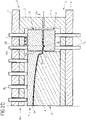
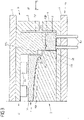
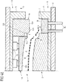
- the process sequence for the production of the body component K is divided here into seven phases, shown on a tool assembly with a counterholder 8 and hold-down device 1C according to FIG Figures 6A to 6G .
- the counter-holder 8 is supported on the lower part 4 via a spring element in the form of a gas pressure spring Gu and is pretensioned in the direction of the upper part 5 .
- the counter-holder 8 is opposite the cutting edge 9 of the upper structure O and is arranged between the punch 2 and a punch attachment 2B.
- the punch attachment 2B is arranged between the sheet metal holder 3 and an insertion area E for the cutting edge 9 of the first structure O.
- the hold-down device 1C is in turn arranged opposite the punch attachment 2B and is located between the cutting edge 9 and the outer die 1B.
- the composite tool W is open.
- the inner die 1A and the hold-down device 1C are supported on the extended bolt Bo of the ram cushion.
- the counter-holder 8 and the blank holder 3 are each in a raised insertion or starting position.
- the blank K' is inserted ( Figure 6A ).
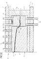
- the plunger 7 with the upper part 5 moves down.
- the outer die 1B sits on the blank holder 3.
- the beads on waste piece A are shaped and the edge of blank K' is clamped between blank holder 3 and outer die 1B ( Figure 6B ).
- the under-air can be switched to zero pressure.
- the free lowering of the sheet metal holder 3 releases the bead.
- the body component K can spring back elastically by a certain amount.
- the body component K is trimmed under less tension, which may have a positive effect on its quality and dimensional accuracy.
- the inner die 1A and the hold-down device 1C displace the ram cushion.
- the cutting edge 9 of the cutting knife engages with the blank K' and performs the trimming.
- the punch attachment 2B and cutting edge 9 can be provided with clearance angles for cutting.
- the board is first bent freely at a certain angle until the counter-holder 8 begins to take effect. From here the cutting knife with the cutting edge 9 acts as a folding strip.
- the cutting blade is preferably provided with a radius (not shown) on its edge facing the die 2 .
- the sheet metal holder 3 is continuously pushed further against the table cushion ( Figure 6D ).
- the superstructure O then moves to its starting position along the opposite adjustment direction Vo.
- the cutting knife with the cutting edge 9 is pulled back one after the other.
- the inner die 1A and the blank holder 1C release the body component K.
- the body component K and the waste piece A can be removed.
- the sheet metal holder 3 initially remains in its lower position, ie, in the design shown, the lower air moves up only with a delay.
- the waste piece A can be gripped from its stable position on the sheet metal holder 3 and the stamp attachment 2B.
- the counter-holder 8 should also only be raised with a delay in order to prevent deformation of the shelf. In the construction shown, this is realized with a controlled gas pressure spring Gu ( Figure 6G ).
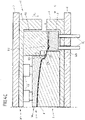
- the punch 2 has a defined undercut angle ⁇ in the area of the bent section Ka of the body component K (which forms the bent edge).
- a side wall 22 of the punch 2 thus jumps back by the undercut angle ⁇ in relation to the inner die 1A.
- additional complementary surfaces on the cutting edge 9 and/or the inner die 1A and precise incorporation of the pressure conditions in the composite tool W a targeted overbending of the rim in the closed tool can be achieved. After the elastic springing up when the composite tool W is opened, the rim then assumes the required angular position.
- the holder surface 80 of the counter holder 8 which is inclined at an angle ⁇ relative to the horizontal is also illustrated.
- the inclined holding surface 80 supports the controlled removal of the body part K between the counter-holder 8 and the cutting edge 9.
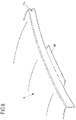
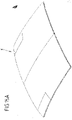
- a further exemplary embodiment relates to the production of sheet metal components with a tongue-shaped flange KF which adjoins the folded rim at least in regions and which, for example, fulfills the function of a joining flange and extends predominantly perpendicularly to the working direction of the press.
- a corresponding body part K is an example in the figure 8 shown.
- a composite tool W is used according to the variant figures 5 and 6A to 6G used, in which case a counter-holder 8 is absolutely necessary. Since the designed rim length is greater overall in the areas of the additional flange KF, the trimming takes place further out.
- the cutting blade with the cutting edge 9 and the counter-holder 8 are made wider by the corresponding amount.
- the counter-holder 8 preferably rests on at least one rigid spacer, which limits the stroke of the counter-holder downwards (in the direction of adjustment Vu).
- the stroke is already over when there is still a sheet metal dimension between the cutting edge 9 and the counterholder 8 that corresponds to the width of the flange KF.
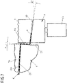
- the cutting edge 9 and the counterholder 8 can have a positive or negative angle ⁇ to the horizontal (see also figure 7 ).
- This angle ⁇ serves to form flanges KF which have a corresponding position in the compound tool W.
- the angle ⁇ is preferably dimensioned in such a way that it compensates for the elastic deflection of the flange when the composite tool W is opened by means of targeted overbending.
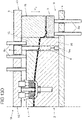
- FIG. 9 Joint flanges on a sheet metal component often have additional gradations or embossing P or the like, as in figure 9 is shown as an example.
- embossments P an embossing operation is required. This can be realized with a design variant of the composite tool W, as shown in FIG Figures 10A and 10B is shown.
- the cutting blade with the cutting edge 9 and its cutting strip also assumes the function of a folding strip and, lastly, a shaped strip for embossing.
- a pulling and trimming takes place according to the variant of the figures 5 and 6A to 6G .
- the hold-down device 1C of the upper structure O is again optional.
- the flow of material is preferably controlled by a counterholder 8 in order to ensure error-free shaping.
- the composite tool W and the manufacturing process to be implemented with it are coordinated in such a way that the trimmed or separating edge of the sheet metal leaves the counter-holder 8 shortly before the bottom dead center is reached.
- the stamp outline thus largely corresponds to the contour of the finished body part K.
- the stamp 2 and the cutting edge 9 have mutually opposite and mutually complementary shaped surfaces which correspond to the geometry of the issued board on the body part K.
- the forming surface 210 of the recess 21 opposite a first cutting edge section 90a has 2 steps for producing the embossing P on the punch.
- the holder surface 80 of the counter holder 8 and the complementary surface of a second cutting edge section 90b opposite this holder surface 80, which runs at an obtuse angle to the surface of the first cutting edge section 90a are largely flat ( Figure 10B ).
- the area between the cutting edge 9 and the punch 2 is again advantageously inclined by the angle ⁇ (cf. 7 ) in relation to the horizontal in order to form appropriate layers of the exhibited shelf or to bring in targeted overbends.
- FIG. 11 As in the sectional view of figure 11 is shown, the production of multi-stepped rims with a compound tool W is also possible.
- adjacent cutting edge sections 90a, 90b of the cutting edge 9 are stepped for this purpose, so that one cutting edge section 90b projects in the adjustment direction Vu in relation to the other cutting edge section 90a.
- the counter-holder 8 opposite the blade 9 accordingly has a holder surface 80 that is complementary to the blade sections 90a, 90b, so that a between the cutting edge 9 and the counter-holder 8 at the end of the press stroke formed board is stepped several times.
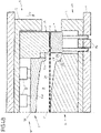
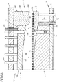
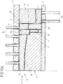
- One with the figures 12 and 13A to 13G shown variant of a composite tool W is based on the variant of the figures 5 and 6A to 6G and provides for the formation of a trough-shaped embossing in the component surface by means of an (embossing) insert 16 on the upper structure O during the cutting and folding in the edge area.
- the insert 16 is mounted on the upper part 5 so that it can be adjusted elastically relative to the inner matrix 1A.
- the elastic mounting is implemented via a number of spring elements F1, F2, via which the insert 16 is supported on the upper part 5.
- the production of the embossing on the body part - here, for example, in the form of a recessed grip M corresponding to the Figure 15B - is also realized in the press stroke and accomplished without additional adjustment drives.
- an embossing depression 201 of the stamp 2 formed in the stamp surface 20 is opposite the insert 16 .
- the insert 16 can dip into this embossing depression 201 when the inner die 1A and the punch 2 are
- a punch 17 rigidly fixed to the upper part 5 is guided on the insert 16 .
- the insert 16 is displaced against the spring elements F1, F2 in the upper part 5 with further adjustment of the upper part 5 in adjustment Vu and thus in a further, second adjustment phase.
- the punch 17 engages and punches the body component K as the adjustment continues, with the insert 16 taking on the function of a hold-down device.
- Perforation waste LA resulting from the perforation is disposed of via an opening in the embossing trough 201 , into which the punch 17 dips and which opens into a scrap channel 2010 .
- embossings in the type of recessed grip M in a drawing stage by means of a correspondingly contoured die and a correspondingly contoured punch. Unrest, waviness, raised edges, flat or sinking points on or around the recessed grip M, which represent intolerable surface defects on the body part, are often the result. Therefore, such embossings are often formed in subsequent operations with different hold-down and mold inserts.
- the proposed variant of the figures 12 and 13A to 13G facilitates the achievement of a component surface of high quality, since during the Shaping of the recessed grip M through the insert 16 of the sheet metal blank K' is still under biaxial tensile stress from the drawing and is held between the punch 2 and the inner die 1A. This tensile stress is superimposed on the states of stress that arise as a result of the embossing process in and around the recessed grip M and reduces the influence of the different processing lengths over the recessed grip M.
- holes can also be introduced independently of an embossing function, in that the punch 17 is guided in the inner die 1A.
- the inner die 1A then assumes the function of a hold-down device in the second adjustment phase for the perforation.
- embossing and/or punching that deviates from the working direction of the press is also possible if appropriate drives are used for the embossing and/or cutting elements be provided.
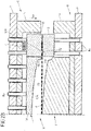
- the figure 14 also schematically illustrates a development of a composite tool W of figure 5 with punch attachment 2B integrated in punch 2.
- the punch attachment 2B is only separated from the punch surface 20 of the punch 2, which interacts with the inner die 1A, via the insertion area E for the cutting edge 9.
- the punch attachment 2B interacting with the separate hold-down device 1C of the upper part 5 is not spatially separated from the punch 2 as in the previously explained variants, but is part of the punch 2.
- An integration of the punch attachment 2B in the punch 2 is of course also included the previously explained variants possible.
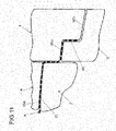
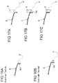
- the cutting edge 900 of the cutting strip thus has first cutting edge sections 900A, second cutting edge sections 900B and transition regions 901 located in between.
- first cutting edge sections 900A are each on the inside and the second cutting edge section 900B is on the outside, so that the first cutting edge sections 900A form an inner contour of the cutting edge 900 and the second cutting edge section 900B an outer contour of the Cutting edge 900 are defined. 1.
- the second cutting edge section 900B of the cutting edge 900 which defines the outer contour, thus protrudes here in relation to the first cutting edge section 900A, which defines the inner contour, so that when the die 1 and the punch 2 are pressed against one another, the cutting edge 9 first cuts its cutting edge 900 by means of the second cutting edge section 900B a second (subsequently bevelled) edge region II, before the cutting edge 9 carries out a trimming in the first edge regions I by means of the first cutting edge section 900A of its cutting edge 900.
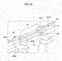
- a counter-holder 8 which is at least partially complementary to the cutting edge 9, is provided in the (tool) lower part 4, which in the plan view of FIG figure 20 is shown.
- This counterholder 8 is in its upper position during the trimming of the second edge areas II and the transitional edge areas III and acts as a counterknife in the transitional edge area III.
- uncontrolled tearing in the transitional edge region III is limited to a minimum length or even completely prevented.
- the cutting edge 9 sits in the first edge area I on the counterholder 8 and begins to displace it downwards (in the adjustment direction Vu) against a defined force as the press stroke progresses.
- the possibility of using a separate counterholder 8 in the area of the fold is unaffected if this is opportune for the component and/or the process.
- the counter-holder 8 for cutting and the counter-holder 8 for folding can also be made in one piece with a corresponding structural design and/or be supported against the same pressure elements in the lower part 4 .
- a counter-holder 8 is used from the outset for folding in the second edge area II, its contour in the transitional edge area III can also be designed as a bottom cutter. In this case, the trimming is carried out in advance in the first edge area I and then peels over the transition edge area III. Finally, the second edge area II is then cut and folded.
- the described function and tool design do not necessarily imply full-edged cutting in the first and second edge regions I and II.
- Crossing or peeling cutting can also be provided here as required.
- a cutting insert is provided on the upper or lower blade in the transition area 901 . Its cutting edge then protrudes by a distance of 0.5 mm to 3.0 mm compared to those of the cutting bar(s) in edge areas I and II. The cutting insert cuts into the transition edge region III and is then displaced so far that its cutting edge is at the same level as that of the first and second edge regions I and II. Then, the cutting edge portions 900A, 900B are engaged in the first and second edge portions I and II.
Claims (15)
- Outil composite pour la fabrication d'un composant plat en tôle (K), avec une première structure (O) présentant une matrice d'étirage (1) et une deuxième structure (U) présentant un poinçon d'étirage (2), dans lequel au moins la première structure (O) ou la deuxième structure (U) est au moins partiellement réglable en translation et au moins un support de tôle (3) réglable en translation par rapport au poinçon d'étirage (2) est prévu sur la deuxième structure (U) en plus du poinçon d'étirage (2), afin de presser la matrice d'étirage (1) et le poinçon d'étirage (2) l'un contre l'autre et de former par étirage le composant en tôle (K) à partir d'une ébauche de tôle (K') disposé entre la matrice d'étirage (1) et le poinçon d'étirage (2) et réalisée sous forme de platine individuelle, le support de tôle (3) étant adapté pour maintenir un bord extérieur de l'ébauche de tôle (K') à étirer sur le support de tôle (3),
dans lequel- la matrice d'étirage (1) de la première structure (O) est réalisée au moins en deux parties, avec une matrice intérieure (1A) et une matrice extérieure (1B), la matrice intérieure (1A) et la matrice extérieure (1B) étant réglables l'une par rapport à l'autre sur la première structure (O), et- la matrice extérieure (1B) et le support de tôle (3) réglable en translation par rapport au poinçon d'étirage (2) se font face et sont adaptés, lors du pressage de la matrice d'étirage (1) en deux parties et du poinçon d'étirage (2) l'un contre l'autre, de maintenir entre eux une pièce de rebut (A) de l'ébauche de tôle (K), qui est découpée au niveau du bord extérieur de l'ébauche de tôle (K') étirée lors du pressage de la matrice d'étirage (1) et du poinçon d'étirage (2) l'un contre l'autre,caractérisé en ce que
pour découper la pièce de rebut (A), une lame (9) est prévue sur la première structure (O), et un complément de poinçon (2B) est prévu en outre sur la deuxième structure (U), qui est agencé entre le support de tôle (3) et une zone d'introduction (E) pour la lame (9) de la première structure (O). - Outil composite selon la revendication 1, caractérisé en ce que la première structure (O) et la deuxième structure (U) sont adaptées pour former, avec le pressage de la matrice d'étirage (1) et du poinçon d'étirage (2) l'un contre l'autre, également une partie de bord (Ka) du composé en tôle (K), sur laquelle se trouve une arête de séparation résultant de la séparation de la pièce de rebut (A), après la séparation de la pièce de rebut (A), la première structure (O) et la deuxième structure (U) étant adaptées pour replier, avec le pressage de la matrice d'étirage (1) et du poinçon d'étirage (2) l'un contre l'autre, la partie de bord (Ka) du composé en tôle (K), sur laquelle se trouve l'arête de séparation, après la séparation de la pièce de rebut (A).
- Outil composite selon la revendication 1 ou 2, caractérisé en ce que(a) la matrice extérieure (1B) de la première structure (O) entoure au moins partiellement la matrice intérieure (1A) et/ou(b) la matrice intérieure (1A) est réglable sur la première structure (O) par rapport à la matrice extérieure (1B) ou la matrice extérieure (1B) est réglable sur la première structure (O) par rapport à la matrice intérieure (1A).
- Outil composite selon l'une quelconque des revendications précédentes, caractérisé en ce que le support de tôle (3) est réglable en translation pour l'étirage et le rognage des bords de l'ébauche de tôle (K') lors du pressage de la matrice d'étirage en deux parties (1) et du poinçon d'étirage (2) l'un contre l'autre.
- Outil composite selon la revendication 4, caractérisé en ce que le support de tôle (3)- est réglable sur la deuxième structure (U) par rapport au poinçon d'étirage (2) dans une position d'insertion sur la matrice extérieure (1B), dans laquelle l'ébauche de tôle (K') doit être agencée avec une section côté bord sur le support de tôle (3), et- lors du pressage de la matrice d'étirage (1) et du poinçon d'étirage (2) l'un contre l'autre, est réglable par rapport au poinçon d'étirage (2) dans une position de retenue différente de la position d'insertion, dans laquelle la pièce de rebut (A) découpée de l'ébauche de tôle (K') est maintenue entre la matrice extérieure (1B) et le support de tôle (3).
- Outil composite selon l'une quelconque des revendications précédentes, caractérisé en ce que(a) par le réglage en translation de la première structure (O) et de la deuxième structure (U) l'une vers l'autre, le support de tôle (3) est réglable par rapport au poinçon (2) et/ou les matrices intérieure et extérieure (1A, 1B) sont réglables l'une par rapport à l'autre, et/ou(b) sur la première structure (O) il est prévu en outre un serre-flan (1C), qui est agencé entre la matrice intérieure (1A) et la matrice extérieure (1B), et/ou(c) la première structure (O) et la deuxième structure (U) sont adaptées pour découper, avec le pressage de la matrice d'étirage (1) et du poinçon d'étirage (2) l'un contre l'autre, la pièce de rebut (A) par cisaillage au moyen d'un mouvement relatif entre les matrices extérieure et intérieure (1A, 1B).
- Outil composite selon l'une quelconque des revendications précédentes, caractérisé en ce que(a) la lame (9) est montée sur la matrice extérieure (1B), ou(b) la matrice intérieure (1A) de la matrice d'étirage (1) en au moins deux parties est montée sur la première structure (O) de manière à être réglable par rapport à la lame (9).
- Outil composite selon la revendication 7, caractérisé en ce que, lorsque la lame (9) est prévu sur la première structure (O), par rapport à laquelle la matrice intérieure (1A) de la matrice d'étirage (1) en au moins deux parties est montée de manière réglable sur la première structure (O), la lame (9) est réalisé avec une barre de coupe, qui (a) lors du pressage de la matrice d'étirage (1) et du poinçon d'étirage (2) l'un contre l'autre, agit en même temps comme barre de pliage ou qui (b) lors du pressage de la matrice d'étirage (1) et du poinçon d'étirage (2) l'un contre l'autre, coopère avec un contre-support (8) et agit comme barre de pliage contre ce contre-support (8).
- Outil composite selon la revendication 8, caractérisé en ce qu'une arête de coupe (900) de la barre de coupe présente au moins une première section d'arête de coupe (900A) et au moins une deuxième section d'arête de coupe (900B), dans lequel, par rapport à une direction orientée de la matrice intérieure (1A) vers la matrice extérieure (1B), la au moins une première section d'arête de coupe (900A) se trouve à l'intérieur et la au moins une deuxième section d'arête de coupe (900B) se trouve à l'extérieur, de sorte qu'avec ladite au moins une première section d'arête de coupe (900A) un contour intérieur de l'arête de coupe (900) est défini, et avec ladite au moins une deuxième section d'arête de coupe (900B) un contour extérieur de l'arête de coupe (900) est défini.
- Outil composite selon la revendication 9, caractérisé en ce que(a) ladite au moins une deuxième section d'arête de coupe (900B) définissant le contour extérieur de l'arête de coupe (900) fait saillie par rapport à la au moins une première section d'arête de coupe (900A) définissant le contour intérieur, et/ou(b) le contre-support (8) coopérant avec la barre de coupe est conçu et prévu pour agir, pour une zone de transition (901) de l'arête de coupe (900), dans laquelle l'arête de coupe (900) passe de ladite au moins une première section d'arête de coupe (900A) à ladite au moins une deuxième section d'arête de coupe (900B), comme contre-couteau lors du pressage de la matrice d'étirage (1) et du poinçon d'étirage (2) l'un contre l'autre, et/ou(c) le contre-support (8) coopérant avec la barre de coupe est conçu et prévu pour être déplacé, lors du pressage de la matrice d'étirage (1) et du poinçon d'étirage (2) l'un contre l'autre, par la lame (9) s'appliquant contre le contre-support (8) par ladite au moins une première section d'arête de coupe (900A), après qu'un rognage de l'ébauche de tôle (K') a été effectué au moyen de ladite au moins une deuxième section d'arête de coupe (900B).
- Outil composite selon l'une quelconque des revendications précédentes, caractérisé en ce que la première structure (O) et la deuxième structure (U) sont adaptées pour réaliser au moins un bossage (M, P) sur le composant en tôle (K), avec le pressage de la matrice d'étirage (1) et du poinçon d'étirage (2) l'un contre l'autre, sur une section de bord (Ka) du composant en tôle (K), sur laquelle est présente une arête de séparation résultant de la séparation de la pièce de rebut (A).
- Outil composite selon les revendications 7 et 11, caractérisé en ce que, lorsque la lame (9) est prévu sur la première structure (O), par rapport à laquelle la matrice intérieure (1A) de la matrice d'étirage (1) en au moins deux parties est montée de manière réglable sur la première structure (O), la lame (9) est formé avec une barre de coupe qui, lors du pressage de la matrice (1) et du poinçon d'étirage (2) l'un contre l'autre, en même temps agit comme barre de pliage et comme barre de formage pour prévoir le bossage (P), afin de prévoir le bossage (P) sur une jante biseautée de la section de bord (Ka).
- Outil composite selon l'une quelconque des revendications précédentes, caractérisé en ce que sur la première structure (O) un insert (16) est prévu, au moyen duquel un bossage (M) est réalisé lors de l'étirage ou après la fin de l'étirage, et/ou sur la première structure (O) un poinçon (17) est prévu en outre pour réaliser au moins un trou (L1, L2) sur le composant en tôle (K).
- Outil composite selon la revendication 13, caractérisé en ce que le poinçon (17) est prévu pour réaliser le au moins un trou (L1, L2) sur le bossage (M) réalisé au moyen de l'insert (16) et l'insert (16) est monté de manière réglable sur la première structure (O), de sorte que l'insert (16), après la réalisation du bossage (M) dans une première phase de réglage, est déplacé lors de la poursuite du pressage de la matrice d'étirage (1) et du poinçon d'étirage (2) l'un contre l'autre dans une deuxième phase de réglage suivante et le poinçon (17) réalise le au moins un trou (L1, L2).
- Procédé de fabrication d'un composant plat en tôle (K) au moyen d'un dispositif d'étirage qui comprend une première structure (O) présentant une matrice d'étirage (1) et une deuxième structure (U) présentant un poinçon d'étirage (2), dans lequel au moins la première structure (O) ou la deuxième structure (U) est réglée au moins partiellement en translation, et au moins un support de tôle (3) réglable en translation par rapport au poinçon d'étirage (2) est prévu sur la deuxième structure (U) en plus du poinçon d'étirage (2), afin de presser la matrice d'étirage (1) et le poinçon d'étirage (2) l'un contre l'autre et de former par étirage le composant en tôle (K) à partir d'une ébauche de tôle (K') disposée entre la matrice d'étirage (1) et le poinçon d'étirage (2) et réalisée sous forme de platine individuelle, un bord extérieur de l'ébauche de tôle (K') à étirer étant retenu sur le support de tôle (3),
dans lequel- la matrice d'étirage (1) de la première structure (O) est réalisée au moins en deux parties, avec une matrice intérieure (1A) et une matrice extérieure (1 B), la matrice intérieure (1A) et la matrice extérieure (1B) étant réglables l'une par rapport à l'autre sur la première structure (O), et- la matrice extérieure (1B) et le support de tôle (3) réglable en translation par rapport au poinçon d'étirage (2) sont opposés l'un à l'autre et la matrice extérieure (1B) et le support de tôle (3) maintiennent entre eux une pièce de rebut (A) de l'ébauche de tôle (K) lors du pressage de la matrice d'étirage en deux parties (1) et du poinçon d'étirage (2) l'un contre l'autre, qui est découpée au niveau du bord extérieur de l'ébauche de tôle étirée (K') lors du pressage de la matrice d'étirage (1) et du poinçon d'étirage (2) l'un contre l'autre,caractérisé en ce que
pour découper la pièce de rebut (A), une lame (9) est prévue sur la première structure (O), et sur la deuxième structure (U) un complément de poinçon (2B) est prévu en outre, qui est agencé entre le support de tôle (3) et une zone d'introduction (E) pour la lame (9) de la première structure (O).
Priority Applications (2)
| Application Number | Priority Date | Filing Date | Title |
|---|---|---|---|
| RS20220849A RS63631B1 (sr) | 2017-05-10 | 2018-05-09 | Kombinovani alat i postupak za proizvodnju komponente od lima |
| HRP20221138TT HRP20221138T1 (hr) | 2017-05-10 | 2018-05-09 | Sastavljeni alat i postupak proizvodnje limene komponente |
Applications Claiming Priority (2)
| Application Number | Priority Date | Filing Date | Title |
|---|---|---|---|
| DE102017207934.7A DE102017207934A1 (de) | 2017-05-10 | 2017-05-10 | Verbundwerkzeug und Verfahren zur Herstellung eines Blechbauteils |
| DE202017107906.6U DE202017107906U1 (de) | 2017-05-10 | 2017-12-22 | Verbundwerkzeug zur Herstellung eines Blechbauteils |
Publications (2)
| Publication Number | Publication Date |
|---|---|
| EP3401032A1 EP3401032A1 (fr) | 2018-11-14 |
| EP3401032B1 true EP3401032B1 (fr) | 2022-07-06 |
Family
ID=63372620
Family Applications (1)
| Application Number | Title | Priority Date | Filing Date |
|---|---|---|---|
| EP18171616.8A Active EP3401032B1 (fr) | 2017-05-10 | 2018-05-09 | Outil composite et procédé de fabrication d'un élément en tôle |
Country Status (10)
| Country | Link |
|---|---|
| EP (1) | EP3401032B1 (fr) |
| DE (2) | DE102017207934A1 (fr) |
| DK (1) | DK3401032T3 (fr) |
| ES (1) | ES2927084T3 (fr) |
| HR (1) | HRP20221138T1 (fr) |
| HU (1) | HUE059995T2 (fr) |
| LT (1) | LT3401032T (fr) |
| PL (1) | PL3401032T3 (fr) |
| PT (1) | PT3401032T (fr) |
| RS (1) | RS63631B1 (fr) |
Families Citing this family (4)
| Publication number | Priority date | Publication date | Assignee | Title |
|---|---|---|---|---|
| CN113345743B (zh) * | 2021-05-13 | 2023-06-30 | 南京越坤电气自动化有限公司 | 一种双向式灭弧罩固定片生产装置 |
| CN113500141B (zh) * | 2021-07-16 | 2023-06-23 | 深圳市鹏福创新科技有限公司 | 一种高透光轻薄盖板及其生产工艺 |
| WO2024015636A1 (fr) * | 2022-07-15 | 2024-01-18 | Magna International Inc. | Ensemble matrice pour la fabrication de portières de véhicule |
| CN115284005A (zh) * | 2022-08-17 | 2022-11-04 | 柴洪磊 | 一种三元锂电池外壳加工设备 |
Family Cites Families (9)
| Publication number | Priority date | Publication date | Assignee | Title |
|---|---|---|---|---|
| JPH09271856A (ja) * | 1996-04-08 | 1997-10-21 | Kanto Auto Works Ltd | プレス成形型 |
| DE10224711A1 (de) * | 2002-06-04 | 2004-01-08 | Daimlerchrysler Ag | Verfahren zum optimierenden Einstellen einer Umformgeometrie eines Umformwerkzeugs, entsprechendes Umformwerkzeug und geeignetes Versuchswerkzeug |
| US6843089B2 (en) * | 2002-10-23 | 2005-01-18 | General Motors Corporation | Method of producing surface features in sheet metal using superplastic forming |
| JP2004314147A (ja) * | 2003-04-18 | 2004-11-11 | Honda Motor Co Ltd | プレス成形用複合金型 |
| DE102006040224A1 (de) * | 2006-08-28 | 2008-03-20 | Magna Automotive Services Gmbh | Verfahren und Werkzeug zum Warmumformen eines Metallwerkstücks |
| DE102008034996B4 (de) * | 2008-07-25 | 2010-11-18 | Benteler Automobiltechnik Gmbh | Vorrichtung zum Warmformen, Presshärten und Schneiden eines Halbzeugs aus härtbarem Stahl |
| DE102008047971B3 (de) * | 2008-09-18 | 2010-05-12 | Aisin Takaoka Co., Ltd., Toyota | Verfahren und Vorrichtung zum Presshärten eines metallischen Formbauteils |
| DE102011110597A1 (de) * | 2010-08-18 | 2012-07-26 | Elisabeth Braun | Warmumformvorrichtung mit Schneideeinrichtung |
| CN113373288A (zh) * | 2013-10-21 | 2021-09-10 | 麦格纳国际公司 | 用于修剪热成型部件的方法 |
-
2017
- 2017-05-10 DE DE102017207934.7A patent/DE102017207934A1/de active Pending
- 2017-12-22 DE DE202017107906.6U patent/DE202017107906U1/de active Active
-
2018
- 2018-05-09 HR HRP20221138TT patent/HRP20221138T1/hr unknown
- 2018-05-09 PT PT181716168T patent/PT3401032T/pt unknown
- 2018-05-09 ES ES18171616T patent/ES2927084T3/es active Active
- 2018-05-09 DK DK18171616.8T patent/DK3401032T3/da active
- 2018-05-09 EP EP18171616.8A patent/EP3401032B1/fr active Active
- 2018-05-09 RS RS20220849A patent/RS63631B1/sr unknown
- 2018-05-09 PL PL18171616.8T patent/PL3401032T3/pl unknown
- 2018-05-09 HU HUE18171616A patent/HUE059995T2/hu unknown
- 2018-05-09 LT LTEP18171616.8T patent/LT3401032T/lt unknown
Also Published As
| Publication number | Publication date |
|---|---|
| HUE059995T2 (hu) | 2023-01-28 |
| PL3401032T3 (pl) | 2023-01-09 |
| RS63631B1 (sr) | 2022-10-31 |
| ES2927084T3 (es) | 2022-11-02 |
| HRP20221138T1 (hr) | 2022-12-09 |
| PT3401032T (pt) | 2022-09-20 |
| DK3401032T3 (da) | 2022-09-19 |
| DE102017207934A1 (de) | 2018-11-15 |
| EP3401032A1 (fr) | 2018-11-14 |
| DE202017107906U1 (de) | 2018-08-14 |
| LT3401032T (lt) | 2022-10-10 |
Similar Documents
| Publication | Publication Date | Title |
|---|---|---|
| EP3401032B1 (fr) | Outil composite et procédé de fabrication d'un élément en tôle | |
| DE102008037612B4 (de) | Verfahren und Werkzeugsatz zur Herstellung von flanschbehafteten, hoch maßhaltigen und tiefgezogenen Halbschalen | |
| EP2512702B1 (fr) | Procédé et dispositif de fabrication d'un élément en demi-coque | |
| EP2217393B1 (fr) | Procédé de production de demi-coques, à haute prescription des dimensions | |
| DE102007021798B4 (de) | Vorrichtung zur Herstellung von Profilen | |
| DE102018106520B3 (de) | Verfahren zur Bearbeitung eines Blechprofils | |
| EP2802425B1 (fr) | Dispositif et procede d'emboutissage d'elements en forme de coque avec decoupe du fond et de la paroi integree | |
| EP2208551B1 (fr) | Procédé de fabrication d'une pièce de tôle préformée complexe | |
| EP1781430B1 (fr) | Procede et dispositif pour produire un profile creux a soudure longitudinale | |
| DE19842750B4 (de) | Verfahren und Herstellung von tiefgezogenen Hohlteilen und Ziehwerkzeug | |
| DE102013019634A1 (de) | Herstellung eines Blechformteils mit lokalem elektromagnetischen Umformen des Blechmaterials zur Erzeugung einer Blechformteilkante | |
| EP2108467A2 (fr) | Procédé de fabrication de demi-coques de dimensions très précises | |
| EP1492635B1 (fr) | Procede et outil de matricage destines a la fabrication d'un composant a partir d'une tole de structure courbe | |
| EP2060336B1 (fr) | Outil de coupe et bordage de pièces usinées plates | |
| EP3565677A1 (fr) | Procédé de fabrication de pièces métalliques en feuille et dispositif associé | |
| WO2012062244A1 (fr) | Procédé et dispositif de façonnage d'une pièce | |
| DE102017102356B3 (de) | Verfahren und Vorrichtung zum Herstellen eines Kragens an einem Werkstück | |
| EP3691807A1 (fr) | Procédé et dispositif pour la fabrication d'éléments en tôle façonnés au moyen d'éléments préfaçonnés | |
| EP3253509B1 (fr) | Procédé et dispositif pour réaliser un rebord au niveau d'une pièce | |
| EP4321271A1 (fr) | Procédé de fabrication d'un composant de véhicule automobile par formage à chaud à découpe intégrée | |
| DE102010053842A1 (de) | Pressenvorrichtung und Verfahren zur Herstellung eines schalenförmigen Bauteils | |
| DE102014004165B4 (de) | Blechbauteil mit Prägekontur sowie Verfahren zur Herstellung eines solchen Blechbauteils | |
| DE102011051801B4 (de) | Verfahren und Vorrichtung zur Herstellung von Kernspangen und Kernspange | |
| WO2005046902A1 (fr) | Outil et deformation haute pression interne d'un profile creux | |
| WO2005046898A2 (fr) | Outil et procede de decoupe d'un profile creux |
Legal Events
| Date | Code | Title | Description |
|---|---|---|---|
| REG | Reference to a national code |
Ref country code: HR Ref legal event code: TUEP Ref document number: P20221138T Country of ref document: HR |
|
| PUAI | Public reference made under article 153(3) epc to a published international application that has entered the european phase |
Free format text: ORIGINAL CODE: 0009012 |
|
| STAA | Information on the status of an ep patent application or granted ep patent |
Free format text: STATUS: THE APPLICATION HAS BEEN PUBLISHED |
|
| AK | Designated contracting states |
Kind code of ref document: A1 Designated state(s): AL AT BE BG CH CY CZ DE DK EE ES FI FR GB GR HR HU IE IS IT LI LT LU LV MC MK MT NL NO PL PT RO RS SE SI SK SM TR |
|
| AX | Request for extension of the european patent |
Extension state: BA ME |
|
| STAA | Information on the status of an ep patent application or granted ep patent |
Free format text: STATUS: REQUEST FOR EXAMINATION WAS MADE |
|
| 17P | Request for examination filed |
Effective date: 20190510 |
|
| RBV | Designated contracting states (corrected) |
Designated state(s): AL AT BE BG CH CY CZ DE DK EE ES FI FR GB GR HR HU IE IS IT LI LT LU LV MC MK MT NL NO PL PT RO RS SE SI SK SM TR |
|
| STAA | Information on the status of an ep patent application or granted ep patent |
Free format text: STATUS: EXAMINATION IS IN PROGRESS |
|
| 17Q | First examination report despatched |
Effective date: 20210716 |
|
| STAA | Information on the status of an ep patent application or granted ep patent |
Free format text: STATUS: EXAMINATION IS IN PROGRESS |
|
| GRAP | Despatch of communication of intention to grant a patent |
Free format text: ORIGINAL CODE: EPIDOSNIGR1 |
|
| STAA | Information on the status of an ep patent application or granted ep patent |
Free format text: STATUS: GRANT OF PATENT IS INTENDED |
|
| INTG | Intention to grant announced |
Effective date: 20220125 |
|
| GRAS | Grant fee paid |
Free format text: ORIGINAL CODE: EPIDOSNIGR3 |
|
| GRAA | (expected) grant |
Free format text: ORIGINAL CODE: 0009210 |
|
| STAA | Information on the status of an ep patent application or granted ep patent |
Free format text: STATUS: THE PATENT HAS BEEN GRANTED |
|
| AK | Designated contracting states |
Kind code of ref document: B1 Designated state(s): AL AT BE BG CH CY CZ DE DK EE ES FI FR GB GR HR HU IE IS IT LI LT LU LV MC MK MT NL NO PL PT RO RS SE SI SK SM TR |
|
| REG | Reference to a national code |
Ref country code: AT Ref legal event code: REF Ref document number: 1502495 Country of ref document: AT Kind code of ref document: T Effective date: 20220715 Ref country code: CH Ref legal event code: EP |
|
| REG | Reference to a national code |
Ref country code: DE Ref legal event code: R096 Ref document number: 502018010070 Country of ref document: DE |
|
| REG | Reference to a national code |
Ref country code: IE Ref legal event code: FG4D Free format text: LANGUAGE OF EP DOCUMENT: GERMAN |
|
| REG | Reference to a national code |
Ref country code: RO Ref legal event code: EPE |
|
| REG | Reference to a national code |
Ref country code: FI Ref legal event code: FGE Ref country code: DK Ref legal event code: T3 Effective date: 20220914 |
|
| REG | Reference to a national code |
Ref country code: PT Ref legal event code: SC4A Ref document number: 3401032 Country of ref document: PT Date of ref document: 20220920 Kind code of ref document: T Free format text: AVAILABILITY OF NATIONAL TRANSLATION Effective date: 20220915 |
|
| REG | Reference to a national code |
Ref country code: NL Ref legal event code: FP |
|
| REG | Reference to a national code |
Ref country code: SE Ref legal event code: TRGR |
|
| REG | Reference to a national code |
Ref country code: ES Ref legal event code: FG2A Ref document number: 2927084 Country of ref document: ES Kind code of ref document: T3 Effective date: 20221102 |
|
| REG | Reference to a national code |
Ref country code: NO Ref legal event code: T2 Effective date: 20220706 |
|
| REG | Reference to a national code |
Ref country code: EE Ref legal event code: FG4A Ref document number: E022677 Country of ref document: EE Effective date: 20220920 |
|
| REG | Reference to a national code |
Ref country code: GR Ref legal event code: EP Ref document number: 20220401954 Country of ref document: GR Effective date: 20221109 |
|
| REG | Reference to a national code |
Ref country code: HR Ref legal event code: T1PR Ref document number: P20221138 Country of ref document: HR |
|
| REG | Reference to a national code |
Ref country code: SK Ref legal event code: T3 Ref document number: E 40731 Country of ref document: SK |
|
| REG | Reference to a national code |
Ref country code: HU Ref legal event code: AG4A Ref document number: E059995 Country of ref document: HU |
|
| PG25 | Lapsed in a contracting state [announced via postgrant information from national office to epo] |
Ref country code: IS Free format text: LAPSE BECAUSE OF FAILURE TO SUBMIT A TRANSLATION OF THE DESCRIPTION OR TO PAY THE FEE WITHIN THE PRESCRIBED TIME-LIMIT Effective date: 20221106 |
|
| REG | Reference to a national code |
Ref country code: DE Ref legal event code: R097 Ref document number: 502018010070 Country of ref document: DE |
|
| PG25 | Lapsed in a contracting state [announced via postgrant information from national office to epo] |
Ref country code: SM Free format text: LAPSE BECAUSE OF FAILURE TO SUBMIT A TRANSLATION OF THE DESCRIPTION OR TO PAY THE FEE WITHIN THE PRESCRIBED TIME-LIMIT Effective date: 20220706 |
|
| PLBE | No opposition filed within time limit |
Free format text: ORIGINAL CODE: 0009261 |
|
| STAA | Information on the status of an ep patent application or granted ep patent |
Free format text: STATUS: NO OPPOSITION FILED WITHIN TIME LIMIT |
|
| REG | Reference to a national code |
Ref country code: HR Ref legal event code: ODRP Ref document number: P20221138 Country of ref document: HR Payment date: 20230505 Year of fee payment: 6 |
|
| 26N | No opposition filed |
Effective date: 20230411 |
|
| PG25 | Lapsed in a contracting state [announced via postgrant information from national office to epo] |
Ref country code: AL Free format text: LAPSE BECAUSE OF FAILURE TO SUBMIT A TRANSLATION OF THE DESCRIPTION OR TO PAY THE FEE WITHIN THE PRESCRIBED TIME-LIMIT Effective date: 20220706 |
|
| PGFP | Annual fee paid to national office [announced via postgrant information from national office to epo] |
Ref country code: LU Payment date: 20230517 Year of fee payment: 6 |
|
| PGFP | Annual fee paid to national office [announced via postgrant information from national office to epo] |
Ref country code: RS Payment date: 20230509 Year of fee payment: 6 Ref country code: RO Payment date: 20230502 Year of fee payment: 6 Ref country code: PT Payment date: 20230428 Year of fee payment: 6 Ref country code: NO Payment date: 20230519 Year of fee payment: 6 Ref country code: NL Payment date: 20230519 Year of fee payment: 6 Ref country code: LT Payment date: 20230425 Year of fee payment: 6 Ref country code: IT Payment date: 20230531 Year of fee payment: 6 Ref country code: IE Payment date: 20230516 Year of fee payment: 6 Ref country code: FR Payment date: 20230517 Year of fee payment: 6 Ref country code: ES Payment date: 20230621 Year of fee payment: 6 Ref country code: EE Payment date: 20230518 Year of fee payment: 6 Ref country code: DK Payment date: 20230522 Year of fee payment: 6 Ref country code: DE Payment date: 20230414 Year of fee payment: 6 Ref country code: CZ Payment date: 20230426 Year of fee payment: 6 Ref country code: CY Payment date: 20230428 Year of fee payment: 6 Ref country code: CH Payment date: 20230602 Year of fee payment: 6 Ref country code: BG Payment date: 20230516 Year of fee payment: 6 |
|
| PGFP | Annual fee paid to national office [announced via postgrant information from national office to epo] |
Ref country code: TR Payment date: 20230503 Year of fee payment: 6 Ref country code: SK Payment date: 20230502 Year of fee payment: 6 Ref country code: SI Payment date: 20230503 Year of fee payment: 6 Ref country code: SE Payment date: 20230522 Year of fee payment: 6 Ref country code: PL Payment date: 20230418 Year of fee payment: 6 Ref country code: LV Payment date: 20230517 Year of fee payment: 6 Ref country code: HU Payment date: 20230504 Year of fee payment: 6 Ref country code: HR Payment date: 20230505 Year of fee payment: 6 Ref country code: GR Payment date: 20230516 Year of fee payment: 6 Ref country code: FI Payment date: 20230523 Year of fee payment: 6 Ref country code: AT Payment date: 20230516 Year of fee payment: 6 |
|
| PGFP | Annual fee paid to national office [announced via postgrant information from national office to epo] |
Ref country code: BE Payment date: 20230517 Year of fee payment: 6 |
|
| PGFP | Annual fee paid to national office [announced via postgrant information from national office to epo] |
Ref country code: MT Payment date: 20230522 Year of fee payment: 6 Ref country code: GB Payment date: 20230522 Year of fee payment: 6 |
|
| PGFP | Annual fee paid to national office [announced via postgrant information from national office to epo] |
Ref country code: AL Payment date: 20230414 Year of fee payment: 6 |
|
| PG25 | Lapsed in a contracting state [announced via postgrant information from national office to epo] |
Ref country code: MC Free format text: LAPSE BECAUSE OF FAILURE TO SUBMIT A TRANSLATION OF THE DESCRIPTION OR TO PAY THE FEE WITHIN THE PRESCRIBED TIME-LIMIT Effective date: 20220706 |
|
| PG25 | Lapsed in a contracting state [announced via postgrant information from national office to epo] |
Ref country code: MC Free format text: LAPSE BECAUSE OF FAILURE TO SUBMIT A TRANSLATION OF THE DESCRIPTION OR TO PAY THE FEE WITHIN THE PRESCRIBED TIME-LIMIT Effective date: 20220706 |
|
| PGFP | Annual fee paid to national office [announced via postgrant information from national office to epo] |
Ref country code: MK Payment date: 20230427 Year of fee payment: 6 |