EP3400803B2 - Verfahren und vorrichtung zum ausrichten von gewickelten teigprodukten entlang einer bremsstrecke - Google Patents
Verfahren und vorrichtung zum ausrichten von gewickelten teigprodukten entlang einer bremsstrecke Download PDFInfo
- Publication number
- EP3400803B2 EP3400803B2 EP18164109.3A EP18164109A EP3400803B2 EP 3400803 B2 EP3400803 B2 EP 3400803B2 EP 18164109 A EP18164109 A EP 18164109A EP 3400803 B2 EP3400803 B2 EP 3400803B2
- Authority
- EP
- European Patent Office
- Prior art keywords
- dough product
- dough
- section
- wound
- speed
- Prior art date
- Legal status (The legal status is an assumption and is not a legal conclusion. Google has not performed a legal analysis and makes no representation as to the accuracy of the status listed.)
- Active
Links
Images

Classifications
-
- A—HUMAN NECESSITIES
- A21—BAKING; EDIBLE DOUGHS
- A21C—MACHINES OR EQUIPMENT FOR MAKING OR PROCESSING DOUGHS; HANDLING BAKED ARTICLES MADE FROM DOUGH
- A21C9/00—Other apparatus for handling dough or dough pieces
- A21C9/08—Depositing, arranging and conveying apparatus for handling pieces, e.g. sheets of dough
- A21C9/088—Folding or bending discrete dough pieces or dough strips
-
- A—HUMAN NECESSITIES
- A21—BAKING; EDIBLE DOUGHS
- A21C—MACHINES OR EQUIPMENT FOR MAKING OR PROCESSING DOUGHS; HANDLING BAKED ARTICLES MADE FROM DOUGH
- A21C3/00—Machines or apparatus for shaping batches of dough before subdivision
- A21C3/06—Machines for coiling sheets of dough, e.g. for producing rolls
-
- A—HUMAN NECESSITIES
- A21—BAKING; EDIBLE DOUGHS
- A21C—MACHINES OR EQUIPMENT FOR MAKING OR PROCESSING DOUGHS; HANDLING BAKED ARTICLES MADE FROM DOUGH
- A21C9/00—Other apparatus for handling dough or dough pieces
- A21C9/08—Depositing, arranging and conveying apparatus for handling pieces, e.g. sheets of dough
- A21C9/085—Separating, spacing, orienting or aligning discrete dough pieces, e.g. after passing a cutting device
-
- A—HUMAN NECESSITIES
- A21—BAKING; EDIBLE DOUGHS
- A21D—TREATMENT OF FLOUR OR DOUGH FOR BAKING, e.g. BY ADDITION OF MATERIALS; BAKING; BAKERY PRODUCTS
- A21D8/00—Methods for preparing or baking dough
- A21D8/02—Methods for preparing dough; Treating dough prior to baking
-
- B—PERFORMING OPERATIONS; TRANSPORTING
- B65—CONVEYING; PACKING; STORING; HANDLING THIN OR FILAMENTARY MATERIAL
- B65G—TRANSPORT OR STORAGE DEVICES, e.g. CONVEYORS FOR LOADING OR TIPPING, SHOP CONVEYOR SYSTEMS OR PNEUMATIC TUBE CONVEYORS
- B65G15/00—Conveyors having endless load-conveying surfaces, i.e. belts and like continuous members, to which tractive effort is transmitted by means other than endless driving elements of similar configuration
- B65G15/10—Conveyors having endless load-conveying surfaces, i.e. belts and like continuous members, to which tractive effort is transmitted by means other than endless driving elements of similar configuration comprising two or more co-operating endless surfaces with parallel longitudinal axes, or a multiplicity of parallel elements, e.g. ropes defining an endless surface
- B65G15/12—Conveyors having endless load-conveying surfaces, i.e. belts and like continuous members, to which tractive effort is transmitted by means other than endless driving elements of similar configuration comprising two or more co-operating endless surfaces with parallel longitudinal axes, or a multiplicity of parallel elements, e.g. ropes defining an endless surface with two or more endless belts
- B65G15/14—Conveyors having endless load-conveying surfaces, i.e. belts and like continuous members, to which tractive effort is transmitted by means other than endless driving elements of similar configuration comprising two or more co-operating endless surfaces with parallel longitudinal axes, or a multiplicity of parallel elements, e.g. ropes defining an endless surface with two or more endless belts the load being conveyed between the belts
- B65G15/16—Conveyors having endless load-conveying surfaces, i.e. belts and like continuous members, to which tractive effort is transmitted by means other than endless driving elements of similar configuration comprising two or more co-operating endless surfaces with parallel longitudinal axes, or a multiplicity of parallel elements, e.g. ropes defining an endless surface with two or more endless belts the load being conveyed between the belts between an auxiliary belt and a main belt
-
- A—HUMAN NECESSITIES
- A21—BAKING; EDIBLE DOUGHS
- A21D—TREATMENT OF FLOUR OR DOUGH FOR BAKING, e.g. BY ADDITION OF MATERIALS; BAKING; BAKERY PRODUCTS
- A21D6/00—Other treatment of flour or dough before baking, e.g. cooling, irradiating or heating
-
- B—PERFORMING OPERATIONS; TRANSPORTING
- B65—CONVEYING; PACKING; STORING; HANDLING THIN OR FILAMENTARY MATERIAL
- B65G—TRANSPORT OR STORAGE DEVICES, e.g. CONVEYORS FOR LOADING OR TIPPING, SHOP CONVEYOR SYSTEMS OR PNEUMATIC TUBE CONVEYORS
- B65G15/00—Conveyors having endless load-conveying surfaces, i.e. belts and like continuous members, to which tractive effort is transmitted by means other than endless driving elements of similar configuration
- B65G15/60—Arrangements for supporting or guiding belts, e.g. by fluid jets
- B65G15/62—Guides for sliding belts
-
- B—PERFORMING OPERATIONS; TRANSPORTING
- B65—CONVEYING; PACKING; STORING; HANDLING THIN OR FILAMENTARY MATERIAL
- B65G—TRANSPORT OR STORAGE DEVICES, e.g. CONVEYORS FOR LOADING OR TIPPING, SHOP CONVEYOR SYSTEMS OR PNEUMATIC TUBE CONVEYORS
- B65G2201/00—Indexing codes relating to handling devices, e.g. conveyors, characterised by the type of product or load being conveyed or handled
- B65G2201/02—Articles
- B65G2201/0202—Agricultural and processed food products
Definitions
- the invention relates to a method for aligning wrapped dough products in a defined final position according to the preamble of claim 1.
- the invention also relates to a device for carrying out the method according to the invention.
- a device for rolling dough into an oblong shape e.g. for making baguettes, is known from US Pat NL 8204931 A known.
- the device is used to increase the length of a rolled dough roll, in particular from a rectangular piece of dough, by rolling it out to a desired length.
- the device comprises a transfer zone for transferring a dough roll from a first to a second conveyor belt, the conveyor belts being driven in opposite directions and the second conveyor belt forming a two-belt system with a third conveyor belt arranged above the second conveyor belt.
- the second conveyor belt is temporarily stopped when a dough roll arrives, so that a roll of dough can be transferred without any problems.
- the arrival and the height of a roll of dough in a transfer zone are registered by means of a control device in order to avoid damaging the roll of dough during the transfer, for example by reversing the drive direction of the second conveyor belt
- a generic method and a generic device for aligning wrapped dough products in a defined final position are known. This method is used in particular to align dough products, such as croissants, wrapped from trapezoidal pieces of dough in a defined final position before baking.
- the method is based on the basic idea that the wrapped dough products, after passing through the wrapping section, are decelerated from an initial translational speed to a changed intermediate translational speed. To do this, the wrapped dough products pass through a braking section.
- the alignment of the dough products in the defined final position by braking along the braking distance requires the setting of relatively precise boundary conditions with regard to the initial and final speed of the dough product in order to prevent the dough product from rolling over the end, for example when the drive torque generated by the braking torque increases is big. Conversely, the drive torque generated by the braking torque must not be too small either, since otherwise the rolling movement caused by braking is not sufficient to reach the defined final position.
- the problem here is that the boundary conditions for braking along the braking distance have so far not been freely selectable.
- the initial speed of the dough product when it leaves the wrapping line is very much dependent on the production speed desired in each case, since the dough products are transported through the wrapping line at ever higher speeds at higher cycle frequencies.
- the higher cycle frequencies mean that the rotational speed of the dough pieces is always higher when they leave the wrapping section. This strong rotation of the dough pieces when leaving the wrapping section also leads to a tumbling movement of the dough pieces, which often makes it impossible to brake the dough pieces in a defined manner immediately after leaving the wrapping section.
- the method according to the invention is based on the basic idea that an additional control section is provided between the end of the winding section and before the start of the braking section, through which the wrapped dough products pass.
- the control section it is provided that two circulatingly driven conveyor belts are brought into engagement on the dough product after the winding section and the translational conveying speed of the wrapped dough products and/or the rotational speed of the wrapped dough products are changed and set to a predetermined setpoint.
- this makes it possible to change and set the translational conveying speed of the wrapped dough products waiting at the end of the wrapping section or the rotational speed of the wrapped dough products, which depends very much on the respective production frequency during wrapping, in such a way that the values in the control section are then set Boundary conditions allow reaching the defined final position when braking the dough products in the braking section.
- the rotational speed of the wrapped dough products is of great importance for the correct braking of the dough products in the braking section and the resulting setting of the defined final position within a specific range. It is precisely this rotational speed of the wrapped dough products that is greatly increased by increasing the cycle frequency in the wrapping section, which, however, makes it considerably more difficult to brake the dough products correctly in the braking section in order to set the defined final position. Up until now, the wrapped dough products have left the wrapping device with uncontrollable wobbling movements at high cycle frequencies. It is therefore particularly advantageous if the rotational speed of the wrapped dough products is slowed down in the control section in order not to exceed the maximum possible initial speed for braking when setting the defined final position in the braking section.
- How much the rotational speed of the wrapped dough products is slowed down in the control section depends on the production quality during braking in the braking section. It is particularly advantageous if the rotational speed of the wrapped dough products in the control section is slowed down to a value of zero, i.e. the dough products no longer rotate of their own accord at the end of the control section.
- the rotational speed of the wrapped dough product in the control section can also be reversed in the opposite direction, so that this rotational movement in the opposite direction corresponds precisely to the rotational movement during braking in the braking section.
- the required braking torque can be significantly reduced.
- the manner in which the wrapped dough products are slowed down in the braking section is fundamentally arbitrary. This can be done particularly easily with the use of a control section provided according to the invention in that the dough products are transferred from a first circulatingly driven conveyor belt at a first conveying speed to a second circulatingly driven conveyor belt with a second conveying speed. Due to the corresponding difference between the first conveying speed and the second conveying speed, the wrapped dough products can be slowed down by this transfer and thereby set in the desired rolling motion.
- the device according to the invention for carrying out the method according to the invention when aligning wrapped dough products comprises, in a generic manner, a wrapping section and a braking section. In the wrapping section, the pieces of dough are wrapped into dough products.
- the wrapped dough products can be set in a rolling motion by appropriate braking in order to enable the defined final position in which the end of the dough product is in contact with the base.
- the device according to the invention is characterized by a conveyor device which forms a control section between the winding section and the braking section.
- the conveyor device is characterized in that the conveyor device is formed from two revolving conveyor belts and the translatory conveying speed of the wrapped dough products or the rotational speed of the wrapped dough products can be changed when passing through the control section between the winding section and the braking section.
- the first conveyor belt can engage in the wrapped dough products from below and the second conveyor belt can engage in the wrapped dough products from above in a particularly simple manner.
- the peripheral speed of the first conveyor belt relative to the peripheral speed of the second conveyor belt, the translational conveying speed of the dough product or the rotational speed of the wrapped dough product can be changed in the desired manner and, if necessary, set to a predetermined setpoint due to the simultaneous engagement of the two conveyor belts.
- peripheral speed of the first conveyor belt and/or the peripheral speed of the second conveyor belt can be adjusted independently of one another.
- the upper conveyor belt of the conveyor device consists of at least two conveyor belts arranged at a distance from one another consists, whereby the two conveyor belts each come to rest eccentrically on the wrapped piece of dough.
- the two spaced-apart conveyor belts achieve a centering movement of the wrapped dough products as they pass through the control section.
- the resulting difference in height on the right or left side to the respective conveyor belts causes the wrapped pieces of dough to move in the direction of the desired central position.
- a conveyor belt with a lower conveying speed is arranged behind the lower conveyor belt of the control section to form the braking section.
- the braking section is then formed by the wrapped dough products being transferred from the lower conveyor belt of the control section to the conveyor belt behind it with the lower conveying speed. Due to the difference between the conveying speeds when transferring from the lower conveyor belt of the control section to the conveyor belt arranged behind it, the dough products are slowed down and set in the desired rolling motion by the braking moment caused by this.
- the system 01 includes a wrapping section 03 in which the dough products 02 are produced by wrapping triangular or trapezoidal pieces of dough.
- the dough products 02 are transported on a conveyor belt 04 in the conveying direction, with the dough products 02 resting against a stationary wrapping plate 05 at their upper crossing point.
- this means that the dough products 02 are moved at their lower peak at a conveying speed that corresponds to the circulation speed v1 of the conveyor belt 04, whereas the upper peak of the dough products 02 has the speed zero.
- the difference in speed between the wrapping plate 05 and the conveyor belt 04 sets the dough products 02 in a rotating wrapping motion, so that the dough products 02 have a translational conveying speed v1res at the end of the wrapping section 03.
- the winding section 03 is followed by a control section 06, which is formed from a lower conveyor belt 07 and an upper conveyor belt 08.
- the conveyor belt 07 runs at a conveying speed v2, where v2 corresponds precisely to the translational conveying speed vires of the dough products 02 at the end of the winding section 03.
- the circulating speed of the conveyor belt 08 can be set variably, so that depending on the circulating speed v3 of the conveyor belt 08 relative to the circulating speed v2 of the conveyor belt 07, there is a corresponding rotation of the dough products 02.
- v3 is chosen to be slightly smaller than v2, the dough products 02 rotate counterclockwise, whereas if v3 is slightly larger than v2, the dough products 02 rotate clockwise.
- the translatory conveying speed of the dough products 02 can be set in the same way by selecting v2 or v3.
- the conveying device 09 formed by the conveyor belts 07 and 08, which forms the control section 06 makes it possible for the dough products 02 coming from the wrapping section 03 to be set precisely in terms of their translational conveying speed and their rotational speed, so that the conditions for the Alignment of the dough products 02 are optimized in the braking section 10 arranged below.
- the braking section 10 is realized by the transition from the conveyor belt 07 to a downstream conveyor belt 11.
- the conveyor belt 11 is driven at a rotational speed v4, which is lower than the rotational speed v2 of the conveyor belt 07. Due to this difference in speed between the conveyor belts 07 and 11, the dough products 02 are decelerated translationally when they are transferred from the conveyor belt 07 to the conveyor belt 11 and at the same time are pushed through the braking torque into a rolling motion shifted.
- This rolling movement is further reinforced by the fact that there is a small vertical height offset between the conveyor belt 11 and the conveyor belt 07 , as a result of which the dough products fall down a little when transferring from the conveyor belt 07 to the conveyor belt 11 .
- the dough products 02 roll a little clockwise on the conveyor belt 11 until the rolling resistance caused by the end of the dough products causes the rolling in the defined final position, in which the end of the dough product touches the base, namely the conveyor belt 11 is present, stops.
- the dough product 02 is transferred from the conveyor belt 07 to the conveyor belt 11, it is set in a rotational movement until it has reached the defined final position, in which the end rests on the upper side of the conveyor belt 11 due to the clockwise rolling movement.
- the dough products 02 then run through an alignment section 12 that is formed by the interaction of the conveyor belt 11 with a conveyor belt 13 .
- the conveyor belt 13 is driven at a rotational speed v5, which is slightly greater than the rotational speed v4 of the conveyor belt 11.
- This speed difference between v5 and v4 means that the dough products 02 are further rotated clockwise by approximately 45° along the alignment path 12 and so that their conclusion rests on the upper side of the conveyor belt 11 .
- a flattening section 14 follows the alignment section 12 .
- the flattening section 14 is formed from the conveyor belt 11 in cooperation with a conveyor belt 15 .
- the vertical distance Y between the conveyor belt 11 and the conveyor belt 15 is smaller than the diameter X of the dough products 02, so that the dough products 02 are pressed together vertically in the flattening section 14 in order to secure the position of the end in the defined end position.
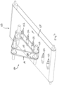
- the conveyor device 09 consists of the conveyor belt 07 and the conveyor belt 08.
- the conveyor belt 08 in turn consists of two conveyor belts 16 and 17 which are arranged at a distance and which come into engagement with the wrapped dough products 02 eccentrically. Due to the distance between the two conveyor belts 16 and 17, the dough products 02 are centered between the two conveyor belts 16 and 17.
Landscapes
- Engineering & Computer Science (AREA)
- Life Sciences & Earth Sciences (AREA)
- Food Science & Technology (AREA)
- Mechanical Engineering (AREA)
- Manufacturing And Processing Devices For Dough (AREA)
Description
- Die Erfindung betrifft ein Verfahren zum Ausrichten von gewickelten Teigprodukten in einer definierten Schlusslage nach dem Oberbegriff des Anspruchs 1. Weiter betrifft die Erfindung eine Vorrichtung zur Durchführung des erfindungsgemäßen Verfahrens.
- Eine Vorrichtung zum Rollen von Teig in eine längliche Form, beispielsweise zur Herstellung von Stangenbrot, ist aus der
NL 8204931 A
Aus derWO 2012/062267 A2 sind ein gattungsgemäßes Verfahren und eine gattungsgemäße Vorrichtung zum Ausrichten von gewickelten Teigprodukten in einer definierten Schlusslage bekannt. Dieses Verfahren wird insbesondere dazu eingesetzt, um aus trapezförmigen Teigstücken gewickelte Teigprodukte, beispielsweise Croissants, vor dem Backen in einer definierten Schlusslage auszurichten. Das Verfahren beruht dabei auf dem Grundgedanken, dass die gewickelten Teigprodukte nach dem Durchlaufen der Wickelstrecke von einer translatorischen Anfangsgeschwindigkeit auf eine geänderte translatorische Zwischengeschwindigkeit abgebremst werden. Dazu durchlaufen die gewickelten Teigprodukte eine Bremsstrecke. Durch das Abbremsen der gewickelten Teigprodukte wirkt auf die Teigprodukte ein Bremsmoment, durch das die Teigprodukte in eine Abrollbewegung versetzt werden. Durch dieses Abrollen der Teigprodukte rollen diese mit einem Drehsinn, der der Wickelrichtung von innen nach außen des gewickelten Teigprodukts entspricht, auf einer Unterlage ab. Beim Erreichen der Schlusslage, bei der der Schluss des Teigprodukts auf der Unterlage anliegt, wird die Abrollbewegung durch den vom Schluss verursachten Rollwiderstand gestoppt. Im Ergebnis kann also durch das Abbremsen der Teigprodukte und das damit verbundene Abrollen der Teigprodukte auf der Unterlage ohne Weiteres eine definierte Schlusslage erreicht werden, bei der der Schluss des Teigprodukts auf der Unterlage anliegt. - Das Ausrichten der Teigprodukte in der definierten Schlusslage durch das Abbremsen entlang der Bremsstrecke erfordert die Einstellung relativ exakter Randbedingungen hinsichtlich der Anfangs- und Endgeschwindigkeit des Teigprodukts, um zu verhindern, dass das Teigprodukt über den Schluss hinwegrollt, wenn beispielsweise das durch das Bremsmoment erzeugte Antriebsmoment zu groß ist. Umgekehrt darf das vom Bremsmoment erzeugte Antriebsmoment auch nicht zu klein sein, da ansonsten die durch das Abbremsen bewirkte Abrollbewegung nicht ausreicht, um die definierte Schlusslage zu erreichen. Problematisch ist es dabei, dass die Randbedingungen des Abbremsens entlang der Bremsstrecke bisher nicht frei gewählt werden können. Insbesondere ist die Anfangsgeschwindigkeit des Teigprödukts beim Verlassen der Wickelstrecke sehr stark von der jeweils gewünschten Produktionsgeschwindigkeit abhängig, da die Teigprodukte bei höheren Taktfrequenzen mit immer höheren Geschwindigkeiten durch die Wickelstrecke transportiert werden. Außerdem führen die höheren Taktfrequenzen dazu, dass auch die Rotationsgeschwindigkeit der Teigstücke beim Verlassen der Wickelstrecke immer höher ist. Diese starke Rotation der Teigstücke beim Verlassen der Wickelstrecke führt außerdem zu einer Taumelbewegung der Teigstücke, die ein definiertes Abbremsen der Teigstücke im unmittelbaren Anschluss an das Verlassen der Wickelstrecke vielfach unmöglich macht.
- Ausgehend von diesem Stand der Technik ist es deshalb die Aufgabe der vorliegenden Erfindung, ein Verfahren und eine Vorrichtung zum Ausrichten von gewickelten Teigprodukten durch Abbremsen in einer Bremsstrecke vorzuschlagen, wobei auch sehr hohe Taktfrequenzen ermöglicht werden. Insbesondere soll auch die hohe Ausschussrate, wie sie beim Betrieb bekannter Vorrichtungen bei hohen Taktfrequenzen auftritt, verringert werden.
- Diese Aufgabe wird durch ein Verfahren und eine Vorrichtung nach der Lehre der beiden unabhängigen Hauptansprüche gelöst.
- Vorteilhafte Ausführungsformen der Erfindung sind Gegenstand der Unteransprüche.
- Das erfindungsgemäße Verfahren beruht auf dem Grundgedanken, dass zwischen dem Ende der Wickelstrecke und vor Beginn der Bremsstrecke eine zusätzliche Kontrollstrecke vorgesehen ist, die von den gewickelten Teigprodukten durchlaufen wird. In der Kontrollstrecke ist es dabei vorgesehen, dass zwei umlaufend angetriebene Förderbänder im Anschluss an die Wickelstrecke am Teigprodukt in Eingriff gebracht werden und die translatorische Fördergeschwindigkeit der gewickelten Teigprodukte und/oder die Rotationsgeschwindigkeit der gewickelten Teigprodukte verändert und auf einen vorgegebenen Sollwert eingestellt werden. Insbesondere ist es dadurch möglich, die am Ende der Wickelstrecke wartende translatorische Fördergeschwindigkeit der gewickelten Teigprodukte bzw. die Rotationsgeschwindigkeit der gewickelten Teigprodukte, die sehr stark von der jeweiligen Produktionsfrequenz beim Wickeln abhängt, in einer Weise zu verändern und einzustellen, dass anschließend die in der Kontrollstrecke eingestellten Randbedingungen ein Erreichen der definierten Schlusslage beim Abbremsen der Teigprodukte in der Bremsstrecke ermöglichen.
- Von sehr großer Bedeutung für das korrekte Abbremsen der Teigprodukte in der Bremsstrecke und das dadurch erreichte Einstellen der definierten Schlusslage mit einem bestimmten Bereich ist die Rotationsgeschwindigkeit der gewickelten Teigprodukte. Gerade diese Rotationsgeschwindigkeit der gewickelten Teigprodukte wird durch eine Erhöhung der Taktfrequenz in der Wickelstrecke stark erhöht, was jedoch das korrekte Abbremsen der Teigprodukte in der Bremsstrecke zum Einstellen der definierten Schlusslage erheblich erschwert. Denn die gewickelten Teigprodukte verlassen bisher bei hohen Taktfrequenzen die Wickeleinrichtung mit unkontrollierbaren Taumelbewegungen. Es ist deshalb besonders vorteilhaft, wenn die Rotationsgeschwindigkeit der gewickelten Teigprodukte in der Kontrollstrecke abgebremst wird, um die für das Abbremsen beim Einstellen der definierten Schlusslage in der Bremsstrecke mögliche maximale Anfangsgeschwindigkeit nicht zu überschreiten.
- Wie stark die Rotationsgeschwindigkeit der gewickelten Teigprodukte in der Kontrollstrecke abgebremst wird, ist abhängig von der Produktionsqualität während des Bremsens in der Bremsstrecke. Besonders vorteilhaft ist es, wenn die Rotationsgeschwindigkeit der gewickelten Teigprodukte in der Kontrollstrecke auf einen Wert Null abgebremst wird, d.h. die Teigprodukte am Ende der Kontrollstrecke keine Eigenrotation mehr aufweisen.
- Alternativ dazu kann die Rotationsgeschwindigkeit des gewickelten Teigprodukts in der Kontrollstrecke auch in die Gegenrichtung umgekehrt werden, so dass diese Rotationsbewegung in Gegenrichtung gerade der Rotationsbewegung beim Abbremsen in der Bremsstrecke entspricht. Dadurch kann das erforderliche Bremsmoment signifikant herabgesetzt werden.
- In welcher Weise die gewickelten Teigprodukte in der Bremsstrecke abgebremst werden, ist grundsätzlich beliebig. Besonders einfach kann dies bei der erfindungsgemäß vorgesehenen Verwendung einer Kontrollstrecke dadurch erfolgen, dass die Teigprodukte von einem ersten umlaufend angetriebenen Förderband mit einer ersten Fördergeschwindigkeit auf ein zweites umlaufend angetriebenes Förderband mit einer zweiten Fördergeschwindigkeit übergeben werden. Durch den entsprechenden Unterschied zwischen der ersten Fördergeschwindigkeit und der zweiten Fördergeschwindigkeit können die gewickelten Teigprodukte durch diese Übergabe abgebremst und dadurch in die gewünschte Abrollbewegung versetzt werden. Um die gewickelten Teigprodukte bei der Übergabe vom ersten Förderband auf das zweite Förderband leichter in die Abrollbewegung versetzen zu können, ist es besonders vorteilhaft, wenn die gewickelten Teigprodukte in der Bremsstrecke bei der Übergabe vom ersten Förderband auf das zweite Förderband vertikal nach unten versetzt werden. Durch diese kleine Fallbewegung der gewickelten Teigprodukte bei der Übergabe vom ersten Förderband auf das zweite Förderband wird der Abrollimpuls vergrößert, und es werden reproduzierbare Prozessbedingungen geschaffen. Die erfindungsgemäße Vorrichtung zur Durchführung des erfindungsgemäßen Verfahrens beim Ausrichten von gewickelten Teigprodukten umfasst in gattungsgemäßer Weise eine Wickelstrecke und eine Bremsstrecke. In der Wickelstrecke werden die Teigstücke zu Teigprodukten gewickelt. In der nachgeordneten Bremsstrecke können die gewickelten Teigprodukte durch entsprechendes Abbremsen in eine Abrollbewegung versetzt werden, um die definierte Schlusslage, in der der Schluss des Teigprodukts an der Unterlage anliegt, zu ermöglichen. Die erfindungsgemäße Vorrichtung ist durch eine Fördereinrichtung charakterisiert, die eine Kontrollstrecke zwischen der Wickelstrecke und der Bremsstrecke bildet. Die Fördereinrichtung ist dabei dadurch gekennzeichnet, dass die Fördereinrichtung aus zwei umlaufend angetriebenen Förderbändern gebildet ist und die translatorische Fördergeschwindigkeit der gewickelten Teigprodukte bzw. die Rotationsgeschwindigkeit der gewickelten Teigprodukte beim Durchlauf der Kontrollstrecke zwischen der Wickelstrecke und der Bremsstrecke verändert werden kann.
- Besonders einfach kann das erste Förderband von unten an den gewickelten Teigprodukten zum Eingriff kommen und das zweite Förderband von oben an den gewickelten Teigprodukten zum Eingriff kommen. Durch geeignete Einstellung der Umlaufgeschwindigkeit des ersten Förderbands relativ zur Umlaufgeschwindigkeit des zweiten Förderbands kann dann durch den gleichzeitigen Eingriff der beiden Förderbänder die translatorische Fördergeschwindigkeit des Teigprodukts bzw. die Rotationsgeschwindigkeit des gewickelten Teigprodukts in der gewünschten Weise verändert und gegebenenfalls auf einen vorgegebenen Sollwert eingestellt werden.
- Um eine einfache Justierung der in der Kontrollstrecke eingestellten translatorischen Fördergeschwindigkeit bzw. Rotationsgeschwindigkeit des gewickelten Teigprodukts zu ermöglichen, ist es besonders vorteilhaft, wenn die Umlaufgeschwindigkeit des ersten Förderbands und/oder die Umlaufgeschwindigkeit des zweiten Förderbands unabhängig voneinander einstellbar sind.
- Beim Wickeln der Teigstücke kann es vorkommen, dass die gewickelten Teigprodukte aus der gewünschten Mittellage nach rechts bzw. nach links versetzt werden. Diese Lagefehler der gewickelten Teigprodukte sind für die nachfolgenden Produktionsstufen von Nachteil, beispielsweise wenn die gewickelten Teigprodukte nachfolgend gebogen werden sollen, um traditionelle Croissants zu bilden. Um diese Lagefehler in einfacher Weise ohne großen zusätzlichen Aufwand korrigieren zu können, ist es besonders vorteilhaft, wenn das obere Förderband der Fördereinrichtung aus mindestens zwei zueinander beabstandet angeordneten Förderriemen besteht, wobei die beiden Förderriemen jeweils außermittig am gewickelten Teigstück zur Anlage kommen. Durch die beiden beabstandet angeordneten Förderriemen wird eine Zentrierbewegung der gewickelten Teigprodukte während des Durchlaufs der Kontrollstrecke erreicht. Liegen nämlich die gewickelten Teigstücke mit einem Lagefehler etwas zu weit links bzw. etwas zu weit rechts von der gewünschten Mittellinie, so führt die daraus resultierende Höhendifferenz auf der rechten bzw. linken Seite zu den jeweils anliegenden Förderriemen dazu, dass die gewickelten Teigstücke in Richtung der gewünschten Mittellage verschoben werden. Um die Kontrollstrecke und die dahinter angeordnete Bremsstrecke mit möglichst einfachen Mitteln konstruktiv realisieren zu können, ist es besonders vorteilhaft, wenn zur Bildung der Bremsstrecke hinter dem unteren Förderband der Kontrollstrecke ein Förderband mit einer geringeren Fördergeschwindigkeit angeordnet ist. Die Bremsstrecke wird dann dadurch gebildet, dass die gewickelten Teigprodukte von dem unteren Förderband der Kontrollstrecke auf das dahinterliegende Förderband mit der geringeren Fördergeschwindigkeit übergeben werden. Aufgrund der Differenz zwischen den Fördergeschwindigkeiten bei der Übergabe von dem unteren Förderband der Kontrollstrecke auf das dahinter angeordnete Förderband werden die Teigprodukte abgebremst und durch das dadurch bewirkte Bremsmoment in die gewünschte Abrollbewegung versetzt.
- Um den Abrollimpuls noch zu verstärken, ist es besonders vorteilhaft, wenn zwischen dem unteren Förderband der Kontrollstrecke und dem dahinter angeordneten Förderband der Bremsstrecke ein vertikaler Höhenversatz nach unten vorgesehen ist, so dass die Teigprodukte bei der Übergabe von dem unteren Förderband der Kontrollstrecke auf das dahinterliegende Förderband ein kleines Stück nach unten fallen.
- Eine Ausführungsform der Erfindung ist den Zeichnungen schematisiert dargestellt und wird nachfolgend beispielhaft erläutert.
- Es zeigen:
- Fig. 1
- eine schematisiert dargestellte Anlage zum Wickeln und Ausrichten von Teigprodukten in einer definierten Schlusslage in seitlicher Ansicht;
- Fig. 2
- eine als Kontrollstrecke zwischen der Wickelstrecke und der Bremsstrecke der Anlage gemäß
Fig. 1 angeordnete Fördereinrichtung in perspektivischer Ansicht von oben. -
Fig. 1 zeigt eine Vorrichtung 01 zum Wickeln und Ausrichten von Teigprodukten 02 in einer definierten Schlusslage. Die Anlage 01 umfasst eine Wickelstrecke 03, in der die Teigprodukte 02 durch Wickeln von dreieckförmigen oder trapezförmigen Teigstücken hergestellt werden. In der Wickelstrecke 03 werden die Teigprodukte 02 auf einem Förderband 04 in Förderrichtung transportiert, wobei die Teigprodukte 02 mit ihrem oberen Scheidepunkt an einer feststehenden Wickelplatte 05 anliegen. Im Ergebnis bedeutet dies, dass die Teigprodukte 02 an ihrem unteren Scheitelpunkt mit einer Fördergeschwindigkeit bewegt werden, die der Umlaufgeschwindigkeit v1 des Förderbands 04 entspricht, wohingegen der obere Scheitelpunkt der Teigprodukte 02 die Geschwindigkeit Null aufweist. Durch die Geschwindigkeitsdifferenz zwischen der Wickelplatte 05 und dem Förderband 04 werden die Teigprodukte 02 in eine rotierende Wickelbewegung versetzt, so dass die Teigprodukte 02 am Ende der Wickelstrecke 03 eine translatorische Fördergeschwindigkeit v1res aufweisen. An die Wickelstrecke 03 schließt sich eine Kontrollstrecke 06 an, die aus einem unteren Förderband 07 und einem oberen Förderband 08 gebildet ist. Das Förderband 07 läuft dabei mit einer Fördergeschwindigkeit v2 um, wobei v2 gerade der translatorischen Fördergeschwindigkeit vires der Teigprodukte 02 am Ende der Wickelstrecke 03 entspricht. Die Umlaufgeschwindigkeit des Förderbands 08 kann variabel eingestellt werden, so dass sich abhängig von der Umlaufgeschwindigkeit v3 des Förderbands 08 relativ zur Umlaufgeschwindigkeit v2 des Förderbands 07 eine entsprechende Rotation der Teigprodukte 02 ergibt. Entspricht die Umlaufgeschwindigkeit v3 des Förderbands 08 gerade der Umlaufgeschwindigkeit v2 des Förderbands 07, so weisen die Teigprodukte 02 keine Rotationsgeschwindigkeit mehr auf und werden mit einer translatorischen Fördergeschwindigkeit von v2=v3 in Förderrichtung bewegt. Wird v3 etwas kleiner als v2 gewählt, so rotieren die Teigprodukte 02 entgegen dem Uhrzeigersinn, wohingegen für den Fall, dass v3 etwas größer als v2 ist, die Teigprodukte 02 im Uhrzeigersinn rotieren. Im Ergebnis kann so die Rotationsgeschwindigkeit der Teigprodukte 02 durch Wahl des Verhältnisses von v2:v3 problemlos eingestellt werden. Die translatorische Fördergeschwindigkeit der Teigprodukte 02 kann in gleicher Weise durch Wahl von v2 bzw. v3 eingestellt werden. - Im Ergebnis wird es durch die von den Förderbändern 07 und 08 gebildete Fördereinrichtung 09, die die Kontrollstrecke 06 bildet, möglich, dass die aus der Wickelstrecke 03 kommenden Teigprodukte 02 in ihrer translatorischen Fördergeschwindigkeit und ihrer Rotationsgeschwindigkeit exakt eingestellt werden, so dass die Bedingungen für das Ausrichten der Teigprodukte 02 in der nachfolgend angeordneten Bremsstrecke 10 optimiert sind.
- In der Anlage 01 ist die Bremsstrecke 10 durch den Übergang vom Förderband 07 auf ein nachgeordnetes Förderband 11 realisiert. Das Förderband 11 wird dabei mit einer Umlaufgeschwindigkeit v4 angetrieben, die kleiner ist als die Umlaufgeschwindigkeit v2 des Förderbands 07. Durch diesen Geschwindigkeitsunterschied zwischen den Förderbändern 07 und 11 werden die Teigprodukte 02 bei der Übergabe vom Förderband 07 auf das Förderband 11 translatorisch abgebremst und zugleich durch das Bremsmoment in eine Abrollbewegung versetzt. Diese Abrollbewegung wird noch dadurch verstärkt, dass zwischen dem Förderband 11 und dem Förderband 07 ein kleiner vertikaler Höhenversatz vorgesehen ist, durch den die Teigprodukte beim Übergang vom Förderband 07 auf das Förderband 11 ein Stück weit herunterfallen. Durch die durch das Bremsmoment verursachte Abrollbewegung rollen die Teigprodukte 02 auf dem Förderband 11 ein Stück weit im Uhrzeigersinn ab, bis der vom Schluss der Teigprodukte verursachte Rollenwiderstand das Abrollen in der definierten Schlusslage, bei der der Schluss des Teigprodukts an der Unterlage, nämlich dem Förderband 11 anliegt, abstoppt. Im Ergebnis wird also das Teigprodukt 02 bei der Übergabe vom Förderband 07 auf das Förderband 11 so in Rotationsbewegung versetzt, bis es die definierte Schlusslage erreicht hat, bei der der Schluss durch die in Uhrzeigerrichtung gerichtete Abrollbewegung auf der Oberseite des Förderbands 11 anliegt.
- Anschließend durchlaufen die Teigprodukte 02 eine Ausrichtstrecke 12, die im Zusammenwirken des Förderbands 11 mit einem Förderband 13 gebildet ist. Das Förderband 13 wird dabei mit einer Umlaufgeschwindigkeit v5 angetrieben, die etwas größer ist als die Umlaufgeschwindigkeit v4 des Förderbands 11. Durch diese Geschwindigkeitsdifferenz zwischen v5 und v4 wird erreicht, dass die Teigprodukte 02 entlang der Ausrichtstrecke 12 um ungefähr 45° im Uhrzeigersinn weitergedreht werden und damit mit ihrem Schluss auf der Oberseite des Förderbands 11 anliegen. An die Ausrichtstrecke 12 schließt sich eine Flachdrückstrecke 14 an. Die Flachdrückstrecke 14 ist aus dem Förderband 11 in Zusammenwirken mit einem Förderband 15 gebildet. Der vertikale Abstand Y zwischen dem Förderband 11 und dem Förderband 15 ist dabei kleiner als der Durchmesser X der Teigprodukte 02, so dass die Teigprodukte 02 in der Flachdrückstrecke 14 vertikal zusammengedrückt werden, um die Lage des Schlusses in der definierten Schlusslage zu sichern.
-
Fig. 2 zeigt die Kontrollstrecke 06 mit der Fördereinrichtung 09 in perspektivischer Ansicht von schräg oben. Die Fördereinrichtung 09 besteht aus dem Förderband 07 und dem Förderband 08. Das Förderband 08 seinerseits besteht aus zwei beabstandet angeordneten Förderriemen 16 und 17, die außermittig an den gewickelten Teigprodukten 02 zum Eingriff kommen. Durch den Abstand der beiden Förderriemen 16 und 17 wird eine Zentrierung der Teigprodukte 02 mittig zwischen den beiden Förderriemen 16 und 17 erreicht.
Claims (12)
- Verfahren zum Ausrichten von gewickelten Teigprodukten (02) in einer definierten Schlusslage, wobei das Teigprodukt (02) durch Wickeln eines dreieckförmigen oder trapezförmigen Teigstücks entlang einer Wickelstrecke (03) hergestellt ist, und wobei das Teigprodukt (02) von der Basis des Teigstücks her beginnend gewickelt ist, und wobei das schmalere Ende des Teigstücks einen außen am Umfang des Teigprodukts (02) überstehenden Schluss bildet, und wobei die Schlusslage des Teigprodukts (02) durch eine bestimmte Lage des außen überstehenden Schlusses definiert ist, und wobei das gewickelte Teigprodukt (02) entlang einer Bremsstrecke (10) von einer translatorischen Anfangsgeschwindigkeit auf eine translatorische Endgeschwindigkeit abgebremst wird, und wobei das daraus resultierende Bremsmoment als Antriebsmoment für eine Abrollbewegung des Teigprodukts (02) genutzt wird, um dadurch ein Abrollen des Teigprodukts (02) auf einer Unterlage zu bewirken, wobei der Drehsinn der Abrollbewegung des Teigprodukts (02) der Wickelrichtung von innen nach außen des gewickelten Teigprodukts (02) entspricht, und wobei die Abrollbewegung bei Erreichen der definierten Schlusslage, bei der der Schluss des Teigprodukts (02) an der Unterlage anliegt, durch den vom Schluss verursachten Rollwiderstand gestoppt wird,
dadurch gekennzeichnet,
dass das gewickelte Teigprodukt (02) zwischen dem Ende der Wickelstrecke (03) und vor Beginn der Bremsstrecke (10) eine Kontrollstrecke (06) durchläuft, wobei in der Kontrollstrecke (06) zwei umlaufend angetriebene Förderbänder (07, 08) im Anschluss an die Wickelstrecke (03) am Teigprodukt (02) in Eingriff gebracht werden, und wobei in der Kontrollstrecke (06) die translatorische Fördergeschwindigkeit des gewickelten Teigprodukts (02) und/oder die Rotationsgeschwindigkeit des gewickelten Teigprodukts (02) verändert und auf einen vorgegebenen Sollwert eingestellt werden. - Verfahren nach Anspruch 1,
dadurch gekennzeichnet,
dass die Rotationsgeschwindigkeit des gewickelten Teigprodukts (02) in der Kontrollstrecke (06) abgebremst wird. - Verfahren nach Anspruch 2,
dadurch gekennzeichnet,
dass die Rotationsgeschwindigkeit des gewickelten Teigprodukts (02) in der Kontrollstrecke (06) auf Null abgebremst wird. - Verfahren nach Anspruch 2,
dadurch gekennzeichnet,
dass die Rotationsgeschwindigkeit des gewickelten Teigprodukts (02) in der Kontrollstrecke (06) in die Gegenrichtung umgekehrt wird, wobei die Rotationsbewegung in Gegenrichtung der Rotationsbewegung beim Abbremsen in der Bremsstrecke (10) entspricht. - Verfahren nach einem der Ansprüche 1 bis 4,
dadurch gekennzeichnet,
dass das gewickelte Teigprodukt (02) in der Bremsstrecke (10) durch Übergabe von einem ersten umlaufend angetriebenen Förderband (07) mit einer ersten Fördergeschwindigkeit auf ein zweites umlaufend angetriebenes Förderband (11) mit einer zweiten Fördergeschwindigkeit abgebremst und dadurch in die gewünschte Abrollbewegung versetzt wird. - Verfahren nach Anspruch 5,
dadurch gekennzeichnet,
dass das gewickelte Teigprodukt (02) in der Bremsstrecke (10) bei der Übergabe vom ersten Förderband (07) auf das zweite Förderband (11) vertikal nach unten versetzt wird. - Vorrichtung (01) zur Durchführung eines Verfahrens zum Ausrichten von gewickelten Teigprodukten (02) in einer definierten Schlusslage, wobei das Teigprodukt (02) durch Wickeln eines dreieckförmigen oder trapezförmigen Teigstücks entlang einer Wickelstrecke (03) hergestellt ist, und wobei das Teigprodukt (02) von der Basis des Teigstücks her beginnend gewickelt ist, und wobei das schmalere Ende des Teigstücks einen außen am Umfang des Teigprodukts (02) überstehenden Schluss bildet, und wobei die Schlusslage des Teigprodukts (02) durch eine bestimmte Lage des außen überstehenden Schlusses definiert ist, und wobei das gewickelte Teigprodukt (02) entlang einer Bremsstrecke (10) von einer translatorischen Anfangsgeschwindigkeit auf eine translatorische Endgeschwindigkeit abgebremst wird, und wobei das daraus resultierende Bremsmoment als Antriebsmoment für eine Abrollbewegung des Teigprodukts (02) genutzt wird, um dadurch ein Abrollen des Teigprodukts (02) auf einer Unterlage zu bewirken, wobei der Drehsinn der Abrollbewegung des Teigprodukts (02) der Wickelrichtung von innen nach außen des gewickelten Teigprodukts (02) entspricht, und wobei die Abrollbewegung bei Erreichen der definierten Schlusslage, bei der der Schluss des Teigprodukts (02) an der Unterlage anliegt, durch den vom Schluss verursachten Rollwiderstand gestoppt wird, wobei das gewickelte Teigprodukt (02) zwischen dem Ende der Wickelstrecke (03) und vor Beginn der Bremsstrecke (10) eine Kontrollstrecke (06) durchläuft, wobei in der Kontrollstrecke (06) zwei umlaufend angetriebene Förderbänder (07, 08) im Anschluss an die Wickelstrecke (03) am Teigprodukt (02) in Eingriff gebracht werden, und wobei in der Kontrollstrecke (06) die translatorische Fördergeschwindigkeit des gewickelten Teigprodukts (02) und/oder die Rotationsgeschwindigkeit des gewickelten Teigprodukts (02) auf einen vorgegebenen Sollwert eingestellt werden,wobei die Vorrichtung aufweist: die Wickelstrecke (03), in der Teigstücke zu Teigprodukten (02) gewickelt werden, und die Bremsstrecke (10), in der die Teigprodukte (02) in einer definierten Schlusslage abgebremst werden,dadurch gekennzeichnet,dass die Vorrichtung (01) zwischen der Wickelstrecke (03) und der Bremsstrecke (10) eine Fördereinrichtung (09) zur Bildung der Kontrollstrecke (06) aufweist, wobei mit der Fördereinrichtung (09) die translatorische Fördergeschwindigkeit des gewickelten Teigprodukts (02) und/oder die Rotationsgeschwindigkeit des gewickelten Teigprodukts (02) in der Kontrollstrecke (06) zwischen der Wickelstrecke (03) und der Bremsstrecke (10) verändert werden können, und wobei die Fördereinrichtung (09) aus zwei umlaufend angetriebenen Förderbändern (07,08) gebildet ist.
- Vorrichtung nach Anspruch 7,
dadurch gekennzeichnet,
dass das erste Förderband (07) von unten an den gewickelten Teigprodukten (02) zum Eingriff kommt, und das zweite Förderband (08) von oben an den gewickelten Teigprodukten (02) zum Eingriff kommt, wobei die translatorische Fördergeschwindigkeit des gewickelten Teigprodukts (02) und/oder die Rotationsgeschwindigkeit des gewickelten Teigprodukts (02) durch die Einstellung der Umlaufgeschwindigkeit des ersten Förderbands (07) und/oder durch die Einstellung der Umlaufgeschwindigkeit des zweiten Förderbands (08) veränderbar sind. - Vorrichtung nach Anspruch 8,
dadurch gekennzeichnet,
dass die Umlaufgeschwindigkeit des ersten Förderbands (07) und die Umlaufgeschwindigkeit des zweiten Förderbands (08) unabhängig voneinander einstellbar sind. - Vorrichtung nach Anspruch 8 oder 9,
dadurch gekennzeichnet,
dass das obere Förderband (08) der Fördereinrichtung (09) aus zumindest zwei zueinander beabstandet angeordneten Förderriemen (16, 17) besteht, wobei die beiden Förderriemen (16, 17) jeweils außermittig am gewickelten Teigprodukt (02) zur Anlage kommen. - Vorrichtung nach einem der Ansprüche 7 bis 10,
dadurch gekennzeichnet,
dass zur Bildung der Bremsstrecke (10) hinter dem unteren Förderband (07) der Kontrollstrecke (06) ein Förderband (11) mit einer geringeren Fördergeschwindigkeit angeordnet ist, wobei die gewickelten Teigprodukte (02) aufgrund der Differenz zwischen den Fördergeschwindigkeiten bei der Übergabe vom unteren Förderband (07) der Kontrollstrecke (06) auf das dahinter angeordnete Förderband (11) der Bremsstrecke (10) abgebremst und dadurch in die gewünschte Abrollbewegung versetzt werden. - Vorrichtung nach einem der Ansprüche 7 bis 11,
dadurch gekennzeichnet,
dass zwischen dem unteren Förderband (07) der Kontrollstrecke (06) und dem dahinter angeordnete Förderband (11) der Bremsstrecke (10) ein vertikaler Höhenversatz nach unten vorgesehen ist.
Applications Claiming Priority (1)
| Application Number | Priority Date | Filing Date | Title |
|---|---|---|---|
| DE102017109925.5A DE102017109925B4 (de) | 2017-05-09 | 2017-05-09 | Verfahren und Vorrichtung zum Ausrichten von gewickelten Teigprodukten entlang einer Bremsstrecke |
Publications (3)
| Publication Number | Publication Date |
|---|---|
| EP3400803A1 EP3400803A1 (de) | 2018-11-14 |
| EP3400803B1 EP3400803B1 (de) | 2020-05-13 |
| EP3400803B2 true EP3400803B2 (de) | 2023-03-15 |
Family
ID=61827540
Family Applications (1)
| Application Number | Title | Priority Date | Filing Date |
|---|---|---|---|
| EP18164109.3A Active EP3400803B2 (de) | 2017-05-09 | 2018-03-27 | Verfahren und vorrichtung zum ausrichten von gewickelten teigprodukten entlang einer bremsstrecke |
Country Status (3)
| Country | Link |
|---|---|
| US (1) | US20180325123A1 (de) |
| EP (1) | EP3400803B2 (de) |
| DE (1) | DE102017109925B4 (de) |
Families Citing this family (5)
| Publication number | Priority date | Publication date | Assignee | Title |
|---|---|---|---|---|
| CN112203517B (zh) * | 2018-05-31 | 2021-08-27 | 雷恩自动机株式会社 | 食品原料片的卷成形装置及其方法 |
| CN110202371B (zh) * | 2019-06-20 | 2020-05-12 | 东莞市智赢智能装备有限公司 | 双组带式齿轮流水线式机器人系统 |
| CN113303346A (zh) * | 2021-05-10 | 2021-08-27 | 广东顺德赛驰科技有限公司 | 球形物旋转定向装置及具有该装置的面团定向机 |
| DE102023102125A1 (de) | 2023-01-30 | 2024-08-01 | Fritsch Bakery Technologies GmbH & Co. KG | Teigverarbeitungsvorrichtung mit schwenkbaren Führungselementen |
| EP4678005A1 (de) * | 2024-07-12 | 2026-01-14 | Robotica & Microtecnica S.n.c. di Zamboni Roberto & C. | Maschine zum aufrollen von lebensmittelteigstücken |
Citations (3)
| Publication number | Priority date | Publication date | Assignee | Title |
|---|---|---|---|---|
| EP1342415A2 (de) † | 2002-03-06 | 2003-09-10 | VORTEX SYSTEMS S.r.L. | Vorrichtung zum Falten von Hörnchen |
| NL1025310C2 (nl) † | 2004-01-23 | 2005-07-26 | Rademaker B V | Inrichting en werkwijze voor het positioneren van croissants. |
| DE202008003923U1 (de) † | 2007-06-25 | 2008-10-16 | Fritsch Gmbh | System zum schlusslagengenauen Ausrichten gewickelter Teigstücke |
Family Cites Families (5)
| Publication number | Priority date | Publication date | Assignee | Title |
|---|---|---|---|---|
| NL8204931A (nl) * | 1982-12-21 | 1984-07-16 | Werner & Pfleiderer Haton Bv | Langrolinrichting. |
| DE4402346A1 (de) * | 1994-01-27 | 1995-08-03 | Fritsch A Gmbh & Co Kg | Verfahren und Vorrichtung zum Aufwickeln eines Teigbandes |
| JP2750812B2 (ja) * | 1994-03-04 | 1998-05-13 | レオン自動機株式会社 | 棒状パン生地の成形方法および装置 |
| EP1747724A3 (de) * | 2005-07-27 | 2008-01-23 | Fritsch GmbH | Verfahren und Vorrichtung zum schlusslagengenauen Ausrichten von gewickelten Teigprodukten |
| DE102011011049B4 (de) * | 2010-11-09 | 2015-03-05 | Fritsch Gmbh | Verfahren und Vorrichtung zum Ausrichten von gewickelten Teigprodukten in einer definierten Schlusslage |
-
2017
- 2017-05-09 DE DE102017109925.5A patent/DE102017109925B4/de active Active
-
2018
- 2018-03-27 EP EP18164109.3A patent/EP3400803B2/de active Active
- 2018-05-04 US US15/971,418 patent/US20180325123A1/en not_active Abandoned
Patent Citations (3)
| Publication number | Priority date | Publication date | Assignee | Title |
|---|---|---|---|---|
| EP1342415A2 (de) † | 2002-03-06 | 2003-09-10 | VORTEX SYSTEMS S.r.L. | Vorrichtung zum Falten von Hörnchen |
| NL1025310C2 (nl) † | 2004-01-23 | 2005-07-26 | Rademaker B V | Inrichting en werkwijze voor het positioneren van croissants. |
| DE202008003923U1 (de) † | 2007-06-25 | 2008-10-16 | Fritsch Gmbh | System zum schlusslagengenauen Ausrichten gewickelter Teigstücke |
Also Published As
| Publication number | Publication date |
|---|---|
| DE102017109925A1 (de) | 2018-11-15 |
| EP3400803B1 (de) | 2020-05-13 |
| EP3400803A1 (de) | 2018-11-14 |
| US20180325123A1 (en) | 2018-11-15 |
| DE102017109925B4 (de) | 2023-10-19 |
Similar Documents
| Publication | Publication Date | Title |
|---|---|---|
| EP3400803B2 (de) | Verfahren und vorrichtung zum ausrichten von gewickelten teigprodukten entlang einer bremsstrecke | |
| DE102011011049B4 (de) | Verfahren und Vorrichtung zum Ausrichten von gewickelten Teigprodukten in einer definierten Schlusslage | |
| DE102015118200A1 (de) | Pressenvorrichtung mit einstellmechanismus | |
| DE2813100C2 (de) | ||
| EP2939965B1 (de) | Schiebevorrichtung für eine palettiervorrichtung mit einem schieber, widerlager und mit zwei ausrichtdrücker | |
| DE3903701C1 (de) | ||
| DE60025702T2 (de) | Profilwalzen in einer revolverstanzpresse | |
| DE3316712A1 (de) | Verfahren zur praezisionsherstellung von eng gewickelten schraubenzugfedern | |
| WO2019081516A1 (de) | Verfahren zum herstellen einer elektrischen spule und wickelvorrichtung | |
| EP3905494A1 (de) | Biegevorrichtung und biegeverfahren zum zweidimensionalen biegen eines elektrischen leiters | |
| DE3611160C2 (de) | ||
| AT326065B (de) | Vorrichtung zum u- bzw. sichelförmigem biegen von langgewirkten backwarenrohlingen, insbesondere kipferlrohlingen | |
| EP0408832A2 (de) | Vorrichtung zum Erzeugen von Drilleitern | |
| DE69311473T2 (de) | Verfahren und Vorrichtung zum Bewickeln von Ringkernspulen | |
| WO2019243050A1 (de) | Biegemaschine zur herstellung von biegeteilen aus flachmaterial | |
| DE1502717C3 (de) | Vorrichtung zur Steuerung des intermittierenden Antriebes eines Rundschalttisches mit einem Malteserkreuz-Getriebe | |
| DE2907839C2 (de) | Querfördervorrichtung für im Querschnitt eckige Knüppel od. dgl. | |
| DE19649839C2 (de) | Vorrichtung und Verfahren zur Herstellung von Rohbrezeln | |
| DE102021108271A1 (de) | Drahtformvorrichtung | |
| EP3323527B1 (de) | Verfahren und vorrichtung zur verdickung des randes eines blechkörpers | |
| DE2543567C3 (de) | Übergabevorrichtung zum gleichzeitigen Übergeben vo n Artikeln | |
| DE1959881A1 (de) | Verfahren und Maschine zur vollautomatischen Herstellung von Federstiften mit wellenfoermigem Laengsschlitz | |
| DE2262231A1 (de) | Vorrichtung zum einstanzen von loechern in kunststoffrohre oder dergleichen rohre | |
| DE68905996T2 (de) | Hochgeschwindigkeitsfaltmaschine fuer elastisches bandmaterial. | |
| EP3867038B1 (de) | Korrugator und verfahren zum verändern eines korrugators |
Legal Events
| Date | Code | Title | Description |
|---|---|---|---|
| PUAI | Public reference made under article 153(3) epc to a published international application that has entered the european phase |
Free format text: ORIGINAL CODE: 0009012 |
|
| STAA | Information on the status of an ep patent application or granted ep patent |
Free format text: STATUS: THE APPLICATION HAS BEEN PUBLISHED |
|
| AK | Designated contracting states |
Kind code of ref document: A1 Designated state(s): AL AT BE BG CH CY CZ DE DK EE ES FI FR GB GR HR HU IE IS IT LI LT LU LV MC MK MT NL NO PL PT RO RS SE SI SK SM TR |
|
| AX | Request for extension of the european patent |
Extension state: BA ME |
|
| STAA | Information on the status of an ep patent application or granted ep patent |
Free format text: STATUS: REQUEST FOR EXAMINATION WAS MADE |
|
| 17P | Request for examination filed |
Effective date: 20190220 |
|
| RBV | Designated contracting states (corrected) |
Designated state(s): AL AT BE BG CH CY CZ DE DK EE ES FI FR GB GR HR HU IE IS IT LI LT LU LV MC MK MT NL NO PL PT RO RS SE SI SK SM TR |
|
| GRAP | Despatch of communication of intention to grant a patent |
Free format text: ORIGINAL CODE: EPIDOSNIGR1 |
|
| STAA | Information on the status of an ep patent application or granted ep patent |
Free format text: STATUS: GRANT OF PATENT IS INTENDED |
|
| INTG | Intention to grant announced |
Effective date: 20190712 |
|
| 19U | Interruption of proceedings before grant |
Effective date: 20190701 |
|
| 19W | Proceedings resumed before grant after interruption of proceedings |
Effective date: 20200203 |
|
| GRAJ | Information related to disapproval of communication of intention to grant by the applicant or resumption of examination proceedings by the epo deleted |
Free format text: ORIGINAL CODE: EPIDOSDIGR1 |
|
| GRAP | Despatch of communication of intention to grant a patent |
Free format text: ORIGINAL CODE: EPIDOSNIGR1 |
|
| INTG | Intention to grant announced |
Effective date: 20200213 |
|
| RAP1 | Party data changed (applicant data changed or rights of an application transferred) |
Owner name: FRITSCH BAKERY TECHNOLOGIES GMBH & CO. KG |
|
| GRAS | Grant fee paid |
Free format text: ORIGINAL CODE: EPIDOSNIGR3 |
|
| GRAA | (expected) grant |
Free format text: ORIGINAL CODE: 0009210 |
|
| STAA | Information on the status of an ep patent application or granted ep patent |
Free format text: STATUS: THE PATENT HAS BEEN GRANTED |
|
| AK | Designated contracting states |
Kind code of ref document: B1 Designated state(s): AL AT BE BG CH CY CZ DE DK EE ES FI FR GB GR HR HU IE IS IT LI LT LU LV MC MK MT NL NO PL PT RO RS SE SI SK SM TR |
|
| REG | Reference to a national code |
Ref country code: GB Ref legal event code: FG4D Free format text: NOT ENGLISH |
|
| REG | Reference to a national code |
Ref country code: CH Ref legal event code: EP |
|
| REG | Reference to a national code |
Ref country code: DE Ref legal event code: R096 Ref document number: 502018001389 Country of ref document: DE |
|
| REG | Reference to a national code |
Ref country code: AT Ref legal event code: REF Ref document number: 1269020 Country of ref document: AT Kind code of ref document: T Effective date: 20200615 |
|
| REG | Reference to a national code |
Ref country code: CH Ref legal event code: NV Representative=s name: BOVARD AG PATENT- UND MARKENANWAELTE, CH |
|
| REG | Reference to a national code |
Ref country code: NL Ref legal event code: FP |
|
| REG | Reference to a national code |
Ref country code: LT Ref legal event code: MG4D |
|
| PG25 | Lapsed in a contracting state [announced via postgrant information from national office to epo] |
Ref country code: NO Free format text: LAPSE BECAUSE OF FAILURE TO SUBMIT A TRANSLATION OF THE DESCRIPTION OR TO PAY THE FEE WITHIN THE PRESCRIBED TIME-LIMIT Effective date: 20200813 Ref country code: FI Free format text: LAPSE BECAUSE OF FAILURE TO SUBMIT A TRANSLATION OF THE DESCRIPTION OR TO PAY THE FEE WITHIN THE PRESCRIBED TIME-LIMIT Effective date: 20200513 Ref country code: GR Free format text: LAPSE BECAUSE OF FAILURE TO SUBMIT A TRANSLATION OF THE DESCRIPTION OR TO PAY THE FEE WITHIN THE PRESCRIBED TIME-LIMIT Effective date: 20200814 Ref country code: PT Free format text: LAPSE BECAUSE OF FAILURE TO SUBMIT A TRANSLATION OF THE DESCRIPTION OR TO PAY THE FEE WITHIN THE PRESCRIBED TIME-LIMIT Effective date: 20200914 Ref country code: LT Free format text: LAPSE BECAUSE OF FAILURE TO SUBMIT A TRANSLATION OF THE DESCRIPTION OR TO PAY THE FEE WITHIN THE PRESCRIBED TIME-LIMIT Effective date: 20200513 Ref country code: SE Free format text: LAPSE BECAUSE OF FAILURE TO SUBMIT A TRANSLATION OF THE DESCRIPTION OR TO PAY THE FEE WITHIN THE PRESCRIBED TIME-LIMIT Effective date: 20200513 Ref country code: IS Free format text: LAPSE BECAUSE OF FAILURE TO SUBMIT A TRANSLATION OF THE DESCRIPTION OR TO PAY THE FEE WITHIN THE PRESCRIBED TIME-LIMIT Effective date: 20200913 |
|
| PG25 | Lapsed in a contracting state [announced via postgrant information from national office to epo] |
Ref country code: RS Free format text: LAPSE BECAUSE OF FAILURE TO SUBMIT A TRANSLATION OF THE DESCRIPTION OR TO PAY THE FEE WITHIN THE PRESCRIBED TIME-LIMIT Effective date: 20200513 Ref country code: HR Free format text: LAPSE BECAUSE OF FAILURE TO SUBMIT A TRANSLATION OF THE DESCRIPTION OR TO PAY THE FEE WITHIN THE PRESCRIBED TIME-LIMIT Effective date: 20200513 Ref country code: BG Free format text: LAPSE BECAUSE OF FAILURE TO SUBMIT A TRANSLATION OF THE DESCRIPTION OR TO PAY THE FEE WITHIN THE PRESCRIBED TIME-LIMIT Effective date: 20200813 Ref country code: LV Free format text: LAPSE BECAUSE OF FAILURE TO SUBMIT A TRANSLATION OF THE DESCRIPTION OR TO PAY THE FEE WITHIN THE PRESCRIBED TIME-LIMIT Effective date: 20200513 |
|
| PG25 | Lapsed in a contracting state [announced via postgrant information from national office to epo] |
Ref country code: AL Free format text: LAPSE BECAUSE OF FAILURE TO SUBMIT A TRANSLATION OF THE DESCRIPTION OR TO PAY THE FEE WITHIN THE PRESCRIBED TIME-LIMIT Effective date: 20200513 |
|
| PG25 | Lapsed in a contracting state [announced via postgrant information from national office to epo] |
Ref country code: ES Free format text: LAPSE BECAUSE OF FAILURE TO SUBMIT A TRANSLATION OF THE DESCRIPTION OR TO PAY THE FEE WITHIN THE PRESCRIBED TIME-LIMIT Effective date: 20200513 Ref country code: CZ Free format text: LAPSE BECAUSE OF FAILURE TO SUBMIT A TRANSLATION OF THE DESCRIPTION OR TO PAY THE FEE WITHIN THE PRESCRIBED TIME-LIMIT Effective date: 20200513 Ref country code: RO Free format text: LAPSE BECAUSE OF FAILURE TO SUBMIT A TRANSLATION OF THE DESCRIPTION OR TO PAY THE FEE WITHIN THE PRESCRIBED TIME-LIMIT Effective date: 20200513 Ref country code: SM Free format text: LAPSE BECAUSE OF FAILURE TO SUBMIT A TRANSLATION OF THE DESCRIPTION OR TO PAY THE FEE WITHIN THE PRESCRIBED TIME-LIMIT Effective date: 20200513 Ref country code: EE Free format text: LAPSE BECAUSE OF FAILURE TO SUBMIT A TRANSLATION OF THE DESCRIPTION OR TO PAY THE FEE WITHIN THE PRESCRIBED TIME-LIMIT Effective date: 20200513 Ref country code: DK Free format text: LAPSE BECAUSE OF FAILURE TO SUBMIT A TRANSLATION OF THE DESCRIPTION OR TO PAY THE FEE WITHIN THE PRESCRIBED TIME-LIMIT Effective date: 20200513 |
|
| REG | Reference to a national code |
Ref country code: DE Ref legal event code: R026 Ref document number: 502018001389 Country of ref document: DE |
|
| PLBI | Opposition filed |
Free format text: ORIGINAL CODE: 0009260 |
|
| PG25 | Lapsed in a contracting state [announced via postgrant information from national office to epo] |
Ref country code: PL Free format text: LAPSE BECAUSE OF FAILURE TO SUBMIT A TRANSLATION OF THE DESCRIPTION OR TO PAY THE FEE WITHIN THE PRESCRIBED TIME-LIMIT Effective date: 20200513 Ref country code: SK Free format text: LAPSE BECAUSE OF FAILURE TO SUBMIT A TRANSLATION OF THE DESCRIPTION OR TO PAY THE FEE WITHIN THE PRESCRIBED TIME-LIMIT Effective date: 20200513 |
|
| 26 | Opposition filed |
Opponent name: RADEMAKER B.V. Effective date: 20210209 |
|
| PLAX | Notice of opposition and request to file observation + time limit sent |
Free format text: ORIGINAL CODE: EPIDOSNOBS2 |
|
| PG25 | Lapsed in a contracting state [announced via postgrant information from national office to epo] |
Ref country code: SI Free format text: LAPSE BECAUSE OF FAILURE TO SUBMIT A TRANSLATION OF THE DESCRIPTION OR TO PAY THE FEE WITHIN THE PRESCRIBED TIME-LIMIT Effective date: 20200513 |
|
| PLBB | Reply of patent proprietor to notice(s) of opposition received |
Free format text: ORIGINAL CODE: EPIDOSNOBS3 |
|
| PG25 | Lapsed in a contracting state [announced via postgrant information from national office to epo] |
Ref country code: MC Free format text: LAPSE BECAUSE OF FAILURE TO SUBMIT A TRANSLATION OF THE DESCRIPTION OR TO PAY THE FEE WITHIN THE PRESCRIBED TIME-LIMIT Effective date: 20200513 |
|
| REG | Reference to a national code |
Ref country code: BE Ref legal event code: MM Effective date: 20210331 |
|
| PG25 | Lapsed in a contracting state [announced via postgrant information from national office to epo] |
Ref country code: IE Free format text: LAPSE BECAUSE OF NON-PAYMENT OF DUE FEES Effective date: 20210327 Ref country code: LU Free format text: LAPSE BECAUSE OF NON-PAYMENT OF DUE FEES Effective date: 20210327 |
|
| PLAB | Opposition data, opponent's data or that of the opponent's representative modified |
Free format text: ORIGINAL CODE: 0009299OPPO |
|
| R26 | Opposition filed (corrected) |
Opponent name: RADEMAKER B.V. Effective date: 20210209 |
|
| PLBP | Opposition withdrawn |
Free format text: ORIGINAL CODE: 0009264 |
|
| PG25 | Lapsed in a contracting state [announced via postgrant information from national office to epo] |
Ref country code: BE Free format text: LAPSE BECAUSE OF NON-PAYMENT OF DUE FEES Effective date: 20210331 |
|
| PUAH | Patent maintained in amended form |
Free format text: ORIGINAL CODE: 0009272 |
|
| STAA | Information on the status of an ep patent application or granted ep patent |
Free format text: STATUS: PATENT MAINTAINED AS AMENDED |
|
| 27A | Patent maintained in amended form |
Effective date: 20230315 |
|
| AK | Designated contracting states |
Kind code of ref document: B2 Designated state(s): AL AT BE BG CH CY CZ DE DK EE ES FI FR GB GR HR HU IE IS IT LI LT LU LV MC MK MT NL NO PL PT RO RS SE SI SK SM TR |
|
| REG | Reference to a national code |
Ref country code: DE Ref legal event code: R102 Ref document number: 502018001389 Country of ref document: DE |
|
| REG | Reference to a national code |
Ref country code: NL Ref legal event code: FP |
|
| P01 | Opt-out of the competence of the unified patent court (upc) registered |
Effective date: 20230329 |
|
| PG25 | Lapsed in a contracting state [announced via postgrant information from national office to epo] |
Ref country code: CY Free format text: LAPSE BECAUSE OF FAILURE TO SUBMIT A TRANSLATION OF THE DESCRIPTION OR TO PAY THE FEE WITHIN THE PRESCRIBED TIME-LIMIT Effective date: 20200513 |
|
| PG25 | Lapsed in a contracting state [announced via postgrant information from national office to epo] |
Ref country code: HU Free format text: LAPSE BECAUSE OF FAILURE TO SUBMIT A TRANSLATION OF THE DESCRIPTION OR TO PAY THE FEE WITHIN THE PRESCRIBED TIME-LIMIT; INVALID AB INITIO Effective date: 20180327 |
|
| PG25 | Lapsed in a contracting state [announced via postgrant information from national office to epo] |
Ref country code: MK Free format text: LAPSE BECAUSE OF FAILURE TO SUBMIT A TRANSLATION OF THE DESCRIPTION OR TO PAY THE FEE WITHIN THE PRESCRIBED TIME-LIMIT Effective date: 20200513 |
|
| PG25 | Lapsed in a contracting state [announced via postgrant information from national office to epo] |
Ref country code: TR Free format text: LAPSE BECAUSE OF FAILURE TO SUBMIT A TRANSLATION OF THE DESCRIPTION OR TO PAY THE FEE WITHIN THE PRESCRIBED TIME-LIMIT Effective date: 20200513 |
|
| PG25 | Lapsed in a contracting state [announced via postgrant information from national office to epo] |
Ref country code: MT Free format text: LAPSE BECAUSE OF FAILURE TO SUBMIT A TRANSLATION OF THE DESCRIPTION OR TO PAY THE FEE WITHIN THE PRESCRIBED TIME-LIMIT Effective date: 20200513 |
|
| PGFP | Annual fee paid to national office [announced via postgrant information from national office to epo] |
Ref country code: IT Payment date: 20250331 Year of fee payment: 8 |
|
| PGFP | Annual fee paid to national office [announced via postgrant information from national office to epo] |
Ref country code: CH Payment date: 20250401 Year of fee payment: 8 |
|
| REG | Reference to a national code |
Ref country code: CH Ref legal event code: U11 Free format text: ST27 STATUS EVENT CODE: U-0-0-U10-U11 (AS PROVIDED BY THE NATIONAL OFFICE) Effective date: 20260401 |
|
| PGFP | Annual fee paid to national office [announced via postgrant information from national office to epo] |
Ref country code: GB Payment date: 20260324 Year of fee payment: 9 |
|
| PGFP | Annual fee paid to national office [announced via postgrant information from national office to epo] |
Ref country code: DE Payment date: 20260320 Year of fee payment: 9 |
|
| PGFP | Annual fee paid to national office [announced via postgrant information from national office to epo] |
Ref country code: AT Payment date: 20260319 Year of fee payment: 9 |
|
| PGFP | Annual fee paid to national office [announced via postgrant information from national office to epo] |
Ref country code: NL Payment date: 20260323 Year of fee payment: 9 |
|
| PGFP | Annual fee paid to national office [announced via postgrant information from national office to epo] |
Ref country code: FR Payment date: 20260325 Year of fee payment: 9 |