EP3399298B1 - Machine à fumer pour cigarette électronique - Google Patents
Machine à fumer pour cigarette électronique Download PDFInfo
- Publication number
- EP3399298B1 EP3399298B1 EP16881178.4A EP16881178A EP3399298B1 EP 3399298 B1 EP3399298 B1 EP 3399298B1 EP 16881178 A EP16881178 A EP 16881178A EP 3399298 B1 EP3399298 B1 EP 3399298B1
- Authority
- EP
- European Patent Office
- Prior art keywords
- cigarette
- catcher
- smoking
- electronic cigarette
- housing
- Prior art date
- Legal status (The legal status is an assumption and is not a legal conclusion. Google has not performed a legal analysis and makes no representation as to the accuracy of the status listed.)
- Active
Links
- 230000000391 smoking effect Effects 0.000 title claims description 317
- 239000003571 electronic cigarette Substances 0.000 title claims description 309
- 235000019504 cigarettes Nutrition 0.000 claims description 274
- 238000007789 sealing Methods 0.000 claims description 111
- 230000007246 mechanism Effects 0.000 claims description 80
- 238000003860 storage Methods 0.000 claims description 77
- 238000005303 weighing Methods 0.000 claims description 57
- 238000009423 ventilation Methods 0.000 claims description 43
- 239000000779 smoke Substances 0.000 claims description 36
- 238000004891 communication Methods 0.000 claims description 32
- 230000005540 biological transmission Effects 0.000 claims description 29
- 238000003825 pressing Methods 0.000 claims description 20
- 238000002360 preparation method Methods 0.000 claims description 19
- 230000000149 penetrating effect Effects 0.000 claims description 9
- 238000012546 transfer Methods 0.000 claims description 6
- 238000000034 method Methods 0.000 description 41
- 241000208125 Nicotiana Species 0.000 description 36
- 235000002637 Nicotiana tabacum Nutrition 0.000 description 36
- 230000008569 process Effects 0.000 description 29
- 238000010586 diagram Methods 0.000 description 28
- 238000000889 atomisation Methods 0.000 description 17
- 238000012360 testing method Methods 0.000 description 16
- 238000001514 detection method Methods 0.000 description 15
- 238000009413 insulation Methods 0.000 description 14
- 238000002474 experimental method Methods 0.000 description 13
- 239000000463 material Substances 0.000 description 12
- 230000009471 action Effects 0.000 description 11
- 239000000443 aerosol Substances 0.000 description 9
- 230000008859 change Effects 0.000 description 9
- 239000011152 fibreglass Substances 0.000 description 9
- 230000000694 effects Effects 0.000 description 7
- 238000010438 heat treatment Methods 0.000 description 7
- 230000001960 triggered effect Effects 0.000 description 7
- 229920000742 Cotton Polymers 0.000 description 6
- 238000005259 measurement Methods 0.000 description 6
- 230000005484 gravity Effects 0.000 description 5
- 238000005452 bending Methods 0.000 description 4
- 230000008021 deposition Effects 0.000 description 4
- 230000009286 beneficial effect Effects 0.000 description 3
- 230000008901 benefit Effects 0.000 description 3
- 238000013461 design Methods 0.000 description 3
- 238000011160 research Methods 0.000 description 3
- 238000012827 research and development Methods 0.000 description 3
- 230000006399 behavior Effects 0.000 description 2
- 238000009833 condensation Methods 0.000 description 2
- 230000005494 condensation Effects 0.000 description 2
- 238000004519 manufacturing process Methods 0.000 description 2
- 230000002093 peripheral effect Effects 0.000 description 2
- 230000001105 regulatory effect Effects 0.000 description 2
- 230000004936 stimulating effect Effects 0.000 description 2
- SNICXCGAKADSCV-JTQLQIEISA-N (-)-Nicotine Chemical compound CN1CCC[C@H]1C1=CC=CN=C1 SNICXCGAKADSCV-JTQLQIEISA-N 0.000 description 1
- 244000061176 Nicotiana tabacum Species 0.000 description 1
- 230000003044 adaptive effect Effects 0.000 description 1
- 238000010171 animal model Methods 0.000 description 1
- 239000003795 chemical substances by application Substances 0.000 description 1
- 239000000470 constituent Substances 0.000 description 1
- 230000001276 controlling effect Effects 0.000 description 1
- 238000013480 data collection Methods 0.000 description 1
- 230000003247 decreasing effect Effects 0.000 description 1
- 238000011161 development Methods 0.000 description 1
- 238000011026 diafiltration Methods 0.000 description 1
- 238000007599 discharging Methods 0.000 description 1
- 230000005611 electricity Effects 0.000 description 1
- 239000004615 ingredient Substances 0.000 description 1
- 239000007788 liquid Substances 0.000 description 1
- 229960002715 nicotine Drugs 0.000 description 1
- SNICXCGAKADSCV-UHFFFAOYSA-N nicotine Natural products CN1CCCC1C1=CC=CN=C1 SNICXCGAKADSCV-UHFFFAOYSA-N 0.000 description 1
- 230000001007 puffing effect Effects 0.000 description 1
- 238000003908 quality control method Methods 0.000 description 1
- 238000010998 test method Methods 0.000 description 1
- 235000019505 tobacco product Nutrition 0.000 description 1
- 230000009466 transformation Effects 0.000 description 1
- 239000002699 waste material Substances 0.000 description 1
Images


Classifications
-
- A—HUMAN NECESSITIES
- A24—TOBACCO; CIGARS; CIGARETTES; SIMULATED SMOKING DEVICES; SMOKERS' REQUISITES
- A24F—SMOKERS' REQUISITES; MATCH BOXES; SIMULATED SMOKING DEVICES
- A24F40/00—Electrically operated smoking devices; Component parts thereof; Manufacture thereof; Maintenance or testing thereof; Charging means specially adapted therefor
- A24F40/80—Testing
-
- A—HUMAN NECESSITIES
- A24—TOBACCO; CIGARS; CIGARETTES; SIMULATED SMOKING DEVICES; SMOKERS' REQUISITES
- A24F—SMOKERS' REQUISITES; MATCH BOXES; SIMULATED SMOKING DEVICES
- A24F40/00—Electrically operated smoking devices; Component parts thereof; Manufacture thereof; Maintenance or testing thereof; Charging means specially adapted therefor
- A24F40/40—Constructional details, e.g. connection of cartridges and battery parts
- A24F40/42—Cartridges or containers for inhalable precursors
-
- A—HUMAN NECESSITIES
- A24—TOBACCO; CIGARS; CIGARETTES; SIMULATED SMOKING DEVICES; SMOKERS' REQUISITES
- A24C—MACHINES FOR MAKING CIGARS OR CIGARETTES
- A24C5/00—Making cigarettes; Making tipping materials for, or attaching filters or mouthpieces to, cigars or cigarettes
- A24C5/32—Separating, ordering, counting or examining cigarettes; Regulating the feeding of tobacco according to rod or cigarette condition
- A24C5/34—Examining cigarettes or the rod, e.g. for regulating the feeding of tobacco; Removing defective cigarettes
- A24C5/3406—Controlling cigarette combustion
-
- A—HUMAN NECESSITIES
- A24—TOBACCO; CIGARS; CIGARETTES; SIMULATED SMOKING DEVICES; SMOKERS' REQUISITES
- A24F—SMOKERS' REQUISITES; MATCH BOXES; SIMULATED SMOKING DEVICES
- A24F40/00—Electrically operated smoking devices; Component parts thereof; Manufacture thereof; Maintenance or testing thereof; Charging means specially adapted therefor
- A24F40/50—Control or monitoring
- A24F40/51—Arrangement of sensors
-
- A—HUMAN NECESSITIES
- A61—MEDICAL OR VETERINARY SCIENCE; HYGIENE
- A61M—DEVICES FOR INTRODUCING MEDIA INTO, OR ONTO, THE BODY; DEVICES FOR TRANSDUCING BODY MEDIA OR FOR TAKING MEDIA FROM THE BODY; DEVICES FOR PRODUCING OR ENDING SLEEP OR STUPOR
- A61M15/00—Inhalators
- A61M15/06—Inhaling appliances shaped like cigars, cigarettes or pipes
-
- G—PHYSICS
- G01—MEASURING; TESTING
- G01M—TESTING STATIC OR DYNAMIC BALANCE OF MACHINES OR STRUCTURES; TESTING OF STRUCTURES OR APPARATUS, NOT OTHERWISE PROVIDED FOR
- G01M99/00—Subject matter not provided for in other groups of this subclass
- G01M99/005—Testing of complete machines, e.g. washing-machines or mobile phones
-
- G—PHYSICS
- G01—MEASURING; TESTING
- G01N—INVESTIGATING OR ANALYSING MATERIALS BY DETERMINING THEIR CHEMICAL OR PHYSICAL PROPERTIES
- G01N1/00—Sampling; Preparing specimens for investigation
- G01N1/02—Devices for withdrawing samples
- G01N1/22—Devices for withdrawing samples in the gaseous state
- G01N1/24—Suction devices
-
- G—PHYSICS
- G01—MEASURING; TESTING
- G01N—INVESTIGATING OR ANALYSING MATERIALS BY DETERMINING THEIR CHEMICAL OR PHYSICAL PROPERTIES
- G01N5/00—Analysing materials by weighing, e.g. weighing small particles separated from a gas or liquid
-
- A—HUMAN NECESSITIES
- A24—TOBACCO; CIGARS; CIGARETTES; SIMULATED SMOKING DEVICES; SMOKERS' REQUISITES
- A24F—SMOKERS' REQUISITES; MATCH BOXES; SIMULATED SMOKING DEVICES
- A24F40/00—Electrically operated smoking devices; Component parts thereof; Manufacture thereof; Maintenance or testing thereof; Charging means specially adapted therefor
- A24F40/10—Devices using liquid inhalable precursors
-
- A—HUMAN NECESSITIES
- A61—MEDICAL OR VETERINARY SCIENCE; HYGIENE
- A61M—DEVICES FOR INTRODUCING MEDIA INTO, OR ONTO, THE BODY; DEVICES FOR TRANSDUCING BODY MEDIA OR FOR TAKING MEDIA FROM THE BODY; DEVICES FOR PRODUCING OR ENDING SLEEP OR STUPOR
- A61M2205/00—General characteristics of the apparatus
- A61M2205/82—Internal energy supply devices
- A61M2205/8206—Internal energy supply devices battery-operated
-
- G—PHYSICS
- G01—MEASURING; TESTING
- G01N—INVESTIGATING OR ANALYSING MATERIALS BY DETERMINING THEIR CHEMICAL OR PHYSICAL PROPERTIES
- G01N1/00—Sampling; Preparing specimens for investigation
- G01N1/02—Devices for withdrawing samples
- G01N2001/028—Sampling from a surface, swabbing, vaporising
Definitions
- the present invention relates to the technical field of electronic cigarettes, and in particular to a smoking machine for an electronic cigarette.
- An electronic cigarette is a new type of product. Different from a cigarette manufactured by using conventional tobacco and smoked through lighting, currently, main electronic cigarette products atomize tobacco tar through electrical heating and turns aerosol agent, odorous constituents, and nicotine in the tobacco tar into an aerosol state, so as to simulate an effect of cigarette smoke for inhaling by a consumer and the consumer will obtain a satisfactory feeling. Because the electronic cigarette provides a consumption experience similar to that of a cigarette, and has extremely few harmful ingredients therein relative to the conventional tobacco, the electronic cigarette has become a representative developing direction of a new type of tobacco product. China is a cradle and a main manufacturing site of the electronic cigarette. Globally, 90% or more than 90% of electronic cigarettes are produced in China.
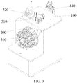
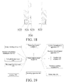
- an existing rotary-disc smoking machine has a rotary disc 81 that horizontally rotates.
- the rotary disc 81 is perpendicular to a horizontal plane with a rotary axis 84 as a central line.
- Several cigarette clamps are evenly arranged on the rotary disc 81 along a periphery of the rotary disc 81.
- a cigarette is inserted into a cigarette clamp 82, and the rotary disc 81 horizontally rotates.
- An axial central line of the cigarette is perpendicular to the rotary axis 84.
- smoke is transmitted to a catcher in the rotary-disc smoking machine from a smoke transmission bending pipe 83 of 90 degrees behind the cigarette clamp 82.
- each smoking hole channel 85 is linearly arranged.
- Each smoking hole channel 85 is provided with a cigarette clamp correspondingly.
- Each smoking hole channel 85 is connected to an independent smoking unit. When several cigarettes are lit together, the cigarettes are synchronously smoked based on a smoking capacity defined by a standard.
- a control circuit is triggered by a switch manually or through pneumatic pressure and supplies power to a heating wire.
- a current enables the heating wire to generate a high temperature.
- a fiberglass oil guiding rope twisting inside the heating wire is affected by the high temperature and generates a wick effect.
- Tobacco tar is continuously transmitted to a high temperature end along the fiberglass oil guiding rope.
- the tobacco tar is instantly heated and vaporized into smoke.
- a smoker smokes by using a cigarette holder. Airflow enters from a vapor inlet hole, and vapor smoke generated in an atomization cavity is inhaled from the cigarette holder to obtain a feeling similar to cigarette smoking.
- the tobacco tar can flow in a storage cavity but is unevenly distributed.
- the electronic cigarette does not move on the existing linear smoking machine, but on the existing rotary-disc smoking machine, the electronic cigarette horizontally rotates.
- the tobacco tar is always deposited at a lower portion of a liquid storage cavity due to the gravity.
- the tobacco tar is consumed in a continuous test process.
- a great change may occur on atomization amount due to insufficient tobacco tar replenishment amount, and a smoke amount is decreased.
- different atomization results may be generated in an actual detection process.
- the tobacco tar replenishment amount and timeliness of replenishment cause a difference due to different detection devices or methods. Finally, a deviation and a larger error of a detection result are caused.
- Both of mechanisms of the two conventional smoking machines are not provided with a manually or linkage controlled pressing part, and do not have a function for testing a manually triggered electronic cigarette.
- the two smoking machines For automatic determination of smoking termination of a conventional cigarette, that is, position determination when the cigarette is completely burned, the two smoking machines use a method in which a cotton thread in close contact with the cigarette is burned away or an infrared sensing identification manner.
- An electronic cigarette has no lighting or extinguishment process, the smoking machine cannot directly judge online whether tobacco tar or a battery quantity of the electronic cigarette runs out, that is, a service life of the electronic cigarette.
- a cigarette cartridge portion of an electronic cigarette has a large tobacco tar storage capacity.
- a total aerosol releasing quantity after atomization far exceeds a catching capability of a single fiberglass Cambridge filter. Therefore, when quality stability performance of the electronic cigarette during continuous use is continuously tested, a filter catcher must be changed after several puffs are smoked.
- multiple catcher weighing actions may be added during catching of a single filter.
- an experiment process needs to be manually interrupted to change a catcher provided with a Cambridge filter. In this way, labor costs are inevitably increased, working efficiency is reduced, and a possibility of a deviation or error of an experiment result is increased to a great extent.
- US3732874A relates to a smoking machine that includes a pair of parallel disks alternately rotatable about a common axis and each provided with a number of holders for cigarettes or other smokable articles. Means is provided for automatically lighting the cigarettes.
- the holders are spaced apart at equal intervals in circular paths respectively centered on the axis of the disks.
- a shuttle valve is mounted at a smoking station between the two disks and adjacent to each to receive a continuous stream of smoke from the cigarettes in sequence and channel it to a desired location, at which there may be, for example, a holder for an experimental animal. The valve shuttles between the two disks to take a puff on each cigarette as it arrives at the smoking station.
- the cigarettes carried on one disk are thus puffed alternately with those carried on the other.
- "Reverse puffing” is employed: i.e., chambers are placed over the lighted ends of the cigarettes and pressurized, so that the smoke is delivered at atmospheric pressure. While a puff is being taken on any given cigarette on one of the disks at the smoking station, the other disk is rotated by an indexer to bring the next cigarette to the smoking station, which is puffed in the same way. The process continues for a number of rotations of the disks, until the cigarettes are smoked to the desired extent, whereupon they are automatically ejected.
- a smoking machine for an electronic cigarette provided in the present invention resolves the following technical problems:
- the present invention provides a smoking machine for an electronic cigarette, comprising: a housing; a rotary disc installed on the housing, the rotary disc rotates relative to the housing with a central axis of the rotary disc as a center; at least one disc-body smoking through hole is provided on an end face of the rotary disc; a housing sealing member is disposed on the housing, a sealing ventilation hole penetrating into an inner portion of the housing is provided in the housing sealing member, and when the sealing ventilation hole is in communication with one end of a catcher, the other end of the catcher is in communication with a smoking apparatus; the central axis of the rotary disc is parallel to a horizontal plane; and at least one cigarette clamping mechanism, comprising a clamping mechanism body and a cigarette clamp disposed on the clamping mechanism body, wherein the cigarette clamp is installed on the disc-body smoking through hole of the rotary disc; one end of the cigarette clamp is a cigarette clamping end for inserting therein an electronic cigarette in a horizontal direction, the
- the central axis of the rotary disc consistent with the present invention is parallel to the horizontal plane, that is, a central line around which the rotary disc rotates is parallel to the horizontal plane.
- the rotary disc is provided with at least one disc-body smoking through hole.
- the disc-body smoking through hole passes through two end faces of the rotary disc.
- the disc-body smoking through hole is provided with the cigarette clamping mechanism for clamping the electronic cigarette.
- the axial through hole of the cigarette clamp on the cigarette clamping mechanism is disposed in the horizontal direction.
- the catcher is pushed to move in the horizontal direction to a smoking position, so that the catcher is in communication with the sealing ventilation hole of the housing sealing member. That is, during smoking, smoke enters the catcher in the horizontal direction from the axial through hole of the cigarette clamp and the sealing ventilation hole of the housing sealing member.
- the catcher and the electronic cigarette can be coaxially arranged, which remarkably reduces bumping condensation deposition of aerosol in a bending pipe of a conventional smoking machine, reduces transmission losses, is beneficial to correctness of smoke detection analysis, and resolves a technical problem that is difficult to solve for a conventional smoking machine during smoking of the electronic cigarette.
- the two or more disc-body smoking through holes are evenly arranged on the rotary disc, and distances between central axes of the disc-body smoking through holes and the central axis of the rotary disc are the same.
- this structure enables the axial through hole of the cigarette clamp to sequentially come into communication with the sealing ventilation hole of the housing sealing member.
- the housing sealing member is disposed on an upper portion of a side surface of the housing, and a central axis of the sealing ventilation hole and the central axis of the rotary disc both pass through a vertical plane perpendicular to the horizontal plane.
- the catcher is generally disposed inside from a top portion of the housing.
- the housing sealing member is disposed on an upper portion of the housing, and the central axis of the sealing ventilation hole and the central axis of the rotary disc pass through the vertical plane. This structure enables the axial through hole to move to a position close to the top portion of the housing and come into communication with the sealing ventilation hole of the housing sealing member.
- an end face of the housing sealing member is in contact with the end face of the rotary disc, and the end face of the rotary disc in contact with the housing sealing member is a plane. This facilitates the end face of the rotary disc and the sealing ventilation hole of the housing sealing member to be sealed during rotation of the rotary disc.
- the smoking machine for an electronic cigarette further comprises an automatic loading and weighing system of a catcher
- the automatic loading and weighing system of a catcher comprises: a temporary feeding storage store and a temporary discharge storage store, which are disposed on the housing of the smoking machine for an electronic cigarette and in communication with an inner portion of the housing; a transmission mechanism, a balance, an ejector pin assembly, and a discharge transferring mechanism, which are disposed inside the housing; and a main control circuit board electrically connected to the ejector pin assembly, the transmission mechanism, the temporary feeding storage store, the temporary discharge storage store, and the discharge transferring mechanism; the temporary feeding storage store receives the catcher disposed from an outer portion of the smoking machine for an electronic cigarette, and the catcher is taken out from the temporary discharge storage store; a robotic arm is installed on the transmission mechanism, the robotic arm obtains the catcher, the transmission mechanism drives the robotic arm to move, so that the catcher reaches a preparation position and a weighing position, and during moving of the catcher,
- the catcher is disposed inside the temporary feeding storage store from the outer portion of the smoking machine for an electronic cigarette.
- the main control circuit board controls the transmission mechanism to drive the robotic arm to move from the preparation position to a supporting position close to the bottom of the temporary feeding storage store.
- the preparation position is an initial zero position.
- the position is a reference position from which the robotic arm moves to other working positions and is used for calculating a moving distance.
- the main control circuit board controls the catcher in the temporary feeding storage store to fall on the robotic arm.
- the robotic arm carries the catcher and returns to the preparation position.
- the main control circuit board controls the ejector pin assembly to push the catcher to the smoking position, so that the catcher comes into connection to a smoking end of the electronic cigarette, and the vapor channel comes into communication with the catcher.
- the smoking apparatus sucks vapor from the electronic cigarette by using the vapor channel, and vapor smoke of the electronic cigarette is absorbed by the catcher.
- the main control circuit board controls the ejector pin assembly to contract.
- the main control circuit board controls the transmission mechanism to drive the catcher on the robotic arm to move to the weighing position of the balance and the balance weighs the catcher.
- the catcher is transmitted to a discharge position of the temporary discharge storage store by a discharge transferring mechanism.
- a ventilation direction of the catcher is always consistent with a smoking experiment direction of the electronic cigarette.
- the catcher drops material and cooperates with the robotic arm depending on the gravity, thereby ensuring that the catcher is quickly and stably changed within a smoking interval of two puffs.
- the catcher is always controlled by the robotic arm inside the smoking machine.
- the smoking position is quite close to the weighing position, so that the robotic arm can quickly move to a required position under control of the main control circuit board. This ensures that the catcher returns to the smoking position after a weighing action is completed within the smoking interval of two puffs.
- the discharge transferring mechanism comprises an inclined slideway for the catcher to slide and a discharge pushing cylinder.
- a horizontal height of an end of the inclined slideway close to the temporary discharge storage store is less than a horizontal height of an end of the inclined slideway far away from the temporary discharge storage store, the discharge pushing cylinder is disposed below the end of the inclined slideway close to the temporary discharge storage store, and a piston rod of the discharge pushing cylinder is located exactly below the temporary discharge storage store.
- the discharge transferring mechanism is provided with the inclined slideway.
- the robotic arm places the catcher at the end of the slideway far away from the temporary discharge storage store, the catcher slides along an inclined direction of the inclined slideway to the end of the inclined slideway close to the temporary discharge storage store.
- the piston rod of the discharge pushing cylinder is exactly below the catcher.
- the main control circuit board controls the piston rod of the discharge pushing cylinder to push the catcher in a vertical direction, so that the catcher can be quickly pushed to the discharge position of the temporary discharge storage store.
- the catcher comprises a catching body and a vapor guiding head disposed on each of two axial end faces of the catching body, the robotic arm is formed by two grippers with a V-shaped groove at an end portion, and the V-shaped groove supports the corresponding vapor guiding head.
- This structure enables the grippers of the robotic arm to stably support the vapor guiding head and facilitates the robotic arm to drive the catcher to move.
- the ejector pin assembly comprises an ejector pin cylinder and an adapter sealing member.
- the adapter sealing member is connected to a piston rod of the ejector pin cylinder, the vapor channel is disposed on the adapter sealing member, and when the catcher is located at the smoking position, the adapter sealing member is in sealing connection to a vapor outlet end of the catcher, and the vapor channel communicates the catcher with the smoking apparatus.
- This structure can quickly push the catcher to the smoking position and enable the catcher to be in sealing connection to the vapor channel.
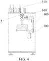
- the smoking machine for an electronic cigarette further comprises an electronic cigarette triggering system
- the electronic cigarette triggering system comprises a cigarette triggering portion and a triggering control cylinder connected to the cigarette triggering portion, the cigarette triggering portion is able to come into contact with the electronic cigarette under control of the triggering control cylinder, the triggering control cylinder is fixed on a connection block, and the connection block is connected to the housing by using a connection structure.
- a dedicated electronic cigarette triggering system is installed on the housing, so that automatic control of electronic cigarette triggering is implemented, and a problem that an existing smoking machine does not have a manually triggered electronic cigarette triggering system and external power supply is resolved.
- the cigarette triggering portion comprises a negative contact terminal and a positive contact terminal
- the negative contact terminal corresponds to a position of a negative electrode of the electronic cigarette
- the positive contact terminal corresponds to a position of a positive electrode of the electronic cigarette
- the negative contact terminal and the positive contact terminal are connected to a current control apparatus.
- a steady direct current supplied by the current control apparatus of the smoking machine is used.
- Power is supplied to the cigarette cartridge connected to the electronic cigarette rod in a manner in which the positive contact terminal and the negative contact terminal are respectively in contact with the positive electrode and negative electrode of the electronic cigarette.
- parameters such as a voltage, a current, and power can be adjusted and set by using the current control apparatus, the temperature of a heating wire can be changed, atomization efficiency of tobacco tar under different electric quantities can be examined, and a technical basis is provided for research and development of a product.
- the cigarette triggering portion comprises a cigarette pressing terminal, and the cigarette pressing terminal corresponds to a position of a power-on button of the electronic cigarette.
- a pre-triggering time may be set pinpointing to a millisecond level, an advance amount of a specified triggering time may be implemented, thereby eliminating a delay problem of the triggering time and more accurately cooperating with a smoking starting time of the smoking machine.
- the clamping mechanism body comprises a horizontal base plate and a vertical supporting plate, an upper surface of the horizontal base plate is provided with a guiding groove, the guiding groove is disposed in a direction of the length of the horizontal base plate; and a bottom portion of the vertical supporting plate is connected to a rear end of the horizontal base plate, and the vertical supporting plate is provided with a base through hole penetrating in a horizontal direction; the other end of the cigarette clamp is a disc body connection end, and the disc body connection end penetrates into the base through hole of the vertical supporting plate; and the cigarette clamping mechanism further comprises a cigarette gripper, and the cigarette gripper comprises a gripper base plate and two side surface clamping portions disposed opposite to each other provided on the gripper base plate, the gripper base plate is installed on the guiding groove of the horizontal base plate and is movable in a direction of the length of the guiding groove, and the two side surface clamping portions are symmetrically disposed by using a vertical plane of a central axis of the
- the smoking end of a cigarette is inserted into the cigarette clamping end of the cigarette clamp. Since the two side surface clamping portions are symmetrically disposed by using a vertical plane of a central axis of the axial through hole as an axial plane, after the two side surface clamping portions disposed opposite to each other clamp side surfaces of the cigarette, a central axis of the cigarette can accurately align with the axial through hole on the cigarette clamp, keeping the cigarette airtight all the time after being inserted into the cigarette clamp and keeping a position of the cigarette to be stable.
- the gripper base plate is movable along the direction of the length of the guiding groove, a position at which the two side surface clamping portions clamp the cigarette can change based on a structure of the cigarette. This enables cigarette clamping mechanism consistent with the present invention to clamp cigarettes of various types.
- the rotary disc consistent with the present invention is perpendicular to the horizontal plane, and the electronic cigarette circumferentially rotates along with the rotary disc in a smoking experiment process, so that tobacco tar in a cigarette cartridge flows and fully immerses the oil guiding cotton, thus ensuring sufficient and steady supply of the tobacco tar to an atomizer, and guaranteeing atomization efficiency, atomization amount, and the stability and accuracy of experiment data.
- the cigarette clamping mechanism cooperates with a rotation direction of the rotary disc to stably clamp the electronic cigarette.
- the automatic loading and weighing system of the catcher cooperates with an operation direction of the rotary disc to control the catcher to move to a required position.
- a ventilation direction of the catcher is always consistent with a smoking experiment direction of the electronic cigarette. This can ensure that the catcher is quickly and stably changed during a smoking interval of two puffs, and can also ensure that the catcher returns to the smoking position after a weighing action is completed during the smoking interval of two puffs.
- the electronic cigarette triggering system consistent with the present invention implements automatic control of triggering of the electronic cigarette and resolves a problem that an existing smoking machine does not have a manually triggered electronic cigarette triggering system and external power supply.
- a smoking machine for an electronic cigarette comprises:
- the central axis of the rotary disc 200 consistent with the present invention is parallel to the horizontal plane, that is, a central line around which the rotary disc 200 rotates is parallel to the horizontal plane.
- the rotary disc 200 is provided with at least one disc-body smoking through hole 210.
- the disc-body smoking through hole 210 passes through two end faces of the rotary disc 200.
- the disc-body smoking through hole 210 is provided with the cigarette clamping mechanism for clamping the electronic cigarette 1.
- the axial through hole 322 of the cigarette clamp 320 on the cigarette clamping mechanism is disposed in the horizontal direction. When the axial through hole 322 of the cigarette clamp 320 rotates to a position aligning with the sealing ventilation hole 121, the axial through hole 322 can come into communication with the sealing ventilation hole 121.
- the catcher 2 is pushed to move in the horizontal direction to a smoking position, so that the catcher 2 is in communication with the sealing ventilation hole 121 of the housing sealing member 120. That is, during smoking, smoke goes into the catcher 2 in the horizontal direction from the axial through hole 322 of the cigarette clamp 320 and the sealing ventilation hole 121 of the housing sealing member 120.
- the catcher 2 and the electronic cigarette 1 can be coaxially arranged, which remarkably reduces bumping condensation deposition of aerosol in a bending pipe of a conventional smoking machine, reduces transmission losses, is beneficial to correctness of smoke detection analysis, and resolves a technical problem that is difficult to solve for a conventional smoking machine during smoking of the electronic cigarette 1.
- a central axis of the disc-body smoking through hole 210 is parallel to the central axis of the rotary disc 200; a central axis of a sealing installment hole 110 passes through a circular rotation track by which a center point of the disc-body smoking through hole 210 passes when the rotary disc 200 rotates; and the sealing ventilation hole 121 penetrates into the housing sealing member 120 in a horizontal direction.
- the smoking machine for an electronic cigarette comprises a main control circuit board 300, the main control circuit board 300 is electrically connected to the rotary disc 200, and the main control circuit board 300 controls the rotary disc 200 to rotate.
- a center of the rotary disc 200 is further provided with a housing connection hole 220.
- the housing connection hole 220 is in nested connection to a base connected to the housing 100.
- the cigarette clamping end 321 of the cigarette clamp 320 is in axial concentric sealing connection to the corresponding disc-body smoking through hole 210 on the rotary disc 200 by using a clamping portion O-shaped spring.
- the housing sealing member 120 comprises a sealing core 122.
- the sealing ventilation hole 121 passes through two end faces of the sealing core 122 in a horizontal direction.
- One end of the sealing core 122 close to the rotary disc 200 is provided with an annular concave groove, and the annular concave groove is located between an outer surface of the sealing core 122 and the sealing ventilation hole 121.
- the annular concave groove is sequentially provided with a ring-shaped spring 123, a sealing portion O-shaped spring 124, an annular wear-resistant member, and a spiral cap 125.
- the end face of the rotary disc 200 remains in great contact with a contact surface of the spiral cap 125, and the end face of the rotary disc 200 can perform sliding friction and is airtight.
- the ring-shaped spring 123 remains elastic and enables the end of the sealing core 122 close to the rotary disc 200 to have a certain scalability performance.
- One end of the sealing core 122 far away from the rotary disc 200 axially forms a conical hole.
- a central portion of a conical torus of the conical hole forms a sealing ring-shaped concave groove.
- the sealing ring-shaped concave groove is provided with an adaptable catching sealing O-shaped spring 126, used to support a vapor inlet of the catcher 2 and keep airtight.
- the two or more disc-body smoking through holes 210 are evenly arranged on the rotary disc 200, and distances between central axes of the disc-body smoking through holes 210 and the central axis of the rotary disc 200 are the same.
- this structure enables the axial through hole 322 of the cigarette clamp 320 to sequentially come into communication with the sealing ventilation hole 121 of the housing sealing member 120.
- the housing sealing member 120 is disposed on an upper portion of a side surface of the housing 100, and a central axis of the sealing ventilation hole 121 and the central axis of the rotary disc 200 both pass through a vertical plane perpendicular to the horizontal plane.
- the catcher 2 is generally disposed inside from a top portion of the housing 100. To facilitate the catcher 2 to quickly move to the smoking position corresponding to the sealing ventilation hole 121 of the housing sealing member 120, the housing sealing member 120 is disposed on an upper portion of the housing 100, and the central axis of the sealing ventilation hole 121 and the central axis of the rotary disc 200 pass through the vertical plane.
- This structure enables the axial through hole 322 to move to a position close to the top portion of the housing 100 and come into communication with the sealing ventilation hole 121 of the housing sealing member 120.
- An end face of the housing sealing member 120 is in close contact with the end face of the rotary disc 200. During rotation of the rotary disc 200, it is ensured that a channel in which smoke flows is isolated from the outside atmosphere and no smoke leakage phenomenon happens.
- the rotary disc 200 is flat cylindrical, so that the two end faces of the rotary disc 200 are parallel and are planes. This facilitates the end face of the rotary disc 200 to be sealed with the sealing ventilation hole 121 of the housing sealing member 120 during rotation of the rotary disc 200.
- the smoking machine for an electronic cigarette further comprises an automatic loading and weighing system of a catcher
- the automatic loading and weighing system of a catcher comprises: a temporary feeding storage store 510 and a temporary discharge storage store 520, which are disposed on the housing 100 of the smoking machine for an electronic cigarette and in communication with an inner portion of the housing 100; a transmission mechanism 600, a balance 700, an ejector pin assembly 400, and a discharge transferring mechanism 800, which are disposed inside the housing 100; and a main control circuit board 300 electrically connected to the ejector pin assembly 400, the transmission mechanism 600, the balance 700, the temporary feeding storage store 510, the temporary discharge storage store 520, and the discharge transferring mechanism 800, the temporary feeding storage store 510 receives the catcher 2 disposed from an outer portion of the smoking machine for an electronic cigarette, and the catcher 2 is taken out from the temporary discharge storage store 520; a robotic arm 610 is installed on the transmission mechanism 600, the robotic arm 610 obtains the catcher 2, and the transmission mechanism 600 drives
- the temporary feeding storage store 510 and the temporary discharge storage store 520 may be disposed on a top surface of the housing 100, and the discharge transferring mechanism 800 transfers the catcher 2 to the discharge position of the temporary discharge storage store 520 in a vertical direction.
- the catcher 2 is disposed in the temporary feeding storage store 510 from the outer portion of the smoking machine for an electronic cigarette.
- the main control circuit board 300 controls the transmission mechanism 600 to drive the robotic arm 610 to move from the preparation position to a supporting position close to the bottom of the temporary feeding storage store 510.
- the preparation position is an initial zero position.
- the position is a reference position from which the robotic arm 610 moves to other working positions and is used for calculating a moving distance.
- the main control circuit board 300 controls the catcher 2 in the temporary feeding storage store 510 to fall on the robotic arm 610.
- the robotic arm 610 carries the catcher 2 and returns to the preparation position.
- the main control circuit board 300 controls the ejector pin assembly 400 to push the catcher 2 to the smoking position, and the robotic arm 610 moves together, so that the catcher 2 comes into connection to a smoking end of the electronic cigarette 1 by using the housing sealing member 120, the vapor channel 421 comes into communication with the catcher 2, the smoking apparatus 440 sucks vapor from the electronic cigarette 1 by using the vapor channel 421, and vapor smoke of the electronic cigarette 1 is absorbed by the catcher 2. Based on a specified condition, after a quantity of puffs or cigarettes is smoked, the main control circuit board 300 controls the ejector pin assembly 400 to contract.
- the main control circuit board 300 controls the transmission mechanism 600 to drive the catcher 2 on the robotic arm 610 to spring to the preparation position, and then the catcher 2 moves downward to the weighing position of the balance 700.
- the robotic arm continues to move downward and is slightly separated from the catcher 2, and the balance weighs the catcher 2.
- the main control circuit board 300 controls the transmission mechanism 600 to drive the robotic arm 610 to rise and return to the preparation position.
- the main control circuit board 300 controls the ejector pin assembly 400 to eject the catcher 2 to the smoking position again to perform smoking.
- the smoking and weighing process is repeated based on a specified smoking condition.
- the catcher 2 needs to be taken out when a smoking termination condition is reached, the catcher 2 is transmitted by the discharge transferring mechanism 800 to the discharge position of the temporary discharge storage store 520 by a discharge transferring mechanism.
- a direction at which the central axis of the sealing ventilation hole 121 is located is a smoking experiment direction of the electronic cigarette 1
- the catcher 2 falls on the robotic arm 610 located at a supporting position in a vertical direction, and in a process when the robotic arm 610 drives the catcher 2 to move to the preparation position, the weighing position, and the discharge position, the central axis of the catcher 2 remains in parallel to the central axis of the sealing ventilation hole 121. In this way, when the system consistent with the present invention is used, a ventilation direction of the catcher 2 is always consistent with the smoking experiment direction of the electronic cigarette 1.
- the catcher 2 drops material and cooperates with the robotic arm 610 depending on the gravity, thereby ensuring that the catcher 2 is quickly and stably changed within a smoking interval of two puffs. That is, the electronic cigarette 1 changes the catcher 2 within 27s of the smoking interval of two puffs.
- the catcher 2 is always in an effective control range of the robotic arm 610 inside the smoking machine. Both of the transmission mechanism 600 and the balance 700 are located inside the housing 100. The weighing position and the smoking position are quite close. After smoking is completed, the robotic arm 610 can conveniently move the catcher 2 to the weighing position. After weighing is completed, the robotic arm 610 can move the catcher 2 to the smoking position again. An entire process in which the catcher 2 is moved to the weighing position to be weighed and then returns to the smoking position is controlled by the main control circuit board 300. Therefore, it may also be ensured that all actions are completed within a smoking interval of two puffs. That is, after transferring the catcher 2 from the smoking position to the weighing position to perform weighing within 27s of the smoking interval of two puffs, then returning the catcher 2 to the smoking position.
- the present invention provides an optimized cooperation relationship between rotation of the rotary disc 200 and the automatic loading and weighing system of the catcher 2. While conforming to a related standard rule of a single smoking duration and a smoking volume of the electronic cigarette 1, at least two test procedures may be implemented as follows. Procedure 1: When multiple electronic cigarettes 1 with a same brand and specification are loaded on the rotary disc 200, each of the multiple electronic cigarettes 1 may be continuously and sequentially smoked for one or more puffs. Released aerosol is caught by a filter of the catcher 2. In this process, a smoking interval of two puffs of a single electronic cigarette 1 needs to be longer than 27s according to a rule.
- a smoking process in which the electronic cigarettes 1 are sequentially smoked is set, that is, a next electronic cigarette is smoked after a single electronic cigarette 1 is completely smoked.
- the catcher 2 is automatically changed based on a quantity of puffs of smoking or a set value of a minimum catching amount.
- a continuous test process may complete each puff analysis, entire smoke analysis, and service life detection of multiple electronic cigarettes 1 with different brands and specifications.
- the discharge transferring mechanism 800 comprises an inclined slideway 810 for the catcher 2 to slide and a discharge pushing cylinder 820, a horizontal height of an end of the inclined slideway 810 close to the temporary discharge storage store 520 is less than a horizontal height of an end of the inclined slideway 810 far away from the temporary discharge storage store 520, the discharge pushing cylinder 820 is disposed below the end of the inclined slideway 810 close to the temporary discharge storage store 520, a piston rod of the discharge pushing cylinder 820 is located exactly below the temporary discharge storage store 520, and the piston rod of the discharge pushing cylinder 820 is provided with a supporting portion supporting the catcher 2.
- the inclined slideway 810 is disposed to quickly transfer the catcher 2 to the discharge position. After the robotic arm 610 places the catcher 2 at the end of the slideway 810 far away from the temporary discharge storage store 520, the catcher 2 slides along an inclined direction of the inclined slideway 810 to the end of the inclined slideway 810 close to the temporary discharge storage store 520. In this case, the piston rod of the discharge pushing cylinder 820 is exactly below the catcher 2.
- the main control circuit board 300 controls the piston rod of the discharge pushing cylinder 820 to push the catcher 2 in the vertical direction, so that the catcher 2 can be quickly pushed to the discharge position of the temporary discharge storage store 520.
- the temporary feeding storage store 510 is provided with a feeding guiding groove 511 to insert the catcher 2.
- a rotary stopper 512 that can rotate to release the catcher 2 and a feeding identification apparatus 513 that identifies a position of the catcher 2 are disposed in the feeding guiding groove 511. Both the rotary stopper 512 and the feeding identification apparatus 513 are electrically connected to the main control circuit board 300.
- the rotary stopper 512 comprises a stopping portion 514 that can support the catcher 2 and prevent the catcher 2 from moving downward.
- the stopping portion 514 also rotates for 180 degrees, so that the catcher 2 is not restricted by the stopping portion 514 and falls into an inner portion of the housing 100.
- the feeding identification apparatus 513 transmits information of the catcher 2 in the feeding guiding groove 511 to the main control circuit board 300.
- the main control circuit board 300 controls the rotary stopper 512 to rotate by 180 degrees to release the catcher 2, so that the catcher 2 falls on the robotic arm 610 located at the supporting position inside the housing 100.
- the feeding guiding groove 511 limits the position of the catcher 2. Therefore, in the process that the catcher 2 enters the preparation position from the feeding guiding groove 511, the central axis of the catcher 2 is always parallel to a horizontal plane.
- the temporary discharge storage store 520 is provided with a discharge guiding groove 521 to insert the catcher 2.
- An ejecting and pushing stopper 522 that can be turned on when the catcher 2 pushes upward and a discharge identification apparatus 523 that identifies the position of the catcher 2 are disposed in the discharge guiding groove 521. Both the ejecting and pushing stopper 522 and the discharge identification apparatus 523 are electrically connected to the main control circuit board 300.
- the ejecting and pushing stopper 522 comprises two limiting members 524 disposed opposite to each other in the discharge guiding groove 521. Both of the two limiting members 524 are movably connected to the discharge guiding groove 521. The length of an upper portion of the limiting member 524 in a horizontal direction is greater than the length of a lower portion of the limiting member 524 in a horizontal direction.
- the catcher 2 is pushed by the piston rod of the discharge pushing cylinder 820 to the temporary discharge storage store 520.
- the catcher 2 may push the two limiting members 524 to rotate, so that the catcher 2 passes the two limiting members 524.
- the main control circuit board 300 controls the two limiting members 524 to return to an original position and support the catcher 2.
- the piston rod of the discharge pushing cylinder 820 may quickly push the catcher 2 in a vertical direction to pass the two limiting members 524 to reach the discharge position of the discharge guiding groove 521.
- the catcher 2 comprises a catching body 21 and a vapor guiding head 22 disposed on each of two axial end faces of the catching body 21; the robotic arm 610 is formed by two gripers 611 with a V-shaped groove at an end portion; and the V-shaped groove supports the corresponding vapor guiding head 22.
- This structure enables the grippers 611 of the robotic arm 610 to stably support the vapor guiding head 22 and facilitate the robotic arm 610 to drive the catcher 2 to move.
- a weighing end of the balance 700 is provided with an adapter 710 corresponding to the catcher 2.
- the shape of a supporting surface 711 of the adapter 710 corresponds to the shape of a side surface of the catching body 21.
- the supporting surface 711 is arc-shaped. This structure enables the side surface of the catching body 21 of the catcher 2 to be stably placed on the adapter 710, thereby facilitating weighing of the catcher 2.
- the balance 700 is located below the preparation position, so that the robotic arm 610 quickly moves from the smoking position to the weighing position by passing the preparation position.
- the ejector pin assembly 400 comprises an ejector pin cylinder 410 and an adapter sealing member 420.
- the adapter sealing member 420 is connected to a piston rod 41 of the ejector pin cylinder 410, and the vapor channel 421 is disposed on the adapter sealing member 420.
- the adapter sealing member 420 is in sealing connection to a vapor outlet end of the catcher 2, and the vapor channel 421 communicates the catcher 2 with the smoking apparatus 440.
- This structure can quickly push the catcher 2 to the smoking position and enable the catcher 2 to be in sealing connection to the vapor channel 421.
- the adapter sealing member 420 is connected to the smoking apparatus 440 by using a vapor guiding connection rod 430, and the vapor guiding connection rod 430 is in communication with the vapor channel 421.
- the smoking apparatus 440 is in communication with the vapor channel 421 on the adapter sealing member 420 by using the vapor guiding connection rod 430. After smoking is performed, vapor smoke of the electronic cigarette 1 is absorbed by the catcher 2. Both of the smoking apparatus 440 and the ejector pin cylinder 410 are electrically connected to the main control circuit board 300.
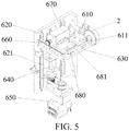
- the transmission mechanism 600 comprises: a vertical guiding plate 620, the vertical guiding plate 620 is provided with a vertical guiding rail 621; a horizontal supporting plate 630, which is installed on the vertical guiding rail 621, and the horizontal supporting plate 630 can vertically move along the vertical guiding rail 621, the horizontal supporting plate 630 is connected to a vertical driving shaft 640, and the vertical driving shaft 640 is connected to a vertical driving motor 650; a horizontal guiding rod 660, which is disposed on the horizontal supporting plate 630; a horizontal guiding plate 680, which is movably connected to the horizontal supporting plate 630, and the horizontal guiding plate 680 can horizontally move on the horizontal supporting plate 630; a horizontal driving motor 670, which is connected to the horizontal guiding plate 680, an output axis of the horizontal driving motor 670 is movable along the horizontal guiding rod 660 in a horizontal direction; and a horizontal guiding rail 681, which is disposed on the horizontal guiding rail 681, which is disposed on the horizontal
- the robotic arm 610 is movably connected to the horizontal guiding rail 681 by using a spring, and the robotic arm 610 is movable along the horizontal guiding rail 681. Both of the vertical driving motor 650 and the horizontal driving motor 670 are electrically connected to the main control circuit board 300.
- the vertical driving motor 650 drives the horizontal supporting plate 630 to move in a vertical direction by using the vertical driving shaft 640.
- the horizontal driving motor 670 drives the horizontal guiding plate 680 to move along the horizontal guiding rod 660.
- the robotic arm 610 can drive the catcher 2 to move along the horizontal guiding rail 681. Since the direction at which the central axis of the horizontal guiding rail 681 is located is perpendicular to the direction in which the horizontal guiding plate 680 horizontally moves on the horizontal supporting plate 630, therefore, the transmission mechanism 600 can enable the robotic arm 610 to drive the catcher 2 to quickly move in three directions perpendicular to each other. In this way, the catcher 2 can quickly move to a required position.
- a usage method of the automatic changing and weighing system of a catcher according to the present embodiment comprises the following steps.
- the catcher 2 is disposed at a feeding position in the temporary feeding storage store 510 from an outer portion of the smoking machine for an electronic cigarette.
- the main control circuit board 300 controls the transmission mechanism 600 to drive the robotic arm 610 to move to the supporting position close to the bottom portion of the temporary feeding storage store 510.
- the main control circuit board 300 controls the rotary stopper 512 of the temporary feeding storage store 510 to rotate by 180 degrees.
- the main control circuit board 300 controls the robotic arm 610 to carry the catcher 2 and move to the preparation position.
- the main control circuit board 300 controls the ejector pin assembly 400 to push the catcher 2 to the smoking position in a horizontal direction.
- the robotic arm 610 moves with the catcher 2, and a spring (not shown in the figures) of the robotic arm 610 connected to the horizontal guiding rail 681 contracts.
- the catcher 2 is connected to the smoking end of the electronic cigarette 1.
- the vapor channel 421 of the ejector pin assembly 400 is in communication with the catcher 2.
- the main control circuit board 300 controls the smoking apparatus 440 to smoke the electronic cigarette 1 by using the vapor channel 421, so that vapor smoke of the electronic cigarette 1 enters the catcher 2 and is absorbed by the catcher 2.
- the main control circuit board 300 controls the ejector pin assembly 400 to contract.
- the spring of the robotic arm 610 connected to the horizontal guiding rail 681 extends, and the robotic arm 610 drives the catcher 2 to return to the preparation position.
- the main control circuit board 300 controls the transmission mechanism 600, so that the transmission mechanism 600 drives the catcher 2 on the robotic arm 610 to move to the weighing position of the balance 700.
- the main control circuit board 300 controls the robotic arm 610 to release the catcher 2, and the balance 700 measures the weight of the catcher 2.
- the main control circuit board 300 controls the robotic arm 610 by using the transmission mechanism 600, so that the catcher 2 moves to an end of the inclined slideway 810 far away from the temporary discharge storage store 520.
- the robotic arm 610 releases the catcher 2, and the catcher 2 slides along the inclined slideway 810 to the supporting portion of the discharge pushing cylinder 820.
- the main control circuit board 300 controls the piston rod of the discharge pushing cylinder 820 to move upward to drive the catcher 2 to push the ejecting and pushing stopper 522 in the temporary discharge storage store 520 to open.
- the discharge identification apparatus 523 transmits detected information indicating that the catcher 2 is located at the discharge position to the main control circuit board 300.
- the main control circuit board 300 controls the two limiting members 524 to return to an initial position and support the catcher 2 below the catcher 2.
- a quantity of smoking puffs of the electronic cigarette 1 is far greater than that of a conventional cigarette, and generally comprises at least 150 or more than 150 puffs.
- a fiberglass Cambridge filter having a diameter of 44 mm well known in this professional technical field is generally used for catching smoke, and a theoretical smoke carrying amount of the fiberglass Cambridge filter is 150 mg.
- a catcher 2 provided with a Cambridge filter needs to be changed after a quantity of smoking puffs. Therefore, the temporary feeding storage store 510 and the temporary discharge storage store 520 of the catcher 2 designed by the present invention are vertically arranged on the top portion of the housing 100.
- An axial direction of the catcher 2 is consistent with a direction of the catcher 2 in a smoking experiment.
- a direction of the vapor inlet of the catcher 2 keeps facing the rotary disc 200.
- the catcher drops material and cooperates with the robotic arm 610 depending on the gravity, thereby ensuring that the catcher 2 is quickly and stably changed within a smoking interval of two puffs.
- the catcher 2 In the continuous measurement process, when a quality change of the catcher 2 in the smoking process needs to be monitored before the catcher 2 is changed, that is, when an amount change occurs on smoke of the electronic cigarette 1, the catcher 2 needs to be weighed at an interval of a quantity of smoking puffs (for example, 1, 2, 3, ... puffs). In this case, the catcher 2 must be removed from a smoking working position originally sealed between the smoking hole channel and a smoking unit of the electronic cigarette 1 and be loaded at the original smoking working position and sealed again after being weighed.
- a quality change of the catcher 2 in the smoking process needs to be monitored before the catcher 2 is changed, that is, when an amount change occurs on smoke of the electronic cigarette 1
- the catcher 2 needs to be weighed at an interval of a quantity of smoking puffs (for example, 1, 2, 3, ... puffs).
- the catcher 2 must be removed from a smoking working position originally sealed between the smoking hole channel and a smoking unit of the electronic cigarette 1 and be loaded at the original smoking working
- a maximum interval of two smoking puffs does not exceed 1 min.
- an interval between two smoking puffs of the electronic cigarette 1 is generally stipulated as 27s.
- the balance 700 disposed inside the smoking machine and the adapter 710 of the balance 700 used to support the catcher 2 are disposed below and quite close to the smoking working position.
- the catcher 2 is pushed to the smoking working position by the ejector pin assembly 400 located at a direction of a vapor outlet of the catcher 2.
- the ejector pin cylinder 410 releases an ejector pin.
- the catcher 2 is supported by the robotic arm 610 and is quickly sent to the adapter 710 supported by the balance 700.
- the catcher 2 is returned by the robotic arm 610, and the ejector pin assembly 400 is tightly pushed again.
- a data collection process of transferring and weighing of the catcher 2 is fully and automatically completed by an instrument, thereby ensuring that all actions are completed within the smoking interval of two puffs.
- a method for determining smoking determination by using a weighting method may be implemented, so as to resolve a determining problem of smoking determination of the electronic cigarette 1:
- a conventional cigarette generates smoke by burning a tobacco segment of the cigarette. Therefore, when the cigarette is burned to a cigarette stub length defined by a standard, a cotton thread in close contact with an outer surface of the cigarette and located at a termination position is burned away to trigger a micro switch, or an infrared sensor disposed at a corresponding position is triggered to terminate smoking.
- the largest value in the following three sets of data is used as the cigarette stub length determining smoking termination: 1. a cigarette without a cigarette filter is 23 mm away from the smoking end; 2.
- the length of a cigarette filter rod is +8 mm; 3. the length of tipping paper is +3 mm.
- the electronic cigarette 1 atomizes tar in the electronic cigarette 1 to generate smoke without a lighting and burning process.
- the method and an apparatus for determining smoking termination of a conventional smoking machine cannot determine whether the electronic cigarette 1 completes smoking.
- a current conventional smoking machine cannot automatically resolve this technical problem.
- the balance 700 weighs the catcher 2 in combination with actions of the robotic arm 610. A weight change of the catcher 2 obtained by the balance 700 is transferred to the main control circuit board 300. In this method, whether smoke is still generated is determined by examining whether the weight increases. This can indirectly determine whether the tobacco tar or electric quantity runs out, thereby determining that smoking of the electronic cigarette 1 terminates.
- a function may further be expanded as follows: the second puffs, the third puffs, or the like of all the electronic cigarettes 1 are sequentially caught on the first filter, the second filter, or the like.
- An advantage of this manner lies in that, for electronic cigarette 1 products with a same brand or specification, when quality detection needs to be performed on an entire batch of the products, quality levels vary between different individuals of a sample test batch. To reduce a detection data error caused by a produce quality difference, a quantity of tested samples must be increased. If the samples are measured one by one by using the conventional smoking machine, that is, the second cigarette is smoked after the first cigarette is completely smoked, a smoking interval of two puffs of each cigarette causes a great amount of time waste.
- the system provided by the present invention can fully utilize a smoking interval of each electronic cigarette 1 to complete smoking of other electronic cigarettes 1, thereby greatly improving the smoking detection efficiency.
- a single electronic cigarette 1 is smoked for one puff every 30 seconds, and 10 minutes are consumed to complete 20 puffs of smoking.
- a total time of 100 minutes is consumed to complete smoking 10 cigarettes one by one.
- each puff of smoking a single electronic cigarette 1 lasts for 3 seconds, and the rotary disc 200 rotates for 1 second.
- a next electronic cigarette 1 is smoked for 3 seconds, and the rotary disc 200 rotates for 1 second again.
- a total time consumed to complete a task for all the 200 puffs of smoking all the 10 cigarettes is 13 minutes and 20 seconds, and a time of 86 minutes and 40 seconds is saved.
- the smoking machine for an electronic cigarette is combined with an automatic material changing system of a catcher.
- a function for which the catcher 2 is successively replenished to the smoking machine for an electronic cigarette and the catcher 2 on the smoking machine for an electronic cigarette that has completed a test is taken out and placed in a discharge store of the automatic material changing system of a catcher can be automatically implemented.
- one or more smoking machines controlled by a bus are combined with the automatic material changing system of a catcher.
- the automatic material changing system of a catcher sends an identification instruction to the feeding identification apparatus 513 on the temporary feeding storage store 510 of each smoking machine for an electronic cigarette and receives a feedback signal indicating whether a catcher 2 exists. If no catcher 2 exists, the catcher 2 is delivered from a feeding rack of the automatic material changing system of a catcher to the temporary feeding storage store of each smoking machine for an electronic cigarette.
- the discharge identification apparatus 523 of the temporary discharge storage store 520 sends the feedback signal to the automatic material changing system of a catcher.
- the system takes out the catcher 2 and sends it to a discharge rack of the system.
- the smoking machine for an electronic cigarette further comprises an electronic cigarette triggering system.
- the electronic cigarette triggering system comprises a cigarette triggering portion 3 and a triggering control cylinder 4 connected to the cigarette triggering portion 3.
- the cigarette triggering portion 3 is able to come into contact with the electronic cigarette 1 under control of the triggering control cylinder 4, the triggering control cylinder 4 is fixed on a connection block 5, and the connection block 5 is connected to the housing 100 by using a connection structure 6.
- the electronic cigarette triggering system controls the cigarette triggering portion 3 to perform an action by using the triggering control cylinder 4.
- the cigarette triggering portion 3 comes into contact with the electronic cigarette 1; and when the electronic cigarette 1 needs to be powered off, the cigarette triggering portion 3 hangs close to the electronic cigarette 1 and is not in contact with the electronic cigarette 1.
- the electronic cigarette 1 can be clamped by using the cigarette clamp 320 of the cigarette clamping mechanism and a cigarette gripper 330.
- a rear portion of the electronic cigarette 1 is inserted into the housing 100 and is in communication with the smoking apparatus 440 by using a smoking channel.
- the triggering system is installed at a position exactly above the cigarette clamping mechanism. The triggering system controls power on and off of the electronic cigarette 1, and cooperates with a smoking action of the smoking apparatus 440, thereby implementing a function of stimulating cigarette smoking of a consumer.
- the electronic cigarette 1 generally consists of a cigarette cartridge 201 storing tobacco tar and a cigarette rod for installing the cigarette cartridge 201, wherein the cigarette rod is provided with a battery.
- the battery supplies a current to a thermal resistor 2014 in the cigarette cartridge 201, and the thermal resistor 2014 is heated to atomize the tobacco tar.
- the smoking machine is used to detect the electronic cigarette 1, there are two manners to power on the electronic cigarette 1.
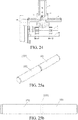
- One manner is to remove an original cigarette rod with the battery of the electronic cigarette 1 and connect the cigarette cartridge 201 to a specially-made electronic cigarette rod 1001 (as shown in Fig. 25a to Fig.
- Another manner is to perform no transformation on the original electronic cigarette 1, but to directly press a power-on button 33 on the cigarette rod of the electronic cigarette 1 in a mechanical manner, thereby powering on the electronic cigarette 1, as shown in Fig. 23 to Fig. 24 .
- the cigarette triggering portion 3 comprises a negative contact terminal 31 and a positive contact terminal 32.
- the negative contact terminal 31 corresponds to a position of the negative electrode 11 of the electronic cigarette 1
- the positive contact terminal 32 corresponds to a position of the positive electrode 12 of the electronic cigarette 1
- the negative contact terminal 31 and the positive contact terminal 32 are connected to a current control apparatus.
- the negative contact terminal 31 and the positive contact terminal 32 are respectively in contact with the negative electrode 11 and the positive electrode 12 under control of the triggering control cylinder 4, thereby powering on the electronic cigarette 1.
- the current control apparatus can adjust parameters such as a current, a voltage, and power, and change the temperature of the thermal resistor 2014 in the cigarette cartridge 201, thereby adjusting an atomization degree of tobacco tar.
- an external direct current has characteristics such as supplying power by using a regulated voltage and a regulated current.
- a one-time charging electric quantity of a rechargeable battery of the electronic cigarette is usually insufficient to completely consume tobacco tar in the cigarette cartridge 201.
- the examination cannot be completed in one time by using the rechargeable battery.
- a sample needs to be removed to recharge the battery, which will inevitably cause an experimental process to be interrupted, resulting in an experimental error.
- a steady direct current supplied by the current control apparatus of the smoking machine is used.
- Power is supplied to the cigarette cartridge 201 in a manner in which the negative contact terminal 31 and the positive contact terminal 32 are respectively in contact with the negative electrode 11 and the positive electrode 12 of the electronic cigarette 1.
- a measurement process is continuous and stable, and measurement data is accurate and effective.
- parameters such as a voltage, a current, and power can be adjusted and set by using the current control apparatus, the temperature of a heating wire can be changed, atomization efficiency of tobacco tar under different electric quantities can be examined, and a technical basis is provided for research and development of a product.
- the present invention specially designs an electronic cigarette rod 1001 applicable to the electronic cigarette triggering system.
- an electronic cigarette 1 formed by the electronic cigarette rod 1001 provided with the cigarette cartridge 201 is applicable to the direct-current power-on mode of the electronic cigarette triggering system.
- a structure of the electronic cigarette rod 1001 is shown in Fig. 25a to Fig. 25c .
- the electronic cigarette rod 1001 comprises a positive electrode pipe 101 and a negative electrode pipe 102 sleeved over the positive electrode pipe 101.
- An end of the positive electrode pipe 101 far away from the cigarette cartridge 201 is in contact with the positive contact terminal 32, and an end of the positive electrode pipe 101 close to the cigarette cartridge 201 passes through the inner portion of the negative electrode pipe 102 and is in contact with a positive electrode of the cigarette cartridge 201.
- An outer surface of the negative electrode pipe 102 is in contact with the negative contact terminal 31, and an end of the negative electrode pipe 102 close to the cigarette cartridge 201 is in contact with a negative electrode of the cigarette cartridge 201.
- the negative electrode pipe 102 is isolated from the positive electrode pipe 101 by using multiple insulation rings.
- the negative electrode pipe 102 and the positive electrode pipe 101 are respectively connected to the negative electrode and the positive electrode of the cigarette cartridge 201, and are further connected to the negative contact terminal 31 and the positive contact terminal 32.
- the negative contact terminal 31 and the positive contact terminal 32 are respectively conductive to the negative electrode and the positive electrode of the cigarette cartridge 201.
- a current from the electronic cigarette triggering system causes the thermal resistor 2014 of the cigarette cartridge 201 to be heated, so that tobacco tar is atomized.
- a function of stimulating cigarette smoking of a consumer is implemented.
- the electronic cigarette rod 1001 may be in threaded connection to the cigarette cartridge 201 or an adapter 105.
- a specific structure is that a conductive threaded head 103 is fixed in the end of the negative electrode pipe 102 close to the cigarette cartridge 201, an outer surface of the threaded head 103 cooperates with an inner surface of the negative electrode pipe 102, and an inner surface of the threaded head 103 is provided with a connection thread.
- the cigarette cartridge 201 or the adapter 105 is provided with a thread corresponding to the thread of the inner surface of the threaded head 103, and the cigarette cartridge 201 or the adapter 105 is in threaded connection to the threaded head 103.
- the inner surface of the threaded head 103 is further provided with a limiting protruding ring 1031 extending radially inward.
- a first insulation ring 104 is filled between the limiting protruding ring 1031 and an outer surface of the positive electrode pipe 101.
- the positive electrode pipe 101 is fixed at a central position of the negative electrode pipe 102 by using the limiting protruding ring 1031 and the first insulation ring 104.
- the limiting protruding ring 1031 and the first insulation ring 104 ensure insulativity between the positive electrode pipe 101 and the negative electrode pipe 102.
- a second insulation ring 106 is further disposed between an end of the negative electrode pipe 102 far away from the cigarette cartridge 201 and the positive electrode pipe 101.
- the second insulation ring 106 also ensures insulativity between the positive electrode pipe 101 and the negative electrode pipe 102.
- the positive electrode pipe 101 comprises a positive electrode pipe rear segment 1011 and a positive electrode pipe front segment 1012.
- the positive electrode pipe front segment 1012 is inserted into the positive electrode pipe rear segment 1011.
- An outer surface of the positive electrode pipe rear segment 1011 is in contact with the positive contact terminal 32, and the positive electrode pipe front segment 1012 is in contact with the positive electrode of the cigarette cartridge 201.
- the middle of the positive electrode pipe 101 is provided with a smoking channel 97 in communication with a smoking channel 111 of the cigarette cartridge 201.
- two ends of the smoking channel 97 of the positive electrode pipe 101 are respectively in communication with the smoking channel 111 of the cigarette cartridge 1 in external air, and the smoking channel 111 of the cigarette cartridge 1 is in communication with the smoking apparatus 440 located inside the smoking machine.
- the electronic cigarette rod 1001 may be directly connected to the cigarette cartridge 1 (as shown in Fig. 26a to Fig. 26c ), or may be connected to the cigarette cartridge 1 by using the adapter 105 (as shown in Fig. 27a to Fig. 27c ).
- the electronic cigarette rod 1001 is directly in threaded connection to the cigarette cartridge 1.
- the cigarette cartridge 201 comprises an atomization cavity 2011 formed by an electronic cigarette pipe 2012 and an electronic cigarette cap 2013.
- the thermal resistor 2014 is disposed inside the atomization cavity 2011.
- the thermal resistor 2014 is connected to a negative conductive pipe 2018 by using a negative wiring 2016, and the thermal resistor 2014 is further connected to a positive conductive pipe 2017 by using a positive wiring 2015.
- the positive conductive pipe 2017 is located inside the negative conductive pipe 2018.
- the negative conductive pipe 2018 is in threaded connection to the threaded head 103 of the electronic cigarette rod 1001.
- the positive conductive pipe 2017 is in contact with the positive electrode pipe 101 of the electronic cigarette rod 1001.
- the negative conductive pipe 2018 is provided with a positioning protruding ring 2019 radially protruding inward.
- a third insulation ring 2020 is disposed between the positioning protruding ring 2019 and the positive conductive pipe 2017.
- the two ends of the smoking channel 97 of the positive electrode pipe 101 are respectively in communication with the smoking channel 111 of the cigarette cartridge 1 in external air, and the smoking channel 111 of the cigarette cartridge 1 extends into the atomization cavity 2011 of the cigarette cartridge 1.
- the atomization cavity 2011 is in communication with the smoking apparatus 440 located inside the smoking machine by using a through hole on the electronic cigarette cap 2013.
- the electronic cigarette rod 1001 is connected to the cigarette cartridge 201 by using the adapter 105.
- the electronic cigarette rod 1001 further comprises the adapter 105.
- the adapter 105 comprises a negative connection pipe 1051 and a positive connection pipe 1052 located inside the negative connection pipe 1051. Two ends of the negative connection pipe 1051 are respectively in contact with the negative electrode pipe 102 and the negative electrode of the cigarette cartridge 201. Two ends of the positive connection pipe 1052 are respectively in contact with the positive electrode pipe 101 and the positive electrode of the cigarette cartridge 201.
- a fourth insulation ring 953 is disposed between the negative connection pipe 1051 and the positive connection pipe 1052.
- the middle of the adapter 105 is further provided with a smoking channel 954 passing through the positive connection pipe 1052.
- the smoking channel 97 of the electronic cigarette rod 1001 is in communication with the smoking channel 111 of the cigarette cartridge 201 by using the smoking channel 954.
- a peripheral surface of the negative connection pipe 1051 is provided with a thread.
- One end of the negative connection pipe 1051 is in threaded connection to the threaded head 103 of the electronic cigarette rod 1001, and the other end is in threaded connection to the cigarette cartridge 201.
- the diameter of the peripheral surface of the negative connection pipe 1051 cooperating with the threaded head 103 and the cigarette cartridge 201 depends on the diameter of a threaded cooperating surface of the threaded head 103 and the cigarette cartridge 201.
- the cigarette cartridges 201 with different diameters may be connected to the electronic cigarette rod 1001 by using the adapter 105, thereby expanding an applicable range of the electronic cigarette rod 1001.
- the cigarette triggering portion 3 comprises a cigarette pressing terminal 13, and the cigarette pressing terminal 13 corresponds to a position of the power-on button 33 of the electronic cigarette 1.
- the triggering control cylinder 4 controls the cigarette pressing terminal 13 to press the power-on button 33 of the electronic cigarette 1, thereby powering on the electronic cigarette 1.
- a pressing force of the cigarette pressing terminal 13 may be adjusted.
- a reducing valve is disposed on the triggering control cylinder 4. Air source pressure of the triggering control cylinder 4 is adjustable by adjusting the reducing valve, thereby controlling the pressure of the cigarette pressing terminal 13, and the cigarette pressing terminal 13 is able to be adaptive to pressing strength required by electronic cigarettes 1 with different versions.
- a pre-triggering time may be set pinpointing to a millisecond level.
- time needs to be controlled quite accurately.
- a pressing action and an electronic cigarette triggering moment itself will lead to a triggering delay.
- an advance amount of a given triggering time may be implemented, thereby eliminating a delay problem of the triggering time.
- the foregoing cigarette triggering portion 3 is fixed on an integrated block 7.
- the integrated block 7 is fixedly connected to the piston rod 41 of the triggering control cylinder 4.
- the integrated block 7 and the cigarette triggering portion 3 are driven to move by triggering scalability of the piston rod 41 of the triggering control cylinder 4, so that a position of the cigarette triggering portion 3 is adjusted and contact between the cigarette triggering portion 3 and the electronic cigarette 1 is controlled.
- an axis of the piston rod 41 of the triggering control cylinder 4 is preferably disposed perpendicular to an axis of the electronic cigarette 1.
- the negative contact terminal 31 and the positive contact terminal 32 of the cigarette triggering portion 3 used for direct current power-on and the cigarette pressing terminal 13 used for pressing power-on may be jointly integrated and installed on one integrated block 7.
- the cigarette triggering portion 3 has two triggering manners and the cigarette triggering portion 3 may flexibly select direct current power-on or pressing power-on.
- a preferable arranging manner is as follows: the cigarette pressing terminal 13 is located between the negative contact terminal 31 and the positive contact terminal 32, and the three terminals are sequentially arranged in a direction parallel to the axis of the electronic cigarette 1.
- the connection structure 6 comprises a fixed rod 61 connected to the smoking machine.
- the fixed rod 61 is provided with a guiding rail 62, and a connection block 5 slides on the guiding rail 62.
- a position of the cigarette triggering portion 3 may be flexibly adjusted when the connection block 5 slides on the guiding rail 62, so that the cigarette triggering portion 3 may be applicable to electronic cigarettes 1 with different specifications.
- an axis of the guiding rail 62 is parallel to the axis of the electronic cigarette 1.
- the connection block 5 is further provided with a lock bolt. After the connection block 5 slides in position, the lock bolt is pressed on the guiding rail 62, so that the connection block 5 is fixed relative to the guiding rail 62.
- a position of the cigarette triggering portion 3 in a direction parallel to the axis of the electronic cigarette 1 is adjusted through the sliding of the connection block 5 on the guiding rail 62; and a position of the cigarette triggering portion 3 in a direction perpendicular to the axis of the electronic cigarette 1 is adjusted through stretching of the piston rod 41 of the triggering control cylinder 4.
- the cigarette triggering portion 3 may be adjusted to different positions.
- the triggering system can be applicable to electronic cigarettes 1 with different specifications.
- the clamping mechanism body 310 comprises a horizontal base plate 311 and a vertical supporting plate 314, an upper surface of the horizontal base plate 311 is provided with a guiding groove 312, the guiding groove 312 is disposed in a direction of the length of the horizontal base plate 311; and a bottom portion of the vertical supporting plate 314 is connected to a rear end of the horizontal base plate 311, and the vertical supporting plate 314 is provided with a base through hole 315 penetrating in a horizontal direction; the other end of the cigarette clamp 320 is a disc body connection end 324, and the disc body connection end 324 passes through the base through hole 315 of the vertical supporting plate 314; and the cigarette clamping mechanism further comprises a cigarette gripper 330, and the cigarette gripper 330 comprises a gripper base plate 331 and two side surface clamping portions 334 disposed opposite to each other provided on the gripper base plate 331, the gripper base plate 331 is installed on the guiding groove 312 of the
- the smoking end of a cigarette is inserted into the cigarette clamping end 321 of the cigarette clamp 320.
- the two side surface clamping portions 334 are symmetrically disposed by using a vertical plane of a central axis of the axial through hole 322 as a central axial plane, so that after the two side surface clamping portions 334 disposed opposite to each other clamp side surfaces of the cigarette, a central axis of the cigarette can accurately align with the axial through hole 322 on the cigarette clamp 320, keeping the cigarette airtight all the time after being inserted into the cigarette clamp 320 and keeping a position of the cigarette to be stable.
- the gripper base plate 331 is movable in the direction of the length of the guiding groove 312, so that a position at which the two side surface clamping portions 334 clamp the cigarette can change based on a structure of the cigarette. This enables the cigarette clamping mechanism consistent with the present invention to clamp cigarettes of various types.
- the rotary disc 200 consistent with the present invention is perpendicular to a horizontal plane, and the electronic cigarette 1 circumferentially rotates along with the rotary disc 200 in a smoking experiment process, so that tobacco tar in a cigarette cartridge flows and fully immerses the oil guiding cotton, thus ensuring sufficient and steady supply of the tobacco tar to an atomizer, and guaranteeing atomization efficiency, atomization amount, and the stability and accuracy of experiment data.
- the cigarette clamping mechanism cooperates with a rotation direction of the rotary disc 200 to stably clamp the electronic cigarette 1.
- the automatic loading and weighing system of a catcher cooperates with an operation direction of the rotary disc 200 to control the catcher 2 to move to a required position.
- a ventilation direction of the catcher 2 is always consistent with a smoking experiment direction of the electronic cigarette 1. This can ensure that the catcher 2 is quickly and stably changed during a smoking interval of two puffs, and can also ensure that the catcher 2 returns to the smoking position after a weighing action is completed during the smoking interval of two puffs.
- the electronic cigarette triggering system consistent with the present invention implements automatic control of triggering of the electronic cigarette 1 and resolves a problem that an existing smoking machine does not have a manually triggered electronic cigarette triggering system and external power supply.
- the two side surface clamping portions 334 are symmetrically disposed by using a vertical plane of a central axis of the axial through hole 322 as a central axial plane, so that after the two side surface clamping portions 334 clamp side surfaces of the cigarette, a central axis of the cigarette can accurately align with the axial through hole 322 on the cigarette clamp 320, keeping the cigarette airtight all the time after being inserted into the cigarette clamp 320 and keeping a position of the cigarette to be stable.
- the gripper base plate 331 is movable in a direction of the length of the guiding groove 312, so that a position at which the two side surface clamping portions 334 clamp the cigarette can change based on a structure of the cigarette. This enables the cigarette clamping mechanism consistent with the present invention to clamp cigarettes of various types.
- a bottom surface of the guiding groove 312 is provided with a guiding through hole 313.
- the gripper base plate 331 is provided with a fastening hole 332.
- a fastening member 338 sequentially passes through the guiding through hole 313 and the fastening hole 332 so as to connect the horizontal base plate 311 and the gripper base plate 331.
- the fastening hole 332 is a threaded hole and the fastening member 338 is a screw.
- This structure enables the gripper base plate 331 to be fixedly connected to the horizontal base plate 311 after the gripper base plate 331 moves to a required position in a direction of the length of the guiding groove 312, so that a position of the gripper base plate 331 can be fixed.
- a bottom surface of the gripper base plate 331 is provided with a protruding portion 333.
- the protruding portion 333 is inserted into the guiding groove 312 and is in contact with the bottom surface of the guiding groove 312.
- the fastening hole 332 passes through the protruding portion 333.
- the gripper base plate 331 and the protruding portion 333 are integrally formed to form a T-shaped structure.
- the protruding portion 333 is in contact with the bottom surface of the guiding groove 312, and the gripper base plate 331 is in contact with an upper surface of the horizontal base plate 311.
- each side surface clamping portion 334 comprises a spring plate 335 disposed on the gripper base plate 331 and a guiding member 336 disposed in an inner side of the spring plate 335.
- An inner side surface of the guiding member 336 is provided with a V-shaped groove. V-shaped grooves of two guiding members 336 on a same gripper base plate 331 are disposed opposite to each other.
- the spring plate 335 is elastic. When the two spring plates 335 are pulled open, a cigarette can be conveniently placed between the two spring plates 335, a resilience of the two spring plates 335 can be used to clamp the cigarette, and the two spring plates 335 can clamp cigarettes with different sizes.
- a cigarette may be clamped between V-shaped grooves on inner side surfaces of the two guiding members 336, so that the cigarette is in contact with each V-shaped groove through two points. This enables the V-shaped grooves to more stably clamp and fix the cigarette.
- a connected line between central points of groove bottoms of the V-shaped grooves of the two guiding members 336 is perpendicular to the central axis of the axial through hole 322 on the cigarette clamp 320. This structure enables a central axis of a cigarette clamped by the two V-shaped grooves to accurately align with the central axis of the axial through hole 322.
- An inner wall of the cigarette clamping end 321 of the cigarette clamp 320 is provided with a labyrinth ring 323. This structure facilitates the smoking end of the cigarette to be connected to the cigarette clamping end 321 of the cigarette clamp 320.
- At least two cigarette grippers 330 There are at least two cigarette grippers 330. At least two cigarette grippers 330 can clamp a cigarette at multiple clamping positions. This ensures a stable position for each cigarette.
- an outer diameter of the cigarette clamping end 321 of the cigarette clamp 320 is greater than a diameter of the base through hole 315 of the vertical supporting plate 314.
- the electronic cigarette 1 has a weight far greater than a conventional cigarette.
- the electronic cigarette 1 loaded on the smoking machine can maintain at an accurate and stable position by using the cigarette clamping mechanism.
- the mechanism adapts to most cylindrical electronic cigarettes 1 with different diameters, and the cigarette gripper 330 may be changed to adapt to an electronic cigarette 1 in a special shape. It is convenient to replace the cigarette gripper 330 and the clamping mechanism, and the electronic cigarette 1 can be conveniently loaded and removed.
- the present invention effectively overcomes various disadvantages in the prior art and has high industrial usage value.
Claims (10)
- Une machine à vapoter pour cigarette électronique, comprenant : un boîtier (100) ; un disque rotatif (200) installé sur le boîtier (100), le disque rotatif (200) tourne relativement au boîtier (100) avec un axe central du disque rotatif comme centre ; au moins un trou traversant de vapotage de corps de disque (210) est disposé sur une face d'extrémité du disque rotatif (200) ; un élément étanchéifiant de boîtier (120) est disposé sur le boîtier (100), un trou de ventilation étanchéifiant (121) pénétrant dans une portion interne du boîtier (100) est fourni dans l'élément étanchéifiant de boîtier (120), et lorsque le trou de ventilation étanchéifiant (121) est en communication avec une extrémité d'une unité de capture (2), l'autre extrémité de l'unité de capture (2) est en communication avec un appareil de vapotage (440) ;
où
l'axe central du disque rotatif (200) est parallèle à un plan horizontal ; et
la machine à vapoter pour cigarette électronique comprenant au moins un mécanisme d'ablocage de cigarette, le mécanisme d'ablocage de cigarette comprenant un corps de mécanisme d'ablocage (310) et un collier d'ablocage de cigarette (320) disposé sur le corps de mécanisme d'ablocage (310), où le collier d'ablocage de cigarette (320) est installé sur le trou traversant de vapotage de corps de disque (210) du disque rotatif (200) ; une extrémité du collier d'ablocage de cigarette (320) est une extrémité d'ablocage de cigarette (321) destinée à ce qu'une cigarette électronique (1) y soit insérée dans une direction horizontale, le collier d'ablocage de cigarette (320) est pourvu d'un trou traversant axial (322) pénétrant dans une direction horizontale pour que de la fumée passe à travers, et le disque rotatif (200) est à même de tourner jusqu'à une position afin de faire que le trou traversant axial (322) soit en communication avec le trou de ventilation étanchéifiant (121) de l'élément étanchéifiant de boîtier (120) ; où lorsqu'il existe deux trous traversants de vapotage de corps de disque (210) ou plus, les deux trous traversants de vapotage de corps de disque (210) ou plus sont arrangés de manière uniforme sur le disque rotatif (200), et des distances entre des axes centraux des trous traversants de vapotage de corps de disque (210) et l'axe central du disque rotatif (200) sont les mêmes ;
l'élément étanchéifiant de boîtier (120) est disposé sur une portion supérieure d'une surface latérale du boîtier (100), un axe central du trou de ventilation étanchéifiant (121) et l'axe central du disque rotatif (200) passent tous deux à travers un plan vertical perpendiculaire au plan horizontal. - La machine à vapoter pour cigarette électronique telle que dans la revendication 1, où une face d'extrémité de l'élément étanchéifiant de boîtier (120) est en contact avec la face d'extrémité du disque rotatif (200), et la face d'extrémité du disque rotatif (200) en contact avec l'élément étanchéifiant de boîtier (120) est un plan.
- La machine à vapoter pour cigarette électronique telle que dans la revendication 1, où il est en sus compris un système de pesée et de charge automatique d'une unité de capture, le système de pesée et de charge automatique d'une unité de capture comprend :un réservoir de stockage d'alimentation temporaire (510) et un réservoir de stockage de déchargement temporaire (520), lesquels sont disposés sur le boîtier (100) de la machine à vapoter pour cigarette électronique et en communication avec une portion interne du boîtier (100) ;un mécanisme de transmission (600), une balance (700), un ensemble de broche d'éjecteur (400), et un mécanisme de transfert de déchargement (800), lesquels sont disposés à l'intérieur du boîtier (100); etune carte de circuit de commande principale (300) raccordée électriquement à l'ensemble de broche d'éjecteur (400), au mécanisme de transmission (600), au réservoir de stockage d'alimentation temporaire (510), au réservoir de stockage de déchargement temporaire (520), et au mécanisme de transfert de déchargement (800) ;le réservoir de stockage d'alimentation temporaire (510) reçoit l'unité de capture (2) disposée depuis une portion externe de la machine à vapoter pour cigarette électronique, et l'unité de capture (2) est extraite depuis le réservoir de stockage de déchargement temporaire (520) ;un bras robotique (610) est installé sur le mécanisme de transmission (600), le bras robotique (610) obtient l'unité de capture (2), le mécanisme de transmission (600) conduit le bras robotique (610) à se déplacer, de sorte que l'unité de capture (2) atteint une position de préparation et une position de pesée, et pendant le déplacement de l'unité de capture (2), un axe central de l'unité de capture (2) demeure parallèle à un axe central du trou de ventilation étanchéifiant (121) ;la balance (700) pèse l'unité de capture (2) atteignant la position de pesée ;l'ensemble de broche d'éjecteur (400) pousse l'unité de capture (2) à se déplacer horizontalement jusqu'à une position de vapotage, et l'ensemble de broche d'éjecteur (400) est pourvu d'un canal de vapeur (421) pour aspirer de la vapeur ; etle mécanisme de transfert de déchargement (800) transfère l'unité de capture (2) jusqu'au réservoir de stockage de déchargement temporaire (520).
- La machine à vapoter pour cigarette électronique telle que dans la revendication 3, où le mécanisme de transfert de déchargement (800) comprend une glissière inclinée (810) pour que l'unité de capture (2) glisse et un cylindre de poussée de déchargement (820), une hauteur horizontale d'une extrémité de la glissière inclinée (810) près du réservoir de stockage de déchargement temporaire (520) est inférieure à une hauteur horizontale d'une extrémité de la glissière inclinée (810) loin du réservoir de stockage de déchargement temporaire (520), le cylindre de poussée de déchargement (820) est disposé sous l'extrémité de la glissière inclinée (810) près du réservoir de stockage de déchargement temporaire (520), et une tige de piston du cylindre de poussée de déchargement (820) est située exactement sous le réservoir de stockage de déchargement temporaire (520).
- La machine à vapoter pour cigarette électronique telle que dans la revendication 3, où l'unité de capture (2) comprend un corps de capture (21) et une tête de guidage de vapeur (22) disposée sur chacune de deux faces d'extrémité axiale du corps de capture (21) ; le bras robotique (610) est formé par deux unités de préhension (611) avec une rainure configurée en V au niveau d'une portion d'extrémité ; et la rainure configurée en V supporte la tête de guidage de vapeur (22) correspondante.
- La machine à vapoter pour cigarette électronique telle que dans la revendication 3, où l'ensemble de broche d'éjecteur (400) comprend un cylindre de broche d'éjecteur (410) et un élément étanchéifiant d'adaptateur (420), l'élément étanchéifiant d'adaptateur (420) est raccordé à une tige de piston du cylindre de broche d'éjecteur (410), le canal de vapeur (421) est disposé sur l'élément étanchéifiant d'adaptateur (420), et lorsque l'unité de capture (2) est située au niveau de la position de vapotage, l'élément étanchéifiant d'adaptateur (420) est en raccordement étanchéifiant sur une extrémité de sortie de vapeur de l'unité de capture (2), et le canal de vapeur (421) fait communiquer l'unité de capture (2) avec l'appareil de vapotage (440).
- La machine à vapoter pour cigarette électronique telle que dans la revendication 1, où il est en sus compris un système d'amorçage de cigarette électronique, le système d'amorçage de cigarette électronique comprend une portion d'amorçage de cigarette (3) et un cylindre de commande d'amorçage (4) raccordé à la portion d'amorçage de cigarette (3), la portion d'amorçage de cigarette (3) est à même de venir au contact de la cigarette électronique (1) sous la commande du cylindre de commande d'amorçage (4), le cylindre de commande d'amorçage (4) est fixé sur un bloc de raccordement (5), et le bloc de raccordement (5) est raccordé au boîtier (100) grâce à l'utilisation d'une structure de raccordement (6).
- La machine à vapoter pour cigarette électronique telle que dans la revendication 7, où la portion d'amorçage de cigarette (3) comprend une borne de contact négative (31) et une borne de contact positive (32), la borne de contact négative (31) correspond à une position d'une électrode négative (11) de la cigarette électronique (1), la borne de contact positive (32) correspond à une position d'une électrode positive (12) de la cigarette électronique (1), et la borne de contact négative (31) et la borne de contact positive (32) sont raccordées à un appareil de commande de courant.
- La machine à vapoter pour cigarette électronique telle que dans la revendication 7, où la portion d'amorçage de cigarette (3) comprend une borne faisant pression sur la cigarette (33), et la borne faisant pression sur la cigarette (33) correspond à une position d'un bouton d'allumage (13) de la cigarette électronique (1).
- La machine à vapoter pour cigarette électronique telle que dans la revendication 1, où
le corps de mécanisme d'ablocage (310) comprend une plaque de base horizontale (311) et une plaque de support verticale (314), une surface supérieure de la plaque de base horizontale (311) est pourvue d'une rainure de guidage (312), la rainure de guidage (312) est disposée dans une direction de la longueur de la plaque de base horizontale (311) ; et une portion inférieure de la plaque de support verticale (314) est raccordée à une extrémité arrière de la plaque de base horizontale (311), et la plaque de support verticale (314) est pourvue d'un trou traversant de base (315) pénétrant dans une direction horizontale ;
l'autre extrémité du collier d'ablocage de cigarette (320) est une extrémité de raccordement au corps de disque (324), et l'extrémité de raccordement au corps de disque (324) pénètre dans le trou traversant de base (315) de la plaque de support verticale (314) ; et
le mécanisme d'ablocage de cigarette comprend en sus une unité de préhension de cigarette (330), et l'unité de préhension de cigarette (330) comprend une plaque de base d'unité de préhension (331) et deux portions d'ablocage de surfaces latérales (334) disposées l'une en face de l'autre fournies sur la plaque de base d'unité de préhension (331), la plaque de base d'unité de préhension (331) est installée sur la rainure de guidage (312) de la plaque de base horizontale (311) et peut se déplacer dans une direction de la longueur de la rainure de guidage (312), et les deux portions d'ablocage de surfaces latérales (334) sont disposées symétriquement grâce à l'utilisation d'un plan vertical d'un axe central du trou traversant axial (322) comme plan axial central.
Applications Claiming Priority (3)
| Application Number | Priority Date | Filing Date | Title |
|---|---|---|---|
| CN201511027728.4A CN106932296B (zh) | 2015-12-31 | 2015-12-31 | 电子烟吸烟机 |
| CN201521136486.8U CN205352882U (zh) | 2015-12-31 | 2015-12-31 | 电子烟吸烟机 |
| PCT/CN2016/112391 WO2017114389A1 (fr) | 2015-12-31 | 2016-12-27 | Machine à fumer pour cigarette électronique |
Publications (3)
| Publication Number | Publication Date |
|---|---|
| EP3399298A1 EP3399298A1 (fr) | 2018-11-07 |
| EP3399298A4 EP3399298A4 (fr) | 2019-09-18 |
| EP3399298B1 true EP3399298B1 (fr) | 2020-10-07 |
Family
ID=59225910
Family Applications (1)
| Application Number | Title | Priority Date | Filing Date |
|---|---|---|---|
| EP16881178.4A Active EP3399298B1 (fr) | 2015-12-31 | 2016-12-27 | Machine à fumer pour cigarette électronique |
Country Status (6)
| Country | Link |
|---|---|
| US (1) | US10368586B2 (fr) |
| EP (1) | EP3399298B1 (fr) |
| JP (1) | JP6689988B2 (fr) |
| KR (1) | KR102167490B1 (fr) |
| CA (1) | CA3015236C (fr) |
| WO (1) | WO2017114389A1 (fr) |
Families Citing this family (29)
| Publication number | Priority date | Publication date | Assignee | Title |
|---|---|---|---|---|
| US10244793B2 (en) | 2005-07-19 | 2019-04-02 | Juul Labs, Inc. | Devices for vaporization of a substance |
| US10279934B2 (en) | 2013-03-15 | 2019-05-07 | Juul Labs, Inc. | Fillable vaporizer cartridge and method of filling |
| US10159282B2 (en) | 2013-12-23 | 2018-12-25 | Juul Labs, Inc. | Cartridge for use with a vaporizer device |
| US20160366947A1 (en) | 2013-12-23 | 2016-12-22 | James Monsees | Vaporizer apparatus |
| US10058129B2 (en) | 2013-12-23 | 2018-08-28 | Juul Labs, Inc. | Vaporization device systems and methods |
| USD825102S1 (en) | 2016-07-28 | 2018-08-07 | Juul Labs, Inc. | Vaporizer device with cartridge |
| USD842536S1 (en) | 2016-07-28 | 2019-03-05 | Juul Labs, Inc. | Vaporizer cartridge |
| KR102256889B1 (ko) | 2013-12-23 | 2021-05-31 | 쥴 랩스, 인크. | 기화 디바이스 시스템 및 방법 |
| US10076139B2 (en) | 2013-12-23 | 2018-09-18 | Juul Labs, Inc. | Vaporizer apparatus |
| KR102627987B1 (ko) | 2014-12-05 | 2024-01-22 | 쥴 랩스, 인크. | 교정된 투여량 제어 |
| DE202017007467U1 (de) | 2016-02-11 | 2021-12-08 | Juul Labs, Inc. | Befüllbare Verdampferkartusche |
| EP3419443A4 (fr) | 2016-02-11 | 2019-11-20 | Juul Labs, Inc. | Cartouches fixées de manière sure pour des dispositifs de vaporisation |
| US10405582B2 (en) | 2016-03-10 | 2019-09-10 | Pax Labs, Inc. | Vaporization device with lip sensing |
| USD849996S1 (en) | 2016-06-16 | 2019-05-28 | Pax Labs, Inc. | Vaporizer cartridge |
| USD836541S1 (en) | 2016-06-23 | 2018-12-25 | Pax Labs, Inc. | Charging device |
| USD851830S1 (en) | 2016-06-23 | 2019-06-18 | Pax Labs, Inc. | Combined vaporizer tamp and pick tool |
| US10701976B2 (en) | 2016-12-12 | 2020-07-07 | VMR Products, LLC | Vaporizer cartridge |
| US11278058B2 (en) | 2017-08-28 | 2022-03-22 | Juul Labs, Inc. | Wick for vaporizer device |
| USD887632S1 (en) | 2017-09-14 | 2020-06-16 | Pax Labs, Inc. | Vaporizer cartridge |
| WO2020097085A1 (fr) | 2018-11-05 | 2020-05-14 | Juul Labs, Inc. | Cartouches pour dispositifs vaporisateurs |
| US11690405B2 (en) | 2019-04-25 | 2023-07-04 | Rai Strategic Holdings, Inc. | Artificial intelligence in an aerosol delivery device |
| US11754635B2 (en) | 2019-07-12 | 2023-09-12 | Rai Strategic Holdings, Inc. | Power unit test system and method |
| US11828688B2 (en) | 2020-05-15 | 2023-11-28 | Mativ Holdings, Inc. | Aerosol matter collection device |
| CN112085806B (zh) * | 2020-09-16 | 2021-08-24 | 云南中烟工业有限责任公司 | 一种采用灰度差异法基于机器视觉的卷烟飞灰检测装置及检测方法 |
| CN112964824A (zh) * | 2021-02-01 | 2021-06-15 | 青岛颐中科技有限公司 | 吸烟机 |
| CN112945694B (zh) * | 2021-02-01 | 2022-11-11 | 青岛颐中科技有限公司 | 加热卷烟烟弹自动装填实验装置及动物暴露吸烟机 |
| CN112964523B (zh) * | 2021-02-01 | 2022-08-02 | 国家烟草质量监督检验中心 | 一种全自动高通量加热卷烟动物暴露吸烟机装置 |
| US11641885B2 (en) * | 2021-05-06 | 2023-05-09 | Rai Strategic Holdings, Inc. | Device and system for validation and modification of device state transitions for an aerosol generation device |
| CN113188858B (zh) * | 2021-05-07 | 2023-08-04 | 中国烟草总公司郑州烟草研究院 | 一种可拆卸式烟气分段采集装置 |
Family Cites Families (18)
| Publication number | Priority date | Publication date | Assignee | Title |
|---|---|---|---|---|
| GB1190926A (en) * | 1966-11-12 | 1970-05-06 | Gallaher Ltd | Improvements relating to Cigarette Smoking Machines |
| US3586007A (en) * | 1967-08-21 | 1971-06-22 | Bio Res Consultants | Cigarette smoking machine |
| US3618365A (en) * | 1970-01-26 | 1971-11-09 | Reynolds Tobacco Co R | Cigarette and filter inspection system |
| US3732874A (en) * | 1972-02-25 | 1973-05-15 | Loew Theatres Inc | Smoking machine |
| WO1992009355A1 (fr) * | 1990-11-27 | 1992-06-11 | Toto Ltd. | Procede de traitement de l'air a l'aide de disques dans une structure multicouche |
| US7658197B1 (en) * | 2005-07-18 | 2010-02-09 | Alvaro Villagomez | Smoking pipe with cleaning valve |
| EP2193727B1 (fr) | 2008-12-05 | 2012-05-23 | Philip Morris Products S.A. | Machine à fumer |
| JP6194098B2 (ja) * | 2013-04-03 | 2017-09-06 | フイジョウ キムリー テクノロジー シーオー.、エルティーディー.シェンジェン ブランチ | 電子タバコの煙霧量試験用テスターおよびテスト方法 |
| DK3013161T3 (en) * | 2013-06-24 | 2018-04-30 | Philip Morris Products Sa | SMOKE MACHINE |
| CN103674761B (zh) * | 2013-12-13 | 2017-01-04 | 上海烟草集团有限责任公司 | 卷烟烟气自动化分析装置 |
| CN107107287B (zh) | 2014-05-16 | 2019-10-22 | 吉瑞高新科技股份有限公司 | 一种用于装配电子烟电极连接头的装配设备以及装配方法 |
| NL2012834B1 (en) * | 2014-05-16 | 2016-03-02 | Sluis Cigar Machinery Bv | System for performing a processing step on cigarette parts of an electronic cigarette. |
| NL2013463B1 (en) * | 2014-09-12 | 2016-09-28 | Sluis Cigar Machinery Bv | Testing apparatus and testing method of vaporizers of electronic cigarettes. |
| CN204203193U (zh) * | 2014-09-24 | 2015-03-11 | 北京慧荣和科技有限公司 | 全自动多通道直线式吸烟机 |
| KR101708264B1 (ko) * | 2015-10-14 | 2017-02-21 | 한양대학교 산학협력단 | 전자담배 연기의 자동채취장치 및 방법 |
| CN205352882U (zh) * | 2015-12-31 | 2016-06-29 | 上海烟草集团有限责任公司 | 电子烟吸烟机 |
| CN205352787U (zh) * | 2015-12-31 | 2016-06-29 | 上海烟草集团有限责任公司 | 捕集器自动更换和称重系统 |
| CN106932240B (zh) * | 2015-12-31 | 2023-05-09 | 上海烟草集团有限责任公司 | 捕集器自动更换和称重系统 |
-
2016
- 2016-12-27 CA CA3015236A patent/CA3015236C/fr active Active
- 2016-12-27 JP JP2018534170A patent/JP6689988B2/ja active Active
- 2016-12-27 KR KR1020187022189A patent/KR102167490B1/ko active IP Right Grant
- 2016-12-27 US US16/067,106 patent/US10368586B2/en active Active
- 2016-12-27 WO PCT/CN2016/112391 patent/WO2017114389A1/fr active Application Filing
- 2016-12-27 EP EP16881178.4A patent/EP3399298B1/fr active Active
Non-Patent Citations (1)
| Title |
|---|
| None * |
Also Published As
| Publication number | Publication date |
|---|---|
| WO2017114389A1 (fr) | 2017-07-06 |
| KR102167490B1 (ko) | 2020-10-19 |
| KR20180105662A (ko) | 2018-09-28 |
| US20190021397A1 (en) | 2019-01-24 |
| CA3015236A1 (fr) | 2017-07-06 |
| JP6689988B2 (ja) | 2020-04-28 |
| US10368586B2 (en) | 2019-08-06 |
| CA3015236C (fr) | 2021-06-15 |
| JP2019502922A (ja) | 2019-01-31 |
| EP3399298A4 (fr) | 2019-09-18 |
| EP3399298A1 (fr) | 2018-11-07 |
Similar Documents
| Publication | Publication Date | Title |
|---|---|---|
| EP3399298B1 (fr) | Machine à fumer pour cigarette électronique | |
| CN106932296B (zh) | 电子烟吸烟机 | |
| CN205352882U (zh) | 电子烟吸烟机 | |
| US20210338949A1 (en) | Method for assembling a cartridge for a smoking article | |
| EP3307093B1 (fr) | Appareil et procédé d'essai pour vaporisateur de cigarette électronique | |
| EP3013161B1 (fr) | Machine à fumer | |
| CN106932240B (zh) | 捕集器自动更换和称重系统 | |
| CN109164135A (zh) | 电加热低温卷烟综合分析实验装置 | |
| CN205352787U (zh) | 捕集器自动更换和称重系统 | |
| CN207662963U (zh) | 一种阻值测试设备 | |
| CN209167176U (zh) | 电加热低温卷烟实验装置 | |
| CN109160253B (zh) | 烟支夹具、电子烟吸烟机烟支自动上料系统及下料系统 | |
| CN109342485A (zh) | 电加热低温卷烟实验装置 | |
| CN209296630U (zh) | 电加热低温卷烟综合分析实验装置 | |
| US11828688B2 (en) | Aerosol matter collection device |
Legal Events
| Date | Code | Title | Description |
|---|---|---|---|
| STAA | Information on the status of an ep patent application or granted ep patent |
Free format text: STATUS: THE INTERNATIONAL PUBLICATION HAS BEEN MADE |
|
| PUAI | Public reference made under article 153(3) epc to a published international application that has entered the european phase |
Free format text: ORIGINAL CODE: 0009012 |
|
| STAA | Information on the status of an ep patent application or granted ep patent |
Free format text: STATUS: REQUEST FOR EXAMINATION WAS MADE |
|
| 17P | Request for examination filed |
Effective date: 20180731 |
|
| AK | Designated contracting states |
Kind code of ref document: A1 Designated state(s): AL AT BE BG CH CY CZ DE DK EE ES FI FR GB GR HR HU IE IS IT LI LT LU LV MC MK MT NL NO PL PT RO RS SE SI SK SM TR |
|
| AX | Request for extension of the european patent |
Extension state: BA ME |
|
| DAV | Request for validation of the european patent (deleted) | ||
| DAX | Request for extension of the european patent (deleted) | ||
| A4 | Supplementary search report drawn up and despatched |
Effective date: 20190820 |
|
| RIC1 | Information provided on ipc code assigned before grant |
Ipc: A24C 5/34 20060101ALI20190813BHEP Ipc: G01N 1/24 20060101ALI20190813BHEP Ipc: G01N 5/00 20060101AFI20190813BHEP |
|
| GRAP | Despatch of communication of intention to grant a patent |
Free format text: ORIGINAL CODE: EPIDOSNIGR1 |
|
| STAA | Information on the status of an ep patent application or granted ep patent |
Free format text: STATUS: GRANT OF PATENT IS INTENDED |
|
| RIC1 | Information provided on ipc code assigned before grant |
Ipc: G01N 1/24 20060101ALI20200702BHEP Ipc: A24C 5/34 20060101ALI20200702BHEP Ipc: G01N 5/00 20060101AFI20200702BHEP |
|
| INTG | Intention to grant announced |
Effective date: 20200724 |
|
| GRAS | Grant fee paid |
Free format text: ORIGINAL CODE: EPIDOSNIGR3 |
|
| GRAA | (expected) grant |
Free format text: ORIGINAL CODE: 0009210 |
|
| STAA | Information on the status of an ep patent application or granted ep patent |
Free format text: STATUS: THE PATENT HAS BEEN GRANTED |
|
| AK | Designated contracting states |
Kind code of ref document: B1 Designated state(s): AL AT BE BG CH CY CZ DE DK EE ES FI FR GB GR HR HU IE IS IT LI LT LU LV MC MK MT NL NO PL PT RO RS SE SI SK SM TR |
|
| REG | Reference to a national code |
Ref country code: GB Ref legal event code: FG4D |
|
| REG | Reference to a national code |
Ref country code: AT Ref legal event code: REF Ref document number: 1321679 Country of ref document: AT Kind code of ref document: T Effective date: 20201015 Ref country code: CH Ref legal event code: EP |
|
| REG | Reference to a national code |
Ref country code: IE Ref legal event code: FG4D |
|
| REG | Reference to a national code |
Ref country code: DE Ref legal event code: R096 Ref document number: 602016045621 Country of ref document: DE |
|
| REG | Reference to a national code |
Ref country code: NL Ref legal event code: MP Effective date: 20201007 |
|
| REG | Reference to a national code |
Ref country code: AT Ref legal event code: MK05 Ref document number: 1321679 Country of ref document: AT Kind code of ref document: T Effective date: 20201007 |
|
| PG25 | Lapsed in a contracting state [announced via postgrant information from national office to epo] |
Ref country code: NO Free format text: LAPSE BECAUSE OF FAILURE TO SUBMIT A TRANSLATION OF THE DESCRIPTION OR TO PAY THE FEE WITHIN THE PRESCRIBED TIME-LIMIT Effective date: 20210107 Ref country code: RS Free format text: LAPSE BECAUSE OF FAILURE TO SUBMIT A TRANSLATION OF THE DESCRIPTION OR TO PAY THE FEE WITHIN THE PRESCRIBED TIME-LIMIT Effective date: 20201007 Ref country code: PT Free format text: LAPSE BECAUSE OF FAILURE TO SUBMIT A TRANSLATION OF THE DESCRIPTION OR TO PAY THE FEE WITHIN THE PRESCRIBED TIME-LIMIT Effective date: 20210208 Ref country code: GR Free format text: LAPSE BECAUSE OF FAILURE TO SUBMIT A TRANSLATION OF THE DESCRIPTION OR TO PAY THE FEE WITHIN THE PRESCRIBED TIME-LIMIT Effective date: 20210108 Ref country code: FI Free format text: LAPSE BECAUSE OF FAILURE TO SUBMIT A TRANSLATION OF THE DESCRIPTION OR TO PAY THE FEE WITHIN THE PRESCRIBED TIME-LIMIT Effective date: 20201007 |
|
| REG | Reference to a national code |
Ref country code: LT Ref legal event code: MG4D |
|
| PG25 | Lapsed in a contracting state [announced via postgrant information from national office to epo] |
Ref country code: SE Free format text: LAPSE BECAUSE OF FAILURE TO SUBMIT A TRANSLATION OF THE DESCRIPTION OR TO PAY THE FEE WITHIN THE PRESCRIBED TIME-LIMIT Effective date: 20201007 Ref country code: BG Free format text: LAPSE BECAUSE OF FAILURE TO SUBMIT A TRANSLATION OF THE DESCRIPTION OR TO PAY THE FEE WITHIN THE PRESCRIBED TIME-LIMIT Effective date: 20210107 Ref country code: PL Free format text: LAPSE BECAUSE OF FAILURE TO SUBMIT A TRANSLATION OF THE DESCRIPTION OR TO PAY THE FEE WITHIN THE PRESCRIBED TIME-LIMIT Effective date: 20201007 Ref country code: IS Free format text: LAPSE BECAUSE OF FAILURE TO SUBMIT A TRANSLATION OF THE DESCRIPTION OR TO PAY THE FEE WITHIN THE PRESCRIBED TIME-LIMIT Effective date: 20210207 Ref country code: LV Free format text: LAPSE BECAUSE OF FAILURE TO SUBMIT A TRANSLATION OF THE DESCRIPTION OR TO PAY THE FEE WITHIN THE PRESCRIBED TIME-LIMIT Effective date: 20201007 Ref country code: AT Free format text: LAPSE BECAUSE OF FAILURE TO SUBMIT A TRANSLATION OF THE DESCRIPTION OR TO PAY THE FEE WITHIN THE PRESCRIBED TIME-LIMIT Effective date: 20201007 Ref country code: ES Free format text: LAPSE BECAUSE OF FAILURE TO SUBMIT A TRANSLATION OF THE DESCRIPTION OR TO PAY THE FEE WITHIN THE PRESCRIBED TIME-LIMIT Effective date: 20201007 |
|
| PG25 | Lapsed in a contracting state [announced via postgrant information from national office to epo] |
Ref country code: HR Free format text: LAPSE BECAUSE OF FAILURE TO SUBMIT A TRANSLATION OF THE DESCRIPTION OR TO PAY THE FEE WITHIN THE PRESCRIBED TIME-LIMIT Effective date: 20201007 Ref country code: NL Free format text: LAPSE BECAUSE OF FAILURE TO SUBMIT A TRANSLATION OF THE DESCRIPTION OR TO PAY THE FEE WITHIN THE PRESCRIBED TIME-LIMIT Effective date: 20201007 |
|
| REG | Reference to a national code |
Ref country code: DE Ref legal event code: R097 Ref document number: 602016045621 Country of ref document: DE |
|
| PG25 | Lapsed in a contracting state [announced via postgrant information from national office to epo] |
Ref country code: RO Free format text: LAPSE BECAUSE OF FAILURE TO SUBMIT A TRANSLATION OF THE DESCRIPTION OR TO PAY THE FEE WITHIN THE PRESCRIBED TIME-LIMIT Effective date: 20201007 Ref country code: SK Free format text: LAPSE BECAUSE OF FAILURE TO SUBMIT A TRANSLATION OF THE DESCRIPTION OR TO PAY THE FEE WITHIN THE PRESCRIBED TIME-LIMIT Effective date: 20201007 Ref country code: EE Free format text: LAPSE BECAUSE OF FAILURE TO SUBMIT A TRANSLATION OF THE DESCRIPTION OR TO PAY THE FEE WITHIN THE PRESCRIBED TIME-LIMIT Effective date: 20201007 Ref country code: CZ Free format text: LAPSE BECAUSE OF FAILURE TO SUBMIT A TRANSLATION OF THE DESCRIPTION OR TO PAY THE FEE WITHIN THE PRESCRIBED TIME-LIMIT Effective date: 20201007 Ref country code: SM Free format text: LAPSE BECAUSE OF FAILURE TO SUBMIT A TRANSLATION OF THE DESCRIPTION OR TO PAY THE FEE WITHIN THE PRESCRIBED TIME-LIMIT Effective date: 20201007 Ref country code: LT Free format text: LAPSE BECAUSE OF FAILURE TO SUBMIT A TRANSLATION OF THE DESCRIPTION OR TO PAY THE FEE WITHIN THE PRESCRIBED TIME-LIMIT Effective date: 20201007 |
|
| REG | Reference to a national code |
Ref country code: CH Ref legal event code: PL |
|
| PLBE | No opposition filed within time limit |
Free format text: ORIGINAL CODE: 0009261 |
|
| STAA | Information on the status of an ep patent application or granted ep patent |
Free format text: STATUS: NO OPPOSITION FILED WITHIN TIME LIMIT |
|
| PG25 | Lapsed in a contracting state [announced via postgrant information from national office to epo] |
Ref country code: DK Free format text: LAPSE BECAUSE OF FAILURE TO SUBMIT A TRANSLATION OF THE DESCRIPTION OR TO PAY THE FEE WITHIN THE PRESCRIBED TIME-LIMIT Effective date: 20201007 Ref country code: MC Free format text: LAPSE BECAUSE OF FAILURE TO SUBMIT A TRANSLATION OF THE DESCRIPTION OR TO PAY THE FEE WITHIN THE PRESCRIBED TIME-LIMIT Effective date: 20201007 |
|
| REG | Reference to a national code |
Ref country code: BE Ref legal event code: MM Effective date: 20201231 |
|
| 26N | No opposition filed |
Effective date: 20210708 |
|
| PG25 | Lapsed in a contracting state [announced via postgrant information from national office to epo] |
Ref country code: AL Free format text: LAPSE BECAUSE OF FAILURE TO SUBMIT A TRANSLATION OF THE DESCRIPTION OR TO PAY THE FEE WITHIN THE PRESCRIBED TIME-LIMIT Effective date: 20201007 Ref country code: IE Free format text: LAPSE BECAUSE OF NON-PAYMENT OF DUE FEES Effective date: 20201227 Ref country code: LU Free format text: LAPSE BECAUSE OF NON-PAYMENT OF DUE FEES Effective date: 20201227 Ref country code: IT Free format text: LAPSE BECAUSE OF FAILURE TO SUBMIT A TRANSLATION OF THE DESCRIPTION OR TO PAY THE FEE WITHIN THE PRESCRIBED TIME-LIMIT Effective date: 20201007 |
|
| PG25 | Lapsed in a contracting state [announced via postgrant information from national office to epo] |
Ref country code: LI Free format text: LAPSE BECAUSE OF NON-PAYMENT OF DUE FEES Effective date: 20201231 Ref country code: SI Free format text: LAPSE BECAUSE OF FAILURE TO SUBMIT A TRANSLATION OF THE DESCRIPTION OR TO PAY THE FEE WITHIN THE PRESCRIBED TIME-LIMIT Effective date: 20201007 Ref country code: CH Free format text: LAPSE BECAUSE OF NON-PAYMENT OF DUE FEES Effective date: 20201231 |
|
| PG25 | Lapsed in a contracting state [announced via postgrant information from national office to epo] |
Ref country code: IS Free format text: LAPSE BECAUSE OF FAILURE TO SUBMIT A TRANSLATION OF THE DESCRIPTION OR TO PAY THE FEE WITHIN THE PRESCRIBED TIME-LIMIT Effective date: 20210207 Ref country code: TR Free format text: LAPSE BECAUSE OF FAILURE TO SUBMIT A TRANSLATION OF THE DESCRIPTION OR TO PAY THE FEE WITHIN THE PRESCRIBED TIME-LIMIT Effective date: 20201007 Ref country code: MT Free format text: LAPSE BECAUSE OF FAILURE TO SUBMIT A TRANSLATION OF THE DESCRIPTION OR TO PAY THE FEE WITHIN THE PRESCRIBED TIME-LIMIT Effective date: 20201007 Ref country code: CY Free format text: LAPSE BECAUSE OF FAILURE TO SUBMIT A TRANSLATION OF THE DESCRIPTION OR TO PAY THE FEE WITHIN THE PRESCRIBED TIME-LIMIT Effective date: 20201007 |
|
| PG25 | Lapsed in a contracting state [announced via postgrant information from national office to epo] |
Ref country code: MK Free format text: LAPSE BECAUSE OF FAILURE TO SUBMIT A TRANSLATION OF THE DESCRIPTION OR TO PAY THE FEE WITHIN THE PRESCRIBED TIME-LIMIT Effective date: 20201007 |
|
| PG25 | Lapsed in a contracting state [announced via postgrant information from national office to epo] |
Ref country code: BE Free format text: LAPSE BECAUSE OF NON-PAYMENT OF DUE FEES Effective date: 20201231 |
|
| PGFP | Annual fee paid to national office [announced via postgrant information from national office to epo] |
Ref country code: GB Payment date: 20231222 Year of fee payment: 8 |
|
| PGFP | Annual fee paid to national office [announced via postgrant information from national office to epo] |
Ref country code: FR Payment date: 20231212 Year of fee payment: 8 Ref country code: DE Payment date: 20231214 Year of fee payment: 8 |