EP3399089A1 - Method and sewing machine for generating a bobbin thread end of a seam with a predetermined protrusion - Google Patents
Method and sewing machine for generating a bobbin thread end of a seam with a predetermined protrusion Download PDFInfo
- Publication number
- EP3399089A1 EP3399089A1 EP18168646.0A EP18168646A EP3399089A1 EP 3399089 A1 EP3399089 A1 EP 3399089A1 EP 18168646 A EP18168646 A EP 18168646A EP 3399089 A1 EP3399089 A1 EP 3399089A1
- Authority
- EP
- European Patent Office
- Prior art keywords
- seam
- sewing
- thread
- cutting
- sewing machine
- Prior art date
- Legal status (The legal status is an assumption and is not a legal conclusion. Google has not performed a legal analysis and makes no representation as to the accuracy of the status listed.)
- Granted
Links
- 238000009958 sewing Methods 0.000 title claims abstract description 54
- 238000000034 method Methods 0.000 title claims abstract description 11
- 238000005520 cutting process Methods 0.000 claims abstract description 41
- 238000006073 displacement reaction Methods 0.000 claims abstract description 17
- 238000004519 manufacturing process Methods 0.000 claims abstract description 9
- 230000001360 synchronised effect Effects 0.000 claims abstract description 4
- 230000032258 transport Effects 0.000 description 6
- 239000004744 fabric Substances 0.000 description 5
- 230000005540 biological transmission Effects 0.000 description 4
- 238000001514 detection method Methods 0.000 description 4
- 239000000463 material Substances 0.000 description 4
- 230000007246 mechanism Effects 0.000 description 3
- 238000004904 shortening Methods 0.000 description 3
- 230000015572 biosynthetic process Effects 0.000 description 2
- 238000006243 chemical reaction Methods 0.000 description 2
- 230000008859 change Effects 0.000 description 1
Images


Classifications
-
- D—TEXTILES; PAPER
- D05—SEWING; EMBROIDERING; TUFTING
- D05B—SEWING
- D05B65/00—Devices for severing the needle or lower thread
- D05B65/02—Devices for severing the needle or lower thread controlled by the sewing mechanisms
-
- D—TEXTILES; PAPER
- D05—SEWING; EMBROIDERING; TUFTING
- D05B—SEWING
- D05B65/00—Devices for severing the needle or lower thread
Definitions
- the invention relates to a method for producing a seam end lower thread with a predetermined desired seam projection. Furthermore, the invention relates to a sewing machine for carrying out such a method.
- a sewing machine with which a seam Endunterfaden can be generated with a predetermined target seam projection, is known from the EP 1 847 641 B1 and from the EP 2 330 241 B1 ,
- the position of a sub-conveyor after forming a seam and before cutting the lower thread at the seam end can be displaced so that a lower thread path between the last stitch of the seam and a cut-off position can be shortened.
- This shortening is exactly reproducible due to the clearly definable position of the bottom conveyor in the cutting position, so that, depending on the position of the lower transporter, a predetermined target seam projection results.
- a seam end upper thread with a comparable desired seam projection for example of at most 10 mm, can also be produced.
- the upper thread can be cut simultaneously with the lower thread in the production process.
- a top thread path between the last stitch of the seam and the cutting position can be shortened before cutting the upper thread, resulting in a correspondingly shortened seam Endoberfaden.
- the result is a correspondingly predetermined target seam projection of the seam end upper thread depending on the position of the Untertransporteurs.
- the sub-feed dog may be a feed dog.
- the sub-feed dog can work together with stitching tools of the sewing machine, ie a sewing needle and a gripper, synchronized and / or periodically.
- the sub-feed provides a component that transports the fabric by frictional contact from below in the sewing direction. In this case, the sub-feed dog engages with the sewing material during a stitching period during a period of time and is out of engagement with the sewing material for a further period of time.
- a short stitch before cutting according to claim 2 causes a produced with the cutting seam end lower thread and a seam Endoberfaden from the fabric to the cutting position take a comparatively long way and therefore are practically the same length due to the last short stitch.
- the position "Reverse stitch" can be selected.
- a changeover according to claim 4 can be integrated into the normal operation of a sewing machine. An additional changeover can then be omitted.
- Another object of the invention is to provide a sewing machine for carrying out the method according to the invention.
- the advantages of the sewing machine correspond to those which have already been explained above with reference to the method according to the invention.
- the drive for displacing the Untertransporteurs can then represent the actuating means of a transport company.
- the control for controlling the displacement drive can be designed programmable to specify a residual bobbin thread length at the seam end.
- the remaining bobbin thread length can be preselected by means of a control element on the sewing machine.
- a Stichstellergetriebe according to claim 6 is particularly suitable as a controllable displacement drive for switching the Untertransporteurs from the Näh Häswolf in the cutting position.
- the Stichstellergetriebe can be designed in particular as a plate gear.
- Such a suitable Stichstellergetriebe is known from the EP 2 330 241 B1 ,
- a rotary actuator according to claim 7 represents a particularly simple drive for switching the Untertransporteurs from the Näh Häswolf in the cut position.
- the pivot drive can be designed as a stepper motor.
- the rotary actuator can be designed as a solenoid or as a pneumatic cylinder.
- the rotary actuator can cooperate with at least one stop to specify at least one Untertransporteur ein.
- the stop can be adjustable. Also, several such attacks can be provided.
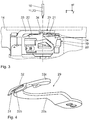
- a sewing machine 1 designed in particular as a lockstitch sewing machine has a base plate 2 with a stand 3 extending upward therefrom and an angled arm 4. The latter ends in a head 5.
- an arm shaft 6 is rotatably mounted.
- the crank mechanism 7 is drivingly connected to a needle bar 9 axially slidably mounted in the head 5 in connection.
- the needle 10 is moved by the crank mechanism 7 on a vertical axis 11 up and down.
- the needle 10 leads in an eye from a spool 12 via a thread tensioning device and the thread lever 8 supplied needle thread 13, which is also referred to as needle thread.
- the base plate 2 carries a screw-mounted support plate 14, on which a two-ply workpiece 15 rests.
- the support plate 14 is formed with a recess 16 for the passage of a feed dog 17, which is also referred to as Untertransporteur.
- the latter has a tap hole 18 for the passage of the needle 10th
- the feed dog 17 with respect to the fabric part 15 opposite a presser foot 17a is arranged.
- the x-direction which runs along a sewing direction, runs in the Fig. 1 perpendicular to the drawing plane into this.
- the y-direction runs in the Fig. 1 to the left.
- the feed dog or sub-feed 17 transports the workpiece 15 during a sewing along the sewing direction in the positive x-direction.
- the feed dog 17 is in a known manner in drive connection with a arranged below the base plate 2 thrust and screw jack.
- a gear for the sub-feed dog 17 can be designed as a stitch actuator gear and in particular as a link gear, like in the EP 2 330 241 B1 described.
- Such Stichstellergetriebe represents a Transporteurgetriebe, on which in particular a transport length of the Untertransporteurs 17 can be adjusted, so a stitch length in the seam production.
- the Stichstellergetriebe is part of a drive for displacing the Untertransporteurs 17 along the sewing direction x.
- the displacement drive is in the Fig. 1 shown schematically at 18a.
- the displacement drive 18a acts as well as the other driven components of the sewing machine 1 with a in the Fig.
- the control device 18b is in direct connection with these components of the sewing machine 1 to be controlled, and in particular with the displacement drive 18a in a manner not shown.
- Part of the displacement drive 18a is a swivel drive for a stitcher shaft of the stitch actuator transmission.
- a Stichstellerwelle is particularly in connection with the Fig. 2 of the EP 2 330 241 B1 described, the contents of which are hereby incorporated by reference.
- the pivot drive is thus an adjusting the Stichstellergetriebes for a transport length of the Untertransporteurs 17th
- a gripper 19 having a gripper body 20 with a gripper tip 21.
- a cup-shaped coil housing 22 is mounted for receiving a looper thread supply.
- a looper thread is also referred to below as a lower thread.
- the gripper 19 is rotatable about a vertical gripper axis 23.
- a sewing operation direction of rotation 24 runs in Fig. 2 in the clockwise direction around the gripper axis 23 extending along the z-direction.
- the gripper body 20 is fixedly connected to a shaft 25, which runs coaxially with the gripper axis 23.
- the shaft 25 is rotatably mounted in a bearing block 26 screwed to the base plate 2.
- a drive shaft 27 is mounted, which is connected to a arranged in the interior of the bearing block 26 gear transmission.
- the gear transmission has a gear ratio of 1: 2, so that in one revolution of the drive shaft 27 located on the shaft 25 gripper body 20 rotates twice.
- the drive shaft 27 is drivingly connected to the arm shaft 6 via a belt drive 28.
- a thread-pulling knife 29 is used to cut off the looper thread.
- the thread-pulling knife 29 is located between an in Fig. 2 illustrated basic position and a thread detection position about a parallel to the gripper axis 23 pivot axis 30 pivotally.
- the thread-pulling knife 29 has one in the view Fig. 2 pronounced of a sickle basic form, the free end in the basic position in the view after Fig. 2 extends around the coil housing 22 around.
- the stitch hole 18 is adjacent to a detection groove 31 (see FIG. Fig. 4 ) of the thread-pulling knife 29 with a groove bottom-side cutting edge 32.
- the detection groove 31 is executed in a right angle with respect to a horizontally extending base body 32a angled edge portion 32b of the thread-pulling knife 29.
- An extended free end portion 32c of the thread-pulling knife 29 is shown in FIG Fig. 2 executed rounded end.
- a fixed counter knife 33 Fixed to the base plate 2 on a boom is a fixed counter knife 33 (see. Fig. 3 ), which cooperates with the cutting edge 32 of the thread-pulling knife 29 for cutting the thread during the pivoting of the thread-pulling knife 29 from the thread-detecting position into the basic position.
- a counter-cutting edge 34 of the counter knife 33 which cooperates with the cutting edge 32 of the thread-pulling knife 29 during thread cutting, extends vertically along the z-direction.
- the Fig. 5 and 6 each show an instantaneous position of components of the sewing machine 1 on the one hand in a position "short forward stitch" ( Fig. 5 ) and on the other hand in the "reverse stitch” position ( Fig. 6 .). Both current positions after the Fig. 5 and 6 show cutting positions, so are reproduced at the time immediately before the cutting of the upper thread 13 and the lower thread 35 between the cutting edge 32 of the thread pulling knife 29 and the counter knife 34 of the counter knife 33. Also shown is the course of the upper thread 13 and on the other hand, the lower thread 35 during the Last stitches S 1 to S 5 in the fabric 15.
- the sub-feed 17 is also shown broken in the area of the stitch hole 18 to allow the view of underlying sections of the thread-pulling knife 29 and the counter knife 33.
- the Fig. 5 and 6 also show details of a movement guidance of the undertread 17 with a bottom feed carrier 36, a feed shaft 37, via which a transport stroke extending along the x direction is transmitted to the bottom feed dog 17, and a feed dog stroke 38, via which a feed unit acting along the z direction or Austauchhub is exerted on the sub-feed 17.
- the displacement drive 18a the one in the Fig. 5 and 6 invisible Stichstellerwelle acts, is in the Fig. 5 and 6 not shown.
- Fig. 5 shows the current position in a normal operation of the sewing machine 1, are generated with the short seam end threads.
- the stitch regulator gear is changed with the displacement drive 18a before formation of the fifth stitch S 5 to the "Short forward stitch", so that this last stitch S 5 is shorter than the stitches previously generated S 1 to S. 4
- both the upper thread 13 and the lower thread 35 extend toward the cut-off position between the cutting edge 32 and the counter knife cutting edge 34.
- the lower thread 35 runs along an approximately U-shaped course around a section delimiting the stitch hole 18 39 of the Untertransporteurs 17 around.
- Fig. 6 shows the corresponding components of the sewing machine 1 in the stitch regulator gear position "reverse stitch", also after formation of the executed as a short stitch stitch S 5th In this position, the Stichstellergetriebes a conversion is carried out by appropriate control of the displacement drive 18a.
- the sewing material part 15 is held stationary by the presser foot 17a relative thereto.
- a path between the last stitch S 5 and the cutting position between the cutting edges 32, 34 is now for the threads 13, 35 and in particular for the lower thread 35 at the instantaneous position Fig. 6 not as long as in the current position Fig. 5 , so that after the cutting of the threads 13, 35 smaller seam end threads on the fabric part 15 and in particular a shorter seam Endunterfaden results with a nominal seam projection of at most 10 mm.
- Fig. 7 shows a seam 40 which is produced with the sewing machine 1.
- the seam Endunterfaden 41 stands at the seam 40 from the last stitch S 5 with a nominal seam projection A of at most 10 mm.
- the method for producing such a seam end underneath with a nominal seam projection of at most 10 mm includes sewing the seam with the stitches Si, wherein prior to cutting the lower thread 35 at the seam end of the sub-conveyor 17 from the Näh istsleton, eg. From a position "Short Forward stitch "in a relation to this along the sewing direction x displaced cutting position, so for example the position" reverse stitch "is shifted. Subsequently, the lower thread 35 and the upper thread 13 are cut at the end of the seam with the thread-pulling knife 29 by cooperation of the cutting edges 32, 34.
- the Untertransporteur 17 can in comparison to the cutting position after Fig. 5 be displaced in a further cut position, which is displaced in the negative x-direction, so that a path on the one hand of the lower thread 35 and on the other hand, the upper thread 13 to the cutting position between the cutting edges 32, 34 extended even further.
- this position of the Untertransporteurs 17 may be the position "maximum forward stitch length". This results in correspondingly elongated seam end threads 13, 35.
- a stitch shortening, for example, the last stitch S 5 is not mandatory. It can therefore be sewn to the last stitch with normal stitch length, in which case immediately a change over of the Stichstellergetriebes from the position "normal forward stitch” in the cut position for the Untertransporteur 17, ie, for example, in the "backward stitch” position.
- the controller 18b is designed such that, synchronized at the end of sewing production, it controls the displacement drive 18a in such a way that the sub-conveyor 17 is displaced from the sewing operating position to the cutting position.
- the controller 18b is programmable to specify a residual bobbin thread length formed at the seam end.
- the displacement drive 18a is designed as a stepper motor. Alternatively, it is possible to design the displacement drive as a lifting magnet or as a pneumatic cylinder. In this case, at least one stop can be provided in order to specify a position of the stitch actuator transmission with activated lifting magnet or pneumatic cylinder. Such a stop can be made adjustable. It can also be more than one such attack be provided.
Abstract
Zum Erzeugen eines Naht-Endunterfadens mit einem Soll-Nahtüberstand von höchstens 10 mm wird vor einem Abschneiden eines Unterfadens (35) an einem Ende einer Naht ein Untertransporteur (17) aus einer Nähbetriebsstellung in eine gegenüber dieser längs einer Nährichtung (x) verlagerten Abschneidestellung umgestellt. Anschließend wird am Ende der Naht der Unterfaden (35) abgeschnitten. Eine Nähmaschine zur Durchführung dieses Verfahrens hat eine Steuerung zum Ansteuern eines Verlagerungsantriebs, die derart ausgebildet ist, dass sie synchronisiert am Ende einer Nahterzeugung den Verlagerungsantrieb zur Verlagerung des Untertransporteurs (17) von der Nähbetriebsstellung in die Abschneidestellung ansteuert. Es resultiert ein Erzeugungsverfahren für einen Naht-Endunterfaden mit vorgegebenem Soll-Nahtüberstand, bei dem der Naht-Endunterfaden und damit auch der Soll-Nahtüberstand kürzer gestaltet werden kann, und eine Nähmaschine zur Durchführung des Verfahrens.To produce a seam end lower thread with a desired seam protrusion of at most 10 mm, a sub-conveyor (17) is switched from a sewing operation position to a cut-off position displaced with respect to this along a sewing direction (x) before cutting off a lower thread (35) at one end of a seam , Subsequently, the lower thread (35) is cut off at the end of the seam. A sewing machine for carrying out this method has a controller for driving a displacement drive, which is designed such that it controls the displacement drive for shifting the Untertransporteurs (17) from the Nähbetriebsstellung in the cutting position synchronized at the end of a Nahterzeugung. The result is a production method for a seam Endunterfaden with predetermined target seam projection, in which the seam Endunterfaden and thus also the desired seam projection can be made shorter, and a sewing machine for performing the method.
Description
Die vorliegende Erfindung nimmt die Priorität der deutschen Patentanmeldung
Die Erfindung betrifft ein Verfahren zum Erzeugen eines Naht-Endunterfadens mit vorgegebenem Soll-Nahtüberstand. Ferner betrifft die Erfindung eine Nähmaschine zur Durchführung eines derartigen Verfahrens.The invention relates to a method for producing a seam end lower thread with a predetermined desired seam projection. Furthermore, the invention relates to a sewing machine for carrying out such a method.
Eine Nähmaschine, mit der ein Naht-Endunterfaden mit vorgegebenem Soll-Nahtüberstand erzeugt werden kann, ist bekannt aus der
Es ist eine Aufgabe der vorliegenden Erfindung, ein Verfahren zum Erzeugen eines Naht-Endunterfadens mit vorgegebenem Soll-Nahtüberstand derart weiterzubilden, dass der Naht-Endunterfaden und somit auch der Soll-Nahtüberstand kürzer gestaltet werden kann.It is an object of the present invention to develop a method for producing a seam end lower thread with a predetermined desired seam projection in such a way that the seam end lower thread and thus also the desired seam projection can be made shorter.
Diese Aufgabe ist erfindungsgemäß gelöst durch ein Erzeugungsverfahren mit den im Anspruch 1 angegebenen Merkmalen.This object is achieved by a production method having the features specified in
Erfindungsgemäß wurde erkannt, dass die Position eines Untertransporteurs nach dem Ausbilden einer Naht und vor dem Abschneiden des Unterfadens am Nahtende so verlagert werden kann, dass ein Unterfadenweg zwischen dem letzten Stich der Naht und einer Abschneideposition verkürzt werden kann. Es resultiert ein entsprechend verkürzter Naht-Endunterfaden. Diese Verkürzung ist aufgrund der klar definierbaren Position des Untertransporteurs in der Abschneidestellung exakt reproduzierbar, so dass abhängig von der Stellung des Untertransporteurs ein vorgegebener Soll-Nahtüberstand resultiert. Gleichzeitig mit der Erzeugung eines Naht-Endunterfadens mit einem Soll-Nahtüberstand kann auch ein Naht-Endoberfaden mit einem vergleichbaren Soll-Nahtüberstand, beispielsweise von höchstens 10 mm erzeugt werden. Der Oberfaden kann bei dem Erzeugungsverfahren gleichzeitig mit dem Unterfaden abgeschnitten werden. Durch die Umstellung des Untertransporteurs aus der Nähbetriebsstellung in die Abschneidestellung kann dann vor dem Abschneiden des Oberfadens ein Oberfadenweg zwischen dem letzten Stich der Naht und der Abschneideposition verkürzt werden, was zu einem entsprechend verkürzten Naht-Endoberfaden führt. Es resultiert ein entsprechend vorgebbarer Soll-Nahtüberstand des Naht-Endoberfadens abhängig von der Stellung des Untertransporteurs. Durch entsprechende Umstellung des Untertransporteurs in eine Abschneidestellung, bei der ein Unterfadenweg und/oder ein Oberfadenweg zwischen dem letzten Stich der Naht und der Abschneideposition verlängert wird, kann auch gezielt ein Naht-Endunterfaden und/oder ein Naht-Endoberfaden mit einem verlängerten Soll-Nahtüberstand, beispielsweise von deutlich mehr als 10 mm, erzeugt werden. Dies kann für bestimmte Nähaufgaben, bei denen längere Naht-Endfäden gewünscht sind, sinnvoll sein. Bei dem Untertransporteur kann es sich um einen Stoffschieber handeln. Der Untertransporteur kann zusammen mit Stichbildungswerkzeugen der Nähmaschine, also einer Nähnadel sowie einem Greifer, synchronisiert und/oder periodisch arbeiten. Der Untertransporteur stellt eine Komponente da, die das Nähgut durch reibschlüssigen Kontakt von unten her in der Nährichtung transportiert. Dabei kommt der Untertransporteur während einer Stichperiode während eines Zeitabschnitts in Eingriff mit dem Nähgut und ist während eines weiteren Zeitabschnitts außer Eingriff mit dem Nähgut.According to the invention, it has been recognized that the position of a sub-conveyor after forming a seam and before cutting the lower thread at the seam end can be displaced so that a lower thread path between the last stitch of the seam and a cut-off position can be shortened. This results in a correspondingly shortened seam end lower thread. This shortening is exactly reproducible due to the clearly definable position of the bottom conveyor in the cutting position, so that, depending on the position of the lower transporter, a predetermined target seam projection results. Simultaneously with the generation of a seam end lower thread with a desired seam projection, a seam end upper thread with a comparable desired seam projection, for example of at most 10 mm, can also be produced. The upper thread can be cut simultaneously with the lower thread in the production process. By switching the Untertransporteurs from the Nähbetriebsstellung in the cutting position then a top thread path between the last stitch of the seam and the cutting position can be shortened before cutting the upper thread, resulting in a correspondingly shortened seam Endoberfaden. The result is a correspondingly predetermined target seam projection of the seam end upper thread depending on the position of the Untertransporteurs. By corresponding conversion of the undertread into a cut-off position in which a lower thread path and / or a upper thread path is extended between the last stitch of the seam and the cut-off position, a seam end lower thread and / or a seam end upper thread with an extended nominal seam projection can also be targeted , for example, significantly more than 10 mm, are generated. This can be useful for certain sewing tasks where longer seam end threads are desired. The sub-feed dog may be a feed dog. The sub-feed dog can work together with stitching tools of the sewing machine, ie a sewing needle and a gripper, synchronized and / or periodically. The sub-feed provides a component that transports the fabric by frictional contact from below in the sewing direction. In this case, the sub-feed dog engages with the sewing material during a stitching period during a period of time and is out of engagement with the sewing material for a further period of time.
Ein Kurzstich vor dem Abschneiden nach Anspruch 2 führt dazu, dass ein mit dem Abschneiden erzeugter Naht-Endunterfaden sowie ein Naht-Endoberfaden vom Nähgut bis zur Abschneideposition einen vergleichbar langen Weg nehmen und daher aufgrund des letzten Kurzstichs praktisch gleichlang sind.A short stitch before cutting according to
Ein Umstellen nach Anspruch 3 kann je nach Ausgestaltung der Nähmaschine zu einer vorteilhaften Verkürzung des Unterfadenwegs zwischen dem letzten Stich und der Abschneideposition führen. Als Abschneidestellung für den Untertransporteur kann die Stellung "Rückwärtsstich" gewählt werden.A changeover according to
Ein Umstellen nach Anspruch 4 lässt sich in den Normalbetrieb einer Nähmaschine integrieren. Ein zusätzlicher Umstellantrieb kann dann entfallen.A changeover according to
Eine weitere Aufgabe der Erfindung ist, eine Nähmaschine zur Durchführung des erfindungsgemäßen Verfahrens anzugeben.Another object of the invention is to provide a sewing machine for carrying out the method according to the invention.
Diese Aufgabe ist erfindungsgemäß gelöst durch eine Nähmaschine mit den in Anspruch 5 angegebenen Merkmalen.This object is achieved by a sewing machine with the features specified in
Die Vorteile der Nähmaschine entsprechen denen, die vorstehend unter Bezugnahme auf das erfindungsgemäße Verfahren bereits erläutert wurden. Der Antrieb zum Verlagern des Untertransporteurs kann dann das Stellmittel eines Transporteurgetriebes darstellen.The advantages of the sewing machine correspond to those which have already been explained above with reference to the method according to the invention. The drive for displacing the Untertransporteurs can then represent the actuating means of a transport company.
Die Steuerung zum Ansteuern des Verlagerungsantriebes kann zur Vorgabe einer Rest-Unterfadenlänge am Nahtende programmierbar gestaltet sein. Die Rest-Unterfadenlänge kann mittels eines Bedienelements an der Nähmaschine vorgewählt werden.The control for controlling the displacement drive can be designed programmable to specify a residual bobbin thread length at the seam end. The remaining bobbin thread length can be preselected by means of a control element on the sewing machine.
Ein Stichstellergetriebe nach Anspruch 6 ist als ansteuerbarer Verlagerungsantrieb zum Umstellen des Untertransporteurs aus der Nähbetriebsstellung in die Abschneidestellung besonders geeignet. Das Stichstellergetriebe kann insbesondere als Laschengetriebe ausgeführt sein. Ein derart geeignetes Stichstellergetriebe ist bekannt aus der
Ein Schwenkantrieb nach Anspruch 7 stellt einen besonders einfachen Antrieb zum Umstellen des Untertransporteurs aus der Nähbetriebsstellung in die Abschneidestellung dar. Der Schwenkantrieb kann als Schrittmotor ausgeführt sein. Alternativ kann der Schwenkantrieb als Hubmagnet oder als Pneumatikzylinder ausgeführt sein. Der Schwenkantrieb kann mit mindestens einem Anschlag zur Vorgabe mindestens einer Untertransporteurstellung zusammenwirken. Der Anschlag kann einstellbar sein. Auch mehrere derartige Anschläge können vorgesehen sein.A rotary actuator according to claim 7 represents a particularly simple drive for switching the Untertransporteurs from the Nähbetriebsstellung in the cut position. The pivot drive can be designed as a stepper motor. Alternatively, the rotary actuator can be designed as a solenoid or as a pneumatic cylinder. The rotary actuator can cooperate with at least one stop to specify at least one Untertransporteurstellung. The stop can be adjustable. Also, several such attacks can be provided.
Ausführungsbeispiele der Erfindung werden nachfolgend anhand der Zeichnung näher erläutert. In dieser zeigen:
- Fig. 1
- eine Vorderansicht einer Doppelsteppstichnähmaschine;
- Fig. 2
- eine Draufsicht auf einen Ausschnitt der Nähmaschine in vergrößertem Maßstab entsprechend dem Sichtpfeil II in
Fig. 1 ; - Fig. 3
- eine innere Details freigebende Stirnansicht auf einen Ausschnitt der Nähmaschine entsprechend dem Sichtpfeil III in
Fig. 1 in vergrößertem Maßstab; - Fig. 4
- eine perspektivische Darstellung eines Fadenziehmessers;
- Fig. 5
- einen Schnitt gemäß Linie V-V in
Fig. 1 in einer Momentanposition eines Untertransporteurs und eines Fadenziehmessers beim Abschneiden eines Unterfadens an einem Ende einer Naht zur Erzeugung eines Naht-Endunterfadens mit einem Soll-Nahtüberstand nach dem Stand der Technik; - Fig. 6
- in einer zur
Fig. 5 ähnlichen Darstellung einer Momentanposition des Untertransporteurs und des Fadenziehmessers beim Abschneiden des Unterfadens am Nahtende zum Erzeugen des Naht-Endunterfadens mit Soll-Nahtüberstand von höchstens 10mm; und - Fig. 7
- schematisch eine Aufsicht auf eine mit der Nähmaschine genähten Naht zur Veranschaulichung eines erzeugten NahtEndunterfadens mit einem vorgegebenen Soll-Nahtüberstand.
- Fig. 1
- a front view of a lockstitch sewing machine;
- Fig. 2
- a plan view of a section of the sewing machine in an enlarged scale corresponding to the viewing arrow II in
Fig. 1 ; - Fig. 3
- an inner details releasing front view of a section of the sewing machine according to the viewing arrow III in
Fig. 1 on an enlarged scale; - Fig. 4
- a perspective view of a thread-pulling knife;
- Fig. 5
- a section along line VV in
Fig. 1 in an instantaneous position of a bottom transporter and a thread-pulling knife in cutting a bottom thread at one end of a seam to produce a seam end thread with a desired seam overhang of the prior art; - Fig. 6
- in a to
Fig. 5 similar representation of an instantaneous position of the lower transporter and the thread-pulling knife when cutting the lower thread at the seam end to produce the seam end lower thread with nominal seam projection of at most 10 mm; and - Fig. 7
- schematically a plan view of a stitched seam with the sewing machine to illustrate a generated seam end underneath thread with a predetermined target seam projection.
Eine insbesondere als Doppelsteppstichnähmaschine ausgebildete Nähmaschine 1 hat eine Grundplatte 2 mit einem sich davon aufwärts erstreckenden Ständer 3 und einem abgewinkelten Arm 4. Letzterer endet in einem Kopf 5. In dem Arm 4 ist eine Armwelle 6 drehbar gelagert. Diese treibt in dem Kopf 5 einen Kurbeltrieb 7 mit einem Fadenhebel 8 an. Der Kurbeltrieb 7 steht antriebsmäßig mit einer in dem Kopf 5 axial verschiebbar gelagerten Nadelstange 9 in Verbindung. Diese hat an ihrem unteren Ende eine Nadel 10. Die Nadel 10 ist durch den Kurbeltrieb 7 auf einer vertikalen Achse 11 auf- und ab bewegbar. Die Nadel 10 führt in einem Öhr einen von einer Spule 12 über eine Fadenspannvorrichtung und den Fadenhebel 8 zugeführten Nadelfaden 13, der auch als Oberfaden bezeichnet ist.A
Die Grundplatte 2 trägt eine mit Schrauben befestigte Auflageplatte 14, auf der ein zweilagiges Nähgutteil 15 aufliegt. Die Auflageplatte 14 ist mit einer Ausnehmung 16 für den Durchtritt eines Stoffschiebers 17 ausgebildet, der auch als Untertransporteur bezeichnet ist. Letzterer hat ein Stichloch 18 für den Durchtritt der Nadel 10.The
Dem Stoffschieber 17 in Bezug auf das Nähgutteil 15 gegenüberliegend ist ein Drückerfuß 17a angeordnet.The
Zur Verdeutlichung von Lagebeziehungen wird nachfolgend ein kartesisches xyz-Koordinatensystem verwendet. Die x-Richtung, die längs einer Nährichtung verläuft, verläuft in der
Der Stoffschieber 17 befindet sich in bekannter Weise in Antriebsverbindung mit einem unterhalb der Grundplatte 2 angeordneten Schub- und Hubgetriebe. Ein solches Getriebe für den Untertransporteur 17 kann als Stichstellergetriebe und insbesondere als Laschengetriebe ausgeführt sein, wie in der
Unterhalb der Auflageplatte 14 befindet sich ein Greifer 19, der einen Greiferkörper 20 mit einer Greiferspitze 21 aufweist. In dem Greiferkörper 20 ist ein topfförmiges Spulengehäuse 22 zur Aufnahme eines Greiferfadenvorrats gelagert. Ein Greiferfaden wird nachfolgend auch als Unterfaden bezeichnet.Below the
Der Greifer 19 ist um eine vertikale Greiferachse 23 drehbar. Eine Nähbetriebs-Drehrichtung 24 verläuft in
Zum Abschneiden des Greiferfadens dient ein Fadenziehmesser 29. Das Fadenziehmesser 29 ist zwischen einer in
An der Grundplatte 2 an einem Ausleger festgelegt ist ein ortsfestes Gegenmesser 33 (vgl.
Eine Gegenschneidkante 34 des Gegenmessers 33, die beim Fadenabschneiden mit der Schneide 32 des Fadenziehmessers 29 zusammenwirkt, verläuft vertikal längs der z-Richtung.A
Die
Aufgrund der Stellung "Rückwärtsstich" ist die Transporteurwelle 37 in der
Das Verfahren zum Erzeugen eines derartigen Naht-Endunterfadens mit einem Soll-Nahtüberstand von höchstens 10 mm beinhaltet das Nähen der Naht mit den Stichen Si, wobei vor dem Abschneiden des Unterfadens 35 am Nahtende der Untertransporteur 17 aus der Nähbetriebsstellung, z.B. aus einer Stellung "Kurzer Vorwärtsstich" in eine gegenüber dieser längs der Nährichtung x verlagerten Abschneidestellung, also beispielsweise der Stellung "Rückwärtsstich" verlagert wird. Anschließend werden der Unterfaden 35 und der Oberfaden 13 am Ende der Naht mit dem Fadenziehmesser 29 durch Zusammenwirken der Schneiden 32, 34 abgeschnitten.The method for producing such a seam end underneath with a nominal seam projection of at most 10 mm includes sewing the seam with the stitches Si, wherein prior to cutting the
Der Untertransporteur 17 kann im Vergleich zur Abschneidestellung nach
Eine Stichverkürzung beispielsweise beim letzten Stich S5 ist dabei nicht zwingend. Es kann also bis zum letzten Stich auch mit normaler Stichlänge genäht werden, wobei dann unmittelbar ein Umstellen des Stichstellergetriebes von der Stellung "Normaler Vorwärtsstich" in die Abschneidestellung für den Untertransporteur 17, also beispielsweise in die Stellung "Rückwärtsstich" erfolgt.A stitch shortening, for example, the last stitch S 5 is not mandatory. It can therefore be sewn to the last stitch with normal stitch length, in which case immediately a change over of the Stichstellergetriebes from the position "normal forward stitch" in the cut position for the
Die Steuerung 18b ist derart ausgebildet, dass sie synchronisiert am Ende der Nahterzeugung den Verlagerungsantrieb 18a derart ansteuert, dass der Untertransporteur 17 von der Nähbetriebsstellung in die Abschneidestellung verlagert wird. Die Steuerung 18b ist dabei programmierbar zur Vorgabe einer Rest-Unterfadenlänge am Nahtende ausgebildet.The
Der Verlagerungsantrieb 18a ist als Schrittmotor ausgebildet. Alternativ ist es möglich, den Verlagerungsantrieb als Hubmagneten oder als Pneumatikzylinder auszugestalten. Dabei kann mindestens ein Anschlag vorgesehen sein, um eine Position des Stichstellergetriebes bei aktiviertem Hubmagneten bzw. Pneumatikzylinder vorzugeben. Ein derartiger Anschlag kann verstellbar ausgeführt sein. Es kann auch mehr als ein derartiger Anschlag vorgesehen sein.The displacement drive 18a is designed as a stepper motor. Alternatively, it is possible to design the displacement drive as a lifting magnet or as a pneumatic cylinder. In this case, at least one stop can be provided in order to specify a position of the stitch actuator transmission with activated lifting magnet or pneumatic cylinder. Such a stop can be made adjustable. It can also be more than one such attack be provided.
Claims (7)
Applications Claiming Priority (1)
| Application Number | Priority Date | Filing Date | Title |
|---|---|---|---|
| DE102017207626.7A DE102017207626A1 (en) | 2017-05-05 | 2017-05-05 | Method for producing a seam end lower thread with a predetermined desired seam protrusion |
Publications (2)
| Publication Number | Publication Date |
|---|---|
| EP3399089A1 true EP3399089A1 (en) | 2018-11-07 |
| EP3399089B1 EP3399089B1 (en) | 2022-01-12 |
Family
ID=62046696
Family Applications (1)
| Application Number | Title | Priority Date | Filing Date |
|---|---|---|---|
| EP18168646.0A Active EP3399089B1 (en) | 2017-05-05 | 2018-04-23 | Method and sewing machine for generating a bobbin thread end of a seam with a predetermined protrusion |
Country Status (5)
| Country | Link |
|---|---|
| EP (1) | EP3399089B1 (en) |
| KR (1) | KR102496910B1 (en) |
| CN (1) | CN108796854A (en) |
| DE (1) | DE102017207626A1 (en) |
| TW (1) | TWI775849B (en) |
Citations (8)
| Publication number | Priority date | Publication date | Assignee | Title |
|---|---|---|---|---|
| DE1104805B (en) * | 1960-04-04 | 1961-04-13 | Pfaff Ag G M | Process for cutting the upper and lower thread on lockstitch sewing machines and device for carrying out the process |
| DE19746653C1 (en) * | 1997-10-22 | 1998-11-12 | Pfaff Ag G M | Sewing machine thread cutting |
| DE10215011A1 (en) * | 2001-04-13 | 2002-11-21 | Juki Kk | Button hole-stitching sewing machine clamps looper thread for cutting and returns looper thread holder to original position before releasing clamp after cutting |
| DE102008030620B3 (en) * | 2008-06-24 | 2009-12-24 | Pfaff Industrie Maschinen Ag | Method and device for cutting the needle and the hook thread on lockstitch sewing machines with gripper rotating in a horizontal plane |
| EP2540893A1 (en) * | 2011-07-01 | 2013-01-02 | Nähmaschinenfabrik Emil Stutznäcker GmbH & Co. KG | Method for operating a chain-stitch sewing machine and chain-stitch sewing machine |
| DE202015102172U1 (en) * | 2015-04-30 | 2016-08-04 | Dürkopp Adler AG | sewing machine |
| DE102016102024A1 (en) * | 2015-02-06 | 2016-08-11 | Juki Corporation | sewing machine |
| DE102015223194B3 (en) * | 2015-11-24 | 2017-02-23 | Dürkopp Adler AG | A method for creating a seam beginning upper thread with short target seam projection and assembly for performing the method |
Family Cites Families (11)
| Publication number | Priority date | Publication date | Assignee | Title |
|---|---|---|---|---|
| JP2000317178A (en) * | 1999-05-07 | 2000-11-21 | Juki Corp | Thread cutter device |
| CH697309B1 (en) * | 2005-05-09 | 2008-08-15 | Gegauf Fritz Ag | Device for actuating a plurality of functions of a sewing machine. |
| CN2799611Y (en) * | 2005-05-24 | 2006-07-26 | 顾飞龙 | Thread hooking and clamping device for sewing machine |
| DE202006009410U1 (en) * | 2006-04-21 | 2007-08-30 | Dürkopp Adler AG | Thread-pulling knife for a sewing machine |
| CN101845724B (en) * | 2009-03-27 | 2013-03-06 | 兄弟工业株式会社 | Sewing machine |
| DE102009036988A1 (en) * | 2009-05-12 | 2010-12-16 | Nähmaschinenfabrik Emil Stutznäcker GmbH & Co. KG | Method for sewing a sewing material |
| DE102009039252A1 (en) * | 2009-08-28 | 2011-03-10 | Dürkopp Adler AG | sewing machine |
| DE102009047534A1 (en) * | 2009-12-04 | 2011-06-09 | Dürkopp Adler AG | sewing machine |
| DE102013007928A1 (en) * | 2013-05-12 | 2014-11-13 | Pfaff Industriesysteme Und Maschinen Ag | Sewing machine for the production of seams with short initial yarn lengths |
| CN203668663U (en) * | 2013-12-31 | 2014-06-25 | 上海标准海菱缝制机械有限公司 | Short thread end automatic trimming device of sewing machine |
| CN204509696U (en) * | 2014-12-25 | 2015-07-29 | 上海标准海菱缝制机械有限公司 | A kind of Sewing machines short-term head automatic thread trimming device |
-
2017
- 2017-05-05 DE DE102017207626.7A patent/DE102017207626A1/en not_active Withdrawn
-
2018
- 2018-04-23 EP EP18168646.0A patent/EP3399089B1/en active Active
- 2018-05-02 KR KR1020180050557A patent/KR102496910B1/en active IP Right Grant
- 2018-05-03 CN CN201810414871.6A patent/CN108796854A/en active Pending
- 2018-05-04 TW TW107115290A patent/TWI775849B/en active
Patent Citations (8)
| Publication number | Priority date | Publication date | Assignee | Title |
|---|---|---|---|---|
| DE1104805B (en) * | 1960-04-04 | 1961-04-13 | Pfaff Ag G M | Process for cutting the upper and lower thread on lockstitch sewing machines and device for carrying out the process |
| DE19746653C1 (en) * | 1997-10-22 | 1998-11-12 | Pfaff Ag G M | Sewing machine thread cutting |
| DE10215011A1 (en) * | 2001-04-13 | 2002-11-21 | Juki Kk | Button hole-stitching sewing machine clamps looper thread for cutting and returns looper thread holder to original position before releasing clamp after cutting |
| DE102008030620B3 (en) * | 2008-06-24 | 2009-12-24 | Pfaff Industrie Maschinen Ag | Method and device for cutting the needle and the hook thread on lockstitch sewing machines with gripper rotating in a horizontal plane |
| EP2540893A1 (en) * | 2011-07-01 | 2013-01-02 | Nähmaschinenfabrik Emil Stutznäcker GmbH & Co. KG | Method for operating a chain-stitch sewing machine and chain-stitch sewing machine |
| DE102016102024A1 (en) * | 2015-02-06 | 2016-08-11 | Juki Corporation | sewing machine |
| DE202015102172U1 (en) * | 2015-04-30 | 2016-08-04 | Dürkopp Adler AG | sewing machine |
| DE102015223194B3 (en) * | 2015-11-24 | 2017-02-23 | Dürkopp Adler AG | A method for creating a seam beginning upper thread with short target seam projection and assembly for performing the method |
Also Published As
| Publication number | Publication date |
|---|---|
| KR102496910B1 (en) | 2023-02-06 |
| TWI775849B (en) | 2022-09-01 |
| CN108796854A (en) | 2018-11-13 |
| TW201900973A (en) | 2019-01-01 |
| KR20180122950A (en) | 2018-11-14 |
| DE102017207626A1 (en) | 2018-11-08 |
| EP3399089B1 (en) | 2022-01-12 |
Similar Documents
| Publication | Publication Date | Title |
|---|---|---|
| DE102008027015B4 (en) | Embroidery machine and dedicated control method | |
| DE102006041825B4 (en) | Apparatus and method for cutting a sewing material in a sewing machine | |
| DE102009004217A1 (en) | Two-needle sewing machine | |
| DE3743281C2 (en) | ||
| DE3302385A1 (en) | HOLE SEWING MACHINE | |
| DE19916660C1 (en) | Buttonhole sewing machine has a control unit which determines the operation of the drives for cutting and stitching buttonholes of different shapes and/or sizes without manual resetting | |
| EP3176296B1 (en) | Method for creating an initial upper thread of a seam with short seam width | |
| DE2507544A1 (en) | AUTOMATIC SEWING MACHINE | |
| DE10136543C1 (en) | Buttonhole sewing machine has a clamp/cutter unit for the upper thread, mounted at a body containing cutter swing and closing drives, in a simple and low-cost structure | |
| DE102017204979A1 (en) | Combined sewing machine | |
| EP1384806B1 (en) | Method and sewing machine for drawing the free end of a needle thread from the upper surface of a piece of fabric to its lower surface | |
| DE102009004218A1 (en) | Thread cutting device for a sewing machine | |
| DE102007019944A1 (en) | Sewing machine hem accessory has marking spotlamp linked to follower regulator | |
| DE10262216B4 (en) | Buttonhole sewing machine | |
| DE102007020139B4 (en) | hemming | |
| EP3360994A1 (en) | Double-lock-stitch sewing machine and method for generating an upper seam start thread with a low protrusion | |
| WO2023242171A1 (en) | Sewing unit | |
| EP2182102B1 (en) | Sewing machine | |
| EP3399089B1 (en) | Method and sewing machine for generating a bobbin thread end of a seam with a predetermined protrusion | |
| WO2013068126A2 (en) | Sewing machine having a holding down clamp for material to be sewed | |
| EP3088589A1 (en) | Sewing installation and method for the operation of same | |
| EP3399088B1 (en) | Assembly and sewing machine for producing a starting upper thread with a set protrusion | |
| DE102009004216B3 (en) | Two-needle-sewing machine, has switch cam designed such that switching-effective surface causes pendulum motion of switch of needle bars, where pendulum motion is carried out based on transportation of sewing needles | |
| EP2453050A1 (en) | Sewing machine and method for sewing a beginning of a seam with such a sewing machine | |
| EP2206820B1 (en) | Thread cutting device |
Legal Events
| Date | Code | Title | Description |
|---|---|---|---|
| PUAI | Public reference made under article 153(3) epc to a published international application that has entered the european phase |
Free format text: ORIGINAL CODE: 0009012 |
|
| STAA | Information on the status of an ep patent application or granted ep patent |
Free format text: STATUS: THE APPLICATION HAS BEEN PUBLISHED |
|
| AK | Designated contracting states |
Kind code of ref document: A1 Designated state(s): AL AT BE BG CH CY CZ DE DK EE ES FI FR GB GR HR HU IE IS IT LI LT LU LV MC MK MT NL NO PL PT RO RS SE SI SK SM TR |
|
| AX | Request for extension of the european patent |
Extension state: BA ME |
|
| STAA | Information on the status of an ep patent application or granted ep patent |
Free format text: STATUS: REQUEST FOR EXAMINATION WAS MADE |
|
| 17P | Request for examination filed |
Effective date: 20190201 |
|
| RBV | Designated contracting states (corrected) |
Designated state(s): AL AT BE BG CH CY CZ DE DK EE ES FI FR GB GR HR HU IE IS IT LI LT LU LV MC MK MT NL NO PL PT RO RS SE SI SK SM TR |
|
| STAA | Information on the status of an ep patent application or granted ep patent |
Free format text: STATUS: REQUEST FOR EXAMINATION WAS MADE |
|
| GRAP | Despatch of communication of intention to grant a patent |
Free format text: ORIGINAL CODE: EPIDOSNIGR1 |
|
| STAA | Information on the status of an ep patent application or granted ep patent |
Free format text: STATUS: GRANT OF PATENT IS INTENDED |
|
| INTG | Intention to grant announced |
Effective date: 20210924 |
|
| GRAS | Grant fee paid |
Free format text: ORIGINAL CODE: EPIDOSNIGR3 |
|
| GRAA | (expected) grant |
Free format text: ORIGINAL CODE: 0009210 |
|
| STAA | Information on the status of an ep patent application or granted ep patent |
Free format text: STATUS: THE PATENT HAS BEEN GRANTED |
|
| AK | Designated contracting states |
Kind code of ref document: B1 Designated state(s): AL AT BE BG CH CY CZ DE DK EE ES FI FR GB GR HR HU IE IS IT LI LT LU LV MC MK MT NL NO PL PT RO RS SE SI SK SM TR |
|
| REG | Reference to a national code |
Ref country code: GB Ref legal event code: FG4D Free format text: NOT ENGLISH |
|
| REG | Reference to a national code |
Ref country code: CH Ref legal event code: EP |
|
| REG | Reference to a national code |
Ref country code: DE Ref legal event code: R096 Ref document number: 502018008482 Country of ref document: DE |
|
| REG | Reference to a national code |
Ref country code: IE Ref legal event code: FG4D Free format text: LANGUAGE OF EP DOCUMENT: GERMAN |
|
| REG | Reference to a national code |
Ref country code: AT Ref legal event code: REF Ref document number: 1462455 Country of ref document: AT Kind code of ref document: T Effective date: 20220215 |
|
| REG | Reference to a national code |
Ref country code: RO Ref legal event code: EPE |
|
| REG | Reference to a national code |
Ref country code: LT Ref legal event code: MG9D |
|
| REG | Reference to a national code |
Ref country code: NL Ref legal event code: MP Effective date: 20220112 |
|
| PG25 | Lapsed in a contracting state [announced via postgrant information from national office to epo] |
Ref country code: NL Free format text: LAPSE BECAUSE OF FAILURE TO SUBMIT A TRANSLATION OF THE DESCRIPTION OR TO PAY THE FEE WITHIN THE PRESCRIBED TIME-LIMIT Effective date: 20220112 |
|
| PG25 | Lapsed in a contracting state [announced via postgrant information from national office to epo] |
Ref country code: SE Free format text: LAPSE BECAUSE OF FAILURE TO SUBMIT A TRANSLATION OF THE DESCRIPTION OR TO PAY THE FEE WITHIN THE PRESCRIBED TIME-LIMIT Effective date: 20220112 Ref country code: RS Free format text: LAPSE BECAUSE OF FAILURE TO SUBMIT A TRANSLATION OF THE DESCRIPTION OR TO PAY THE FEE WITHIN THE PRESCRIBED TIME-LIMIT Effective date: 20220112 Ref country code: PT Free format text: LAPSE BECAUSE OF FAILURE TO SUBMIT A TRANSLATION OF THE DESCRIPTION OR TO PAY THE FEE WITHIN THE PRESCRIBED TIME-LIMIT Effective date: 20220512 Ref country code: NO Free format text: LAPSE BECAUSE OF FAILURE TO SUBMIT A TRANSLATION OF THE DESCRIPTION OR TO PAY THE FEE WITHIN THE PRESCRIBED TIME-LIMIT Effective date: 20220412 Ref country code: LT Free format text: LAPSE BECAUSE OF FAILURE TO SUBMIT A TRANSLATION OF THE DESCRIPTION OR TO PAY THE FEE WITHIN THE PRESCRIBED TIME-LIMIT Effective date: 20220112 Ref country code: HR Free format text: LAPSE BECAUSE OF FAILURE TO SUBMIT A TRANSLATION OF THE DESCRIPTION OR TO PAY THE FEE WITHIN THE PRESCRIBED TIME-LIMIT Effective date: 20220112 Ref country code: ES Free format text: LAPSE BECAUSE OF FAILURE TO SUBMIT A TRANSLATION OF THE DESCRIPTION OR TO PAY THE FEE WITHIN THE PRESCRIBED TIME-LIMIT Effective date: 20220112 Ref country code: BG Free format text: LAPSE BECAUSE OF FAILURE TO SUBMIT A TRANSLATION OF THE DESCRIPTION OR TO PAY THE FEE WITHIN THE PRESCRIBED TIME-LIMIT Effective date: 20220412 |
|
| PG25 | Lapsed in a contracting state [announced via postgrant information from national office to epo] |
Ref country code: PL Free format text: LAPSE BECAUSE OF FAILURE TO SUBMIT A TRANSLATION OF THE DESCRIPTION OR TO PAY THE FEE WITHIN THE PRESCRIBED TIME-LIMIT Effective date: 20220112 Ref country code: LV Free format text: LAPSE BECAUSE OF FAILURE TO SUBMIT A TRANSLATION OF THE DESCRIPTION OR TO PAY THE FEE WITHIN THE PRESCRIBED TIME-LIMIT Effective date: 20220112 Ref country code: GR Free format text: LAPSE BECAUSE OF FAILURE TO SUBMIT A TRANSLATION OF THE DESCRIPTION OR TO PAY THE FEE WITHIN THE PRESCRIBED TIME-LIMIT Effective date: 20220413 Ref country code: FI Free format text: LAPSE BECAUSE OF FAILURE TO SUBMIT A TRANSLATION OF THE DESCRIPTION OR TO PAY THE FEE WITHIN THE PRESCRIBED TIME-LIMIT Effective date: 20220112 |
|
| PG25 | Lapsed in a contracting state [announced via postgrant information from national office to epo] |
Ref country code: IS Free format text: LAPSE BECAUSE OF FAILURE TO SUBMIT A TRANSLATION OF THE DESCRIPTION OR TO PAY THE FEE WITHIN THE PRESCRIBED TIME-LIMIT Effective date: 20220512 |
|
| REG | Reference to a national code |
Ref country code: DE Ref legal event code: R097 Ref document number: 502018008482 Country of ref document: DE |
|
| PG25 | Lapsed in a contracting state [announced via postgrant information from national office to epo] |
Ref country code: SM Free format text: LAPSE BECAUSE OF FAILURE TO SUBMIT A TRANSLATION OF THE DESCRIPTION OR TO PAY THE FEE WITHIN THE PRESCRIBED TIME-LIMIT Effective date: 20220112 Ref country code: SK Free format text: LAPSE BECAUSE OF FAILURE TO SUBMIT A TRANSLATION OF THE DESCRIPTION OR TO PAY THE FEE WITHIN THE PRESCRIBED TIME-LIMIT Effective date: 20220112 Ref country code: EE Free format text: LAPSE BECAUSE OF FAILURE TO SUBMIT A TRANSLATION OF THE DESCRIPTION OR TO PAY THE FEE WITHIN THE PRESCRIBED TIME-LIMIT Effective date: 20220112 Ref country code: DK Free format text: LAPSE BECAUSE OF FAILURE TO SUBMIT A TRANSLATION OF THE DESCRIPTION OR TO PAY THE FEE WITHIN THE PRESCRIBED TIME-LIMIT Effective date: 20220112 |
|
| PLBE | No opposition filed within time limit |
Free format text: ORIGINAL CODE: 0009261 |
|
| STAA | Information on the status of an ep patent application or granted ep patent |
Free format text: STATUS: NO OPPOSITION FILED WITHIN TIME LIMIT |
|
| PG25 | Lapsed in a contracting state [announced via postgrant information from national office to epo] |
Ref country code: AL Free format text: LAPSE BECAUSE OF FAILURE TO SUBMIT A TRANSLATION OF THE DESCRIPTION OR TO PAY THE FEE WITHIN THE PRESCRIBED TIME-LIMIT Effective date: 20220112 |
|
| REG | Reference to a national code |
Ref country code: CH Ref legal event code: PL |
|
| 26N | No opposition filed |
Effective date: 20221013 |
|
| GBPC | Gb: european patent ceased through non-payment of renewal fee |
Effective date: 20220423 |
|
| REG | Reference to a national code |
Ref country code: BE Ref legal event code: MM Effective date: 20220430 |
|
| PG25 | Lapsed in a contracting state [announced via postgrant information from national office to epo] |
Ref country code: MC Free format text: LAPSE BECAUSE OF FAILURE TO SUBMIT A TRANSLATION OF THE DESCRIPTION OR TO PAY THE FEE WITHIN THE PRESCRIBED TIME-LIMIT Effective date: 20220112 Ref country code: LU Free format text: LAPSE BECAUSE OF NON-PAYMENT OF DUE FEES Effective date: 20220423 Ref country code: LI Free format text: LAPSE BECAUSE OF NON-PAYMENT OF DUE FEES Effective date: 20220430 Ref country code: GB Free format text: LAPSE BECAUSE OF NON-PAYMENT OF DUE FEES Effective date: 20220423 Ref country code: FR Free format text: LAPSE BECAUSE OF NON-PAYMENT OF DUE FEES Effective date: 20220430 Ref country code: CH Free format text: LAPSE BECAUSE OF NON-PAYMENT OF DUE FEES Effective date: 20220430 |
|
| PG25 | Lapsed in a contracting state [announced via postgrant information from national office to epo] |
Ref country code: SI Free format text: LAPSE BECAUSE OF FAILURE TO SUBMIT A TRANSLATION OF THE DESCRIPTION OR TO PAY THE FEE WITHIN THE PRESCRIBED TIME-LIMIT Effective date: 20220112 Ref country code: BE Free format text: LAPSE BECAUSE OF NON-PAYMENT OF DUE FEES Effective date: 20220430 |
|
| PG25 | Lapsed in a contracting state [announced via postgrant information from national office to epo] |
Ref country code: IE Free format text: LAPSE BECAUSE OF NON-PAYMENT OF DUE FEES Effective date: 20220423 |
|
| P01 | Opt-out of the competence of the unified patent court (upc) registered |
Effective date: 20230512 |
|
| PG25 | Lapsed in a contracting state [announced via postgrant information from national office to epo] |
Ref country code: IT Free format text: LAPSE BECAUSE OF FAILURE TO SUBMIT A TRANSLATION OF THE DESCRIPTION OR TO PAY THE FEE WITHIN THE PRESCRIBED TIME-LIMIT Effective date: 20220112 |
|
| PGFP | Annual fee paid to national office [announced via postgrant information from national office to epo] |
Ref country code: RO Payment date: 20230419 Year of fee payment: 6 Ref country code: DE Payment date: 20230629 Year of fee payment: 6 Ref country code: CZ Payment date: 20230411 Year of fee payment: 6 |
|
| PG25 | Lapsed in a contracting state [announced via postgrant information from national office to epo] |
Ref country code: HU Free format text: LAPSE BECAUSE OF FAILURE TO SUBMIT A TRANSLATION OF THE DESCRIPTION OR TO PAY THE FEE WITHIN THE PRESCRIBED TIME-LIMIT; INVALID AB INITIO Effective date: 20180423 |
|
| PG25 | Lapsed in a contracting state [announced via postgrant information from national office to epo] |
Ref country code: MK Free format text: LAPSE BECAUSE OF FAILURE TO SUBMIT A TRANSLATION OF THE DESCRIPTION OR TO PAY THE FEE WITHIN THE PRESCRIBED TIME-LIMIT Effective date: 20220112 Ref country code: CY Free format text: LAPSE BECAUSE OF FAILURE TO SUBMIT A TRANSLATION OF THE DESCRIPTION OR TO PAY THE FEE WITHIN THE PRESCRIBED TIME-LIMIT Effective date: 20220112 |