EP3396792B1 - Verbinder - Google Patents
Verbinder Download PDFInfo
- Publication number
- EP3396792B1 EP3396792B1 EP16878870.1A EP16878870A EP3396792B1 EP 3396792 B1 EP3396792 B1 EP 3396792B1 EP 16878870 A EP16878870 A EP 16878870A EP 3396792 B1 EP3396792 B1 EP 3396792B1
- Authority
- EP
- European Patent Office
- Prior art keywords
- short
- housing
- pair
- plate
- shaped insulating
- Prior art date
- Legal status (The legal status is an assumption and is not a legal conclusion. Google has not performed a legal analysis and makes no representation as to the accuracy of the status listed.)
- Active
Links
Images






Classifications
-
- H—ELECTRICITY
- H01—ELECTRIC ELEMENTS
- H01R—ELECTRICALLY-CONDUCTIVE CONNECTIONS; STRUCTURAL ASSOCIATIONS OF A PLURALITY OF MUTUALLY-INSULATED ELECTRICAL CONNECTING ELEMENTS; COUPLING DEVICES; CURRENT COLLECTORS
- H01R13/00—Details of coupling devices of the kinds covered by groups H01R12/70 or H01R24/00 - H01R33/00
- H01R13/64—Means for preventing incorrect coupling
-
- H—ELECTRICITY
- H01—ELECTRIC ELEMENTS
- H01R—ELECTRICALLY-CONDUCTIVE CONNECTIONS; STRUCTURAL ASSOCIATIONS OF A PLURALITY OF MUTUALLY-INSULATED ELECTRICAL CONNECTING ELEMENTS; COUPLING DEVICES; CURRENT COLLECTORS
- H01R13/00—Details of coupling devices of the kinds covered by groups H01R12/70 or H01R24/00 - H01R33/00
- H01R13/66—Structural association with built-in electrical component
- H01R13/70—Structural association with built-in electrical component with built-in switch
- H01R13/703—Structural association with built-in electrical component with built-in switch operated by engagement or disengagement of coupling parts, e.g. dual-continuity coupling part
- H01R13/7031—Shorting, shunting or bussing of different terminals interrupted or effected on engagement of coupling part, e.g. for ESD protection, line continuity
- H01R13/7032—Shorting, shunting or bussing of different terminals interrupted or effected on engagement of coupling part, e.g. for ESD protection, line continuity making use of a separate bridging element directly cooperating with the terminals
-
- H—ELECTRICITY
- H01—ELECTRIC ELEMENTS
- H01R—ELECTRICALLY-CONDUCTIVE CONNECTIONS; STRUCTURAL ASSOCIATIONS OF A PLURALITY OF MUTUALLY-INSULATED ELECTRICAL CONNECTING ELEMENTS; COUPLING DEVICES; CURRENT COLLECTORS
- H01R13/00—Details of coupling devices of the kinds covered by groups H01R12/70 or H01R24/00 - H01R33/00
- H01R13/66—Structural association with built-in electrical component
- H01R13/70—Structural association with built-in electrical component with built-in switch
- H01R13/71—Contact members of coupling parts operating as switch, e.g. linear or rotational movement required after mechanical engagement of coupling part to establish electrical connection
-
- H—ELECTRICITY
- H01—ELECTRIC ELEMENTS
- H01R—ELECTRICALLY-CONDUCTIVE CONNECTIONS; STRUCTURAL ASSOCIATIONS OF A PLURALITY OF MUTUALLY-INSULATED ELECTRICAL CONNECTING ELEMENTS; COUPLING DEVICES; CURRENT COLLECTORS
- H01R13/00—Details of coupling devices of the kinds covered by groups H01R12/70 or H01R24/00 - H01R33/00
- H01R13/40—Securing contact members in or to a base or case; Insulating of contact members
- H01R13/42—Securing in a demountable manner
- H01R13/436—Securing a plurality of contact members by one locking piece or operation
- H01R13/4361—Insertion of locking piece perpendicular to direction of contact insertion
-
- H—ELECTRICITY
- H01—ELECTRIC ELEMENTS
- H01R—ELECTRICALLY-CONDUCTIVE CONNECTIONS; STRUCTURAL ASSOCIATIONS OF A PLURALITY OF MUTUALLY-INSULATED ELECTRICAL CONNECTING ELEMENTS; COUPLING DEVICES; CURRENT COLLECTORS
- H01R2107/00—Four or more poles
-
- H—ELECTRICITY
- H01—ELECTRIC ELEMENTS
- H01R—ELECTRICALLY-CONDUCTIVE CONNECTIONS; STRUCTURAL ASSOCIATIONS OF A PLURALITY OF MUTUALLY-INSULATED ELECTRICAL CONNECTING ELEMENTS; COUPLING DEVICES; CURRENT COLLECTORS
- H01R2201/00—Connectors or connections adapted for particular applications
- H01R2201/26—Connectors or connections adapted for particular applications for vehicles
Definitions
- the present invention relates to a connector.
- Patent literature 1 discloses a connector that includes a female housing attached with a short terminal and a pair of female terminal fittings, and a male housing including a short-cancelling projection. When both of the housings are separated, the pair of female terminal fittings is caused by the short terminal to remain in a short-circuiting state. When both of the housings are mated, the short-cancelling projection is placed between the short terminal and the female terminal fittings, thereby the short-circuiting of the pair of the female terminal fittings is cancelled.
- Patent Literature Japanese Unexamined Patent Application Publication No. H11-176522
- US 2008/220639 A1 discloses a connector in which shorting terminals for shorting pairs of terminal fittings are accommodated in a female housing, and releasing portions for releasing the shorted state of the pairs of terminal fittings are provided in the male housing.
- the present invention has been made in view of the situation as described above. It is an objective of the invention to allow both of the housings to be smoothly mated even when the short-cancelling projection is deformed.
- the present invention is defined in claim 1.
- the correction portion is abutted to the first housing to thereby displace the short-cancelling projection toward the short terminal. This prevents the short-cancelling projection from being abutted to the first housing, thus providing the smooth mating of both of the housings.
- the protruding end of the support portion may have a first correction portion inclined to approach the short terminal while extending toward a tip end in a protruding direction of the short-cancelling projection.
- the support portion is provided so as to partition a pair of elastic contact pieces.
- the support portion can have a large size in the direction along which the elastic contact piece depresses the terminal fitting. This can consequently provide a large range within which the correction by the first correction portion can be achieved.
- the tip end of the first correction portion may be provided beyond the protruding end of the plate-shaped insulating portion in the protruding direction. This configuration allows, in a process of mating both of the housings, the first correction portion to sufficiently correct the shape of the short-cancelling projection prior to the abutment of the plate-shaped insulating portion to the first housing.
- the protruding end of the pair of plate-shaped insulating portions may have a second correction portion inclined backward in the protruding direction of the short-cancelling projection while extending away from the support portion.
- the plate-shaped insulating portion is displaced in the plate thickness direction due to the depression by the elastic contact piece. The displacement amount increases in a direction toward the free end away from the support portion.
- the second correction portion provided at the protruding end of the plate-shaped insulating portion is inclined backward in the protrusion direction of the short-cancelling projection while extending away from the support portion.
- This inclination allows, in a process of mating both of the housings, the second correction portion to be consecutively abutted to the first housing in an order from a region closer to the support portion in which the displacement amount is relatively small. This can prevent the plate-shaped insulating portion from being abutted to the first housing, thus allowing both of the housings to be mated securely.
- the protruding end of the plate-shaped insulating portion may have a third correction portion that is inclined to approach the short terminal while extending toward the tip end in the protruding direction of the short-cancelling projection. This configuration allows, after the correction of the short-cancelling projection by the first correction portion, the third correction portion to subsequently correct the short-cancelling projection.
- the third correction portion may be smoothly continuous to the first correction portion. According to this configuration, the correction operation by the first correction portion and the correction operation by the third correction portion can be performed without being interrupted for example.
- the connector of this embodiment is configured to include a first housing 10 and a second housing 30 that can be mated to each other and can be separated from each other.
- the left side in Fig. 2 and Figs. 9 to 12 is defined as the front side in the front-and-rear direction with regard to the first housing 10.
- the right side in Figs. 3 to 6 and Figs.9 to 12 is defined as the front side in the front-and-rear direction with regard to the second housing 30.
- the upper side and the lower side in Figs. 1 to 5 and Figs. 7 to 14 are directly defined as the upper direction and the lower direction.
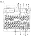
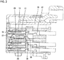
- the first housing 10 is made of synthetic resin and the entirety has a block-like shape as shown in Figs. 1 and 2 .
- the first housing 10 includes therein a plurality of elongate terminal storage rooms 11 extending in the front-and-rear direction that are arranged in the upper-and-lower direction and the left-and-right direction.
- Each terminal storage room 11 is inserted with a female terminal fitting 12 (the terminal fitting according to claims) including a square tube section 13 at a front end section.
- the terminal storage rooms 11 adjacent to each other at the uppermost stage in the left-and-right direction are assumed as a pair.
- one terminal storage space 14 is provided at the lower side of each pair of two terminal storage rooms 11.
- a pair of terminal storage rooms 11 has the lower face of the front end section communicating with the upper face of the terminal storage space 14.
- the front face of the first housing 10 has a plurality of tab insertion openings 15 individually communicating with the front end of each the terminal storage room 11.
- the tab insertion opening 15 is an opening through which a tab 34 of a male terminal fitting 33 provided in the second housing 30 (which will be described later) is inserted into the terminal storage room 11.
- the tab insertion opening 15 has an opening having a substantially-square shape.
- the front face of the first housing 10 has the opening edge of the tab insertion opening 15 having a guiding inclined plane 16 provided over the entire periphery.
- the front face of the first housing 10 has a cancellation insertion inlet 17 opened to communicate with the upper end of the terminal storage space 14.
- the cancellation insertion inlet 17 is composed of a first opening 18 and a second opening 19.
- the first opening 18 has a slit-like shape elongating in the left-and-right direction.
- the first opening 18 is formed in the left-and-right direction within a region corresponding to a pair of the terminal storage rooms 11 (two tab insertion openings 15) provided at the upper side of the terminal storage space 14.
- the second opening 19 is provided at the lower side of the first opening 18 and communicates with the center of the first opening 18 in the left-and-right direction.
- a region of the opening edge of the first opening 18 except for the opening upper edge 20 includes a guide face 21 obtained by tapering and concaving the front face of the first housing 10.
- the opening edge of the second opening 19 also has the guide face 21.
- the opening upper edge 20 of the first opening 18 is close to the guiding inclined plane 16 of the tab insertion opening 15, the opening upper edge 20 does not have the guide face 21 on the front face of the first housing 10, thus the front face of the first housing 10 has a substantially right angle to the inner face of the first opening 18.
- the inner face of the cancellation insertion inlet 17 at the opening upper edge 20 and the upper face of the terminal storage space 14 are continuously flush at the same height.
- Each terminal storage space 14 stores therein a short terminal 22.
- the short terminal 22 is a single piece that includes a base portion 23 to fix the short terminal 22 while being positioned in the terminal storage space 14 and a pair of left and right elastic contact pieces 24 provided at the upper side of the base portion 23.
- the elastic contact pieces 24 can be elastically deformed in the up-and-down direction. When the pair of elastic contact pieces 24 has an elastic contact with the lower face of the square tube section 13 of the pair of female terminal fittings 12 provided at the upper side thereof, this pair of female terminal fittings 12 is turned into a short-circuit state.
- the second housing 30 is made of synthetic resin and includes, as shown in Fig. 3 , a terminal retention portion 31 and a hood portion 32 having a square tube-like shape protruding from the outer periphery of the terminal retention portion 31 to the front side.
- the hood portion 32 includes therein tabs 34 at the tip ends of a plurality of the male terminal fittings 33 attached to the terminal retention portion 31.
- the hood portion 32 includes therein a plurality of short-cancelling projections 35 corresponding to the respective cancellation insertion inlets 17 of the first housing 10.
- Each short-cancelling projection 35 is protruded in a cantilevered manner from the front end face of the terminal retention portion 31 (the deep-side end face of the hood portion 32) to the front side and is integrated with the terminal retention portion 31.
- the short-cancelling projection 35 is protruded in the same direction as a direction along which the second housing 30 is mated with the first housing 10.
- the short-cancelling projection 35 includes a support portion 36 and a pair of plate-shaped insulating portions 37 that are symmetric in the left-and-right direction.
- the support portion 36 has an elongated shape extending in the front-and-rear direction. When being seen from a direct light viewing angle, the support portion 36 has a substantially-square shape as shown in Fig. 7 for which the height is slightly larger than the width.
- a region of the support portion 36 except for the front end section (tip end) has an upper face forming a horizontal surface parallel to the direction along which both of the housings 10 and 30 are mated.
- the lower face of the support portion 36 has a substantially arc shape when seen from a direct light viewing angle. Both of the left and right side faces of the support portion 36 are a plane parallel to the direction along which both of the housings 10 and 30 are mated.
- a pair of plate-shaped insulating portions 37 has a plate-like shape protruding from the upper end of the support portion 36 to both sides in the left-and-right direction in a horizontal and cantilever-like manner. Specifically, a region at the lower end side of the support portion 36 has a rib-like shape that protrudes from the lower faces of both of the plate-shaped insulating portions 37. This rib-like protrusion part of the support portion 36 has a function to improve the bending rigidity of the plate-shaped insulating portion 37 in the up-and-down direction (the plate thickness direction of the plate-shaped insulating portion 37).
- the plate-shaped insulating portion 37 is formed in a region in the front-and-rear direction that extends from the front face of the terminal retention portion 31 to a position at a slightly-rear side of the front end of the support portion 36.
- a major part of the upper face of the plate-shaped insulating portion 37 except for the front end edge has a horizontal surface that is continuously flush to the upper face of the support portion 36.
- the connector of this embodiment is used for an airbag circuit for an automobile.
- the pair of elastic contact pieces 24 is elastically abutted to the lower face of the square tube section 13 of the pair of female terminal fittings 12 to thereby allow the short terminal 22 to retain the pair of female terminal fittings 12 in a short-circuit state. This consequently prevents the airbag from erroneously inflating.
- the short circuiting of the pair of female terminal fittings 12 is cancelled so that the airbag is normally operable.
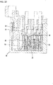
- the short-cancelling projection 35 enters the terminal storage space 14 from the cancellation insertion inlet 17. Then, the pair of plate-shaped insulating portions 37 passes the first opening 18 and the support portion 36 passes the second opening 19. Then, as shown in Fig. 13 , the support portion 36 is placed between the pair of elastic contact pieces 24 so as to partition both of the elastic contact pieces 24.
- the support portion 36 corresponds to a partition wall 25 that partitions the pair of terminal storage rooms 11 provided in the left-and-right direction and is provided in vicinity below the lower side of this partition wall 25.
- the pair of plate-shaped insulating portions 37 is abutted to the pair of elastic contact pieces 24 to separate both of the elastic contact pieces 24 from the female terminal fitting 12, thereby cancelling the short circuiting of the pair of female terminal fittings 12.
- the plate-shaped insulating portion 37 is placed between the elastic contact pieces 24 and the female terminal fitting 12, while there is a gap between the upper face of the plate-shaped insulating portion 37 and the lower face of the female terminal fitting 12.
- This gap is provided for the purpose of preventing the plate-shaped insulating portion 37 from interfering with the terminal fitting in a process of mating the housings 10 and 30.
- This gap is obtained by setting the height of the upper face of the plate-shaped insulating portion 37 to be lower than the height of the lower face of the female terminal fitting 12.
- the plate-shaped insulating portion 37 always receives an elastic depression force (biasing force) upward (in the plate thickness direction of plate-shaped insulating portion 37) caused by the elastic restoring force by the elastic contact piece 24 from below.
- This deformation causes, as shown in Fig. 4 , the entire short-cancelling projection 35 to be upwardly raised while the rear end (an end supported by the front face of the terminal retention portion 31) acts as a pivot point.
- the short-cancelling projection 35 is upwardly displaced in the maximum amount at the front end section of the short-cancelling projection 35 (or a tip end in the protrusion direction).
- the plate-shaped insulating portion 37 is upwardly raised while a base end continuous from the support portion 36 acts as a pivot point. Then, the plate-shaped insulating portion 37 is upwardly displaced in the maximum amount at the outer edge of the free end side of the plate-shaped insulating portion 37 in the left-and-right direction (an opposite side of the support portion 36).
- the abnormal deformation as described above is maintained even when both of the housings 10 and 30 are separated for maintenance for example. This causes, when the housings 10 and 30 are tried to be mated again after the maintenance for example, the short-cancelling projection 35 to be abutted to the front face of the first housing 10. The short-cancelling projection 35 abutted to the front face of the first housing 10 prevents both of the housings 10 and 30 from being mated.
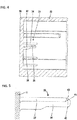
- the short-cancelling projection 35 has the first to third correction portions 41, 42, and 43 as shown in Figs. 5 and 6 as a means to correct the deformation of the short-cancelling projection 35 to provide the entry to the cancellation insertion inlet 17.
- the first correction portion 41 (the first correction portion in claims) is formed at the front end section of the upper face of the support portion 36 (a tip end in the protrusion direction).
- the first correction portion 41 is inclined to lower the height while extending toward the tip end of the protrusion of the short-cancelling projection 35.
- a pitch of this first correction portion 41 is an angle configured to, in the up-and-down direction (a direction substantially parallel to the direction along which the elastic contact piece 24 depresses the female terminal fitting 12), approach the short terminal 22 while extending toward the tip end of the protrusion of the short-cancelling projection 35.
- a region in the protrusion direction of the short-cancelling projection 35 in which the first correction portion 41 is formed extends from the front tip end (protrusion end) of the support portion 36 to a position at a slightly rear side of the front end of the plate-shaped insulating portion 37.
- the second correction portion 42 (the second correction portion in the claims) is formed at the front end edge of the pair of plate-shaped insulating portions 37.
- the second correction portion 42 is formed to continue over the entire width in the left-and-right direction of the plate-shaped insulating portion 37.
- the second correction portion 42 is inclined backward in the protrusion direction of the short-cancelling projection 35 while extending away from the support portion 36.
- the second correction portion 42 has the foremost tip end.
- the foremost tip end of the second correction portion 42 is at a position slightly rear side of the front end of the support portion 36 and the front end of the first correction portion 41 and slightly front side of the rear end of the first correction portion 41.
- the third correction portion 43 (the third correction portion in the claims) is continuously formed over the entire width region of the protrusion end edge (front end edge) of the pair of plate-shaped insulating portions 37 extending in the left-and-right direction. Similarly to the first correction portion 41, the third correction portion 43 is inclined to lower the height while extending toward the tip end of the protrusion of the short-cancelling projection 35. The base end of the third correction portion 43 (an end closer to the support portion 36 in the left-and-right direction) is smoothly continuous to the first correction portion 41. Similarly to the second correction portion 42, the third correction portion 43 is continuously formed over the entire width region of the plate-shaped insulating portion 37. Thus, the foremost tip end of the third correction portion 43 is at a position slightly rear side of the front end of the support portion 36 and the front end of the first correction portion 41 and slightly front side of the rear end of the first correction portion 41.
- the protrusion end (front end) of the short-cancelling projection 35 has a sliding contact with the opening upper edge 20 of the front face of the first housing 10 in which the guide face 21 is not formed.
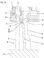
- the front face of the first housing 10 is firstly abutted only to the first correction portion 41 of the support portion 36 of the short-cancelling projection 35.
- the first correction portion 41 is downwardly inclined with respect to the direction along which both of the housings 10 and 30 are mated, when both of the housings 10 and 30 are further mated, the inclination of the first correction portion 41 downwardly corrects the entire posture of the short-cancelling projection 35.
- the entire support portion 36 is inserted into the first opening 18.
- a base end of the second correction portion 42 and the third correction portion 43 that is closer to the support portion 36 subsequently has a sliding contact with the opening upper edge 20.
- the plate-shaped insulating portion 37 is upwardly deformed so that the free end side has the maximum displacement amount.
- the second correction portion 42 is inclined so that the free end side is retracted.
- the second correction portion 42 and the third correction portion 43 have a sliding contact with the opening upper edge 20 (the first housing 10) at a position that gradually moves to the free end side with the increase of the mating of both of the housings 10 and 30.
- the short-cancelling projection 35 is placed between the elastic contact piece 24 and the female terminal fitting 12 while being upwardly deformed.
- the short-cancelling projection 35 is deformed in an amount smaller than that when both of the housings 10 and 30 are separated. Even when the short-cancelling projection 35 is deformed, the elastic contact piece 24 is downwardly depressed by the plate-shaped insulating portion 37 and is separated from the female terminal fitting 12, thus maintaining the pair of female terminal fittings 12 in a short-cancelling state.
- the connector of this embodiment includes the first housing 10 in which the pair of female terminal fittings 12 are stored laterally, the second housing 30 that can be mated with and separated from the first housing 10, and the short terminal 22 provided in the first housing 10.
- the short terminal 22 is configured, when both of the housings 10 and 30 are separated, to bring the pair of elastic contact pieces 24 elastically contact with the pair of female terminal fittings 12 to thereby cause the pair of female terminal fittings 12 to be short-circuited.
- the second housing 30 has the short-cancelling projection 35 protruding in the same direction as the direction along which the second housing 30 is mated with the first housing 10.
- the support portion 36 constituting the short-cancelling projection 35 is provided so as to partition a pair of elastic contact pieces 24 while both of the housings 10 and 30 being mated.
- the pair of plate-shaped insulating portions 37 which similarly constitutes the short-cancelling projection 35 as in the support portion 36, is provided to protrude from the support portion 36 in directions opposite to each other in the left-and-right direction.
- the pair of plate-shaped insulating portions 37 is placed between the pair of elastic contact pieces 24 and the pair of female terminal fittings 12 while both of the housings 10 and 30 being mated, thereby cancelling the short circuiting of the female terminal fitting 12.
- the protruding end of the support portion 36 and the protruding end of the pair of plate-shaped insulating portions 37 have the first to third correction portions 41, 42, and 43.
- These correction portions 41, 42, and 43 are configured, in a process of mating both of the housings 10 and 30, to be abutted to (or to correct) the front face of the first housing 10 to thereby displace the short-cancelling projection 35 in a direction toward the short terminal 22.
- the first to third correction portions 41, 42, and 43 are abutted to the first housing 10 to thereby displace the short-cancelling projection 35 to approach the short terminal 22. This can consequently prevent the short-cancelling projection 35 from being abutted to the first housing 10, thus allowing both of the housings 10 and 30 to be mated smoothly.
- the protruding end of the support portion 36 has the first correction portion 41 downwardly inclined to approach the short terminal 22 while extending toward the tip end of the protrusion of the short-cancelling projection 35.
- the support portion 36 is provided so as to partition a pair of elastic contact pieces 24, thus allowing the support portion 36 to have a large size in the direction along which the terminal fitting is depressed by the elastic contact piece 24 (up-and-down direction). This can consequently provide a large range within which the correction by the first correction portion 41 can be performed (i.e., a range within which the first housing 10 has a sliding contact with the opening upper edge 20).
- the tip end (front end) of the first correction portion 41 is provided at the tip end (or the front side) of the protruding end of the plate-shaped insulating portion 37. This configuration allows, in a process of mating both of the housings 10 and 30, the first correction portion 41 to sufficiently correct the inclined shape of the short-cancelling projection 35 prior to the abutment of the plate-shaped insulating portion 37 to the first housing 10.
- the plate-shaped insulating portion 37 is displaced by the depression from the elastic contact piece 24 in the plate thickness direction (or in an upward direction) in a displacement amount that increases toward the free end side far from the support portion 36.
- the protruding end of the pair of plate-shaped insulating portions 37 has the second correction portion 42 that is inclined backward in the protrusion direction of the short-cancelling projection 35 while extending away from the support portion 36.
- This inclination allows, in a process of mating both of the housings 10 and 30, the second correction portion 42 to be preferentially abutted to a region closer to the support portion 36 having a relatively-small displacement amount. This can consequently prevent the plate-shaped insulating portion 37 from being abutted to the first housing 10, thus securing allowing both of the housings 10 and 30 to be mated.
- the protruding end of plate-shaped insulating portion 37 has the third correction portion 43 inclined to approach the short terminal 22 while extending toward the tip end of the protrusion of the short-cancelling projection 35.
- This configuration allows, after the correction of the short-cancelling projection 35 by the first correction portion 41, the third correction portion 43 to correct the short-cancelling projection 35.
- the third correction portion 43 smoothly continued to the first correction portion 41 can provide the correction operation by the first correction portion 41 and the correction operation by the third correction portion 43 in a continuous manner without being interfered for example.
Landscapes
- Details Of Connecting Devices For Male And Female Coupling (AREA)
Claims (3)
- Verbinder, umfassend:ein erstes Gehäuse (10), das so ausgestaltet ist, dass darin ein Paar von Anschlussstücken (12) aufgenommen sind, die auf eine seitliche Weise angeordnet sind;ein zweites Gehäuse (30), das in der Lage ist, mit dem ersten Gehäuse (10) gepaart und davon getrennt zu werden;einen Kurzschlussanschluss (22), der in dem ersten Gehäuse (10) bereitgestellt ist, wobei der Kurzschlussanschluss (22) so ausgestaltet ist, dass er, wenn das erste Gehäuse (10) von dem zweiten Gehäuse (30) getrennt wird, ein Paar von elastischen Kontaktstücken (24) elastisch mit dem Paar von Anschlussstücken (12) in Kontakt bringt, wodurch das Kurzschließen des Paares von Anschlussstücken (12) bewirkt wird;einen Kurzschluss-Aufhebungsvorsprung (35), der in dem zweiten Gehäuse (30) gebildet ist, wobei der Kurzschluss-Aufhebungsvorsprung (35) in die gleiche Richtung wie die Richtung hervorsteht, entlang der das zweite Gehäuse (30) mit dem ersten Gehäuse (10) in Eingriff gebracht wird;einen Stützabschnitt (36), der den Kurzschluss-Aufhebungsvorsprung (35) bildet, wobei der Stützabschnitt (36) so ausgestaltet ist, dass er, wenn das erste Gehäuse (10) mit dem zweiten Gehäuse (30) gepaart wird, das Paar von elastischen Kontaktstücken (24) trennt;ein Paar von plattenförmigen Isolationsabschnitten (37), die von dem Stützabschnitt (36) in einander entgegengesetzten Richtungen hervorstehen, wobei die plattenförmigen Isolationsabschnitte (37) den Kurzschluss-Aufhebungsvorsprung (35) bilden und so ausgestaltet sind, dass sie in einem Zustand, in dem das erste Gehäuse (10) mit dem zweiten Gehäuse (30) in Eingriff gebracht wird, so zwischen dem Paar von elastischen Kontaktstücken (24) und dem Paar von Anschlussstücken (12) platziert werden, dass das Kurzschließen des Paares von Anschlusstücken (12) aufgehoben wird; undeinen Korrekturabschnitt (41, 42, 43), der an mindestens einem eines hervorstehenden Endes des Stützabschnitts (36) und eines hervorstehenden Endes des plattenförmigen Isolationsabschnitts (37) gebildet ist, wobei der Korrekturabschnitt (41, 42, 43) ausgestaltet ist, dass er so an das erste Gehäuse (10) anstößt, dass der Kurzschluss-Aufhebungsvorsprung (35) in einer Richtung verlagert wird, entlang der der Kurzschluss-Aufhebungsvorsprung (35) sich an den Kurzschlussanschluss (22) annähert,wobeidas hervorstehende Ende des Stützabschnitts (36) einen ersten Korrekturabschnitt (41) aufweist, der so geneigt ist, dass er sich an den Kurzschlussanschluss (22) annähert, während er sich hin zu einem Spitzenende in einer Richtung des Hervorstehens des Kurzschluss-Aufhebungsvorsprungs (35) erstreckt, unddas hervorstehende Ende des plattenförmigen Isolationsabschnitts (37) einen dritten Korrekturabschnitt (43) aufweist, der so geneigt ist, dass er sich an den Kurzschlussanschluss (22) annähert, während er sich hin zu dem Spitzenende in der Richtung des Hervorstehens des Kurzschluss-Aufhebungsvorsprungs (35) erstreckt,dadurch gekennzeichnet, dassdas Paar von plattenförmigen Isolationsabschnitten (37) ein hervorstehendes Ende aufweisen, das einen zweiten Korrekturabschnitt (42) aufweist, der in der Richtung des Hervorstehens des Kurzschluss-Aufhebungsvorsprungs (35) nach hinten geneigt ist, während er sich von dem Stützabschnitt (36) weg erstreckt.
- Verbinder nach Anspruch 1, wobei das Spitzenende des ersten Korrekturabschnitts (41) jenseits des hervorstehenden Endes des plattenförmigen Isolationsabschnitts (37) in der Richtung des Hervorstehens bereitgestellt ist.
- Verbinder nach Anspruch 1 oder 2, wobei der dritte Korrekturabschnitt (43) nahtlos mit dem ersten Korrekturabschnitt (41) zusammenhängt.
Applications Claiming Priority (2)
| Application Number | Priority Date | Filing Date | Title |
|---|---|---|---|
| JP2015249342A JP6540499B2 (ja) | 2015-12-22 | 2015-12-22 | コネクタ |
| PCT/JP2016/088307 WO2017110983A1 (ja) | 2015-12-22 | 2016-12-22 | コネクタ |
Publications (3)
| Publication Number | Publication Date |
|---|---|
| EP3396792A1 EP3396792A1 (de) | 2018-10-31 |
| EP3396792A4 EP3396792A4 (de) | 2018-12-19 |
| EP3396792B1 true EP3396792B1 (de) | 2021-02-24 |
Family
ID=59089524
Family Applications (1)
| Application Number | Title | Priority Date | Filing Date |
|---|---|---|---|
| EP16878870.1A Active EP3396792B1 (de) | 2015-12-22 | 2016-12-22 | Verbinder |
Country Status (5)
| Country | Link |
|---|---|
| US (1) | US10476206B2 (de) |
| EP (1) | EP3396792B1 (de) |
| JP (1) | JP6540499B2 (de) |
| CN (1) | CN108370123B (de) |
| WO (1) | WO2017110983A1 (de) |
Families Citing this family (3)
| Publication number | Priority date | Publication date | Assignee | Title |
|---|---|---|---|---|
| JP6840640B2 (ja) * | 2017-08-18 | 2021-03-10 | 日本航空電子工業株式会社 | コネクタ装置 |
| JP7140010B2 (ja) * | 2019-03-14 | 2022-09-21 | 株式会社オートネットワーク技術研究所 | 雄コネクタ、およびコネクタ |
| CN112018540A (zh) * | 2020-07-21 | 2020-12-01 | 郑州森源新能源科技有限公司 | 一种电流互感器二次侧防开路用连接器 |
Family Cites Families (19)
| Publication number | Priority date | Publication date | Assignee | Title |
|---|---|---|---|---|
| US5263872A (en) * | 1992-12-22 | 1993-11-23 | The Whitaker Corporation | Electrical shorting system |
| JP3090000B2 (ja) * | 1995-08-08 | 2000-09-18 | 住友電装株式会社 | コネクタ |
| EP0758806B1 (de) * | 1995-08-08 | 2000-01-19 | Sumitomo Wiring Systems, Ltd. | Elektrischer Verbinder |
| JP3073697B2 (ja) * | 1996-08-21 | 2000-08-07 | 住友電装株式会社 | コネクタに対するショート端子の取付け構造及び取付け方法 |
| US5788520A (en) * | 1997-01-07 | 1998-08-04 | Osram Sylvania Inc. | Connector shorting bar retention |
| JP3314862B2 (ja) * | 1997-02-05 | 2002-08-19 | 住友電装株式会社 | ロック検知コネクタ |
| JP2001511299A (ja) * | 1997-02-11 | 2001-08-07 | ザ ウィタカー コーポレーション | シャント付き電気コネクタ |
| JP3374735B2 (ja) * | 1997-12-12 | 2003-02-10 | 住友電装株式会社 | コネクタ |
| EP1220360B1 (de) * | 2000-12-28 | 2006-06-21 | Sumitomo Wiring Systems, Ltd. | Leiterplattenrandverbinder |
| JP2002260790A (ja) | 2001-03-06 | 2002-09-13 | Sumitomo Wiring Syst Ltd | コネクタ |
| JP4042674B2 (ja) * | 2003-10-01 | 2008-02-06 | 住友電装株式会社 | コネクタ |
| JP2008027760A (ja) * | 2006-07-21 | 2008-02-07 | Sumitomo Wiring Syst Ltd | 嵌合検知機能を備えたコネクタ |
| JP2008097908A (ja) | 2006-10-10 | 2008-04-24 | Sumitomo Wiring Syst Ltd | コネクタ |
| JP4876985B2 (ja) * | 2007-03-09 | 2012-02-15 | 住友電装株式会社 | コネクタ |
| EP1986284B1 (de) | 2007-04-23 | 2014-08-20 | Sumitomo Wiring Systems, Ltd. | Steckverbinder und Montageverfahren dafür |
| JP4985206B2 (ja) * | 2007-04-23 | 2012-07-25 | 住友電装株式会社 | コネクタ及びショート端子 |
| US7955104B1 (en) * | 2010-03-08 | 2011-06-07 | Delphi Technologies, Inc. | Shorting clip terminal connector assembly including protrusion shield |
| JP2012134006A (ja) * | 2010-12-21 | 2012-07-12 | Yazaki Corp | コネクタ |
| JP5534350B2 (ja) * | 2011-02-16 | 2014-06-25 | 住友電装株式会社 | コネクタ装置 |
-
2015
- 2015-12-22 JP JP2015249342A patent/JP6540499B2/ja active Active
-
2016
- 2016-12-22 WO PCT/JP2016/088307 patent/WO2017110983A1/ja not_active Ceased
- 2016-12-22 EP EP16878870.1A patent/EP3396792B1/de active Active
- 2016-12-22 US US16/063,482 patent/US10476206B2/en active Active
- 2016-12-22 CN CN201680074594.8A patent/CN108370123B/zh active Active
Non-Patent Citations (1)
| Title |
|---|
| None * |
Also Published As
| Publication number | Publication date |
|---|---|
| US10476206B2 (en) | 2019-11-12 |
| CN108370123A (zh) | 2018-08-03 |
| JP2017117553A (ja) | 2017-06-29 |
| EP3396792A1 (de) | 2018-10-31 |
| US20180375259A1 (en) | 2018-12-27 |
| JP6540499B2 (ja) | 2019-07-10 |
| WO2017110983A1 (ja) | 2017-06-29 |
| EP3396792A4 (de) | 2018-12-19 |
| CN108370123B (zh) | 2020-03-13 |
Similar Documents
| Publication | Publication Date | Title |
|---|---|---|
| US10566725B2 (en) | Connector with laterally mounted retainer for supporting and locking a terminal fitting | |
| JP5708837B1 (ja) | コネクタ端子 | |
| US9515396B2 (en) | Female terminal fitting | |
| JP2018139209A (ja) | 端子位置保証装置を有する電気コネクタ | |
| JP4985206B2 (ja) | コネクタ及びショート端子 | |
| CN109524818B (zh) | 连接器 | |
| EP3396792B1 (de) | Verbinder | |
| CN105210239A (zh) | 阴端子接头 | |
| JP5999510B2 (ja) | 雌端子金具及びその製造方法 | |
| US8784133B2 (en) | Connector | |
| CN112531385B (zh) | 连接器及端子零件 | |
| US11217925B2 (en) | Female terminal | |
| US9722341B2 (en) | Connector with streamline locking lances | |
| JP2010040183A (ja) | コネクタ | |
| US20200212617A1 (en) | Connector | |
| US20160172779A1 (en) | Connector | |
| US11349242B2 (en) | Male wire terminal and male wire connector | |
| US9356375B2 (en) | Male terminal fitting | |
| US11158986B2 (en) | Shorting terminal and connector | |
| US10050388B2 (en) | Connector having a shorting terminal with a pair of press-fit projections | |
| JP2014229463A (ja) | コネクタ | |
| KR20160086285A (ko) | 커넥터 | |
| JP2019096535A (ja) | コネクタ | |
| CN103229366A (zh) | 电子装置的连接结构 | |
| US20210159617A1 (en) | Contact and Connector |
Legal Events
| Date | Code | Title | Description |
|---|---|---|---|
| STAA | Information on the status of an ep patent application or granted ep patent |
Free format text: STATUS: THE INTERNATIONAL PUBLICATION HAS BEEN MADE |
|
| PUAI | Public reference made under article 153(3) epc to a published international application that has entered the european phase |
Free format text: ORIGINAL CODE: 0009012 |
|
| STAA | Information on the status of an ep patent application or granted ep patent |
Free format text: STATUS: REQUEST FOR EXAMINATION WAS MADE |
|
| 17P | Request for examination filed |
Effective date: 20180614 |
|
| AK | Designated contracting states |
Kind code of ref document: A1 Designated state(s): AL AT BE BG CH CY CZ DE DK EE ES FI FR GB GR HR HU IE IS IT LI LT LU LV MC MK MT NL NO PL PT RO RS SE SI SK SM TR |
|
| AX | Request for extension of the european patent |
Extension state: BA ME |
|
| REG | Reference to a national code |
Ref country code: DE Ref legal event code: R079 Ref document number: 602016053358 Country of ref document: DE Free format text: PREVIOUS MAIN CLASS: H01R0013710000 Ipc: H01R0013703000 |
|
| RIC1 | Information provided on ipc code assigned before grant |
Ipc: H01R 13/436 20060101ALN20181108BHEP Ipc: H01R 107/00 20060101ALN20181108BHEP Ipc: H01R 13/703 20060101AFI20181108BHEP |
|
| A4 | Supplementary search report drawn up and despatched |
Effective date: 20181115 |
|
| DAV | Request for validation of the european patent (deleted) | ||
| DAX | Request for extension of the european patent (deleted) | ||
| STAA | Information on the status of an ep patent application or granted ep patent |
Free format text: STATUS: EXAMINATION IS IN PROGRESS |
|
| 17Q | First examination report despatched |
Effective date: 20200722 |
|
| GRAP | Despatch of communication of intention to grant a patent |
Free format text: ORIGINAL CODE: EPIDOSNIGR1 |
|
| STAA | Information on the status of an ep patent application or granted ep patent |
Free format text: STATUS: GRANT OF PATENT IS INTENDED |
|
| INTG | Intention to grant announced |
Effective date: 20201120 |
|
| GRAS | Grant fee paid |
Free format text: ORIGINAL CODE: EPIDOSNIGR3 |
|
| GRAA | (expected) grant |
Free format text: ORIGINAL CODE: 0009210 |
|
| STAA | Information on the status of an ep patent application or granted ep patent |
Free format text: STATUS: THE PATENT HAS BEEN GRANTED |
|
| AK | Designated contracting states |
Kind code of ref document: B1 Designated state(s): AL AT BE BG CH CY CZ DE DK EE ES FI FR GB GR HR HU IE IS IT LI LT LU LV MC MK MT NL NO PL PT RO RS SE SI SK SM TR |
|
| REG | Reference to a national code |
Ref country code: CH Ref legal event code: EP |
|
| REG | Reference to a national code |
Ref country code: AT Ref legal event code: REF Ref document number: 1365667 Country of ref document: AT Kind code of ref document: T Effective date: 20210315 |
|
| REG | Reference to a national code |
Ref country code: IE Ref legal event code: FG4D |
|
| REG | Reference to a national code |
Ref country code: DE Ref legal event code: R096 Ref document number: 602016053358 Country of ref document: DE |
|
| REG | Reference to a national code |
Ref country code: LT Ref legal event code: MG9D |
|
| REG | Reference to a national code |
Ref country code: NL Ref legal event code: MP Effective date: 20210224 |
|
| PG25 | Lapsed in a contracting state [announced via postgrant information from national office to epo] |
Ref country code: BG Free format text: LAPSE BECAUSE OF FAILURE TO SUBMIT A TRANSLATION OF THE DESCRIPTION OR TO PAY THE FEE WITHIN THE PRESCRIBED TIME-LIMIT Effective date: 20210524 Ref country code: LT Free format text: LAPSE BECAUSE OF FAILURE TO SUBMIT A TRANSLATION OF THE DESCRIPTION OR TO PAY THE FEE WITHIN THE PRESCRIBED TIME-LIMIT Effective date: 20210224 Ref country code: PT Free format text: LAPSE BECAUSE OF FAILURE TO SUBMIT A TRANSLATION OF THE DESCRIPTION OR TO PAY THE FEE WITHIN THE PRESCRIBED TIME-LIMIT Effective date: 20210624 Ref country code: NO Free format text: LAPSE BECAUSE OF FAILURE TO SUBMIT A TRANSLATION OF THE DESCRIPTION OR TO PAY THE FEE WITHIN THE PRESCRIBED TIME-LIMIT Effective date: 20210524 Ref country code: GR Free format text: LAPSE BECAUSE OF FAILURE TO SUBMIT A TRANSLATION OF THE DESCRIPTION OR TO PAY THE FEE WITHIN THE PRESCRIBED TIME-LIMIT Effective date: 20210525 Ref country code: FI Free format text: LAPSE BECAUSE OF FAILURE TO SUBMIT A TRANSLATION OF THE DESCRIPTION OR TO PAY THE FEE WITHIN THE PRESCRIBED TIME-LIMIT Effective date: 20210224 Ref country code: HR Free format text: LAPSE BECAUSE OF FAILURE TO SUBMIT A TRANSLATION OF THE DESCRIPTION OR TO PAY THE FEE WITHIN THE PRESCRIBED TIME-LIMIT Effective date: 20210224 |
|
| REG | Reference to a national code |
Ref country code: AT Ref legal event code: MK05 Ref document number: 1365667 Country of ref document: AT Kind code of ref document: T Effective date: 20210224 |
|
| PG25 | Lapsed in a contracting state [announced via postgrant information from national office to epo] |
Ref country code: SE Free format text: LAPSE BECAUSE OF FAILURE TO SUBMIT A TRANSLATION OF THE DESCRIPTION OR TO PAY THE FEE WITHIN THE PRESCRIBED TIME-LIMIT Effective date: 20210224 Ref country code: PL Free format text: LAPSE BECAUSE OF FAILURE TO SUBMIT A TRANSLATION OF THE DESCRIPTION OR TO PAY THE FEE WITHIN THE PRESCRIBED TIME-LIMIT Effective date: 20210224 Ref country code: LV Free format text: LAPSE BECAUSE OF FAILURE TO SUBMIT A TRANSLATION OF THE DESCRIPTION OR TO PAY THE FEE WITHIN THE PRESCRIBED TIME-LIMIT Effective date: 20210224 Ref country code: RS Free format text: LAPSE BECAUSE OF FAILURE TO SUBMIT A TRANSLATION OF THE DESCRIPTION OR TO PAY THE FEE WITHIN THE PRESCRIBED TIME-LIMIT Effective date: 20210224 Ref country code: NL Free format text: LAPSE BECAUSE OF FAILURE TO SUBMIT A TRANSLATION OF THE DESCRIPTION OR TO PAY THE FEE WITHIN THE PRESCRIBED TIME-LIMIT Effective date: 20210224 |
|
| PG25 | Lapsed in a contracting state [announced via postgrant information from national office to epo] |
Ref country code: IS Free format text: LAPSE BECAUSE OF FAILURE TO SUBMIT A TRANSLATION OF THE DESCRIPTION OR TO PAY THE FEE WITHIN THE PRESCRIBED TIME-LIMIT Effective date: 20210624 |
|
| PG25 | Lapsed in a contracting state [announced via postgrant information from national office to epo] |
Ref country code: SM Free format text: LAPSE BECAUSE OF FAILURE TO SUBMIT A TRANSLATION OF THE DESCRIPTION OR TO PAY THE FEE WITHIN THE PRESCRIBED TIME-LIMIT Effective date: 20210224 Ref country code: AT Free format text: LAPSE BECAUSE OF FAILURE TO SUBMIT A TRANSLATION OF THE DESCRIPTION OR TO PAY THE FEE WITHIN THE PRESCRIBED TIME-LIMIT Effective date: 20210224 Ref country code: EE Free format text: LAPSE BECAUSE OF FAILURE TO SUBMIT A TRANSLATION OF THE DESCRIPTION OR TO PAY THE FEE WITHIN THE PRESCRIBED TIME-LIMIT Effective date: 20210224 Ref country code: CZ Free format text: LAPSE BECAUSE OF FAILURE TO SUBMIT A TRANSLATION OF THE DESCRIPTION OR TO PAY THE FEE WITHIN THE PRESCRIBED TIME-LIMIT Effective date: 20210224 |
|
| REG | Reference to a national code |
Ref country code: DE Ref legal event code: R097 Ref document number: 602016053358 Country of ref document: DE |
|
| PG25 | Lapsed in a contracting state [announced via postgrant information from national office to epo] |
Ref country code: SK Free format text: LAPSE BECAUSE OF FAILURE TO SUBMIT A TRANSLATION OF THE DESCRIPTION OR TO PAY THE FEE WITHIN THE PRESCRIBED TIME-LIMIT Effective date: 20210224 Ref country code: RO Free format text: LAPSE BECAUSE OF FAILURE TO SUBMIT A TRANSLATION OF THE DESCRIPTION OR TO PAY THE FEE WITHIN THE PRESCRIBED TIME-LIMIT Effective date: 20210224 Ref country code: DK Free format text: LAPSE BECAUSE OF FAILURE TO SUBMIT A TRANSLATION OF THE DESCRIPTION OR TO PAY THE FEE WITHIN THE PRESCRIBED TIME-LIMIT Effective date: 20210224 |
|
| PLBE | No opposition filed within time limit |
Free format text: ORIGINAL CODE: 0009261 |
|
| STAA | Information on the status of an ep patent application or granted ep patent |
Free format text: STATUS: NO OPPOSITION FILED WITHIN TIME LIMIT |
|
| PG25 | Lapsed in a contracting state [announced via postgrant information from national office to epo] |
Ref country code: AL Free format text: LAPSE BECAUSE OF FAILURE TO SUBMIT A TRANSLATION OF THE DESCRIPTION OR TO PAY THE FEE WITHIN THE PRESCRIBED TIME-LIMIT Effective date: 20210224 Ref country code: ES Free format text: LAPSE BECAUSE OF FAILURE TO SUBMIT A TRANSLATION OF THE DESCRIPTION OR TO PAY THE FEE WITHIN THE PRESCRIBED TIME-LIMIT Effective date: 20210224 |
|
| 26N | No opposition filed |
Effective date: 20211125 |
|
| PG25 | Lapsed in a contracting state [announced via postgrant information from national office to epo] |
Ref country code: SI Free format text: LAPSE BECAUSE OF FAILURE TO SUBMIT A TRANSLATION OF THE DESCRIPTION OR TO PAY THE FEE WITHIN THE PRESCRIBED TIME-LIMIT Effective date: 20210224 |
|
| PG25 | Lapsed in a contracting state [announced via postgrant information from national office to epo] |
Ref country code: IT Free format text: LAPSE BECAUSE OF FAILURE TO SUBMIT A TRANSLATION OF THE DESCRIPTION OR TO PAY THE FEE WITHIN THE PRESCRIBED TIME-LIMIT Effective date: 20210224 |
|
| PG25 | Lapsed in a contracting state [announced via postgrant information from national office to epo] |
Ref country code: IS Free format text: LAPSE BECAUSE OF FAILURE TO SUBMIT A TRANSLATION OF THE DESCRIPTION OR TO PAY THE FEE WITHIN THE PRESCRIBED TIME-LIMIT Effective date: 20210624 |
|
| REG | Reference to a national code |
Ref country code: DE Ref legal event code: R119 Ref document number: 602016053358 Country of ref document: DE |
|
| PG25 | Lapsed in a contracting state [announced via postgrant information from national office to epo] |
Ref country code: MC Free format text: LAPSE BECAUSE OF FAILURE TO SUBMIT A TRANSLATION OF THE DESCRIPTION OR TO PAY THE FEE WITHIN THE PRESCRIBED TIME-LIMIT Effective date: 20210224 |
|
| REG | Reference to a national code |
Ref country code: CH Ref legal event code: PL |
|
| GBPC | Gb: european patent ceased through non-payment of renewal fee |
Effective date: 20211222 |
|
| REG | Reference to a national code |
Ref country code: BE Ref legal event code: MM Effective date: 20211231 |
|
| PG25 | Lapsed in a contracting state [announced via postgrant information from national office to epo] |
Ref country code: LU Free format text: LAPSE BECAUSE OF NON-PAYMENT OF DUE FEES Effective date: 20211222 Ref country code: IE Free format text: LAPSE BECAUSE OF NON-PAYMENT OF DUE FEES Effective date: 20211222 Ref country code: GB Free format text: LAPSE BECAUSE OF NON-PAYMENT OF DUE FEES Effective date: 20211222 Ref country code: DE Free format text: LAPSE BECAUSE OF NON-PAYMENT OF DUE FEES Effective date: 20220701 |
|
| PG25 | Lapsed in a contracting state [announced via postgrant information from national office to epo] |
Ref country code: BE Free format text: LAPSE BECAUSE OF NON-PAYMENT OF DUE FEES Effective date: 20211231 |
|
| PG25 | Lapsed in a contracting state [announced via postgrant information from national office to epo] |
Ref country code: LI Free format text: LAPSE BECAUSE OF NON-PAYMENT OF DUE FEES Effective date: 20211231 Ref country code: CH Free format text: LAPSE BECAUSE OF NON-PAYMENT OF DUE FEES Effective date: 20211231 |
|
| P01 | Opt-out of the competence of the unified patent court (upc) registered |
Effective date: 20230517 |
|
| PG25 | Lapsed in a contracting state [announced via postgrant information from national office to epo] |
Ref country code: CY Free format text: LAPSE BECAUSE OF FAILURE TO SUBMIT A TRANSLATION OF THE DESCRIPTION OR TO PAY THE FEE WITHIN THE PRESCRIBED TIME-LIMIT Effective date: 20210224 |
|
| PG25 | Lapsed in a contracting state [announced via postgrant information from national office to epo] |
Ref country code: HU Free format text: LAPSE BECAUSE OF FAILURE TO SUBMIT A TRANSLATION OF THE DESCRIPTION OR TO PAY THE FEE WITHIN THE PRESCRIBED TIME-LIMIT; INVALID AB INITIO Effective date: 20161222 |
|
| PG25 | Lapsed in a contracting state [announced via postgrant information from national office to epo] |
Ref country code: MK Free format text: LAPSE BECAUSE OF FAILURE TO SUBMIT A TRANSLATION OF THE DESCRIPTION OR TO PAY THE FEE WITHIN THE PRESCRIBED TIME-LIMIT Effective date: 20210224 |
|
| PG25 | Lapsed in a contracting state [announced via postgrant information from national office to epo] |
Ref country code: MT Free format text: LAPSE BECAUSE OF FAILURE TO SUBMIT A TRANSLATION OF THE DESCRIPTION OR TO PAY THE FEE WITHIN THE PRESCRIBED TIME-LIMIT Effective date: 20210224 |
|
| PG25 | Lapsed in a contracting state [announced via postgrant information from national office to epo] |
Ref country code: TR Free format text: LAPSE BECAUSE OF FAILURE TO SUBMIT A TRANSLATION OF THE DESCRIPTION OR TO PAY THE FEE WITHIN THE PRESCRIBED TIME-LIMIT Effective date: 20210224 |
|
| PGFP | Annual fee paid to national office [announced via postgrant information from national office to epo] |
Ref country code: FR Payment date: 20251110 Year of fee payment: 10 |