EP3394954B1 - Antenna for near field wireless power charging - Google Patents
Antenna for near field wireless power charging Download PDFInfo
- Publication number
- EP3394954B1 EP3394954B1 EP16880139.7A EP16880139A EP3394954B1 EP 3394954 B1 EP3394954 B1 EP 3394954B1 EP 16880139 A EP16880139 A EP 16880139A EP 3394954 B1 EP3394954 B1 EP 3394954B1
- Authority
- EP
- European Patent Office
- Prior art keywords
- coaxial structure
- coaxial
- receiver
- transmitter
- electronic device
- Prior art date
- Legal status (The legal status is an assumption and is not a legal conclusion. Google has not performed a legal analysis and makes no representation as to the accuracy of the status listed.)
- Active
Links
Images



Classifications
-
- H—ELECTRICITY
- H02—GENERATION; CONVERSION OR DISTRIBUTION OF ELECTRIC POWER
- H02J—ELECTRIC POWER NETWORKS; CIRCUIT ARRANGEMENTS OR SYSTEMS FOR SUPPLYING OR DISTRIBUTING ELECTRIC POWER; SYSTEMS FOR STORING ELECTRIC ENERGY
- H02J50/00—Circuit arrangements or systems for wireless supply or distribution of electric power
- H02J50/20—Circuit arrangements or systems for wireless supply or distribution of electric power using microwaves or radio frequency waves
- H02J50/23—Circuit arrangements or systems for wireless supply or distribution of electric power using microwaves or radio frequency waves characterised by the type of transmitting antennas, e.g. directional array antennas or Yagi antennas
-
- H—ELECTRICITY
- H02—GENERATION; CONVERSION OR DISTRIBUTION OF ELECTRIC POWER
- H02J—ELECTRIC POWER NETWORKS; CIRCUIT ARRANGEMENTS OR SYSTEMS FOR SUPPLYING OR DISTRIBUTING ELECTRIC POWER; SYSTEMS FOR STORING ELECTRIC ENERGY
- H02J7/00—Circuit arrangements for charging or discharging batteries or for supplying loads from batteries
- H02J7/70—Circuit arrangements for charging or discharging batteries or for supplying loads from batteries characterised by the mechanical construction
-
- G—PHYSICS
- G04—HOROLOGY
- G04G—ELECTRONIC TIME-PIECES
- G04G19/00—Electric power supply circuits specially adapted for use in electronic time-pieces
-
- H—ELECTRICITY
- H01—ELECTRIC ELEMENTS
- H01Q—ANTENNAS, i.e. RADIO AERIALS
- H01Q1/00—Details of, or arrangements associated with, antennas
- H01Q1/36—Structural form of radiating elements, e.g. cone, spiral, umbrella; Particular materials used therewith
- H01Q1/364—Structural form of radiating elements, e.g. cone, spiral, umbrella; Particular materials used therewith using a particular conducting material, e.g. superconductor
-
- H—ELECTRICITY
- H02—GENERATION; CONVERSION OR DISTRIBUTION OF ELECTRIC POWER
- H02J—ELECTRIC POWER NETWORKS; CIRCUIT ARRANGEMENTS OR SYSTEMS FOR SUPPLYING OR DISTRIBUTING ELECTRIC POWER; SYSTEMS FOR STORING ELECTRIC ENERGY
- H02J50/00—Circuit arrangements or systems for wireless supply or distribution of electric power
- H02J50/005—Mechanical details of housing or structure aiming to accommodate the power transfer means, e.g. mechanical integration of coils, antennas or transducers into emitting or receiving devices
-
- H—ELECTRICITY
- H02—GENERATION; CONVERSION OR DISTRIBUTION OF ELECTRIC POWER
- H02J—ELECTRIC POWER NETWORKS; CIRCUIT ARRANGEMENTS OR SYSTEMS FOR SUPPLYING OR DISTRIBUTING ELECTRIC POWER; SYSTEMS FOR STORING ELECTRIC ENERGY
- H02J50/00—Circuit arrangements or systems for wireless supply or distribution of electric power
- H02J50/05—Circuit arrangements or systems for wireless supply or distribution of electric power using capacitive coupling
-
- H—ELECTRICITY
- H02—GENERATION; CONVERSION OR DISTRIBUTION OF ELECTRIC POWER
- H02J—ELECTRIC POWER NETWORKS; CIRCUIT ARRANGEMENTS OR SYSTEMS FOR SUPPLYING OR DISTRIBUTING ELECTRIC POWER; SYSTEMS FOR STORING ELECTRIC ENERGY
- H02J50/00—Circuit arrangements or systems for wireless supply or distribution of electric power
- H02J50/10—Circuit arrangements or systems for wireless supply or distribution of electric power using inductive coupling
-
- H—ELECTRICITY
- H02—GENERATION; CONVERSION OR DISTRIBUTION OF ELECTRIC POWER
- H02J—ELECTRIC POWER NETWORKS; CIRCUIT ARRANGEMENTS OR SYSTEMS FOR SUPPLYING OR DISTRIBUTING ELECTRIC POWER; SYSTEMS FOR STORING ELECTRIC ENERGY
- H02J50/00—Circuit arrangements or systems for wireless supply or distribution of electric power
- H02J50/20—Circuit arrangements or systems for wireless supply or distribution of electric power using microwaves or radio frequency waves
-
- H—ELECTRICITY
- H02—GENERATION; CONVERSION OR DISTRIBUTION OF ELECTRIC POWER
- H02J—ELECTRIC POWER NETWORKS; CIRCUIT ARRANGEMENTS OR SYSTEMS FOR SUPPLYING OR DISTRIBUTING ELECTRIC POWER; SYSTEMS FOR STORING ELECTRIC ENERGY
- H02J7/00—Circuit arrangements for charging or discharging batteries or for supplying loads from batteries
-
- H—ELECTRICITY
- H03—ELECTRONIC CIRCUITRY
- H03H—IMPEDANCE NETWORKS, e.g. RESONANT CIRCUITS; RESONATORS
- H03H3/00—Apparatus or processes specially adapted for the manufacture of impedance networks, resonating circuits, resonators
- H03H3/007—Apparatus or processes specially adapted for the manufacture of impedance networks, resonating circuits, resonators for the manufacture of electromechanical resonators or networks
- H03H3/0072—Apparatus or processes specially adapted for the manufacture of impedance networks, resonating circuits, resonators for the manufacture of electromechanical resonators or networks of microelectro-mechanical resonators or networks
- H03H3/0076—Apparatus or processes specially adapted for the manufacture of impedance networks, resonating circuits, resonators for the manufacture of electromechanical resonators or networks of microelectro-mechanical resonators or networks for obtaining desired frequency or temperature coefficients
- H03H3/0077—Apparatus or processes specially adapted for the manufacture of impedance networks, resonating circuits, resonators for the manufacture of electromechanical resonators or networks of microelectro-mechanical resonators or networks for obtaining desired frequency or temperature coefficients by tuning of resonance frequency
Definitions
- This application generally relates to wireless charging systems and, more particularly, this application relates to antennas for near field wireless power charging used in conjunction with wireless charging systems.
- Electronic devices such as laptop computers, smartphones, portable gaming devices, tablets, or others, require power to operate.
- electronic equipment is often charged at least once a day, or in high-use or power-hungry electronic devices, more than once a day.
- Such activity may be tedious and may present a burden to some users. For example, a user may be required to carry chargers in case his electronic equipment is lacking power.
- some users have to find available power sources to connect to, which is time consuming.
- some users must plug into a wall or some other power supply to be able to charge their electronic device. However, such activity may render electronic devices inoperable or not portable during charging.
- a receiver device can consume the transmission and convert it to usable power.
- most conventional techniques employ antennas that are unable to effectively work when a device to be charged and a wireless charger are placed at a very small distance from each other.
- conventional solutions may employ a transmitter and a receiver.
- the transmitter comprises antennas that are configured to radiate electromagnetic waves with a power that is a function of its electric feed signal's power and frequency.
- the receiver comprises antenna(s) that are configured to receive the power signals transmitted by the transmitter.
- the antennas may detune as a result of coupling.
- US-2014/292451 A1 describes a blind-mate capacitive coupling interconnection between a main module enclosure one or more sub-module enclosures, having coupling surfaces each with a ground portion and an aperture and an inner element provided in the aperture, spaced away from the ground portion.
- Wireless power systems disclosed herein attempt to address the above drawbacks and may provide a number of other features, as well.
- Wireless power systems described herein provide coaxial structures that are used in order to charge electronic devices, and thereby solve the above-described drawbacks of antennas used by conventional wireless charging systems.
- a wireless charging system comprises a first coaxial structure configured to carry an RF signal present on a conductor; and a second coaxial structure configured to be excited by an RF signal from the first coaxial structure, power being transferred from the first coaxial structure to the second coaxial structure when the first coaxial structure and the second coaxial structure are placed in proximity to each other.
- a method for charging an electronic device in a wireless charging system comprises upon a first planar coaxial structure being proximately positioned to a second planar coaxial structure, exciting the first planar coaxial structure to allow for the transfer of power from the first planar coaxial structure to the second planar coaxial structure.
- a wireless charging system comprises a second coaxial structure configured to be excited by an RF signal, wherein power is transferred from a first coaxial structure having an RF signal present to the second coaxial structure when the first coaxial structure and the second coaxial structure are placed in proximity to each other.
- a wireless charging system comprises a first coaxial structure carrying an RF signal, and power is transferred from the first coaxial structure to a second coaxial structure when the first coaxial structure and the second coaxial structure are excited in proximity to each other.
- a charger may include a power generator, and the electronic device may include a receiver for receiving a transfer of wireless energy.
- Each of the power generator and receiver may include a coaxial structure that provides for the wireless transfer of energy, as described herein.
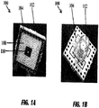
- FIGS. 1A and 1B are schematic diagrams of a front view and a rear view respectively of a first coaxial structure 100, in accordance with an embodiment of the present disclosure.
- the first coaxial structure 100 may be part of a charging device.
- the first coaxial structure 100 may correspond to or be associated with a charging device. In either case, the first coaxial structure 100 may be in electrical communication with a charging device.
- the first coaxial structure 100 is generally square, and includes a transmission line (TL) that produces a transmission-line RF field from a transmitter (i.e., coaxial mode), as further described in reference to FIG. 3A below.
- the shape of the first coaxial structure 100 may alternatively be rectangular, circular, or any other geometric or non-geometric shape.
- the first coaxial structure 100 may include a housing defined by a plurality of sidewalls 102, a top surface 104, and a bottom surface 106.
- the top surface 104 extends over the bottom surface 106.
- the sidewalls 102 span between the top surface 104 and the bottom surface 106.
- the top surface may include vias, as shown, or not include vias.
- the housing is formed of plastic, but alternatively or additionally can be formed of other materials, such as wood, metal, rubber, glass, or any other material that is capable of providing for the functionality described herein. As illustrated in FIGS.
- the first coaxial structure 100 has a generally square shape, but other two-dimensional or three-dimensional shapes are possible, such as a cube, a sphere, a hemisphere, a dome, a cone, a pyramid, or any other polygonal or non-polygonal shape, whether having an open-shape or a closed-shape.
- the housing of the first coaxial structure 100 is waterproof or water-resistant.
- the first coaxial structure 100 may be stiff or flexible and optionally include a non-skid bottom surface to resist movement.
- the top surface 104 may be or include non-skid region(s) or be entirely non-skid to resist motion between the top surface 104 and an electronic device.
- a bracket or other guide may be mounted to the top surface 104 to assist a user with positioning of an electronic device.
- the housing may contain various components of the first coaxial structure 100.
- the first coaxial structure 100 may include a substrate 108.
- the substrate 108 may include metamaterials, or traditional materials such as FR4 or any other material known in the art.
- the metamaterials of the present disclosure may be a broad class of synthetic materials that are engineered to yield permittivity and permeability characteristics compliant with the wireless charging system requirements.
- the metamaterials described herein radiate on their own, and act as very thin reflectors.
- the first coaxial structure 100 may be configured to keep desired currents inside and undesired current outside and thereby retaining the electric current in the first coaxial structure 100.
- the electric current is an RF signal that is carried on the first coaxial structure 100.
- the first coaxial structure 100 may further include a core 110.
- the core 110 is formed at a center of the substrate 108.
- the core 110 is made up of metal to operate as an electrical conductor, as understood in the art.
- the core 110 may be made of any suitable material known in the art without moving out from the scope of the present disclosure.
- the first coaxial structure 100 may further include coaxial connector 112 having two ends where one end of the coaxial connector 112 may extend from the bottom surface 106 and the other end of coaxial connector 112 is connected to a ground terminal.
- FIGS. 2A and 2B are schematic diagrams of a front view and a rear view, respectively, of a second coaxial structure 200, in accordance with an embodiment of the present disclosure.
- the second coaxial structure 200 may be part of an electronic device, such as a mobile telephone, comprising a battery.
- the second coaxial structure 200 may be part of a portable battery device.
- the second coaxial structure 200 may be attached to an electronic device, such as a wearable watch comprising a battery.
- the second coaxial structure 200 may include a housing defined by a plurality of sidewalls 202, a top surface 204, and a bottom surface 206.
- the top surface 204 extends over the bottom surface 206.
- the sidewalls 202 span between the top surface 204 and the bottom surface 206.
- the housing is formed of plastic, but alternatively or additionally can be formed of other materials, such as wood, metal, rubber, glass, or other material that is capable of providing for the functionality described herein. As illustrated in FIGS.
- the second coaxial structure 200 has a generally square shape, but other two-dimensional or three-dimensional shapes are possible, such as a cube, a sphere, a hemisphere, a dome, a cone, a pyramid, or any other polygonal or non-polygonal shape, whether having an open-shape or a closed-shape.
- the housing of the second coaxial structure 200 is waterproof or water-resistant.
- the second coaxial structure 200 may be stiff or flexible and optionally include a non-skid bottom surface to resist movement.
- the top surface 204 may be or include non-skid region(s) or be entirely non-skid to resist motion between the top surface 204 and an electronic device.
- a bracket or other guide may be mounted to the top surface 204 to assist a user with positioning of an electronic device.
- the housing may contain various components of the second coaxial structure 200.
- the second coaxial structure 200 may include a substrate 208.
- the substrate may include metamaterials, or traditional materials such as FR4 or any other material known in the art.
- the metamaterials of the present disclosure may be a broad class of synthetic materials that are engineered to yield permittivity and permeability characteristics compliant with the wireless charging system requirements.
- the metamaterials described herein radiate on their own, and act as very thin reflectors.
- the second coaxial structure 200 may be configured to keep desired currents inside and undesired current outside and thereby retaining the electric current in the second coaxial structure 200.
- the electric current is an RF signal that is carried on the second coaxial structure 200.
- the second coaxial structure 200 may further include a core 210.
- the core 210 is formed at a center of the substrate 208.
- the core 210 is made up of metal to operate as an electrical conductor, as understood in the art.
- the core 210 may be made of any suitable material known in the art without moving out from the scope of the present disclosure.
- the second coaxial structure 200 may further include circuitry 212, such as a transducer device, to convert coaxial field radiation into energy to power or charge a battery of the electronic device.
- circuitry 212 such as a transducer device, to convert coaxial field radiation into energy to power or charge a battery of the electronic device.
- FIG. 3A is an illustration showing excitation of a coaxial structure 302 on a transmitter side, in accordance with some embodiments.
- the coaxial structure 302 is shown to include a sidewall with a copper surface 304, conductor 306, and substrate 308.
- the substrate may be a conventional substrate or otherwise.
- an RF field distribution (mode) 310 occurs in the substrate 308 between the sidewall with copper surface 304 and conductor 306. Size of the coaxial structure 302 may be scaled up or down without limit.
- magnet(s) may be integrated or attached to either or both of the coaxial structures 302 and 312 to help alignment and positioning to maintain the coaxial structures 302 and 312 being near to one another.
- the input impedance of the transmitter unit is akin to an open circuit (that is, the input impedance is infinite) and the receiver unit is not excited with the same RF field distribution (mode) so power is not leaked or otherwise transferred from the coaxial structure 302.
- the receiver unit is excited with the same RF field distribution (mode).
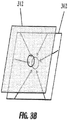
- FIG. 3B is a schematic diagram showing the first coaxial structure 302 of a transmitter and the second coaxial structure 312 of a receiver, in accordance with an embodiment of the present disclosure.
- a more detailed construction of the first coaxial structure 302 is presented above in reference to FIGS. 1A and 1B .
- a more detailed construction of the second coaxial structure 312 is described above in reference to FIGS. 2A and 2B .
- a coaxial field radiation may be excited due to the presence of an electric current in each of the first coaxial structure 302 and the second coaxial structure 312.
- the coaxial field radiation that is excited or otherwise generated results in a distribution of the coaxial field radiation in an area around the first coaxial structure 302 and the second coaxial structure 312, and transfer of the current from the coaxial field radiation may be transferred from the first coaxial structure 302 to the second coaxial structure 312 for conversion by a receiver into power to charge a battery of an electronic device that is coupled to the second coaxial structure 312.
- the proximate distance may be any distance that is less than 10 mm, however it will be appreciated by a person having ordinary skill in the art that the proximate distance is not limited to 10mm or less, and may be more than 10mm without moving out from the scope of the disclosed embodiments.
- a coaxial field radiation may be created due to the presence of electric current in each of the first coaxial structure 302 and the second coaxial structure 312.
- the coaxial field radiation is then distributed in an area around the first coaxial structure 302 and the second coaxial structure 312, and may be converted into power to charge a battery of an electronic device that is coupled to the second coaxial structure 312.
- the surfaces of the first coaxial structure 302 and the second coaxial structure 312 may comprise magnetic properties and/or be configured with magnets that may pull the surfaces of the first coaxial structure 302 and the second coaxial structure 312 towards each other such that the distance between the first coaxial structure 302 and the second coaxial structure 312 is less than a proximate distance.
- a coaxial field radiation may be generated due to the presence of current in the first coaxial structure 302 and, optionally, the second coaxial structure 312.
- a structure such as top surfaces 104 and 204 may have magnetic properties or be configured with magnets to provide attraction properties to bring and maintain the coaxial structures 302 and 312 in proximity to one another.
- the coaxial field radiation 306 may then be converted into power to charge a battery of an electronic device using a suitable circuitry including a rectifier and a power converter.
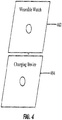
- FIG. 4 is a schematic diagram showing an electronic device 402, in accordance with an embodiment of the present disclosure.
- An exemplary electronic device 402 may be positioned near a charging device 404.
- the electronic device 402 includes a second coaxial structure mounted on the electronic device 402 for charging a battery in the electronic device 402.
- the charging device 404 includes a first coaxial structure. A more detailed construction of the first coaxial structure is described above in reference to FIGS. 1A and 1B . A more detailed construction of the second coaxial structure is described above in reference to FIGS. 2A and 2B .
- the electronic device 402 may include a second coaxial structure, as well as a battery that is to be charged in accordance with the present disclosure.
- the electronic device 402 comprises circuitry including one or more switch elements, a rectifier, and a power converter, where the rectifier and power converter may be combined.
- the second coaxial structure may comprise circuitry including one or more switch elements, a rectifier, and a power converter, where the rectifier and power converter may be combined.
- the second coaxial structure may be positioned within the electronic device 402 and connected to the battery.
- the charging device 404 may include a second coaxial structure.
- a coaxial field radiation is generated due to presence of electric currents in at least the first and second coaxial structure.
- the switch elements may be capable of detecting coaxial field, and directing the radiations to the rectifier when the detected radiations correspond to a power level that exceeds a threshold. For example, in some embodiments, the switch may direct the received coaxial field to the rectifier when the coaxial radiations received are indicative of a wireless power transfer greater than a pre-defined threshold limit. In other embodiments, the switch may direct the received coaxial field when it is indicative of a wireless power transfer greater than a pre-defined limit. This switching acts to protect electronic components of the electronic device 402 from damage and to prevent a power surge from being applied thereto.
- the generated coaxial field is then converted to a power signal by a power conversion circuit, such as a rectifier circuit for charging a battery of the electronic device 402.
- a power conversion circuit such as a rectifier circuit for charging a battery of the electronic device 402.
- the total power output is less than or equal to 1 Watt to conform to Federal Communications Commission (FCC) regulations part 15 (low-power, non-licensed first coaxial structures).
- the rectifier may include diodes, resistors, inductors, and/or capacitors to rectify alternating current (AC) voltage generated to direct current (DC) voltage, as understood in the art.
- the rectifier and switch may be placed as close as is technically possible to minimize losses.
- DC voltage may be regulated and/or conditioned using power converter.
- Power converter can be a DC-DC converter, which may help provide a constant voltage output, regardless of input, to an electronic device or, as in this embodiment, to a battery.
- FIG. 5 is a flow diagram 500 illustrating operation of charging of an electronic device, in accordance with some embodiments of the present disclosure.
- an electronic device with a second coaxial structure may be placed in proximity to a charging device.
- the second coaxial structure may be positioned within or attached to the body of the electronic device.
- the second coaxial structure may be configured to keep desired currents inside and undesired currents outside and thereby maintaining an electric current in the second coaxial structure.
- the charging device may be provided with a first coaxial structure.
- the first coaxial structure may be positioned within or attached to the body of the electronic device.
- the first coaxial structure may be configured to keep desired currents inside and undesired currents outside and thereby maintain an electric current in the first coaxial structure.
- the proximate distance is less than about 10 mm. Other distances to be within a proximate distance are also possible.
- the first planar coaxial structure excites the same RF field distribution (mode) on the second coaxial structure to transfer a charge from the first coaxial structure to the second coaxial structure.
- the electronic device may be charged by converting the coaxial field radiation into a suitable form of energy that is used to power the electronic device.
- the generated coaxial radiation may be converted to a power signal by a power conversion circuit for example rectifier circuit for charging a battery of the electronic device.
- the rectifier may include diodes, resistors, inductors, and/or capacitors to rectify alternating current (AC) voltage generated to direct current (DC) voltage, as understood in the art.
- the total power output is less than or equal to 1 Watt to conform to Federal Communications Commission (FCC) regulations part 15 (low-power, non-licensed first coaxial structures).
- FCC Federal Communications Commission
- process flow diagrams may describe the operations as a sequential process, many of the operations can be performed in parallel or concurrently. In addition, the order of the operations may be rearranged.
- a process may correspond to a method, a function, a procedure, a subroutine, a subprogram, etc. When a process corresponds to a function, its termination may correspond to a return of the function to the calling function or the main function.
Landscapes
- Engineering & Computer Science (AREA)
- Power Engineering (AREA)
- Computer Networks & Wireless Communication (AREA)
- Physics & Mathematics (AREA)
- General Physics & Mathematics (AREA)
- Manufacturing & Machinery (AREA)
- Charge And Discharge Circuits For Batteries Or The Like (AREA)
- Electric Clocks (AREA)
Description
- This application generally relates to wireless charging systems and, more particularly, this application relates to antennas for near field wireless power charging used in conjunction with wireless charging systems.
- Electronic devices, such as laptop computers, smartphones, portable gaming devices, tablets, or others, require power to operate. As generally understood, electronic equipment is often charged at least once a day, or in high-use or power-hungry electronic devices, more than once a day. Such activity may be tedious and may present a burden to some users. For example, a user may be required to carry chargers in case his electronic equipment is lacking power. In addition, some users have to find available power sources to connect to, which is time consuming. Lastly, some users must plug into a wall or some other power supply to be able to charge their electronic device. However, such activity may render electronic devices inoperable or not portable during charging.
- Several attempts have been made to wirelessly transmit energy to electronic devices, where a receiver device can consume the transmission and convert it to usable power. However, most conventional techniques employ antennas that are unable to effectively work when a device to be charged and a wireless charger are placed at a very small distance from each other. For example, conventional solutions may employ a transmitter and a receiver. The transmitter comprises antennas that are configured to radiate electromagnetic waves with a power that is a function of its electric feed signal's power and frequency. The receiver comprises antenna(s) that are configured to receive the power signals transmitted by the transmitter. However, when the transmitter antenna(s) and the receiver antenna(s) are placed too close to each other, the antennas may detune as a result of coupling. During the transmission phase, the tuning is then necessary in order to prevent an unwanted injection of strong currents that could be generated in the reception antenna by a received transmission signal. The unwanted reception of the transmission signal in the reception antenna can only be prevented with the use of the tuning circuit, and it adds to overall cost of the package.
US-2014/292451 A1 describes a blind-mate capacitive coupling interconnection between a main module enclosure one or more sub-module enclosures, having coupling surfaces each with a ground portion and an aperture and an inner element provided in the aperture, spaced away from the ground portion. - Therefore, there is a need in the art to addresses the above described drawbacks of conventional antenna-based wireless charging systems.
- Wireless power systems disclosed herein attempt to address the above drawbacks and may provide a number of other features, as well. Wireless power systems described herein provide coaxial structures that are used in order to charge electronic devices, and thereby solve the above-described drawbacks of antennas used by conventional wireless charging systems.
- In one embodiment, a wireless charging system comprises a first coaxial structure configured to carry an RF signal present on a conductor; and a second coaxial structure configured to be excited by an RF signal from the first coaxial structure, power being transferred from the first coaxial structure to the second coaxial structure when the first coaxial structure and the second coaxial structure are placed in proximity to each other.
- In another embodiment, a method for charging an electronic device in a wireless charging system comprises upon a first planar coaxial structure being proximately positioned to a second planar coaxial structure, exciting the first planar coaxial structure to allow for the transfer of power from the first planar coaxial structure to the second planar coaxial structure.
- In yet another embodiment, a wireless charging system comprises a second coaxial structure configured to be excited by an RF signal, wherein power is transferred from a first coaxial structure having an RF signal present to the second coaxial structure when the first coaxial structure and the second coaxial structure are placed in proximity to each other.
- In another embodiment, a wireless charging system comprises a first coaxial structure carrying an RF signal, and power is transferred from the first coaxial structure to a second coaxial structure when the first coaxial structure and the second coaxial structure are excited in proximity to each other.
- Additional features and advantages of some embodiments will be set forth in the description which follows, and in part will be apparent from the description. The objectives and other advantages of some embodiments will be realized and attained by the example structures described in reference to exemplary embodiments in the written description and claims hereof as well as the appended drawings.
- It is to be understood that both the foregoing general description and the following detailed description are exemplary and explanatory.
- The accompanying drawings constitute a part of this specification and illustrate embodiments of the invention. The present disclosure can be better understood by referring to the following figures. The components in the figures are not necessarily to scale, emphasis instead being placed upon illustrating the principles of the disclosure.
-
FIG. 1A is a schematic diagram of a front view of a first coaxial structure, in accordance with an embodiment of the present disclosure. -
FIG. 1B is a schematic diagram of a rear view of a first coaxial structure, in accordance with an embodiment of the present disclosure. -
FIG. 2A is a schematic diagram of a front view of a second coaxial structure, in accordance with an embodiment of the present disclosure. -
FIG. 2B is a schematic diagram of a rear view of a second coaxial structure, in accordance with an embodiment of the present disclosure. -
FIG. 3A is an illustration of showing excitation of a coaxial structure, in accordance with some embodiments. -
FIG. 3B is a schematic diagram showing a first coaxial structure and a second coaxial structure, in accordance with an embodiment of the present disclosure. -
FIG. 4 is a schematic diagram showing an electronic device, in accordance with an embodiment of the present disclosure. -
FIG. 5 is a flow diagram illustrating operation of charging of an electronic device in accordance with some embodiments of the present disclosure. - Reference will now be made to the exemplary embodiments illustrated in the drawings, where specific language will be used here to describe the same. It should be understood that no limitation of the scope of the invention is intended by the descriptions of such exemplary embodiments. Alterations and further modifications of the exemplary embodiments and additional applications implementing the principles of the inventive features, which would occur to a person skilled in the relevant art and having possession of this disclosure, are to be considered within the scope of this disclosure.
- Electronic devices, especially wearable devices, have to be charged regularly. Wireless charging simplifies the charging process. A charger may include a power generator, and the electronic device may include a receiver for receiving a transfer of wireless energy. Each of the power generator and receiver may include a coaxial structure that provides for the wireless transfer of energy, as described herein. As a summary, when the receiver coaxial structure is not near the transmitter coaxial structure, input impedance of the transmitter coaxial structure is akin to open circuit, therefore, power is not leaked out of the transmitter coaxial structure. Power transfer happens when the receiver coaxial structure is placed near the transmitter coaxial structure and the receiver coaxial structure is excited with the same RF field distribution (mode) as the transmitter coaxial structure.
-
FIGS. 1A and 1B are schematic diagrams of a front view and a rear view respectively of a firstcoaxial structure 100, in accordance with an embodiment of the present disclosure. In one embodiment, the firstcoaxial structure 100 may be part of a charging device. In another embodiment, the firstcoaxial structure 100 may correspond to or be associated with a charging device. In either case, the firstcoaxial structure 100 may be in electrical communication with a charging device. As shown, the firstcoaxial structure 100 is generally square, and includes a transmission line (TL) that produces a transmission-line RF field from a transmitter (i.e., coaxial mode), as further described in reference toFIG. 3A below. The shape of the firstcoaxial structure 100 may alternatively be rectangular, circular, or any other geometric or non-geometric shape. - The first
coaxial structure 100 may include a housing defined by a plurality ofsidewalls 102, atop surface 104, and abottom surface 106. Thetop surface 104 extends over thebottom surface 106. Thesidewalls 102 span between thetop surface 104 and thebottom surface 106. The top surface may include vias, as shown, or not include vias. In some embodiments, the housing is formed of plastic, but alternatively or additionally can be formed of other materials, such as wood, metal, rubber, glass, or any other material that is capable of providing for the functionality described herein. As illustrated inFIGS. 1A and 1B , the firstcoaxial structure 100 has a generally square shape, but other two-dimensional or three-dimensional shapes are possible, such as a cube, a sphere, a hemisphere, a dome, a cone, a pyramid, or any other polygonal or non-polygonal shape, whether having an open-shape or a closed-shape. In some embodiments, the housing of the firstcoaxial structure 100 is waterproof or water-resistant. - The first
coaxial structure 100 may be stiff or flexible and optionally include a non-skid bottom surface to resist movement. Similarly, thetop surface 104 may be or include non-skid region(s) or be entirely non-skid to resist motion between thetop surface 104 and an electronic device. Still yet, a bracket or other guide may be mounted to thetop surface 104 to assist a user with positioning of an electronic device. The housing may contain various components of the firstcoaxial structure 100. - The first
coaxial structure 100 may include asubstrate 108. Thesubstrate 108 may include metamaterials, or traditional materials such as FR4 or any other material known in the art. The metamaterials of the present disclosure may be a broad class of synthetic materials that are engineered to yield permittivity and permeability characteristics compliant with the wireless charging system requirements. The metamaterials described herein radiate on their own, and act as very thin reflectors. - The first
coaxial structure 100 may be configured to keep desired currents inside and undesired current outside and thereby retaining the electric current in the firstcoaxial structure 100. In the exemplary embodiment, the electric current is an RF signal that is carried on the firstcoaxial structure 100. The firstcoaxial structure 100 may further include acore 110. Thecore 110 is formed at a center of thesubstrate 108. In one embodiment, thecore 110 is made up of metal to operate as an electrical conductor, as understood in the art. In another embodiment, thecore 110 may be made of any suitable material known in the art without moving out from the scope of the present disclosure. - The first
coaxial structure 100 may further includecoaxial connector 112 having two ends where one end of thecoaxial connector 112 may extend from thebottom surface 106 and the other end ofcoaxial connector 112 is connected to a ground terminal. -
FIGS. 2A and 2B are schematic diagrams of a front view and a rear view, respectively, of a secondcoaxial structure 200, in accordance with an embodiment of the present disclosure. In one embodiment, the secondcoaxial structure 200 may be part of an electronic device, such as a mobile telephone, comprising a battery. In another embodiment, the secondcoaxial structure 200 may be part of a portable battery device. In yet another embodiment, the secondcoaxial structure 200 may be attached to an electronic device, such as a wearable watch comprising a battery. - The second
coaxial structure 200 may include a housing defined by a plurality ofsidewalls 202, atop surface 204, and abottom surface 206. Thetop surface 204 extends over thebottom surface 206. Thesidewalls 202 span between thetop surface 204 and thebottom surface 206. In some embodiments, the housing is formed of plastic, but alternatively or additionally can be formed of other materials, such as wood, metal, rubber, glass, or other material that is capable of providing for the functionality described herein. As illustrated inFIGS. 2A and 2B , the secondcoaxial structure 200 has a generally square shape, but other two-dimensional or three-dimensional shapes are possible, such as a cube, a sphere, a hemisphere, a dome, a cone, a pyramid, or any other polygonal or non-polygonal shape, whether having an open-shape or a closed-shape. In some embodiments, the housing of the secondcoaxial structure 200 is waterproof or water-resistant. - The second
coaxial structure 200 may be stiff or flexible and optionally include a non-skid bottom surface to resist movement. Similarly, thetop surface 204 may be or include non-skid region(s) or be entirely non-skid to resist motion between thetop surface 204 and an electronic device. Still yet, a bracket or other guide may be mounted to thetop surface 204 to assist a user with positioning of an electronic device. The housing may contain various components of the secondcoaxial structure 200. - The second
coaxial structure 200 may include asubstrate 208. The substrate may include metamaterials, or traditional materials such as FR4 or any other material known in the art. The metamaterials of the present disclosure may be a broad class of synthetic materials that are engineered to yield permittivity and permeability characteristics compliant with the wireless charging system requirements. The metamaterials described herein radiate on their own, and act as very thin reflectors. - The second
coaxial structure 200 may be configured to keep desired currents inside and undesired current outside and thereby retaining the electric current in the secondcoaxial structure 200. In the exemplary embodiment, the electric current is an RF signal that is carried on the secondcoaxial structure 200. The secondcoaxial structure 200 may further include acore 210. Thecore 210 is formed at a center of thesubstrate 208. In one embodiment, thecore 210 is made up of metal to operate as an electrical conductor, as understood in the art. In another embodiment, thecore 210 may be made of any suitable material known in the art without moving out from the scope of the present disclosure. - The second
coaxial structure 200 may further includecircuitry 212, such as a transducer device, to convert coaxial field radiation into energy to power or charge a battery of the electronic device. -
FIG. 3A is an illustration showing excitation of acoaxial structure 302 on a transmitter side, in accordance with some embodiments. Thecoaxial structure 302 is shown to include a sidewall with acopper surface 304,conductor 306, andsubstrate 308. The substrate may be a conventional substrate or otherwise. When thecoaxial structure 302 is excited, an RF field distribution (mode) 310 occurs in thesubstrate 308 between the sidewall withcopper surface 304 andconductor 306. Size of thecoaxial structure 302 may be scaled up or down without limit. The coaxial structures 302 (FIG. 3A ) and 312 (FIG. 3B ) may be identical and reciprocal in structure or be different in structure but be complementary in that the twocoaxial structures coaxial structures coaxial structures coaxial structures coaxial structures - In operation, when a
coaxial structure 312 on the receiver side (seeFIG. 3B ) is not positioned near thecoaxial structure 302 of the transmitter side, as shown inFIG. 3A , the input impedance of the transmitter unit is akin to an open circuit (that is, the input impedance is infinite) and the receiver unit is not excited with the same RF field distribution (mode) so power is not leaked or otherwise transferred from thecoaxial structure 302. However, when thecoaxial structure 312 on a receiver side is positioned near thecoaxial structure 302, as shown inFIG. 3B , the receiver unit is excited with the same RF field distribution (mode). -
FIG. 3B is a schematic diagram showing the firstcoaxial structure 302 of a transmitter and the secondcoaxial structure 312 of a receiver, in accordance with an embodiment of the present disclosure. A more detailed construction of the firstcoaxial structure 302 is presented above in reference toFIGS. 1A and 1B . A more detailed construction of the secondcoaxial structure 312 is described above in reference toFIGS. 2A and 2B . - In the illustrated embodiment of
FIG. 3B , when the surfaces of the firstcoaxial structure 302 and the secondcoaxial structure 312 are positioned at a proximate distance from each other, a coaxial field radiation may be excited due to the presence of an electric current in each of the firstcoaxial structure 302 and the secondcoaxial structure 312. The coaxial field radiation that is excited or otherwise generated results in a distribution of the coaxial field radiation in an area around the firstcoaxial structure 302 and the secondcoaxial structure 312, and transfer of the current from the coaxial field radiation may be transferred from the firstcoaxial structure 302 to the secondcoaxial structure 312 for conversion by a receiver into power to charge a battery of an electronic device that is coupled to the secondcoaxial structure 312. In the illustrated embodiment, the proximate distance may be any distance that is less than 10 mm, however it will be appreciated by a person having ordinary skill in the art that the proximate distance is not limited to 10mm or less, and may be more than 10mm without moving out from the scope of the disclosed embodiments. - In another embodiment, when the surfaces of the first
coaxial structure 302 and the secondcoaxial structure 312 are touched to each other, a coaxial field radiation may be created due to the presence of electric current in each of the firstcoaxial structure 302 and the secondcoaxial structure 312. The coaxial field radiation is then distributed in an area around the firstcoaxial structure 302 and the secondcoaxial structure 312, and may be converted into power to charge a battery of an electronic device that is coupled to the secondcoaxial structure 312. - In one embodiment, the surfaces of the first
coaxial structure 302 and the secondcoaxial structure 312 may comprise magnetic properties and/or be configured with magnets that may pull the surfaces of the firstcoaxial structure 302 and the secondcoaxial structure 312 towards each other such that the distance between the firstcoaxial structure 302 and the secondcoaxial structure 312 is less than a proximate distance. When the firstcoaxial structure 302 and the secondcoaxial structure 312 are proximately positioned, a coaxial field radiation may be generated due to the presence of current in the firstcoaxial structure 302 and, optionally, the secondcoaxial structure 312. When bothcoaxial structures coaxial structure 302 to the secondcoaxial structure 312. In an alternative embodiment, a structure, such astop surfaces coaxial structures coaxial field radiation 306 may then be converted into power to charge a battery of an electronic device using a suitable circuitry including a rectifier and a power converter. -
FIG. 4 is a schematic diagram showing anelectronic device 402, in accordance with an embodiment of the present disclosure. An exemplaryelectronic device 402 may be positioned near acharging device 404. Theelectronic device 402 includes a second coaxial structure mounted on theelectronic device 402 for charging a battery in theelectronic device 402. The chargingdevice 404 includes a first coaxial structure. A more detailed construction of the first coaxial structure is described above in reference toFIGS. 1A and 1B . A more detailed construction of the second coaxial structure is described above in reference toFIGS. 2A and 2B . - The
electronic device 402 may include a second coaxial structure, as well as a battery that is to be charged in accordance with the present disclosure. In some embodiments, theelectronic device 402 comprises circuitry including one or more switch elements, a rectifier, and a power converter, where the rectifier and power converter may be combined. In some embodiments, the second coaxial structure may comprise circuitry including one or more switch elements, a rectifier, and a power converter, where the rectifier and power converter may be combined. The second coaxial structure may be positioned within theelectronic device 402 and connected to the battery. - The charging
device 404 may include a second coaxial structure. When theelectronic device 402 and thecharging device 404 are brought close to each other such that the distance between theelectronic device 402 and thecharging device 404 is less than the proximate distance, then a coaxial field radiation is generated due to presence of electric currents in at least the first and second coaxial structure. - The switch elements may be capable of detecting coaxial field, and directing the radiations to the rectifier when the detected radiations correspond to a power level that exceeds a threshold. For example, in some embodiments, the switch may direct the received coaxial field to the rectifier when the coaxial radiations received are indicative of a wireless power transfer greater than a pre-defined threshold limit. In other embodiments, the switch may direct the received coaxial field when it is indicative of a wireless power transfer greater than a pre-defined limit. This switching acts to protect electronic components of the
electronic device 402 from damage and to prevent a power surge from being applied thereto. - The generated coaxial field is then converted to a power signal by a power conversion circuit, such as a rectifier circuit for charging a battery of the
electronic device 402. In some embodiments, the total power output is less than or equal to 1 Watt to conform to Federal Communications Commission (FCC) regulations part 15 (low-power, non-licensed first coaxial structures). In an embodiment, the rectifier may include diodes, resistors, inductors, and/or capacitors to rectify alternating current (AC) voltage generated to direct current (DC) voltage, as understood in the art. In some embodiments, the rectifier and switch may be placed as close as is technically possible to minimize losses. After rectifying AC voltage, DC voltage may be regulated and/or conditioned using power converter. Power converter can be a DC-DC converter, which may help provide a constant voltage output, regardless of input, to an electronic device or, as in this embodiment, to a battery. -
FIG. 5 is a flow diagram 500 illustrating operation of charging of an electronic device, in accordance with some embodiments of the present disclosure. - At step 502, an electronic device with a second coaxial structure may be placed in proximity to a charging device. The second coaxial structure may be positioned within or attached to the body of the electronic device. The second coaxial structure may be configured to keep desired currents inside and undesired currents outside and thereby maintaining an electric current in the second coaxial structure.
- The charging device may be provided with a first coaxial structure. The first coaxial structure may be positioned within or attached to the body of the electronic device. The first coaxial structure may be configured to keep desired currents inside and undesired currents outside and thereby maintain an electric current in the first coaxial structure.
- At step 504, in response to the electronic device being positioned in a proximate distance to the charging device, power may be transferred from the charging device to the electronic device. In one embodiment, the proximate distance is less than about 10 mm. Other distances to be within a proximate distance are also possible. Upon a planar surface of the first coaxial structure being proximately positioned to a planar surface of the second coaxial structure, the first planar coaxial structure excites the same RF field distribution (mode) on the second coaxial structure to transfer a charge from the first coaxial structure to the second coaxial structure.
- At
step 506, the electronic device may be charged by converting the coaxial field radiation into a suitable form of energy that is used to power the electronic device. The generated coaxial radiation may be converted to a power signal by a power conversion circuit for example rectifier circuit for charging a battery of the electronic device. The rectifier may include diodes, resistors, inductors, and/or capacitors to rectify alternating current (AC) voltage generated to direct current (DC) voltage, as understood in the art. In some embodiments, the total power output is less than or equal to 1 Watt to conform to Federal Communications Commission (FCC) regulations part 15 (low-power, non-licensed first coaxial structures). - The foregoing method descriptions and flow diagrams are provided merely as illustrative examples and are not intended to require or imply that the steps of the various embodiments must be performed in the order presented. The steps in the foregoing embodiments may be performed in any order. Words such as "then," "next," etc., are not intended to limit the order of the steps; these words are simply used to guide the reader through the description of the methods. Although process flow diagrams may describe the operations as a sequential process, many of the operations can be performed in parallel or concurrently. In addition, the order of the operations may be rearranged. A process may correspond to a method, a function, a procedure, a subroutine, a subprogram, etc. When a process corresponds to a function, its termination may correspond to a return of the function to the calling function or the main function.
- The various illustrative logical blocks, modules, circuits, and algorithm steps described in connection with the embodiments disclosed herein may be implemented as electronic hardware, computer software, or combinations of both. To clearly illustrate this interchangeability of hardware and software, various illustrative components, blocks, modules, circuits, and steps have been described above generally in terms of their functionality. Whether such functionality is implemented as hardware or software depends upon the particular application and design constraints imposed on the overall system. Skilled artisans may implement the described functionality in varying ways for each particular application, but such implementation decisions should not be interpreted as causing a departure from the scope of the present invention.
- The preceding description of the disclosed embodiments is provided to enable any person skilled in the art to make or use the present invention. Various modifications to these embodiments will be readily apparent to those skilled in the art, and the generic principles defined herein may be applied to other embodiments without departing from the scope of the invention as defined by the claims.
Claims (15)
- A wireless charging system comprising:a transmitter coaxial structure (100) comprising a first substrate (108) and a first metallic core (110) formed at a center of the first substrate (108); anda receiver coaxial structure (200) comprising a second substrate (208) and a second metallic core (210) formed at a center of the second substrate (208), wherein:the transmitter coaxial structure (100) is configured to carry a radio frequency, RF, signal present on the first metallic core (110) and generate a coaxial field radiation distributed in an area around the transmitter coaxial structure (100) when the transmitter coaxial structure (100) and the receiver coaxial structure (200) are placed in proximity to each other;the receiver coaxial structure (200) is configured to:receive the RF signal from the transmitter coaxial structure (100), the RF signal being transferred from the transmitter coaxial structure (100) to the receiver coaxial structure (200) as part of the coaxial field radiation when the transmitter coaxial structure (100) and the receiver-coaxial structure (200) are placed in proximity to each other; andconvert the received RF signal into energy to power and/or charge an electronic device coupled to the receiver coaxial structure (200).
- The system of claim 1, wherein:the transmitter coaxial structure (100) is situated in a charging device,the receiver coaxial structure (200) is situated in an electronic device, andthe RF signal is transferred in response to a surface of the electronic device being touched to a surface of the charging device.
- The system of claim 1, wherein the predetermined proximity is less than about 10mm.
- The system of claim 1, wherein the transmitter coaxial structure (100) and receiver coaxial structure (200) include respective planar surfaces configured to be positioned in proximity to each other.
- The system of claim 4, wherein the respective planar surfaces are positioned in proximity to each other and in parallel with one another.
- The system of claim 1, wherein the first substrate (108) comprises a metamaterial.
- The system of claim 1, wherein the second substrate (208) comprises a metamaterial.
- The system of claim 2, further comprising a magnet attached to each of the charging device and the electronic device so as to cause the electronic device and the charging device to be pulled towards each other when the transmitter coaxial structure (100) and the receiver coaxial structure (200) are placed in proximity to each other.
- A method for charging an electronic device, the method comprising:at a wireless charging system that includes: (i) a transmitter coaxial structure (100) comprising a first substrate (108) and a first metallic core (110) formed at a center of the first substrate (108), and (ii) a receiver coaxial structure (200) comprising a second substrate (208_ and a second metallic core (210) formed at a center of the second substrate (208):
upon the transmitter coaxial structure (100) being positioned within a predetermined proximate distance of the receiver coaxial structure (200):
generating, by the transmitter coaxial structure (100), a coaxial field radiation distributed in an area around the transmitter coaxial structure (100) to allow for a transfer of power from the transmitter coaxial structure (100) to the receiver coaxial structure (200),wherein:
the receiver coaxial structure (200) receives power from the coaxial field radiation generated by the transmitter coaxial structure (100), the coaxial field radiation including a radio frequency signal; and
the receiver coaxial structure (200) converts the RF signal into energy to power and/or charge an electronic device coupled to the receiver coaxial structure (200). - The method of claim 9, wherein:the transmitter coaxial structure (100) is situated in a charging device,the receiver coaxial structure (200) is situated in an electronic device, andthe RF signal is transferred in response to a surface of the electronic device being touched to a surface of the charging device.
- The method of claim 9, wherein the transmitter coaxial structure (100) is positioned in proximity to the receiver coaxial structure (200) and in parallel to the receiver coaxial structure (200).
- The method of claim 9, wherein the predetermined proximity of the transmitter coaxial structure (100) and receiver coaxial structure (200) is less than about 10 mm.
- The method of claim 9, wherein the first substrate (108) comprises a metamaterial.
- The method of claim 9, wherein the second substrate (208) comprises a metamaterial.
- The method of claim 10, wherein a respective magnet is attached to each of the charging device and the electronic device so as to cause the electronic device and the charging device to be pulled towards each other.
Applications Claiming Priority (3)
| Application Number | Priority Date | Filing Date | Title |
|---|---|---|---|
| US201562387206P | 2015-12-24 | 2015-12-24 | |
| US15/046,026 US10256657B2 (en) | 2015-12-24 | 2016-02-17 | Antenna having coaxial structure for near field wireless power charging |
| PCT/US2016/068498 WO2017112924A1 (en) | 2015-12-24 | 2016-12-23 | Antenna for near field wireless power charging |
Publications (3)
| Publication Number | Publication Date |
|---|---|
| EP3394954A1 EP3394954A1 (en) | 2018-10-31 |
| EP3394954A4 EP3394954A4 (en) | 2019-08-14 |
| EP3394954B1 true EP3394954B1 (en) | 2020-12-02 |
Family
ID=59087423
Family Applications (1)
| Application Number | Title | Priority Date | Filing Date |
|---|---|---|---|
| EP16880139.7A Active EP3394954B1 (en) | 2015-12-24 | 2016-12-23 | Antenna for near field wireless power charging |
Country Status (6)
| Country | Link |
|---|---|
| US (2) | US10256657B2 (en) |
| EP (1) | EP3394954B1 (en) |
| JP (1) | JP6665304B2 (en) |
| KR (1) | KR20180093074A (en) |
| CN (1) | CN108541351B (en) |
| WO (1) | WO2017112924A1 (en) |
Families Citing this family (64)
| Publication number | Priority date | Publication date | Assignee | Title |
|---|---|---|---|---|
| US9787103B1 (en) | 2013-08-06 | 2017-10-10 | Energous Corporation | Systems and methods for wirelessly delivering power to electronic devices that are unable to communicate with a transmitter |
| US10256657B2 (en) | 2015-12-24 | 2019-04-09 | Energous Corporation | Antenna having coaxial structure for near field wireless power charging |
| US10312715B2 (en) | 2015-09-16 | 2019-06-04 | Energous Corporation | Systems and methods for wireless power charging |
| US10992187B2 (en) | 2012-07-06 | 2021-04-27 | Energous Corporation | System and methods of using electromagnetic waves to wirelessly deliver power to electronic devices |
| US12057715B2 (en) | 2012-07-06 | 2024-08-06 | Energous Corporation | Systems and methods of wirelessly delivering power to a wireless-power receiver device in response to a change of orientation of the wireless-power receiver device |
| US10439448B2 (en) | 2014-08-21 | 2019-10-08 | Energous Corporation | Systems and methods for automatically testing the communication between wireless power transmitter and wireless power receiver |
| US10965164B2 (en) | 2012-07-06 | 2021-03-30 | Energous Corporation | Systems and methods of wirelessly delivering power to a receiver device |
| US9867062B1 (en) | 2014-07-21 | 2018-01-09 | Energous Corporation | System and methods for using a remote server to authorize a receiving device that has requested wireless power and to determine whether another receiving device should request wireless power in a wireless power transmission system |
| US9825674B1 (en) | 2014-05-23 | 2017-11-21 | Energous Corporation | Enhanced transmitter that selects configurations of antenna elements for performing wireless power transmission and receiving functions |
| US10992185B2 (en) | 2012-07-06 | 2021-04-27 | Energous Corporation | Systems and methods of using electromagnetic waves to wirelessly deliver power to game controllers |
| US11502551B2 (en) | 2012-07-06 | 2022-11-15 | Energous Corporation | Wirelessly charging multiple wireless-power receivers using different subsets of an antenna array to focus energy at different locations |
| US10381880B2 (en) | 2014-07-21 | 2019-08-13 | Energous Corporation | Integrated antenna structure arrays for wireless power transmission |
| US9876394B1 (en) | 2014-05-07 | 2018-01-23 | Energous Corporation | Boost-charger-boost system for enhanced power delivery |
| US10063105B2 (en) | 2013-07-11 | 2018-08-28 | Energous Corporation | Proximity transmitters for wireless power charging systems |
| US10158257B2 (en) | 2014-05-01 | 2018-12-18 | Energous Corporation | System and methods for using sound waves to wirelessly deliver power to electronic devices |
| US10068703B1 (en) | 2014-07-21 | 2018-09-04 | Energous Corporation | Integrated miniature PIFA with artificial magnetic conductor metamaterials |
| US12283828B2 (en) | 2015-09-15 | 2025-04-22 | Energous Corporation | Receiver devices configured to determine location within a transmission field |
| US10523033B2 (en) | 2015-09-15 | 2019-12-31 | Energous Corporation | Receiver devices configured to determine location within a transmission field |
| US11710321B2 (en) | 2015-09-16 | 2023-07-25 | Energous Corporation | Systems and methods of object detection in wireless power charging systems |
| US10778041B2 (en) | 2015-09-16 | 2020-09-15 | Energous Corporation | Systems and methods for generating power waves in a wireless power transmission system |
| US10734717B2 (en) | 2015-10-13 | 2020-08-04 | Energous Corporation | 3D ceramic mold antenna |
| US10027180B1 (en) | 2015-11-02 | 2018-07-17 | Energous Corporation | 3D triple linear antenna that acts as heat sink |
| US10063108B1 (en) | 2015-11-02 | 2018-08-28 | Energous Corporation | Stamped three-dimensional antenna |
| US10038332B1 (en) | 2015-12-24 | 2018-07-31 | Energous Corporation | Systems and methods of wireless power charging through multiple receiving devices |
| US10079515B2 (en) | 2016-12-12 | 2018-09-18 | Energous Corporation | Near-field RF charging pad with multi-band antenna element with adaptive loading to efficiently charge an electronic device at any position on the pad |
| US10027159B2 (en) | 2015-12-24 | 2018-07-17 | Energous Corporation | Antenna for transmitting wireless power signals |
| US11863001B2 (en) | 2015-12-24 | 2024-01-02 | Energous Corporation | Near-field antenna for wireless power transmission with antenna elements that follow meandering patterns |
| US10923954B2 (en) | 2016-11-03 | 2021-02-16 | Energous Corporation | Wireless power receiver with a synchronous rectifier |
| JP6691273B2 (en) | 2016-12-12 | 2020-04-28 | エナージャス コーポレイション | A method for selectively activating the antenna area of a near-field charging pad to maximize delivered wireless power |
| US10389161B2 (en) | 2017-03-15 | 2019-08-20 | Energous Corporation | Surface mount dielectric antennas for wireless power transmitters |
| US10680319B2 (en) | 2017-01-06 | 2020-06-09 | Energous Corporation | Devices and methods for reducing mutual coupling effects in wireless power transmission systems |
| US10439442B2 (en) | 2017-01-24 | 2019-10-08 | Energous Corporation | Microstrip antennas for wireless power transmitters |
| WO2018183892A1 (en) | 2017-03-30 | 2018-10-04 | Energous Corporation | Flat antennas having two or more resonant frequencies for use in wireless power transmission systems |
| US10511097B2 (en) | 2017-05-12 | 2019-12-17 | Energous Corporation | Near-field antennas for accumulating energy at a near-field distance with minimal far-field gain |
| US11462949B2 (en) | 2017-05-16 | 2022-10-04 | Wireless electrical Grid LAN, WiGL Inc | Wireless charging method and system |
| US12074460B2 (en) | 2017-05-16 | 2024-08-27 | Wireless Electrical Grid Lan, Wigl Inc. | Rechargeable wireless power bank and method of using |
| US12074452B2 (en) | 2017-05-16 | 2024-08-27 | Wireless Electrical Grid Lan, Wigl Inc. | Networked wireless charging system |
| US10848853B2 (en) | 2017-06-23 | 2020-11-24 | Energous Corporation | Systems, methods, and devices for utilizing a wire of a sound-producing device as an antenna for receipt of wirelessly delivered power |
| US10122219B1 (en) | 2017-10-10 | 2018-11-06 | Energous Corporation | Systems, methods, and devices for using a battery as a antenna for receiving wirelessly delivered power from radio frequency power waves |
| US11342798B2 (en) | 2017-10-30 | 2022-05-24 | Energous Corporation | Systems and methods for managing coexistence of wireless-power signals and data signals operating in a same frequency band |
| US10615647B2 (en) | 2018-02-02 | 2020-04-07 | Energous Corporation | Systems and methods for detecting wireless power receivers and other objects at a near-field charging pad |
| US11159057B2 (en) | 2018-03-14 | 2021-10-26 | Energous Corporation | Loop antennas with selectively-activated feeds to control propagation patterns of wireless power signals |
| US11515732B2 (en) | 2018-06-25 | 2022-11-29 | Energous Corporation | Power wave transmission techniques to focus wirelessly delivered power at a receiving device |
| US11522382B1 (en) | 2018-08-03 | 2022-12-06 | William Vahle | Wireless mobile battery |
| US11437735B2 (en) | 2018-11-14 | 2022-09-06 | Energous Corporation | Systems for receiving electromagnetic energy using antennas that are minimally affected by the presence of the human body |
| US11539243B2 (en) | 2019-01-28 | 2022-12-27 | Energous Corporation | Systems and methods for miniaturized antenna for wireless power transmissions |
| CN113661660B (en) | 2019-02-06 | 2023-01-24 | 艾诺格思公司 | Method for estimating optimal phase, wireless power transmitting device and storage medium |
| US12155231B2 (en) | 2019-04-09 | 2024-11-26 | Energous Corporation | Asymmetric spiral antennas for wireless power transmission and reception |
| USD943520S1 (en) * | 2019-07-11 | 2022-02-15 | Mitsubishi Electric Corporation | Wireless charging floor panel |
| WO2021055901A1 (en) | 2019-09-20 | 2021-03-25 | Energous Corporation | Asymmetric spiral antennas with parasitic elements for wireless power transmission |
| US11381118B2 (en) | 2019-09-20 | 2022-07-05 | Energous Corporation | Systems and methods for machine learning based foreign object detection for wireless power transmission |
| US11411441B2 (en) | 2019-09-20 | 2022-08-09 | Energous Corporation | Systems and methods of protecting wireless power receivers using multiple rectifiers and establishing in-band communications using multiple rectifiers |
| WO2021055898A1 (en) | 2019-09-20 | 2021-03-25 | Energous Corporation | Systems and methods for machine learning based foreign object detection for wireless power transmission |
| WO2021055900A1 (en) | 2019-09-20 | 2021-03-25 | Energous Corporation | Classifying and detecting foreign objects using a power amplifier controller integrated circuit in wireless power transmission systems |
| US11355966B2 (en) | 2019-12-13 | 2022-06-07 | Energous Corporation | Charging pad with guiding contours to align an electronic device on the charging pad and efficiently transfer near-field radio-frequency energy to the electronic device |
| US10985617B1 (en) | 2019-12-31 | 2021-04-20 | Energous Corporation | System for wirelessly transmitting energy at a near-field distance without using beam-forming control |
| US11799324B2 (en) | 2020-04-13 | 2023-10-24 | Energous Corporation | Wireless-power transmitting device for creating a uniform near-field charging area |
| US11469629B2 (en) | 2020-08-12 | 2022-10-11 | Energous Corporation | Systems and methods for secure wireless transmission of power using unidirectional communication signals from a wireless-power-receiving device |
| US12306285B2 (en) | 2020-12-01 | 2025-05-20 | Energous Corporation | Systems and methods for using one or more sensors to detect and classify objects in a keep-out zone of a wireless-power transmission field, and antennas with integrated sensor arrangements |
| US20220255360A1 (en) * | 2021-02-10 | 2022-08-11 | Energous Corporation | Battery module configured to enable smart rings of various sizes to have radio-frequency wireless charging capabilities, and a wireless charger device to wirelessly deliver power to the smart rings |
| US11916398B2 (en) | 2021-12-29 | 2024-02-27 | Energous Corporation | Small form-factor devices with integrated and modular harvesting receivers, and shelving-mounted wireless-power transmitters for use therewith |
| USD1023927S1 (en) * | 2022-03-08 | 2024-04-23 | Witricity Corporation | Wireless power transfer pad |
| USD1018474S1 (en) | 2022-03-18 | 2024-03-19 | Witricity Corporation | Electrical-box cover |
| US12142939B2 (en) | 2022-05-13 | 2024-11-12 | Energous Corporation | Integrated wireless-power-transmission platform designed to operate in multiple bands, and multi-band antennas for use therewith |
Family Cites Families (1111)
| Publication number | Priority date | Publication date | Assignee | Title |
|---|---|---|---|---|
| US787412A (en) | 1900-05-16 | 1905-04-18 | Nikola Tesla | Art of transmitting electrical energy through the natural mediums. |
| US2811624A (en) | 1954-01-07 | 1957-10-29 | Raytheon Mfg Co | Radiation systems |
| US2863148A (en) | 1954-06-17 | 1958-12-02 | Emi Ltd | Helical antenna enclosed in a dielectric |
| GB927051A (en) | 1959-10-07 | 1963-05-22 | Rudolf Guertler | Improvements in or relating to antennas for high frequencies |
| US3434678A (en) | 1965-05-05 | 1969-03-25 | Raytheon Co | Microwave to dc converter |
| US4944036A (en) | 1970-12-28 | 1990-07-24 | Hyatt Gilbert P | Signature filter system |
| US3696384A (en) | 1971-07-08 | 1972-10-03 | Recognition Devices | Ultrasonic tracking and locating system |
| US3754269A (en) | 1972-03-07 | 1973-08-21 | Vorta Systems Inc | Omni-directional antenna mounted in circular radome |
| US4101895A (en) | 1977-02-14 | 1978-07-18 | The United States Of America As Represented By The Secretary Of The Army | Multifrequency antenna system integrated into a radome |
| US4360741A (en) | 1980-10-06 | 1982-11-23 | The Boeing Company | Combined antenna-rectifier arrays for power distribution systems |
| US7663502B2 (en) | 1992-05-05 | 2010-02-16 | Intelligent Technologies International, Inc. | Asset system control arrangement and method |
| US4995010A (en) | 1989-07-21 | 1991-02-19 | Johnson Fishing, Inc. | Depth finding-trolling system |
| US5211471A (en) | 1990-12-28 | 1993-05-18 | The Brinkmann Corporation | Flashlight with tailcap switch boot |
| US5200759A (en) | 1991-06-03 | 1993-04-06 | Mcginnis Henry J | Telecommunications tower equipment housing |
| US6738697B2 (en) | 1995-06-07 | 2004-05-18 | Automotive Technologies International Inc. | Telematics system for vehicle diagnostics |
| US6748797B2 (en) | 2000-09-08 | 2004-06-15 | Automotive Technologies International Inc. | Method and apparatus for monitoring tires |
| US5556749A (en) | 1992-11-12 | 1996-09-17 | Hitachi Chemical Research Center, Inc. | Oligoprobe designstation: a computerized method for designing optimal DNA probes |
| US6069412A (en) | 1993-03-29 | 2000-05-30 | Powerware Corporation | Power factor corrected UPS with improved connection of battery to neutral |
| US5422647A (en) | 1993-05-07 | 1995-06-06 | Space Systems/Loral, Inc. | Mobile communication satellite payload |
| US5631572A (en) | 1993-09-17 | 1997-05-20 | Teradyne, Inc. | Printed circuit board tester using magnetic induction |
| US6664920B1 (en) | 1993-11-18 | 2003-12-16 | Raytheon Company | Near-range microwave detection for frequency-modulation continuous-wave and stepped frequency radar systems |
| US5574967A (en) | 1994-01-11 | 1996-11-12 | Ericsson Ge Mobile Communications, Inc. | Waste energy control and management in power amplifiers |
| US5712642A (en) | 1994-09-27 | 1998-01-27 | Hughes Missile Systems Company | Spatial power combiner using subharmonic beam position control |
| US5646633A (en) | 1995-04-05 | 1997-07-08 | Mcdonnell Douglas Corporation | Microstrip antenna having a plurality of broken loops |
| JPH0951293A (en) | 1995-05-30 | 1997-02-18 | Matsushita Electric Ind Co Ltd | Indoor wireless communication system |
| US9443358B2 (en) | 1995-06-07 | 2016-09-13 | Automotive Vehicular Sciences LLC | Vehicle software upgrade techniques |
| US8112131B2 (en) | 1996-02-20 | 2012-02-07 | Chester Holdings LLC | Radiative focal area antenna transmission coupling arrangement |
| US7043543B2 (en) | 1996-07-23 | 2006-05-09 | Server Technology, Inc. | Vertical-mount electrical power distribution plugstrip |
| US8183998B2 (en) | 1996-12-16 | 2012-05-22 | Ip Holdings, Inc. | System for seamless and secure networking of implantable medical devices, electronic patch devices and wearable devices |
| US5914692A (en) | 1997-01-14 | 1999-06-22 | Checkpoint Systems, Inc. | Multiple loop antenna with crossover element having a pair of spaced, parallel conductors for electrically connecting the multiple loops |
| US20030192053A1 (en) | 1997-02-19 | 2003-10-09 | Next Level Communications, Inc. | Method and apparatus for transmitting wireless signals over media |
| US5983073A (en) | 1997-04-04 | 1999-11-09 | Ditzik; Richard J. | Modular notebook and PDA computer systems for personal computing and wireless communications |
| US7068991B2 (en) | 1997-05-09 | 2006-06-27 | Parise Ronald J | Remote power recharge for electronic equipment |
| US5982139A (en) | 1997-05-09 | 1999-11-09 | Parise; Ronald J. | Remote charging system for a vehicle |
| US8334677B2 (en) | 2003-10-13 | 2012-12-18 | Cochlear Limited | Battery life optimizer |
| JP3855430B2 (en) | 1998-01-23 | 2006-12-13 | ソニー株式会社 | Information processing apparatus and method, information processing system, and recording medium |
| US6046708A (en) | 1998-02-03 | 2000-04-04 | Telefonaktiebolaget Lm Ericsson | Termination contact for an antenna with a nickel-titanium radiating element |
| US5936527A (en) | 1998-02-10 | 1999-08-10 | E-Tag Systems, Inc. | Method and apparatus for locating and tracking documents and other objects |
| JP4219436B2 (en) | 1998-02-17 | 2009-02-04 | 富士通株式会社 | Tuner device |
| US6208287B1 (en) | 1998-03-16 | 2001-03-27 | Raytheoncompany | Phased array antenna calibration system and method |
| US6127942A (en) | 1998-10-27 | 2000-10-03 | The Aerospace Corporation | Ultrasonic power sensory system |
| US6597897B2 (en) | 1998-12-14 | 2003-07-22 | Lear Automotive Dearborn, Inc. | Low power radio frequency transmitter with controllable gain |
| US6615074B2 (en) | 1998-12-22 | 2003-09-02 | University Of Pittsburgh Of The Commonwealth System Of Higher Education | Apparatus for energizing a remote station and related method |
| US6289237B1 (en) | 1998-12-22 | 2001-09-11 | University Of Pittsburgh Of The Commonwealth System Of Higher Education | Apparatus for energizing a remote station and related method |
| US6184829B1 (en) | 1999-01-08 | 2001-02-06 | Trueposition, Inc. | Calibration for wireless location system |
| JP4235300B2 (en) | 1999-01-14 | 2009-03-11 | キヤノン株式会社 | Communications system |
| FI108365B (en) | 1999-02-11 | 2002-01-15 | Patria Vehicles Oy | Telescopic Mast Systems |
| WO2000048270A1 (en) | 1999-02-12 | 2000-08-17 | Tdk Corporation | Lens antenna and lens antenna array |
| US6127799A (en) | 1999-05-14 | 2000-10-03 | Gte Internetworking Incorporated | Method and apparatus for wireless powering and recharging |
| US7429243B2 (en) | 1999-06-03 | 2008-09-30 | Cardiac Intelligence Corporation | System and method for transacting an automated patient communications session |
| US6163296A (en) | 1999-07-12 | 2000-12-19 | Lockheed Martin Corp. | Calibration and integrated beam control/conditioning system for phased-array antennas |
| WO2001011716A1 (en) | 1999-08-09 | 2001-02-15 | Franco Toninato | Antenna for mobile radiocommunications equipment |
| CA2314664A1 (en) | 1999-08-10 | 2001-02-10 | Armstrong World Industries, Inc. | Ceiling tile transmitter and receiver system |
| US6983050B1 (en) | 1999-10-20 | 2006-01-03 | Microsoft Corporation | Methods and apparatus for protecting information content |
| US9425638B2 (en) | 1999-11-01 | 2016-08-23 | Anthony Sabo | Alignment independent and self-aligning inductive power transfer system |
| US6803744B1 (en) | 1999-11-01 | 2004-10-12 | Anthony Sabo | Alignment independent and self aligning inductive power transfer system |
| DE19952819A1 (en) | 1999-11-02 | 2001-07-12 | Rr Elektronische Geraete Gmbh | Reflector antenna and method of manufacturing a sub-reflector |
| US6476795B1 (en) | 2000-01-20 | 2002-11-05 | Hewlett-Packard Company | Mouse recharging module |
| US6640084B2 (en) | 2000-02-01 | 2003-10-28 | Krishna Pande | Complete outdoor radio unit for LMDS |
| WO2001059905A1 (en) | 2000-02-07 | 2001-08-16 | Fujitsu Limited | Charger and power unit of portable terminal |
| US6271799B1 (en) | 2000-02-15 | 2001-08-07 | Harris Corporation | Antenna horn and associated methods |
| US6888072B2 (en) | 2000-03-24 | 2005-05-03 | Matsushita Electric Industrial Co., Ltd. | Fixture, circuit board with fixture, and electronic-component mounted body and method of manufacturing the same |
| US20020001307A1 (en) | 2000-05-20 | 2002-01-03 | Equipe Communications Corporation | VPI/VCI availability index |
| ES2288818T3 (en) | 2000-06-05 | 2008-02-01 | Sony Deutschland Gmbh | WIRELESS SYSTEM FOR INTERIOR THAT USES AN ACTIVE REFLECTOR. |
| US6329908B1 (en) | 2000-06-23 | 2001-12-11 | Armstrong World Industries, Inc. | Addressable speaker system |
| JP2002017058A (en) | 2000-06-30 | 2002-01-18 | Mitsubishi Electric Corp | Cordless power transfer system, power transfer terminal and electrical equipment |
| US7106468B2 (en) | 2000-07-11 | 2006-09-12 | Minolta Co., Ltd. | Image forming system and image forming apparatus |
| US20020028655A1 (en) | 2000-07-14 | 2002-03-07 | Rosener Douglas K. | Repeater system |
| US6758089B2 (en) | 2001-07-09 | 2004-07-06 | Intelligent Technologies International Inc. | Wireless sensing and communication system of roadways |
| GB0022269D0 (en) | 2000-09-12 | 2000-10-25 | Koninkl Philips Electronics Nv | Data transmission system |
| DE20016655U1 (en) | 2000-09-25 | 2002-02-14 | iC-Haus GmbH, 55294 Bodenheim | System for wireless energy and data transmission |
| DE10049844A1 (en) | 2000-10-09 | 2002-04-11 | Philips Corp Intellectual Pty | Miniaturized microwave antenna |
| AU2002211629A1 (en) | 2000-10-10 | 2002-04-22 | Microchips, Inc. | Microchip reservoir devices using wireless transmission of power and data |
| JP4624577B2 (en) | 2001-02-23 | 2011-02-02 | 富士通株式会社 | Human interface system with multiple sensors |
| US6708065B2 (en) | 2001-03-02 | 2004-03-16 | Cardiac Pacemakers, Inc. | Antenna for an implantable medical device |
| US6501414B2 (en) | 2001-04-02 | 2002-12-31 | The United States Of America As Represented By The United States National Aeronautics And Space Administration | Method for locating a concealed object |
| JP2002319816A (en) | 2001-04-24 | 2002-10-31 | Ee C Ii Tec Kk | Antenna device |
| TW535329B (en) | 2001-05-17 | 2003-06-01 | Acer Neweb Corp | Dual-band slot antenna |
| US6842157B2 (en) | 2001-07-23 | 2005-01-11 | Harris Corporation | Antenna arrays formed of spiral sub-array lattices |
| TW556368B (en) | 2001-08-24 | 2003-10-01 | Gemtek Technology Co Ltd | Improvement of planar reversed-F antenna |
| US6693601B2 (en) | 2001-09-24 | 2004-02-17 | Romain Louis Billiet | Ceramic-embedded micro-electromagnetic device and method of fabrication thereof |
| US20060019712A1 (en) | 2001-11-14 | 2006-01-26 | Seung-Won Choi | Calibration apparatus for smart antenna and method thereof |
| CN1209880C (en) | 2001-11-30 | 2005-07-06 | 王德清 | Wideband access transmission entwork as assembly of power supply, telecommunication device, TV set and internet network |
| US6853197B1 (en) | 2001-12-03 | 2005-02-08 | Atheros Communications, Inc. | Method and apparatus for insuring integrity of a connectorized antenna |
| US6844855B2 (en) | 2002-01-25 | 2005-01-18 | The Boeing Company | Aircraft phased array antenna structure including adjacently supported equipment |
| US6888504B2 (en) | 2002-02-01 | 2005-05-03 | Ipr Licensing, Inc. | Aperiodic array antenna |
| KR100434336B1 (en) | 2002-02-21 | 2004-06-04 | 이노에이스(주) | Broadband radio relay apparatus using interference signal rejection of mobile telecommunication system |
| US7392068B2 (en) | 2002-03-01 | 2008-06-24 | Mobilewise | Alternative wirefree mobile device power supply method and system with free positioning |
| US6876143B2 (en) | 2002-11-19 | 2005-04-05 | John James Daniels | Organic light active devices and methods for fabricating the same |
| JP3730926B2 (en) | 2002-03-14 | 2006-01-05 | 京セラ株式会社 | Helical antenna design method |
| US6793366B2 (en) | 2002-03-22 | 2004-09-21 | James K. Chun | Watertight, low power L.E.D. flashlight |
| US6873831B2 (en) | 2002-04-01 | 2005-03-29 | Qualcomm Incorporated | Method and apparatus for transmit power modulation in a wireless communications system |
| WO2003091943A1 (en) | 2002-04-24 | 2003-11-06 | Marconi Intellectual Property (Us) Inc | Energy source recharging device and method |
| DE60323221D1 (en) | 2002-04-24 | 2008-10-09 | Mineral Lassen Llc | ENERGY SOURCE COMMUNICATION WITH A SLOTTING ANTENNA |
| EP1359684A1 (en) | 2002-04-30 | 2003-11-05 | Motorola Energy Systems Inc. | Wireless transmission using an adaptive transmit antenna array |
| GB0210886D0 (en) * | 2002-05-13 | 2002-06-19 | Zap Wireless Technologies Ltd | Improvements relating to contact-less power transfer |
| GB2388716B (en) | 2002-05-13 | 2004-10-20 | Splashpower Ltd | Improvements relating to contact-less power transfer |
| US6859114B2 (en) | 2002-05-31 | 2005-02-22 | George V. Eleftheriades | Metamaterials for controlling and guiding electromagnetic radiation and applications therefor |
| US8917057B2 (en) | 2002-06-10 | 2014-12-23 | City University Of Hong Kong | Battery charging system |
| US6960968B2 (en) | 2002-06-26 | 2005-11-01 | Koninklijke Philips Electronics N.V. | Planar resonator for wireless power transfer |
| JP4133068B2 (en) | 2002-07-23 | 2008-08-13 | 株式会社日立製作所 | Computer system |
| US20040020100A1 (en) | 2002-08-05 | 2004-02-05 | O'brien Denis Michael | Apparatus for a wireless animal trap detection system |
| AU2003258171A1 (en) | 2002-08-12 | 2004-02-25 | Mobilewise, Inc. | Wireless power supply system for small devices |
| US6856291B2 (en) | 2002-08-15 | 2005-02-15 | University Of Pittsburgh- Of The Commonwealth System Of Higher Education | Energy harvesting circuits and associated methods |
| FR2844399A1 (en) | 2002-09-09 | 2004-03-12 | Thomson Licensing Sa | DIELECTRIC RESONATOR TYPE ANTENNAS |
| US20040203989A1 (en) | 2002-09-12 | 2004-10-14 | Broadcom Corporation | Using location information to control transmission signal levels of wireless devices |
| US9153074B2 (en) | 2011-07-18 | 2015-10-06 | Dylan T X Zhou | Wearable augmented reality eyeglass communication device including mobile phone and mobile computing via virtual touch screen gesture control and neuron command |
| US7193644B2 (en) | 2002-10-15 | 2007-03-20 | Revolutionary Concepts, Inc. | Automated audio video messaging and answering system |
| US6860081B2 (en) | 2002-12-04 | 2005-03-01 | The Ohio State University | Sidelobe controlled radio transmission region in metallic panel |
| JP3666662B2 (en) | 2002-12-13 | 2005-06-29 | シャープ株式会社 | Display device |
| JP2004200772A (en) | 2002-12-16 | 2004-07-15 | Alps Electric Co Ltd | Antenna device |
| US8183827B2 (en) | 2003-01-28 | 2012-05-22 | Hewlett-Packard Development Company, L.P. | Adaptive charger system and method |
| JP2004264345A (en) | 2003-02-03 | 2004-09-24 | Nitto Denko Corp | Retardation film and method for producing the same |
| FI115261B (en) | 2003-02-27 | 2005-03-31 | Filtronic Lk Oy | Multi-band planar antenna |
| KR20040077228A (en) | 2003-02-28 | 2004-09-04 | 배대환 | Wireless charging system using rectenna |
| US6937192B2 (en) | 2003-04-02 | 2005-08-30 | Actiontec Electronics, Inc. | Method for fabrication of miniature lightweight antennas |
| FI115574B (en) | 2003-04-15 | 2005-05-31 | Filtronic Lk Oy | Adjustable multiband antenna |
| US8310201B1 (en) | 2003-05-06 | 2012-11-13 | Cypress Semiconductor Corporation | Battery with electronic compartment |
| US7068234B2 (en) | 2003-05-12 | 2006-06-27 | Hrl Laboratories, Llc | Meta-element antenna and array |
| US7403803B2 (en) | 2003-05-20 | 2008-07-22 | University Of Pittsburgh - Of The Commonwealth System Of Higher Education | Recharging method and associated apparatus |
| US6967462B1 (en) | 2003-06-05 | 2005-11-22 | Nasa Glenn Research Center | Charging of devices by microwave power beaming |
| US6798716B1 (en) | 2003-06-19 | 2004-09-28 | Bc Systems, Inc. | System and method for wireless electrical power transmission |
| US6998816B2 (en) | 2003-06-30 | 2006-02-14 | Sony Electronics Inc. | System and method for reducing external battery capacity requirement for a wireless card |
| US6844849B1 (en) | 2003-07-10 | 2005-01-18 | Codar Ocean Sensors, Ltd. | Circular superdirective receive antenna arrays |
| GB2404497A (en) | 2003-07-30 | 2005-02-02 | Peter Bryan Webster | PCB mounted antenna |
| US20120181973A1 (en) | 2003-08-29 | 2012-07-19 | Robert Lyden | Solar array resembling natural foliage including means for wireless transmission of electric power |
| US10679452B2 (en) | 2003-09-04 | 2020-06-09 | Oracle America, Inc. | Method and apparatus having multiple identifiers for use in making transactions |
| US8323106B2 (en) | 2008-05-30 | 2012-12-04 | Sony Computer Entertainment America Llc | Determination of controller three-dimensional location using image analysis and ultrasonic communication |
| FR2860361A1 (en) | 2003-09-25 | 2005-04-01 | France Telecom | METHOD OF CONTROLLING TRANSMISSION POWER WITHIN A WIRELESS COMMUNICATION NETWORK |
| EP1673851A4 (en) | 2003-10-17 | 2011-03-16 | Powercast Corp | Method and apparatus for a wireless power supply |
| US6906684B2 (en) | 2003-10-30 | 2005-06-14 | Deere & Company | Controlling a telescopic antenna mast |
| US7003350B2 (en) | 2003-11-03 | 2006-02-21 | Kenergy, Inc. | Intravenous cardiac pacing system with wireless power supply |
| US20050198673A1 (en) | 2003-11-03 | 2005-09-08 | John Kit | Satellite TV security system |
| TWI269482B (en) | 2003-11-19 | 2006-12-21 | Univ Nat Taiwan Science Tech | A chip antenna |
| WO2005057620A2 (en) | 2003-12-04 | 2005-06-23 | Essig John Raymond Jr | Modular inflatable multifunction field-deployable apparatus and methods of manufacture |
| US7132995B2 (en) | 2003-12-18 | 2006-11-07 | Kathrein-Werke Kg | Antenna having at least one dipole or an antenna element arrangement similar to a dipole |
| US8571086B2 (en) | 2004-04-02 | 2013-10-29 | Rearden, Llc | System and method for DIDO precoding interpolation in multicarrier systems |
| DE102004017371A1 (en) | 2004-04-08 | 2005-11-03 | Hirschmann Electronics Gmbh & Co. Kg | Antenna device for a vehicle with a fastener designed as a latching element |
| EP1756914A4 (en) | 2004-04-12 | 2008-04-02 | Airgain Inc | Switched multi-beam antenna |
| US7603557B2 (en) | 2004-04-15 | 2009-10-13 | Panasonic Corporation | Communication device, communication system and authentication method |
| US7526103B2 (en) | 2004-04-15 | 2009-04-28 | Donnelly Corporation | Imaging system for vehicle |
| US7510555B2 (en) | 2004-05-07 | 2009-03-31 | Therm Med, Llc | Enhanced systems and methods for RF-induced hyperthermia |
| US7605496B2 (en) | 2004-05-11 | 2009-10-20 | Access Business Group International Llc | Controlling inductive power transfer systems |
| US7072696B2 (en) | 2004-06-22 | 2006-07-04 | Mari Shaff | Solar-powered mobile telephone |
| US7079079B2 (en) | 2004-06-30 | 2006-07-18 | Skycross, Inc. | Low profile compact multi-band meanderline loaded antenna |
| US8972052B2 (en) | 2004-07-07 | 2015-03-03 | Irobot Corporation | Celestial navigation system for an autonomous vehicle |
| US7460839B2 (en) | 2004-07-19 | 2008-12-02 | Purewave Networks, Inc. | Non-simultaneous frequency diversity in radio communication systems |
| US7263335B2 (en) | 2004-07-19 | 2007-08-28 | Purewave Networks, Inc. | Multi-connection, non-simultaneous frequency diversity in radio communication systems |
| US7642979B2 (en) | 2004-08-18 | 2010-01-05 | Telefonaktiebolaget L M (Publ) | Wave-guide-notch antenna |
| WO2006024516A1 (en) | 2004-08-31 | 2006-03-09 | Fractus, S.A. | Slim multi-band antenna array for cellular base stations |
| EP1797617A4 (en) | 2004-10-01 | 2009-08-12 | Rochemont L Pierre De | CERAMIC ANTENNA MODULE AND METHODS OF MAKING SAME |
| US7145511B2 (en) | 2004-10-05 | 2006-12-05 | Industrial Technology Research Institute | Apparatus of antenna with heat slug and its fabricating process |
| IL164576A (en) | 2004-10-14 | 2006-10-05 | Alvarion Ltd | Method and apparatus for power saving in wireless systems |
| US8228194B2 (en) | 2004-10-28 | 2012-07-24 | University Of Pittsburgh - Of The Commonwealth System Of Higher Education | Recharging apparatus |
| US7614556B2 (en) | 2004-11-05 | 2009-11-10 | Goliath Solutions, Llc | Distributed RFID antenna array utilizing circular polarized helical antennas |
| US7191013B1 (en) | 2004-11-08 | 2007-03-13 | The United States Of America As Represented By The Administrator Of The National Aeronautics And Space Administration | Hand held device for wireless powering and interrogation of biomems sensors and actuators |
| US7443057B2 (en) | 2004-11-29 | 2008-10-28 | Patrick Nunally | Remote power charging of electronic devices |
| JP2006157586A (en) | 2004-11-30 | 2006-06-15 | Keakomu:Kk | Portable radio equipment |
| US7944404B2 (en) | 2004-12-07 | 2011-05-17 | Electronics And Telecommunications Research Institute | Circular polarized helical radiation element and its array antenna operable in TX/RX band |
| WO2006069215A2 (en) | 2004-12-21 | 2006-06-29 | Ebr Systems, Inc. | Leadless cardiac system for pacing and arrhythmia treatment |
| JP4519142B2 (en) | 2005-01-13 | 2010-08-04 | 富士通株式会社 | Information access system and method for accessing information in a contactless information storage device |
| US7689969B1 (en) | 2005-01-18 | 2010-03-30 | The Mathworks, Inc. | Obfuscation of automatically generated code |
| KR100700944B1 (en) | 2005-01-19 | 2007-03-28 | 삼성전자주식회사 | High frequency organic power charging device and method for portable terminal |
| US7893882B2 (en) | 2007-01-08 | 2011-02-22 | Ruckus Wireless, Inc. | Pattern shaping of RF emission patterns |
| JP4207005B2 (en) | 2005-01-28 | 2009-01-14 | ブラザー工業株式会社 | Cordless equipment |
| US20070149162A1 (en) | 2005-02-24 | 2007-06-28 | Powercast, Llc | Pulse transmission method |
| US20060199620A1 (en) | 2005-02-24 | 2006-09-07 | Firefly Power Technologies, Inc. | Method, apparatus and system for power transmission |
| US7205749B2 (en) | 2005-02-28 | 2007-04-17 | Texas Instruments Incorporated | Power line communication using power factor correction circuits |
| JP4318044B2 (en) | 2005-03-03 | 2009-08-19 | ソニー株式会社 | Power supply system, power supply apparatus and method, power reception apparatus and method, recording medium, and program |
| US20070019693A1 (en) | 2005-03-07 | 2007-01-25 | Graham David S | Wireless power beaming to common electronic devices |
| WO2006096979A1 (en) | 2005-03-18 | 2006-09-21 | The University Of British Columbia | Reflector antenna |
| US7286056B2 (en) | 2005-03-22 | 2007-10-23 | Lawrence Kates | System and method for pest detection |
| US7274334B2 (en) | 2005-03-24 | 2007-09-25 | Tdk Corporation | Stacked multi-resonator antenna |
| WO2006105094A2 (en) | 2005-03-29 | 2006-10-05 | Duke University | Sensor system for identifying and tracking movements of multiple sources |
| US20060238365A1 (en) | 2005-04-24 | 2006-10-26 | Elio Vecchione | Short-range wireless power transmission and reception |
| US7359730B2 (en) | 2005-04-29 | 2008-04-15 | Telecordia Technologies, Inc. | Method and apparatus for reducing interference associated with wireless communication |
| EP1724541A1 (en) | 2005-05-18 | 2006-11-22 | Electrolux Home Products Corporation N.V. | Food temperature setting using RFID technology |
| US20060266917A1 (en) | 2005-05-23 | 2006-11-30 | Baldis Sisinio F | Wireless Power Transmission System |
| US8469122B2 (en) | 2005-05-24 | 2013-06-25 | Rearden, Llc | System and method for powering vehicle using radio frequency signals and feedback |
| KR20080022106A (en) | 2005-05-24 | 2008-03-10 | 파워캐스트 코포레이션 | Power transmission network |
| US7451839B2 (en) | 2005-05-24 | 2008-11-18 | Rearden, Llc | System and method for powering a vehicle using radio frequency generators |
| US20070191074A1 (en) | 2005-05-24 | 2007-08-16 | Powercast, Llc | Power transmission network and method |
| US20060287094A1 (en) | 2005-06-01 | 2006-12-21 | Clay Mahaffey | Methods and systems for betting with pari-mutuel payouts |
| EP1891741A4 (en) | 2005-06-08 | 2011-08-24 | Powercast Corp | ELECTRIC POWER SUPPLY OF A RADIO FREQUENCY ENERGY COLLECTION DEVICE |
| JP2006345463A (en) | 2005-06-10 | 2006-12-21 | Nec Corp | Radio communication system |
| US20060284593A1 (en) | 2005-06-21 | 2006-12-21 | Nagy Louis L | Wireless battery charging system and method |
| CA2511051A1 (en) | 2005-06-28 | 2006-12-29 | Roger J. Soar | Contactless battery charging apparel |
| FI20055353A0 (en) | 2005-06-28 | 2005-06-28 | Lk Products Oy | Internal multi-band antenna |
| US20070007821A1 (en) | 2005-07-06 | 2007-01-11 | Nazzareno Rossetti | Untethered power supply of electronic devices |
| US20070021140A1 (en) | 2005-07-22 | 2007-01-25 | Keyes Marion A Iv | Wireless power transmission systems and methods |
| JP2007043432A (en) | 2005-08-02 | 2007-02-15 | Mitsubishi Materials Corp | Surface mount antenna |
| US7509146B2 (en) | 2005-08-03 | 2009-03-24 | Purewave Networks, Inc. | Beamforming using subset of antenna array |
| US7400253B2 (en) | 2005-08-04 | 2008-07-15 | Mhcmos, Llc | Harvesting ambient radio frequency electromagnetic energy for powering wireless electronic devices, sensors and sensor networks and applications thereof |
| US7904117B2 (en) | 2005-08-12 | 2011-03-08 | Sibeam | Wireless communication device using adaptive beamforming |
| US7535195B1 (en) | 2005-08-25 | 2009-05-19 | National Semiconductor Corporation | Battery charger that employs current sharing to simultaneously power an application and charge a battery |
| US20070197281A1 (en) | 2005-09-13 | 2007-08-23 | Frank Stronach | Methods And Systems For Conducting Pari-Mutuel Wagers |
| JP4160069B2 (en) | 2005-09-28 | 2008-10-01 | 富士通株式会社 | OPTICAL COMMUNICATION DEVICE WITH REFLECTOR AND METHOD FOR FORMING REFLECTOR ON OPTICAL COMMUNICATION DEVICE |
| US7423601B2 (en) | 2005-10-20 | 2008-09-09 | Raytheon Company | Reflect array antennas having monolithic sub-arrays with improved DC bias current paths |
| JP2009513098A (en) | 2005-10-21 | 2009-03-26 | ザ リージェンツ オブ ザ ユニバーシティ オブ コロラド | System and method for receiving and managing power in a wireless device |
| KR100736053B1 (en) | 2005-10-24 | 2007-07-06 | 삼성전자주식회사 | Apparatus and method for sharing power wirelessly by induction |
| ZA200803885B (en) | 2005-10-24 | 2009-08-26 | Powercast Corp | Method and apparatus for high efficiency rectification for various loads |
| US7327577B2 (en) | 2005-11-03 | 2008-02-05 | International Business Machines Corporation | Method and apparatus for grounding a heat sink in thermal contact with an electronic component using a grounding spring having multiple-jointed spring fingers |
| WO2007054900A2 (en) | 2005-11-10 | 2007-05-18 | Nxp B.V. | Broadband antenna for a transponder of a radio frequency identification system |
| WO2007059496A2 (en) | 2005-11-14 | 2007-05-24 | Neocific, Inc. | Multiple-antenna system for cellular communication and broadcasting |
| EP1952520A2 (en) | 2005-11-21 | 2008-08-06 | Powercast Corporation | Radio-frequency (rf) power portal cross-reference to related applications |
| CN101385202A (en) | 2005-12-14 | 2009-03-11 | 堪萨斯州立大学 | Microstrip antenna for rfid device |
| US20070173214A1 (en) | 2006-01-05 | 2007-07-26 | University Of Pittsburgh-Of The Commonwealth System Of Higher Education | Wireless autonomous device system |
| US7372408B2 (en) | 2006-01-13 | 2008-05-13 | International Business Machines Corporation | Apparatus and methods for packaging integrated circuit chips with antenna modules providing closed electromagnetic environment for integrated antennas |
| US8447234B2 (en) | 2006-01-18 | 2013-05-21 | Qualcomm Incorporated | Method and system for powering an electronic device via a wireless link |
| US9130602B2 (en) | 2006-01-18 | 2015-09-08 | Qualcomm Incorporated | Method and apparatus for delivering energy to an electrical or electronic device via a wireless link |
| US20070173196A1 (en) | 2006-01-24 | 2007-07-26 | Daniel Gallic | Built-In Low Power FM/VHF Transmitter for use of transmitting stored or streamed voice, music of video signals to entertainment systems wirelessly |
| US8169185B2 (en) | 2006-01-31 | 2012-05-01 | Mojo Mobility, Inc. | System and method for inductive charging of portable devices |
| US7952322B2 (en) | 2006-01-31 | 2011-05-31 | Mojo Mobility, Inc. | Inductive power source and charging system |
| US7652577B1 (en) | 2006-02-04 | 2010-01-26 | Checkpoint Systems, Inc. | Systems and methods of beamforming in radio frequency identification applications |
| EP1984193A2 (en) | 2006-02-13 | 2008-10-29 | Powercast Corporation | Implementation of an rf power transmitter and network |
| US8342959B2 (en) | 2006-03-02 | 2013-01-01 | Mahaffey Clayton R | Methods and systems for betting with pari-mutuel payouts |
| US7714780B2 (en) | 2006-03-10 | 2010-05-11 | Broadcom Corporation | Beamforming RF circuit and applications thereof |
| WO2007108819A1 (en) | 2006-03-22 | 2007-09-27 | Powercast Corporation | Method and apparatus for implementation of a wireless power supply |
| US8994276B2 (en) | 2006-03-28 | 2015-03-31 | Wireless Environment, Llc | Grid shifting system for a lighting circuit |
| US8491159B2 (en) | 2006-03-28 | 2013-07-23 | Wireless Environment, Llc | Wireless emergency lighting system |
| US8829799B2 (en) | 2006-03-28 | 2014-09-09 | Wireless Environment, Llc | Autonomous grid shifting lighting device |
| US8552597B2 (en) | 2006-03-31 | 2013-10-08 | Siemens Corporation | Passive RF energy harvesting scheme for wireless sensor |
| WO2007122439A1 (en) | 2006-04-24 | 2007-11-01 | Nokia Corporation | System and method for manage and control near field communication for a mobile multifunctional device when the device is uncharged or only partially charged |
| US8770482B2 (en) | 2006-04-26 | 2014-07-08 | Roche Diagnostics Operations, Inc. | Apparatus and method to administer and manage an intelligent base unit for a handheld medical device |
| WO2007131227A2 (en) | 2006-05-05 | 2007-11-15 | Advanced Cerametrics, Inc. | Self-powered portable electronic device |
| KR100751875B1 (en) | 2006-05-12 | 2007-08-24 | 순천대학교 산학협력단 | Antenna-integrated wireless power supply that receives power energy using radio waves |
| DE602006020785D1 (en) | 2006-05-23 | 2011-04-28 | Intel Corp | MILLIMETER WAVE COMMUNICATION SYSTEM FOR THE INTERIOR |
| EP2025045B1 (en) | 2006-05-23 | 2011-05-11 | Intel Corporation | Chip-lens array antenna system |
| US7911386B1 (en) | 2006-05-23 | 2011-03-22 | The Regents Of The University Of California | Multi-band radiating elements with composite right/left-handed meta-material transmission line |
| US7948208B2 (en) | 2006-06-01 | 2011-05-24 | Mojo Mobility, Inc. | Power source, charging system, and inductive receiver for mobile devices |
| KR100755144B1 (en) | 2006-06-02 | 2007-09-04 | 엘지전자 주식회사 | Refrigerator to communicate data wirelessly with sensors for detecting food storage conditions |
| US8049676B2 (en) | 2006-06-12 | 2011-11-01 | Broadcom Corporation | Planer antenna structure |
| US7471247B2 (en) | 2006-06-13 | 2008-12-30 | Nokia Siemens Networks, Oy | Antenna array and unit cell using an artificial magnetic layer |
| WO2007146164A2 (en) | 2006-06-14 | 2007-12-21 | Powercast Corporation | Wireless power transmission |
| US20070291165A1 (en) | 2006-06-20 | 2007-12-20 | Ming-Yan Wang | Hands-free portable digital video camera device |
| GB2440570A (en) | 2006-07-28 | 2008-02-06 | Iti Scotland Ltd | Antenna and heat sink |
| US7639994B2 (en) | 2006-07-29 | 2009-12-29 | Powercast Corporation | RF power transmission network and method |
| DE102006037517A1 (en) | 2006-08-10 | 2008-02-21 | Kathrein-Werke Kg | Antenna arrangement, in particular for a mobile radio base station |
| US7592957B2 (en) | 2006-08-25 | 2009-09-22 | Rayspan Corporation | Antennas based on metamaterial structures |
| EP1895450B1 (en) | 2006-08-31 | 2014-03-05 | Semiconductor Energy Laboratory Co., Ltd. | Semiconductor device and power receiving device |
| US7898105B2 (en) | 2006-09-01 | 2011-03-01 | Powercast Corporation | RF powered specialty lighting, motion, sound |
| US8159090B2 (en) | 2006-09-01 | 2012-04-17 | Powercast Corporation | Hybrid power harvesting and method |
| IL177987A0 (en) | 2006-09-10 | 2007-07-04 | Wave Group Ltd | Vision ball - a self contained compact & portable omni - directional monitoring and automatic alarm video device |
| US9129741B2 (en) | 2006-09-14 | 2015-09-08 | Qualcomm Incorporated | Method and apparatus for wireless power transmission |
| US8279131B2 (en) | 2006-09-21 | 2012-10-02 | Raytheon Company | Panel array |
| US7348932B1 (en) | 2006-09-21 | 2008-03-25 | Raytheon Company | Tile sub-array and related circuits and techniques |
| US20100027379A1 (en) | 2006-10-02 | 2010-02-04 | Gary Saulnier | Ultrasonic Through-Wall Communication (UTWC) System |
| ES2496593T3 (en) | 2006-10-16 | 2014-09-19 | Assa Abloy Hospitality, Inc. | Centralized wireless network for large properties with multiple rooms |
| US8162230B2 (en) | 2006-10-17 | 2012-04-24 | Powerid Ltd. | Method and circuit for providing RF isolation of a power source from an antenna and an RFID device employing such a circuit |
| US20100041453A1 (en) | 2006-10-20 | 2010-02-18 | Grimm Jr Robert Dean | Method for playing casino-style games of chance with pari-mutuel race outcomes |
| EP2087575A1 (en) | 2006-10-26 | 2009-08-12 | Philips Intellectual Property & Standards GmbH | Inductive power system and method of operation |
| US8188884B2 (en) | 2006-11-03 | 2012-05-29 | Smartsynch, Inc. | Forward throw antenna utility meter |
| US8220334B2 (en) | 2006-11-10 | 2012-07-17 | Penrith Corporation | Transducer array imaging system |
| US8099140B2 (en) | 2006-11-24 | 2012-01-17 | Semiconductor Energy Laboratory Co., Ltd. | Wireless power supply system and wireless power supply method |
| US7889528B2 (en) | 2006-11-29 | 2011-02-15 | Semiconductor Energy Laroratory Co., Ltd. | Rectifier circuit, power supply circuit, and semiconductor device |
| KR100859718B1 (en) | 2006-12-04 | 2008-09-23 | 한국전자통신연구원 | Dipole tag antenna mountable on metallic objects using artificial magnetic conductorAMC for wireless identification and wireless identification system using the same dipole tag antenna |
| JP2008167017A (en) | 2006-12-27 | 2008-07-17 | Renesas Technology Corp | Power amplification and detection circuit, and transmitter and transceiver each using the same, |
| US8064533B2 (en) | 2006-12-29 | 2011-11-22 | Broadcom Corporation | Reconfigurable MIMO transceiver and method for use therewith |
| US20090102296A1 (en) | 2007-01-05 | 2009-04-23 | Powercast Corporation | Powering cell phones and similar devices using RF energy harvesting |
| WO2008085504A2 (en) | 2007-01-05 | 2008-07-17 | Powercast Corporation | Implementation of a wireless power transmitter and method |
| JP4308858B2 (en) | 2007-02-16 | 2009-08-05 | セイコーエプソン株式会社 | Power transmission control device, power reception control device, non-contact power transmission system, power transmission device, power reception device, and electronic equipment |
| US7889147B2 (en) | 2007-02-23 | 2011-02-15 | Northrop Grumman Systems Corporation | Modular active phased array |
| US7793121B2 (en) | 2007-03-01 | 2010-09-07 | Eastman Kodak Company | Charging display system |
| WO2008115881A1 (en) | 2007-03-16 | 2008-09-25 | Rayspan Corporation | Metamaterial antenna arrays with radiation pattern shaping and beam switching |
| US20080233869A1 (en) | 2007-03-19 | 2008-09-25 | Thomas Baker | Method and system for a single-chip fm tuning system for transmit and receive antennas |
| US9196770B2 (en) | 2007-03-27 | 2015-11-24 | Newdoll Enterprises Llc | Pole-mounted power generation systems, structures and processes |
| US9686045B2 (en) | 2007-04-04 | 2017-06-20 | Lantiq Beteiligungs-GmbH & Co. KG | Data transmission and retransmission |
| WO2008123883A1 (en) | 2007-04-06 | 2008-10-16 | Magna Entertainment Corporation | Method and system for conducting multi-race lottery or pari-mutuel wagers |
| TWI324839B (en) | 2007-05-07 | 2010-05-11 | Univ Nat Taiwan | Wideband dielectric resonator antenna and design method thereof |
| JP2008289273A (en) | 2007-05-17 | 2008-11-27 | Toyota Motor Corp | Power feeding system and vehicle |
| US8718773B2 (en) | 2007-05-23 | 2014-05-06 | Ebr Systems, Inc. | Optimizing energy transmission in a leadless tissue stimulation system |
| JP4768670B2 (en) * | 2007-05-23 | 2011-09-07 | 株式会社セルクロス | Power supply system and power supply device |
| US8115448B2 (en) | 2007-06-01 | 2012-02-14 | Michael Sasha John | Systems and methods for wireless power |
| US8159364B2 (en) | 2007-06-14 | 2012-04-17 | Omnilectric, Inc. | Wireless power transmission system |
| US8446248B2 (en) | 2007-06-14 | 2013-05-21 | Omnilectric, Inc. | Wireless power transmission system |
| US7768457B2 (en) | 2007-06-22 | 2010-08-03 | Vubiq, Inc. | Integrated antenna and chip package and method of manufacturing thereof |
| US9037750B2 (en) | 2007-07-10 | 2015-05-19 | Qualcomm Incorporated | Methods and apparatus for data exchange in peer to peer communications |
| US7702296B2 (en) | 2007-08-01 | 2010-04-20 | Mediatek Usa Inc. | Transmit/receive switch |
| US8193764B2 (en) | 2007-08-08 | 2012-06-05 | Jay Marketing Associates, Inc. | Wireless charging of electronic devices |
| CN101772461B (en) | 2007-08-09 | 2012-09-26 | 朝日啤酒株式会社 | Beverage container and cooling system for the same |
| US20090047998A1 (en) | 2007-08-16 | 2009-02-19 | Motorola, Inc. | Method and apparatus for controlling power transmission levels for a mobile station having transmit diversity |
| US20090067198A1 (en) | 2007-08-29 | 2009-03-12 | David Jeffrey Graham | Contactless power supply |
| US20090058731A1 (en) | 2007-08-30 | 2009-03-05 | Gm Global Technology Operations, Inc. | Dual Band Stacked Patch Antenna |
| EP2031785A1 (en) | 2007-09-02 | 2009-03-04 | Mitsubishi Electric Information Technology Centre Europe B.V. | System for transmitting information data from a transmitter to a receiver over a nested block channel |
| US20090122847A1 (en) | 2007-09-04 | 2009-05-14 | Sierra Wireless, Inc. | Antenna Configurations for Compact Device Wireless Communication |
| US20090058354A1 (en) | 2007-09-04 | 2009-03-05 | Soren David Harrison | Solar-powered media system and apparatus |
| US8461817B2 (en) | 2007-09-11 | 2013-06-11 | Powercast Corporation | Method and apparatus for providing wireless power to a load device |
| US20090073066A1 (en) | 2007-09-14 | 2009-03-19 | M/A-Com, Inc. | Grid Antenna |
| CN101803110A (en) | 2007-09-19 | 2010-08-11 | 高通股份有限公司 | Maximizing power yield from wireless power magnetic resonators |
| US20090096412A1 (en) | 2007-10-10 | 2009-04-16 | Chuan-Pan Huang | Inductive charging device |
| US8175660B2 (en) | 2007-10-30 | 2012-05-08 | Qualcomm Incorporated | Wireless energy transfer |
| US7843288B2 (en) | 2007-11-15 | 2010-11-30 | Samsung Electronics Co., Ltd. | Apparatus and system for transmitting power wirelessly |
| US20110133691A1 (en) | 2007-11-20 | 2011-06-09 | Nokia Corporation | Wireless Galvanic Charging Device,Method of Operation Thereof and Mobile Electric Device to be Charged |
| US8060662B2 (en) | 2007-12-17 | 2011-11-15 | Ricoh Company, Ltd. | Recording control apparatus, recording control method, and computer program product |
| US9331495B2 (en) | 2007-12-21 | 2016-05-03 | Cynetic Designs Ltd. | Soldier system wireless power and data transmission |
| EP2075927A1 (en) | 2007-12-21 | 2009-07-01 | Thomson Licensing | Method of transmission of at least a data packet by several antennas and corresponding reception method |
| US8121320B2 (en) | 2008-01-11 | 2012-02-21 | Songbird Hearing, Inc. | Hearing aid |
| US20100019686A1 (en) | 2008-02-13 | 2010-01-28 | Gutierrez Jr Enrique | Devices and methods for generating beam patterns with controllable intensity, color, or information content |
| US7724201B2 (en) | 2008-02-15 | 2010-05-25 | Sierra Wireless, Inc. | Compact diversity antenna system |
| KR100976161B1 (en) | 2008-02-20 | 2010-08-16 | 정춘길 | Contactless charging system and its charging control method |
| US20090218891A1 (en) | 2008-02-29 | 2009-09-03 | Mccollough Jr Norman D | Method and apparatus for rfid based smart sensors |
| US9431700B2 (en) | 2008-03-05 | 2016-08-30 | Ethertronics, Inc. | Modal antenna-integrated battery assembly |
| US8855554B2 (en) | 2008-03-05 | 2014-10-07 | Qualcomm Incorporated | Packaging and details of a wireless power device |
| US7830312B2 (en) | 2008-03-11 | 2010-11-09 | Intel Corporation | Wireless antenna array system architecture and methods to achieve 3D beam coverage |
| EP2255484B1 (en) | 2008-03-20 | 2013-08-28 | Nokia Corporation | New data indicator for persistently allocated packets in a communication system |
| EP2258049B1 (en) | 2008-03-21 | 2018-02-21 | Nxp B.V. | Apparatus comprising a broadcast receiver circuit and provided with an antenna |
| US8810800B2 (en) | 2008-03-22 | 2014-08-19 | Lyle G. Shirley | Dimensional probe and methods of use |
| US8629576B2 (en) | 2008-03-28 | 2014-01-14 | Qualcomm Incorporated | Tuning and gain control in electro-magnetic power systems |
| US7800541B2 (en) | 2008-03-31 | 2010-09-21 | Golba Llc | Methods and systems for determining the location of an electronic device |
| US8055003B2 (en) | 2008-04-01 | 2011-11-08 | Apple Inc. | Acoustic systems for electronic devices |
| US7696930B2 (en) | 2008-04-14 | 2010-04-13 | International Business Machines Corporation | Radio frequency (RF) integrated circuit (IC) packages with integrated aperture-coupled patch antenna(s) in ring and/or offset cavities |
| JP4661900B2 (en) | 2008-04-17 | 2011-03-30 | ソニー株式会社 | Wireless communication apparatus, power supply method, program, and wireless communication system |
| WO2009132044A1 (en) | 2008-04-21 | 2009-10-29 | Spx Corporation | Phased-array antenna filter and diplexer for a super economical broadcast system |
| KR20130010089A (en) | 2008-04-21 | 2013-01-25 | 퀄컴 인코포레이티드 | Short range efficient wireless power transfer |
| JP4544339B2 (en) | 2008-04-28 | 2010-09-15 | ソニー株式会社 | Power transmission device, power transmission method, program, and power transmission system |
| GB0808010D0 (en) | 2008-05-02 | 2008-06-11 | Univ Belfast | Retrodirective antenna systems |
| US20110050164A1 (en) | 2008-05-07 | 2011-03-03 | Afshin Partovi | System and methods for inductive charging, and improvements and uses thereof |
| JP4557045B2 (en) | 2008-05-12 | 2010-10-06 | ソニー株式会社 | Power transmission device, power transmission method, program, and power transmission system |
| US8878393B2 (en) | 2008-05-13 | 2014-11-04 | Qualcomm Incorporated | Wireless power transfer for vehicles |
| US9130407B2 (en) | 2008-05-13 | 2015-09-08 | Qualcomm Incorporated | Signaling charging in wireless power environment |
| AU2009246310B9 (en) | 2008-05-14 | 2015-04-02 | Massachusetts Institute Of Technology | Wireless energy transfer, including interference enhancement |
| US8040291B2 (en) | 2008-05-23 | 2011-10-18 | University Of Maryland | F-inverted compact antenna for wireless sensor networks and manufacturing method |
| US8352015B2 (en) | 2008-05-27 | 2013-01-08 | Kyma Medical Technologies, Ltd. | Location tracking of a metallic object in a living body using a radar detector and guiding an ultrasound probe to direct ultrasound waves at the location |
| WO2009155030A2 (en) | 2008-05-28 | 2009-12-23 | Georgia Tech Research Corporation | Systems and methods for providing wireless power to a portable unit |
| US20100142418A1 (en) | 2008-06-02 | 2010-06-10 | Shinichiro Nishioka | Data communication system, data communication request device, and data communication response device |
| CN102113068A (en) | 2008-06-02 | 2011-06-29 | 普迈公司 | Appliance mounted power outlets |
| US8674551B2 (en) | 2008-06-06 | 2014-03-18 | University Of Florida Research Foundation, Inc. | Method and apparatus for contactless power transfer |
| US8024012B2 (en) | 2008-06-11 | 2011-09-20 | International Business Machines Corporation | Intelligent wireless power charging system |
| JP4715874B2 (en) | 2008-06-20 | 2011-07-06 | 三菱電機株式会社 | Wireless power transmission system, power transmission device, and rectenna base station |
| JP4725664B2 (en) | 2008-06-25 | 2011-07-13 | セイコーエプソン株式会社 | Power transmission control device, power transmission device, power reception control device, power reception device, electronic device, power transmission control method, and power reception control method |
| DE102008038365A1 (en) | 2008-07-02 | 2010-01-07 | Adc Automotive Distance Control Systems Gmbh | Vehicle radar system and method for determining a position of at least one object relative to a vehicle |
| CN101621209A (en) | 2008-07-03 | 2010-01-06 | 深圳富泰宏精密工业有限公司 | Charging device and charging method thereof |
| US8466654B2 (en) | 2008-07-08 | 2013-06-18 | Qualcomm Incorporated | Wireless high power transfer under regulatory constraints |
| WO2010006091A1 (en) | 2008-07-09 | 2010-01-14 | Access Business Group International Llc | Wireless charging system |
| US8092301B2 (en) | 2008-07-14 | 2012-01-10 | Cfph, Llc | Information aggregation games |
| US9013310B2 (en) | 2008-07-24 | 2015-04-21 | International Business Machines Corporation | Circuit structure and method of fabrication for facilitating radio frequency identification (RFID) |
| US8278784B2 (en) | 2008-07-28 | 2012-10-02 | Qualcomm Incorporated | Wireless power transmission for electronic devices |
| CN101639974B (en) | 2008-07-31 | 2011-06-22 | 鸿富锦精密工业(深圳)有限公司 | Remote controller, TV system and method for playing games by using TV system |
| WO2010014925A2 (en) | 2008-07-31 | 2010-02-04 | Ming Solar, Inc. | Wireless autonomous solar-powered outdoor lighting and energy and information management network |
| US7893564B2 (en) | 2008-08-05 | 2011-02-22 | Broadcom Corporation | Phased array wireless resonant power delivery system |
| US20100034238A1 (en) | 2008-08-05 | 2010-02-11 | Broadcom Corporation | Spread spectrum wireless resonant power delivery |
| US8411963B2 (en) | 2008-08-08 | 2013-04-02 | The Nielsen Company (U.S.), Llc | Methods and apparatus to count persons in a monitored environment |
| US8626249B2 (en) | 2008-08-12 | 2014-01-07 | T-Mobile Usa, Inc. | Charging station that operates as an intermediary device between mobile devices and other devices |
| US8901880B2 (en) | 2008-08-19 | 2014-12-02 | Qualcomm Incorporated | Wireless power transmission for portable wireless power charging |
| US9473209B2 (en) | 2008-08-20 | 2016-10-18 | Intel Corporation | Wireless power transfer apparatus and method thereof |
| US20120286897A1 (en) | 2011-04-21 | 2012-11-15 | Duke University | Metamaterial waveguide lens |
| EP2329505A1 (en) | 2008-08-25 | 2011-06-08 | Governing Dynamics, LLC. | Wireless energy transfer system |
| US8274937B2 (en) | 2008-08-26 | 2012-09-25 | Samsung Electronics Co., Ltd. | Method and apparatus for beamforming in OFDM wireless system |
| US8947041B2 (en) | 2008-09-02 | 2015-02-03 | Qualcomm Incorporated | Bidirectional wireless power transmission |
| US8581542B2 (en) | 2008-09-08 | 2013-11-12 | Qualcomm Incorporated | Receive antenna arrangement for wireless power |
| JP2010068085A (en) | 2008-09-09 | 2010-03-25 | Toshiba Corp | Antenna device |
| US8639347B2 (en) | 2008-09-15 | 2014-01-28 | The Invention Science Fund I, Llc | Methods, devices and systems for transmission between an implanted device and an external device |
| JP5645238B2 (en) | 2008-09-19 | 2014-12-24 | 日本電気株式会社 | Wireless communication system control method and wireless communication system |
| US8234509B2 (en) | 2008-09-26 | 2012-07-31 | Hewlett-Packard Development Company, L.P. | Portable power supply device for mobile computing devices |
| US20120248888A1 (en) | 2008-09-27 | 2012-10-04 | Kesler Morris P | Wireless energy transfer with resonator arrays for medical applications |
| US9035499B2 (en) | 2008-09-27 | 2015-05-19 | Witricity Corporation | Wireless energy transfer for photovoltaic panels |
| US9246336B2 (en) | 2008-09-27 | 2016-01-26 | Witricity Corporation | Resonator optimizations for wireless energy transfer |
| US9601261B2 (en) | 2008-09-27 | 2017-03-21 | Witricity Corporation | Wireless energy transfer using repeater resonators |
| US8497601B2 (en) | 2008-09-27 | 2013-07-30 | Witricity Corporation | Wireless energy transfer converters |
| US8957549B2 (en) | 2008-09-27 | 2015-02-17 | Witricity Corporation | Tunable wireless energy transfer for in-vehicle applications |
| US20120086284A1 (en) | 2008-09-27 | 2012-04-12 | Capanella Andrew J | Wireless transmission of solar generated power |
| US8937408B2 (en) | 2008-09-27 | 2015-01-20 | Witricity Corporation | Wireless energy transfer for medical applications |
| US8304935B2 (en) | 2008-09-27 | 2012-11-06 | Witricity Corporation | Wireless energy transfer using field shaping to reduce loss |
| US8482158B2 (en) | 2008-09-27 | 2013-07-09 | Witricity Corporation | Wireless energy transfer using variable size resonators and system monitoring |
| US20120248886A1 (en) | 2008-09-27 | 2012-10-04 | Kesler Morris P | Multi-resonator wireless energy transfer to mobile devices |
| US8598743B2 (en) | 2008-09-27 | 2013-12-03 | Witricity Corporation | Resonator arrays for wireless energy transfer |
| US9105959B2 (en) | 2008-09-27 | 2015-08-11 | Witricity Corporation | Resonator enclosure |
| US20100259110A1 (en) | 2008-09-27 | 2010-10-14 | Kurs Andre B | Resonator optimizations for wireless energy transfer |
| US20140312706A1 (en) | 2008-09-27 | 2014-10-23 | Witricity Corporation | Temperature compensation in a wireless transfer system |
| US20100277121A1 (en) | 2008-09-27 | 2010-11-04 | Hall Katherine L | Wireless energy transfer between a source and a vehicle |
| US7786419B2 (en) | 2008-09-30 | 2010-08-31 | The Invention Science Fund I, Llc | Beam power with beam redirection |
| US8264101B2 (en) | 2008-09-30 | 2012-09-11 | The Invention Science Fund I, Llc | Beam power with multiple power zones |
| WO2010039246A1 (en) | 2008-09-30 | 2010-04-08 | Searete, Llc | Beam power for local receivers |
| US20100087227A1 (en) | 2008-10-02 | 2010-04-08 | Alvarion Ltd. | Wireless base station design |
| AU2009302900B2 (en) | 2008-10-10 | 2016-03-03 | Implantica Patent Ltd. | Charger for implant |
| JP4708470B2 (en) | 2008-11-12 | 2011-06-22 | シャープ株式会社 | Millimeter wave transmission / reception system |
| US8279137B2 (en) | 2008-11-13 | 2012-10-02 | Microsoft Corporation | Wireless antenna for emitting conical radiation |
| US7782610B2 (en) | 2008-11-17 | 2010-08-24 | Incase Designs Corp. | Portable electronic device case with battery |
| US7855681B2 (en) | 2008-11-19 | 2010-12-21 | Harris Corporation | Systems and methods for determining element phase center locations for an array of antenna elements |
| US20100123618A1 (en) | 2008-11-19 | 2010-05-20 | Harris Corporation | Closed loop phase control between distant points |
| US8929957B2 (en) | 2008-11-21 | 2015-01-06 | Qualcomm Incorporated | Reduced jamming between receivers and wireless power transmitters |
| US8401595B2 (en) | 2008-12-08 | 2013-03-19 | Samsung Electronics Co., Ltd. | Method and system for integrated wireless power and data communication |
| US8866692B2 (en) | 2008-12-19 | 2014-10-21 | Apple Inc. | Electronic device with isolated antennas |
| US20100164433A1 (en) | 2008-12-30 | 2010-07-01 | Motorola, Inc. | Wireless Battery Charging Systems, Battery Systems and Charging Apparatus |
| US20100167664A1 (en) | 2008-12-31 | 2010-07-01 | Motorola, Inc. | Apparatus and Method for Providing Antenna Beamforming |
| US20120150670A1 (en) | 2009-01-06 | 2012-06-14 | Access Business Group International Llc | Wireless power delivery during payment |
| US9242411B2 (en) | 2009-01-06 | 2016-01-26 | Stratasys Ltd. | Method and apparatus for monitoring electro-magnetic radiation power in solid freeform fabrication systems |
| US8373386B2 (en) | 2009-01-06 | 2013-02-12 | Access Business Group International Llc | Wireless charging system with device power compliance |
| US8069100B2 (en) | 2009-01-06 | 2011-11-29 | Access Business Group International Llc | Metered delivery of wireless power |
| FR2940872B1 (en) | 2009-01-07 | 2012-05-18 | Commissariat Energie Atomique | FLAT SCREEN WITH INTEGRATED ANTENNA |
| EP2208458A1 (en) | 2009-01-14 | 2010-07-21 | Roche Diagnostics GmbH | Medical monitoring network |
| TWI389415B (en) | 2009-01-14 | 2013-03-11 | Mstar Semiconductor Inc | Radio frequency charging system and method |
| US9088216B2 (en) | 2009-01-19 | 2015-07-21 | Power Systems Technologies, Ltd. | Controller for a synchronous rectifier switch |
| US20100181964A1 (en) | 2009-01-22 | 2010-07-22 | Mark Huggins | Wireless power distribution system and method for power tools |
| US9257865B2 (en) | 2009-01-22 | 2016-02-09 | Techtronic Power Tools Technology Limited | Wireless power distribution system and method |
| US8497658B2 (en) | 2009-01-22 | 2013-07-30 | Qualcomm Incorporated | Adaptive power control for wireless charging of devices |
| DE102009007464B4 (en) | 2009-02-04 | 2023-12-21 | Intel Deutschland Gmbh | Determination device, method for determining a transmission parameter, energy transmission device and method for wirelessly transmitting energy |
| US9130394B2 (en) | 2009-02-05 | 2015-09-08 | Qualcomm Incorporated | Wireless power for charging devices |
| US20100201201A1 (en) * | 2009-02-10 | 2010-08-12 | Qualcomm Incorporated | Wireless power transfer in public places |
| US9312924B2 (en) | 2009-02-10 | 2016-04-12 | Qualcomm Incorporated | Systems and methods relating to multi-dimensional wireless charging |
| US8070595B2 (en) | 2009-02-10 | 2011-12-06 | Cfph, Llc | Amusement devices and games including means for processing electronic data where ultimate outcome of the game is dependent on relative odds of a card combination and/or where chance is a factor: the monty hall paradox |
| US8796999B2 (en) | 2009-02-12 | 2014-08-05 | Qualcomm Incorporated | Wireless power transfer for low power devices |
| US8682261B2 (en) | 2009-02-13 | 2014-03-25 | Qualcomm Incorporated | Antenna sharing for wirelessly powered devices |
| US9240824B2 (en) | 2009-02-13 | 2016-01-19 | Qualcomm Incorporated | Wireless power and wireless communication for electronic devices |
| US8963486B2 (en) | 2009-02-13 | 2015-02-24 | Qualcomm Incorporated | Wireless power from renewable energy |
| US8760113B2 (en) | 2009-02-24 | 2014-06-24 | Qualcomm Incorporated | Wireless power charging timing and charging control |
| US8144066B2 (en) | 2009-02-26 | 2012-03-27 | Harris Corporation | Wireless communications including an antenna for wireless power transmission and data communication and associated methods |
| JP5617836B2 (en) | 2009-03-06 | 2014-11-05 | 日本電気株式会社 | Resonator antenna and communication device |
| US20100225270A1 (en) | 2009-03-08 | 2010-09-09 | Qualcomm Incorporated | Wireless power transfer for chargeable devices |
| US8909165B2 (en) | 2009-03-09 | 2014-12-09 | Qualcomm Incorporated | Isolation techniques for multiple co-located radio modules |
| EP2406852B1 (en) | 2009-03-11 | 2017-05-17 | Tyco Electronics Services GmbH | High gain metamaterial antenna device |
| US9246228B2 (en) | 2009-03-12 | 2016-01-26 | Tyco Electronics Services Gmbh | Multiband composite right and left handed (CRLH) slot antenna |
| US8338991B2 (en) | 2009-03-20 | 2012-12-25 | Qualcomm Incorporated | Adaptive impedance tuning in wireless power transmission |
| US8803474B2 (en) | 2009-03-25 | 2014-08-12 | Qualcomm Incorporated | Optimization of wireless power devices |
| US8452235B2 (en) | 2009-03-28 | 2013-05-28 | Qualcomm, Incorporated | Tracking receiver devices with wireless power systems, apparatuses, and methods |
| US8536736B2 (en) | 2009-04-03 | 2013-09-17 | International Business Machines Corporation | Wireless power infrastructure |
| IL197906A (en) | 2009-04-05 | 2014-09-30 | Elta Systems Ltd | Phased array antennas and method for producing them |
| US8072380B2 (en) | 2009-04-10 | 2011-12-06 | Raytheon Company | Wireless power transmission system and method |
| US8451189B1 (en) | 2009-04-15 | 2013-05-28 | Herbert U. Fluhler | Ultra-wide band (UWB) artificial magnetic conductor (AMC) metamaterials for electrically thin antennas and arrays |
| WO2010138994A1 (en) | 2009-06-02 | 2010-12-09 | Commonwealth Scientific Industrial Research Organisation | Power transmission to mobile devices on animals |
| US8212735B2 (en) | 2009-06-05 | 2012-07-03 | Nokia Corporation | Near field communication |
| US8660500B2 (en) | 2009-06-09 | 2014-02-25 | Broadcom Corporation | Method and system for a voltage-controlled oscillator with a leaky wave antenna |
| US8922347B1 (en) | 2009-06-17 | 2014-12-30 | L. Pierre de Rochemont | R.F. energy collection circuit for wireless devices |
| JP2011004250A (en) | 2009-06-19 | 2011-01-06 | Sony Corp | Resonator and method of manufacturing the same, and oscillator and electronic apparatus |
| US8285681B2 (en) | 2009-06-30 | 2012-10-09 | Commvault Systems, Inc. | Data object store and server for a cloud storage environment, including data deduplication and data management across multiple cloud storage sites |
| US8565344B2 (en) | 2009-07-02 | 2013-10-22 | Panasonic Corporation | Transmission circuit and communication device |
| CN102474133A (en) | 2009-07-23 | 2012-05-23 | 富士通株式会社 | Power transmission device, wireless power supply system, and wireless power supply device |
| WO2011011681A2 (en) | 2009-07-24 | 2011-01-27 | Access Business Group International Llc | Power supply |
| US20110034190A1 (en) | 2009-08-06 | 2011-02-10 | Leabman Michael A | System and Methods for Simultaneous Wireless Broadband Communication Between Multiple Base Stations |
| DE112009005121B4 (en) | 2009-08-06 | 2018-07-05 | Indian Space Research Organisation Of Isro | Printed, quasi-conical striped spiral array antenna |
| US8299754B2 (en) | 2009-08-11 | 2012-10-30 | Aerovironment, Inc. | Stored energy and charging appliance |
| US9312728B2 (en) | 2009-08-24 | 2016-04-12 | Access Business Group International Llc | Physical and virtual identification in a wireless power network |
| WO2011025212A2 (en) | 2009-08-27 | 2011-03-03 | 엘지전자 주식회사 | Cooperative wireless power signal transmission method and device |
| WO2011026034A2 (en) | 2009-08-31 | 2011-03-03 | Andrew Llc | Modular type cellular antenna assembly |
| KR101087870B1 (en) | 2009-09-02 | 2011-11-30 | 채광묵 | Remote position indication transmitter and receiver |
| US8442457B2 (en) | 2009-09-08 | 2013-05-14 | Google Inc. | System and method for adaptive beamforming for specific absorption rate control |
| KR101256556B1 (en) | 2009-09-08 | 2013-04-19 | 한국전자통신연구원 | Patch Antenna with Wide Bandwidth at Millimeter Wave Band |
| US8928284B2 (en) | 2009-09-10 | 2015-01-06 | Qualcomm Incorporated | Variable wireless power transmission |
| US20110056215A1 (en) | 2009-09-10 | 2011-03-10 | Qualcomm Incorporated | Wireless power for heating or cooling |
| US20110062788A1 (en) | 2009-09-17 | 2011-03-17 | Yung-Hsiang Chen | Wirless power supply device |
| WO2011037322A2 (en) | 2009-09-25 | 2011-03-31 | Lg Electronics Inc. | Apparatus and method for controlling a battery |
| US20110074342A1 (en) | 2009-09-30 | 2011-03-31 | Nellcor Puritan Bennett Llc | Wireless electricity for electronic devices |
| US8643551B2 (en) | 2009-10-21 | 2014-02-04 | Motorola Mobility Llc | Active reduction of electric field generated by a transmit antenna via an auxillary antenna structure |
| KR101706616B1 (en) | 2009-11-09 | 2017-02-14 | 삼성전자주식회사 | Load Impedance Selecting Device, Wireless Power Transmission Device and Wireless Power Transmission Method |
| JP5909714B2 (en) | 2009-11-13 | 2016-04-27 | パナソニックIpマネジメント株式会社 | Charging and feeding system for vehicles |
| US8547057B2 (en) | 2009-11-17 | 2013-10-01 | Qualcomm Incorporated | Systems and methods for selective wireless power transfer |
| US20110115605A1 (en) | 2009-11-17 | 2011-05-19 | Strattec Security Corporation | Energy harvesting system |
| KR20120112462A (en) | 2009-11-19 | 2012-10-11 | 액세스 비지니스 그룹 인터내셔날 엘엘씨 | Multiple use wireless power systems |
| TWI425711B (en) | 2009-11-24 | 2014-02-01 | Ind Tech Res Inst | Electromagnetic conductor reflecting plate, antenna array thereof, radar thereof, and communication apparatus thereof |
| US20110122026A1 (en) | 2009-11-24 | 2011-05-26 | Delaquil Matthew P | Scalable and/or reconfigurable beamformer systems |
| US9787364B2 (en) | 2011-01-20 | 2017-10-10 | Triune Ip, Llc | Multi-use wireless power and data system |
| US9590444B2 (en) | 2009-11-30 | 2017-03-07 | Broadcom Corporation | Device with integrated wireless power receiver configured to make a charging determination based on a level of battery life and charging efficiency |
| US8525370B2 (en) | 2009-11-30 | 2013-09-03 | Broadcom Corporation | Wireless power circuit board and assembly |
| US8410637B2 (en) | 2009-11-30 | 2013-04-02 | Broadcom Corporation | Wireless power system with selectable control channel protocols |
| US20110148578A1 (en) | 2009-12-09 | 2011-06-23 | Oakland University | Automotive direction finding system based on received power levels |
| US20110154429A1 (en) | 2009-12-17 | 2011-06-23 | Winegard Company | Internal television antenna and method for a portable entertainment module |
| KR101652032B1 (en) | 2009-12-22 | 2016-08-29 | 사브 에이비 | Radiation element retainer device |
| US8879995B2 (en) | 2009-12-23 | 2014-11-04 | Viconics Electronics Inc. | Wireless power transmission using phased array antennae |
| US8618915B2 (en) | 2009-12-23 | 2013-12-31 | At&T Intellectual Property I, L.P. | Apparatus and method for integrating a transmitting device and a battery pack |
| WO2011077493A1 (en) | 2009-12-25 | 2011-06-30 | 株式会社 東芝 | Wireless power transmission device and power receiving device |
| US8686685B2 (en) | 2009-12-25 | 2014-04-01 | Golba, Llc | Secure apparatus for wirelessly transferring power and communicating with one or more slave devices |
| US8789261B2 (en) | 2009-12-31 | 2014-07-29 | The United States Of America As Represented By The Secretary Of The Navy | Communications vehicle |
| WO2011084891A1 (en) | 2010-01-07 | 2011-07-14 | Audiovox Corporation | Method and apparatus for harvesting energy |
| EP2346136A1 (en) | 2010-01-13 | 2011-07-20 | Universität Duisburg-Essen | Apparatus for generating an alternating magnetic field and apparatus for providing an effective power from an alternating magnetic field |
| JP5526795B2 (en) | 2010-01-15 | 2014-06-18 | ソニー株式会社 | Wireless power supply system |
| CA2788091C (en) | 2010-01-27 | 2017-01-03 | Cynetic Designs Ltd. | Modular pocket with inductive power and data |
| US8823214B2 (en) | 2010-01-27 | 2014-09-02 | Honeywell International Inc. | Wireless energy transfer |
| US20110184842A1 (en) | 2010-01-28 | 2011-07-28 | Roger D Melen | Energy transfer systems and methods for mobile vehicles |
| EP2355628B1 (en) | 2010-01-29 | 2013-10-16 | LG Electronics Inc. | Mobile terminal |
| US8489113B2 (en) | 2010-02-09 | 2013-07-16 | Omnilink Systems, Inc. | Method and system for tracking, monitoring and/or charging tracking devices including wireless energy transfer features |
| CN101959296B (en) | 2010-02-11 | 2013-10-09 | 华为终端有限公司 | Routing equipment of wireless local area access network and signal transmitting method |
| TWM385858U (en) | 2010-02-12 | 2010-08-01 | Fu Da Tong Technology Co Ltd | Frequency conversion type wireless power supply and charging device |
| GB2478024A (en) | 2010-02-17 | 2011-08-24 | Stewart John Robert Jackson | Electrical supply apparatus |
| US9544640B2 (en) | 2010-03-02 | 2017-01-10 | Harman International Industries, Incorporated | Wireless theater system |
| TWM384453U (en) | 2010-03-02 | 2010-07-11 | Winharbor Technology Co Ltd | Pull-resistant illuminating/heat generating structure capable of being charged in wireless manner |
| US9107684B2 (en) | 2010-03-05 | 2015-08-18 | Covidien Lp | System and method for transferring power to intrabody instruments |
| TWM388610U (en) | 2010-03-09 | 2010-09-11 | Winharbor Technology Co Ltd | Removable wireless rechargeable light-emitting device |
| TWM384018U (en) | 2010-03-12 | 2010-07-11 | Winharbor Technology Co Ltd | Wireless rechargeable thermit pad |
| KR20110103296A (en) | 2010-03-12 | 2011-09-20 | 삼성전자주식회사 | Wireless charging method and device for electronic devices |
| JP5805626B2 (en) | 2010-03-31 | 2015-11-04 | レノボ・イノベーションズ・リミテッド(香港) | Wireless communication apparatus and current reduction method |
| KR101648751B1 (en) | 2010-04-02 | 2016-08-30 | 삼성전자주식회사 | Method and Apparatus to Control Wireless Power Transform |
| US9806789B2 (en) | 2010-04-06 | 2017-10-31 | Samsung Electronics Co., Ltd. | Apparatus and method for spatial division duplex (SDD) for millimeter wave communication system |
| US8742626B2 (en) | 2010-04-07 | 2014-06-03 | Panasonic Corporation | Wireless power transmission system |
| EP2375243B1 (en) | 2010-04-08 | 2023-06-07 | Institut Dr. Foerster Gmbh & Co. Kg | Thermographic testing method and device for carrying out the testing method |
| US9561730B2 (en) | 2010-04-08 | 2017-02-07 | Qualcomm Incorporated | Wireless power transmission in electric vehicles |
| KR20110112917A (en) | 2010-04-08 | 2011-10-14 | 삼성전자주식회사 | Television sets with wireless power transfer |
| US8681619B2 (en) | 2010-04-08 | 2014-03-25 | Landis+Gyr Technologies, Llc | Dynamic modulation selection |
| KR101821904B1 (en) | 2010-04-08 | 2018-01-24 | 액세스 비지니스 그룹 인터내셔날 엘엘씨 | Point of sale inductive systems and methods |
| US10343535B2 (en) | 2010-04-08 | 2019-07-09 | Witricity Corporation | Wireless power antenna alignment adjustment system for vehicles |
| JP2011223739A (en) | 2010-04-09 | 2011-11-04 | Sony Corp | Power supply device, power reception device, and wireless power supply system |
| US8860364B2 (en) | 2010-04-23 | 2014-10-14 | Qualcomm Incorporated | Wireless power distribution among a plurality of receivers |
| KR101438470B1 (en) | 2010-04-26 | 2014-09-05 | 타이코 일렉트로닉스 서비시스 게엠베하 | Pcb antenna layout |
| KR20110118963A (en) | 2010-04-26 | 2011-11-02 | 한국생산기술연구원 | Non-contact charging heating device |
| CN103109333A (en) | 2010-04-30 | 2013-05-15 | 鲍尔马特技术有限公司 | System and method for transfering power inductively over an extended region |
| EP2567467A2 (en) | 2010-05-04 | 2013-03-13 | Celeno Communications Ltd. | System and method for channel state related feedback in multi-user multiple-input-multiple-output systems |
| US20110282415A1 (en) | 2010-05-11 | 2011-11-17 | Searete Llc, A Limited Liability Corporation Of The State Of Delaware | Wearable wireless power transmitter |
| US8968609B2 (en) | 2010-05-12 | 2015-03-03 | General Electric Company | Dielectric materials for power transfer system |
| US8934857B2 (en) | 2010-05-14 | 2015-01-13 | Qualcomm Incorporated | Controlling field distribution of a wireless power transmitter |
| TWI406471B (en) | 2010-05-14 | 2013-08-21 | 崇越科技股份有限公司 | Charging system and charging method thereof |
| KR102043136B1 (en) | 2010-05-20 | 2019-11-12 | 삼성전자주식회사 | Wireless charging method and system using radio frequency |
| JP5841132B2 (en) | 2010-05-28 | 2016-01-13 | コーニンクレッカ フィリップス エヌ ヴェKoninklijke Philips N.V. | Transmitter module used in modular power transmission system |
| US9668148B2 (en) | 2010-05-28 | 2017-05-30 | Cohere Technologies, Inc. | OTFS methods of data channel characterization and uses thereof |
| US9083595B2 (en) | 2010-05-28 | 2015-07-14 | Cohere Technologies, Inc. | Signal modulation method resistant to echo reflections and frequency offsets |
| KR101166020B1 (en) | 2010-05-31 | 2012-07-19 | 삼성에스디아이 주식회사 | Contactless charging system and energy storage system including the same |
| TWI389416B (en) | 2010-05-31 | 2013-03-11 | 富達通科技股份有限公司 | Power transmission method of high power wireless inductive power supply |
| KR101151204B1 (en) | 2010-06-01 | 2012-05-29 | 심현섭 | LED lighting using contactless power supply |
| US8841881B2 (en) | 2010-06-02 | 2014-09-23 | Bryan Marc Failing | Energy transfer with vehicles |
| WO2011151503A1 (en) | 2010-06-03 | 2011-12-08 | Powerkiss Oy | An arrangement for a charger |
| US20110304437A1 (en) | 2010-06-09 | 2011-12-15 | Plus Location Systems USA LLC | Antenna and Sensor System for Sharply Defined Active Sensing Zones |
| US9054542B2 (en) | 2010-06-10 | 2015-06-09 | Access Business Group International Llc | Coil configurations for inductive power transfer |
| KR20110135540A (en) | 2010-06-11 | 2011-12-19 | 삼성전자주식회사 | Receiver for wireless power reception and method of receiving wireless power thereof |
| US8890470B2 (en) | 2010-06-11 | 2014-11-18 | Mojo Mobility, Inc. | System for wireless power transfer that supports interoperability, and multi-pole magnets for use therewith |
| EP2400660B1 (en) | 2010-06-15 | 2014-04-30 | Telefonaktiebolaget L M Ericsson (publ) | Conversion circuit |
| ATE547769T1 (en) | 2010-06-18 | 2012-03-15 | Research In Motion Ltd | SHARED COIL FOR INDUCTIVE CHARGING AND COMPLIANCE WITH HEARING AID REQUIREMENTS FOR MOBILE PHONES |
| CN102484751B (en) | 2010-06-18 | 2016-02-03 | 松下电器产业株式会社 | Communication device and communication method |
| US8970070B2 (en) | 2010-07-02 | 2015-03-03 | Panasonic Intellectual Property Management Co., Ltd. | Wireless power transmission system |
| US9438063B2 (en) | 2010-07-09 | 2016-09-06 | Industrial Technology Research Institute | Charge apparatus |
| US20120013296A1 (en) | 2010-07-15 | 2012-01-19 | Soudeh Heydari | Method and system for harvesting rf signals and wirelessly charging a device |
| JP5640515B2 (en) | 2010-07-15 | 2014-12-17 | ソニー株式会社 | Power transmission relay device, power transmission device, and method of manufacturing power transmission relay device |
| KR20120008353A (en) | 2010-07-16 | 2012-01-30 | 삼성에스디아이 주식회사 | Fuel cell system and power management method thereof |
| KR20120009843A (en) | 2010-07-21 | 2012-02-02 | 엘지전자 주식회사 | Mobile terminal and its application sharing method |
| WO2012014984A1 (en) | 2010-07-28 | 2012-02-02 | 国立大学法人京都工芸繊維大学 | Microwave resonator |
| US8432071B2 (en) | 2010-08-05 | 2013-04-30 | Taiwan Semiconductor Manufacturing Company, Ltd. | Method and apparatus for energy harvest from ambient sources |
| US20120043887A1 (en) | 2010-08-18 | 2012-02-23 | Steven Mesibov | Wireless power transmission system and associated devices |
| GB201014056D0 (en) | 2010-08-23 | 2010-10-06 | Litonics Ltd | Heatsink for lighting device |
| KR101313662B1 (en) | 2010-08-27 | 2013-10-02 | 한양대학교 산학협력단 | Active rectifier with delay locked loop, Wireless power receiving apparatus including active rectifier |
| US9602168B2 (en) | 2010-08-31 | 2017-03-21 | Witricity Corporation | Communication in wireless energy transfer systems |
| RU2010136667A (en) | 2010-09-02 | 2012-03-10 | Владимир Витальевич Мирошниченко (RU) | METHOD OF POWER SUPPLY OF TECHNICAL MEANS OF THE DEVICE |
| US9071063B2 (en) | 2010-09-02 | 2015-06-30 | Advantest Corporation | Wireless power receiving apparatus |
| CN103222114A (en) | 2010-09-07 | 2013-07-24 | 庄昆杰 | Dual-polarized microstrip antenna |
| US20120056741A1 (en) | 2010-09-07 | 2012-03-08 | Liping Julia Zhu | System to track one or more indoor persons, outdoor persons and vehicles |
| US8618766B2 (en) | 2010-09-27 | 2013-12-31 | Deere & Company | Robot power source charging station |
| US8457656B2 (en) | 2010-09-27 | 2013-06-04 | Awarepoint Corporation | Wireless tracking system and method utilizing multiple location algorithms |
| US8798658B2 (en) | 2010-10-04 | 2014-08-05 | Telefonaktiebolaget L M Ericsson (Publ) | Minimizing drive test logged data reporting |
| US20120086615A1 (en) | 2010-10-12 | 2012-04-12 | John Peter Norair | Method and Apparatus for an Integrated Antenna |
| KR101743777B1 (en) | 2010-10-21 | 2017-06-05 | 삼성전자주식회사 | Method for wireless charging and apparatus for the same |
| WO2012057094A1 (en) | 2010-10-25 | 2012-05-03 | Yamamoto Kazuhiro | Communication device |
| US8918270B2 (en) | 2010-10-28 | 2014-12-23 | Tongqing Wang | Wireless traffic sensor system |
| CA2816690C (en) | 2010-11-02 | 2020-07-21 | Piatto Technologies, Inc. | Actively heated or cooled mug |
| US9484772B2 (en) | 2010-11-09 | 2016-11-01 | The Regents Of The University Of California | Wireless power mechanisms for lab-on-a-chip devices |
| US8712485B2 (en) | 2010-11-19 | 2014-04-29 | Apple Inc. | Proximity sensor arrangement in a mobile device |
| US8560026B2 (en) | 2010-11-23 | 2013-10-15 | Motorola Mobility Llc | Methods and devices for power-aware data synchronization in wireless devices |
| US8811918B2 (en) | 2010-11-26 | 2014-08-19 | Broadcom Corporation | Distribution of transmit signal to multiple transmit antennas for reduction of measured specific absorption rate |
| KR101767266B1 (en) | 2010-11-26 | 2017-08-11 | 한국전자통신연구원 | Direct feeding apparatus for impedance matching of wireless power transmission device and transmitter/receiver for the same |
| US9006622B2 (en) | 2010-11-30 | 2015-04-14 | Bose Corporation | Induction cooking |
| WO2012079042A1 (en) | 2010-12-09 | 2012-06-14 | Panasonic Avionics Corporation | Heatsink device and method |
| US9496924B2 (en) | 2010-12-10 | 2016-11-15 | Everheart Systems, Inc. | Mobile wireless power system |
| JP5564412B2 (en) | 2010-12-10 | 2014-07-30 | 株式会社日立製作所 | Wireless power transmission system, power transmission device, and power reception device |
| JP5804698B2 (en) | 2010-12-10 | 2015-11-04 | キヤノン株式会社 | Power supply apparatus and method |
| TWI551071B (en) | 2010-12-16 | 2016-09-21 | 李百祺 | Wireless power transmission system, wireless power transmitting apparatus and wireless power receiving apparatus |
| US9379780B2 (en) | 2010-12-16 | 2016-06-28 | Qualcomm Incorporated | Wireless energy transfer and continuous radio station signal coexistence |
| US9294840B1 (en) | 2010-12-17 | 2016-03-22 | Logitech Europe S. A. | Ease-of-use wireless speakers |
| US8736228B1 (en) | 2010-12-20 | 2014-05-27 | Amazon Technologies, Inc. | Charging an electronic device including traversing at least a portion of a path with an apparatus |
| KR101672768B1 (en) | 2010-12-23 | 2016-11-04 | 삼성전자주식회사 | System for wireless power and data transmission and reception |
| US9077188B2 (en) | 2012-03-15 | 2015-07-07 | Golba Llc | Method and system for a battery charging station utilizing multiple types of power transmitters for wireless battery charging |
| US9246349B2 (en) | 2010-12-27 | 2016-01-26 | Golba Llc | Method and system for wireless battery charging utilizing ultrasonic transducer array based beamforming |
| US9143010B2 (en) | 2010-12-28 | 2015-09-22 | Tdk Corporation | Wireless power transmission system for selectively powering one or more of a plurality of receivers |
| US10043223B2 (en) | 2010-12-30 | 2018-08-07 | International Business Machines Corporation | Managing power distribution |
| JP2012143146A (en) | 2011-01-03 | 2012-07-26 | Samsung Electronics Co Ltd | Wireless power transmission apparatus and wireless power transmission system thereof |
| US8395353B2 (en) | 2011-01-04 | 2013-03-12 | Primax Electronics, Ltd. | Wireless charging transmitter for portable electronic device |
| US9166440B2 (en) | 2011-01-10 | 2015-10-20 | Powermat Technologies Ltd. | System for transferring power inductively to items within a container |
| CN107015673B (en) | 2011-01-14 | 2020-11-24 | 三星电子株式会社 | Method and apparatus for sending user input from a sink device to a source device |
| US10141770B2 (en) * | 2011-01-18 | 2018-11-27 | Mojo Mobility, Inc. | Powering and/or charging with a plurality of protocols |
| US9178369B2 (en) | 2011-01-18 | 2015-11-03 | Mojo Mobility, Inc. | Systems and methods for providing positioning freedom, and support of different voltages, protocols, and power levels in a wireless power system |
| JP5654367B2 (en) | 2011-01-28 | 2015-01-14 | パナソニックIpマネジメント株式会社 | Power supply module of non-contact power supply device, method of using power supply module of non-contact power supply device, and method of manufacturing power supply module of non-contact power supply device |
| JP2012161041A (en) | 2011-02-02 | 2012-08-23 | Mitsubishi Steel Mfg Co Ltd | Antenna device |
| US10230419B2 (en) | 2011-02-03 | 2019-03-12 | The Board Of Trustees Of The Leland Stanford Junior University | Adaptive techniques for full duplex communications |
| US8797211B2 (en) | 2011-02-10 | 2014-08-05 | International Business Machines Corporation | Millimeter-wave communications using a reflector |
| JPWO2012111271A1 (en) | 2011-02-17 | 2014-07-03 | パナソニック株式会社 | Power transmission device, power reception device, and power transmission method |
| WO2012111873A1 (en) | 2011-02-18 | 2012-08-23 | 엘지전자 주식회사 | Method and device for wireless charging |
| JP5703823B2 (en) | 2011-02-21 | 2015-04-22 | ソニー株式会社 | Power transmission device, power transmission method, and power transmission system |
| JP5703822B2 (en) | 2011-02-21 | 2015-04-22 | ソニー株式会社 | Power transmission device, power transmission method, and power transmission system |
| US8928544B2 (en) | 2011-02-21 | 2015-01-06 | Her Majesty The Queen In Right Of Canada As Represented By The Minister Of National Defence | Wideband circularly polarized hybrid dielectric resonator antenna |
| EP2679058B1 (en) | 2011-02-24 | 2017-09-13 | Nokia Solutions and Networks Oy | Configuring power distribution within cooperation areas of cellular communication networks |
| KR20120102446A (en) | 2011-03-08 | 2012-09-18 | 삼성전자주식회사 | Mobile terminal, method for controlling wireless charge thereof, and wireless charging system thereof |
| US9887583B2 (en) | 2011-03-10 | 2018-02-06 | Semiconductor Energy Laboratory Co., Ltd. | Power-receiving device, wireless power-feeding system including power-receiving device, and wireless communication system including power-receiving device |
| US9052428B2 (en) | 2011-03-11 | 2015-06-09 | Apple Inc. | Systems, methods, and computer-readable media for thermally managing electronic devices using dynamic optical components |
| US9742077B2 (en) | 2011-03-15 | 2017-08-22 | Intel Corporation | Mm-wave phased array antenna with beam tilting radiation pattern |
| US9225199B2 (en) | 2011-03-22 | 2015-12-29 | Triune Ip, Llc | Variable power energy harvesting system |
| ES2548280T3 (en) | 2011-03-22 | 2015-10-15 | Telefonaktiebolaget Lm Ericsson (Publ) | Performing coordinated multipoint transmission and reception (CoMP) in a wireless communication network |
| KR101859191B1 (en) | 2011-03-23 | 2018-05-18 | 삼성전자주식회사 | Method and apparatus for controlling wireless power transmission and reception, and wireless power transmission system |
| KR101850527B1 (en) | 2011-03-25 | 2018-04-19 | 삼성전자주식회사 | Portable Device and Wireless Power Charging system |
| KR101768723B1 (en) | 2011-03-30 | 2017-08-17 | 삼성전자주식회사 | Method and system for wireless charging in a portable terminal |
| US8946939B2 (en) | 2011-03-31 | 2015-02-03 | Qualcomm Incorporated | Systems and methods for detecting and protecting a wireless power communication device in a wireless power system |
| WO2012139079A2 (en) | 2011-04-07 | 2012-10-11 | Colburn Joseph S | Tunable impedance surfaces |
| US10090885B2 (en) * | 2011-04-13 | 2018-10-02 | Qualcomm Incorporated | Antenna alignment and vehicle guidance for wireless charging of electric vehicles |
| US8843206B2 (en) | 2011-04-13 | 2014-09-23 | Spinal Modulation, Inc. | Telemetry antennas for medical devices and medical devices including telemetry antennas |
| US8759990B2 (en) | 2011-04-19 | 2014-06-24 | Eastman Kodak Company | Energy harvesting device including MEMS composite transducer |
| KR101785456B1 (en) | 2011-04-25 | 2017-11-06 | 엘지전자 주식회사 | Apparatus and system for providing wireless power charge service |
| US20120274154A1 (en) | 2011-04-27 | 2012-11-01 | Research In Motion Limited | Methods and apparatuses for wireless power transfer |
| US9035601B2 (en) | 2011-05-05 | 2015-05-19 | Samsung Electro-Mechanics | Wireless power transfer system and methods |
| KR101813131B1 (en) | 2011-05-11 | 2017-12-28 | 삼성전자주식회사 | Wireless power transmission system and method for controlling of resonance frequency and resonance impedance of wireless power transmission system |
| KR102000561B1 (en) | 2011-05-17 | 2019-10-01 | 삼성전자주식회사 | Apparatus and method for controlling wireless power transmission |
| US20120292993A1 (en) | 2011-05-20 | 2012-11-22 | American Science And Technology Corporation | Energy Scavenging Power Supply |
| US9244500B2 (en) | 2011-05-23 | 2016-01-26 | Intel Corporation | System integration supporting completely wireless peripheral applications |
| JP5338851B2 (en) | 2011-05-23 | 2013-11-13 | 株式会社デンソー | Power transmission / reception system for vehicles |
| US9297896B1 (en) | 2011-05-24 | 2016-03-29 | Garmin International, Inc. | Electronically steered weather radar |
| US9590779B2 (en) | 2011-05-26 | 2017-03-07 | Cohere Technologies, Inc. | Modulation and equalization in an orthonormal time-frequency shifting communications system |
| US20120299540A1 (en) | 2011-05-27 | 2012-11-29 | uBeam Inc. | Sender communications for wireless power transfer |
| US9831920B2 (en) | 2011-05-27 | 2017-11-28 | uBeam Inc. | Motion prediction for wireless power transfer |
| KR101688948B1 (en) | 2011-05-27 | 2016-12-22 | 엘지전자 주식회사 | Establishing a data communication connection using a wireless power transmission |
| TWI423601B (en) | 2011-05-30 | 2014-01-11 | Ralink Technology Corp | Rf processing circuit and wireless communication device using the same |
| US9391461B2 (en) | 2011-05-31 | 2016-07-12 | Samsung Electronics Co., Ltd. | Wireless power transmission and charging system, and power control method of wireless power transmission and charging system |
| KR102012688B1 (en) | 2011-05-31 | 2019-08-26 | 삼성전자주식회사 | Apparatus and method for data communication using wireless power |
| US8929806B2 (en) | 2011-05-31 | 2015-01-06 | Facebook, Inc. | Passively powering a wireless communications device |
| KR102040712B1 (en) | 2011-06-01 | 2019-11-27 | 삼성전자주식회사 | Wireless power transmission system, method and apparatus for communication channel allocation and power transmission in wireless power transmission system |
| US8922442B2 (en) | 2011-06-01 | 2014-12-30 | Symbol Technologies, Inc. | Low-profile multiband antenna for a wireless communication device |
| JP5591760B2 (en) | 2011-06-06 | 2014-09-17 | 株式会社東芝 | Antenna unit and panel array antenna apparatus |
| US20120182427A1 (en) | 2011-06-06 | 2012-07-19 | Aaron Marshall | System and method for providing thermal gender recognition |
| US9706137B2 (en) | 2011-06-10 | 2017-07-11 | Flir Systems, Inc. | Electrical cabinet infrared monitor |
| BR112013032961A2 (en) | 2011-06-21 | 2017-01-24 | Intel Corp | wireless charging device, systems and methods for pc platforms and peripherals |
| US9030161B2 (en) | 2011-06-27 | 2015-05-12 | Board Of Regents, The University Of Texas System | Wireless power transmission |
| US9306401B2 (en) | 2011-06-29 | 2016-04-05 | Lg Electronics Inc. | Wireless power transmitter and wireless power transfer method thereof in many-to-one communication |
| US9402994B2 (en) | 2011-07-14 | 2016-08-02 | Cyberonics, Inc. | Powering of an implantable medical therapy delivery device using far field radiative powering at multiple frequencies |
| US20130038402A1 (en) | 2011-07-21 | 2013-02-14 | Witricity Corporation | Wireless power component selection |
| EP2735083A4 (en) | 2011-07-21 | 2015-10-07 | Ut Battelle Llc | INSTALLATION AND TOOL FOR VALIDATING ELECTRIC VEHICLE POWER SUPPLY EQUIPMENT WITH WIRELESS POWER TRANSFER |
| EP2735078B1 (en) | 2011-07-24 | 2017-10-04 | Makita Corporation | Power tool system and adapter therefor |
| US20130026981A1 (en) | 2011-07-28 | 2013-01-31 | Broadcom Corporation | Dual mode wireless power |
| US20130026982A1 (en) | 2011-07-29 | 2013-01-31 | Perry Rothenbaum | Wireless battery charging device, method and system |
| US8817076B2 (en) | 2011-08-03 | 2014-08-26 | General Electric Company | Method and system for cropping a 3-dimensional medical dataset |
| EP2745414B1 (en) | 2011-08-16 | 2018-02-21 | Philips Lighting Holding B.V. | Dynamic resonant matching circuit for wireless power receivers |
| KR101844283B1 (en) | 2011-08-18 | 2018-04-03 | 삼성전자주식회사 | A method and an apparatus for energy sharing of wireless communication device |
| US9178354B2 (en) | 2011-08-24 | 2015-11-03 | 3Dfs L.L.C. | Multipurpose, universal converter with battery control and real-time power factor correction |
| WO2013028111A1 (en) | 2011-08-25 | 2013-02-28 | Telefonaktiebolaget L M Ericsson (Publ) | Charging of battery-operated devices over wireless connections |
| KR101580342B1 (en) | 2011-08-29 | 2015-12-24 | 삼성전기주식회사 | Wireless power transmission system and control method thereof |
| US8712355B2 (en) | 2011-08-30 | 2014-04-29 | Motorola Mobility Llc | Antenna tuning on an impedance trajectory |
| KR101817194B1 (en) | 2011-08-31 | 2018-01-10 | 삼성전자주식회사 | Wireless power transmission system using solar cell module |
| US20130063143A1 (en) | 2011-09-01 | 2013-03-14 | Siemens Aktiengesellschaft | Local SAR Constrained Parallel Transmission RF Pulse in Magnetic Resonance Imaging |
| WO2013031025A1 (en) | 2011-09-02 | 2013-03-07 | 富士通株式会社 | Power relay |
| US8810198B2 (en) | 2011-09-02 | 2014-08-19 | Tesla Motors, Inc. | Multiport vehicle DC charging system with variable power distribution according to power distribution rules |
| US9448603B2 (en) | 2011-09-03 | 2016-09-20 | Leigh M. Rothschild | Transferring power to a mobile device |
| KR101253670B1 (en) | 2011-09-05 | 2013-04-11 | 엘에스전선 주식회사 | Apparatus for wireless power transmission using multi antenna and Method for controlling thereof |
| US20130058379A1 (en) | 2011-09-05 | 2013-03-07 | Samsung Electronics Co., Ltd. | Communication apparatus and communication method in wireless power transmission system |
| KR101966302B1 (en) | 2011-09-06 | 2019-04-05 | 삼성전자주식회사 | Communication method and apparatus in wireless charge system |
| CA2848146C (en) | 2011-09-08 | 2021-04-13 | Samsung Electronics Co., Ltd. | Wireless power receiver and control method thereof |
| EP2755300A4 (en) | 2011-09-09 | 2015-04-22 | Chugoku Electric Power | Non-contact power supply system and non-contact power supply method |
| DE102011053501B4 (en) | 2011-09-12 | 2014-10-23 | Rwth Aachen | Device for modifying trajectories |
| FR2980055B1 (en) | 2011-09-12 | 2013-12-27 | Valeo Systemes Thermiques | INDUCTIVE POWER TRANSMISSION DEVICE |
| JP2013070477A (en) | 2011-09-21 | 2013-04-18 | Panasonic Corp | Non-contact power supply system |
| KR101828837B1 (en) | 2011-09-29 | 2018-03-30 | 삼성전자주식회사 | Method and apparatus for short handover latency in wireless communication system using beam forming |
| KR20130035905A (en) | 2011-09-30 | 2013-04-09 | 삼성전자주식회사 | Method for wireless charging and apparatus for the same |
| US9142998B2 (en) | 2011-10-03 | 2015-09-22 | The Board Of Trustees Of The Leland Stanford Junior University | Wireless energy transfer |
| KR101781650B1 (en) | 2011-10-04 | 2017-09-26 | 삼성전자주식회사 | Wireless power multi-charge method and power transmitter |
| US9419444B2 (en) | 2011-10-05 | 2016-08-16 | Blackberry Limited | Wireless charging and communication with power source devices and power charge devices in a communication system |
| US8483899B2 (en) | 2011-10-06 | 2013-07-09 | Ford Global Technologies, Llc | Vehicle guidance system |
| WO2013052950A1 (en) | 2011-10-06 | 2013-04-11 | Rolls-Royce Corporation | Wireless battery charging system |
| US9240270B2 (en) | 2011-10-07 | 2016-01-19 | Utah State University | Wireless power transfer magnetic couplers |
| KR20130038553A (en) | 2011-10-10 | 2013-04-18 | 한국전자통신연구원 | Apparatus and method for recognizing location of object in location recognition system |
| KR20130039031A (en) | 2011-10-11 | 2013-04-19 | 한국전자통신연구원 | Wireless power transfer device, wireless power recieve device and wireless power transfer and recieve device |
| KR101722018B1 (en) | 2011-10-19 | 2017-04-03 | 삼성전자주식회사 | Multilayered circuit type antenna package |
| JP5512628B2 (en) | 2011-10-19 | 2014-06-04 | 東芝テック株式会社 | Power transmission device, power transmission device, power reception device, and power transmission method |
| US8358102B2 (en) | 2011-10-21 | 2013-01-22 | General Electric Company | System, charging device, and method of charging a power storage device |
| JP5895449B2 (en) | 2011-10-28 | 2016-03-30 | 日立化成株式会社 | Non-contact power transmission device and non-contact power transmission system |
| KR101349551B1 (en) | 2011-11-02 | 2014-01-08 | 엘지이노텍 주식회사 | A wireless power transmission apparatus and method thereof |
| US20130119777A1 (en) | 2011-11-03 | 2013-05-16 | Shaw Industries Group | Wireless energy transfer systems |
| US20140252866A1 (en) | 2011-11-03 | 2014-09-11 | Jim Walsh | Presence and range detection of wireless power receiving devices and method thereof |
| EP2721690B1 (en) | 2011-11-04 | 2015-12-30 | Kathrein-Werke KG | Patch radiator |
| KR101338732B1 (en) | 2011-11-10 | 2013-12-06 | 엘지이노텍 주식회사 | Wireless power transmitter, wireless power receiver, wireless power transmission method, wireless power reception method, information transmission method and information reception method |
| US9337833B2 (en) | 2011-11-14 | 2016-05-10 | Atmel Corporation | Driven shield for shaping an electric field of a touch sensor |
| US8866687B2 (en) | 2011-11-16 | 2014-10-21 | Andrew Llc | Modular feed network |
| US8558746B2 (en) | 2011-11-16 | 2013-10-15 | Andrew Llc | Flat panel array antenna |
| KR101968605B1 (en) | 2011-11-17 | 2019-04-15 | 삼성전자주식회사 | Method and apparatus for data communication in wireless power transfer |
| JP5790434B2 (en) | 2011-11-18 | 2015-10-07 | ソニー株式会社 | Electronic device, charging control method, charging system, and data transfer system |
| US9746527B2 (en) | 2011-11-21 | 2017-08-29 | Blackberry Limited | Method and apparatus for battery charge level estimation |
| US20130134923A1 (en) | 2011-11-25 | 2013-05-30 | Research In Motion Limited | Apparatus, and associated method, for providing charging energy to recharge a portable power supply |
| SG190477A1 (en) | 2011-11-28 | 2013-06-28 | Sony Corp | Wireless energy transfer system |
| US9236756B2 (en) | 2011-12-05 | 2016-01-12 | Qualcomm Incorporated | Apparatus for wireless device charging using radio frequency (RF) energy and device to be wirelessly charged |
| US9444540B2 (en) | 2011-12-08 | 2016-09-13 | Apple Inc. | System and methods for performing antenna transmit diversity |
| US20140292090A1 (en) | 2011-12-09 | 2014-10-02 | Carlos Cordeiro | Implementing wireless power transfer with 60 ghz mmwave communication |
| WO2013089485A1 (en) | 2011-12-15 | 2013-06-20 | Samsung Electronics Co., Ltd. | Apparatus and method for transmitting wireless power |
| KR101951358B1 (en) | 2011-12-15 | 2019-02-22 | 삼성전자주식회사 | Wireless power transmitter, wireless power receiver and method for controlling each thereof |
| US9743357B2 (en) | 2011-12-16 | 2017-08-22 | Joseph Akwo Tabe | Energy harvesting computer device in association with a communication device configured with apparatus for boosting signal reception |
| CN103959555B (en) * | 2011-12-22 | 2017-03-08 | 康普技术有限责任公司 | Capacitive character blindmate module interconnects |
| KR101337437B1 (en) | 2011-12-26 | 2013-12-06 | 고려대학교 산학협력단 | Charge pumping apparatus using optimum power point tracking and Method thereof |
| KR101667318B1 (en) | 2011-12-27 | 2016-10-18 | 쥬코쿠 덴료쿠 가부시키 가이샤 | Wireless power transfer system, transmission device, and controlling method of wireless power transfer system |
| US9553451B2 (en) | 2011-12-28 | 2017-01-24 | Lutron Electronics Co., Inc. | Load control system having independently-controlled units responsive to a broadcast controller |
| US9417677B2 (en) | 2011-12-29 | 2016-08-16 | Blackberry Limited | Power supply management for portable electronic devices |
| EP2798887B1 (en) | 2011-12-30 | 2017-10-04 | Robert Bosch GmbH | Low cost proximity pairing mechanism in wireless personal area networks |
| US8831528B2 (en) | 2012-01-04 | 2014-09-09 | Futurewei Technologies, Inc. | SAR control using capacitive sensor and transmission duty cycle control in a wireless device |
| WO2013102908A1 (en) | 2012-01-08 | 2013-07-11 | Powermat Technologies Ltd | System and method for providing and controlling inductive power charging |
| US9508488B2 (en) | 2012-01-10 | 2016-11-29 | Samsung Electronics Co., Ltd. | Resonant apparatus for wireless power transfer |
| GB201200638D0 (en) | 2012-01-13 | 2012-02-29 | Sarantel Ltd | An antenna assembly |
| JP2015511136A (en) | 2012-01-26 | 2015-04-16 | アライヴコア・インコーポレーテッド | Ultrasonic digital communication of biological parameters |
| US8994224B2 (en) | 2012-01-27 | 2015-03-31 | Building Materials Investment Corporation | Solar roof shingles and underlayment with wireless power transfer |
| JP2013162624A (en) | 2012-02-03 | 2013-08-19 | Sharp Corp | Power supply system |
| WO2013114378A1 (en) | 2012-02-05 | 2013-08-08 | Humavox Ltd. | Remote charging system |
| US20150015182A1 (en) | 2012-02-07 | 2015-01-15 | Puck Charger Systems Pty Ltd | System and method for charging mobile devices at a venue |
| CN102542768B (en) | 2012-02-10 | 2013-10-09 | 华为终端有限公司 | Radio frequency equipment pairing method and system, and radio frequency equipment |
| US9225203B2 (en) | 2012-02-15 | 2015-12-29 | Snu R&Db Foundation | Method, system and computer-readable recording medium for transferring wireless power by using antennas with high orders of spherical modes |
| US9882428B2 (en) | 2012-02-17 | 2018-01-30 | University Of Virginia Patent Foundation | Energy harvesting and control for sensor node |
| US9209523B2 (en) | 2012-02-24 | 2015-12-08 | Futurewei Technologies, Inc. | Apparatus and method for modular multi-sector active antenna system |
| KR20130098546A (en) | 2012-02-28 | 2013-09-05 | 삼성전자주식회사 | Method and devices for transmitting signal from a plurality of wireless power receivers to wireless power provider |
| KR102121919B1 (en) | 2012-02-29 | 2020-06-11 | 한국전자통신연구원 | Apparatus for transferring power |
| CN104137387B (en) | 2012-02-29 | 2016-12-07 | 中国电力株式会社 | Non-contact power supply system, power supply device, power receiving device and control method for non-contact power supply system |
| JP5844662B2 (en) | 2012-03-07 | 2016-01-20 | 日立マクセル株式会社 | Non-contact power transmission system and non-contact power transmission method |
| US9397522B2 (en) | 2012-03-08 | 2016-07-19 | Ricoh Co., Ltd. | Method and system to control ambient RF energy for wireless devices |
| JP5909700B2 (en) | 2012-03-09 | 2016-04-27 | パナソニックIpマネジメント株式会社 | Metal detection method, metal detection device, and metal detection method and non-contact power supply device of non-contact power supply device |
| JP2013191913A (en) | 2012-03-12 | 2013-09-26 | Renesas Electronics Corp | Wireless charging circuit, wireless charging system, and semiconductor device |
| US9722447B2 (en) | 2012-03-21 | 2017-08-01 | Mojo Mobility, Inc. | System and method for charging or powering devices, such as robots, electric vehicles, or other mobile devices or equipment |
| JP2013198322A (en) | 2012-03-21 | 2013-09-30 | Tokai Rika Co Ltd | On-vehicle non-contact charging system |
| US20130271069A1 (en) | 2012-03-21 | 2013-10-17 | Mojo Mobility, Inc. | Systems and methods for wireless power transfer |
| US9796280B2 (en) | 2012-03-23 | 2017-10-24 | Hevo Inc. | Systems and mobile application for electric wireless charging stations |
| CN103324495A (en) | 2012-03-23 | 2013-09-25 | 鸿富锦精密工业(深圳)有限公司 | Method and system for data center server boot management |
| US9231655B2 (en) | 2012-04-06 | 2016-01-05 | Broadcom Corporation | System and method for power control in a physical layer device |
| KR101924341B1 (en) | 2012-04-09 | 2018-12-03 | 삼성전자주식회사 | Apparatus and method for controlling wireless power transmission |
| KR101428000B1 (en) | 2012-04-20 | 2014-08-08 | 전자부품연구원 | Method and system for multi contactless charging |
| US9755437B2 (en) | 2012-04-25 | 2017-09-05 | Nokia Technologies Oy | Method, apparatus, and computer program product for wireless charging detection |
| US9391674B2 (en) | 2012-04-26 | 2016-07-12 | Semiconductor Energy Laboratory Co., Ltd. | Power feeding system and power feeding method |
| KR101319731B1 (en) | 2012-04-26 | 2013-10-17 | 삼성전기주식회사 | Circuit for controlling switching time of transmitting and receiving signal in wireless communication system |
| US9143379B1 (en) | 2012-05-01 | 2015-09-22 | Time Warner Cable Enterprises Llc | Power fluctuation detection and analysis |
| JP2013243431A (en) | 2012-05-17 | 2013-12-05 | Equos Research Co Ltd | Antenna coil |
| US9000987B2 (en) | 2012-05-18 | 2015-04-07 | Blackberry Limited | Compact multi-band antenna for worldwide mobile handset applications |
| US9218031B2 (en) | 2012-05-18 | 2015-12-22 | Dell Products, Lp | System and method for providing wireless power feedback in a wireless power delivery system |
| CA2875179C (en) | 2012-05-29 | 2019-07-02 | Humavox Ltd. | Wireless charging device |
| US9806420B2 (en) | 2012-06-12 | 2017-10-31 | The United States Of America As Represented By Secretary Of The Navy | Near field tunable parasitic antenna |
| US20130339108A1 (en) | 2012-06-14 | 2013-12-19 | Sap Ag | Managing demand charge tariffs for electric power |
| KR101920236B1 (en) | 2012-06-19 | 2018-11-20 | 삼성전자주식회사 | Method for charging battery and an electronic device thereof |
| US9356774B2 (en) | 2012-06-22 | 2016-05-31 | Blackberry Limited | Apparatus and associated method for providing communication bandwidth in communication system |
| CN103493550B (en) | 2012-06-25 | 2017-08-11 | 华为终端有限公司 | A method for setting communication mode and Wi‑Fi device |
| US9509177B2 (en) | 2012-06-29 | 2016-11-29 | Broadcom Corporation | Portable device capable of wireless power reception and transmission |
| JP5999693B2 (en) | 2012-06-29 | 2016-09-28 | 株式会社Ihiエアロスペース | Rectena |
| US20140006017A1 (en) | 2012-06-29 | 2014-01-02 | Qualcomm Incorporated | Systems, methods, apparatus, and computer-readable media for generating obfuscated speech signal |
| US20150162751A1 (en) | 2013-05-10 | 2015-06-11 | DvineWave Inc. | Wireless charging of clothing and smart fabrics |
| US9973021B2 (en) | 2012-07-06 | 2018-05-15 | Energous Corporation | Receivers for wireless power transmission |
| US10263432B1 (en) | 2013-06-25 | 2019-04-16 | Energous Corporation | Multi-mode transmitter with an antenna array for delivering wireless power and providing Wi-Fi access |
| US10063064B1 (en) | 2014-05-23 | 2018-08-28 | Energous Corporation | System and method for generating a power receiver identifier in a wireless power network |
| US10103582B2 (en) | 2012-07-06 | 2018-10-16 | Energous Corporation | Transmitters for wireless power transmission |
| US20150326070A1 (en) | 2014-05-07 | 2015-11-12 | Energous Corporation | Methods and Systems for Maximum Power Point Transfer in Receivers |
| US9876394B1 (en) | 2014-05-07 | 2018-01-23 | Energous Corporation | Boost-charger-boost system for enhanced power delivery |
| US20150028694A1 (en) | 2013-07-25 | 2015-01-29 | DvineWave Inc. | Power couplings in transmitters for wireless power transmission |
| US10205239B1 (en) | 2014-05-07 | 2019-02-12 | Energous Corporation | Compact PIFA antenna |
| US9906065B2 (en) | 2012-07-06 | 2018-02-27 | Energous Corporation | Systems and methods of transmitting power transmission waves based on signals received at first and second subsets of a transmitter's antenna array |
| US10199835B2 (en) | 2015-12-29 | 2019-02-05 | Energous Corporation | Radar motion detection using stepped frequency in wireless power transmission system |
| US10965164B2 (en) | 2012-07-06 | 2021-03-30 | Energous Corporation | Systems and methods of wirelessly delivering power to a receiver device |
| US10141768B2 (en) | 2013-06-03 | 2018-11-27 | Energous Corporation | Systems and methods for maximizing wireless power transfer efficiency by instructing a user to change a receiver device's position |
| US20140354063A1 (en) | 2013-05-10 | 2014-12-04 | DvineWave Inc. | Tracking surface for determining optimal charging position |
| US9876648B2 (en) | 2014-08-21 | 2018-01-23 | Energous Corporation | System and method to control a wireless power transmission system by configuration of wireless power transmission control parameters |
| US9867062B1 (en) | 2014-07-21 | 2018-01-09 | Energous Corporation | System and methods for using a remote server to authorize a receiving device that has requested wireless power and to determine whether another receiving device should request wireless power in a wireless power transmission system |
| US20150340903A1 (en) | 2014-05-23 | 2015-11-26 | Energous Corporation | Systems and Methods for Power Payment Based on Proximity |
| US10141791B2 (en) | 2014-05-07 | 2018-11-27 | Energous Corporation | Systems and methods for controlling communications during wireless transmission of power using application programming interfaces |
| US20150130285A1 (en) | 2013-05-10 | 2015-05-14 | DvineWave Inc. | Portable transmitter for wireless power transmission |
| US9859797B1 (en) | 2014-05-07 | 2018-01-02 | Energous Corporation | Synchronous rectifier design for wireless power receiver |
| US9438045B1 (en) | 2013-05-10 | 2016-09-06 | Energous Corporation | Methods and systems for maximum power point transfer in receivers |
| US20180048178A1 (en) | 2013-06-25 | 2018-02-15 | Energous Corporation | System and methods of using electromagnetic waves to wirelessly deliver power to electronic devices |
| US20150077036A1 (en) | 2013-05-10 | 2015-03-19 | DvineWave Inc. | Wireless power distribution system for military applications |
| US10211682B2 (en) | 2014-05-07 | 2019-02-19 | Energous Corporation | Systems and methods for controlling operation of a transmitter of a wireless power network based on user instructions received from an authenticated computing device powered or charged by a receiver of the wireless power network |
| US9853692B1 (en) | 2014-05-23 | 2017-12-26 | Energous Corporation | Systems and methods for wireless power transmission |
| US10063106B2 (en) | 2014-05-23 | 2018-08-28 | Energous Corporation | System and method for a self-system analysis in a wireless power transmission network |
| US10381880B2 (en) | 2014-07-21 | 2019-08-13 | Energous Corporation | Integrated antenna structure arrays for wireless power transmission |
| US20150076917A1 (en) | 2013-05-10 | 2015-03-19 | DvineWave Inc. | Wireless power supply for logistic services |
| US10224982B1 (en) | 2013-07-11 | 2019-03-05 | Energous Corporation | Wireless power transmitters for transmitting wireless power and tracking whether wireless power receivers are within authorized locations |
| US20150022010A1 (en) | 2013-05-10 | 2015-01-22 | DvineWave Inc. | Wireless charging and powering of electronic sensors in a vehicle |
| US9887739B2 (en) | 2012-07-06 | 2018-02-06 | Energous Corporation | Systems and methods for wireless power transmission by comparing voltage levels associated with power waves transmitted by antennas of a plurality of antennas of a transmitter to determine appropriate phase adjustments for the power waves |
| US20150155738A1 (en) | 2013-05-10 | 2015-06-04 | DvineWave Inc. | Wireless power distribution system for law enforcement equipment |
| US20150015192A1 (en) | 2013-07-11 | 2015-01-15 | DvineWave Inc. | Wireless tracking pocket-forming |
| US10199849B1 (en) | 2014-08-21 | 2019-02-05 | Energous Corporation | Method for automatically testing the operational status of a wireless power receiver in a wireless power transmission system |
| US9871398B1 (en) | 2013-07-01 | 2018-01-16 | Energous Corporation | Hybrid charging method for wireless power transmission based on pocket-forming |
| US10128693B2 (en) | 2014-07-14 | 2018-11-13 | Energous Corporation | System and method for providing health safety in a wireless power transmission system |
| US9812890B1 (en) | 2013-07-11 | 2017-11-07 | Energous Corporation | Portable wireless charging pad |
| US9899873B2 (en) | 2014-05-23 | 2018-02-20 | Energous Corporation | System and method for generating a power receiver identifier in a wireless power network |
| US9900057B2 (en) | 2012-07-06 | 2018-02-20 | Energous Corporation | Systems and methods for assigning groups of antenas of a wireless power transmitter to different wireless power receivers, and determining effective phases to use for wirelessly transmitting power using the assigned groups of antennas |
| US20150326024A1 (en) | 2014-05-07 | 2015-11-12 | Energous Corporation | Systems and Methods for Device and Power Receiver Pairing |
| US9876380B1 (en) | 2013-09-13 | 2018-01-23 | Energous Corporation | Secured wireless power distribution system |
| US9891669B2 (en) | 2014-08-21 | 2018-02-13 | Energous Corporation | Systems and methods for a configuration web service to provide configuration of a wireless power transmitter within a wireless power transmission system |
| US9966765B1 (en) | 2013-06-25 | 2018-05-08 | Energous Corporation | Multi-mode transmitter |
| US9948135B2 (en) | 2015-09-22 | 2018-04-17 | Energous Corporation | Systems and methods for identifying sensitive objects in a wireless charging transmission field |
| US10218227B2 (en) | 2014-05-07 | 2019-02-26 | Energous Corporation | Compact PIFA antenna |
| US10090886B1 (en) | 2014-07-14 | 2018-10-02 | Energous Corporation | System and method for enabling automatic charging schedules in a wireless power network to one or more devices |
| US20160012695A1 (en) | 2014-07-14 | 2016-01-14 | Energous Corporation | Off-Premises Alert System and Method for Wireless Power Receivers in a Wireless Power Network |
| US10063105B2 (en) | 2013-07-11 | 2018-08-28 | Energous Corporation | Proximity transmitters for wireless power charging systems |
| US10124754B1 (en) | 2013-07-19 | 2018-11-13 | Energous Corporation | Wireless charging and powering of electronic sensors in a vehicle |
| US9893768B2 (en) | 2012-07-06 | 2018-02-13 | Energous Corporation | Methodology for multiple pocket-forming |
| US9825674B1 (en) | 2014-05-23 | 2017-11-21 | Energous Corporation | Enhanced transmitter that selects configurations of antenna elements for performing wireless power transmission and receiving functions |
| US20150041459A1 (en) | 2013-08-06 | 2015-02-12 | DvineWave Inc. | Wireless electrical temperature regulator for food and beverages |
| US10186913B2 (en) | 2012-07-06 | 2019-01-22 | Energous Corporation | System and methods for pocket-forming based on constructive and destructive interferences to power one or more wireless power receivers using a wireless power transmitter including a plurality of antennas |
| US9882427B2 (en) | 2013-05-10 | 2018-01-30 | Energous Corporation | Wireless power delivery using a base station to control operations of a plurality of wireless power transmitters |
| US9939864B1 (en) | 2014-08-21 | 2018-04-10 | Energous Corporation | System and method to control a wireless power transmission system by configuration of wireless power transmission control parameters |
| US20150001949A1 (en) | 2013-07-01 | 2015-01-01 | DvineWave Inc. | Hybrid charging method for wireless power transmission based on pocket-forming |
| US9450449B1 (en) | 2012-07-06 | 2016-09-20 | Energous Corporation | Antenna arrangement for pocket-forming |
| US20140375253A1 (en) | 2013-06-24 | 2014-12-25 | DvineWave Inc. | Methodology for multiple pocket-forming |
| US10312715B2 (en) | 2015-09-16 | 2019-06-04 | Energous Corporation | Systems and methods for wireless power charging |
| US20150022008A1 (en) | 2013-05-10 | 2015-01-22 | DvineWave Inc. | Home base station for multiple room coverage with multiple transmitters |
| US9853458B1 (en) | 2014-05-07 | 2017-12-26 | Energous Corporation | Systems and methods for device and power receiver pairing |
| US9806564B2 (en) | 2014-05-07 | 2017-10-31 | Energous Corporation | Integrated rectifier and boost converter for wireless power transmission |
| US9787103B1 (en) | 2013-08-06 | 2017-10-10 | Energous Corporation | Systems and methods for wirelessly delivering power to electronic devices that are unable to communicate with a transmitter |
| US10050462B1 (en) | 2013-08-06 | 2018-08-14 | Energous Corporation | Social power sharing for mobile devices based on pocket-forming |
| US20150077037A1 (en) | 2013-05-10 | 2015-03-19 | DvineWave Inc. | Wireless power transmission utilizing alternate energy sources |
| US10193396B1 (en) | 2014-05-07 | 2019-01-29 | Energous Corporation | Cluster management of transmitters in a wireless power transmission system |
| US10291066B1 (en) | 2014-05-07 | 2019-05-14 | Energous Corporation | Power transmission control systems and methods |
| US20140008993A1 (en) | 2012-07-06 | 2014-01-09 | DvineWave Inc. | Methodology for pocket-forming |
| US9831718B2 (en) | 2013-07-25 | 2017-11-28 | Energous Corporation | TV with integrated wireless power transmitter |
| US20150076927A1 (en) | 2013-05-10 | 2015-03-19 | DvineWave Inc. | Wireless power supply for rescue devices |
| US10206185B2 (en) | 2013-05-10 | 2019-02-12 | Energous Corporation | System and methods for wireless power transmission to an electronic device in accordance with user-defined restrictions |
| US9941754B2 (en) | 2012-07-06 | 2018-04-10 | Energous Corporation | Wireless power transmission with selective range |
| US10075008B1 (en) | 2014-07-14 | 2018-09-11 | Energous Corporation | Systems and methods for manually adjusting when receiving electronic devices are scheduled to receive wirelessly delivered power from a wireless power transmitter in a wireless power network |
| US10230266B1 (en) | 2014-02-06 | 2019-03-12 | Energous Corporation | Wireless power receivers that communicate status data indicating wireless power transmission effectiveness with a transmitter using a built-in communications component of a mobile device, and methods of use thereof |
| US9941747B2 (en) | 2014-07-14 | 2018-04-10 | Energous Corporation | System and method for manually selecting and deselecting devices to charge in a wireless power network |
| US20150222126A1 (en) | 2013-05-10 | 2015-08-06 | Energous | External or internal receiver for smart mobile devices |
| US9893554B2 (en) | 2014-07-14 | 2018-02-13 | Energous Corporation | System and method for providing health safety in a wireless power transmission system |
| US10256657B2 (en) | 2015-12-24 | 2019-04-09 | Energous Corporation | Antenna having coaxial structure for near field wireless power charging |
| US9793758B2 (en) | 2014-05-23 | 2017-10-17 | Energous Corporation | Enhanced transmitter using frequency control for wireless power transmission |
| US10291055B1 (en) | 2014-12-29 | 2019-05-14 | Energous Corporation | Systems and methods for controlling far-field wireless power transmission based on battery power levels of a receiving device |
| US9252628B2 (en) | 2013-05-10 | 2016-02-02 | Energous Corporation | Laptop computer as a transmitter for wireless charging |
| US9847677B1 (en) | 2013-10-10 | 2017-12-19 | Energous Corporation | Wireless charging and powering of healthcare gadgets and sensors |
| US20150326143A1 (en) | 2014-05-07 | 2015-11-12 | Energous Corporation | Synchronous Rectifier Design for Wireless Power Receiver |
| US20150042265A1 (en) | 2013-05-10 | 2015-02-12 | DvineWave Inc. | Wireless powering of electronic devices |
| US9912199B2 (en) | 2012-07-06 | 2018-03-06 | Energous Corporation | Receivers for wireless power transmission |
| US20140368048A1 (en) | 2013-05-10 | 2014-12-18 | DvineWave Inc. | Wireless charging with reflectors |
| US9143000B2 (en) | 2012-07-06 | 2015-09-22 | Energous Corporation | Portable wireless charging pad |
| US9893555B1 (en) | 2013-10-10 | 2018-02-13 | Energous Corporation | Wireless charging of tools using a toolbox transmitter |
| US9887584B1 (en) | 2014-08-21 | 2018-02-06 | Energous Corporation | Systems and methods for a configuration web service to provide configuration of a wireless power transmitter within a wireless power transmission system |
| US20150102769A1 (en) * | 2013-05-10 | 2015-04-16 | DvineWave Inc. | Wireless charging of tools using a toolbox transmitter |
| US9824815B2 (en) | 2013-05-10 | 2017-11-21 | Energous Corporation | Wireless charging and powering of healthcare gadgets and sensors |
| US10270261B2 (en) | 2015-09-16 | 2019-04-23 | Energous Corporation | Systems and methods of object detection in wireless power charging systems |
| US20140354221A1 (en) | 2013-05-10 | 2014-12-04 | DvineWave Inc. | Antenna arrangement for pocket-forming |
| US9124125B2 (en) | 2013-05-10 | 2015-09-01 | Energous Corporation | Wireless power transmission with selective range |
| US10211674B1 (en) | 2013-06-12 | 2019-02-19 | Energous Corporation | Wireless charging using selected reflectors |
| US9859756B2 (en) | 2012-07-06 | 2018-01-02 | Energous Corporation | Transmittersand methods for adjusting wireless power transmission based on information from receivers |
| US10223717B1 (en) | 2014-05-23 | 2019-03-05 | Energous Corporation | Systems and methods for payment-based authorization of wireless power transmission service |
| US9923386B1 (en) | 2012-07-06 | 2018-03-20 | Energous Corporation | Systems and methods for wireless power transmission by modifying a number of antenna elements used to transmit power waves to a receiver |
| US20150326072A1 (en) | 2014-05-07 | 2015-11-12 | Energous Corporation | Boost-Charger-Boost System for Enhanced Power Delivery |
| US10128699B2 (en) | 2014-07-14 | 2018-11-13 | Energous Corporation | Systems and methods of providing wireless power using receiver device sensor inputs |
| US10224758B2 (en) | 2013-05-10 | 2019-03-05 | Energous Corporation | Wireless powering of electronic devices with selective delivery range |
| US9899861B1 (en) | 2013-10-10 | 2018-02-20 | Energous Corporation | Wireless charging methods and systems for game controllers, based on pocket-forming |
| US9838083B2 (en) | 2014-07-21 | 2017-12-05 | Energous Corporation | Systems and methods for communication with remote management systems |
| US9847679B2 (en) | 2014-05-07 | 2017-12-19 | Energous Corporation | System and method for controlling communication between wireless power transmitter managers |
| US10992187B2 (en) | 2012-07-06 | 2021-04-27 | Energous Corporation | System and methods of using electromagnetic waves to wirelessly deliver power to electronic devices |
| US10439448B2 (en) | 2014-08-21 | 2019-10-08 | Energous Corporation | Systems and methods for automatically testing the communication between wireless power transmitter and wireless power receiver |
| US20160013677A1 (en) | 2014-07-14 | 2016-01-14 | Energous Corporation | System and Method for Enabling Automatic Charging Schedules in a Wireless Power Network to One or More Devices |
| US9843213B2 (en) | 2013-08-06 | 2017-12-12 | Energous Corporation | Social power sharing for mobile devices based on pocket-forming |
| US10243414B1 (en) | 2014-05-07 | 2019-03-26 | Energous Corporation | Wearable device with wireless power and payload receiver |
| US9843201B1 (en) | 2012-07-06 | 2017-12-12 | Energous Corporation | Wireless power transmitter that selects antenna sets for transmitting wireless power to a receiver based on location of the receiver, and methods of use thereof |
| US10090699B1 (en) | 2013-11-01 | 2018-10-02 | Energous Corporation | Wireless powered house |
| US10038337B1 (en) | 2013-09-16 | 2018-07-31 | Energous Corporation | Wireless power supply for rescue devices |
| US10148097B1 (en) | 2013-11-08 | 2018-12-04 | Energous Corporation | Systems and methods for using a predetermined number of communication channels of a wireless power transmitter to communicate with different wireless power receivers |
| US10211680B2 (en) | 2013-07-19 | 2019-02-19 | Energous Corporation | Method for 3 dimensional pocket-forming |
| US9130397B2 (en) | 2013-05-10 | 2015-09-08 | Energous Corporation | Wireless charging and powering of electronic devices in a vehicle |
| US20150102764A1 (en) | 2013-05-10 | 2015-04-16 | DvineWave Inc. | Wireless charging methods and systems for game controllers, based on pocket-forming |
| US9368020B1 (en) | 2013-05-10 | 2016-06-14 | Energous Corporation | Off-premises alert system and method for wireless power receivers in a wireless power network |
| US10008889B2 (en) | 2014-08-21 | 2018-06-26 | Energous Corporation | Method for automatically testing the operational status of a wireless power receiver in a wireless power transmission system |
| KR101950688B1 (en) | 2012-07-09 | 2019-02-21 | 삼성전자주식회사 | Wireless power transmitter and method for controlling thereof |
| US9419476B2 (en) | 2012-07-10 | 2016-08-16 | Farrokh Mohamadi | Flat panel, stationary or mobile, spatially beam-formed wireless energy delivery system |
| US9870859B2 (en) | 2012-07-15 | 2018-01-16 | Access Business Group International Llc | Variable mode wireless power supply systems |
| WO2014021636A1 (en) | 2012-07-31 | 2014-02-06 | 인텔렉추얼디스커버리 주식회사 | Wireless power transmission network and wireless power transmission method |
| GB2504561B (en) | 2012-07-31 | 2015-05-06 | Cambium Networks Ltd | Patch antenna |
| US9302594B2 (en) | 2012-07-31 | 2016-04-05 | Qualcomm Incorporated | Selective communication based on distance from a plurality of electric vehicle wireless charging stations in a facility |
| US8933902B2 (en) | 2012-08-13 | 2015-01-13 | Htc Corporation | Touch panel structure, touch and display panel structure, and integrated touch display panel structure having antenna pattern and method of forming touch panel having antenna pattern |
| US9154189B2 (en) | 2012-08-17 | 2015-10-06 | Qualcomm Incorporated | Wireless power system with capacitive proximity sensing |
| KR102086667B1 (en) | 2012-08-23 | 2020-03-10 | 삼성전자 주식회사 | Method and apparatus for wireless charging of user device |
| US9859956B2 (en) | 2012-08-24 | 2018-01-02 | Qualcomm Incorporated | Power supply control in wireless power transfer systems |
| KR20140031780A (en) | 2012-09-05 | 2014-03-13 | 삼성전자주식회사 | Wireless power transmitter for excluding cross connected wireless power receiver and method for controlling thereof |
| US9276440B2 (en) | 2012-09-07 | 2016-03-01 | WIPQTUS Inc. | Multi-mode multi-coupling multi-protocol ubiquitous wireless power transmitter |
| US9722448B2 (en) | 2012-09-07 | 2017-08-01 | Qualcomm Incorporated | Protection device and method for power transmitter |
| WO2014042681A2 (en) | 2012-09-11 | 2014-03-20 | Access Business Group International Llc | Wireless power control |
| JP5695619B2 (en) | 2012-09-19 | 2015-04-08 | アンリツ株式会社 | Test system and test method |
| US9408147B2 (en) | 2012-09-24 | 2016-08-02 | Broadcom Corporation | Enhanced rate physical layer for Bluetooth™ low energy |
| JP6008672B2 (en) | 2012-09-26 | 2016-10-19 | ローム株式会社 | Wireless power supply / reception device, wireless power reception device, and wireless power supply device |
| JPWO2014049920A1 (en) * | 2012-09-28 | 2016-08-22 | 日本電気株式会社 | Electromagnetic wave propagation system and electromagnetic wave interface connector |
| US20140091756A1 (en) | 2012-10-02 | 2014-04-03 | Witricity Corporation | Wireless power transfer |
| JP6053439B2 (en) | 2012-10-05 | 2016-12-27 | キヤノン株式会社 | Power supply apparatus and program |
| EP2907216A4 (en) | 2012-10-11 | 2016-08-24 | Powermat Technologies Ltd | INDUCTIVE POWER TRANSMISSION SYSTEM AND METHOD FOR SIMULTANEOUSLY TRANSMITTING DIGITAL MESSAGES |
| US20140104157A1 (en) | 2012-10-15 | 2014-04-17 | Qualcomm Mems Technologies, Inc. | Transparent antennas on a display device |
| KR101807335B1 (en) | 2012-10-19 | 2018-01-10 | 삼성전자주식회사 | Wireless power receiver and method for setting a sleep mode of the wireless power receiver in wireless power network |
| GB2510318A (en) | 2012-10-24 | 2014-08-06 | Microsoft Corp | Antenna device with reduced specific absorption rate (SAR) characteristics |
| US20140118140A1 (en) | 2012-10-25 | 2014-05-01 | David Amis | Methods and systems for requesting the aid of security volunteers using a security network |
| US9056552B2 (en) | 2012-10-31 | 2015-06-16 | GM Global Technology Operations LLC | Method and system for charging a plug-in electric vehicle |
| CN102903746B (en) | 2012-11-07 | 2015-06-03 | 东南大学 | High-current-density lateral ultra-thin insulated gate bipolar transistor |
| KR20140059492A (en) | 2012-11-08 | 2014-05-16 | 삼성전자주식회사 | Apparatus and method for outputting a location of a wireless charging device in a portabil terminal |
| US10367380B2 (en) | 2012-11-09 | 2019-07-30 | California Institute Of Technology | Smart RF lensing: efficient, dynamic and mobile wireless power transfer |
| US9774277B2 (en) | 2012-11-13 | 2017-09-26 | The Board Of Trustees Of The Leland Stanford Junior University | Energy harvesting |
| US20140141838A1 (en) | 2012-11-16 | 2014-05-22 | UNU Electronics Inc. | Mobile device case with interchangeable display |
| US9842684B2 (en) | 2012-11-16 | 2017-12-12 | Witricity Corporation | Systems and methods for wireless power system with improved performance and/or ease of use |
| KR101967340B1 (en) | 2012-11-20 | 2019-08-13 | 삼성전자주식회사 | Wireless power receiver |
| US9276329B2 (en) | 2012-11-22 | 2016-03-01 | Commscope Technologies Llc | Ultra-wideband dual-band cellular basestation antenna |
| US8917210B2 (en) | 2012-11-27 | 2014-12-23 | International Business Machines Corporation | Package structures to improve on-chip antenna performance |
| US9362776B2 (en) | 2012-11-27 | 2016-06-07 | Qualcomm Incorporated | Wireless charging systems and methods |
| US9608454B2 (en) | 2012-12-03 | 2017-03-28 | WIPQTUS Inc. | Wireless power system with a self-regulating wireless power receiver |
| EP2929592A4 (en) | 2012-12-10 | 2016-08-17 | Intel Corp | MODULAR ANTENNA ARRAY WITH RF BEAM AND BASEBAND FORMATION |
| KR102016688B1 (en) | 2012-12-10 | 2019-09-02 | 한국전자통신연구원 | Apparatus for converting energy |
| US9831705B2 (en) | 2012-12-12 | 2017-11-28 | Qualcomm Incorporated | Resolving communcations in a wireless power system with co-located transmitters |
| US9496744B2 (en) | 2012-12-20 | 2016-11-15 | Intel Corporation | Wireless charging optimization utilizing an NFC module that detects induced current and provides an indication of induced current |
| EP2747195B1 (en) | 2012-12-21 | 2017-02-08 | Stichting IMEC Nederland | Antenna arrangement for wireless powering |
| TWM456517U (en) | 2012-12-24 | 2013-07-01 | Hon Hai Prec Ind Co Ltd | Electronic wrist watch having wireless charging function |
| US10230267B2 (en) | 2012-12-26 | 2019-03-12 | Elwha Llc | Ad-hoc wireless sensor package |
| KR101397668B1 (en) | 2012-12-27 | 2014-05-23 | 전자부품연구원 | A transmitting antenna and a transmitter for wireless power charging |
| KR102066531B1 (en) | 2012-12-27 | 2020-03-02 | 전자부품연구원 | In-band communication for wireless power transfer |
| US9735835B2 (en) | 2012-12-28 | 2017-08-15 | Avago Technologies General Ip (Singapore) Pte. Ltd. | Power transfer architecture with charging history |
| US20140184163A1 (en) | 2012-12-28 | 2014-07-03 | Ripan Das | Battery charge management for electronic device |
| KR20140089038A (en) | 2013-01-02 | 2014-07-14 | 주식회사 케이티 | Method and system of power demand management in charging station for electric vehicle |
| US20140191568A1 (en) | 2013-01-04 | 2014-07-10 | Mojo Mobility, Inc. | System and method for powering or charging multiple receivers wirelessly with a power transmitter |
| US20140194095A1 (en) | 2013-01-06 | 2014-07-10 | Wavemarket, Inc. | System and method for message identification and notification |
| US20140197691A1 (en) | 2013-01-14 | 2014-07-17 | Mitsubishi Electric Research Laboratories, Inc | Wireless Energy Transfer for Misaligned Resonators |
| US9304042B2 (en) | 2013-01-18 | 2016-04-05 | Delphi Technologies, Inc. | Foreign object detection system and method suitable for source resonator of wireless energy transfer system |
| US9197095B2 (en) | 2013-01-24 | 2015-11-24 | Electronics And Telecommunications Research Institute | Wireless power charging apparatus and method of charging the apparatus |
| JP6128861B2 (en) | 2013-01-29 | 2017-05-17 | キヤノン株式会社 | Power supply apparatus, power supply method, and program |
| US9270344B2 (en) | 2013-02-01 | 2016-02-23 | Creating Revolutions, LLC | Combination process interaction |
| US9553473B2 (en) | 2013-02-04 | 2017-01-24 | Ossia Inc. | Systems and methods for optimally delivering pulsed wireless power |
| US9923621B2 (en) | 2013-02-16 | 2018-03-20 | Cable Television Laboratories, Inc. | Multiple-input multiple-output (MIMO) communication system |
| GB201302749D0 (en) | 2013-02-18 | 2013-04-03 | Ento July Maurice | Universal power port |
| TWI558233B (en) | 2013-02-22 | 2016-11-11 | 奧席雅股份有限公司 | Focus data communication method and device |
| CN105453664A (en) | 2013-02-28 | 2016-03-30 | 鲍尔马特技术有限公司 | Systems and methods for managing a distributed wireless power transfer network for electrical devices |
| US9406220B2 (en) | 2013-03-04 | 2016-08-02 | Hello Inc. | Telemetry system with tracking receiver devices |
| US20140246416A1 (en) | 2013-03-04 | 2014-09-04 | Black & Decker Inc. | Electrically heated garment |
| US20130290427A1 (en) | 2013-03-04 | 2013-10-31 | Hello Inc. | Wearable device with unique user ID and telemetry system in communication with one or more social networks |
| WO2014197048A2 (en) | 2013-03-11 | 2014-12-11 | Massachusetts Institute Of Technology | Superconducting three-terminal device and logic gates |
| US10468914B2 (en) | 2013-03-11 | 2019-11-05 | Robert Bosch Gmbh | Contactless power transfer system |
| US10020833B2 (en) | 2013-03-14 | 2018-07-10 | Bby Solutions, Inc. | Integrated networking equipment and diversity antenna in light bulb |
| ES2936484T3 (en) | 2013-03-14 | 2023-03-17 | Impinj Inc | Feeding of RFID tags using multiple RFID readers |
| US9983616B2 (en) | 2013-03-15 | 2018-05-29 | uBeam Inc. | Transducer clock signal distribution |
| US9559544B2 (en) | 2013-03-15 | 2017-01-31 | Jay Marketing Associates, Inc. | Wireless interrogation and wireless charging of electronic devices |
| US9278375B2 (en) | 2013-03-15 | 2016-03-08 | uBeam Inc. | Ultrasonic transducer control |
| US9242272B2 (en) | 2013-03-15 | 2016-01-26 | uBeam Inc. | Ultrasonic driver |
| US9707593B2 (en) | 2013-03-15 | 2017-07-18 | uBeam Inc. | Ultrasonic transducer |
| US9385435B2 (en) | 2013-03-15 | 2016-07-05 | The Invention Science Fund I, Llc | Surface scattering antenna improvements |
| US9318915B2 (en) | 2013-03-20 | 2016-04-19 | Halo2Cloud Llc | Portable power charger with wireless and direct charging connectivity |
| US20140300452A1 (en) | 2013-04-05 | 2014-10-09 | Powermat Technologies, Ltd. | System and method for determining proximity |
| KR102142558B1 (en) | 2013-04-17 | 2020-08-07 | 인텔렉추얼디스커버리 주식회사 | Apparatus and method for transmitting wireless power |
| US9520748B2 (en) | 2013-04-17 | 2016-12-13 | El Wha Llc | Systems and methods for providing wireless power to a power-receiving device, and related power-receiving devices |
| US20140325218A1 (en) | 2013-04-26 | 2014-10-30 | Toyota Jidosha Kabushiki Kaisha | Wireless Charging System Using Secure Wireless Charging Protocols |
| US9543648B2 (en) | 2013-04-27 | 2017-01-10 | Commsky Technologies, Inc. | Switchable antennas for wireless applications |
| US20140327320A1 (en) | 2013-05-01 | 2014-11-06 | Witricity Corporation | Wireless energy transfer |
| KR102047963B1 (en) | 2013-05-02 | 2019-11-25 | 한국전자통신연구원 | Wireless charge apparatus and wirelss charge method |
| KR101787796B1 (en) | 2013-05-03 | 2017-10-18 | 삼성전자주식회사 | Wireless power transmitter, wireless power receiver and method for controlling each thereof |
| US9350194B2 (en) | 2013-05-08 | 2016-05-24 | Broadcom Corporation | Limiting wireless power receiver voltage |
| US20160056635A1 (en) | 2014-08-21 | 2016-02-25 | Energous Corporation | Systems and Methods for Tracking the Status and Usage Information of a Wireless Power Transmission System |
| US9843763B2 (en) | 2013-05-10 | 2017-12-12 | Energous Corporation | TV system with wireless power transmitter |
| US9819230B2 (en) | 2014-05-07 | 2017-11-14 | Energous Corporation | Enhanced receiver for wireless power transmission |
| US20140368161A1 (en) | 2013-06-17 | 2014-12-18 | DvineWave Inc. | Battery life of portable electronic devices |
| US9419443B2 (en) | 2013-05-10 | 2016-08-16 | Energous Corporation | Transducer sound arrangement for pocket-forming |
| US9537357B2 (en) | 2013-05-10 | 2017-01-03 | Energous Corporation | Wireless sound charging methods and systems for game controllers, based on pocket-forming |
| US9866279B2 (en) | 2013-05-10 | 2018-01-09 | Energous Corporation | Systems and methods for selecting which power transmitter should deliver wireless power to a receiving device in a wireless power delivery network |
| US20150333573A1 (en) | 2013-05-10 | 2015-11-19 | Energous Corporation | Wireless sound power distribution system for law enforcement equipment |
| US20150318729A1 (en) | 2013-05-10 | 2015-11-05 | Energous Corporation | Wireless sound tracking pocket-forming |
| US9538382B2 (en) | 2013-05-10 | 2017-01-03 | Energous Corporation | System and method for smart registration of wireless power receivers in a wireless power network |
| TWI474573B (en) | 2013-05-14 | 2015-02-21 | Richtek Technology Corp | Wireless Power Receiver and Its Rectifier Modulation Circuit |
| FR3006505B1 (en) | 2013-05-31 | 2017-02-10 | Commissariat Energie Atomique | DEVICE FOR DISTURBING ELECTROMAGNETIC WAVE PROPAGATION AND METHOD FOR MANUFACTURING THE SAME |
| US10103552B1 (en) | 2013-06-03 | 2018-10-16 | Energous Corporation | Protocols for authenticated wireless power transmission |
| US20150333528A1 (en) | 2013-06-12 | 2015-11-19 | Energous Corporation | Wireless sound powered house |
| US10003211B1 (en) | 2013-06-17 | 2018-06-19 | Energous Corporation | Battery life of portable electronic devices |
| US9859719B2 (en) | 2013-06-17 | 2018-01-02 | Nokia Technologies Oy | Method and apparatus for wireless power transfer |
| US9252502B2 (en) | 2013-06-18 | 2016-02-02 | Telefonaktiebolaget L M Ericsson (Publ) | Inverted F-antennas at a wireless communication node |
| RU2534020C1 (en) | 2013-06-19 | 2014-11-27 | Корпорация "САМСУНГ ЭЛЕКТРОНИКС Ко., Лтд." | Wireless charging system for mobile devices |
| KR102005781B1 (en) | 2013-06-27 | 2019-07-31 | 한국전자통신연구원 | Device for transferring wireless power using ultrasound |
| KR102105130B1 (en) | 2013-07-05 | 2020-04-28 | 삼성전자주식회사 | Apparatus and method for matching harmonics |
| US9088305B2 (en) | 2013-07-08 | 2015-07-21 | Blackberry Limited | Docking station connectivity monitor/controller |
| US20150022194A1 (en) | 2013-07-18 | 2015-01-22 | Blackberry Limited | Magnetometer for aligning a portable device on a planar charging surface of an inductive charging unit |
| US20150023204A1 (en) | 2013-07-19 | 2015-01-22 | General Electric Company | Systems and methods for combined wireless power charging and network pairing |
| JP5870973B2 (en) | 2013-07-29 | 2016-03-01 | 株式会社安川電機 | Linear motor |
| JP6276532B2 (en) | 2013-07-29 | 2018-02-07 | キヤノン株式会社 | Power receiving device, power transmitting device, control method thereof, and program |
| JP6182010B2 (en) | 2013-07-31 | 2017-08-16 | キヤノン株式会社 | Control device, control method, and program |
| US9432480B2 (en) | 2013-08-01 | 2016-08-30 | Google Inc. | Magnetic induction network device |
| KR102017491B1 (en) | 2013-08-01 | 2019-09-04 | 삼성전자주식회사 | Antenna device and electronic device with the same |
| US9407335B2 (en) | 2013-08-06 | 2016-08-02 | Google Technology Holdings LLC | Method and wireless communication device for using an antenna as a sensor device in guiding selection of optimized tuning networks |
| GB2517907B (en) | 2013-08-09 | 2018-04-11 | Drayson Tech Europe Ltd | RF Energy Harvester |
| KR102126713B1 (en) | 2013-08-13 | 2020-06-25 | 삼성전자주식회사 | Controlling method and apparatus of wireless charging in wireless power transfer system |
| DE102013216953A1 (en) | 2013-08-26 | 2015-02-26 | Robert Bosch Gmbh | Inductive energy transfer device and method for operating an inductive energy transfer device |
| DE102013219528A1 (en) | 2013-09-27 | 2015-04-02 | Siemens Aktiengesellschaft | Charging an electrical energy storage of an electrically driven vehicle |
| US9409490B2 (en) | 2013-09-27 | 2016-08-09 | Qualcomm Incorporated | Device alignment in inductive power transfer systems |
| US9754139B2 (en) | 2013-09-30 | 2017-09-05 | Ricoh Co., Ltd | Real-time wireless power transfer control for passive backscattering devices |
| CA2926811C (en) | 2013-10-07 | 2023-03-21 | Google Inc. | Smart-home hazard detector providing context specific features and/or pre-alarm configurations |
| GB2519079B (en) | 2013-10-08 | 2020-11-04 | Nokia Technologies Oy | Method and apparatus for wireless power transfer |
| US10263342B2 (en) | 2013-10-15 | 2019-04-16 | Northrop Grumman Systems Corporation | Reflectarray antenna system |
| US9647345B2 (en) | 2013-10-21 | 2017-05-09 | Elwha Llc | Antenna system facilitating reduction of interfering signals |
| US9473110B2 (en) | 2013-10-22 | 2016-10-18 | Nxp B.V. | Antenna resonance frequency control using an active rectifier or a driver stage |
| US9401977B1 (en) | 2013-10-28 | 2016-07-26 | David Curtis Gaw | Remote sensing device, system, and method utilizing smartphone hardware components |
| US20150116161A1 (en) | 2013-10-28 | 2015-04-30 | Skycross, Inc. | Antenna structures and methods thereof for determining a frequency offset based on a signal magnitude measurement |
| US9270130B2 (en) | 2013-10-31 | 2016-02-23 | Honda Motor Co., Ltd. | Method and system to mount a portable electronic device to wirelessly charge |
| KR20150050027A (en) | 2013-10-31 | 2015-05-08 | 삼성전기주식회사 | Wireless charging device and controlling method thereof |
| CN104640187B (en) | 2013-11-07 | 2019-04-05 | 中兴通讯股份有限公司 | Transmit power control method and device |
| US9385560B2 (en) | 2013-11-12 | 2016-07-05 | Qualcomm Incorporated | Methods, devices and systems for self charging sensors |
| US9622720B2 (en) | 2013-11-27 | 2017-04-18 | Clear Guide Medical, Inc. | Ultrasound system with stereo image guidance or tracking |
| US8989053B1 (en) | 2013-11-29 | 2015-03-24 | Fedex Corporate Services, Inc. | Association management in a wireless node network |
| US9153998B2 (en) | 2013-12-02 | 2015-10-06 | Qualcomm Incorporated | Wireless power orthogonal polarization antenna array |
| WO2015095182A1 (en) | 2013-12-16 | 2015-06-25 | The Regents Of The University Of California | Wireless wearable big data brain machine interface |
| US10236574B2 (en) | 2013-12-17 | 2019-03-19 | Elwha Llc | Holographic aperture antenna configured to define selectable, arbitrary complex electromagnetic fields |
| KR102280579B1 (en) | 2013-12-19 | 2021-07-22 | 삼성전자주식회사 | Charge circuit, Charge system and wireless power receiver |
| US9420178B2 (en) | 2013-12-20 | 2016-08-16 | Qualcomm Incorporated | Thermal and power management |
| US9176188B2 (en) | 2013-12-20 | 2015-11-03 | Texas Instruments Incorporated | Waveform calibration using built in self test mechanism |
| US20170005524A1 (en) | 2013-12-26 | 2017-01-05 | Mitsubishi Electric Engineering Company, Limited | Resonant type transmission power supply device and resonant type transmission power supply system |
| WO2015097807A1 (en) | 2013-12-26 | 2015-07-02 | 三菱電機エンジニアリング株式会社 | Resonant transmitting power-supply device and resonant transmitting power-supply system |
| JP2015128349A (en) | 2013-12-27 | 2015-07-09 | キヤノン株式会社 | Power transmission device, radio power supply system, control method and program |
| US9843214B2 (en) | 2013-12-28 | 2017-12-12 | Intel Corporation | Wireless charging device for wearable electronic device |
| KR20150077678A (en) | 2013-12-30 | 2015-07-08 | 전자부품연구원 | Wireless power transmitting method and wireless power transmitter performing the same |
| KR102254833B1 (en) | 2014-01-03 | 2021-05-24 | 주식회사 윌러스표준기술연구소 | Wireless power transmission apparatus and wireless power transmission method |
| KR20140023409A (en) | 2014-01-06 | 2014-02-26 | 엘지이노텍 주식회사 | Wireless charging system and method of cotnrolligng the same |
| US20150199665A1 (en) | 2014-01-10 | 2015-07-16 | Htc Corporation | Method of Payment for Wireless Charging Service |
| US9813997B2 (en) | 2014-01-10 | 2017-11-07 | Microsoft Technology Licensing, Llc | Antenna coupling for sensing and dynamic transmission |
| US10181877B2 (en) | 2014-01-21 | 2019-01-15 | Ossia Inc. | Systems and methods for wireless power and communication |
| WO2015115723A1 (en) | 2014-01-29 | 2015-08-06 | 에스케이플래닛 주식회사 | Wireless charging device and terminal, wireless charging system including same, method for controlling same, and recording medium having computer program recorded thereon |
| US10075017B2 (en) | 2014-02-06 | 2018-09-11 | Energous Corporation | External or internal wireless power receiver with spaced-apart antenna elements for charging or powering mobile devices using wirelessly delivered power |
| US9995777B2 (en) | 2014-02-14 | 2018-06-12 | Qualcomm Incorporated | Device detection through dynamic impedance change measurement |
| KR102363633B1 (en) | 2014-02-20 | 2022-02-17 | 삼성전자주식회사 | Method for controlling wireless power transmitter and wireless power transmitter |
| US9345050B2 (en) | 2014-02-21 | 2016-05-17 | Sony Corporation | NFC collision avoidance with controllable NFC transmission delay timing |
| WO2015127303A1 (en) | 2014-02-23 | 2015-08-27 | Apple Inc. | Impedance matching for inductive power transfer systems |
| US9847667B2 (en) | 2014-02-26 | 2017-12-19 | Htc Corporation | Method of handling wireless charging authentication |
| US20150244187A1 (en) | 2014-02-26 | 2015-08-27 | Kabushiki Kaisha Toshiba | Electronic device |
| US9923381B2 (en) | 2014-03-04 | 2018-03-20 | Avago Technologies General Ip (Singapore) Pte. Ltd. | Resonant tuning through rectifier time shifting |
| US9559605B2 (en) | 2014-03-05 | 2017-01-31 | Ricoh Co., Ltd. | System for ambient energy harvesting |
| US20150263548A1 (en) | 2014-03-14 | 2015-09-17 | Emily Cooper | Systems and methods for wireless power distribution allocation |
| KR101537896B1 (en) | 2014-03-14 | 2015-07-20 | 성균관대학교산학협력단 | Active rectifier for reducing reverse leakage current and wireless power receiver using the same |
| US9772401B2 (en) | 2014-03-17 | 2017-09-26 | Qualcomm Incorporated | Systems, methods, and apparatus for radar-based detection of objects in a predetermined space |
| US9583838B2 (en) | 2014-03-20 | 2017-02-28 | Apple Inc. | Electronic device with indirectly fed slot antennas |
| JP2015185946A (en) | 2014-03-20 | 2015-10-22 | キヤノン株式会社 | Antenna device |
| US9627919B2 (en) | 2014-03-27 | 2017-04-18 | Ultrapower Llc | Electro-acoustic device charging and power supply |
| CN106165196A (en) | 2014-04-18 | 2016-11-23 | 川斯普公司 | Metamaterial substrate for circuit design |
| US9319844B2 (en) | 2014-04-25 | 2016-04-19 | Aruba Networks, Inc. | Determining location based on both a detected location and a predicted location |
| US10158257B2 (en) | 2014-05-01 | 2018-12-18 | Energous Corporation | System and methods for using sound waves to wirelessly deliver power to electronic devices |
| US9966784B2 (en) | 2014-06-03 | 2018-05-08 | Energous Corporation | Systems and methods for extending battery life of portable electronic devices charged by sound |
| US9853361B2 (en) | 2014-05-02 | 2017-12-26 | The Invention Science Fund I Llc | Surface scattering antennas with lumped elements |
| US10153645B1 (en) | 2014-05-07 | 2018-12-11 | Energous Corporation | Systems and methods for designating a master power transmitter in a cluster of wireless power transmitters |
| US10153653B1 (en) | 2014-05-07 | 2018-12-11 | Energous Corporation | Systems and methods for using application programming interfaces to control communications between a transmitter and a receiver |
| US9800172B1 (en) | 2014-05-07 | 2017-10-24 | Energous Corporation | Integrated rectifier and boost converter for boosting voltage received from wireless power transmission waves |
| US9973008B1 (en) | 2014-05-07 | 2018-05-15 | Energous Corporation | Wireless power receiver with boost converters directly coupled to a storage element |
| US10170917B1 (en) | 2014-05-07 | 2019-01-01 | Energous Corporation | Systems and methods for managing and controlling a wireless power network by establishing time intervals during which receivers communicate with a transmitter |
| CN106794339B (en) | 2014-05-12 | 2019-08-27 | 米克伦设备有限责任公司 | Remote RF power system with small size transmit antenna |
| CN203826555U (en) | 2014-05-15 | 2014-09-10 | 重庆大学 | Dual-band micro strip antenna based on split resonance ring |
| JP6319432B2 (en) | 2014-05-20 | 2018-05-09 | 富士通株式会社 | Wireless power transmission control method and wireless power transmission system |
| US10305176B2 (en) | 2014-05-20 | 2019-05-28 | University Of North Dakota | Conformal antennas for unmanned and piloted vehicles and method of antenna operation |
| US9876536B1 (en) | 2014-05-23 | 2018-01-23 | Energous Corporation | Systems and methods for assigning groups of antennas to transmit wireless power to different wireless power receivers |
| US9882250B2 (en) | 2014-05-30 | 2018-01-30 | Duracell U.S. Operations, Inc. | Indicator circuit decoupled from a ground plane |
| US9666915B2 (en) | 2014-06-11 | 2017-05-30 | Enovate Medical, Llc | Transfer priority for a wireless transfer station |
| US10600070B2 (en) | 2014-07-02 | 2020-03-24 | Sk Planet Co., Ltd. | Service providing device, terminal, wireless charging system comprising the same, control method thereof and computer readable medium having computer program recorded therefor |
| CN104090265B (en) | 2014-07-04 | 2016-10-05 | 北京智谷睿拓技术服务有限公司 | Localization method and equipment |
| US10090596B2 (en) | 2014-07-10 | 2018-10-02 | Google Llc | Robust antenna configurations for wireless connectivity of smart home devices |
| US9522270B2 (en) | 2014-07-10 | 2016-12-20 | Micron Devices, LLC | Circuit for an implantable device |
| US10224759B2 (en) | 2014-07-15 | 2019-03-05 | Qorvo Us, Inc. | Radio frequency (RF) power harvesting circuit |
| US10068703B1 (en) | 2014-07-21 | 2018-09-04 | Energous Corporation | Integrated miniature PIFA with artificial magnetic conductor metamaterials |
| US9871301B2 (en) | 2014-07-21 | 2018-01-16 | Energous Corporation | Integrated miniature PIFA with artificial magnetic conductor metamaterials |
| CA2957903A1 (en) | 2014-08-12 | 2016-02-18 | Powerbyproxi Limited | System and method for power transfer |
| US8897770B1 (en) | 2014-08-18 | 2014-11-25 | Sunlight Photonics Inc. | Apparatus for distributed airborne wireless communications |
| US9965009B1 (en) | 2014-08-21 | 2018-05-08 | Energous Corporation | Systems and methods for assigning a power receiver to individual power transmitters based on location of the power receiver |
| US9917477B1 (en) | 2014-08-21 | 2018-03-13 | Energous Corporation | Systems and methods for automatically testing the communication between power transmitter and wireless receiver |
| US9929595B2 (en) | 2014-08-25 | 2018-03-27 | NuVolta Technologies | Wireless power transfer system and method |
| FI3186655T3 (en) | 2014-08-25 | 2023-06-08 | Lonprox Corp | Indoor position location using delayed scanned directional reflectors |
| US10141755B2 (en) | 2014-09-09 | 2018-11-27 | Halo International SEZC Ltd. | Multi-functional portable power charger |
| US10559970B2 (en) | 2014-09-16 | 2020-02-11 | Qorvo Us, Inc. | Method for wireless charging power control |
| US9711999B2 (en) * | 2014-09-19 | 2017-07-18 | Qorvo Us, Inc. | Antenna array calibration for wireless charging |
| US9564773B2 (en) | 2014-09-24 | 2017-02-07 | Intel IP Corportation | Methods and systems for optimizing location-based wireless charging |
| WO2016049448A1 (en) | 2014-09-25 | 2016-03-31 | Supply, Inc. | Wireless power transmission |
| KR101640785B1 (en) | 2014-09-25 | 2016-07-19 | 국방과학연구소 | Wideband rectenna and rectifying apparatus for rectenna |
| US9407981B2 (en) | 2014-10-17 | 2016-08-02 | Apple Inc. | Audio class-compliant charging accessories for wireless headphones and headsets |
| KR102349713B1 (en) | 2014-10-20 | 2022-01-12 | 삼성전자주식회사 | Operation Method of communication channel and Electronic device supporting the same |
| US9282582B1 (en) | 2014-10-31 | 2016-03-08 | Aruba Networks, Inc. | Sleep control for network of bluetooth low energy devices |
| KR102434241B1 (en) | 2014-11-05 | 2022-08-18 | 애플 인크. | An inductive power receiver |
| US20160141908A1 (en) | 2014-11-14 | 2016-05-19 | Motorola Solutions, Inc | Method and apparatus for efficiency compliance in wireless charging systems |
| US9871545B2 (en) | 2014-12-05 | 2018-01-16 | Microsoft Technology Licensing, Llc | Selective specific absorption rate adjustment |
| US20160294225A1 (en) | 2014-12-15 | 2016-10-06 | PogoTec, Inc. | Wireless power systems and methods suitable for charging wearable electronic devices |
| US20160181849A1 (en) | 2014-12-22 | 2016-06-23 | Qualcomm Incorporated | System and method for thermal management in wireless charging devices |
| US9871298B2 (en) | 2014-12-23 | 2018-01-16 | Palo Alto Research Center Incorporated | Rectifying circuit for multiband radio frequency (RF) energy harvesting |
| US10122415B2 (en) | 2014-12-27 | 2018-11-06 | Energous Corporation | Systems and methods for assigning a set of antennas of a wireless power transmitter to a wireless power receiver based on a location of the wireless power receiver |
| JP2016128765A (en) | 2015-01-09 | 2016-07-14 | 富士通株式会社 | Location information identification system |
| US20160238365A1 (en) | 2015-01-14 | 2016-08-18 | Barry Douglas Wixey | Crown Molding Protractor |
| US20160380466A1 (en) | 2015-02-03 | 2016-12-29 | Intel Corporation | Device dependent maximum coil current |
| US9819069B2 (en) | 2015-02-11 | 2017-11-14 | Google Inc. | Multi-band antenna with a battery resonator |
| GB2535218B (en) | 2015-02-13 | 2018-01-24 | Cambium Networks Ltd | Radio frequency connection arrangement |
| KR20160100755A (en) | 2015-02-16 | 2016-08-24 | 엘지이노텍 주식회사 | Wireless apparatus and method for transmitting power |
| KR20160102779A (en) | 2015-02-23 | 2016-08-31 | 한국전자통신연구원 | Wireless power transmission device, wireless power transmission system including thereof and wireless power transmission method thereof |
| US9634402B2 (en) | 2015-03-09 | 2017-04-25 | Trimble Inc. | Polarization diversity in array antennas |
| US10559971B2 (en) | 2015-04-10 | 2020-02-11 | Ossia Inc. | Wirelessly chargeable battery apparatus |
| US9971015B2 (en) | 2015-04-10 | 2018-05-15 | Ossia Inc. | Techniques for imaging wireless power delivery environments and tracking objects therein |
| US9620996B2 (en) | 2015-04-10 | 2017-04-11 | Ossia Inc. | Wireless charging with multiple power receiving facilities on a wireless device |
| US10634813B2 (en) | 2015-05-18 | 2020-04-28 | Lasermotive, Inc. | Multi-layered safety system |
| US9979221B2 (en) * | 2015-06-24 | 2018-05-22 | Verizon Patent And Licensing Inc. | Contextual assistance for wireless charging |
| US9673665B2 (en) | 2015-06-30 | 2017-06-06 | Ossia Inc. | Energy delivery modulation in wireless power delivery environments |
| US10084321B2 (en) | 2015-07-02 | 2018-09-25 | Qualcomm Incorporated | Controlling field distribution of a wireless power transmitter |
| JP6632239B2 (en) | 2015-07-22 | 2020-01-22 | キヤノン株式会社 | Electronic device capable of wireless communication, control method thereof, and program |
| US9793611B2 (en) | 2015-08-03 | 2017-10-17 | City University Of Hong Kong | Antenna |
| KR102514140B1 (en) | 2015-08-12 | 2023-03-27 | 삼성전자주식회사 | Electronic device and method for controlling fan of the electronic device |
| US9802504B2 (en) | 2015-08-14 | 2017-10-31 | Jaguar Land Rover Limited | System and method for charging portable electronic devices within a vehicle |
| US20170077733A1 (en) | 2015-09-10 | 2017-03-16 | Qualcomm Incorporated | Wireless power transmitting unit using metal plates |
| US9906275B2 (en) | 2015-09-15 | 2018-02-27 | Energous Corporation | Identifying receivers in a wireless charging transmission field |
| US10523033B2 (en) | 2015-09-15 | 2019-12-31 | Energous Corporation | Receiver devices configured to determine location within a transmission field |
| US9941752B2 (en) | 2015-09-16 | 2018-04-10 | Energous Corporation | Systems and methods of object detection in wireless power charging systems |
| US10199850B2 (en) | 2015-09-16 | 2019-02-05 | Energous Corporation | Systems and methods for wirelessly transmitting power from a transmitter to a receiver by determining refined locations of the receiver in a segmented transmission field associated with the transmitter |
| US10778041B2 (en) | 2015-09-16 | 2020-09-15 | Energous Corporation | Systems and methods for generating power waves in a wireless power transmission system |
| US10186893B2 (en) | 2015-09-16 | 2019-01-22 | Energous Corporation | Systems and methods for real time or near real time wireless communications between a wireless power transmitter and a wireless power receiver |
| US9871387B1 (en) | 2015-09-16 | 2018-01-16 | Energous Corporation | Systems and methods of object detection using one or more video cameras in wireless power charging systems |
| US10158259B1 (en) | 2015-09-16 | 2018-12-18 | Energous Corporation | Systems and methods for identifying receivers in a transmission field by transmitting exploratory power waves towards different segments of a transmission field |
| US10211685B2 (en) | 2015-09-16 | 2019-02-19 | Energous Corporation | Systems and methods for real or near real time wireless communications between a wireless power transmitter and a wireless power receiver |
| US10128686B1 (en) | 2015-09-22 | 2018-11-13 | Energous Corporation | Systems and methods for identifying receiver locations using sensor technologies |
| US10135294B1 (en) | 2015-09-22 | 2018-11-20 | Energous Corporation | Systems and methods for preconfiguring transmission devices for power wave transmissions based on location data of one or more receivers |
| US10135295B2 (en) | 2015-09-22 | 2018-11-20 | Energous Corporation | Systems and methods for nullifying energy levels for wireless power transmission waves |
| US10153660B1 (en) | 2015-09-22 | 2018-12-11 | Energous Corporation | Systems and methods for preconfiguring sensor data for wireless charging systems |
| US10462689B2 (en) | 2015-09-22 | 2019-10-29 | Veniam, Inc. | Systems and methods for monitoring a network of moving things |
| US10333332B1 (en) | 2015-10-13 | 2019-06-25 | Energous Corporation | Cross-polarized dipole antenna |
| US10734717B2 (en) | 2015-10-13 | 2020-08-04 | Energous Corporation | 3D ceramic mold antenna |
| US9853485B2 (en) | 2015-10-28 | 2017-12-26 | Energous Corporation | Antenna for wireless charging systems |
| CA3041583A1 (en) | 2015-10-29 | 2017-05-04 | PogoTec, Inc. | Hearing aid adapted for wireless power reception |
| US10135112B1 (en) | 2015-11-02 | 2018-11-20 | Energous Corporation | 3D antenna mount |
| US10389140B2 (en) | 2015-11-13 | 2019-08-20 | X Development Llc | Wireless power near-field repeater system that includes metamaterial arrays to suppress far-field radiation and power loss |
| US9866039B2 (en) | 2015-11-13 | 2018-01-09 | X Development Llc | Wireless power delivery over medium range distances using magnetic, and common and differential mode-electric, near-field coupling |
| KR102532366B1 (en) | 2015-12-03 | 2023-05-15 | 삼성전자주식회사 | Device for Performing Wireless Charging and Method thereof |
| US10222875B2 (en) | 2015-12-11 | 2019-03-05 | SomniQ, Inc. | Apparatus, system, and methods for interfacing with a user and/or external apparatus by stationary state detection |
| US10186892B2 (en) | 2015-12-24 | 2019-01-22 | Energous Corporation | Receiver device with antennas positioned in gaps |
| US10038332B1 (en) | 2015-12-24 | 2018-07-31 | Energous Corporation | Systems and methods of wireless power charging through multiple receiving devices |
| US10027159B2 (en) | 2015-12-24 | 2018-07-17 | Energous Corporation | Antenna for transmitting wireless power signals |
| US10320446B2 (en) | 2015-12-24 | 2019-06-11 | Energous Corporation | Miniaturized highly-efficient designs for near-field power transfer system |
| US10079515B2 (en) | 2016-12-12 | 2018-09-18 | Energous Corporation | Near-field RF charging pad with multi-band antenna element with adaptive loading to efficiently charge an electronic device at any position on the pad |
| US10256677B2 (en) | 2016-12-12 | 2019-04-09 | Energous Corporation | Near-field RF charging pad with adaptive loading to efficiently charge an electronic device at any position on the pad |
| US10263476B2 (en) | 2015-12-29 | 2019-04-16 | Energous Corporation | Transmitter board allowing for modular antenna configurations in wireless power transmission systems |
| KR20170089668A (en) | 2016-01-27 | 2017-08-04 | 엘지전자 주식회사 | A watch-type mobile terminal comprising an antenna |
| US10923954B2 (en) | 2016-11-03 | 2021-02-16 | Energous Corporation | Wireless power receiver with a synchronous rectifier |
| US10680319B2 (en) | 2017-01-06 | 2020-06-09 | Energous Corporation | Devices and methods for reducing mutual coupling effects in wireless power transmission systems |
| US10439442B2 (en) | 2017-01-24 | 2019-10-08 | Energous Corporation | Microstrip antennas for wireless power transmitters |
| US10389161B2 (en) | 2017-03-15 | 2019-08-20 | Energous Corporation | Surface mount dielectric antennas for wireless power transmitters |
| WO2018183892A1 (en) | 2017-03-30 | 2018-10-04 | Energous Corporation | Flat antennas having two or more resonant frequencies for use in wireless power transmission systems |
| US10511097B2 (en) | 2017-05-12 | 2019-12-17 | Energous Corporation | Near-field antennas for accumulating energy at a near-field distance with minimal far-field gain |
| US10848853B2 (en) | 2017-06-23 | 2020-11-24 | Energous Corporation | Systems, methods, and devices for utilizing a wire of a sound-producing device as an antenna for receipt of wirelessly delivered power |
| US10122219B1 (en) | 2017-10-10 | 2018-11-06 | Energous Corporation | Systems, methods, and devices for using a battery as a antenna for receiving wirelessly delivered power from radio frequency power waves |
| US11342798B2 (en) | 2017-10-30 | 2022-05-24 | Energous Corporation | Systems and methods for managing coexistence of wireless-power signals and data signals operating in a same frequency band |
| US10615647B2 (en) | 2018-02-02 | 2020-04-07 | Energous Corporation | Systems and methods for detecting wireless power receivers and other objects at a near-field charging pad |
-
2016
- 2016-02-17 US US15/046,026 patent/US10256657B2/en active Active
- 2016-12-23 JP JP2018533141A patent/JP6665304B2/en active Active
- 2016-12-23 EP EP16880139.7A patent/EP3394954B1/en active Active
- 2016-12-23 WO PCT/US2016/068498 patent/WO2017112924A1/en not_active Ceased
- 2016-12-23 KR KR1020187021164A patent/KR20180093074A/en not_active Withdrawn
- 2016-12-23 CN CN201680076142.3A patent/CN108541351B/en active Active
-
2019
- 2019-04-09 US US16/379,689 patent/US11114885B2/en active Active
Non-Patent Citations (1)
| Title |
|---|
| None * |
Also Published As
| Publication number | Publication date |
|---|---|
| KR20180093074A (en) | 2018-08-20 |
| US10256657B2 (en) | 2019-04-09 |
| EP3394954A1 (en) | 2018-10-31 |
| CN108541351B (en) | 2022-02-08 |
| US20170187222A1 (en) | 2017-06-29 |
| US20190372384A1 (en) | 2019-12-05 |
| CN108541351A (en) | 2018-09-14 |
| JP6665304B2 (en) | 2020-03-13 |
| US11114885B2 (en) | 2021-09-07 |
| WO2017112924A1 (en) | 2017-06-29 |
| JP2019506825A (en) | 2019-03-07 |
| EP3394954A4 (en) | 2019-08-14 |
Similar Documents
| Publication | Publication Date | Title |
|---|---|---|
| US11114885B2 (en) | Transmitter and receiver structures for near-field wireless power charging | |
| US12272986B2 (en) | Near-field wireless power transmission techniques | |
| US10027158B2 (en) | Near field transmitters for wireless power charging of an electronic device by leaking RF energy through an aperture | |
| JP2022523022A (en) | Systems and methods for small antennas for wireless power transfer | |
| US20160149437A1 (en) | Laptop computer as a transmitter for wireless charging | |
| EP3089374A1 (en) | Thin-film coil assembly, flexible wireless charging device and wireless charging system | |
| US20140008993A1 (en) | Methodology for pocket-forming | |
| US20150222126A1 (en) | External or internal receiver for smart mobile devices | |
| JP2018110519A (en) | System and method for wireless charging | |
| US20140375258A1 (en) | Wireless charger for electronic device | |
| KR20160129676A (en) | Wireless charging device | |
| KR20160129673A (en) | Wireless charging device and system with suppressed electromagnetic wave divergence and enhanced charging efficiency | |
| KR101744590B1 (en) | Wireless power transmission and charging device using vertical type of power transmission method | |
| WO2017112949A1 (en) | Systems and methods of wireless power charging through multiple receiving devices | |
| EP4679673A1 (en) | Wireless power transfer with self-resonating coils | |
| EP3394955B1 (en) | Systems and methods of wireless power charging through multiple receiving devices | |
| JP2025135249A (en) | Power transmission systems, transmitters and receivers | |
| Juniotja et al. | A Study on Contactless Energy Transfer |
Legal Events
| Date | Code | Title | Description |
|---|---|---|---|
| STAA | Information on the status of an ep patent application or granted ep patent |
Free format text: STATUS: THE INTERNATIONAL PUBLICATION HAS BEEN MADE |
|
| PUAI | Public reference made under article 153(3) epc to a published international application that has entered the european phase |
Free format text: ORIGINAL CODE: 0009012 |
|
| STAA | Information on the status of an ep patent application or granted ep patent |
Free format text: STATUS: REQUEST FOR EXAMINATION WAS MADE |
|
| 17P | Request for examination filed |
Effective date: 20180723 |
|
| AK | Designated contracting states |
Kind code of ref document: A1 Designated state(s): AL AT BE BG CH CY CZ DE DK EE ES FI FR GB GR HR HU IE IS IT LI LT LU LV MC MK MT NL NO PL PT RO RS SE SI SK SM TR |
|
| AX | Request for extension of the european patent |
Extension state: BA ME |
|
| DAV | Request for validation of the european patent (deleted) | ||
| DAX | Request for extension of the european patent (deleted) | ||
| RIN1 | Information on inventor provided before grant (corrected) |
Inventor name: HOSSEINI, ALISTER Inventor name: LEABMAN, MICHAEL, A. |
|
| A4 | Supplementary search report drawn up and despatched |
Effective date: 20190712 |
|
| RIC1 | Information provided on ipc code assigned before grant |
Ipc: H02J 50/05 20160101ALI20190708BHEP Ipc: H02J 7/02 20160101AFI20190708BHEP Ipc: H02J 50/40 20160101ALI20190708BHEP Ipc: G04C 10/00 20060101ALI20190708BHEP Ipc: H02J 50/12 20160101ALI20190708BHEP Ipc: H01F 38/14 20060101ALI20190708BHEP Ipc: H02J 50/20 20160101ALI20190708BHEP |
|
| RIC1 | Information provided on ipc code assigned before grant |
Ipc: H01F 38/14 20060101ALI20200513BHEP Ipc: H02J 50/40 20160101ALI20200513BHEP Ipc: H02J 50/10 20160101ALI20200513BHEP Ipc: H02J 7/02 20160101AFI20200513BHEP Ipc: H02J 50/05 20160101ALI20200513BHEP Ipc: G04C 10/00 20060101ALI20200513BHEP Ipc: H02J 50/20 20160101ALI20200513BHEP |
|
| GRAP | Despatch of communication of intention to grant a patent |
Free format text: ORIGINAL CODE: EPIDOSNIGR1 |
|
| STAA | Information on the status of an ep patent application or granted ep patent |
Free format text: STATUS: GRANT OF PATENT IS INTENDED |
|
| INTG | Intention to grant announced |
Effective date: 20200624 |
|
| GRAS | Grant fee paid |
Free format text: ORIGINAL CODE: EPIDOSNIGR3 |
|
| GRAA | (expected) grant |
Free format text: ORIGINAL CODE: 0009210 |
|
| STAA | Information on the status of an ep patent application or granted ep patent |
Free format text: STATUS: THE PATENT HAS BEEN GRANTED |
|
| AK | Designated contracting states |
Kind code of ref document: B1 Designated state(s): AL AT BE BG CH CY CZ DE DK EE ES FI FR GB GR HR HU IE IS IT LI LT LU LV MC MK MT NL NO PL PT RO RS SE SI SK SM TR |
|
| REG | Reference to a national code |
Ref country code: GB Ref legal event code: FG4D |
|
| REG | Reference to a national code |
Ref country code: AT Ref legal event code: REF Ref document number: 1341981 Country of ref document: AT Kind code of ref document: T Effective date: 20201215 Ref country code: CH Ref legal event code: EP |
|
| REG | Reference to a national code |
Ref country code: DE Ref legal event code: R096 Ref document number: 602016049248 Country of ref document: DE |
|
| REG | Reference to a national code |
Ref country code: IE Ref legal event code: FG4D |
|
| REG | Reference to a national code |
Ref country code: NL Ref legal event code: FP |
|
| PG25 | Lapsed in a contracting state [announced via postgrant information from national office to epo] |
Ref country code: RS Free format text: LAPSE BECAUSE OF FAILURE TO SUBMIT A TRANSLATION OF THE DESCRIPTION OR TO PAY THE FEE WITHIN THE PRESCRIBED TIME-LIMIT Effective date: 20201202 Ref country code: NO Free format text: LAPSE BECAUSE OF FAILURE TO SUBMIT A TRANSLATION OF THE DESCRIPTION OR TO PAY THE FEE WITHIN THE PRESCRIBED TIME-LIMIT Effective date: 20210302 Ref country code: GR Free format text: LAPSE BECAUSE OF FAILURE TO SUBMIT A TRANSLATION OF THE DESCRIPTION OR TO PAY THE FEE WITHIN THE PRESCRIBED TIME-LIMIT Effective date: 20210303 Ref country code: FI Free format text: LAPSE BECAUSE OF FAILURE TO SUBMIT A TRANSLATION OF THE DESCRIPTION OR TO PAY THE FEE WITHIN THE PRESCRIBED TIME-LIMIT Effective date: 20201202 |
|
| REG | Reference to a national code |
Ref country code: AT Ref legal event code: MK05 Ref document number: 1341981 Country of ref document: AT Kind code of ref document: T Effective date: 20201202 |
|
| PG25 | Lapsed in a contracting state [announced via postgrant information from national office to epo] |
Ref country code: BG Free format text: LAPSE BECAUSE OF FAILURE TO SUBMIT A TRANSLATION OF THE DESCRIPTION OR TO PAY THE FEE WITHIN THE PRESCRIBED TIME-LIMIT Effective date: 20210302 Ref country code: LV Free format text: LAPSE BECAUSE OF FAILURE TO SUBMIT A TRANSLATION OF THE DESCRIPTION OR TO PAY THE FEE WITHIN THE PRESCRIBED TIME-LIMIT Effective date: 20201202 Ref country code: PL Free format text: LAPSE BECAUSE OF FAILURE TO SUBMIT A TRANSLATION OF THE DESCRIPTION OR TO PAY THE FEE WITHIN THE PRESCRIBED TIME-LIMIT Effective date: 20201202 Ref country code: SE Free format text: LAPSE BECAUSE OF FAILURE TO SUBMIT A TRANSLATION OF THE DESCRIPTION OR TO PAY THE FEE WITHIN THE PRESCRIBED TIME-LIMIT Effective date: 20201202 |
|
| PG25 | Lapsed in a contracting state [announced via postgrant information from national office to epo] |
Ref country code: HR Free format text: LAPSE BECAUSE OF FAILURE TO SUBMIT A TRANSLATION OF THE DESCRIPTION OR TO PAY THE FEE WITHIN THE PRESCRIBED TIME-LIMIT Effective date: 20201202 |
|
| REG | Reference to a national code |
Ref country code: LT Ref legal event code: MG9D |
|
| PG25 | Lapsed in a contracting state [announced via postgrant information from national office to epo] |
Ref country code: SM Free format text: LAPSE BECAUSE OF FAILURE TO SUBMIT A TRANSLATION OF THE DESCRIPTION OR TO PAY THE FEE WITHIN THE PRESCRIBED TIME-LIMIT Effective date: 20201202 Ref country code: LT Free format text: LAPSE BECAUSE OF FAILURE TO SUBMIT A TRANSLATION OF THE DESCRIPTION OR TO PAY THE FEE WITHIN THE PRESCRIBED TIME-LIMIT Effective date: 20201202 Ref country code: EE Free format text: LAPSE BECAUSE OF FAILURE TO SUBMIT A TRANSLATION OF THE DESCRIPTION OR TO PAY THE FEE WITHIN THE PRESCRIBED TIME-LIMIT Effective date: 20201202 Ref country code: CZ Free format text: LAPSE BECAUSE OF FAILURE TO SUBMIT A TRANSLATION OF THE DESCRIPTION OR TO PAY THE FEE WITHIN THE PRESCRIBED TIME-LIMIT Effective date: 20201202 Ref country code: SK Free format text: LAPSE BECAUSE OF FAILURE TO SUBMIT A TRANSLATION OF THE DESCRIPTION OR TO PAY THE FEE WITHIN THE PRESCRIBED TIME-LIMIT Effective date: 20201202 Ref country code: PT Free format text: LAPSE BECAUSE OF FAILURE TO SUBMIT A TRANSLATION OF THE DESCRIPTION OR TO PAY THE FEE WITHIN THE PRESCRIBED TIME-LIMIT Effective date: 20210405 Ref country code: RO Free format text: LAPSE BECAUSE OF FAILURE TO SUBMIT A TRANSLATION OF THE DESCRIPTION OR TO PAY THE FEE WITHIN THE PRESCRIBED TIME-LIMIT Effective date: 20201202 |
|
| REG | Reference to a national code |
Ref country code: CH Ref legal event code: PL |
|
| PG25 | Lapsed in a contracting state [announced via postgrant information from national office to epo] |
Ref country code: AT Free format text: LAPSE BECAUSE OF FAILURE TO SUBMIT A TRANSLATION OF THE DESCRIPTION OR TO PAY THE FEE WITHIN THE PRESCRIBED TIME-LIMIT Effective date: 20201202 |
|
| REG | Reference to a national code |
Ref country code: DE Ref legal event code: R097 Ref document number: 602016049248 Country of ref document: DE Ref country code: BE Ref legal event code: MM Effective date: 20201231 |
|
| PG25 | Lapsed in a contracting state [announced via postgrant information from national office to epo] |
Ref country code: MC Free format text: LAPSE BECAUSE OF FAILURE TO SUBMIT A TRANSLATION OF THE DESCRIPTION OR TO PAY THE FEE WITHIN THE PRESCRIBED TIME-LIMIT Effective date: 20201202 Ref country code: IS Free format text: LAPSE BECAUSE OF FAILURE TO SUBMIT A TRANSLATION OF THE DESCRIPTION OR TO PAY THE FEE WITHIN THE PRESCRIBED TIME-LIMIT Effective date: 20210402 |
|
| PLBE | No opposition filed within time limit |
Free format text: ORIGINAL CODE: 0009261 |
|
| STAA | Information on the status of an ep patent application or granted ep patent |
Free format text: STATUS: NO OPPOSITION FILED WITHIN TIME LIMIT |
|
| PG25 | Lapsed in a contracting state [announced via postgrant information from national office to epo] |
Ref country code: IE Free format text: LAPSE BECAUSE OF NON-PAYMENT OF DUE FEES Effective date: 20201223 Ref country code: AL Free format text: LAPSE BECAUSE OF FAILURE TO SUBMIT A TRANSLATION OF THE DESCRIPTION OR TO PAY THE FEE WITHIN THE PRESCRIBED TIME-LIMIT Effective date: 20201202 Ref country code: IT Free format text: LAPSE BECAUSE OF FAILURE TO SUBMIT A TRANSLATION OF THE DESCRIPTION OR TO PAY THE FEE WITHIN THE PRESCRIBED TIME-LIMIT Effective date: 20201202 Ref country code: LU Free format text: LAPSE BECAUSE OF NON-PAYMENT OF DUE FEES Effective date: 20201223 |
|
| 26N | No opposition filed |
Effective date: 20210903 |
|
| PG25 | Lapsed in a contracting state [announced via postgrant information from national office to epo] |
Ref country code: DK Free format text: LAPSE BECAUSE OF FAILURE TO SUBMIT A TRANSLATION OF THE DESCRIPTION OR TO PAY THE FEE WITHIN THE PRESCRIBED TIME-LIMIT Effective date: 20201202 Ref country code: CH Free format text: LAPSE BECAUSE OF NON-PAYMENT OF DUE FEES Effective date: 20201231 Ref country code: SI Free format text: LAPSE BECAUSE OF FAILURE TO SUBMIT A TRANSLATION OF THE DESCRIPTION OR TO PAY THE FEE WITHIN THE PRESCRIBED TIME-LIMIT Effective date: 20201202 Ref country code: LI Free format text: LAPSE BECAUSE OF NON-PAYMENT OF DUE FEES Effective date: 20201231 |
|
| PG25 | Lapsed in a contracting state [announced via postgrant information from national office to epo] |
Ref country code: ES Free format text: LAPSE BECAUSE OF FAILURE TO SUBMIT A TRANSLATION OF THE DESCRIPTION OR TO PAY THE FEE WITHIN THE PRESCRIBED TIME-LIMIT Effective date: 20201202 |
|
| PG25 | Lapsed in a contracting state [announced via postgrant information from national office to epo] |
Ref country code: IS Free format text: LAPSE BECAUSE OF FAILURE TO SUBMIT A TRANSLATION OF THE DESCRIPTION OR TO PAY THE FEE WITHIN THE PRESCRIBED TIME-LIMIT Effective date: 20210402 Ref country code: TR Free format text: LAPSE BECAUSE OF FAILURE TO SUBMIT A TRANSLATION OF THE DESCRIPTION OR TO PAY THE FEE WITHIN THE PRESCRIBED TIME-LIMIT Effective date: 20201202 Ref country code: MT Free format text: LAPSE BECAUSE OF FAILURE TO SUBMIT A TRANSLATION OF THE DESCRIPTION OR TO PAY THE FEE WITHIN THE PRESCRIBED TIME-LIMIT Effective date: 20201202 Ref country code: CY Free format text: LAPSE BECAUSE OF FAILURE TO SUBMIT A TRANSLATION OF THE DESCRIPTION OR TO PAY THE FEE WITHIN THE PRESCRIBED TIME-LIMIT Effective date: 20201202 |
|
| PG25 | Lapsed in a contracting state [announced via postgrant information from national office to epo] |
Ref country code: MK Free format text: LAPSE BECAUSE OF FAILURE TO SUBMIT A TRANSLATION OF THE DESCRIPTION OR TO PAY THE FEE WITHIN THE PRESCRIBED TIME-LIMIT Effective date: 20201202 |
|
| PG25 | Lapsed in a contracting state [announced via postgrant information from national office to epo] |
Ref country code: BE Free format text: LAPSE BECAUSE OF NON-PAYMENT OF DUE FEES Effective date: 20201231 |
|
| PGFP | Annual fee paid to national office [announced via postgrant information from national office to epo] |
Ref country code: NL Payment date: 20221230 Year of fee payment: 7 Ref country code: GB Payment date: 20221229 Year of fee payment: 7 Ref country code: FR Payment date: 20221230 Year of fee payment: 7 |
|
| REG | Reference to a national code |
Ref country code: NL Ref legal event code: MM Effective date: 20240101 |
|
| GBPC | Gb: european patent ceased through non-payment of renewal fee |
Effective date: 20231223 |
|
| PG25 | Lapsed in a contracting state [announced via postgrant information from national office to epo] |
Ref country code: NL Free format text: LAPSE BECAUSE OF NON-PAYMENT OF DUE FEES Effective date: 20240101 |
|
| PG25 | Lapsed in a contracting state [announced via postgrant information from national office to epo] |
Ref country code: NL Free format text: LAPSE BECAUSE OF NON-PAYMENT OF DUE FEES Effective date: 20240101 |
|
| PG25 | Lapsed in a contracting state [announced via postgrant information from national office to epo] |
Ref country code: GB Free format text: LAPSE BECAUSE OF NON-PAYMENT OF DUE FEES Effective date: 20231223 |
|
| PG25 | Lapsed in a contracting state [announced via postgrant information from national office to epo] |
Ref country code: FR Free format text: LAPSE BECAUSE OF NON-PAYMENT OF DUE FEES Effective date: 20231231 |
|
| PG25 | Lapsed in a contracting state [announced via postgrant information from national office to epo] |
Ref country code: GB Free format text: LAPSE BECAUSE OF NON-PAYMENT OF DUE FEES Effective date: 20231223 Ref country code: FR Free format text: LAPSE BECAUSE OF NON-PAYMENT OF DUE FEES Effective date: 20231231 |
|
| PGFP | Annual fee paid to national office [announced via postgrant information from national office to epo] |
Ref country code: DE Payment date: 20251127 Year of fee payment: 10 |