JP2012161041A - Antenna device - Google Patents
Antenna device Download PDFInfo
- Publication number
- JP2012161041A JP2012161041A JP2011021059A JP2011021059A JP2012161041A JP 2012161041 A JP2012161041 A JP 2012161041A JP 2011021059 A JP2011021059 A JP 2011021059A JP 2011021059 A JP2011021059 A JP 2011021059A JP 2012161041 A JP2012161041 A JP 2012161041A
- Authority
- JP
- Japan
- Prior art keywords
- antenna
- antenna element
- sealing material
- antenna device
- antenna elements
- Prior art date
- Legal status (The legal status is an assumption and is not a legal conclusion. Google has not performed a legal analysis and makes no representation as to the accuracy of the status listed.)
- Pending
Links
Images


Classifications
-
- H—ELECTRICITY
- H01—ELECTRIC ELEMENTS
- H01Q—ANTENNAS, i.e. RADIO AERIALS
- H01Q1/00—Details of, or arrangements associated with, antennas
- H01Q1/40—Radiating elements coated with or embedded in protective material
-
- H—ELECTRICITY
- H01—ELECTRIC ELEMENTS
- H01Q—ANTENNAS, i.e. RADIO AERIALS
- H01Q1/00—Details of, or arrangements associated with, antennas
- H01Q1/12—Supports; Mounting means
- H01Q1/22—Supports; Mounting means by structural association with other equipment or articles
- H01Q1/24—Supports; Mounting means by structural association with other equipment or articles with receiving set
- H01Q1/241—Supports; Mounting means by structural association with other equipment or articles with receiving set used in mobile communications, e.g. GSM
- H01Q1/242—Supports; Mounting means by structural association with other equipment or articles with receiving set used in mobile communications, e.g. GSM specially adapted for hand-held use
- H01Q1/243—Supports; Mounting means by structural association with other equipment or articles with receiving set used in mobile communications, e.g. GSM specially adapted for hand-held use with built-in antennas
-
- H—ELECTRICITY
- H01—ELECTRIC ELEMENTS
- H01Q—ANTENNAS, i.e. RADIO AERIALS
- H01Q1/00—Details of, or arrangements associated with, antennas
- H01Q1/36—Structural form of radiating elements, e.g. cone, spiral, umbrella; Particular materials used therewith
-
- H—ELECTRICITY
- H01—ELECTRIC ELEMENTS
- H01Q—ANTENNAS, i.e. RADIO AERIALS
- H01Q21/00—Antenna arrays or systems
- H01Q21/28—Combinations of substantially independent non-interacting antenna units or systems
-
- H—ELECTRICITY
- H01—ELECTRIC ELEMENTS
- H01Q—ANTENNAS, i.e. RADIO AERIALS
- H01Q5/00—Arrangements for simultaneous operation of antennas on two or more different wavebands, e.g. dual-band or multi-band arrangements
- H01Q5/30—Arrangements for providing operation on different wavebands
- H01Q5/378—Combination of fed elements with parasitic elements
-
- H—ELECTRICITY
- H01—ELECTRIC ELEMENTS
- H01Q—ANTENNAS, i.e. RADIO AERIALS
- H01Q7/00—Loop antennas with a substantially uniform current distribution around the loop and having a directional radiation pattern in a plane perpendicular to the plane of the loop
-
- H—ELECTRICITY
- H01—ELECTRIC ELEMENTS
- H01Q—ANTENNAS, i.e. RADIO AERIALS
- H01Q9/00—Electrically-short antennas having dimensions not more than twice the operating wavelength and consisting of conductive active radiating elements
- H01Q9/04—Resonant antennas
- H01Q9/30—Resonant antennas with feed to end of elongated active element, e.g. unipole
- H01Q9/42—Resonant antennas with feed to end of elongated active element, e.g. unipole with folded element, the folded parts being spaced apart a small fraction of the operating wavelength
Landscapes
- Engineering & Computer Science (AREA)
- Computer Networks & Wireless Communication (AREA)
- Support Of Aerials (AREA)
- Details Of Aerials (AREA)
Abstract
Description
本発明はアンテナ装置に係り、特に二つの周波数帯域で動作するアンテナ装置に関する。 The present invention relates to an antenna device, and more particularly to an antenna device that operates in two frequency bands.
近年、携帯電話機に代表される携帯端末装置は、GPS機能、ブルートゥース(Bluetooth)機能、無線LAN機能等のシ種々の通信機能が附加されており、各種電子機器間での通信が可能となっている。このような携帯端末装置には、通信を行うためのアンテナが内蔵されている。また、複数(例えば、二つ)の通信機能を有した携帯端末装置では、この機能に対応した二つのアンテナを設けている。一方、携帯端末装置は小型・薄型化が望まれており、アンテナにおいても二つのアンテナを個々に配設したのではスペース効率が低下するため、二つのアンテナを一体化したアンテナが提案されている(特許文献1参照)。 In recent years, mobile terminal devices represented by mobile phones have been added with various communication functions such as a GPS function, a Bluetooth function, and a wireless LAN function, and communication between various electronic devices has become possible. Yes. Such a portable terminal device incorporates an antenna for performing communication. Further, in a mobile terminal device having a plurality of (for example, two) communication functions, two antennas corresponding to these functions are provided. On the other hand, the portable terminal device is desired to be small and thin, and even if two antennas are individually disposed, space efficiency is lowered. Therefore, an antenna in which the two antennas are integrated has been proposed. (See Patent Document 1).
一方、アンテナの形態としては、第1の誘電基板上に第1のアンテナエレメントをパターン形成し、第2の誘電基板上に第1のアンテナエレメントをパターン形成し、その後にこの第1及び第2誘電基板を積層することにより二つの周波数帯域で動作するアンテナ装置を実現することが行われていた(特許文献2、図3)参照
On the other hand, as a form of the antenna, the first antenna element is patterned on the first dielectric substrate, the first antenna element is patterned on the second dielectric substrate, and then the first and second antennas are formed. An antenna device that operates in two frequency bands has been realized by laminating dielectric substrates (see
しかしながら、従来の誘電基板上にアンテナエレメントをパターン形成した後これを積層するアンテナ装置では、生産設備が過大で、製造コストが高くなるという問題点があった。また、従来のアンテナ装置では、必然的にアンテナエレメントは平面的な構造となり、また外部に露出した構成となるため、良好なアンテナ特性を得ることが困難であるという問題点があった。 However, an antenna device in which an antenna element is patterned after being formed on a conventional dielectric substrate has a problem in that production facilities are excessive and manufacturing costs are high. Further, in the conventional antenna device, the antenna element inevitably has a planar structure and has a configuration exposed to the outside, so that it is difficult to obtain good antenna characteristics.
本発明は上記の点に鑑みてなされたものであり、製造効率の向上を図ることができ、しかも特性の向上を図りうるアンテナ装置を提供することを目的とする。 The present invention has been made in view of the above points, and an object of the present invention is to provide an antenna device capable of improving the manufacturing efficiency and improving the characteristics.
上記の課題は、第1の観点からは、
導電性金属板をメアンダ形状に形成してなる第1及び第2のアンテナエレメントと、
高誘電材料からなり、前記第1及び第2のアンテナエレメントを封止する封止材とを有しており、
前記第1のアンテナエレメントと前記第2のアンテナエレメントを平行に配置すると共に、
該第1及び第2のアンテナエレメントを前記封止材内にインサート成型により埋設した構成としたことを特徴とするアンテナ装置により解決することができる。
From the first point of view, the above problem is
First and second antenna elements formed by forming a conductive metal plate in a meander shape;
It is made of a high dielectric material and has a sealing material for sealing the first and second antenna elements,
While arranging the first antenna element and the second antenna element in parallel,
This can be solved by an antenna device characterized in that the first and second antenna elements are embedded in the sealing material by insert molding.
また上記発明において、前記第1のアンテナエレメントと前記第2のアンテナエレメントは、前記封止材を介して容量性カップリングされてなることが望ましい。 In the above invention, it is preferable that the first antenna element and the second antenna element are capacitively coupled through the sealing material.
また上記発明において、前記第1のアンテナエレメントと前記第2のアンテナエレメントは、同一形状とされていることが望ましい。
また上記発明において、第1のアンテナエレメントをGPS用アンテナとし、前記第2のアンテナエレメントをブルートゥース用アンテナとすることができる。
In the above invention, it is desirable that the first antenna element and the second antenna element have the same shape.
In the above invention, the first antenna element may be a GPS antenna, and the second antenna element may be a Bluetooth antenna.
開示のアンテナ装置によれば、インサート成型を行うことにより製造効率の向上を図ることができ、しかも第1及び第2のアンテナエレメントは高誘電材料からなる封止材内に埋設されるためアンテナ特性の向上を図りうるアンテナ装置を提供することを目的とする。 According to the disclosed antenna device, it is possible to improve the manufacturing efficiency by performing insert molding, and the first and second antenna elements are embedded in a sealing material made of a high dielectric material, so that the antenna characteristics are improved. An object of the present invention is to provide an antenna device that can improve the above.
次に、本発明の実施の形態について図面と共に説明する。 Next, embodiments of the present invention will be described with reference to the drawings.
図1は本発明の一実施形態であるアンテナ装置10を示している。本実施形態に係るアンテナ装置10は、二つの周波数帯域で動作する2共振アンテナ装置である。このアンテナ装置10は、携帯電話機等の携帯端末装置に搭載されるものである。
FIG. 1 shows an
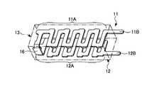
アンテナ装置10は、第1のアンテナエレメント11、第2のアンテナエレメント12、及び封止材13等により構成されている。
The
第1及び第2のアンテナエレメント11,12は、導電性金属板をプレス打加工等を用いて一体的に形成したものである。本実施形態では、上部に位置する第1のアンテナエレメント11はGPS用アンテナであり、下部に位置する第2のアンテナエレメント12はブルートゥース用アンテナである。
The first and
また本実施形態では、第1のアンテナエレメント11と第2のアンテナエレメント12は同一形状とされている。しかしながら、各アンテナエレメント11,12は必ずしも同一形状とする必要はなく、後述するように容量性カップリングが可能であれば異なる形状とすることも可能である。
In the present embodiment, the
また、後述するように第1のアンテナエレメント11と第2のアンテナエレメント12の離間距離が所定値となるように高精度に位置決めする必要がある。このため第1のアンテナエレメント11と第2のアンテナエレメント12との間には連結部16を一体的に形成している。この連結部16により、第1のアンテナエレメント11と第2のアンテナエレメント12の離間距離を一定に保つことができる。
In addition, as will be described later, it is necessary to position the
尚、本実施形態では第1及び第2のアンテナエレメント11,12の材質としてステンレスを用いているが、各アンテナエレメント11,12の材質はこれに限定されるものではなく、銅等の他の材料を用いることも可能である。また、必要に応じて各アンテナエレメント11,12の表面にメッキを施した構成としてもよい。
In this embodiment, stainless steel is used as the material of the first and
また、第1及び第2のアンテナエレメント11,12は、図2に拡大して示すように、メアンダ部11A,12A、給電端子部11B,12B、及び連結部16を一体的に形成している。メアンダ部11A,12Aは、ジグザグのパターンとされた部分である。このように、メアンダ部11A,12Aを形成することにより、アンテナの実質的な長さを長くしつつ、小形化を図ることができる。本実施形態では、アンテナ装置10の外形の大きさを3mm×10mm×3.5mmとすることができた。
The first and
給電端子部11B,12Bはメアンダ部11A,12Bの端部に側方に延出するよう形成されている。図1に示すように、給電端子部11B,12Bは封止材13の外部に延出する部位である。この給電端子部11B,12Bは、携帯端末装置内の電子回路に接続される。尚、本実施形態では、第1及び第2のアンテナエレメント11,12の幅は0.5mm〜2.0mmとしている。
The power
封止材13は、高誘電樹脂材料により形成されている。この本実施形態で使用している高誘電樹脂材料は、例えば液晶ポリマー樹脂(LCP樹脂)に所定のQ値や比誘電率を有するセラミック粉末を添加することにより高誘電特性を調整したものである。このように、封止材13を高誘電樹脂材料とすることにより、波長短縮効果によりアンテナ装置10の小形化を図ることができる。
The sealing
この封止材13の比誘電率は、例えば4以上30以下が望ましい。封止材13の比誘電率をこの範囲に設定することにより、封止材13のアンテナ特性を低下することなく小形化を図ることができる。即ち,比誘電率がA未満になると封止材13の形状を有効に小さくすることが困難となり、逆に比誘電率がBを超えると共振周波数帯域が狭くなりアンテナ特性が低下してしまう。
The relative dielectric constant of the sealing
尚、本実施形態では封止材13が樹脂材にセラミック粉末を添加した構成を例示したが、封止材13の材質はこれに限定されるものではない。上記の比誘電率が実現できる材料であれば、セラミック単体及び樹脂単体からなる封止材を用いることも可能である。
In addition, although the sealing
上記した第1及び第2のアンテナエレメント11,12は、インサート成型により封止材13内に埋設される。図3は、第1及び第2のアンテナエレメント11,12を封止材13内にインサート成型する際に使用する金型20を示している。
The first and
金型20は、上型21と下型22とにより構成されている。上型21には図示しないプランジャーが装着されるポット28が設けられている。上型21は、基台26の上部にホルダベース27が設けられている。ホルダベース27の中央部にはダイブロック23が装着されており、このダイブロック23にはアンテナ装置10の形状に対応したキャビティ24が形成されている。
The
本実施形態では、ダイブロック23に4個のキャビティ24が形成されている。各キャビティ24はランナ25により接続されており、上型21と下型22を組み合わせた状態において、ポット28はランナ25に接続する。尚、位置決め支柱29は、上型21と下型22の位置決めを行うための部材である。
In the present embodiment, four
インサート成型を行うには、先ず第1及び第2のアンテナエレメント11,12をキャビティ24内に装着する。この際、第1のアンテナエレメント11と第2のアンテナエレメント12はキャビティ24内で平行となるよう装着される。また、各アンテナエレメント11,12は、キャビティ24に装着された状態で、キャビティ24の内壁から離間するよう金型20に取り付けられる。
In order to perform insert molding, the first and
上記のように第1及び第2のアンテナエレメント11,12がダイブロック23に装着されると、上型21は下型22に装着される。続いて、ポット28に封止材13となる高誘電樹脂材料が装填されると共に図示しないプランジャーにより樹脂は加圧され、ランナ25を介して各キャビティ24に導入される。これにより、封止材13の内部に第1及び第2のアンテナエレメント11,12が埋設されたアンテナ装置10が製造される。
When the first and
この際、第1のアンテナエレメント11と第2のアンテナエレメント12は連結部16で連結されているため、キャビティ24内に樹脂が充填しても、各アンテナエレメント11,12の離間距離を所定値に保つことができる。
At this time, since the
上記のように、アンテナ装置10はインサート成型法を用いて製造されるため、従来のように基板を積層したりアンテナエレメントをパターン形成したりする方法に比べ、製造設備は少なくて墨、また製造工程も簡単化するため、製造効率の向上及び製造コストの低減を図ることができる。
As described above, the
尚、図4は、各アンテナエレメント14,15の離間距離を所定値に保つ変形例を示している。この変形例では、各アンテナエレメント14,15に脚部14C,15Cを形成した構成としている。この脚部14C,15Cの長さに差を設けておくことにより、各アンテナエレメント14,15の離間距離を所定値に保つことが可能となる。
FIG. 4 shows a modification in which the distance between the
この図4に示す変形例では、第1のアンテナエレメント14にはメアンダ部14Aの端部に一本の脚部14Cのみが設けられた構成とされており、この脚部14Cの下端に給電端子部14Bが形成された構成とされている。また、第2のアンテナエレメント15は、メアンダ部15Aの両端に脚部15Cが設けられており、その一方の脚部15Cに給電端子部15Bが一体的に形成された構成とされている。
In the modification shown in FIG. 4, the
次に、上記のように製造されたアンテナ装置10の構造に注目する。前記のように第1のアンテナエレメント11と第2のアンテナエレメント12は封止材13内で平行状態を維持した状態となっている。また、この一対のアンテナエレメント11,12の間には、高誘電率を有した封止材13が介在した構成となっている。
Next, attention is focused on the structure of the
よって、この一対のアンテナエレメント11,12は、封止材13を介して容量性カップリングされた状態となる。本実施形態に係るアンテナ装置10は、この一対のアンテナエレメント11,12間に発生する容量性キャパシタを利用して二つの周波数帯域で動作するアンテナ装置を実現している。
Therefore, the pair of
即ち、二つのメアンダライン形状のアンテナエレメント11,12の距離を変化させることで、結合容量も変化する。この結合容量と距離との関係を利用して、本実施形態に係るアンテナ装置10では、任意の週数でインピーダンス調整を行っている。
That is, by changing the distance between the two meander
図5は、本実施形態に係るアンテナ装置10のMSWR特性を示している。同図に示すように、アンテナ装置10のGPS帯(約1575MHz)においてVSWRは0.2となっており、またBluetooth帯(約2400MHz)においてVSWRは2.5となっている。よって、小型アンテナ装置として、良好な性能であることが実証された。
FIG. 5 shows the MSWR characteristics of the
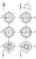
一方、図6はアンテナ装置10の指向性特性を示している。測定方法としはて、同図(G)に示すように、所定形状(例えば、携帯電話に用いられる一般的な基板形状)の基板30にアンテナ装置10を実装し指向性の評価を行った。
On the other hand, FIG. 6 shows the directivity characteristic of the
図12は、図1に示したアンテナ装置10について、アンテナ利得及び放射指向性を測定した結果を示している。また、本測定では二つの伝播周波数について測定している。具体的には特性を測定する周波数として、GPSの周波数に対応する第1の周波数(周波数1)と、ブルートゥースに対応する第2の周波数(周波数2)を設定した。図6(A),(B),(C)は周波数1のX−Y面、Y−Z面、X−Z面の夫々の特性を示し、図6(D),(E),(F)は周波数2のX−Y面、Y−Z面、X−Z面の夫々の特性を示している(X,Y,Zの方向は図6(G)参照)。また、いずれの指向性特性測定においても、垂直偏波成分と水平偏波成分を測定することとした。
FIG. 12 shows the results of measuring the antenna gain and radiation directivity for the
先ず、周波数1の特性に注目すると、X−Y面では垂直偏波の利得が低いものの、水平偏波においては高い利得を有すると共に無指向性であることが分かった。また、Y−Z面及びX−Z面では、垂直偏波及び水平偏波の双方において高利得で無指向性であることが分かった。
First, paying attention to the characteristics of
また、周波数2の特性も周波数1と略同様の特性を示し、X−Y面では垂直偏波の利得が低いものの水平偏波においては高い利得を有すると共に無指向性を有し、Y−Z面及びX−Z面では垂直偏波及び水平偏波の双方において高利得で無指向性であることが分かった。
Further, the characteristics of
従って図6に示す結果より、本実施形態に係るアンテナ装置10は高利得で無指向性に優れたアンテナであることが立証された。
Therefore, the result shown in FIG. 6 proves that the
以上、本発明の好ましい実施形態について詳述したが、本発明は上記した特定の実施形態に限定されるものではなく、特許請求の範囲に記載された本発明の要旨の範囲内において、種々の変形・変更が可能なものである。 The preferred embodiments of the present invention have been described in detail above. However, the present invention is not limited to the specific embodiments described above, and various modifications are possible within the scope of the gist of the present invention described in the claims. It can be modified and changed.
10 アンテナ装置
11,14 第1のアンテナエレメント
12,15 第2のアンテナエレメント
11A,12A,14A,15A メアンダ部
11B,12B,14B,15B 給電端子部
13 封止材
16 連結部
20 金型
24 キャビティ
DESCRIPTION OF
Claims (4)
高誘電材料からなり、前記第1及び第2のアンテナエレメントを封止する封止材とを有しており、
前記第1のアンテナエレメントと前記第2のアンテナエレメントを平行に配置すると共に、
該第1及び第2のアンテナエレメントを前記封止材内にインサート成型により埋設した構成としたことを特徴とするアンテナ装置。 First and second antenna elements formed by forming a conductive metal plate in a meander shape;
It is made of a high dielectric material and has a sealing material for sealing the first and second antenna elements,
While arranging the first antenna element and the second antenna element in parallel,
An antenna device characterized in that the first and second antenna elements are embedded in the sealing material by insert molding.
Priority Applications (5)
| Application Number | Priority Date | Filing Date | Title |
|---|---|---|---|
| JP2011021059A JP2012161041A (en) | 2011-02-02 | 2011-02-02 | Antenna device |
| PCT/JP2012/051078 WO2012105325A1 (en) | 2011-02-02 | 2012-01-19 | Antenna device |
| EP12741655.0A EP2672567A4 (en) | 2011-02-02 | 2012-01-19 | Antenna device |
| CN2012800072210A CN103348530A (en) | 2011-02-02 | 2012-01-19 | Antenna device |
| US13/982,345 US20140232610A1 (en) | 2011-02-02 | 2012-01-19 | Antenna device |
Applications Claiming Priority (1)
| Application Number | Priority Date | Filing Date | Title |
|---|---|---|---|
| JP2011021059A JP2012161041A (en) | 2011-02-02 | 2011-02-02 | Antenna device |
Related Child Applications (1)
| Application Number | Title | Priority Date | Filing Date |
|---|---|---|---|
| JP2014040842A Division JP5702008B2 (en) | 2014-03-03 | 2014-03-03 | Antenna device |
Publications (1)
| Publication Number | Publication Date |
|---|---|
| JP2012161041A true JP2012161041A (en) | 2012-08-23 |
Family
ID=46602544
Family Applications (1)
| Application Number | Title | Priority Date | Filing Date |
|---|---|---|---|
| JP2011021059A Pending JP2012161041A (en) | 2011-02-02 | 2011-02-02 | Antenna device |
Country Status (5)
| Country | Link |
|---|---|
| US (1) | US20140232610A1 (en) |
| EP (1) | EP2672567A4 (en) |
| JP (1) | JP2012161041A (en) |
| CN (1) | CN103348530A (en) |
| WO (1) | WO2012105325A1 (en) |
Families Citing this family (124)
| Publication number | Priority date | Publication date | Assignee | Title |
|---|---|---|---|---|
| US11502551B2 (en) | 2012-07-06 | 2022-11-15 | Energous Corporation | Wirelessly charging multiple wireless-power receivers using different subsets of an antenna array to focus energy at different locations |
| US10090699B1 (en) | 2013-11-01 | 2018-10-02 | Energous Corporation | Wireless powered house |
| US10312715B2 (en) | 2015-09-16 | 2019-06-04 | Energous Corporation | Systems and methods for wireless power charging |
| US10124754B1 (en) | 2013-07-19 | 2018-11-13 | Energous Corporation | Wireless charging and powering of electronic sensors in a vehicle |
| US10103582B2 (en) | 2012-07-06 | 2018-10-16 | Energous Corporation | Transmitters for wireless power transmission |
| US10211674B1 (en) | 2013-06-12 | 2019-02-19 | Energous Corporation | Wireless charging using selected reflectors |
| US20150326070A1 (en) | 2014-05-07 | 2015-11-12 | Energous Corporation | Methods and Systems for Maximum Power Point Transfer in Receivers |
| US10291066B1 (en) | 2014-05-07 | 2019-05-14 | Energous Corporation | Power transmission control systems and methods |
| US10148097B1 (en) | 2013-11-08 | 2018-12-04 | Energous Corporation | Systems and methods for using a predetermined number of communication channels of a wireless power transmitter to communicate with different wireless power receivers |
| US10270261B2 (en) | 2015-09-16 | 2019-04-23 | Energous Corporation | Systems and methods of object detection in wireless power charging systems |
| US10223717B1 (en) | 2014-05-23 | 2019-03-05 | Energous Corporation | Systems and methods for payment-based authorization of wireless power transmission service |
| US10186913B2 (en) | 2012-07-06 | 2019-01-22 | Energous Corporation | System and methods for pocket-forming based on constructive and destructive interferences to power one or more wireless power receivers using a wireless power transmitter including a plurality of antennas |
| US9867062B1 (en) | 2014-07-21 | 2018-01-09 | Energous Corporation | System and methods for using a remote server to authorize a receiving device that has requested wireless power and to determine whether another receiving device should request wireless power in a wireless power transmission system |
| US9438045B1 (en) | 2013-05-10 | 2016-09-06 | Energous Corporation | Methods and systems for maximum power point transfer in receivers |
| US10381880B2 (en) | 2014-07-21 | 2019-08-13 | Energous Corporation | Integrated antenna structure arrays for wireless power transmission |
| US10230266B1 (en) | 2014-02-06 | 2019-03-12 | Energous Corporation | Wireless power receivers that communicate status data indicating wireless power transmission effectiveness with a transmitter using a built-in communications component of a mobile device, and methods of use thereof |
| US10211682B2 (en) | 2014-05-07 | 2019-02-19 | Energous Corporation | Systems and methods for controlling operation of a transmitter of a wireless power network based on user instructions received from an authenticated computing device powered or charged by a receiver of the wireless power network |
| US10205239B1 (en) | 2014-05-07 | 2019-02-12 | Energous Corporation | Compact PIFA antenna |
| US9853458B1 (en) | 2014-05-07 | 2017-12-26 | Energous Corporation | Systems and methods for device and power receiver pairing |
| US10291055B1 (en) | 2014-12-29 | 2019-05-14 | Energous Corporation | Systems and methods for controlling far-field wireless power transmission based on battery power levels of a receiving device |
| US10256657B2 (en) | 2015-12-24 | 2019-04-09 | Energous Corporation | Antenna having coaxial structure for near field wireless power charging |
| US10038337B1 (en) | 2013-09-16 | 2018-07-31 | Energous Corporation | Wireless power supply for rescue devices |
| US9887584B1 (en) | 2014-08-21 | 2018-02-06 | Energous Corporation | Systems and methods for a configuration web service to provide configuration of a wireless power transmitter within a wireless power transmission system |
| US10193396B1 (en) | 2014-05-07 | 2019-01-29 | Energous Corporation | Cluster management of transmitters in a wireless power transmission system |
| US9871398B1 (en) | 2013-07-01 | 2018-01-16 | Energous Corporation | Hybrid charging method for wireless power transmission based on pocket-forming |
| US10199849B1 (en) | 2014-08-21 | 2019-02-05 | Energous Corporation | Method for automatically testing the operational status of a wireless power receiver in a wireless power transmission system |
| US10128699B2 (en) | 2014-07-14 | 2018-11-13 | Energous Corporation | Systems and methods of providing wireless power using receiver device sensor inputs |
| US10199835B2 (en) | 2015-12-29 | 2019-02-05 | Energous Corporation | Radar motion detection using stepped frequency in wireless power transmission system |
| US9825674B1 (en) | 2014-05-23 | 2017-11-21 | Energous Corporation | Enhanced transmitter that selects configurations of antenna elements for performing wireless power transmission and receiving functions |
| US10243414B1 (en) | 2014-05-07 | 2019-03-26 | Energous Corporation | Wearable device with wireless power and payload receiver |
| US12057715B2 (en) | 2012-07-06 | 2024-08-06 | Energous Corporation | Systems and methods of wirelessly delivering power to a wireless-power receiver device in response to a change of orientation of the wireless-power receiver device |
| US10992187B2 (en) | 2012-07-06 | 2021-04-27 | Energous Corporation | System and methods of using electromagnetic waves to wirelessly deliver power to electronic devices |
| US9124125B2 (en) | 2013-05-10 | 2015-09-01 | Energous Corporation | Wireless power transmission with selective range |
| US10141791B2 (en) | 2014-05-07 | 2018-11-27 | Energous Corporation | Systems and methods for controlling communications during wireless transmission of power using application programming interfaces |
| US10063105B2 (en) | 2013-07-11 | 2018-08-28 | Energous Corporation | Proximity transmitters for wireless power charging systems |
| US10206185B2 (en) | 2013-05-10 | 2019-02-12 | Energous Corporation | System and methods for wireless power transmission to an electronic device in accordance with user-defined restrictions |
| US9843201B1 (en) | 2012-07-06 | 2017-12-12 | Energous Corporation | Wireless power transmitter that selects antenna sets for transmitting wireless power to a receiver based on location of the receiver, and methods of use thereof |
| US10263432B1 (en) | 2013-06-25 | 2019-04-16 | Energous Corporation | Multi-mode transmitter with an antenna array for delivering wireless power and providing Wi-Fi access |
| US9859797B1 (en) | 2014-05-07 | 2018-01-02 | Energous Corporation | Synchronous rectifier design for wireless power receiver |
| US10992185B2 (en) | 2012-07-06 | 2021-04-27 | Energous Corporation | Systems and methods of using electromagnetic waves to wirelessly deliver power to game controllers |
| US10439448B2 (en) | 2014-08-21 | 2019-10-08 | Energous Corporation | Systems and methods for automatically testing the communication between wireless power transmitter and wireless power receiver |
| US10224758B2 (en) | 2013-05-10 | 2019-03-05 | Energous Corporation | Wireless powering of electronic devices with selective delivery range |
| US10965164B2 (en) | 2012-07-06 | 2021-03-30 | Energous Corporation | Systems and methods of wirelessly delivering power to a receiver device |
| US9812890B1 (en) | 2013-07-11 | 2017-11-07 | Energous Corporation | Portable wireless charging pad |
| US9876394B1 (en) | 2014-05-07 | 2018-01-23 | Energous Corporation | Boost-charger-boost system for enhanced power delivery |
| US10211680B2 (en) | 2013-07-19 | 2019-02-19 | Energous Corporation | Method for 3 dimensional pocket-forming |
| US10141768B2 (en) | 2013-06-03 | 2018-11-27 | Energous Corporation | Systems and methods for maximizing wireless power transfer efficiency by instructing a user to change a receiver device's position |
| US10008889B2 (en) | 2014-08-21 | 2018-06-26 | Energous Corporation | Method for automatically testing the operational status of a wireless power receiver in a wireless power transmission system |
| US10063106B2 (en) | 2014-05-23 | 2018-08-28 | Energous Corporation | System and method for a self-system analysis in a wireless power transmission network |
| US10090886B1 (en) | 2014-07-14 | 2018-10-02 | Energous Corporation | System and method for enabling automatic charging schedules in a wireless power network to one or more devices |
| US10128693B2 (en) | 2014-07-14 | 2018-11-13 | Energous Corporation | System and method for providing health safety in a wireless power transmission system |
| US9787103B1 (en) | 2013-08-06 | 2017-10-10 | Energous Corporation | Systems and methods for wirelessly delivering power to electronic devices that are unable to communicate with a transmitter |
| US10218227B2 (en) | 2014-05-07 | 2019-02-26 | Energous Corporation | Compact PIFA antenna |
| US10063064B1 (en) | 2014-05-23 | 2018-08-28 | Energous Corporation | System and method for generating a power receiver identifier in a wireless power network |
| US10103552B1 (en) | 2013-06-03 | 2018-10-16 | Energous Corporation | Protocols for authenticated wireless power transmission |
| KR101481287B1 (en) * | 2013-07-01 | 2015-01-14 | 현대자동차주식회사 | Vehicle antenna for mobile service |
| US10021523B2 (en) | 2013-07-11 | 2018-07-10 | Energous Corporation | Proximity transmitters for wireless power charging systems |
| US10075017B2 (en) | 2014-02-06 | 2018-09-11 | Energous Corporation | External or internal wireless power receiver with spaced-apart antenna elements for charging or powering mobile devices using wirelessly delivered power |
| US10158257B2 (en) | 2014-05-01 | 2018-12-18 | Energous Corporation | System and methods for using sound waves to wirelessly deliver power to electronic devices |
| US10153645B1 (en) | 2014-05-07 | 2018-12-11 | Energous Corporation | Systems and methods for designating a master power transmitter in a cluster of wireless power transmitters |
| US10170917B1 (en) | 2014-05-07 | 2019-01-01 | Energous Corporation | Systems and methods for managing and controlling a wireless power network by establishing time intervals during which receivers communicate with a transmitter |
| US10153653B1 (en) | 2014-05-07 | 2018-12-11 | Energous Corporation | Systems and methods for using application programming interfaces to control communications between a transmitter and a receiver |
| US10068703B1 (en) | 2014-07-21 | 2018-09-04 | Energous Corporation | Integrated miniature PIFA with artificial magnetic conductor metamaterials |
| US10116143B1 (en) | 2014-07-21 | 2018-10-30 | Energous Corporation | Integrated antenna arrays for wireless power transmission |
| US10122415B2 (en) | 2014-12-27 | 2018-11-06 | Energous Corporation | Systems and methods for assigning a set of antennas of a wireless power transmitter to a wireless power receiver based on a location of the wireless power receiver |
| DE102015208845B3 (en) * | 2015-05-13 | 2016-08-11 | Sivantos Pte. Ltd. | hearing Aid |
| US10523033B2 (en) | 2015-09-15 | 2019-12-31 | Energous Corporation | Receiver devices configured to determine location within a transmission field |
| US10199850B2 (en) | 2015-09-16 | 2019-02-05 | Energous Corporation | Systems and methods for wirelessly transmitting power from a transmitter to a receiver by determining refined locations of the receiver in a segmented transmission field associated with the transmitter |
| US10158259B1 (en) | 2015-09-16 | 2018-12-18 | Energous Corporation | Systems and methods for identifying receivers in a transmission field by transmitting exploratory power waves towards different segments of a transmission field |
| US10008875B1 (en) | 2015-09-16 | 2018-06-26 | Energous Corporation | Wireless power transmitter configured to transmit power waves to a predicted location of a moving wireless power receiver |
| US10211685B2 (en) | 2015-09-16 | 2019-02-19 | Energous Corporation | Systems and methods for real or near real time wireless communications between a wireless power transmitter and a wireless power receiver |
| US9871387B1 (en) | 2015-09-16 | 2018-01-16 | Energous Corporation | Systems and methods of object detection using one or more video cameras in wireless power charging systems |
| US11710321B2 (en) | 2015-09-16 | 2023-07-25 | Energous Corporation | Systems and methods of object detection in wireless power charging systems |
| US10186893B2 (en) | 2015-09-16 | 2019-01-22 | Energous Corporation | Systems and methods for real time or near real time wireless communications between a wireless power transmitter and a wireless power receiver |
| US10778041B2 (en) | 2015-09-16 | 2020-09-15 | Energous Corporation | Systems and methods for generating power waves in a wireless power transmission system |
| US10153660B1 (en) | 2015-09-22 | 2018-12-11 | Energous Corporation | Systems and methods for preconfiguring sensor data for wireless charging systems |
| US10050470B1 (en) | 2015-09-22 | 2018-08-14 | Energous Corporation | Wireless power transmission device having antennas oriented in three dimensions |
| US10027168B2 (en) | 2015-09-22 | 2018-07-17 | Energous Corporation | Systems and methods for generating and transmitting wireless power transmission waves using antennas having a spacing that is selected by the transmitter |
| US10135295B2 (en) | 2015-09-22 | 2018-11-20 | Energous Corporation | Systems and methods for nullifying energy levels for wireless power transmission waves |
| US10033222B1 (en) | 2015-09-22 | 2018-07-24 | Energous Corporation | Systems and methods for determining and generating a waveform for wireless power transmission waves |
| US10128686B1 (en) | 2015-09-22 | 2018-11-13 | Energous Corporation | Systems and methods for identifying receiver locations using sensor technologies |
| US10135294B1 (en) | 2015-09-22 | 2018-11-20 | Energous Corporation | Systems and methods for preconfiguring transmission devices for power wave transmissions based on location data of one or more receivers |
| US10020678B1 (en) | 2015-09-22 | 2018-07-10 | Energous Corporation | Systems and methods for selecting antennas to generate and transmit power transmission waves |
| US10333332B1 (en) | 2015-10-13 | 2019-06-25 | Energous Corporation | Cross-polarized dipole antenna |
| US10734717B2 (en) | 2015-10-13 | 2020-08-04 | Energous Corporation | 3D ceramic mold antenna |
| US9853485B2 (en) | 2015-10-28 | 2017-12-26 | Energous Corporation | Antenna for wireless charging systems |
| US10063108B1 (en) * | 2015-11-02 | 2018-08-28 | Energous Corporation | Stamped three-dimensional antenna |
| US10135112B1 (en) | 2015-11-02 | 2018-11-20 | Energous Corporation | 3D antenna mount |
| US10027180B1 (en) | 2015-11-02 | 2018-07-17 | Energous Corporation | 3D triple linear antenna that acts as heat sink |
| US10038332B1 (en) | 2015-12-24 | 2018-07-31 | Energous Corporation | Systems and methods of wireless power charging through multiple receiving devices |
| US10256677B2 (en) | 2016-12-12 | 2019-04-09 | Energous Corporation | Near-field RF charging pad with adaptive loading to efficiently charge an electronic device at any position on the pad |
| US10320446B2 (en) | 2015-12-24 | 2019-06-11 | Energous Corporation | Miniaturized highly-efficient designs for near-field power transfer system |
| US10027159B2 (en) | 2015-12-24 | 2018-07-17 | Energous Corporation | Antenna for transmitting wireless power signals |
| US10116162B2 (en) | 2015-12-24 | 2018-10-30 | Energous Corporation | Near field transmitters with harmonic filters for wireless power charging |
| US11863001B2 (en) | 2015-12-24 | 2024-01-02 | Energous Corporation | Near-field antenna for wireless power transmission with antenna elements that follow meandering patterns |
| US10079515B2 (en) | 2016-12-12 | 2018-09-18 | Energous Corporation | Near-field RF charging pad with multi-band antenna element with adaptive loading to efficiently charge an electronic device at any position on the pad |
| US10164478B2 (en) | 2015-12-29 | 2018-12-25 | Energous Corporation | Modular antenna boards in wireless power transmission systems |
| US10923954B2 (en) | 2016-11-03 | 2021-02-16 | Energous Corporation | Wireless power receiver with a synchronous rectifier |
| KR102185600B1 (en) | 2016-12-12 | 2020-12-03 | 에너저스 코포레이션 | A method of selectively activating antenna zones of a near field charging pad to maximize transmitted wireless power |
| US10680319B2 (en) | 2017-01-06 | 2020-06-09 | Energous Corporation | Devices and methods for reducing mutual coupling effects in wireless power transmission systems |
| US10439442B2 (en) | 2017-01-24 | 2019-10-08 | Energous Corporation | Microstrip antennas for wireless power transmitters |
| US10389161B2 (en) | 2017-03-15 | 2019-08-20 | Energous Corporation | Surface mount dielectric antennas for wireless power transmitters |
| US11011942B2 (en) | 2017-03-30 | 2021-05-18 | Energous Corporation | Flat antennas having two or more resonant frequencies for use in wireless power transmission systems |
| US10511097B2 (en) | 2017-05-12 | 2019-12-17 | Energous Corporation | Near-field antennas for accumulating energy at a near-field distance with minimal far-field gain |
| US11462949B2 (en) | 2017-05-16 | 2022-10-04 | Wireless electrical Grid LAN, WiGL Inc | Wireless charging method and system |
| US12074452B2 (en) | 2017-05-16 | 2024-08-27 | Wireless Electrical Grid Lan, Wigl Inc. | Networked wireless charging system |
| US12074460B2 (en) | 2017-05-16 | 2024-08-27 | Wireless Electrical Grid Lan, Wigl Inc. | Rechargeable wireless power bank and method of using |
| US10848853B2 (en) | 2017-06-23 | 2020-11-24 | Energous Corporation | Systems, methods, and devices for utilizing a wire of a sound-producing device as an antenna for receipt of wirelessly delivered power |
| US10122219B1 (en) | 2017-10-10 | 2018-11-06 | Energous Corporation | Systems, methods, and devices for using a battery as a antenna for receiving wirelessly delivered power from radio frequency power waves |
| US11342798B2 (en) | 2017-10-30 | 2022-05-24 | Energous Corporation | Systems and methods for managing coexistence of wireless-power signals and data signals operating in a same frequency band |
| US10615647B2 (en) | 2018-02-02 | 2020-04-07 | Energous Corporation | Systems and methods for detecting wireless power receivers and other objects at a near-field charging pad |
| US11159057B2 (en) | 2018-03-14 | 2021-10-26 | Energous Corporation | Loop antennas with selectively-activated feeds to control propagation patterns of wireless power signals |
| US11515732B2 (en) | 2018-06-25 | 2022-11-29 | Energous Corporation | Power wave transmission techniques to focus wirelessly delivered power at a receiving device |
| US11437735B2 (en) | 2018-11-14 | 2022-09-06 | Energous Corporation | Systems for receiving electromagnetic energy using antennas that are minimally affected by the presence of the human body |
| WO2020160015A1 (en) | 2019-01-28 | 2020-08-06 | Energous Corporation | Systems and methods for miniaturized antenna for wireless power transmissions |
| KR20210123329A (en) | 2019-02-06 | 2021-10-13 | 에너저스 코포레이션 | System and method for estimating optimal phase for use with individual antennas in an antenna array |
| WO2021055900A1 (en) | 2019-09-20 | 2021-03-25 | Energous Corporation | Classifying and detecting foreign objects using a power amplifier controller integrated circuit in wireless power transmission systems |
| WO2021055898A1 (en) | 2019-09-20 | 2021-03-25 | Energous Corporation | Systems and methods for machine learning based foreign object detection for wireless power transmission |
| CN115104234A (en) | 2019-09-20 | 2022-09-23 | 艾诺格思公司 | System and method for protecting a wireless power receiver using multiple rectifiers and establishing in-band communication using multiple rectifiers |
| US11381118B2 (en) | 2019-09-20 | 2022-07-05 | Energous Corporation | Systems and methods for machine learning based foreign object detection for wireless power transmission |
| US11355966B2 (en) | 2019-12-13 | 2022-06-07 | Energous Corporation | Charging pad with guiding contours to align an electronic device on the charging pad and efficiently transfer near-field radio-frequency energy to the electronic device |
| US10985617B1 (en) | 2019-12-31 | 2021-04-20 | Energous Corporation | System for wirelessly transmitting energy at a near-field distance without using beam-forming control |
| US11799324B2 (en) | 2020-04-13 | 2023-10-24 | Energous Corporation | Wireless-power transmitting device for creating a uniform near-field charging area |
| US11916398B2 (en) | 2021-12-29 | 2024-02-27 | Energous Corporation | Small form-factor devices with integrated and modular harvesting receivers, and shelving-mounted wireless-power transmitters for use therewith |
Citations (3)
| Publication number | Priority date | Publication date | Assignee | Title |
|---|---|---|---|---|
| JP2001217632A (en) * | 2000-01-31 | 2001-08-10 | Matsushita Electric Ind Co Ltd | Antenna and electronic equipment |
| JP2007013981A (en) * | 2005-06-30 | 2007-01-18 | Samsung Electro Mech Co Ltd | Internal chip antenna |
| JP2007049674A (en) * | 2005-03-24 | 2007-02-22 | Tdk Corp | Antenna structure |
Family Cites Families (9)
| Publication number | Priority date | Publication date | Assignee | Title |
|---|---|---|---|---|
| JP2000022421A (en) * | 1998-07-03 | 2000-01-21 | Murata Mfg Co Ltd | Chip antenna and radio device mounted with it |
| TW513829B (en) * | 2000-10-12 | 2002-12-11 | Furukawa Electric Co Ltd | Small antenna |
| GB0030741D0 (en) * | 2000-12-16 | 2001-01-31 | Koninkl Philips Electronics Nv | Antenna arrangement |
| KR100444218B1 (en) | 2001-09-25 | 2004-08-16 | 삼성전기주식회사 | Dual feeding chip antenna for providing diversity |
| JP2003209432A (en) * | 2001-11-08 | 2003-07-25 | Furukawa Electric Co Ltd:The | Miniaturized antenna |
| JP2004228982A (en) | 2003-01-23 | 2004-08-12 | Alps Electric Co Ltd | Dual band antenna |
| JP3895737B2 (en) * | 2004-04-09 | 2007-03-22 | 古河電気工業株式会社 | Multi-frequency antenna and small antenna |
| CN101675557B (en) * | 2007-05-02 | 2013-03-13 | 株式会社村田制作所 | Antenna structure and wireless communication apparatus comprising the same |
| JP5008602B2 (en) * | 2008-05-09 | 2012-08-22 | 株式会社フジクラ | antenna |
-
2011
- 2011-02-02 JP JP2011021059A patent/JP2012161041A/en active Pending
-
2012
- 2012-01-19 US US13/982,345 patent/US20140232610A1/en not_active Abandoned
- 2012-01-19 CN CN2012800072210A patent/CN103348530A/en active Pending
- 2012-01-19 EP EP12741655.0A patent/EP2672567A4/en not_active Withdrawn
- 2012-01-19 WO PCT/JP2012/051078 patent/WO2012105325A1/en active Application Filing
Patent Citations (3)
| Publication number | Priority date | Publication date | Assignee | Title |
|---|---|---|---|---|
| JP2001217632A (en) * | 2000-01-31 | 2001-08-10 | Matsushita Electric Ind Co Ltd | Antenna and electronic equipment |
| JP2007049674A (en) * | 2005-03-24 | 2007-02-22 | Tdk Corp | Antenna structure |
| JP2007013981A (en) * | 2005-06-30 | 2007-01-18 | Samsung Electro Mech Co Ltd | Internal chip antenna |
Also Published As
| Publication number | Publication date |
|---|---|
| EP2672567A4 (en) | 2014-07-09 |
| CN103348530A (en) | 2013-10-09 |
| WO2012105325A1 (en) | 2012-08-09 |
| EP2672567A1 (en) | 2013-12-11 |
| US20140232610A1 (en) | 2014-08-21 |
Similar Documents
| Publication | Publication Date | Title |
|---|---|---|
| JP2012161041A (en) | Antenna device | |
| US10707558B2 (en) | Electronic device antenna with embedded parasitic arm | |
| US10749246B2 (en) | Wireless handheld devices, radiation systems and manufacturing methods | |
| AU2016100421B4 (en) | Electronic device with peripheral hybrid antenna | |
| EP2375489A2 (en) | Mobile wireless terminal and antenna device | |
| JP2004088218A (en) | Planar antenna | |
| KR101505595B1 (en) | Microstrip chip antenna with top loading structure | |
| JP2006517370A (en) | Planar high frequency or microwave antenna | |
| KR20090033372A (en) | Antenna component and assembly | |
| JP2005094360A (en) | Antenna device and radio communication apparatus | |
| TWI403021B (en) | Carrier and device | |
| JP2012235258A (en) | Portable radio apparatus | |
| EP2323223A1 (en) | Chip antenna | |
| JP2008042600A (en) | Antenna system | |
| KR100691237B1 (en) | Multi-band chip antenna | |
| JP5702008B2 (en) | Antenna device | |
| TWI612722B (en) | Lte multiband monopole antenna used in electronic appliance having metal frame | |
| KR101970861B1 (en) | Antenna device | |
| JP6527865B2 (en) | Device for transmitting and receiving radio frequency signals | |
| KR100962574B1 (en) | Chip antenna for adjusting resonance frequency by via hole | |
| TWI488359B (en) | Communication electronic device and antenna element thereof | |
| TW200832813A (en) | Multi-frequency antenna | |
| WO2020151807A1 (en) | Slot antenna and electronic device comprising said slot antenna | |
| CN103904418A (en) | Omnidirectional terminal antenna | |
| JP2004297534A (en) | Electronic element |
Legal Events
| Date | Code | Title | Description |
|---|---|---|---|
| A131 | Notification of reasons for refusal |
Free format text: JAPANESE INTERMEDIATE CODE: A131 Effective date: 20130528 |
|
| A521 | Request for written amendment filed |
Free format text: JAPANESE INTERMEDIATE CODE: A523 Effective date: 20130729 |
|
| A131 | Notification of reasons for refusal |
Free format text: JAPANESE INTERMEDIATE CODE: A131 Effective date: 20130827 |
|
| A521 | Request for written amendment filed |
Free format text: JAPANESE INTERMEDIATE CODE: A523 Effective date: 20131025 |
|
| A02 | Decision of refusal |
Free format text: JAPANESE INTERMEDIATE CODE: A02 Effective date: 20131203 |