EP3394529B1 - Eismaschine mit einem zweikreisverdampfer für kohlenwasserstoffkältemittel - Google Patents
Eismaschine mit einem zweikreisverdampfer für kohlenwasserstoffkältemittel Download PDFInfo
- Publication number
- EP3394529B1 EP3394529B1 EP16880020.9A EP16880020A EP3394529B1 EP 3394529 B1 EP3394529 B1 EP 3394529B1 EP 16880020 A EP16880020 A EP 16880020A EP 3394529 B1 EP3394529 B1 EP 3394529B1
- Authority
- EP
- European Patent Office
- Prior art keywords
- refrigerant
- water
- ice
- ice making
- making assembly
- Prior art date
- Legal status (The legal status is an assumption and is not a legal conclusion. Google has not performed a legal analysis and makes no representation as to the accuracy of the status listed.)
- Active
Links
Images


Classifications
-
- F—MECHANICAL ENGINEERING; LIGHTING; HEATING; WEAPONS; BLASTING
- F25—REFRIGERATION OR COOLING; COMBINED HEATING AND REFRIGERATION SYSTEMS; HEAT PUMP SYSTEMS; MANUFACTURE OR STORAGE OF ICE; LIQUEFACTION SOLIDIFICATION OF GASES
- F25C—PRODUCING, WORKING OR HANDLING ICE
- F25C1/00—Producing ice
- F25C1/22—Construction of moulds; Filling devices for moulds
- F25C1/25—Filling devices for moulds
-
- F—MECHANICAL ENGINEERING; LIGHTING; HEATING; WEAPONS; BLASTING
- F25—REFRIGERATION OR COOLING; COMBINED HEATING AND REFRIGERATION SYSTEMS; HEAT PUMP SYSTEMS; MANUFACTURE OR STORAGE OF ICE; LIQUEFACTION SOLIDIFICATION OF GASES
- F25B—REFRIGERATION MACHINES, PLANTS OR SYSTEMS; COMBINED HEATING AND REFRIGERATION SYSTEMS; HEAT PUMP SYSTEMS
- F25B39/00—Evaporators; Condensers
- F25B39/02—Evaporators
-
- F—MECHANICAL ENGINEERING; LIGHTING; HEATING; WEAPONS; BLASTING
- F25—REFRIGERATION OR COOLING; COMBINED HEATING AND REFRIGERATION SYSTEMS; HEAT PUMP SYSTEMS; MANUFACTURE OR STORAGE OF ICE; LIQUEFACTION SOLIDIFICATION OF GASES
- F25B—REFRIGERATION MACHINES, PLANTS OR SYSTEMS; COMBINED HEATING AND REFRIGERATION SYSTEMS; HEAT PUMP SYSTEMS
- F25B47/00—Arrangements for preventing or removing deposits or corrosion, not provided for in another subclass
- F25B47/02—Defrosting cycles
- F25B47/022—Defrosting cycles hot gas defrosting
-
- F—MECHANICAL ENGINEERING; LIGHTING; HEATING; WEAPONS; BLASTING
- F25—REFRIGERATION OR COOLING; COMBINED HEATING AND REFRIGERATION SYSTEMS; HEAT PUMP SYSTEMS; MANUFACTURE OR STORAGE OF ICE; LIQUEFACTION SOLIDIFICATION OF GASES
- F25C—PRODUCING, WORKING OR HANDLING ICE
- F25C1/00—Producing ice
- F25C1/12—Producing ice by freezing water on cooled surfaces, e.g. to form slabs
-
- F—MECHANICAL ENGINEERING; LIGHTING; HEATING; WEAPONS; BLASTING
- F28—HEAT EXCHANGE IN GENERAL
- F28D—HEAT-EXCHANGE APPARATUS, NOT PROVIDED FOR IN ANOTHER SUBCLASS, IN WHICH THE HEAT-EXCHANGE MEDIA DO NOT COME INTO DIRECT CONTACT
- F28D1/00—Heat-exchange apparatus having stationary conduit assemblies for one heat-exchange medium only, the media being in contact with different sides of the conduit wall, in which the other heat-exchange medium is a large body of fluid, e.g. domestic or motor car radiators
- F28D1/02—Heat-exchange apparatus having stationary conduit assemblies for one heat-exchange medium only, the media being in contact with different sides of the conduit wall, in which the other heat-exchange medium is a large body of fluid, e.g. domestic or motor car radiators with heat-exchange conduits immersed in the body of fluid
- F28D1/04—Heat-exchange apparatus having stationary conduit assemblies for one heat-exchange medium only, the media being in contact with different sides of the conduit wall, in which the other heat-exchange medium is a large body of fluid, e.g. domestic or motor car radiators with heat-exchange conduits immersed in the body of fluid with tubular conduits
- F28D1/047—Heat-exchange apparatus having stationary conduit assemblies for one heat-exchange medium only, the media being in contact with different sides of the conduit wall, in which the other heat-exchange medium is a large body of fluid, e.g. domestic or motor car radiators with heat-exchange conduits immersed in the body of fluid with tubular conduits the conduits being bent, e.g. in a serpentine or zig-zag
- F28D1/0477—Heat-exchange apparatus having stationary conduit assemblies for one heat-exchange medium only, the media being in contact with different sides of the conduit wall, in which the other heat-exchange medium is a large body of fluid, e.g. domestic or motor car radiators with heat-exchange conduits immersed in the body of fluid with tubular conduits the conduits being bent, e.g. in a serpentine or zig-zag the conduits being bent in a serpentine or zig-zag
-
- F—MECHANICAL ENGINEERING; LIGHTING; HEATING; WEAPONS; BLASTING
- F25—REFRIGERATION OR COOLING; COMBINED HEATING AND REFRIGERATION SYSTEMS; HEAT PUMP SYSTEMS; MANUFACTURE OR STORAGE OF ICE; LIQUEFACTION SOLIDIFICATION OF GASES
- F25B—REFRIGERATION MACHINES, PLANTS OR SYSTEMS; COMBINED HEATING AND REFRIGERATION SYSTEMS; HEAT PUMP SYSTEMS
- F25B2339/00—Details of evaporators; Details of condensers
- F25B2339/02—Details of evaporators
- F25B2339/023—Evaporators consisting of one or several sheets on one face of which is fixed a refrigerant carrying coil
-
- F—MECHANICAL ENGINEERING; LIGHTING; HEATING; WEAPONS; BLASTING
- F25—REFRIGERATION OR COOLING; COMBINED HEATING AND REFRIGERATION SYSTEMS; HEAT PUMP SYSTEMS; MANUFACTURE OR STORAGE OF ICE; LIQUEFACTION SOLIDIFICATION OF GASES
- F25B—REFRIGERATION MACHINES, PLANTS OR SYSTEMS; COMBINED HEATING AND REFRIGERATION SYSTEMS; HEAT PUMP SYSTEMS
- F25B2400/00—General features or devices for refrigeration machines, plants or systems, combined heating and refrigeration systems or heat-pump systems, i.e. not limited to a particular subgroup of F25B
- F25B2400/06—Several compression cycles arranged in parallel
-
- F—MECHANICAL ENGINEERING; LIGHTING; HEATING; WEAPONS; BLASTING
- F25—REFRIGERATION OR COOLING; COMBINED HEATING AND REFRIGERATION SYSTEMS; HEAT PUMP SYSTEMS; MANUFACTURE OR STORAGE OF ICE; LIQUEFACTION SOLIDIFICATION OF GASES
- F25B—REFRIGERATION MACHINES, PLANTS OR SYSTEMS; COMBINED HEATING AND REFRIGERATION SYSTEMS; HEAT PUMP SYSTEMS
- F25B2400/00—General features or devices for refrigeration machines, plants or systems, combined heating and refrigeration systems or heat-pump systems, i.e. not limited to a particular subgroup of F25B
- F25B2400/12—Inflammable refrigerants
-
- F—MECHANICAL ENGINEERING; LIGHTING; HEATING; WEAPONS; BLASTING
- F25—REFRIGERATION OR COOLING; COMBINED HEATING AND REFRIGERATION SYSTEMS; HEAT PUMP SYSTEMS; MANUFACTURE OR STORAGE OF ICE; LIQUEFACTION SOLIDIFICATION OF GASES
- F25B—REFRIGERATION MACHINES, PLANTS OR SYSTEMS; COMBINED HEATING AND REFRIGERATION SYSTEMS; HEAT PUMP SYSTEMS
- F25B25/00—Machines, plants or systems, using a combination of modes of operation covered by two or more of the groups F25B1/00 - F25B23/00
- F25B25/005—Machines, plants or systems, using a combination of modes of operation covered by two or more of the groups F25B1/00 - F25B23/00 using primary and secondary systems
-
- F—MECHANICAL ENGINEERING; LIGHTING; HEATING; WEAPONS; BLASTING
- F25—REFRIGERATION OR COOLING; COMBINED HEATING AND REFRIGERATION SYSTEMS; HEAT PUMP SYSTEMS; MANUFACTURE OR STORAGE OF ICE; LIQUEFACTION SOLIDIFICATION OF GASES
- F25B—REFRIGERATION MACHINES, PLANTS OR SYSTEMS; COMBINED HEATING AND REFRIGERATION SYSTEMS; HEAT PUMP SYSTEMS
- F25B40/00—Subcoolers, desuperheaters or superheaters
-
- F—MECHANICAL ENGINEERING; LIGHTING; HEATING; WEAPONS; BLASTING
- F25—REFRIGERATION OR COOLING; COMBINED HEATING AND REFRIGERATION SYSTEMS; HEAT PUMP SYSTEMS; MANUFACTURE OR STORAGE OF ICE; LIQUEFACTION SOLIDIFICATION OF GASES
- F25B—REFRIGERATION MACHINES, PLANTS OR SYSTEMS; COMBINED HEATING AND REFRIGERATION SYSTEMS; HEAT PUMP SYSTEMS
- F25B5/00—Compression machines, plants or systems, with several evaporator circuits, e.g. for varying refrigerating capacity
- F25B5/02—Compression machines, plants or systems, with several evaporator circuits, e.g. for varying refrigerating capacity arranged in parallel
-
- F—MECHANICAL ENGINEERING; LIGHTING; HEATING; WEAPONS; BLASTING
- F25—REFRIGERATION OR COOLING; COMBINED HEATING AND REFRIGERATION SYSTEMS; HEAT PUMP SYSTEMS; MANUFACTURE OR STORAGE OF ICE; LIQUEFACTION SOLIDIFICATION OF GASES
- F25B—REFRIGERATION MACHINES, PLANTS OR SYSTEMS; COMBINED HEATING AND REFRIGERATION SYSTEMS; HEAT PUMP SYSTEMS
- F25B6/00—Compression machines, plants or systems, with several condenser circuits
- F25B6/02—Compression machines, plants or systems, with several condenser circuits arranged in parallel
-
- F—MECHANICAL ENGINEERING; LIGHTING; HEATING; WEAPONS; BLASTING
- F25—REFRIGERATION OR COOLING; COMBINED HEATING AND REFRIGERATION SYSTEMS; HEAT PUMP SYSTEMS; MANUFACTURE OR STORAGE OF ICE; LIQUEFACTION SOLIDIFICATION OF GASES
- F25C—PRODUCING, WORKING OR HANDLING ICE
- F25C2400/00—Auxiliary features or devices for producing, working or handling ice
- F25C2400/10—Refrigerator units
-
- F—MECHANICAL ENGINEERING; LIGHTING; HEATING; WEAPONS; BLASTING
- F25—REFRIGERATION OR COOLING; COMBINED HEATING AND REFRIGERATION SYSTEMS; HEAT PUMP SYSTEMS; MANUFACTURE OR STORAGE OF ICE; LIQUEFACTION SOLIDIFICATION OF GASES
- F25C—PRODUCING, WORKING OR HANDLING ICE
- F25C2600/00—Control issues
- F25C2600/04—Control means
-
- F—MECHANICAL ENGINEERING; LIGHTING; HEATING; WEAPONS; BLASTING
- F28—HEAT EXCHANGE IN GENERAL
- F28F—DETAILS OF HEAT-EXCHANGE AND HEAT-TRANSFER APPARATUS, OF GENERAL APPLICATION
- F28F2210/00—Heat exchange conduits
- F28F2210/10—Particular layout, e.g. for uniform temperature distribution
Definitions
- This invention relates generally to automatic ice making machines and, more specifically, to ice making machines using hydrocarbon refrigerants, such as propane, with a unique evaporator comprising of a single freeze plate attached to dual, independent refrigerant circuits that are designed in such a way as to ensure the even production of ice across the evaporator, thus allowing an increased ice production capacity within the allowable limit of system charge.
- hydrocarbon refrigerants such as propane
- Ice making machines are employed in commercial and residential applications around the world.
- ice makers In domestic applications, ice makers are typically located in a freezer compartment. The resulting ice is usually of poor quality due to the trapping of air and impurities during the freezing process.
- the ice makers In commercial applications, the ice makers typically freeze the ice upright, or vertically, in a manner that removes the impurities and creates pure, clear ice cubes.
- U.S. Patent No. 5,237,837 and Patent Publication No. 2010/0251746 are known and explain the embodiments of this process in detail.
- Commercial ice makers traditionally consist of a single ice making unit placed above an ice storage bin or automatic dispenser for accessing the ice.
- An ice level sensor signals when the bin or dispenser level is full, at which point, the ice making unit shuts down until the demand returns. As ice is dispensed or drawn from the bin, the ice falls away from the sensor and production resumes.
- U.S. Patent Publication No. 2008/0110186 is known and further explains this process in detail. Such machines have received wide acceptance and are particularly desirable for commercial installations such as restaurants, bars, motels and various beverage retailers having a high and continuous demand for fresh ice.
- the refrigerant selection is a key element in the design of the ice maker. Ice machine evaporators operate at a medium to low temperature, having an optimum temperature ranging from -10°C to -20°C. In September 1987, the Montreal Protocol banned the use of CFCs and began the phase-out of R-22. In its place, non-ozone depleting HFC refrigerants became the standard for the ice making application. In particular, R-404a, the pseudo-azeotropic blend of HFC-125, HFC-143a, and HFC-134a, provides a nearly stable temperature throughout the evaporation process, which is critical to producing a consistent ice slab across an evaporator.
- R-404a is receiving increasingly negative attention about its effect on the environment.
- GWP is the measure of given mass of greenhouse gas that is estimated to contribute global warming. Its relative scale is compared to that of Carbon Dioxide (CO 2 ) gas, which by convention has a GWP of one.
- R-404A is estimated to have a GWP of 3,922. Its direct release to the atmosphere is prohibited, however, the indirect release of refrigerant over the life of the equipment due to infinitesimal leakage can be nearly impossible to ascertain. An even greater impact exists with the indirect effect of the increased energy consumption required of equipment running on a reduced charge. In this case, - the impact is manifested with increase in carbon emissions released to the atmosphere during the creation of that additional energy.
- any alternative working fluid have a negligible temperature glide in order to make ice evenly over the evaporating surface.
- the aforementioned HFO blends have a comparatively high temperature glide which make them unsuitable for the application. Ice maker manufactures will have no choice but to comply with the new laws taking shape, and ultimately, there will be an end to the use of HFCs and the proposed HFO alternative blends, and the ice making equipment will need to be completely redesigned.
- R-290 Propane
- R-290 is a highly efficient and very environmentally friendly alternative having a GWP of only 2. It can essentially be dropped into existing systems without major modification; however, R-290 poses its own set of design challenges due to its flammability.
- the IEC has imposed a refrigerant charge limit of 150 grams in an effort to mitigate that risk.
- manufacturers must develop techniques to limit the refrigerant charge of the system. One such technique is explained in US Patent No. 9,052,130 , where a traditional fin and tube condenser has been replaced with an equivalent microchannel condenser with an internal volume from 100 to 250 milliliters.
- microchannel condensers are traditionally more expensive than fin and tube condensers, and with a volume of only 250 ml, there still remains a limit on the maximum ice capacity that can be obtained with such a condenser. Ice manufacturers have successfully made 500 pounds (227 kg) of ice per day with 150 grams of propane, , but no solution exists for icemakers requiring greater capacity in a single system. Logically, to achieve the higher ice capacities, those skilled in the art would then be lead to employ multiple systems into one machine. US Patent No. 4,384,462 discloses a multiple compressor system that includes a plurality of evaporators and expansion devices that responds advantageously to increasing demand by cycling the systems according to that demand.
- ice making machines Although not directly related to ice making machines, one could imagine a similar system for a commercial ice maker that would respond similarly to ice demand. However, the cost of multiple systems would make the product unprofitable.
- the evaporator being made of a high thermal conductive material such as copper, is in some cases the most expensive component of an ice making machine. Outside of material cost, the fabrication, overhead costs, and any additional cost of performance coatings, such as Electroless Nickel, can sum to as much as a third of the entire ice making machine material cost. There could also be some significant performance-related drawbacks.
- a dual-evaporator system with cycling control would scale or corrode one evaporator more rapidly than the other resulting in more frequent failures of one side, effectively reducing the ice making capacity in half.
- a single R-290 system ice maker still offers the best solution, as it reduces the number of required components and conserves cost, but there must be a means to increase the ice capacity without significantly adding refrigerant charge.
- one method that could be incorporated is the one described in U.S. Patent No. 7,017,355 , which uses two evaporator freeze plates with one refrigeration circuit. A rectangular cross-sectioned conduit is used between the two evaporator plates, increasing the efficiency of the system by recovering the heat traditionally lost on the opposite side of the refrigerant tubing.
- this method is unproven in the market and there is little evidence that flat conduit would last the duration of the icemakers service life due to the high probability of plate-tube separation.
- an ice make comprising a cylindrical auger-type ice making mechanism cooled by two hydrocarbon refrigeration circuits.
- one embodiment of the invention is directed to an ice making assembly for forming ice using refrigerant capable of transitioning between liquid and gaseous states in which the assembly includes two refrigeration circuits with a single evaporator assembly, as defined in claim 1.
- the first and second refrigerant tubing are interleaved with one another as part of the evaporator assembly.
- the water system of the ice making assembly has a water pump, a water distributor above the freeze plate, a purge valve, a water inlet valve, and a water reservoir located below the freeze plate adapted to hold water.
- the water pump is in fluid communication with the reservoir and the water distributor in order to cycle water over the freeze plate.
- the present invention provides higher ice capacities while operating safely within the design limitations of hydrocarbon refrigerants. Solving this and the other aforementioned problems, the present invention comprises a unique evaporator assembly, wherein a single freeze plate is attached to dual, independent hydrocarbon refrigeration systems.
- the disclosed invention conserves material cost as compared to a traditional dual system ice maker by employing a single evaporator, single water circulation system, and single microprocessor to monitor and control the efficient production of ice.
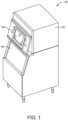
- FIG. 1 illustrates a conventional commercial ice maker 10 having an ice making assembly disposed inside of a cabinet 12 that may be mounted on top of an ice storage bin 14.
- the ice storage bin 14 may include a door 16 that can be opened to provide access to the ice stored therein.
- the ice maker 10 may have other convention components not described herein without departing from the scope of the invention.
- FIG. 2 illustrates certain principal components of one embodiment of an ice making assembly 20 having a water circuit 22 and two refrigeration circuits, 24 and 26.
- the refrigeration circuits may be formed with identical components and, therefore, such components will be described using like reference numbers.
- the water circuit 22 may include a water reservoir 26, water pump 28 circulating water to a water distribution manifold or tube 30 for distribution across an evaporator assembly 32.
- water pump 28 circulating water to a water distribution manifold or tube 30 for distribution across an evaporator assembly 32.
- the water reservoir 26 may be positioned below the evaporator assembly 32 to catch the water coming off of assembly 32 such that the water may be recirculated by water pump 28.
- the water circuit 22 may further include water supply line 36, water filter 38 and water inlet valve 40 disposed thereon for filling the water reservoir 26 with water from a water supply, wherein some or all of the supplied water may be frozen into ice.
- the water reservoir 26 may include some form of a water level sensor, such as a float or conductivity meter, as is known in the art.
- the water circuit 22 may further include a water purge line 42 and purge valve 44 disposed thereon. Water and/or any contaminants remaining in reservoir 26 after ice has been formed may be purged via purge valve 44 through the purge line 42.
- Each of the refrigeration circuits 24 and 26 may include a compressor 50, condenser 52 for condensing compressed refrigerant vapor discharged from the compressor 50, a condensing fan 54 positioned to blow a gaseous cooling medium across condenser 52, a drier 56, a heat exchanger 58, thermal expansion device 60 for lowering the temperature and pressure of the refrigerant, a strainer 62, and hot gas bypass valve 64. As described more fully elsewhere herein, a form of refrigerant cycles through these components.
- Thermal expansion device 60 may include, but is not limited to, a capillary tube, a thermostatic expansion valve or an electronic expansion valve.
- water circuit 22 may also include a temperature sensing bulb placed at the outlet of the evaporator assembly 32 to control thermal expansion device 60.
- thermal expansion device 60 is an electronic expansion valve
- water circuit 22 may also include a pressure sensor (not shown) placed at the outlet of the evaporator assembly 32 to control thermal expansion device 60 as is known in the art.
- the refrigeration circuits 24 and 26, as well as the water circuit 22 may be controlled by controller 70 for the startup, freezing, and harvesting cycles through a series of relays.
- the controller 70 may include a processor along with processor-readable medium storing code representing instructions to cause processor to perform a process.
- the processor may be, for example, a commercially available microprocessor, an application-specific integrated circuit (ASIC) or a combination of ASICs, which are designed to achieve one or more specific functions, or enable one or more specific devices or applications.
- controller 70 may be an analog or digital circuit, or a combination of multiple circuits.
- Controller 70 may also include one or more memory components (not shown) for storing data in a form retrievable by controller 70. Controller 70 can store data in or retrieve data from the one or more memory components.
- Controller 70 may also include a timer for measuring elapsed time. The timer may be implemented via hardware and/or software on or in controller 70 and/or in the processor in any manner known in the art without departing from the scope of the invention.
- each of the refrigeration circuits is charged with a hydrocarbon refrigerant, such as propane R290, to a certain charging limit, between 100 and 300 grams, or preferably up to about 150 grams.
- a hydrocarbon refrigerant such as propane R290
- each compressor 50 receives low-pressure, substantially gaseous refrigerant from evaporator assembly 32 through an associated line (line 76 for the first refrigeration circuit 24 and line 78 for the second refrigeration circuit 26).
- the compressor 50 pressurizes the refrigerant, and discharges high-pressure, substantially gaseous refrigerant to condenser 52.
- the difference in pressure between suction side of the compressor 50 and the discharge side of the compressor 50 may be determined using two pressure sensors located on the suction and discharge lines, Ps 82 and Pd 84.
- Ps 82 and Pd 84 In condenser 52, heat is removed from the refrigerant, causing the substantially gaseous refrigerant to condense into a substantially liquid refrigerant.
- the high-pressure, substantially liquid refrigerant is routed through the drier 56 to remove moisture and, if the drier 56 includes a form of filter such as a mesh screen, to remove certain particulates in the liquid refrigerant.
- the refrigerant then passes through a heat exchanger 58, which uses the warm liquid refrigerant leaving the condenser 52 to heat the cold refrigerant vapor leaving the evaporator assembly 32, and into the thermal expansion device 60, which reduces the pressure of the substantially liquid refrigerant for introduction into evaporator assembly 32 through tee 68 via lines 72 and 74.
- the refrigerant absorbs heat from the tubes contained within evaporator assembly 32 and vaporizes as the refrigerant passes through the tubes, thus cooling evaporator 32.
- Low-pressure, substantially gaseous refrigerant is discharged from the outlet of evaporator assembly 32 through a suction line (line 76 for the first refrigeration circuit 24 and line 78 for the second refrigeration circuit 26), and is reintroduced into the inlet of each compressor 50.
- Figures 3 and 4 illustrate the first tubing 90 and second tubing 92 of evaporator assembly 32.
- the first tubing 90 has an inlet 94 connected to line suction 72 and an outlet 96 connected to suction line 76.
- the second tubing 92 has an inlet 98 connected to line suction 74 and an outlet 100 connected to suction line 78.
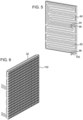
- Figure 5 illustrates the first tubing 90 and the second tubing 92 thermally coupled to rear side of freeze plate 102 of the evaporator assembly 32.
- Figure 6 shows the front view of the freeze plate 102 of evaporator assembly 32.
- the first tubing 90 and the second tubing 92 are preferably serpentine-shaped such that they may be interleaved with one another as illustrated in Figure 5 .
- Such an arrangement assists in ensuring a consistent temperature across the freeze plate 102, and thus, maximizing ice production by allowing for an even bridge thickness during ice making, while simultaneously minimizing the percentage of ice melt required to release the full batch during harvest.
- the refrigeration circuits 24 and 26 may each be charged at a level acceptable to meet the limitations of the IEC, while still providing a sufficiently high cooling capability to meet the needs of the commercial ice maker industry.
- the first and second tubing 90 and 92 depicted in Figure 5 have a circular cross section and are arranged in a serpentine-like shape, such that the combination of the two tubings are distributed over the freeze plate to provide substantially uniform cooling over the freeze plate.
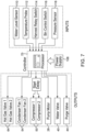
- Figure 7 illustrates the principal inputs and outputs to the controller 70 that may be included in one or more embodiments of the ice maker assembly 20.
- the inputs may include some combination of a water level sensor 110 measuring the level of the water the reservoir 26, a temperature probe 112 measuring the temperature near the evaporator assembly 32, a harvest relay switch 114 that is activated based on a certain amount of ice formed on the freeze plate, a bin control switch 116 that detects the fullness of the ice storage bin 14, and a pressure sensor 118 that may be used to detect the water pressure proximate the bottom of the reservoir 26, which can be correlated to the water level in reservoir 26.
- the controller 70 issues signals to control the hot gas valve 64, condenser fan 54, and compressor 50 of each refrigeration circuit 24 and 26, and the circulation pump 28, water valve 40 and purge valve 44 of the water circuit 22.
- the controller 70 receives operating power through a conventional power supply 108.
- each compressor 50 receives low-pressure, substantially gaseous refrigerant from evaporator assembly 32 through suction lines 76 and 78, pressurizes the refrigerant, and discharges high-pressure, substantially gaseous refrigerant to condenser 52.
- condenser 52 heat is removed from the refrigerant, causing the substantially gaseous refrigerant to condense into a substantially liquid refrigerant.
- the high-pressure, substantially liquid refrigerant is routed through the drier 56, across the heat exchanger 58 and to the thermal expansion device 60, which reduces the pressure of the substantially liquid refrigerant for introduction into the first and second tubing 90 and 92 of the evaporator assembly 32 via lines 72 and 74 respectfully.
- the refrigerant absorbs heat from the tubes contained within evaporator assembly 32 and vaporizes as the refrigerant passes through the tubes thus cooling the freeze plate.
- Low-pressure, substantially gaseous refrigerant is discharged from the outlet of evaporator assembly 32 through line 74 and 78, passes across the heat exchanger 58, and is reintroduced into the inlet of compressor 50.
- water inlet valve 40 may be turned on to supply water to reservoir 26. After the desired level of water is supplied to reservoir 26, the water inlet valve 40 may be closed.
- Water pump 28 circulates the water from reservoir 26 to freeze plate 102 via distributor manifold or tube 30.
- Compressor 50 causes refrigerant to flow through the refrigeration system.
- the water that is supplied by water pump 28 then, during the sensible cooling cycle, begins to cool as it contacts freeze plate 30, returns to water reservoir 26 below freeze plate 102 and is recirculated by water pump 28 to freeze plate 102. Once the cooling cycle enters the latent cooling cycle, water flowing across freeze plate 102 starts forming ice cubes.
- the controller 70 may monitor either the amount of ice forming as measured by an ice thickness sensor, the decrease in the water in the reservoir 26 as measured by the water level sensor, or some other refrigeration system parameter to determine the desirable batch weight.
- the state of the freeze cycle may be calibrated to the water level in reservoir 26. Controller 70 can thus monitor the water level in reservoir 26 and can control the various components accordingly.
- the controller 70 opens the purge valve 42 to remove the remaining water and impurities from the reservoir 26.
- the water circuit 22 and the refrigeration circuits 24 and 26 are disabled.
- hot gas valve 64 is opened allowing warm, high-pressure gas from compressor 50 to flow through a hot gas bypass line, through strainer 62 capable of removing particulates from the gas, check valve 80, and tee 68 to enter the tubing of the evaporator assembly 32, thereby harvesting the ice by warming freeze plate 102 to melt the formed ice to a degree such that the ice may be released from freeze plate 102 and fall into ice storage bin 14 where the ice can be temporarily stored and later retrieved.
- the hot gas valve 64 is then closed and the cooling cycle can repeat.
- Several methods may be used to terminate the harvest cycle, each with the goal of improving the yield of ice produced and preventing the build-up of unharvested ice from cycle to cycle.
- One method is to monitor the evaporator outlet temperature, wait for it to reach some minimum value, and then incorporate time delay for safety. This indirect method of terminating harvest can prove unreliable over the life of the ice maker due to evaporator scaling from heavy sediment and minerals in the potable water supply.
- a more efficient method is to use a mechanical relay to trigger the end of a harvest, thereby eliminating wasted time. In one such case, the relay is attached to a horizontal flap beneath the evaporator assembly 32 and placed directly in the path of the sliding ice.
- the relay is triggered and sends a signal to the controller 70 to immediately terminate the harvest.
- the water supply valve 40 opens for a short time to refill the reservoir 26 with fresh water.
- the ice maker continues alternating freeze and harvest cycles until either the ice bin sensor is satisfied, the ice maker satisfies some programmed, preset schedule stored in the controller's memory, or the unit is shutdown either manually or automatically from some safety device or feature embedded within the controller.
- the refrigeration circuits 24 and 26 may include single speed compressors 50 along with two thermostatic expansion valves 60 to maintain a superheat setting at the outlet of each individual circuit.
- known methods for maintaining a balanced system by ensuring the proper charge of R-290 (or other hydrocarbon refrigerant) for each individual circuit may be used to by ensuring a consistent installation of the thermostatic element.
- the refrigeration circuits 24 and 26 may include two variable speed compressors 50 along with two electronic expansion valves 60 for maintaining a superheat setting at the outlet of each individual circuit.
- the refrigeration circuits may include sensing devices, such as Piezo-resistive Micro-Electro-Mechanical Systems (MEMS) technology, to determine the operating characteristics of each circuit and apply a frequency generating function to alter the speed of the compressors in an effort to balance the suction temperatures of the cooling loop, thereby, maintaining an even, more stable differential across the freeze plate.
- MEMS Piezo-resistive Micro-Electro-Mechanical Systems
- the ice making assembly 20 may further include means for operation in the event of a failure of one of the two refrigeration circuits. With only one system operational, it is presumed that the ice making capacity would reduce in half, as would be the case for a traditional, dual ice making system. However, the cycle time may be extended in the event of a failure, thus providing a "fail-safe" by allowing ice making to continue until the system failure was addressed. The evaporator would continue to operate and scale proportionately to the actual run time of the system, and no additional or alternate cleaning schedule would need to be employed. The controller could further notify the end user through means of an external display that the ice maker was operating in said "fail-safe" mode.
- the ice making assembly may also include the ability to operate in a reduced capacity mode, wherein only one of the refrigeration circuits would be operational, and therefore, half of the ice capacity could be used during periods of low ice demands or in an effort to save energy consumption.
- the refrigeration circuits may use spiral tubed, water-cooled condensers in place of the traditional fin and tube air cooled condensers.
- Other alternatives include the use of brazed plate heat exchangers as the condensing apparatus.
- the condensers could be employed either in tandem on separate circuits, or employed as a single heat exchanger with dual ports to further minimize the number of required components for the ice making assembly.
- an ice making machine that includes a refrigeration system designed for hydrocarbon refrigerants, and particularly propane (R-290), that includes dual independent refrigeration systems and a unique evaporator assembly having a single freeze plate attached to two cooling circuits.
- the evaporator assembly uses two serpentine-shaped tubing sections designed in an advantageous pattern that promotes efficiency by ensuring the even bridging of ice during freezing and minimizing unwanted melting during harvest by providing an even distribution of the heat load.
Landscapes
- Engineering & Computer Science (AREA)
- Physics & Mathematics (AREA)
- Mechanical Engineering (AREA)
- Thermal Sciences (AREA)
- General Engineering & Computer Science (AREA)
- Production, Working, Storing, Or Distribution Of Ice (AREA)
- Heat-Exchange Devices With Radiators And Conduit Assemblies (AREA)
Claims (11)
- Eiserzeugungsanlage (20) zur Bildung von Eis mittels eines Kältemittels, das zwischen einem flüssigen und einem gasförmigen Zustand wechseln kann, wobei der Eiserzeuger Folgendes umfasst:einen ersten Kältekreislauf (24), der einen Kompressor (50), einen Kondensator (52), ein Heißgasventil (64), eine Expansionsvorrichtung (60) und Verbindungsleitungen (76) dafür umfasst, wobei das Kältemittel etwa 100 bis 300 Gramm Kohlenwasserstoff-Kältemittel ist;einen zweiten Kältekreislauf (26), der einen Kompressor, einen Kondensator, ein Heißgasventil, eine Expansionsvorrichtung und Verbindungsleitungen dafür umfasst, wobei das Kältemittel ebenfalls etwa 100 bis 300 Gramm Kohlenwasserstoff-Kältemittel ist;eine einzelne, gemeinsam genutzte Verdampferanordnung (32), die Folgendes umfasst:eine erste Kältemittelleitung in Fluidverbindung mit dem ersten Kältekreislauf, so dass das Kältemittel durch die erste Kältemittelleitung und den ersten Kältekreislauf zirkulieren kann;eine zweite Kältemittelleitung in Fluidverbindung mit dem zweiten Kältekreislauf, so dass das Kältemittel durch die zweite Kältemittelleitung und den zweiten Kältekreislauf zirkulieren kann; undeine Gefrierplatte (34), die thermisch mit der ersten und zweiten Kältemittelleitung verbunden ist; undein Wassersystem zum Zuführen von Wasser zu der Gefrierplatte;wobei die erste und die zweite Kältemittelleitung jeweils serpentinenförmig ausgebildet sind und die beiden serpentinenförmigen Leitungsabschnitte beim Ernten für eine gleichmäßige Verteilung der Wärmebelastung sorgen.
- Eiserzeugungsanlage nach Anspruch 1, wobei das Kohlenwasserstoff-Kältemittel Propan (R-290) ist.
- Eiserzeugungsanlage nach Anspruch 1, wobei die erste und die zweite Kältemittelleitung als Teil der Verdampferanordnung ineinander verschachtelt sind.
- Eiserzeugungsanlage nach Anspruch 1, wobei die erste und die zweite Kältemittelleitung über die Gefrierplatte verteilt sind, um für eine im Wesentlichen gleichmäßige Kühlung über die Gefrierplatte zu sorgen.
- Eiserzeugungsanlage nach Anspruch 1, die ferner eine Steuerung (70) zum Steuern des Betriebs jedes der Kältekreisläufe und des Wasserkreislaufs umfasst.
- Eiserzeugungsanlage nach Anspruch 5, wobei die Steuerung den Betrieb jedes der Kältekreisläufe und des Wasserkreislaufs für einen Einschaltzyklus, einen Gefrierzyklus und einen Erntezyklus über eine Reihe von Relais steuert.
- Eiserzeugungsanlage nach Anspruch 5, wobei die Steuerung den Betrieb eines der Kältekreisläufe unterbricht, so dass die Eiserzeugungsanlage in einem Modus mit reduzierter Kapazität arbeitet.
- Eiserzeugungsanlage nach Anspruch 1, wobei das Kältemittel auf etwa 150 Gramm aufgefüllt ist.
- Eiserzeugungsanlage nach Anspruch 1, wobei die Kompressoren des ersten und zweiten Kältekreislaufs Kompressoren mit einer einzigen Drehzahl sind.
- Eiserzeugungsanlage nach Anspruch 1, wobei die Kompressoren des ersten und zweiten Kältekreislaufs Kompressoren mit variabler Drehzahl sind.
- Eiserzeugungsanlage nach Anspruch 1, wobei das Wassersystem Folgendes umfasst:eine Wasserpumpe (28);einen Wasserverteiler oberhalb der Gefrierplatte;ein Entleerungsventil (44);ein Wassereinlassventil (40); undeinen Wasserbehälter (26), der sich unterhalb der Gefrierplatte befindet und zum Aufnehmen von Wasser ausgelegt ist, wobei die Wasserpumpe mit dem Behälter und dem Wasserverteiler über eine Wasserleitung in Fluidverbindung steht, um Wasser über die Gefrierplatte zu leiten.
Applications Claiming Priority (2)
| Application Number | Priority Date | Filing Date | Title |
|---|---|---|---|
| US201562270391P | 2015-12-21 | 2015-12-21 | |
| PCT/US2016/067996 WO2017112758A1 (en) | 2015-12-21 | 2016-12-21 | Ice machine with a dual-circuit evaporator for hydrocarbon refrigerant |
Publications (4)
| Publication Number | Publication Date |
|---|---|
| EP3394529A1 EP3394529A1 (de) | 2018-10-31 |
| EP3394529A4 EP3394529A4 (de) | 2019-07-24 |
| EP3394529C0 EP3394529C0 (de) | 2024-09-11 |
| EP3394529B1 true EP3394529B1 (de) | 2024-09-11 |
Family
ID=59064347
Family Applications (1)
| Application Number | Title | Priority Date | Filing Date |
|---|---|---|---|
| EP16880020.9A Active EP3394529B1 (de) | 2015-12-21 | 2016-12-21 | Eismaschine mit einem zweikreisverdampfer für kohlenwasserstoffkältemittel |
Country Status (10)
| Country | Link |
|---|---|
| US (4) | US10502472B2 (de) |
| EP (1) | EP3394529B1 (de) |
| JP (2) | JP7165054B2 (de) |
| KR (1) | KR102622596B1 (de) |
| CN (1) | CN108474605A (de) |
| AU (2) | AU2016378569B2 (de) |
| ES (1) | ES2991242T3 (de) |
| HK (1) | HK1259383A1 (de) |
| MX (2) | MX378951B (de) |
| WO (1) | WO2017112758A1 (de) |
Families Citing this family (36)
| Publication number | Priority date | Publication date | Assignee | Title |
|---|---|---|---|---|
| US10107538B2 (en) | 2012-09-10 | 2018-10-23 | Hoshizaki America, Inc. | Ice cube evaporator plate assembly |
| US10345017B2 (en) * | 2016-05-26 | 2019-07-09 | Hill Phoenix, Inc. | Multi-circuit cooling element for a refrigeration system |
| EP3507871B1 (de) * | 2016-08-31 | 2023-06-07 | NLIGHT, Inc. | Laserkühlsystem |
| GB2562299B (en) * | 2017-05-12 | 2019-10-23 | Airsource Ventilation Ltd | Remote heat transfer device |
| US10288202B2 (en) * | 2017-08-11 | 2019-05-14 | Cheng Yu Faucet Hardware Co., Ltd. | Installation between valve connector and pipe of ice maker |
| EP3766149B1 (de) | 2018-03-12 | 2022-05-11 | Nlight, Inc. | Faserlaser mit variabel gewickelter optischer faser |
| US11255588B2 (en) | 2018-08-03 | 2022-02-22 | Hoshizaki America, Inc. | Ultrasonic bin control in an ice machine |
| US10935263B2 (en) * | 2018-11-09 | 2021-03-02 | Johnson Controls Technology Company | Multi-circuit HVAC system |
| CN109682126B (zh) * | 2019-01-28 | 2024-08-09 | 天津商业大学 | 一种可降低制冷剂充注量的制冷系统 |
| US11255593B2 (en) * | 2019-06-19 | 2022-02-22 | Haier Us Appliance Solutions, Inc. | Ice making assembly including a sealed system for regulating the temperature of the ice mold |
| US12352472B2 (en) * | 2019-07-02 | 2025-07-08 | Heatcraft Refrigeration Products Llc | Cooling system |
| US11542147B2 (en) * | 2019-09-30 | 2023-01-03 | Marmon Foodservice Technologies, Inc. | Beverage dispensers with heat exchangers |
| EP4041842A1 (de) * | 2019-10-07 | 2022-08-17 | Arctiko A/S | Kältemittel mit methan sowie kälteanlage und schrank mit einem solchen kältemittel |
| WO2021106793A1 (ja) * | 2019-11-25 | 2021-06-03 | ダイキン工業株式会社 | 冷媒サイクルシステム |
| CN111023361A (zh) * | 2019-12-16 | 2020-04-17 | 江苏上龙供水设备有限公司 | 一种制冰制冷双工况热泵机组 |
| US11255589B2 (en) * | 2020-01-18 | 2022-02-22 | True Manufacturing Co., Inc. | Ice maker |
| US11802727B2 (en) | 2020-01-18 | 2023-10-31 | True Manufacturing Co., Inc. | Ice maker |
| US11391500B2 (en) | 2020-01-18 | 2022-07-19 | True Manufacturing Co., Inc. | Ice maker |
| US11602059B2 (en) | 2020-01-18 | 2023-03-07 | True Manufacturing Co., Inc. | Refrigeration appliance with detachable electronics module |
| US11913699B2 (en) | 2020-01-18 | 2024-02-27 | True Manufacturing Co., Inc. | Ice maker |
| US11656017B2 (en) * | 2020-01-18 | 2023-05-23 | True Manufacturing Co., Inc. | Ice maker |
| US11578905B2 (en) | 2020-01-18 | 2023-02-14 | True Manufacturing Co., Inc. | Ice maker, ice dispensing assembly, and method of deploying ice maker |
| CN110986443B (zh) * | 2020-01-19 | 2024-03-08 | 重庆大学 | 联合制冰机的热源塔热泵系统 |
| US11519652B2 (en) | 2020-03-18 | 2022-12-06 | True Manufacturing Co., Inc. | Ice maker |
| CN111780444B (zh) * | 2020-06-03 | 2021-12-31 | 同济大学 | 一种蒸汽压缩复叠热泵循环和单级热泵循环联合系统 |
| USD1028092S1 (en) * | 2020-06-09 | 2024-05-21 | Stephen Wiliam Clarke | Dispensing device |
| US12135149B2 (en) * | 2020-10-23 | 2024-11-05 | Illuminated Extractors, Ltd. | Heating and refrigeration system |
| US11674731B2 (en) | 2021-01-13 | 2023-06-13 | True Manufacturing Co., Inc. | Ice maker |
| US20220268504A1 (en) * | 2021-02-23 | 2022-08-25 | True Manufacturing Co., Ltd. | Ice maker |
| US12152818B2 (en) * | 2021-02-24 | 2024-11-26 | C. Nelson Mfg. | Method and system for operating a refrigeration system |
| US11566831B2 (en) * | 2021-06-29 | 2023-01-31 | Thomas Mullenaux | Water-dispensing system for use with an icemaker |
| US11686519B2 (en) | 2021-07-19 | 2023-06-27 | True Manufacturing Co., Inc. | Ice maker with pulsed fill routine |
| CN114518003A (zh) * | 2022-01-27 | 2022-05-20 | 宜珈科技(江门市)有限责任公司 | 一种分离式速冻设备 |
| USD1104009S1 (en) | 2023-03-29 | 2025-12-02 | True Manufacturing Co., Inc. | Display screen including icons |
| USD1105164S1 (en) | 2023-03-29 | 2025-12-09 | True Manufacturing Co., Inc. | Display screen including icons |
| USD1082838S1 (en) * | 2023-03-31 | 2025-07-08 | True Manufacturing Co., Inc. | Display screen or portion thereof with graphical user interface |
Citations (1)
| Publication number | Priority date | Publication date | Assignee | Title |
|---|---|---|---|---|
| US20130180268A1 (en) * | 2012-01-13 | 2013-07-18 | Manitowoc Foodservice Companies, Llc | Low refrigerant volume condenser for hydrocarbon refrigerant and ice making machine using same |
Family Cites Families (45)
| Publication number | Priority date | Publication date | Assignee | Title |
|---|---|---|---|---|
| US4187690A (en) * | 1978-08-16 | 1980-02-12 | Gulf & Western Manufacturing Company | Ice-maker heat pump |
| US4332137A (en) * | 1979-10-22 | 1982-06-01 | Carrier Corporation | Heat exchange apparatus and method having two refrigeration circuits |
| US4344298A (en) * | 1980-09-24 | 1982-08-17 | Biemiller John E | Ice cube forming tray for ice making machine |
| US4366679A (en) | 1981-04-08 | 1983-01-04 | Mile High Equipment Company | Evaporator plate for ice cube making apparatus |
| JPS6016708Y2 (ja) | 1981-06-16 | 1985-05-23 | サンウエーブ工業株式会社 | 排水トラツプ |
| JPS58110777A (ja) | 1981-12-25 | 1983-07-01 | 株式会社大井製作所 | 自動ドア開閉装置における連結部構造 |
| JPS58110777U (ja) * | 1982-01-20 | 1983-07-28 | 星崎電機株式会社 | 製氷機における製氷室 |
| US4474023A (en) * | 1983-02-02 | 1984-10-02 | Mullins Jr James N | Ice making |
| JPS62154381U (de) * | 1986-03-20 | 1987-09-30 | ||
| US4774814A (en) * | 1986-09-05 | 1988-10-04 | Mile High Equipment Company | Ice making machine |
| US4903505A (en) * | 1989-01-30 | 1990-02-27 | Hoshizaki Electric Co., Ltd. | Automatic ice manufacturing apparatus |
| US4884413A (en) * | 1989-03-13 | 1989-12-05 | Specialty Equipment Companies, Inc. | Ice machine |
| JPH04121201A (ja) | 1990-09-11 | 1992-04-22 | Io Ind Kk | ホイールキャップ |
| JP2547607Y2 (ja) * | 1991-04-15 | 1997-09-10 | ホシザキ電機株式会社 | 製氷袋詰め機 |
| US5289691A (en) * | 1992-12-11 | 1994-03-01 | The Manitowoc Company, Inc. | Self-cleaning self-sterilizing ice making machine |
| US5711159A (en) * | 1994-09-07 | 1998-01-27 | General Electric Company | Energy-efficient refrigerator control system |
| US5653114A (en) * | 1995-09-01 | 1997-08-05 | Nartron Corporation | Method and system for electronically controlling the location of the formation of ice within a closed loop water circulating unit |
| US5606869A (en) * | 1996-04-08 | 1997-03-04 | Joo; Sung I. | Cylindrical ice cube maker |
| US5878583A (en) * | 1997-04-01 | 1999-03-09 | Manitowoc Foodservice Group, Inc. | Ice making machine and control method therefore |
| US5954127A (en) | 1997-07-16 | 1999-09-21 | International Business Machines Corporation | Cold plate for dual refrigeration system |
| US6161396A (en) * | 1999-06-09 | 2000-12-19 | Scotsman Group, Inc. | Evaporator plate assembly for use in a machine for producing ice |
| JP2001074344A (ja) | 1999-09-03 | 2001-03-23 | Hitachi Ltd | 伝熱装置 |
| US6681580B2 (en) | 2001-09-12 | 2004-01-27 | Manitowoc Foodservice Companies, Inc. | Ice machine with assisted harvest |
| US6651448B2 (en) * | 2002-02-12 | 2003-11-25 | Harold F. Ross | Ice cream machine including a controlled input to the freezing chamber |
| EP1604158A4 (de) | 2003-03-07 | 2006-05-17 | Scotsman Ice Systems | Eismaschinenverdampferanordnungen mit verbesserter wärmeübertragung und herstellungsverfahren dafür |
| WO2004083971A2 (en) * | 2003-03-13 | 2004-09-30 | Imi Cornelius Inc. | Icemaker control system |
| BR0306232A (pt) * | 2003-11-28 | 2005-07-19 | Multibras Eletrodomesticos Sa | Aperfeiçoamento em sistema de refrigeração de gabinetes |
| US6886349B1 (en) * | 2003-12-22 | 2005-05-03 | Lennox Manufacturing Inc. | Brazed aluminum heat exchanger |
| US7661275B2 (en) * | 2005-10-06 | 2010-02-16 | Mile High Equipment L.L.C. | Ice making method and machine with PETD harvest |
| JP2008209083A (ja) | 2007-02-28 | 2008-09-11 | Toshiba Carrier Corp | 空気調和機 |
| US20090211269A1 (en) * | 2008-02-21 | 2009-08-27 | David Brett Gist | Adaptive beater and scraper speed control for frozen product dispensers |
| JP2010156485A (ja) | 2008-12-26 | 2010-07-15 | Hitachi Appliances Inc | マルチ型空気調和機 |
| JP2011038729A (ja) * | 2009-08-12 | 2011-02-24 | Hoshizaki Electric Co Ltd | 冷凍装置 |
| CN102445036A (zh) * | 2010-09-30 | 2012-05-09 | 浙江青风制冷设备制造有限公司 | 制冰机 |
| US20120060545A1 (en) * | 2010-12-02 | 2012-03-15 | General Electric Company | Condenser assembly for multiple refrigeration systems |
| JP2013044469A (ja) | 2011-08-24 | 2013-03-04 | Panasonic Corp | 冷凍空調装置 |
| US10107538B2 (en) * | 2012-09-10 | 2018-10-23 | Hoshizaki America, Inc. | Ice cube evaporator plate assembly |
| US20140209125A1 (en) | 2013-01-25 | 2014-07-31 | True Manufacturing Company, Inc. | Ice maker with slide out sump |
| US20140260375A1 (en) | 2013-03-15 | 2014-09-18 | Illinois Tool Works Inc. | Modular cooling system for beverage dispenser and related methods |
| JP2015087050A (ja) * | 2013-10-30 | 2015-05-07 | ホシザキ電機株式会社 | 製氷機 |
| US9528726B2 (en) * | 2014-03-14 | 2016-12-27 | Hussmann Corporation | Low charge hydrocarbon refrigeration system |
| ES2754583T3 (es) * | 2014-09-05 | 2020-04-20 | Carrier Corp | Intercambiador de calor extruido de múltiples puertos |
| MX391273B (es) * | 2015-05-11 | 2025-03-21 | True Mfg Co Inc | Máquina de hielo con notificación automática para indicar cuándo se requiere mantenimiento. |
| US20160347598A1 (en) * | 2015-05-26 | 2016-12-01 | Mark Kevin Gannon | Beverage cooler |
| CN104896641B (zh) * | 2015-06-29 | 2017-10-27 | 中机西南能源科技有限公司 | 一种双蒸发器动态冰蓄冷系统 |
-
2016
- 2016-12-21 AU AU2016378569A patent/AU2016378569B2/en not_active Ceased
- 2016-12-21 KR KR1020187020458A patent/KR102622596B1/ko active Active
- 2016-12-21 EP EP16880020.9A patent/EP3394529B1/de active Active
- 2016-12-21 CN CN201680079591.3A patent/CN108474605A/zh active Pending
- 2016-12-21 ES ES16880020T patent/ES2991242T3/es active Active
- 2016-12-21 WO PCT/US2016/067996 patent/WO2017112758A1/en not_active Ceased
- 2016-12-21 MX MX2018007526A patent/MX378951B/es unknown
- 2016-12-21 US US15/386,578 patent/US10502472B2/en active Active
- 2016-12-21 JP JP2018532232A patent/JP7165054B2/ja active Active
- 2016-12-21 HK HK19101751.6A patent/HK1259383A1/zh unknown
-
2018
- 2018-06-19 MX MX2021000261A patent/MX2021000261A/es unknown
-
2019
- 2019-10-02 US US16/590,484 patent/US10677505B2/en active Active
-
2020
- 2020-05-01 US US16/864,346 patent/US11231218B2/en active Active
-
2021
- 2021-01-22 AU AU2021200441A patent/AU2021200441B2/en active Active
- 2021-07-19 JP JP2021119046A patent/JP7025587B2/ja active Active
-
2022
- 2022-01-07 US US17/570,860 patent/US11846459B2/en active Active
Patent Citations (1)
| Publication number | Priority date | Publication date | Assignee | Title |
|---|---|---|---|---|
| US20130180268A1 (en) * | 2012-01-13 | 2013-07-18 | Manitowoc Foodservice Companies, Llc | Low refrigerant volume condenser for hydrocarbon refrigerant and ice making machine using same |
Also Published As
| Publication number | Publication date |
|---|---|
| ES2991242T3 (es) | 2024-12-03 |
| US20200256605A1 (en) | 2020-08-13 |
| EP3394529C0 (de) | 2024-09-11 |
| EP3394529A4 (de) | 2019-07-24 |
| MX378951B (es) | 2025-03-11 |
| KR102622596B1 (ko) | 2024-01-10 |
| AU2016378569A1 (en) | 2018-07-05 |
| KR20180087436A (ko) | 2018-08-01 |
| JP2021167725A (ja) | 2021-10-21 |
| AU2021200441A1 (en) | 2021-02-25 |
| US20220349641A1 (en) | 2022-11-03 |
| MX2018007526A (es) | 2018-09-07 |
| US10502472B2 (en) | 2019-12-10 |
| JP7025587B2 (ja) | 2022-02-24 |
| US20170176077A1 (en) | 2017-06-22 |
| JP2019500569A (ja) | 2019-01-10 |
| CN108474605A (zh) | 2018-08-31 |
| WO2017112758A1 (en) | 2017-06-29 |
| US20200033043A1 (en) | 2020-01-30 |
| HK1259383A1 (zh) | 2019-11-29 |
| EP3394529A1 (de) | 2018-10-31 |
| AU2016378569B2 (en) | 2020-12-10 |
| AU2021200441B2 (en) | 2022-09-29 |
| US11231218B2 (en) | 2022-01-25 |
| MX2021000261A (es) | 2021-04-12 |
| US11846459B2 (en) | 2023-12-19 |
| JP7165054B2 (ja) | 2022-11-02 |
| US10677505B2 (en) | 2020-06-09 |
Similar Documents
| Publication | Publication Date | Title |
|---|---|---|
| AU2021200441B2 (en) | Ice machine with a dual-circuit evaporator for hydrocarbon refrigerant | |
| US20240142152A1 (en) | Ice maker with push notification to indicate when maintenance is required | |
| US11543161B2 (en) | Ice maker with reversing condenser fan motor to maintain clean condenser | |
| US10557656B2 (en) | Ice discharging apparatus for vertical spray-type ice machines | |
| US10094607B2 (en) | Ice maker with slush-avoiding sump | |
| JP5366764B2 (ja) | 冷却装置及び冷凍サイクル装置 | |
| JP2009121768A (ja) | 自動製氷機およびその制御方法 | |
| US20240247852A1 (en) | Refrigerator and ice-making assembly and methods for reliably forming clear ice | |
| US12209786B2 (en) | Refrigerator and ice-making assembly having a removable water basin | |
| US12326287B2 (en) | Refrigerator and ice-making assembly for making and holding clear ice billets |
Legal Events
| Date | Code | Title | Description |
|---|---|---|---|
| STAA | Information on the status of an ep patent application or granted ep patent |
Free format text: STATUS: THE INTERNATIONAL PUBLICATION HAS BEEN MADE |
|
| PUAI | Public reference made under article 153(3) epc to a published international application that has entered the european phase |
Free format text: ORIGINAL CODE: 0009012 |
|
| STAA | Information on the status of an ep patent application or granted ep patent |
Free format text: STATUS: REQUEST FOR EXAMINATION WAS MADE |
|
| 17P | Request for examination filed |
Effective date: 20180618 |
|
| AK | Designated contracting states |
Kind code of ref document: A1 Designated state(s): AL AT BE BG CH CY CZ DE DK EE ES FI FR GB GR HR HU IE IS IT LI LT LU LV MC MK MT NL NO PL PT RO RS SE SI SK SM TR |
|
| AX | Request for extension of the european patent |
Extension state: BA ME |
|
| DAV | Request for validation of the european patent (deleted) | ||
| DAX | Request for extension of the european patent (deleted) | ||
| A4 | Supplementary search report drawn up and despatched |
Effective date: 20190624 |
|
| RIC1 | Information provided on ipc code assigned before grant |
Ipc: F25C 1/22 20180101ALI20190617BHEP Ipc: F25B 7/00 20060101ALI20190617BHEP Ipc: F25B 41/00 20060101ALI20190617BHEP Ipc: F25B 9/00 20060101ALI20190617BHEP Ipc: F25C 1/04 20180101AFI20190617BHEP |
|
| STAA | Information on the status of an ep patent application or granted ep patent |
Free format text: STATUS: EXAMINATION IS IN PROGRESS |
|
| 17Q | First examination report despatched |
Effective date: 20211013 |
|
| GRAP | Despatch of communication of intention to grant a patent |
Free format text: ORIGINAL CODE: EPIDOSNIGR1 |
|
| STAA | Information on the status of an ep patent application or granted ep patent |
Free format text: STATUS: GRANT OF PATENT IS INTENDED |
|
| INTG | Intention to grant announced |
Effective date: 20231031 |
|
| GRAJ | Information related to disapproval of communication of intention to grant by the applicant or resumption of examination proceedings by the epo deleted |
Free format text: ORIGINAL CODE: EPIDOSDIGR1 |
|
| STAA | Information on the status of an ep patent application or granted ep patent |
Free format text: STATUS: EXAMINATION IS IN PROGRESS |
|
| GRAP | Despatch of communication of intention to grant a patent |
Free format text: ORIGINAL CODE: EPIDOSNIGR1 |
|
| STAA | Information on the status of an ep patent application or granted ep patent |
Free format text: STATUS: GRANT OF PATENT IS INTENDED |
|
| INTC | Intention to grant announced (deleted) | ||
| INTG | Intention to grant announced |
Effective date: 20240405 |
|
| GRAS | Grant fee paid |
Free format text: ORIGINAL CODE: EPIDOSNIGR3 |
|
| GRAA | (expected) grant |
Free format text: ORIGINAL CODE: 0009210 |
|
| STAA | Information on the status of an ep patent application or granted ep patent |
Free format text: STATUS: THE PATENT HAS BEEN GRANTED |
|
| AK | Designated contracting states |
Kind code of ref document: B1 Designated state(s): AL AT BE BG CH CY CZ DE DK EE ES FI FR GB GR HR HU IE IS IT LI LT LU LV MC MK MT NL NO PL PT RO RS SE SI SK SM TR |
|
| REG | Reference to a national code |
Ref country code: GB Ref legal event code: FG4D |
|
| REG | Reference to a national code |
Ref country code: CH Ref legal event code: EP |
|
| REG | Reference to a national code |
Ref country code: DE Ref legal event code: R096 Ref document number: 602016089395 Country of ref document: DE |
|
| REG | Reference to a national code |
Ref country code: IE Ref legal event code: FG4D |
|
| U01 | Request for unitary effect filed |
Effective date: 20240926 |
|
| U07 | Unitary effect registered |
Designated state(s): AT BE BG DE DK EE FI FR IT LT LU LV MT NL PT RO SE SI Effective date: 20241023 |
|
| REG | Reference to a national code |
Ref country code: ES Ref legal event code: FG2A Ref document number: 2991242 Country of ref document: ES Kind code of ref document: T3 Effective date: 20241203 |
|
| PG25 | Lapsed in a contracting state [announced via postgrant information from national office to epo] |
Ref country code: NO Free format text: LAPSE BECAUSE OF FAILURE TO SUBMIT A TRANSLATION OF THE DESCRIPTION OR TO PAY THE FEE WITHIN THE PRESCRIBED TIME-LIMIT Effective date: 20241211 |
|
| PG25 | Lapsed in a contracting state [announced via postgrant information from national office to epo] |
Ref country code: GR Free format text: LAPSE BECAUSE OF FAILURE TO SUBMIT A TRANSLATION OF THE DESCRIPTION OR TO PAY THE FEE WITHIN THE PRESCRIBED TIME-LIMIT Effective date: 20241212 |
|
| PG25 | Lapsed in a contracting state [announced via postgrant information from national office to epo] |
Ref country code: HR Free format text: LAPSE BECAUSE OF FAILURE TO SUBMIT A TRANSLATION OF THE DESCRIPTION OR TO PAY THE FEE WITHIN THE PRESCRIBED TIME-LIMIT Effective date: 20240911 |
|
| PG25 | Lapsed in a contracting state [announced via postgrant information from national office to epo] |
Ref country code: RS Free format text: LAPSE BECAUSE OF FAILURE TO SUBMIT A TRANSLATION OF THE DESCRIPTION OR TO PAY THE FEE WITHIN THE PRESCRIBED TIME-LIMIT Effective date: 20241211 |
|
| PG25 | Lapsed in a contracting state [announced via postgrant information from national office to epo] |
Ref country code: RS Free format text: LAPSE BECAUSE OF FAILURE TO SUBMIT A TRANSLATION OF THE DESCRIPTION OR TO PAY THE FEE WITHIN THE PRESCRIBED TIME-LIMIT Effective date: 20241211 Ref country code: NO Free format text: LAPSE BECAUSE OF FAILURE TO SUBMIT A TRANSLATION OF THE DESCRIPTION OR TO PAY THE FEE WITHIN THE PRESCRIBED TIME-LIMIT Effective date: 20241211 Ref country code: HR Free format text: LAPSE BECAUSE OF FAILURE TO SUBMIT A TRANSLATION OF THE DESCRIPTION OR TO PAY THE FEE WITHIN THE PRESCRIBED TIME-LIMIT Effective date: 20240911 Ref country code: GR Free format text: LAPSE BECAUSE OF FAILURE TO SUBMIT A TRANSLATION OF THE DESCRIPTION OR TO PAY THE FEE WITHIN THE PRESCRIBED TIME-LIMIT Effective date: 20241212 |
|
| U20 | Renewal fee for the european patent with unitary effect paid |
Year of fee payment: 9 Effective date: 20241227 |
|
| U1N | Appointed representative for the unitary patent procedure changed after the registration of the unitary effect |
Representative=s name: POTTER, JULIAN MARK; GB |
|
| PG25 | Lapsed in a contracting state [announced via postgrant information from national office to epo] |
Ref country code: IS Free format text: LAPSE BECAUSE OF FAILURE TO SUBMIT A TRANSLATION OF THE DESCRIPTION OR TO PAY THE FEE WITHIN THE PRESCRIBED TIME-LIMIT Effective date: 20250111 |
|
| PG25 | Lapsed in a contracting state [announced via postgrant information from national office to epo] |
Ref country code: SM Free format text: LAPSE BECAUSE OF FAILURE TO SUBMIT A TRANSLATION OF THE DESCRIPTION OR TO PAY THE FEE WITHIN THE PRESCRIBED TIME-LIMIT Effective date: 20240911 |
|
| PG25 | Lapsed in a contracting state [announced via postgrant information from national office to epo] |
Ref country code: CZ Free format text: LAPSE BECAUSE OF FAILURE TO SUBMIT A TRANSLATION OF THE DESCRIPTION OR TO PAY THE FEE WITHIN THE PRESCRIBED TIME-LIMIT Effective date: 20240911 Ref country code: PL Free format text: LAPSE BECAUSE OF FAILURE TO SUBMIT A TRANSLATION OF THE DESCRIPTION OR TO PAY THE FEE WITHIN THE PRESCRIBED TIME-LIMIT Effective date: 20240911 |
|
| PG25 | Lapsed in a contracting state [announced via postgrant information from national office to epo] |
Ref country code: SK Free format text: LAPSE BECAUSE OF FAILURE TO SUBMIT A TRANSLATION OF THE DESCRIPTION OR TO PAY THE FEE WITHIN THE PRESCRIBED TIME-LIMIT Effective date: 20240911 |
|
| PG25 | Lapsed in a contracting state [announced via postgrant information from national office to epo] |
Ref country code: MC Free format text: LAPSE BECAUSE OF FAILURE TO SUBMIT A TRANSLATION OF THE DESCRIPTION OR TO PAY THE FEE WITHIN THE PRESCRIBED TIME-LIMIT Effective date: 20240911 |
|
| PLBE | No opposition filed within time limit |
Free format text: ORIGINAL CODE: 0009261 |
|
| STAA | Information on the status of an ep patent application or granted ep patent |
Free format text: STATUS: NO OPPOSITION FILED WITHIN TIME LIMIT |
|
| REG | Reference to a national code |
Ref country code: CH Ref legal event code: PL |
|
| 26N | No opposition filed |
Effective date: 20250612 |
|
| PG25 | Lapsed in a contracting state [announced via postgrant information from national office to epo] |
Ref country code: CH Free format text: LAPSE BECAUSE OF NON-PAYMENT OF DUE FEES Effective date: 20241231 |
|
| PG25 | Lapsed in a contracting state [announced via postgrant information from national office to epo] |
Ref country code: IE Free format text: LAPSE BECAUSE OF NON-PAYMENT OF DUE FEES Effective date: 20241221 |
|
| PGFP | Annual fee paid to national office [announced via postgrant information from national office to epo] |
Ref country code: GB Payment date: 20251229 Year of fee payment: 10 |
|
| U20 | Renewal fee for the european patent with unitary effect paid |
Year of fee payment: 10 Effective date: 20251229 |
|
| PGFP | Annual fee paid to national office [announced via postgrant information from national office to epo] |
Ref country code: ES Payment date: 20260102 Year of fee payment: 10 |