EP3394452B1 - Dispositif de raccordement - Google Patents
Dispositif de raccordement Download PDFInfo
- Publication number
- EP3394452B1 EP3394452B1 EP16825345.8A EP16825345A EP3394452B1 EP 3394452 B1 EP3394452 B1 EP 3394452B1 EP 16825345 A EP16825345 A EP 16825345A EP 3394452 B1 EP3394452 B1 EP 3394452B1
- Authority
- EP
- European Patent Office
- Prior art keywords
- connection device
- decoupling
- connection
- tube
- holding elements
- Prior art date
- Legal status (The legal status is an assumption and is not a legal conclusion. Google has not performed a legal analysis and makes no representation as to the accuracy of the status listed.)
- Active
Links
- 239000012530 fluid Substances 0.000 claims description 40
- 238000007789 sealing Methods 0.000 claims description 16
- 230000005540 biological transmission Effects 0.000 claims description 7
- 238000013459 approach Methods 0.000 description 7
- 238000013016 damping Methods 0.000 description 5
- 229920001971 elastomer Polymers 0.000 description 3
- 239000000806 elastomer Substances 0.000 description 3
- 230000006378 damage Effects 0.000 description 2
- 239000002184 metal Substances 0.000 description 2
- 230000008878 coupling Effects 0.000 description 1
- 238000010168 coupling process Methods 0.000 description 1
- 238000005859 coupling reaction Methods 0.000 description 1
- 238000007599 discharging Methods 0.000 description 1
- 238000006073 displacement reaction Methods 0.000 description 1
- 238000005259 measurement Methods 0.000 description 1
- 238000000034 method Methods 0.000 description 1
- 239000007787 solid Substances 0.000 description 1
Images

Classifications
-
- F—MECHANICAL ENGINEERING; LIGHTING; HEATING; WEAPONS; BLASTING
- F16—ENGINEERING ELEMENTS AND UNITS; GENERAL MEASURES FOR PRODUCING AND MAINTAINING EFFECTIVE FUNCTIONING OF MACHINES OR INSTALLATIONS; THERMAL INSULATION IN GENERAL
- F16L—PIPES; JOINTS OR FITTINGS FOR PIPES; SUPPORTS FOR PIPES, CABLES OR PROTECTIVE TUBING; MEANS FOR THERMAL INSULATION IN GENERAL
- F16L55/00—Devices or appurtenances for use in, or in connection with, pipes or pipe systems
- F16L55/04—Devices damping pulsations or vibrations in fluids
-
- F—MECHANICAL ENGINEERING; LIGHTING; HEATING; WEAPONS; BLASTING
- F04—POSITIVE - DISPLACEMENT MACHINES FOR LIQUIDS; PUMPS FOR LIQUIDS OR ELASTIC FLUIDS
- F04D—NON-POSITIVE-DISPLACEMENT PUMPS
- F04D19/00—Axial-flow pumps
- F04D19/02—Multi-stage pumps
- F04D19/04—Multi-stage pumps specially adapted to the production of a high vacuum, e.g. molecular pumps
- F04D19/042—Turbomolecular vacuum pumps
-
- F—MECHANICAL ENGINEERING; LIGHTING; HEATING; WEAPONS; BLASTING
- F04—POSITIVE - DISPLACEMENT MACHINES FOR LIQUIDS; PUMPS FOR LIQUIDS OR ELASTIC FLUIDS
- F04D—NON-POSITIVE-DISPLACEMENT PUMPS
- F04D29/00—Details, component parts, or accessories
- F04D29/60—Mounting; Assembling; Disassembling
- F04D29/601—Mounting; Assembling; Disassembling specially adapted for elastic fluid pumps
-
- F—MECHANICAL ENGINEERING; LIGHTING; HEATING; WEAPONS; BLASTING
- F04—POSITIVE - DISPLACEMENT MACHINES FOR LIQUIDS; PUMPS FOR LIQUIDS OR ELASTIC FLUIDS
- F04D—NON-POSITIVE-DISPLACEMENT PUMPS
- F04D29/00—Details, component parts, or accessories
- F04D29/66—Combating cavitation, whirls, noise, vibration or the like; Balancing
- F04D29/661—Combating cavitation, whirls, noise, vibration or the like; Balancing especially adapted for elastic fluid pumps
- F04D29/668—Combating cavitation, whirls, noise, vibration or the like; Balancing especially adapted for elastic fluid pumps damping or preventing mechanical vibrations
Definitions
- Connecting device for connecting a first pipe end that can be connected to a vacuum pump to a second pipe end that can be connected to a recipient.
- the problem is that vibrations are transmitted from the vacuum pump to the chamber to be evacuated, particularly due to the rotor rotation. These can affect processes or measurements carried out in the chamber being evacuated or a device connected to the chamber being evacuated. For example, electron microscopes are extremely susceptible to vibration.
- a damping element between a pipe end that can be connected to the vacuum pump and a pipe end that can be connected to the chamber to be evacuated.
- This has, for example, a flexible metal bellows to ensure vacuum tightness.
- the metal bellows is surrounded, for example, by an elastic damping element.
- a connecting element is known. This has two pipe pieces, one of the pipe pieces being firmly connected to the pipe end that can be connected to the vacuum pump and the second pipe piece being firmly connected to the pipe end that can be connected to the chamber to be evacuated. Two annular elastomer seals are provided between the two pipe ends. These are surrounded by a clamp-like element, which also has an inward-pointing web arranged between the two sealing elements. When the vacuum pump is not in operation, the two pipe sections are pushed apart by the elastomer rings and are mechanically connected by the clamp surrounding the pipe sections.
- This mechanical connection which would also transmit vibrations, is released by the vacuum generated in such a way that the two elastomer rings are pressed together and the mechanical connection of the two pipe sections is released via the clasp.
- this connection device has the particular disadvantage that the solution to the mechanical connection is not clearly defined. This depends, for example, on the level of vacuum generated. Furthermore, the elastic properties of the sealing rings change, so that they have to be replaced regularly. There is also a risk that the connecting element could leak if there is a lateral load on the pump.
- a connecting device for connecting a first pipe end that can be connected to a vacuum pump to a chamber to be evacuated connectable second pipe end with the features of the preamble of claim 1 is out EP 2 410 184 known.
- the object of the invention is to create a connecting device for connecting a first pipe element that can be connected to a vacuum pump to a second pipe element that can be connected to a chamber to be evacuated, which enables good mechanical decoupling with a high level of safety at the same time.
- the connecting device serves to connect a first pipe end that can be connected to a vacuum pump or a turbomolecular pump to a second pipe end, the second pipe end being connectable to a chamber to be evacuated.
- the first pipe element can also be part of the vacuum pump or the inlet flange of the vacuum pump.
- the second pipe element can also be part of the chamber to be evacuated.
- the connecting element has a tubular element for fluidly connecting the vacuum pump to the chamber to be evacuated.
- the pipe element creates the vacuum connection required for evacuation.
- the tubular element therefore has a connecting element on each side or is connected to a connecting element.
- the two connecting elements serve to connect the pipe element to one of the two pipe ends.
- At least one of the two connecting elements is designed in such a way that it is only suitable for transmitting torque.
- no axial forces i.e. forces running in the longitudinal direction of the tubular element, can be transmitted during operation by the connecting element. This ensures that the transmission of vibrations from the vacuum pump to the chamber to be evacuated or from the first pipe end to the second pipe end is not possible or is at least strongly damped.
- moments can be transmitted by the at least one connecting element. These are moments around the longitudinal axis of the tubular element which occur particularly in the event of a crash but also when the vacuum pump is started up or braked. This ensures appropriate security.
- Both connecting elements are preferably designed in this way. According to the invention, a decoupling element is provided.
- the decoupling element serves to mechanically decouple the at least one connecting element, which is suitable exclusively for transmitting torque, from the corresponding pipe end.
- the decoupling element serves to mechanically decouple both connecting elements, provided that both connecting elements are only suitable for transmitting torque.
- the decoupling element generates an axial force that counteracts the force generated by the vacuum during operation.
- the axial force generated by the decoupling element is greater than the counterforce generated by the vacuum. This creates a mechanical connection between the two pipe ends, so that the moments that occur can be transferred well.
- an axial final coupling occurs during operation due to a balance of forces between the force generated by the decoupling element and the force generated by the vacuum, so that the transmission of vibrations is at least greatly reduced.
- the decoupling element has at least one fluid chamber filled with compressible fluid.
- the fluid is in particular gas and particularly preferably air.
- the decoupling element preferably has at least two holding elements.
- the two holding elements can each be firmly connected to one of the pipe ends. Due to the firm connection between the holding elements and the respective pipe ends, in particular from the pipe end that can be connected to the vacuum pump to the one Holding element and forces and moments are transmitted from the other holding element to the pipe end that can be connected to the chamber to be evacuated. It is also possible for at least one of the two holding elements to be formed in one piece with the corresponding pipe end or for a non-detachable connection to be made.
- the fluid chamber is preferably arranged between the two holding elements. Increasing the pressure in the fluid chamber causes the two holding elements to be pushed apart.
- the decoupling element further has an outer element, in particular completely surrounding the tubular element.
- the outer element is preferably designed in a ring shape.
- the outer element covers the two holding elements in the axial direction, whereby the outer element can also be firmly connected to one of the two holding elements or be formed in one piece. It is preferred that the outer element is not firmly connected to either of the two holding elements.
- the outer element is thus movable in the axial direction in particular to one of the two holding elements and preferably to both holding elements, or a corresponding axial relative movement is made possible.
- a first sealing element is preferably arranged between the outer element and the holding element which is displaceable relative thereto.
- This is in particular an elastic sealing element, in particular a sealing ring surrounding the holding element. Essentially no forces, in particular essentially no vibrations, are transmitted through this.
- a second sealing element is provided, which is arranged between the outer element and the second holding element which is displaceable in particular in the axial direction relative to the outer element.
- the second sealing element is preferably designed corresponding to the first sealing element.
- a sealing element is arranged between the tubular element and the two holding elements. This is preferably designed in accordance with the first sealing element, so that essentially no forces or vibrations are transmitted through it.
- the fluid chamber is delimited by the outer element, the tubular element and the two holding elements.
- the limitation is achieved in particular by an inside of the outer element and an opposite outside of the tubular element.
- the holding elements delimit the fluid chamber in particular by their end faces.
- the fluid chamber is annular and in particular completely surrounds the tubular element. This allows a uniform force to be generated in the axial direction. A change in the force, particularly in the circumferential direction of the preferably annular fluid chamber, is thereby avoided.
- the fluid chamber is connected to a supply channel.
- the supply channel is used to supply fluid, in particular gas.
- a valve is preferably arranged in the feed channel. This makes it possible to easily vary the pressure in the fluid chamber and adapt it to an operating condition. This results in decoupling during operation, so that essentially no vibrations are transmitted from the vacuum pump to the chamber to be evacuated.
- the outer element which is particularly annular, is firmly connected to the tubular element via a web element. This can be done, for example, to simplify assembly using a screw connection. It is also possible to design the tubular element and the outer element in one piece.
- the decoupling element has two fluid chambers. These are in particular one behind the other in the axial direction arranged so that each of the fluid chambers essentially acts on one of the two holding elements. It is particularly preferred that the pressure of the two fluid chambers can be adjusted separately from one another. For this purpose, it is preferably provided that a channel for supplying and discharging compressible fluid such as gas is provided for each fluid chamber and that a valve is preferably arranged in each channel.
- the at least one transmission element suitable for transmitting torque is designed such that axially arranged lugs are provided which protrude into recesses.
- the approaches are provided on the connecting element and the recesses on the holding element.
- the lugs provided on the connecting element point into the recesses provided on the holding element.
- the approaches could also be provided on the connecting element.
- the cross section of the recesses is larger than the cross section of the lugs. This ensures that no moments and therefore no vibrations are transmitted during normal operation.
- Both connecting elements are preferably designed as described above and are advantageously further developed.
- the pressure provided in the at least one fluid chamber initially creates a connection in the axial direction between the two pipe ends between which the connecting element is arranged. This is done in particular by the fact that, in a preferred embodiment, the approaches of the connecting elements rest on the bottom of the corresponding recesses. As soon as a vacuum is generated by the vacuum pump, this creates a axial counterforce that counteracts the axial force generated by the pressure in the at least one fluid chamber. This causes the mechanical connection to be released and thus decoupled.
- a marking in order to be able to easily determine from the outside whether decoupling has occurred at the set vacuum and the set pressure in the at least one fluid chamber.
- a marking can be provided on the outer element and/or at least one of the holding elements.
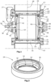
- the connecting device serves to connect a first pipe end 10, which is connected in particular to a vacuum pump, to a second pipe end 12, which is connected in particular to a chamber to be evacuated.
- a pipe element 14 is provided for fluidic connection. This is connected to a connecting ring 16 at its two opposite ends, in particular via fastening screws (not shown).
- the ring 16 has a centering ring 18 with a seal.
- the centering ring 18 is arranged between flanges 20 of the two pipe ends 10, 12 and flanges 22 opposite them.
- the flanges 22 are each part of two holding elements 24.
- the holding elements 24 are each annular and surround the tube element 14.
- the two holding elements 24 are, for example, firmly connected to the first tube end 10 or to the second tube end 12 via clamps 27 and are therefore rigidly connected.
- the tubular element 14 is connected to the two tubular elements 10, 12 via connecting elements 26, the two holding elements 24 also being components of the connecting elements 26.
- the connection is made in such a way that moments can be transmitted through the connection, particularly in the event of a failure of the vacuum pump. These are the moments that occur around a longitudinal axis 28.
- the holding elements 24 ( Fig. 2 ) has a radially inwardly pointing projection 30.
- the approach 30 has recesses 32 into which approaches 34 ( Fig. 1 ) protrude.
- the approaches 34 are screw heads.
- the diameter of the recesses 32 is slightly larger than the diameter of the screw heads 34.
- the connecting device has a decoupling element 36.
- This serves to mechanically decouple the two connecting elements 26 from the two pipe ends 10, 12, so that no axial forces, ie forces that run in the direction of the longitudinal axis 28, can be transmitted or their transmission is strongly damped. In this respect, there is no or very little transmission of vibrations from the vacuum pump to the chamber to be evacuated and the components connected to it.
- the decoupling element 36 has an annular outer element 38.
- the outer element 38 can be displaced in the axial direction, ie in the longitudinal direction 28, relative to the two holding elements 24, which are also annular. Between the outer element 38 and an annular sealing element 40 is arranged in each of the two holding elements 24.
- annular sealing element 42 is optionally provided for sealing against the tubular element 14.
- annular sealing element 42 is optionally provided for sealing against the tubular element 14.
- the outer element 38 of the decoupling element 36 is connected to the tubular element 14 via a web element 44. This is a fixed connection, with the web element 44 being connected to a web-shaped extension 46 of the tubular element 14, for example by screwing. An axial movement of the tubular element 14 always causes an axial movement of the outer element 38.
- two fluid chambers 48, 50 are formed, which are in the in Fig. 1 illustrated embodiment are fluidly connected to one another via a connecting channel 52 provided in the webs 44, 46.
- the fluid chambers 48, 50 are thus delimited by an inside of the outer element 38, end faces of the two holding elements 24 and an outside of the tubular element 14.
- the fluid chambers 48, 50 have a supply channel 54 in which a valve 56 is arranged.
- a fluid, in particular compressed air, can thus be supplied or removed from the two fluid chambers 48, 50 via the valve 56.
- the pressure in the fluid chambers 48, 50 must be adjusted to the vacuum. According to the invention, this is possible in a simple manner by supplying or removing compressed air through the supply channel 54.
- a marking is provided on the outer ring 38 and/or one of the two holding elements 24, so that the position of the outer ring 38 and thus also of the tubular element 14 relative to the holding elements 24 can be read in a simple manner. This allows the required pressure in the fluid chambers 48, 50 to be determined in a simple manner in order to ensure axial decoupling.
- the outer ring 38 is formed in one piece with the tubular element 14.
- the connection is made via a solid web 58.
- the web 58 also has no bores for connecting the two fluid chambers 48, 50. Rather, a feed channel 60 is provided for each fluid chamber 48, 50, in which a valve 62 is arranged. This makes it possible to adjust the pressure in the two fluid chambers 48, 50 independently of one another, so that fine adjustment is possible.
- two markings are provided, with one marking indicating the relative position between the outer element 38 and an in Fig. 1 upper holding element 24 and the second marking the relative position to the in Fig. 3 lower holding element 24 illustrated.
Claims (16)
- Dispositif de liaison permettant de relier une première extrémité de tuyau (10), pouvant être reliée à une pompe à vide, à une seconde extrémité de tuyau (12) pouvant être reliée à une chambre au sein de laquelle le vide doit être créé, comprenantun élément tubulaire (14) permettant de relier fluidiquement la pompe à vide et la chambre au sein de laquelle le vide doit être créé,dans lequel l'élément tubulaire (14) présente de chaque côté un élément de liaison (26) à relier respectivement à une des extrémités de tuyau (10, 12),dans lequel, en cours de fonctionnement, au moins un des deux éléments de liaison (26) est approprié exclusivement pour la transmission de couples etun élément de désaccouplement (36) permettant de désaccoupler axialement de manière mécanique le au moins un élément de liaison (26) approprié exclusivement pour la transmission de couples et l'extrémité de tuyau (10, 12) correspondante,caractérisé en ce quel'élément de désaccouplement (36) présente au moins une chambre à fluide (48, 50) remplie de fluide compressible, en particulier de gaz.
- Dispositif de liaison selon la revendication 1, caractérisé en ce que la force générée par l'élément de désaccouplement (36), en particulier la force axiale générée, peut être ajustée.
- Dispositif de liaison selon la revendication 2, caractérisé en ce que l'ajustement de la force axiale intervient grâce à une modification de pression dans la chambre à fluide (48, 50).
- Dispositif de liaison selon l'une quelconque des revendications 1 à 3, caractérisé en ce que les deux éléments de liaison (26) sont appropriés exclusivement pour la transmission de couples.
- Dispositif de liaison selon l'une quelconque des revendications 1 à 4, caractérisé en ce que l'élément de désaccouplement (36) présente deux éléments de retenue (24) qui peuvent être reliés de manière fixe à respectivement une des extrémités de tube (10, 12), dans lequel la chambre à fluide (48, 50) est de manière préférée agencée entre les deux éléments de retenue (24).
- Dispositif de liaison selon l'une quelconque des revendications 1 à 5, caractérisé en ce que l'élément de désaccouplement (36) présente un élément extérieur (38) entourant en particulier complètement l'élément tubulaire (14).
- Dispositif de liaison selon la revendication 6, caractérisé en ce que l'élément extérieur (38) peut coulisser axialement par rapport à au moins un, en particulier par rapport aux deux, élément(s) de retenue (24).
- Dispositif de liaison selon l'une quelconque des revendications 6 ou 7, caractérisé par un premier élément d'étanchéité (40) agencé entre l'élément extérieur (38) et l'élément de retenue (24) pouvant coulisser par rapport à celui-ci, et de manière préférée par un second élément d'étanchéité (40) agencé entre l'élément extérieur (38) et le second élément de retenue (24) pouvant en particulier également coulisser axialement.
- Dispositif de liaison selon l'une quelconque des revendications 5 à 8, caractérisé en ce que respectivement un élément d'étanchéité (42) est agencé entre l'élément tubulaire (14) et les deux éléments de retenue (24).
- Dispositif de liaison selon l'une quelconque des revendications 6 à 9, caractérisé en ce que la au moins une chambre à fluide (48, 50) est délimitée par l'élément extérieur (38), l'élément tubulaire (14) et les deux éléments de retenue (24).
- Dispositif de liaison selon l'une quelconque des revendications 1 à 10, caractérisé en ce que la au moins une chambre à fluide (48, 50) entoure l'élément tubulaire (14) de manière annulaire.
- Dispositif de liaison selon l'une quelconque des revendications 1 à 11, caractérisé en ce que la au moins une chambre à fluide (48, 50) présente un canal d'alimentation (54, 60) au sein duquel est en particulier agencé un clapet (56, 62).
- Dispositif de liaison selon l'une quelconque des revendications 6 à 12, caractérisé en ce que l'élément extérieur (38) est relié de manière fixe à l'élément tubulaire (14), en particulier par l'intermédiaire d'un élément formant nervure (44, 58), et est en particulier réalisé en une seule pièce.
- Dispositif de liaison selon l'une quelconque des revendications 1 à 13, caractérisé en ce que l'élément de désaccouplement (36) présente deux chambres à fluide (48, 50) dont la pression peut de manière préférée être ajustée séparément.
- Dispositif de liaison selon l'une quelconque des revendications 1 à 14, caractérisé en ce que le au moins un élément de liaison (26) approprié exclusivement pour la transmission de couples présente des appendices (34), en particulier agencés axialement, qui rentrent dans des évidements (32), dans lequel la section transversale des évidements (32) est de manière préférée supérieure à la section transversale des appendices (34), de sorte qu'aucun couple n'est transmis en fonctionnement normal.
- Dispositif de liaison selon l'une quelconque des revendications 6 à 15, caractérisé en ce que l'élément extérieur et/ou au moins un des éléments de retenue (24) présente(nt) un marquage afin d'indiquer le désaccouplage mécanique en cours de fonctionnement.
Applications Claiming Priority (2)
| Application Number | Priority Date | Filing Date | Title |
|---|---|---|---|
| DE202015008803.1U DE202015008803U1 (de) | 2015-12-23 | 2015-12-23 | Verbindungseinrichtung |
| PCT/EP2016/080975 WO2017108528A1 (fr) | 2015-12-23 | 2016-12-14 | Dispositif de raccordement |
Publications (2)
| Publication Number | Publication Date |
|---|---|
| EP3394452A1 EP3394452A1 (fr) | 2018-10-31 |
| EP3394452B1 true EP3394452B1 (fr) | 2023-09-27 |
Family
ID=57777579
Family Applications (1)
| Application Number | Title | Priority Date | Filing Date |
|---|---|---|---|
| EP16825345.8A Active EP3394452B1 (fr) | 2015-12-23 | 2016-12-14 | Dispositif de raccordement |
Country Status (8)
| Country | Link |
|---|---|
| US (1) | US11143351B2 (fr) |
| EP (1) | EP3394452B1 (fr) |
| JP (1) | JP6937306B2 (fr) |
| KR (1) | KR20180098262A (fr) |
| CN (1) | CN108474382B (fr) |
| DE (1) | DE202015008803U1 (fr) |
| SG (1) | SG11201805307TA (fr) |
| WO (1) | WO2017108528A1 (fr) |
Families Citing this family (1)
| Publication number | Priority date | Publication date | Assignee | Title |
|---|---|---|---|---|
| GB2587367A (en) | 2019-09-24 | 2021-03-31 | Edwards Ltd | Vibration damping connector systems |
Citations (2)
| Publication number | Priority date | Publication date | Assignee | Title |
|---|---|---|---|---|
| US4523612A (en) * | 1983-04-15 | 1985-06-18 | The United States Of America As Represented By The United States Department Of Energy | Apparatus and method for suppressing vibration and displacement of a bellows |
| WO2015055985A1 (fr) * | 2013-10-14 | 2015-04-23 | Edwards Limited | Raccords de tuyau de circuit de dépression |
Family Cites Families (24)
| Publication number | Priority date | Publication date | Assignee | Title |
|---|---|---|---|---|
| US1499050A (en) * | 1921-06-17 | 1924-06-24 | Ernest L Broome | Flexible expansion joint |
| US3298980A (en) | 1963-08-01 | 1967-01-17 | Union Carbide Corp | Alkylene oxide polymer compositions flexibilized with salts of carboxylic acids |
| US3298680A (en) * | 1964-06-02 | 1967-01-17 | Bethlehem Steel Corp | Vacuum degassing apparatus |
| US5671956A (en) * | 1996-03-07 | 1997-09-30 | Kimball Physics, Inc. | Vacuum system coupler |
| DE10119075A1 (de) * | 2001-04-19 | 2002-10-24 | Leybold Vakuum Gmbh | Vakuumleitung |
| JP4250353B2 (ja) | 2001-06-22 | 2009-04-08 | エドワーズ株式会社 | 真空ポンプ |
| GB0402625D0 (en) * | 2004-02-06 | 2004-03-10 | Boc Group Plc | Vibration damper |
| FR2867823B1 (fr) * | 2004-03-22 | 2006-07-14 | Cit Alcatel | Raccord amortisseur pour pompe a vide |
| JP2006077714A (ja) | 2004-09-10 | 2006-03-23 | Boc Edwards Kk | ダンパ及び真空ポンプ |
| DE202005011679U1 (de) | 2004-09-16 | 2005-10-20 | Leybold Vacuum Gmbh | Vakuumpumpen-Schwingungsdämpfer |
| DE102005020904A1 (de) | 2005-05-07 | 2006-11-09 | Leybold Vacuum Gmbh | Vakuum-Pumpenanordnung |
| DE102006004314A1 (de) | 2006-01-31 | 2007-08-02 | Leybold Vacuum Gmbh | Vakuumleitung |
| GB0620723D0 (en) | 2006-10-19 | 2006-11-29 | Boc Group Plc | Vibration isolator |
| DE102007008859A1 (de) * | 2007-02-23 | 2008-08-28 | Oerlikon Leybold Vacuum Gmbh | Vakuumleitung |
| JP2009097673A (ja) | 2007-10-18 | 2009-05-07 | Kurashiki Kako Co Ltd | 防振継手 |
| DE102008027006A1 (de) * | 2007-12-03 | 2009-06-04 | Sms Mevac Gmbh | Vorrichtung zur sekundär- und vakuum-metallurgischen Behandlung von flüssigem Stahl |
| DE102007061188A1 (de) * | 2007-12-17 | 2009-06-18 | Vat Holding Ag | Flanscheinrichtung |
| DE102008028199A1 (de) | 2008-06-12 | 2009-12-17 | Pfeiffer Vacuum Gmbh | Verbindungselement |
| JP5480545B2 (ja) | 2009-07-03 | 2014-04-23 | 倉敷化工株式会社 | 防振継手 |
| CN201507593U (zh) * | 2009-08-25 | 2010-06-16 | 东莞宏威数码机械有限公司 | 减震装置 |
| IT1399567B1 (it) | 2010-04-16 | 2013-04-19 | Varian Spa | Smorzatore di vibrazioni per pompe di vuoto |
| JP5632992B2 (ja) | 2010-11-22 | 2014-12-03 | 日本電子株式会社 | ターボ分子ポンプの接続装置 |
| WO2013005802A1 (fr) * | 2011-07-06 | 2013-01-10 | 日本ヴィクトリック株式会社 | Joint flexible à dilatation/contraction |
| DE102013100483A1 (de) * | 2013-01-17 | 2014-07-17 | Andreas von Keitz | Nottrennkupplung |
-
2015
- 2015-12-23 DE DE202015008803.1U patent/DE202015008803U1/de active Active
-
2016
- 2016-12-14 JP JP2018532390A patent/JP6937306B2/ja active Active
- 2016-12-14 US US16/060,288 patent/US11143351B2/en active Active
- 2016-12-14 SG SG11201805307TA patent/SG11201805307TA/en unknown
- 2016-12-14 WO PCT/EP2016/080975 patent/WO2017108528A1/fr active Application Filing
- 2016-12-14 EP EP16825345.8A patent/EP3394452B1/fr active Active
- 2016-12-14 CN CN201680075873.6A patent/CN108474382B/zh active Active
- 2016-12-14 KR KR1020187017742A patent/KR20180098262A/ko active IP Right Grant
Patent Citations (2)
| Publication number | Priority date | Publication date | Assignee | Title |
|---|---|---|---|---|
| US4523612A (en) * | 1983-04-15 | 1985-06-18 | The United States Of America As Represented By The United States Department Of Energy | Apparatus and method for suppressing vibration and displacement of a bellows |
| WO2015055985A1 (fr) * | 2013-10-14 | 2015-04-23 | Edwards Limited | Raccords de tuyau de circuit de dépression |
Also Published As
| Publication number | Publication date |
|---|---|
| CN108474382A (zh) | 2018-08-31 |
| JP6937306B2 (ja) | 2021-09-22 |
| US20180363825A1 (en) | 2018-12-20 |
| CN108474382B (zh) | 2021-01-22 |
| DE202015008803U1 (de) | 2017-03-24 |
| JP2019501351A (ja) | 2019-01-17 |
| US11143351B2 (en) | 2021-10-12 |
| EP3394452A1 (fr) | 2018-10-31 |
| KR20180098262A (ko) | 2018-09-03 |
| SG11201805307TA (en) | 2018-07-30 |
| WO2017108528A1 (fr) | 2017-06-29 |
Similar Documents
| Publication | Publication Date | Title |
|---|---|---|
| EP2019219B1 (fr) | Liaison de deux corps rotatifs sur un même axe de rotation | |
| EP3377796B1 (fr) | Élément de raccord pour un raccord destiné à relier des conduites de fluide sous pression | |
| DE102015208787B4 (de) | Verstellbarer Federträger | |
| EP3247923A1 (fr) | Transmission et procédé permettant de régler le jeu de torsion de ladite transmission | |
| DE102009022206B3 (de) | Lagerung mit einer Brems- und/oder Klemmvorrichtung | |
| EP3271623B1 (fr) | Robinet à soupape comportant un dispositif de désaccouplement rotatif | |
| EP3394452B1 (fr) | Dispositif de raccordement | |
| EP2994659B1 (fr) | Dispositif présentant un arbre creux, un arbre d'entraînement et un dispositif de serrage | |
| EP2126444B1 (fr) | Conduite à vide | |
| AT519493A2 (de) | Dehnspannhülse, Werkzeughalter mit einer solchen Dehnspannhülse sowie Verfahren zum Spannen eines Werkzeugs | |
| EP2776733B1 (fr) | Frein actionné par un fluide sous pression | |
| DE102012008797B3 (de) | Klemmvorrichtung | |
| EP3683481B1 (fr) | Raccord et pièce d'extension pour conduites | |
| DE102014223545A1 (de) | Rampensystem für eine Nachstelleinrichtung | |
| DE102017115207A1 (de) | Alternative Tellerfedermontage für Kupplungsausrücklager mit Selbstzentrierungsfunktion | |
| DE102013216410A1 (de) | Arretierungsvorrichtung | |
| WO2017054927A2 (fr) | Unité de calage de paliers à roulement sur des axes et des arbres | |
| WO2016192726A1 (fr) | Dispositif pour transmettre un couple | |
| WO1996024780A1 (fr) | Liaison rotative a friction | |
| EP1809920A1 (fr) | Cylindre recepteur | |
| EP3049296B1 (fr) | Servofrein pour système de freinage de véhicule automobile comprenant un moyen de rappel d'un ressort de rappel et ensemble de servofreinage | |
| DE102018125240A1 (de) | Bajonettanbindung eines Ausrücklagers | |
| DE102012004467A1 (de) | Klemmvorrichtung und elastisches Klemmelement | |
| DE202023102225U1 (de) | Stellgerät | |
| DE10314619A1 (de) | Rohrverbindung |
Legal Events
| Date | Code | Title | Description |
|---|---|---|---|
| STAA | Information on the status of an ep patent application or granted ep patent |
Free format text: STATUS: UNKNOWN |
|
| STAA | Information on the status of an ep patent application or granted ep patent |
Free format text: STATUS: THE INTERNATIONAL PUBLICATION HAS BEEN MADE |
|
| PUAI | Public reference made under article 153(3) epc to a published international application that has entered the european phase |
Free format text: ORIGINAL CODE: 0009012 |
|
| STAA | Information on the status of an ep patent application or granted ep patent |
Free format text: STATUS: REQUEST FOR EXAMINATION WAS MADE |
|
| 17P | Request for examination filed |
Effective date: 20180716 |
|
| AK | Designated contracting states |
Kind code of ref document: A1 Designated state(s): AL AT BE BG CH CY CZ DE DK EE ES FI FR GB GR HR HU IE IS IT LI LT LU LV MC MK MT NL NO PL PT RO RS SE SI SK SM TR |
|
| AX | Request for extension of the european patent |
Extension state: BA ME |
|
| DAV | Request for validation of the european patent (deleted) | ||
| DAX | Request for extension of the european patent (deleted) | ||
| STAA | Information on the status of an ep patent application or granted ep patent |
Free format text: STATUS: EXAMINATION IS IN PROGRESS |
|
| 17Q | First examination report despatched |
Effective date: 20200514 |
|
| STAA | Information on the status of an ep patent application or granted ep patent |
Free format text: STATUS: EXAMINATION IS IN PROGRESS |
|
| STAA | Information on the status of an ep patent application or granted ep patent |
Free format text: STATUS: EXAMINATION IS IN PROGRESS |
|
| GRAP | Despatch of communication of intention to grant a patent |
Free format text: ORIGINAL CODE: EPIDOSNIGR1 |
|
| STAA | Information on the status of an ep patent application or granted ep patent |
Free format text: STATUS: GRANT OF PATENT IS INTENDED |
|
| INTG | Intention to grant announced |
Effective date: 20230711 |
|
| GRAS | Grant fee paid |
Free format text: ORIGINAL CODE: EPIDOSNIGR3 |
|
| GRAA | (expected) grant |
Free format text: ORIGINAL CODE: 0009210 |
|
| STAA | Information on the status of an ep patent application or granted ep patent |
Free format text: STATUS: THE PATENT HAS BEEN GRANTED |
|
| AK | Designated contracting states |
Kind code of ref document: B1 Designated state(s): AL AT BE BG CH CY CZ DE DK EE ES FI FR GB GR HR HU IE IS IT LI LT LU LV MC MK MT NL NO PL PT RO RS SE SI SK SM TR |
|
| REG | Reference to a national code |
Ref country code: GB Ref legal event code: FG4D Free format text: NOT ENGLISH |
|
| REG | Reference to a national code |
Ref country code: CH Ref legal event code: EP |
|
| P01 | Opt-out of the competence of the unified patent court (upc) registered |
Effective date: 20230830 |
|
| REG | Reference to a national code |
Ref country code: DE Ref legal event code: R096 Ref document number: 502016016120 Country of ref document: DE |
|
| REG | Reference to a national code |
Ref country code: IE Ref legal event code: FG4D Free format text: LANGUAGE OF EP DOCUMENT: GERMAN |
|
| REG | Reference to a national code |
Ref country code: LT Ref legal event code: MG9D |
|
| PG25 | Lapsed in a contracting state [announced via postgrant information from national office to epo] |
Ref country code: GR Free format text: LAPSE BECAUSE OF FAILURE TO SUBMIT A TRANSLATION OF THE DESCRIPTION OR TO PAY THE FEE WITHIN THE PRESCRIBED TIME-LIMIT Effective date: 20231228 |
|
| PGFP | Annual fee paid to national office [announced via postgrant information from national office to epo] |
Ref country code: GB Payment date: 20231220 Year of fee payment: 8 |
|
| PG25 | Lapsed in a contracting state [announced via postgrant information from national office to epo] |
Ref country code: SE Free format text: LAPSE BECAUSE OF FAILURE TO SUBMIT A TRANSLATION OF THE DESCRIPTION OR TO PAY THE FEE WITHIN THE PRESCRIBED TIME-LIMIT Effective date: 20230927 Ref country code: RS Free format text: LAPSE BECAUSE OF FAILURE TO SUBMIT A TRANSLATION OF THE DESCRIPTION OR TO PAY THE FEE WITHIN THE PRESCRIBED TIME-LIMIT Effective date: 20230927 Ref country code: NO Free format text: LAPSE BECAUSE OF FAILURE TO SUBMIT A TRANSLATION OF THE DESCRIPTION OR TO PAY THE FEE WITHIN THE PRESCRIBED TIME-LIMIT Effective date: 20231227 Ref country code: LV Free format text: LAPSE BECAUSE OF FAILURE TO SUBMIT A TRANSLATION OF THE DESCRIPTION OR TO PAY THE FEE WITHIN THE PRESCRIBED TIME-LIMIT Effective date: 20230927 Ref country code: LT Free format text: LAPSE BECAUSE OF FAILURE TO SUBMIT A TRANSLATION OF THE DESCRIPTION OR TO PAY THE FEE WITHIN THE PRESCRIBED TIME-LIMIT Effective date: 20230927 Ref country code: HR Free format text: LAPSE BECAUSE OF FAILURE TO SUBMIT A TRANSLATION OF THE DESCRIPTION OR TO PAY THE FEE WITHIN THE PRESCRIBED TIME-LIMIT Effective date: 20230927 Ref country code: GR Free format text: LAPSE BECAUSE OF FAILURE TO SUBMIT A TRANSLATION OF THE DESCRIPTION OR TO PAY THE FEE WITHIN THE PRESCRIBED TIME-LIMIT Effective date: 20231228 Ref country code: FI Free format text: LAPSE BECAUSE OF FAILURE TO SUBMIT A TRANSLATION OF THE DESCRIPTION OR TO PAY THE FEE WITHIN THE PRESCRIBED TIME-LIMIT Effective date: 20230927 |
|
| PGFP | Annual fee paid to national office [announced via postgrant information from national office to epo] |
Ref country code: FR Payment date: 20231220 Year of fee payment: 8 |
|
| REG | Reference to a national code |
Ref country code: NL Ref legal event code: MP Effective date: 20230927 |
|
| PG25 | Lapsed in a contracting state [announced via postgrant information from national office to epo] |
Ref country code: NL Free format text: LAPSE BECAUSE OF FAILURE TO SUBMIT A TRANSLATION OF THE DESCRIPTION OR TO PAY THE FEE WITHIN THE PRESCRIBED TIME-LIMIT Effective date: 20230927 |
|
| PG25 | Lapsed in a contracting state [announced via postgrant information from national office to epo] |
Ref country code: IS Free format text: LAPSE BECAUSE OF FAILURE TO SUBMIT A TRANSLATION OF THE DESCRIPTION OR TO PAY THE FEE WITHIN THE PRESCRIBED TIME-LIMIT Effective date: 20240127 |
|
| PG25 | Lapsed in a contracting state [announced via postgrant information from national office to epo] |
Ref country code: ES Free format text: LAPSE BECAUSE OF FAILURE TO SUBMIT A TRANSLATION OF THE DESCRIPTION OR TO PAY THE FEE WITHIN THE PRESCRIBED TIME-LIMIT Effective date: 20230927 |
|
| PG25 | Lapsed in a contracting state [announced via postgrant information from national office to epo] |
Ref country code: SM Free format text: LAPSE BECAUSE OF FAILURE TO SUBMIT A TRANSLATION OF THE DESCRIPTION OR TO PAY THE FEE WITHIN THE PRESCRIBED TIME-LIMIT Effective date: 20230927 Ref country code: RO Free format text: LAPSE BECAUSE OF FAILURE TO SUBMIT A TRANSLATION OF THE DESCRIPTION OR TO PAY THE FEE WITHIN THE PRESCRIBED TIME-LIMIT Effective date: 20230927 Ref country code: IS Free format text: LAPSE BECAUSE OF FAILURE TO SUBMIT A TRANSLATION OF THE DESCRIPTION OR TO PAY THE FEE WITHIN THE PRESCRIBED TIME-LIMIT Effective date: 20240127 Ref country code: ES Free format text: LAPSE BECAUSE OF FAILURE TO SUBMIT A TRANSLATION OF THE DESCRIPTION OR TO PAY THE FEE WITHIN THE PRESCRIBED TIME-LIMIT Effective date: 20230927 Ref country code: EE Free format text: LAPSE BECAUSE OF FAILURE TO SUBMIT A TRANSLATION OF THE DESCRIPTION OR TO PAY THE FEE WITHIN THE PRESCRIBED TIME-LIMIT Effective date: 20230927 Ref country code: SK Free format text: LAPSE BECAUSE OF FAILURE TO SUBMIT A TRANSLATION OF THE DESCRIPTION OR TO PAY THE FEE WITHIN THE PRESCRIBED TIME-LIMIT Effective date: 20230927 Ref country code: PT Free format text: LAPSE BECAUSE OF FAILURE TO SUBMIT A TRANSLATION OF THE DESCRIPTION OR TO PAY THE FEE WITHIN THE PRESCRIBED TIME-LIMIT Effective date: 20240129 |
|
| PGFP | Annual fee paid to national office [announced via postgrant information from national office to epo] |
Ref country code: DE Payment date: 20231222 Year of fee payment: 8 Ref country code: CZ Payment date: 20231204 Year of fee payment: 8 |