EP3377796B1 - Élément de raccord pour un raccord destiné à relier des conduites de fluide sous pression - Google Patents
Élément de raccord pour un raccord destiné à relier des conduites de fluide sous pression Download PDFInfo
- Publication number
- EP3377796B1 EP3377796B1 EP16795043.5A EP16795043A EP3377796B1 EP 3377796 B1 EP3377796 B1 EP 3377796B1 EP 16795043 A EP16795043 A EP 16795043A EP 3377796 B1 EP3377796 B1 EP 3377796B1
- Authority
- EP
- European Patent Office
- Prior art keywords
- valve tappet
- coupling
- coupling element
- pressure sleeve
- pressure
- Prior art date
- Legal status (The legal status is an assumption and is not a legal conclusion. Google has not performed a legal analysis and makes no representation as to the accuracy of the status listed.)
- Active
Links
- 238000010168 coupling process Methods 0.000 title claims description 170
- 230000008878 coupling Effects 0.000 title claims description 169
- 238000005859 coupling reaction Methods 0.000 title claims description 169
- 238000007789 sealing Methods 0.000 claims description 33
- 230000001419 dependent effect Effects 0.000 claims description 4
- 230000000903 blocking effect Effects 0.000 description 12
- 230000006835 compression Effects 0.000 description 10
- 238000007906 compression Methods 0.000 description 10
- 230000007704 transition Effects 0.000 description 9
- 230000002829 reductive effect Effects 0.000 description 8
- 230000002093 peripheral effect Effects 0.000 description 7
- 230000000670 limiting effect Effects 0.000 description 6
- 230000008901 benefit Effects 0.000 description 5
- 230000000694 effects Effects 0.000 description 4
- 239000000463 material Substances 0.000 description 4
- 230000005540 biological transmission Effects 0.000 description 3
- 238000010276 construction Methods 0.000 description 3
- 230000006378 damage Effects 0.000 description 2
- 230000009471 action Effects 0.000 description 1
- 230000009172 bursting Effects 0.000 description 1
- 230000000981 bystander Effects 0.000 description 1
- 238000004140 cleaning Methods 0.000 description 1
- 238000007667 floating Methods 0.000 description 1
- 238000005304 joining Methods 0.000 description 1
- 238000004519 manufacturing process Methods 0.000 description 1
- 230000036961 partial effect Effects 0.000 description 1
- 230000009467 reduction Effects 0.000 description 1
- 230000000284 resting effect Effects 0.000 description 1
- 230000000717 retained effect Effects 0.000 description 1
- 239000000725 suspension Substances 0.000 description 1
Images


Classifications
-
- F—MECHANICAL ENGINEERING; LIGHTING; HEATING; WEAPONS; BLASTING
- F16—ENGINEERING ELEMENTS AND UNITS; GENERAL MEASURES FOR PRODUCING AND MAINTAINING EFFECTIVE FUNCTIONING OF MACHINES OR INSTALLATIONS; THERMAL INSULATION IN GENERAL
- F16L—PIPES; JOINTS OR FITTINGS FOR PIPES; SUPPORTS FOR PIPES, CABLES OR PROTECTIVE TUBING; MEANS FOR THERMAL INSULATION IN GENERAL
- F16L37/00—Couplings of the quick-acting type
- F16L37/22—Couplings of the quick-acting type in which the connection is maintained by means of balls, rollers or helical springs under radial pressure between the parts
- F16L37/23—Couplings of the quick-acting type in which the connection is maintained by means of balls, rollers or helical springs under radial pressure between the parts by means of balls
-
- F—MECHANICAL ENGINEERING; LIGHTING; HEATING; WEAPONS; BLASTING
- F16—ENGINEERING ELEMENTS AND UNITS; GENERAL MEASURES FOR PRODUCING AND MAINTAINING EFFECTIVE FUNCTIONING OF MACHINES OR INSTALLATIONS; THERMAL INSULATION IN GENERAL
- F16L—PIPES; JOINTS OR FITTINGS FOR PIPES; SUPPORTS FOR PIPES, CABLES OR PROTECTIVE TUBING; MEANS FOR THERMAL INSULATION IN GENERAL
- F16L37/00—Couplings of the quick-acting type
- F16L37/28—Couplings of the quick-acting type with fluid cut-off means
- F16L37/30—Couplings of the quick-acting type with fluid cut-off means with fluid cut-off means in each of two pipe-end fittings
- F16L37/32—Couplings of the quick-acting type with fluid cut-off means with fluid cut-off means in each of two pipe-end fittings at least one of two lift valves being opened automatically when the coupling is applied
- F16L37/34—Couplings of the quick-acting type with fluid cut-off means with fluid cut-off means in each of two pipe-end fittings at least one of two lift valves being opened automatically when the coupling is applied at least one of the lift valves being of the sleeve type, i.e. a sleeve is telescoped over an inner cylindrical wall
-
- Y—GENERAL TAGGING OF NEW TECHNOLOGICAL DEVELOPMENTS; GENERAL TAGGING OF CROSS-SECTIONAL TECHNOLOGIES SPANNING OVER SEVERAL SECTIONS OF THE IPC; TECHNICAL SUBJECTS COVERED BY FORMER USPC CROSS-REFERENCE ART COLLECTIONS [XRACs] AND DIGESTS
- Y10—TECHNICAL SUBJECTS COVERED BY FORMER USPC
- Y10T—TECHNICAL SUBJECTS COVERED BY FORMER US CLASSIFICATION
- Y10T137/00—Fluid handling
- Y10T137/8593—Systems
- Y10T137/87917—Flow path with serial valves and/or closures
- Y10T137/87925—Separable flow path section, valve or closure in each
- Y10T137/87941—Each valve and/or closure operated by coupling motion
- Y10T137/87949—Linear motion of flow path sections operates both
Definitions
- the invention relates to a coupling element for a coupling, in particular a hydraulic coupling, for connecting pressure medium lines according to the preamble of patent claim 1.
- Coupling elements for couplings are known in the prior art in a large number of configurations.
- Hydraulic couplings namely a combination of coupling sleeve and coupling plug, are used to connect two sections of a pressure medium line and are often used to connect hydraulic equipment to a hydraulic source, for example to connect a tool or attachment to an agricultural machine or a construction machine.
- Coupling elements are known from the prior art in which the flow channel is closed by a centrally mounted pressure sleeve, in that the pressure sleeve bears at least indirectly against the valve tappet head of the valve tappet in its closed position.
- a seal is arranged between the valve tappet head and the pressure sleeve.
- EP 1 273 844 B1 such a hydraulic coupling with a coupling element is known in which a pressure sleeve rests against the valve tappet head of a valve tappet to close a flow channel.
- the pressure sleeve is loaded with a spring in the direction of its closed position and interacts at least partially with the valve tappet head via a seal.
- the pressure sleeve is moved from its closed position in the direction of its release position under the action of a plugged into a coupling sleeve, for example, coupling plug, whereby the flow channel is released.
- a movement of the pressure sleeve from the closed position to the release position takes place always against the force of the spring, which pushes the pressure sleeve into its closed position.
- the pressure sleeve rests against the valve tappet head and exerts a force on the valve tappet parallel to the coupling axis of the coupling element.
- This force is made up of, among other things, the spring force on the pressure sleeve and the pressure-dependent forces on the pressure sleeve in the direction of your closed position. More coupling elements are in the U.S. 2004/079423 A1 described.
- the coupling elements known from the prior art have the risk that at very high pressures, in particular when the bursting pressure of the coupling element is reached, parts of the coupling element will become detached or tear off, which poses a safety risk for bystanders.
- the present invention is therefore based on the object of specifying a coupling element and a valve tappet in which the safety for users is increased, but at the same time the operating properties of the coupling element are retained or improved.
- limiting always means both an absolute limitation to a fixed threshold value and a percentage reduction in the force.
- the coupling element is part of a coupling, in particular a hydraulic coupling, for connecting pressure medium lines and is designed, for example, as a coupling socket or as a coupling plug.
- a coupling comprises a coupling sleeve and a coupling plug, the coupling plug being inserted into the coupling sleeve in order to connect the flow channels of the coupling sleeve and the coupling plug to one another connect to.
- the coupling element preferably has a nominal diameter of 19, 16 or 12.5.
- the coupling element can be connected to a corresponding, second coupling element, for example via a screw or snap-in connection.
- the coupling element includes a housing, a flow channel for a pressure medium, a valve tappet, a pressure sleeve and an inner body.
- the housing of the coupling element has a central coupling axis A, which extends between a first end of the coupling element, to which a pressure medium line can be connected, and a second end, to which the connection to the other coupling element of a coupling takes place.
- the components of the coupling element are preferably designed to be rotationally symmetrical about the coupling axis A.
- the inner body or, in the case of a coupling sleeve the inner body is designed to be rotationally symmetrical and sleeve-like.
- displaceable components of the coupling element are preferably always displaced parallel to the coupling axis A.
- the housing delimits at least part of the flow channel, with the further course of the flow channel being advantageously delimited by the further components of the coupling element.
- the flow channel is delimited at least by the housing, the inner body and the pressure sleeve.
- the housing has a connecting part and preferably a sliding sleeve.
- the connection part is screwed to a base body, with the base body simultaneously fixing the inner body on the connection part.
- the base body is also designed like a sleeve.
- a seal is arranged between the inner body and the connection part, in particular on an end face of the inner body.
- the external sliding sleeve is on the body between a release position and held slidably in a locked position.
- the base body in turn surrounds the inner body.
- a plurality of peripheral recesses is preferably provided in the base body, in which locking elements, in particular locking balls, are arranged.
- the blocking elements are arranged in the recesses of the base body and interact with an associated inner peripheral groove in the sliding sleeve in such a way that the sliding sleeve is held in its release position in a form-fitting manner.
- a sleeve spring for example, is arranged between the base body and the sliding sleeve, which spring pushes the sliding sleeve in its release position against the blocking elements in the direction of the blocking position of the sliding sleeve. In this state, further movement of the sliding sleeve is prevented by the blocking elements.
- the coupling element also includes a piston which is guided within the base body and which prevents movement of the blocking elements when the sliding sleeve is in the release position.
- the piston is displaced in the direction of the inner body, from a certain position of the piston the blocking of the blocking elements is initially taken over by a region of the second coupling element until the blocking balls can move into an outer circumferential groove of the second coupling element.
- the locking sleeve the movement of which is now released, is urged into its locking position by the sleeve spring, with the locking elements then being blocked by a locking surface of the sliding sleeve.
- the sliding sleeve moves until it rests against a delimiting element arranged on the base body—locked position of the sliding sleeve.
- the limiting element is designed, for example, as a snap ring arranged in the base body—in its outer circumference.
- the sliding sleeve In order to separate the coupling elements of a coupling connected in this way, the sliding sleeve must be manually pushed into its release position against the force of the sleeve spring, which allows the locking elements to move back into the inner circumferential groove of the locking sleeve and thus enable the second coupling element to be disengaged.
- valve tappet is held within the coupling element in such a way that the valve tappet is arranged centrally in the flow channel. Consequently, the flow channel surrounds the valve tappet arranged in the flow channel, so that in particular the shaft of the valve tappet and the valve tappet head are surrounded by the pressure medium during operation.
- the valve tappet head is preferably part of the flat-sealing face at the second end of the coupling element.
- the valve stem is arranged in such a way that it is surrounded by the inner body and the pressure sleeve.
- the pressure sleeve is preferably guided inside the inner body, which is fixed or floating to the housing, in such a way that the pressure sleeve moves parallel to the clutch axis A between a closed position, in which the flow channel is closed by the pressure sleeve, and an open position, in which the flow channel is closed by the pressure sleeve is released, can be moved.
- a compression spring is provided which exerts a force on the compression sleeve in the direction of its closed position, so that the compression sleeve is always urged into its closed position by the compression spring.
- a seal is preferably always provided between the pressure sleeve and the valve tappet head.
- the seal is arranged, for example, in a circumferential groove in the valve tappet head.
- the seal is preferably in contact with an inner circumference of the pressure sleeve.
- the pressure sleeve is designed and arranged so that it bears against the valve tappet head in such a way that a force parallel to the clutch axis A of the pressure sleeve acts on the valve tappet head.
- This force consists in particular of the force acting on the pressure sleeve from the compression spring and of force components that result from the pressurized pressure medium present in the flow channel, which acts on the pressure sleeve and causes a force on the pressure sleeve in the direction of the valve tappet head.
- valve tappet When pressure is present in the closed flow channel, the valve tappet is consequently loaded on the one hand by the pressure acting on it and on the other hand by the force emanating from the pressure sleeve.
- the stem of the valve tappet With increasing pressure within the flow channel, the stem of the valve tappet lengthens, for example, due to the axial tensile stresses, which can lead to a tearing off of the valve tappet head or the valve tappet in the area of the stem or in the area of the suspension of the valve tappet if the force on the valve tappet is not reduced.
- the inner body and/or the pressure sleeve has means with which the force can be limited. It is provided, for example, that the means on the inner body and/or on the pressure sleeve act in such a way that the force of the pressure sleeve on the valve tappet head is limited by at least some of the force or forces being transmitted from the pressure sleeve to the inner body. The forces are transferred from the inner body to the housing. The limitation of the force reliably prevents the valve tappet from being destroyed, thereby increasing the operational reliability of the coupling element.
- the means on the inner body and/or on the pressure sleeve are designed in such a way that the force acting on the valve tappet head is limited or reduced in at least one operating state of the coupling element.
- the force acting on the valve tappet head from the pressure sleeve is limited or reduced from a predetermined threshold value of the pressure within the coupling element with the means or means.
- Usual operating pressures for a coupling element are between 25 MPa and 40 MPa, in particular the operating pressure is 35 MPa. It is preferably provided that the predetermined threshold value of the pressure within the clutch element, from which the force is limited or reduced with the means or means, is in the range between the operating pressure and 4 times the operating pressure, in particular between 1.5 -and twice the operating pressure.
- means for limiting the force from the pressure sleeve to the valve tappet head are provided both on the inner body and on the pressure sleeve.
- the means are in particular designed and set up in such a way that the means on the inner body and the means on the pressure sleeve interact in order to limit or reduce the force from the pressure sleeve on the valve tappet head.
- the coupling element according to the invention has the advantage that the risk of overloading the valve tappet is reduced by the means, in that the force acting on it from the pressure sleeve is limited with the means in at least one operating state, in particular from at least one operating state, resulting in destruction of the valve lifter is prevented.
- the forces emanating from the pressure sleeve are divided between the valve tappet head and the inner body by the means.
- the coupling element according to the invention also has the advantage that the same operating parameters, eg. B. operating pressure and burst pressure can be achieved, as in known constructions. There is also the advantage that with the same materials as higher operating parameters can be achieved with known constructions and even increased operating parameters with higher-quality materials. Provision is made for the means on the inner body to be in the form of a first stop area and the means on the pressure sleeve to be in the form of a second stop area, with the first stop area and the second stop area cooperating to limit the force on the valve tappet, in particular the valve tappet head.
- the same operating parameters eg. B. operating pressure and burst pressure
- the pressure sleeve is guided inside the inner body.
- a stop area is provided on the inner body and on the pressure sleeve.
- the first stop area and the second stop area come into contact in at least one operating state, in particular from at least one operating state, of the coupling element, so that force can be transmitted from the pressure sleeve to the inner body, whereby part of the forces acting on the pressure sleeve in the direction of the valve tappet head is transmitted via the first stop area or the second stop area from the inner body attached to the housing.
- the force acting on the valve tappet from the pressure sleeve is limited, which is advantageous in particular at high pressures, in particular pressures above the operating pressure, within the closed flow channel.
- the first stop area and the second stop area are designed, for example, as local projections that extend from the inner body or the pressure sleeve.
- a plurality of regularly distributed projections are preferably provided, which form the first stop area or the second stop area.
- the first stop area is provided as a first step on the inner body and the second stop area as a second step is formed on the pressure sleeve.
- the first shoulder on the inner body and the second shoulder on the pressure sleeve are advantageously formed circumferentially, so that a uniform transmission of force from the pressure sleeve to the inner body can take place over the entire circumference of the two shoulders.
- the first step and the second step have corresponding contact surfaces, so that the force from the pressure sleeve on the valve tappet can be limited by contact of the contact surfaces.
- the corresponding contact surfaces are preferably formed orthogonally to the coupling axis of the coupling element.
- the first projection is formed on the end region of the inner body oriented in the direction of the valve tappet head and preferably has a rectangular cross section.
- a further sealing shoulder is advantageously formed on the inner body, and a seal is arranged between the first shoulder and the sealing shoulder, which seal acts between an inner circumference of the inner body and an outer circumference of the pressure sleeve.
- the second shoulder is preferably formed on the end region of the pressure sleeve that is oriented in the direction of the opening position of the pressure sleeve.
- the second paragraph has a rectangular cross-section.
- the second shoulder forms at least a part of the annular end face of the pressure sleeve oriented in the direction of the release position of the pressure sleeve.
- the transition between the inner circumference of the pressure sleeve and the end face has a radius or a chamfer.
- the radius is between 1 mm and 2 mm, in particular 1.5 mm.
- a further embodiment of the coupling element provides that the first stop area and the second stop area are spaced apart from one another at least in the pressureless closed state of the pressure sleeve—uncoupled state.
- the length of the pressure sleeve is preferably selected in such a way that the pressure sleeve rests against the valve tappet head in the closed state, the first stop area and the second stop area being spaced apart from one another at the same time.
- An increasing pressure within the flow channel leads to an elongation of the valve tappet, in particular in the area of the shaft, and a widening of the pressure sleeve, with both effects leading to the first stop area and the second stop area resting against one another above a certain threshold value of the pressure within the flow channel and partial power transmission occurs to the inner body, thereby limiting the force from the compression sleeve to the valve stem head.
- the threshold value is preferably in a range between the operating pressure and four times the operating pressure, in particular between 1.5 and 2 times the operating pressure, with the operating pressure preferably being between 25 MPa and 40 MPa.
- the first stop area and the second stop area are consequently designed and arranged in such a way that the force is limited at least above a predetermined pressure within the flow channel, in particular a pressure between 35 MPa and 70 MPa.
- the first stop area and the second stop area consequently come into contact only above a predetermined pressure within the flow channel.
- the first stop area is not in contact with the second stop area and the pressure sleeve is supported exclusively on the valve tappet head.
- a further embodiment therefore provides that the first stop area and the second stop area come into contact at least at a predetermined pressure within the flow channel by a pressure-dependent deformation of the valve tappet and/or the pressure sleeve.
- the pressure varies from which an elastic and/or plastic deformation of the components takes place.
- the materials are selected such that above a predetermined pressure the valve tappet and/or the pressure sleeve are deformed in such a way that the first stop area and the second stop area come into contact, thereby limiting the force on the valve tappet head.
- the valve tappet, the pressure sleeve and the inner body are preferably deformed in the elastic range.
- this pressure is between the operating pressure and four times the operating pressure, in particular between 1.5 and twice the operating pressure.
- a seal is advantageously provided between the valve tappet head and the pressure sleeve, which seal adjoins the sealing surface and rests against an inner circumference of the pressure sleeve in the closed position.
- Such a conical seal between the valve tappet head and the pressure sleeve has the advantage that the flow channel is opened even with a small stroke of the pressure sleeve, which reduces the flow losses in the clutch.
- the conical seal is simple and robust against tolerance fluctuations.
- a further advantage is that the gap that results for a seal provided on the valve tappet head on the non-pressure side can be minimized or completely closed with a conical seal between the valve tappet head and the pressure sleeve, even when utilizing normal manufacturing tolerances.
- the sealing effect can be increased by providing that ⁇ and ⁇ are different, with ⁇ being smaller than ⁇ .
- valve tappet can advantageously be installed within the coupling element if, according to a further embodiment, the valve tappet is held on the housing via a tappet bearing, and the tappet bearing comprises at least two half-shells. In its shaft, the valve tappet has a circumferential groove into which the half-shells are at least partially inserted. The valve tappet with the inserted half-shells is then mounted inside the housing, in particular in such a way that the valve tappet is held between the inner body and the connecting part of the housing.
- the tappet bearing is arranged in a groove on the valve tappet, the groove having two opposite groove flanks and a groove base.
- the flanks of the groove are preferably formed orthogonally to the coupling axis A and the bottom of the groove parallel thereto.
- At least one first chamfer with an angle ⁇ to the coupling axis A is formed between at least one of the groove flanks and the groove base, ie in the region of the transition from the groove flank to the groove base.
- At least one chamfer is preferably provided between the groove flank facing away from the valve tappet head and the groove bottom.
- the angle ⁇ is advantageously between 30° and 60°.
- the bevel particularly preferably has an angle ⁇ of 35° with a width of 0.45 mm (35° ⁇ 0.45).
- a radius is provided between the groove flank, on which no chamfer is provided, and the groove base.
- At least one chamfer with the angle ⁇ to the clutch axis A or to the longitudinal axis of the valve tappet that coincides with the clutch axis A is provided in the transition from each of the two groove flanks to the groove base.
- a second chamfer with an angle ( ⁇ ) to the coupling axis A is formed between the at least one groove flank of the two groove flanks and the groove bottom, and that the second Starting from the groove flank, the chamfer connects to the first chamfer.
- the transition to the bottom of the groove is initially formed by the first chamfer and then the second chamfer.
- the first chamfer and the second chamfer are provided on the groove flank facing away from the valve tappet head.
- the angle ⁇ of the first bevel is preferably greater than the angle ⁇ of the second bevel. In particular, the angle ⁇ is between 30° and 60°. It is also particularly preferred to provide at least one third chamfer or at least one third chamfer and one fourth chamfer in the transition region of the at least one groove flank to the groove base.
- At least one first chamfer and at least one second chamfer is provided in the transition region of both groove flanks to the groove base.
- the loss of pressure medium during the coupling process of a coupling with a coupling element can be reduced in a simple manner if it is provided that the coupling element is designed with a flat seal, ie all components of the coupling element at the second end of the coupling element lie in one plane. This prevents the ingress of dirt, simplifies cleaning of the coupling element and minimizes the loss of pressure medium.
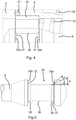
- the coupling element 1 shows an embodiment of a coupling element 1, which is designed as a coupling sleeve.
- the coupling element 1 is part of a coupling for connecting pressure medium lines, in this exemplary embodiment a hydraulic coupling.
- the coupling element 1 shown, the coupling sleeve is used for joining with a - in 2 shown - corresponding, second coupling element 1a - a coupling plug - whereby two pressure medium lines, the coupling sleeve and the coupling plug, are connected to each other.
- the coupling element 1 comprises a housing 2 , the housing 2 comprising a connection part 3 and a sliding sleeve 4 .
- the housing 2 at least partially delimits a flow channel 5 for a pressure medium.
- a valve tappet 6 is arranged centrally within the flow channel 5 .
- the valve tappet 6 is surrounded by a pressure sleeve 7 .
- the pressure sleeve 7 is slidably guided in an inner body 8 along an axis A of the clutch.
- the valve tappet 6 arranged centrally in the flow channel 5 has a valve tappet shaft 9 and a valve tappet head 10 .
- the valve tappet head 10 is expanded compared to the valve tappet shaft 9, ie it has a larger diameter.
- the pressure sleeve 7 is mounted in the inner body 8 in such a way that the pressure sleeve 7 moves along the coupling axis A between a closed position, in which the flow channel 5 is closed by the pressure sleeve 7, and an open position, in which the flow channel 5 is released by the pressure sleeve 7. is movable.
- valve tappet head 10 forms in the flat-sealing face of the coupling element - in 1 shown on the right - part of the end face.
- the flat-sealing end face of the coupling element 1 is also formed by a piston 13, a base body 14 and the sliding sleeve 4.
- the pressure sleeve 7 which is slidably held within the inner body 8 , is always urged in the direction of its closed position by a compression spring 15 , so that the pressure sleeve 7 can only be moved out of its closed position against the force of the compression spring 15 .
- the compression spring 15 also surrounds the valve tappet 6.
- This force consists in particular of the force the pressure spring 15 and a pressure-dependent component, namely the effect of the pressurized pressure medium on the pressure sleeve 7.
- the forces acting on the valve tappet 6 can lead to damage to the valve tappet 6 at very high pressures.
- the inner body 8 and the pressure sleeve 7 have means with which the force acting from the pressure sleeve 7 on the valve tappet head 10 can be limited, namely a first peripheral shoulder 16 on the inner body 8 and a second peripheral shoulder 17 on the pressure sleeve 7.
- the first step 16 represents a first stop area and the second step 17 represents a second stop area.
- the second shoulder 17 is formed in the end region oriented in the direction of the release position of the pressure sleeve 7 .
- the second shoulder 17 forms the end face 32 of the pressure sleeve 7 oriented in this direction.
- the first stop surface 18 of the first step 16 comes into contact with the second stop surface 19 of the second step 17, as a result of which force is transmitted from the pressure sleeve 7 to the inner body 8 and the force acting from the pressure sleeve 7 on the valve tappet head 10 is limited , in that part of the force is carried away by the inner body 8. For example, this state is in 2 shown.
- the force acting from the pressure sleeve 7 on the valve tappet head 10 is consequently limited in at least one operating state, in particular from at least one threshold value for the pressure within the flow channel 5, in particular divided between the valve tappet head 10 and the inner body 8 Because the first shoulder 16 and the second paragraph 17 are formed circumferentially, the power transmission can take place advantageously over the entire annular surface.
- a seal 20 is arranged between the pressure sleeve 7 and the inner body 8 .
- the seal 20 is arranged in a groove 30 formed on the inner body 8 between the first shoulder 16 and a sealing shoulder 31 .
- the sealing shoulder 31 forms the end face of the inner body 8 oriented in the direction of the valve tappet head 10.
- the inner body 8 is braced between the base body 14 and the connection part 3 , with a seal 21 being arranged between the inner body 8 and the connection part 3 .
- valve tappet 6 is held on the housing 2 via a valve tappet bearing 23 , in particular clamped between the inner body 8 and the connection part 3 .
- the valve tappet bearing 23 comprises two half-shells which engage in a groove 24 on the valve tappet 6 and thereby hold it centrally in the flow channel 5 .
- the compression spring 15 of the pressure sleeve 7 is supported on the valve tappet bearing 23 in order to bring about a force on the pressure sleeve 7 in the direction of the closed position.
- the details of a valve tappet 6 in the area of the valve tappet bearing 23 result, for example, from FIG 4 .
- a piston spring 25 is provided between the inner body 8 and the base body 14 which is screwed to the connecting part 3 and urges the piston 13 into its closed position in the flat-sealing end face of the coupling element 1 .
- the piston 13 blocks a movement of the locking balls 26, which thereby also block the sliding sleeve 4 in its release position.
- the sliding sleeve 4 is urged against the locking balls 26 by a sleeve spring 27 .
- the sliding sleeve 4 moves in the direction of its blocking position, in which movement of the blocking balls 26 is in turn blocked by a blocking surface 28 of the sliding sleeve 4 in such a way that a positive connection is established between the first coupling element 1 and the second coupling element 1a via the blocking balls 26 .
- the sliding sleeve 4 In the locked position, the sliding sleeve 4 is in contact with a limiting element is designed here as a snap ring 29.
- the sliding sleeve 4 is always loaded by the sleeve spring 27 .
- FIG. 2 shows the embodiment of the first coupling element 1 according to 1 in another operating state, namely in the operating state in which the first paragraph 16 of the inner body 8 and the second paragraph 17 of the pressure sleeve 7 have come to rest.
- this operating state present at a pressure of about 40 MPa, the force from the pressure sleeve 7 to the valve tappet head 10 is limited by the means, namely the first paragraph 16 and the second paragraph 17, in that part of the force is transmitted to the inner body 8 will.
- In 2 are the first paragraph 16 and the second paragraph 17 flat against each other.
- the second coupling element 1a comprises a connector body 40 in which a spring-loaded plunger 42 is arranged.
- An outer peripheral groove 39 is arranged in the plug body 40 and interacts with the locking balls 26 of the first coupling element 1 .
- the plunger 42 closes the flow channel 43.
- the second coupling element 1a can be introduced into the first coupling element 1 by inserting the plug body 40 into the first coupling element 1 in such a way that the piston 13 moves against the force of the piston spring 25 into the interior of the first coupling element 1 is pushed, with the pressure sleeve 7 being pushed by the piston 13 in the direction of its open position from a certain position.
- FIG 3a shows a detail of an embodiment of a coupling element in the area of the valve tappet head 10.
- the sealing surface 22 has a Inclination angle ⁇ from 0° ( ⁇ in Figure 3b not shown), so that the sealing surface 22 is oriented parallel to the clutch axis A.
- the counter-sealing surface 34 of the pressure sleeve 7 has an angle ⁇ of 35° to the clutch axis A, so that the pressure sleeve 7 only rests against one edge of the sealing surface 22 in the closed state shown, whereby an advantageous seal between the pressure sleeve 7 and the valve tappet head 10 is realized.
- a seal 11 is provided in a groove 12 in the valve tappet head 10 of the valve tappet 6 for sealing purposes.
- Figure 3b shows a section of another exemplary embodiment of a coupling element 1 not within the scope of the invention in the area of valve tappet head 10 of valve tappet 10.
- Sealing surface 22 has an angle ⁇ of 30° to clutch axis A, while counter-sealing surface 34 has an angle ⁇ of 35° to Coupling axis A has.
- the pressure sleeve 7 In the illustrated closed state of the pressure sleeve 7 , the pressure sleeve 7 consequently rests with the counter sealing surface 34 only on a peripheral edge of the sealing surface 22 .
- a seal 11 is also provided in a groove 12 for further sealing.
- the tappet guide 23 is arranged in the groove 24.
- the ram guide 23 is clamped between the inner body 8 and the connection part 3 .
- the seal 21 is arranged between the inner body 8 and the connection part.
- the groove 24 has two opposing flanks 35a and 35b, which merge into the groove base 36 via a first chamfer 37.
- the first chamfer 37 significantly reduces the stresses on the groove base 36 in the operating state, which increases operational reliability.
- the first chamfer 37 is in each case - in the present case opposite - inclined at an angle of approximately 35° to the coupling axis A and has a width of 0.45 mm.
- figure 5 shows an embodiment of a valve tappet 6 for a coupling element 1. Shown is the groove 24 with the opposing flanks 35a and 35b and the groove base 36. In the transition between the groove flanks 35a and 35b, a second chamfer 38 is arranged next to the first chamfer 37, which immediately follows the first chamfer 37. The first chamfer 37 and the second chamfer 38 have a different angle of inclination to the axis A of the coupling.
- Figure 6a shows an embodiment of a valve tappet 6 for a coupling element 1. Shown is the groove 24 with the opposing groove flanks 35a and 35b and the groove bottom 36. In the transition between the from the - in Figure 6a not shown - valve tappet head 10 facing away from the groove flank 35a is next to the first chamfer 37, a second chamfer 38 is arranged, which directly adjoins the first chamfer 37.
- the first chamfer 37 and the second chamfer 38 have a different angle of inclination to the clutch axis A or to the longitudinal axis of the valve tappet that coincides with it.
- the first chamfer 37 encloses an angle ⁇ of 45° to the coupling axis A
- the second chamfer 38 encloses an angle ⁇ of 30° to the coupling axis A.
- Figure 6b shows an embodiment of a valve tappet 6 for a coupling element 1. Shown is the groove 24 with the opposing groove flanks 35a and 35b and the groove bottom 36. In the transition between the from the - in Figure 6b A first chamfer 37 with an angle ⁇ is arranged on the groove flank 35a facing away from the valve tappet head 10 (not shown, but located on the left-hand side). The first chamfer 37 encloses an angle ⁇ of 45° to the clutch axis A or to the longitudinal axis of the valve tappet 6 that coincides with it.
Landscapes
- Engineering & Computer Science (AREA)
- General Engineering & Computer Science (AREA)
- Mechanical Engineering (AREA)
- Lift Valve (AREA)
- Safety Valves (AREA)
- Quick-Acting Or Multi-Walled Pipe Joints (AREA)
- Fuel-Injection Apparatus (AREA)
Claims (10)
- Élément d'accouplement (1) pour un accouplement destiné à relier des conduites de fluide sous pression, comprenant un corps (2), un conduit d'écoulement (5) d'un fluide sous pression, un poussoir (6) de vanne, une douille de compression (7) et un corps intérieur (8), sachant que le corps (2) présente un axe d'accouplement A, sachant que le poussoir (6) de vanne est maintenu dans le corps (2) de sorte que le poussoir (6) de vanne est disposé dans le conduit d'écoulement (5), sachant que le poussoir (6) de vanne présente une tête (10) du poussoir de vanne, sachant que la douille de compression (7) entoure le poussoir (6) de vanne, sachant que la douille de compression (7) est maintenue déplaçable le long de l'axe d'accouplement A entre une position de fermeture sur laquelle le conduit d'écoulement (5) est obturé par la douille de compression (7), et une position d'ouverture sur laquelle le conduit d'écoulement (5) est dégagé par la douille de compression (7), sachant que la douille de compression (7) applique, lorsque à l'état fermé, directement contre la tête (10) du poussoir de vanne, de sorte que parallèlement à l'axe d'accouplement A une force est transmise de la douille de compression (7) à la tête (10) du poussoir de vanne, sachant que le corps intérieur (8) et la douille de compression (7) présentent des moyens permettant de limiter la force exercée par la douille de compression (7) sur la tête (10) de poussoir de vanne, sachant que le moyen contre le corps intérieur (8) est configuré comme première zone de butée et le moyen contre la douille de compression (7) comme seconde zone de butée, sachant que la première zone de butée et la seconde zone de butée interagissent pour limiter la force, sachant que le corps (2) présente une pièce de raccordement (3) vissée avec un corps de base (14) configuré en forme de douille, qui immobilise en même temps le corps intérieur (8) contre la pièce de raccordement (3), de sorte que le corps intérieur (8), dans lequel est guidée la douille de compression (7), est serré entre le corps de base (14) et la pièce de raccordement (3), sachant qu'entre le corps intérieur (8) et la pièce de raccordement (3) est disposé un joint (21), caractérisé en ce que la tête (10) du poussoir de vanne présente une surface d'étanchéité (22) inclinée selon un angle (α) de 0° par rapport à l'axe d'accouplement A, de sorte que la surface d'étanchéité (22) est orientée parallèle à l'axe d'accouplement A, et sachant que la douille de compression (7) présente une surface d'étanchéité (34) antagoniste inclinée selon un angle (β) par rapport à l'axe d'accouplement A, sachant que la surface d'étanchéité (34) antagoniste applique au moins partiellement contre la surface d'étanchéité lorsque la douille de compression (7) se trouve en position fermée, sachant que l'angle (β) est compris entre 30° et 45°, de sorte que la surface d'étanchéité (34) antagoniste applique contre une arête de la surface d'étanchéité (22).
- Élément d'accouplement (1) selon la revendication 1, caractérisé en ce que la première zone de butée est configurée comme premier épaulement (16) contre le corps intérieur (8), et la seconde zone de butée comme second épaulement (17) contre la douille de compression (7).
- Élément d'accouplement (1) selon la revendication 2, caractérisé en ce que le diamètre intérieur du premier épaulement (16) du corps intérieur (8) est inférieur au diamètre extérieur du second épaulement (17) de la douille de compression (7).
- Élément d'accouplement (1) selon l'une des revendications 1 à 3, caractérisé en ce que la première zone de butée et la seconde zone de butée se trouvent distantes l'une de l'autre au moins lorsque la douille de compression (7) se trouve à l'état fermé hors pression.
- Élément d'accouplement (1) selon l'une des revendications 1 à 4, caractérisé en ce que la première zone de butée et la seconde zone de butée arrivent en applique au moins à partir d'une pression prédéfinie à l'intérieur du conduit d'écoulement (5), du fait d'une déformation, en fonction de la pression, du poussoir (6) de vanne et/ou de la douille de compression (7).
- Élément d'accouplement (1) selon l'une des revendications précédentes, caractérisé en ce que le poussoir (6) de vanne est maintenu contre le corps (2) via un palier (23) de poussoir, et que le palier (23) de poussoir comprend au moins deux demi-coques.
- Élément d'accouplement (1) selon la revendication 6, caractérisé en ce que le palier (23) de poussoir est disposé dans une gorge (24) contre le poussoir de vanne, que la gorge (24) présente deux flancs (35a, 35) et un fond (36) de gorge, et qu'entre au moins l'un des flancs (35a, 35b) de gorge et le fond (36) de gorge est configuré au moins un premier chanfrein (37) présentant un angle (γ) par rapport à l'axe d'accouplement A, notamment que l'angle (γ) est compris entre 30° et 60°.
- Élément d'accouplement (1) selon la revendication 7, caractérisé en ce qu'entre au moins le flanc (35a) de gorge des flancs (35a, 35b) de gorge, et le fond (36) de gorge, est configuré en plus au moins un second chanfrein (38) présentant un angle (δ) par rapport à l'axe d'accouplement A, et que le second chanfrein (38), partant du flanc (35a) de gorge se raccorde au premier chanfrein (37), notamment que l'angle (δ) est compris entre 30° et 60°.
- Élément d'accouplement (1) selon l'une des revendications précédentes, caractérisé en ce que l'élément d'accouplement (1) est configuré en manchon d'accouplement ou comme connecteur d'accouplement.
- Accouplement, notamment accouplement hydraulique, comprenant un premier élément d'accouplement (1) et un second élément d'accouplement, sachant que le premier élément d'accouplement (1) et le second élément d'accouplement sont reliables entre eux pour relier une conduite de fluide sous pression, caractérisé en ce que le premier élément d'accouplement (1) et/ou le second élément d'accouplement est/sont configuré(s) selon l'une des revendications 1 à 9.
Priority Applications (1)
| Application Number | Priority Date | Filing Date | Title |
|---|---|---|---|
| PL16795043T PL3377796T3 (pl) | 2015-11-17 | 2016-11-14 | Element łączący do złącza do łączenia przewodów medium ciśnieniowego |
Applications Claiming Priority (2)
| Application Number | Priority Date | Filing Date | Title |
|---|---|---|---|
| DE102015222640.9A DE102015222640B4 (de) | 2015-11-17 | 2015-11-17 | Kupplungselement und Ventilstößel für eine Kupplung zur Verbindung von Druckmittelleitungen |
| PCT/EP2016/077528 WO2017084992A1 (fr) | 2015-11-17 | 2016-11-14 | Élément de raccord pour un raccord destiné à relier des conduites de fluide sous pression |
Publications (2)
| Publication Number | Publication Date |
|---|---|
| EP3377796A1 EP3377796A1 (fr) | 2018-09-26 |
| EP3377796B1 true EP3377796B1 (fr) | 2022-01-26 |
Family
ID=57288429
Family Applications (1)
| Application Number | Title | Priority Date | Filing Date |
|---|---|---|---|
| EP16795043.5A Active EP3377796B1 (fr) | 2015-11-17 | 2016-11-14 | Élément de raccord pour un raccord destiné à relier des conduites de fluide sous pression |
Country Status (9)
| Country | Link |
|---|---|
| US (1) | US10767800B2 (fr) |
| EP (1) | EP3377796B1 (fr) |
| KR (1) | KR102087739B1 (fr) |
| CN (1) | CN108291681B (fr) |
| BR (1) | BR112018009578B1 (fr) |
| DE (1) | DE102015222640B4 (fr) |
| PL (1) | PL3377796T3 (fr) |
| RU (1) | RU2697914C1 (fr) |
| WO (1) | WO2017084992A1 (fr) |
Families Citing this family (6)
| Publication number | Priority date | Publication date | Assignee | Title |
|---|---|---|---|---|
| GB2559209A (en) * | 2017-01-27 | 2018-08-01 | Eaton Sas | Flat face female hydraulic coupling |
| DE102017126459B4 (de) * | 2017-11-10 | 2021-07-08 | U.M. Gewerbeimmobilien Gmbh & Co. Kg | Kupplungselement für eine Hydraulikkupplung |
| DE102017128022A1 (de) * | 2017-11-27 | 2019-05-29 | Airbus Operations Gmbh | Kupplungssystem zum Bereitstellen mehrerer Fluidverbindungen |
| KR102037070B1 (ko) * | 2017-12-18 | 2019-11-26 | 주식회사 아이제이 | 건식 차단 커플링 |
| CN110081251B (zh) * | 2019-05-09 | 2021-08-20 | 爱发科东方真空(成都)有限公司 | 一种扩口管自封型密封接头 |
| FR3101389B1 (fr) * | 2019-09-30 | 2021-10-22 | Staubli Sa Ets | Raccord fluidique |
Citations (1)
| Publication number | Priority date | Publication date | Assignee | Title |
|---|---|---|---|---|
| US20040079423A1 (en) * | 2002-10-25 | 2004-04-29 | Toshio Mikiya | Fluid coupler |
Family Cites Families (13)
| Publication number | Priority date | Publication date | Assignee | Title |
|---|---|---|---|---|
| SU446715A2 (ru) * | 1972-12-02 | 1974-10-15 | Предприятие П/Я Г-4213 | Пневматический разъем дл подсоединени узлов и агрегатов к пневматическим источникам питани |
| US4447040A (en) * | 1983-04-20 | 1984-05-08 | Systron-Donner | Fluid line coupling with relief valve |
| DE8809220U1 (de) | 1988-07-19 | 1988-09-01 | Dreesbeimdieke, Hermann, 4830 Gütersloh | Schnellverschlußkupplung für Hydraulikleitungen |
| NZ323175A (en) | 1995-11-20 | 1998-10-28 | Aeroquip Corp | Female coupling designed for low spill during connection or disconnection |
| US5709243A (en) * | 1995-11-20 | 1998-01-20 | Aeroquip Corporation | Low spill female coupling |
| CN2318495Y (zh) * | 1997-10-22 | 1999-05-12 | 尹国雄 | 液化气钢瓶气口快换接头 |
| ITMI20011415A1 (it) | 2001-07-04 | 2003-01-04 | Faster Srl | Innesto rapido a faccia piana perfezionato |
| JP2003113981A (ja) * | 2001-10-02 | 2003-04-18 | Smc Corp | カプラー |
| WO2003096444A2 (fr) * | 2002-05-13 | 2003-11-20 | University Of Florida | Reseau et systeme mems resonants comprenant un processeur d'energie pouvant etre modifie de façon dynamique |
| CN2934850Y (zh) * | 2006-06-27 | 2007-08-15 | 曹振海 | 高压连接器 |
| TW200949121A (en) * | 2008-02-28 | 2009-12-01 | Nitto Kohki Co | Socket for pipe coupling and pipe coupling |
| IT1396544B1 (it) | 2008-07-24 | 2012-12-14 | Faster Spa | Innesto rapido con recupero dei giochi interni |
| DE102010019094A1 (de) * | 2010-04-30 | 2011-11-03 | Rheinisch-Westfälische Technische Hochschule Aachen | Hydraulikkupplungsmuffe |
-
2015
- 2015-11-17 DE DE102015222640.9A patent/DE102015222640B4/de active Active
-
2016
- 2016-11-14 US US15/776,852 patent/US10767800B2/en active Active
- 2016-11-14 RU RU2018117365A patent/RU2697914C1/ru active
- 2016-11-14 PL PL16795043T patent/PL3377796T3/pl unknown
- 2016-11-14 EP EP16795043.5A patent/EP3377796B1/fr active Active
- 2016-11-14 CN CN201680064406.3A patent/CN108291681B/zh active Active
- 2016-11-14 WO PCT/EP2016/077528 patent/WO2017084992A1/fr active Application Filing
- 2016-11-14 BR BR112018009578-8A patent/BR112018009578B1/pt active IP Right Grant
- 2016-11-14 KR KR1020187013088A patent/KR102087739B1/ko active IP Right Grant
Patent Citations (1)
| Publication number | Priority date | Publication date | Assignee | Title |
|---|---|---|---|---|
| US20040079423A1 (en) * | 2002-10-25 | 2004-04-29 | Toshio Mikiya | Fluid coupler |
Also Published As
| Publication number | Publication date |
|---|---|
| DE102015222640B4 (de) | 2021-08-26 |
| US20180328526A1 (en) | 2018-11-15 |
| CN108291681B (zh) | 2020-12-08 |
| WO2017084992A1 (fr) | 2017-05-26 |
| KR20180081514A (ko) | 2018-07-16 |
| DE102015222640A1 (de) | 2017-05-18 |
| US10767800B2 (en) | 2020-09-08 |
| CN108291681A (zh) | 2018-07-17 |
| EP3377796A1 (fr) | 2018-09-26 |
| RU2697914C1 (ru) | 2019-08-21 |
| BR112018009578B1 (pt) | 2022-01-11 |
| PL3377796T3 (pl) | 2022-05-16 |
| KR102087739B1 (ko) | 2020-03-12 |
| BR112018009578A2 (pt) | 2018-11-06 |
Similar Documents
| Publication | Publication Date | Title |
|---|---|---|
| EP3377796B1 (fr) | Élément de raccord pour un raccord destiné à relier des conduites de fluide sous pression | |
| EP2909519B1 (fr) | Accouplement coaxial à haute pression avec décharge de surpression | |
| DE202011050262U1 (de) | Spannvorrichtung für ein Werkstück oder Werkzeug | |
| DE102014010570A1 (de) | Kupplungsteil für eine Kupplung für Druckmittelleitungen | |
| DE69714713T2 (de) | Schnellkupplung für unter druck stehende rohre oder schläuche | |
| DE102013102384B4 (de) | Koaxiale Hochdruckkupplung mit beim Kupplungsvorgang wirksamer Abdichtung von Steckerteil und Aufnahmeteil | |
| EP2672161B1 (fr) | Raccordement rapide pour conduits sous pression hydraulique | |
| EP2505895A1 (fr) | Elément de raccordement d'un raccord de conduit à moyen de pression | |
| EP1707863B9 (fr) | Pièce de raccord pour un raccord enfichable pour fluide sous pression | |
| EP3688238A1 (fr) | Dispositif anti-reflux et séparateur de système en particulier pour le domaine de la lutte contre les incendies | |
| DE202011004778U1 (de) | Kupplungsteil einer Druckmittel-Leitungskupplung | |
| EP3926226B1 (fr) | Élément d'accouplement pour un accouplement hydraulique | |
| DE102017128022A1 (de) | Kupplungssystem zum Bereitstellen mehrerer Fluidverbindungen | |
| DE202011004779U1 (de) | Schnellkupplung für Hydraulik-Druckleitungen | |
| WO2011057702A1 (fr) | Soupape présentant une protection contre le démontage et une aide au montage | |
| EP3230639B1 (fr) | Élément de raccordement destiné à un raccordement à vis pour des conduites de fluide de pression | |
| EP3816495B1 (fr) | Raccord à sertir | |
| DE102012105399A1 (de) | Rohrverbindung | |
| EP2476939A2 (fr) | Raccord pour le raccordement d'une extrémité de tuyau | |
| EP3081837B1 (fr) | Raccord enfichable pour conduites | |
| DE3039072A1 (de) | Auch unter druck kuppelbare schnellverschlusskupplung | |
| DE19543567A1 (de) | Vorrichtung für die Verbindung zwischen einem aufnehmenden und einem eindringenden Teil, insbesondere für die Verbindung eines Gewinderings mit einem Rohrelement | |
| EP4390207A1 (fr) | Pièce d'accouplement pour un accouplement hydraulique | |
| EP3181972A1 (fr) | Raccord à vis pour la liaison amovible de conduites hydrauliques haute pression | |
| DE29806088U1 (de) | Steckkupplung zum Verbinden von Kabeln, Schläuchen o.dgl. |
Legal Events
| Date | Code | Title | Description |
|---|---|---|---|
| STAA | Information on the status of an ep patent application or granted ep patent |
Free format text: STATUS: UNKNOWN |
|
| STAA | Information on the status of an ep patent application or granted ep patent |
Free format text: STATUS: THE INTERNATIONAL PUBLICATION HAS BEEN MADE |
|
| PUAI | Public reference made under article 153(3) epc to a published international application that has entered the european phase |
Free format text: ORIGINAL CODE: 0009012 |
|
| STAA | Information on the status of an ep patent application or granted ep patent |
Free format text: STATUS: REQUEST FOR EXAMINATION WAS MADE |
|
| 17P | Request for examination filed |
Effective date: 20180426 |
|
| AK | Designated contracting states |
Kind code of ref document: A1 Designated state(s): AL AT BE BG CH CY CZ DE DK EE ES FI FR GB GR HR HU IE IS IT LI LT LU LV MC MK MT NL NO PL PT RO RS SE SI SK SM TR |
|
| AX | Request for extension of the european patent |
Extension state: BA ME |
|
| DAV | Request for validation of the european patent (deleted) | ||
| DAX | Request for extension of the european patent (deleted) | ||
| STAA | Information on the status of an ep patent application or granted ep patent |
Free format text: STATUS: EXAMINATION IS IN PROGRESS |
|
| 17Q | First examination report despatched |
Effective date: 20190606 |
|
| STAA | Information on the status of an ep patent application or granted ep patent |
Free format text: STATUS: EXAMINATION IS IN PROGRESS |
|
| GRAP | Despatch of communication of intention to grant a patent |
Free format text: ORIGINAL CODE: EPIDOSNIGR1 |
|
| STAA | Information on the status of an ep patent application or granted ep patent |
Free format text: STATUS: GRANT OF PATENT IS INTENDED |
|
| INTG | Intention to grant announced |
Effective date: 20211012 |
|
| GRAS | Grant fee paid |
Free format text: ORIGINAL CODE: EPIDOSNIGR3 |
|
| GRAA | (expected) grant |
Free format text: ORIGINAL CODE: 0009210 |
|
| STAA | Information on the status of an ep patent application or granted ep patent |
Free format text: STATUS: THE PATENT HAS BEEN GRANTED |
|
| AK | Designated contracting states |
Kind code of ref document: B1 Designated state(s): AL AT BE BG CH CY CZ DE DK EE ES FI FR GB GR HR HU IE IS IT LI LT LU LV MC MK MT NL NO PL PT RO RS SE SI SK SM TR |
|
| REG | Reference to a national code |
Ref country code: GB Ref legal event code: FG4D Free format text: NOT ENGLISH |
|
| REG | Reference to a national code |
Ref country code: CH Ref legal event code: EP |
|
| REG | Reference to a national code |
Ref country code: AT Ref legal event code: REF Ref document number: 1465535 Country of ref document: AT Kind code of ref document: T Effective date: 20220215 |
|
| REG | Reference to a national code |
Ref country code: IE Ref legal event code: FG4D Free format text: LANGUAGE OF EP DOCUMENT: GERMAN |
|
| REG | Reference to a national code |
Ref country code: DE Ref legal event code: R096 Ref document number: 502016014467 Country of ref document: DE |
|
| REG | Reference to a national code |
Ref country code: FI Ref legal event code: FGE |
|
| REG | Reference to a national code |
Ref country code: NL Ref legal event code: FP |
|
| REG | Reference to a national code |
Ref country code: SE Ref legal event code: TRGR |
|
| REG | Reference to a national code |
Ref country code: LT Ref legal event code: MG9D |
|
| PG25 | Lapsed in a contracting state [announced via postgrant information from national office to epo] |
Ref country code: RS Free format text: LAPSE BECAUSE OF FAILURE TO SUBMIT A TRANSLATION OF THE DESCRIPTION OR TO PAY THE FEE WITHIN THE PRESCRIBED TIME-LIMIT Effective date: 20220126 Ref country code: PT Free format text: LAPSE BECAUSE OF FAILURE TO SUBMIT A TRANSLATION OF THE DESCRIPTION OR TO PAY THE FEE WITHIN THE PRESCRIBED TIME-LIMIT Effective date: 20220526 Ref country code: NO Free format text: LAPSE BECAUSE OF FAILURE TO SUBMIT A TRANSLATION OF THE DESCRIPTION OR TO PAY THE FEE WITHIN THE PRESCRIBED TIME-LIMIT Effective date: 20220426 Ref country code: LT Free format text: LAPSE BECAUSE OF FAILURE TO SUBMIT A TRANSLATION OF THE DESCRIPTION OR TO PAY THE FEE WITHIN THE PRESCRIBED TIME-LIMIT Effective date: 20220126 Ref country code: HR Free format text: LAPSE BECAUSE OF FAILURE TO SUBMIT A TRANSLATION OF THE DESCRIPTION OR TO PAY THE FEE WITHIN THE PRESCRIBED TIME-LIMIT Effective date: 20220126 Ref country code: ES Free format text: LAPSE BECAUSE OF FAILURE TO SUBMIT A TRANSLATION OF THE DESCRIPTION OR TO PAY THE FEE WITHIN THE PRESCRIBED TIME-LIMIT Effective date: 20220126 Ref country code: BG Free format text: LAPSE BECAUSE OF FAILURE TO SUBMIT A TRANSLATION OF THE DESCRIPTION OR TO PAY THE FEE WITHIN THE PRESCRIBED TIME-LIMIT Effective date: 20220426 |
|
| PG25 | Lapsed in a contracting state [announced via postgrant information from national office to epo] |
Ref country code: LV Free format text: LAPSE BECAUSE OF FAILURE TO SUBMIT A TRANSLATION OF THE DESCRIPTION OR TO PAY THE FEE WITHIN THE PRESCRIBED TIME-LIMIT Effective date: 20220126 Ref country code: GR Free format text: LAPSE BECAUSE OF FAILURE TO SUBMIT A TRANSLATION OF THE DESCRIPTION OR TO PAY THE FEE WITHIN THE PRESCRIBED TIME-LIMIT Effective date: 20220427 |
|
| PG25 | Lapsed in a contracting state [announced via postgrant information from national office to epo] |
Ref country code: IS Free format text: LAPSE BECAUSE OF FAILURE TO SUBMIT A TRANSLATION OF THE DESCRIPTION OR TO PAY THE FEE WITHIN THE PRESCRIBED TIME-LIMIT Effective date: 20220526 |
|
| REG | Reference to a national code |
Ref country code: DE Ref legal event code: R097 Ref document number: 502016014467 Country of ref document: DE |
|
| PG25 | Lapsed in a contracting state [announced via postgrant information from national office to epo] |
Ref country code: SM Free format text: LAPSE BECAUSE OF FAILURE TO SUBMIT A TRANSLATION OF THE DESCRIPTION OR TO PAY THE FEE WITHIN THE PRESCRIBED TIME-LIMIT Effective date: 20220126 Ref country code: SK Free format text: LAPSE BECAUSE OF FAILURE TO SUBMIT A TRANSLATION OF THE DESCRIPTION OR TO PAY THE FEE WITHIN THE PRESCRIBED TIME-LIMIT Effective date: 20220126 Ref country code: RO Free format text: LAPSE BECAUSE OF FAILURE TO SUBMIT A TRANSLATION OF THE DESCRIPTION OR TO PAY THE FEE WITHIN THE PRESCRIBED TIME-LIMIT Effective date: 20220126 Ref country code: EE Free format text: LAPSE BECAUSE OF FAILURE TO SUBMIT A TRANSLATION OF THE DESCRIPTION OR TO PAY THE FEE WITHIN THE PRESCRIBED TIME-LIMIT Effective date: 20220126 Ref country code: DK Free format text: LAPSE BECAUSE OF FAILURE TO SUBMIT A TRANSLATION OF THE DESCRIPTION OR TO PAY THE FEE WITHIN THE PRESCRIBED TIME-LIMIT Effective date: 20220126 Ref country code: CZ Free format text: LAPSE BECAUSE OF FAILURE TO SUBMIT A TRANSLATION OF THE DESCRIPTION OR TO PAY THE FEE WITHIN THE PRESCRIBED TIME-LIMIT Effective date: 20220126 |
|
| PG25 | Lapsed in a contracting state [announced via postgrant information from national office to epo] |
Ref country code: AL Free format text: LAPSE BECAUSE OF FAILURE TO SUBMIT A TRANSLATION OF THE DESCRIPTION OR TO PAY THE FEE WITHIN THE PRESCRIBED TIME-LIMIT Effective date: 20220126 |
|
| PLBE | No opposition filed within time limit |
Free format text: ORIGINAL CODE: 0009261 |
|
| STAA | Information on the status of an ep patent application or granted ep patent |
Free format text: STATUS: NO OPPOSITION FILED WITHIN TIME LIMIT |
|
| 26N | No opposition filed |
Effective date: 20221027 |
|
| PG25 | Lapsed in a contracting state [announced via postgrant information from national office to epo] |
Ref country code: SI Free format text: LAPSE BECAUSE OF FAILURE TO SUBMIT A TRANSLATION OF THE DESCRIPTION OR TO PAY THE FEE WITHIN THE PRESCRIBED TIME-LIMIT Effective date: 20220126 |
|
| P01 | Opt-out of the competence of the unified patent court (upc) registered |
Effective date: 20230513 |
|
| PG25 | Lapsed in a contracting state [announced via postgrant information from national office to epo] |
Ref country code: MC Free format text: LAPSE BECAUSE OF FAILURE TO SUBMIT A TRANSLATION OF THE DESCRIPTION OR TO PAY THE FEE WITHIN THE PRESCRIBED TIME-LIMIT Effective date: 20220126 |
|
| PG25 | Lapsed in a contracting state [announced via postgrant information from national office to epo] |
Ref country code: LU Free format text: LAPSE BECAUSE OF NON-PAYMENT OF DUE FEES Effective date: 20221114 |
|
| PGFP | Annual fee paid to national office [announced via postgrant information from national office to epo] |
Ref country code: NL Payment date: 20231122 Year of fee payment: 8 |
|
| PGFP | Annual fee paid to national office [announced via postgrant information from national office to epo] |
Ref country code: GB Payment date: 20231123 Year of fee payment: 8 |
|
| PGFP | Annual fee paid to national office [announced via postgrant information from national office to epo] |
Ref country code: SE Payment date: 20231123 Year of fee payment: 8 Ref country code: IT Payment date: 20231130 Year of fee payment: 8 Ref country code: IE Payment date: 20231117 Year of fee payment: 8 Ref country code: FR Payment date: 20231122 Year of fee payment: 8 Ref country code: FI Payment date: 20231120 Year of fee payment: 8 Ref country code: DE Payment date: 20231107 Year of fee payment: 8 Ref country code: CH Payment date: 20231202 Year of fee payment: 8 Ref country code: AT Payment date: 20231117 Year of fee payment: 8 |
|
| PGFP | Annual fee paid to national office [announced via postgrant information from national office to epo] |
Ref country code: PL Payment date: 20231107 Year of fee payment: 8 Ref country code: BE Payment date: 20231121 Year of fee payment: 8 |
|
| PG25 | Lapsed in a contracting state [announced via postgrant information from national office to epo] |
Ref country code: HU Free format text: LAPSE BECAUSE OF FAILURE TO SUBMIT A TRANSLATION OF THE DESCRIPTION OR TO PAY THE FEE WITHIN THE PRESCRIBED TIME-LIMIT; INVALID AB INITIO Effective date: 20161114 |
|
| PG25 | Lapsed in a contracting state [announced via postgrant information from national office to epo] |
Ref country code: CY Free format text: LAPSE BECAUSE OF FAILURE TO SUBMIT A TRANSLATION OF THE DESCRIPTION OR TO PAY THE FEE WITHIN THE PRESCRIBED TIME-LIMIT Effective date: 20220126 |
|
| PG25 | Lapsed in a contracting state [announced via postgrant information from national office to epo] |
Ref country code: MK Free format text: LAPSE BECAUSE OF FAILURE TO SUBMIT A TRANSLATION OF THE DESCRIPTION OR TO PAY THE FEE WITHIN THE PRESCRIBED TIME-LIMIT Effective date: 20220126 |