EP3377796B1 - Coupling element for a coupling for connecting pressure medium lines - Google Patents
Coupling element for a coupling for connecting pressure medium lines Download PDFInfo
- Publication number
- EP3377796B1 EP3377796B1 EP16795043.5A EP16795043A EP3377796B1 EP 3377796 B1 EP3377796 B1 EP 3377796B1 EP 16795043 A EP16795043 A EP 16795043A EP 3377796 B1 EP3377796 B1 EP 3377796B1
- Authority
- EP
- European Patent Office
- Prior art keywords
- valve tappet
- coupling
- coupling element
- pressure sleeve
- pressure
- Prior art date
- Legal status (The legal status is an assumption and is not a legal conclusion. Google has not performed a legal analysis and makes no representation as to the accuracy of the status listed.)
- Active
Links
- 238000010168 coupling process Methods 0.000 title claims description 170
- 230000008878 coupling Effects 0.000 title claims description 169
- 238000005859 coupling reaction Methods 0.000 title claims description 169
- 238000007789 sealing Methods 0.000 claims description 33
- 230000001419 dependent effect Effects 0.000 claims description 4
- 230000000903 blocking effect Effects 0.000 description 12
- 230000006835 compression Effects 0.000 description 10
- 238000007906 compression Methods 0.000 description 10
- 230000007704 transition Effects 0.000 description 9
- 230000002829 reductive effect Effects 0.000 description 8
- 230000002093 peripheral effect Effects 0.000 description 7
- 230000000670 limiting effect Effects 0.000 description 6
- 230000008901 benefit Effects 0.000 description 5
- 230000000694 effects Effects 0.000 description 4
- 239000000463 material Substances 0.000 description 4
- 230000005540 biological transmission Effects 0.000 description 3
- 238000010276 construction Methods 0.000 description 3
- 230000006378 damage Effects 0.000 description 2
- 230000009471 action Effects 0.000 description 1
- 230000009172 bursting Effects 0.000 description 1
- 230000000981 bystander Effects 0.000 description 1
- 238000004140 cleaning Methods 0.000 description 1
- 238000007667 floating Methods 0.000 description 1
- 238000005304 joining Methods 0.000 description 1
- 238000004519 manufacturing process Methods 0.000 description 1
- 230000036961 partial effect Effects 0.000 description 1
- 230000009467 reduction Effects 0.000 description 1
- 230000000284 resting effect Effects 0.000 description 1
- 230000000717 retained effect Effects 0.000 description 1
- 239000000725 suspension Substances 0.000 description 1
Images


Classifications
-
- F—MECHANICAL ENGINEERING; LIGHTING; HEATING; WEAPONS; BLASTING
- F16—ENGINEERING ELEMENTS AND UNITS; GENERAL MEASURES FOR PRODUCING AND MAINTAINING EFFECTIVE FUNCTIONING OF MACHINES OR INSTALLATIONS; THERMAL INSULATION IN GENERAL
- F16L—PIPES; JOINTS OR FITTINGS FOR PIPES; SUPPORTS FOR PIPES, CABLES OR PROTECTIVE TUBING; MEANS FOR THERMAL INSULATION IN GENERAL
- F16L37/00—Couplings of the quick-acting type
- F16L37/22—Couplings of the quick-acting type in which the connection is maintained by means of balls, rollers or helical springs under radial pressure between the parts
- F16L37/23—Couplings of the quick-acting type in which the connection is maintained by means of balls, rollers or helical springs under radial pressure between the parts by means of balls
-
- F—MECHANICAL ENGINEERING; LIGHTING; HEATING; WEAPONS; BLASTING
- F16—ENGINEERING ELEMENTS AND UNITS; GENERAL MEASURES FOR PRODUCING AND MAINTAINING EFFECTIVE FUNCTIONING OF MACHINES OR INSTALLATIONS; THERMAL INSULATION IN GENERAL
- F16L—PIPES; JOINTS OR FITTINGS FOR PIPES; SUPPORTS FOR PIPES, CABLES OR PROTECTIVE TUBING; MEANS FOR THERMAL INSULATION IN GENERAL
- F16L37/00—Couplings of the quick-acting type
- F16L37/28—Couplings of the quick-acting type with fluid cut-off means
- F16L37/30—Couplings of the quick-acting type with fluid cut-off means with fluid cut-off means in each of two pipe-end fittings
- F16L37/32—Couplings of the quick-acting type with fluid cut-off means with fluid cut-off means in each of two pipe-end fittings at least one of two lift valves being opened automatically when the coupling is applied
- F16L37/34—Couplings of the quick-acting type with fluid cut-off means with fluid cut-off means in each of two pipe-end fittings at least one of two lift valves being opened automatically when the coupling is applied at least one of the lift valves being of the sleeve type, i.e. a sleeve is telescoped over an inner cylindrical wall
-
- Y—GENERAL TAGGING OF NEW TECHNOLOGICAL DEVELOPMENTS; GENERAL TAGGING OF CROSS-SECTIONAL TECHNOLOGIES SPANNING OVER SEVERAL SECTIONS OF THE IPC; TECHNICAL SUBJECTS COVERED BY FORMER USPC CROSS-REFERENCE ART COLLECTIONS [XRACs] AND DIGESTS
- Y10—TECHNICAL SUBJECTS COVERED BY FORMER USPC
- Y10T—TECHNICAL SUBJECTS COVERED BY FORMER US CLASSIFICATION
- Y10T137/00—Fluid handling
- Y10T137/8593—Systems
- Y10T137/87917—Flow path with serial valves and/or closures
- Y10T137/87925—Separable flow path section, valve or closure in each
- Y10T137/87941—Each valve and/or closure operated by coupling motion
- Y10T137/87949—Linear motion of flow path sections operates both
Definitions
- the invention relates to a coupling element for a coupling, in particular a hydraulic coupling, for connecting pressure medium lines according to the preamble of patent claim 1.
- Coupling elements for couplings are known in the prior art in a large number of configurations.
- Hydraulic couplings namely a combination of coupling sleeve and coupling plug, are used to connect two sections of a pressure medium line and are often used to connect hydraulic equipment to a hydraulic source, for example to connect a tool or attachment to an agricultural machine or a construction machine.
- Coupling elements are known from the prior art in which the flow channel is closed by a centrally mounted pressure sleeve, in that the pressure sleeve bears at least indirectly against the valve tappet head of the valve tappet in its closed position.
- a seal is arranged between the valve tappet head and the pressure sleeve.
- EP 1 273 844 B1 such a hydraulic coupling with a coupling element is known in which a pressure sleeve rests against the valve tappet head of a valve tappet to close a flow channel.
- the pressure sleeve is loaded with a spring in the direction of its closed position and interacts at least partially with the valve tappet head via a seal.
- the pressure sleeve is moved from its closed position in the direction of its release position under the action of a plugged into a coupling sleeve, for example, coupling plug, whereby the flow channel is released.
- a movement of the pressure sleeve from the closed position to the release position takes place always against the force of the spring, which pushes the pressure sleeve into its closed position.
- the pressure sleeve rests against the valve tappet head and exerts a force on the valve tappet parallel to the coupling axis of the coupling element.
- This force is made up of, among other things, the spring force on the pressure sleeve and the pressure-dependent forces on the pressure sleeve in the direction of your closed position. More coupling elements are in the U.S. 2004/079423 A1 described.
- the coupling elements known from the prior art have the risk that at very high pressures, in particular when the bursting pressure of the coupling element is reached, parts of the coupling element will become detached or tear off, which poses a safety risk for bystanders.
- the present invention is therefore based on the object of specifying a coupling element and a valve tappet in which the safety for users is increased, but at the same time the operating properties of the coupling element are retained or improved.
- limiting always means both an absolute limitation to a fixed threshold value and a percentage reduction in the force.
- the coupling element is part of a coupling, in particular a hydraulic coupling, for connecting pressure medium lines and is designed, for example, as a coupling socket or as a coupling plug.
- a coupling comprises a coupling sleeve and a coupling plug, the coupling plug being inserted into the coupling sleeve in order to connect the flow channels of the coupling sleeve and the coupling plug to one another connect to.
- the coupling element preferably has a nominal diameter of 19, 16 or 12.5.
- the coupling element can be connected to a corresponding, second coupling element, for example via a screw or snap-in connection.
- the coupling element includes a housing, a flow channel for a pressure medium, a valve tappet, a pressure sleeve and an inner body.
- the housing of the coupling element has a central coupling axis A, which extends between a first end of the coupling element, to which a pressure medium line can be connected, and a second end, to which the connection to the other coupling element of a coupling takes place.
- the components of the coupling element are preferably designed to be rotationally symmetrical about the coupling axis A.
- the inner body or, in the case of a coupling sleeve the inner body is designed to be rotationally symmetrical and sleeve-like.
- displaceable components of the coupling element are preferably always displaced parallel to the coupling axis A.
- the housing delimits at least part of the flow channel, with the further course of the flow channel being advantageously delimited by the further components of the coupling element.
- the flow channel is delimited at least by the housing, the inner body and the pressure sleeve.
- the housing has a connecting part and preferably a sliding sleeve.
- the connection part is screwed to a base body, with the base body simultaneously fixing the inner body on the connection part.
- the base body is also designed like a sleeve.
- a seal is arranged between the inner body and the connection part, in particular on an end face of the inner body.
- the external sliding sleeve is on the body between a release position and held slidably in a locked position.
- the base body in turn surrounds the inner body.
- a plurality of peripheral recesses is preferably provided in the base body, in which locking elements, in particular locking balls, are arranged.
- the blocking elements are arranged in the recesses of the base body and interact with an associated inner peripheral groove in the sliding sleeve in such a way that the sliding sleeve is held in its release position in a form-fitting manner.
- a sleeve spring for example, is arranged between the base body and the sliding sleeve, which spring pushes the sliding sleeve in its release position against the blocking elements in the direction of the blocking position of the sliding sleeve. In this state, further movement of the sliding sleeve is prevented by the blocking elements.
- the coupling element also includes a piston which is guided within the base body and which prevents movement of the blocking elements when the sliding sleeve is in the release position.
- the piston is displaced in the direction of the inner body, from a certain position of the piston the blocking of the blocking elements is initially taken over by a region of the second coupling element until the blocking balls can move into an outer circumferential groove of the second coupling element.
- the locking sleeve the movement of which is now released, is urged into its locking position by the sleeve spring, with the locking elements then being blocked by a locking surface of the sliding sleeve.
- the sliding sleeve moves until it rests against a delimiting element arranged on the base body—locked position of the sliding sleeve.
- the limiting element is designed, for example, as a snap ring arranged in the base body—in its outer circumference.
- the sliding sleeve In order to separate the coupling elements of a coupling connected in this way, the sliding sleeve must be manually pushed into its release position against the force of the sleeve spring, which allows the locking elements to move back into the inner circumferential groove of the locking sleeve and thus enable the second coupling element to be disengaged.
- valve tappet is held within the coupling element in such a way that the valve tappet is arranged centrally in the flow channel. Consequently, the flow channel surrounds the valve tappet arranged in the flow channel, so that in particular the shaft of the valve tappet and the valve tappet head are surrounded by the pressure medium during operation.
- the valve tappet head is preferably part of the flat-sealing face at the second end of the coupling element.
- the valve stem is arranged in such a way that it is surrounded by the inner body and the pressure sleeve.
- the pressure sleeve is preferably guided inside the inner body, which is fixed or floating to the housing, in such a way that the pressure sleeve moves parallel to the clutch axis A between a closed position, in which the flow channel is closed by the pressure sleeve, and an open position, in which the flow channel is closed by the pressure sleeve is released, can be moved.
- a compression spring is provided which exerts a force on the compression sleeve in the direction of its closed position, so that the compression sleeve is always urged into its closed position by the compression spring.
- a seal is preferably always provided between the pressure sleeve and the valve tappet head.
- the seal is arranged, for example, in a circumferential groove in the valve tappet head.
- the seal is preferably in contact with an inner circumference of the pressure sleeve.
- the pressure sleeve is designed and arranged so that it bears against the valve tappet head in such a way that a force parallel to the clutch axis A of the pressure sleeve acts on the valve tappet head.
- This force consists in particular of the force acting on the pressure sleeve from the compression spring and of force components that result from the pressurized pressure medium present in the flow channel, which acts on the pressure sleeve and causes a force on the pressure sleeve in the direction of the valve tappet head.
- valve tappet When pressure is present in the closed flow channel, the valve tappet is consequently loaded on the one hand by the pressure acting on it and on the other hand by the force emanating from the pressure sleeve.
- the stem of the valve tappet With increasing pressure within the flow channel, the stem of the valve tappet lengthens, for example, due to the axial tensile stresses, which can lead to a tearing off of the valve tappet head or the valve tappet in the area of the stem or in the area of the suspension of the valve tappet if the force on the valve tappet is not reduced.
- the inner body and/or the pressure sleeve has means with which the force can be limited. It is provided, for example, that the means on the inner body and/or on the pressure sleeve act in such a way that the force of the pressure sleeve on the valve tappet head is limited by at least some of the force or forces being transmitted from the pressure sleeve to the inner body. The forces are transferred from the inner body to the housing. The limitation of the force reliably prevents the valve tappet from being destroyed, thereby increasing the operational reliability of the coupling element.
- the means on the inner body and/or on the pressure sleeve are designed in such a way that the force acting on the valve tappet head is limited or reduced in at least one operating state of the coupling element.
- the force acting on the valve tappet head from the pressure sleeve is limited or reduced from a predetermined threshold value of the pressure within the coupling element with the means or means.
- Usual operating pressures for a coupling element are between 25 MPa and 40 MPa, in particular the operating pressure is 35 MPa. It is preferably provided that the predetermined threshold value of the pressure within the clutch element, from which the force is limited or reduced with the means or means, is in the range between the operating pressure and 4 times the operating pressure, in particular between 1.5 -and twice the operating pressure.
- means for limiting the force from the pressure sleeve to the valve tappet head are provided both on the inner body and on the pressure sleeve.
- the means are in particular designed and set up in such a way that the means on the inner body and the means on the pressure sleeve interact in order to limit or reduce the force from the pressure sleeve on the valve tappet head.
- the coupling element according to the invention has the advantage that the risk of overloading the valve tappet is reduced by the means, in that the force acting on it from the pressure sleeve is limited with the means in at least one operating state, in particular from at least one operating state, resulting in destruction of the valve lifter is prevented.
- the forces emanating from the pressure sleeve are divided between the valve tappet head and the inner body by the means.
- the coupling element according to the invention also has the advantage that the same operating parameters, eg. B. operating pressure and burst pressure can be achieved, as in known constructions. There is also the advantage that with the same materials as higher operating parameters can be achieved with known constructions and even increased operating parameters with higher-quality materials. Provision is made for the means on the inner body to be in the form of a first stop area and the means on the pressure sleeve to be in the form of a second stop area, with the first stop area and the second stop area cooperating to limit the force on the valve tappet, in particular the valve tappet head.
- the same operating parameters eg. B. operating pressure and burst pressure
- the pressure sleeve is guided inside the inner body.
- a stop area is provided on the inner body and on the pressure sleeve.
- the first stop area and the second stop area come into contact in at least one operating state, in particular from at least one operating state, of the coupling element, so that force can be transmitted from the pressure sleeve to the inner body, whereby part of the forces acting on the pressure sleeve in the direction of the valve tappet head is transmitted via the first stop area or the second stop area from the inner body attached to the housing.
- the force acting on the valve tappet from the pressure sleeve is limited, which is advantageous in particular at high pressures, in particular pressures above the operating pressure, within the closed flow channel.
- the first stop area and the second stop area are designed, for example, as local projections that extend from the inner body or the pressure sleeve.
- a plurality of regularly distributed projections are preferably provided, which form the first stop area or the second stop area.
- the first stop area is provided as a first step on the inner body and the second stop area as a second step is formed on the pressure sleeve.
- the first shoulder on the inner body and the second shoulder on the pressure sleeve are advantageously formed circumferentially, so that a uniform transmission of force from the pressure sleeve to the inner body can take place over the entire circumference of the two shoulders.
- the first step and the second step have corresponding contact surfaces, so that the force from the pressure sleeve on the valve tappet can be limited by contact of the contact surfaces.
- the corresponding contact surfaces are preferably formed orthogonally to the coupling axis of the coupling element.
- the first projection is formed on the end region of the inner body oriented in the direction of the valve tappet head and preferably has a rectangular cross section.
- a further sealing shoulder is advantageously formed on the inner body, and a seal is arranged between the first shoulder and the sealing shoulder, which seal acts between an inner circumference of the inner body and an outer circumference of the pressure sleeve.
- the second shoulder is preferably formed on the end region of the pressure sleeve that is oriented in the direction of the opening position of the pressure sleeve.
- the second paragraph has a rectangular cross-section.
- the second shoulder forms at least a part of the annular end face of the pressure sleeve oriented in the direction of the release position of the pressure sleeve.
- the transition between the inner circumference of the pressure sleeve and the end face has a radius or a chamfer.
- the radius is between 1 mm and 2 mm, in particular 1.5 mm.
- a further embodiment of the coupling element provides that the first stop area and the second stop area are spaced apart from one another at least in the pressureless closed state of the pressure sleeve—uncoupled state.
- the length of the pressure sleeve is preferably selected in such a way that the pressure sleeve rests against the valve tappet head in the closed state, the first stop area and the second stop area being spaced apart from one another at the same time.
- An increasing pressure within the flow channel leads to an elongation of the valve tappet, in particular in the area of the shaft, and a widening of the pressure sleeve, with both effects leading to the first stop area and the second stop area resting against one another above a certain threshold value of the pressure within the flow channel and partial power transmission occurs to the inner body, thereby limiting the force from the compression sleeve to the valve stem head.
- the threshold value is preferably in a range between the operating pressure and four times the operating pressure, in particular between 1.5 and 2 times the operating pressure, with the operating pressure preferably being between 25 MPa and 40 MPa.
- the first stop area and the second stop area are consequently designed and arranged in such a way that the force is limited at least above a predetermined pressure within the flow channel, in particular a pressure between 35 MPa and 70 MPa.
- the first stop area and the second stop area consequently come into contact only above a predetermined pressure within the flow channel.
- the first stop area is not in contact with the second stop area and the pressure sleeve is supported exclusively on the valve tappet head.
- a further embodiment therefore provides that the first stop area and the second stop area come into contact at least at a predetermined pressure within the flow channel by a pressure-dependent deformation of the valve tappet and/or the pressure sleeve.
- the pressure varies from which an elastic and/or plastic deformation of the components takes place.
- the materials are selected such that above a predetermined pressure the valve tappet and/or the pressure sleeve are deformed in such a way that the first stop area and the second stop area come into contact, thereby limiting the force on the valve tappet head.
- the valve tappet, the pressure sleeve and the inner body are preferably deformed in the elastic range.
- this pressure is between the operating pressure and four times the operating pressure, in particular between 1.5 and twice the operating pressure.
- a seal is advantageously provided between the valve tappet head and the pressure sleeve, which seal adjoins the sealing surface and rests against an inner circumference of the pressure sleeve in the closed position.
- Such a conical seal between the valve tappet head and the pressure sleeve has the advantage that the flow channel is opened even with a small stroke of the pressure sleeve, which reduces the flow losses in the clutch.
- the conical seal is simple and robust against tolerance fluctuations.
- a further advantage is that the gap that results for a seal provided on the valve tappet head on the non-pressure side can be minimized or completely closed with a conical seal between the valve tappet head and the pressure sleeve, even when utilizing normal manufacturing tolerances.
- the sealing effect can be increased by providing that ⁇ and ⁇ are different, with ⁇ being smaller than ⁇ .
- valve tappet can advantageously be installed within the coupling element if, according to a further embodiment, the valve tappet is held on the housing via a tappet bearing, and the tappet bearing comprises at least two half-shells. In its shaft, the valve tappet has a circumferential groove into which the half-shells are at least partially inserted. The valve tappet with the inserted half-shells is then mounted inside the housing, in particular in such a way that the valve tappet is held between the inner body and the connecting part of the housing.
- the tappet bearing is arranged in a groove on the valve tappet, the groove having two opposite groove flanks and a groove base.
- the flanks of the groove are preferably formed orthogonally to the coupling axis A and the bottom of the groove parallel thereto.
- At least one first chamfer with an angle ⁇ to the coupling axis A is formed between at least one of the groove flanks and the groove base, ie in the region of the transition from the groove flank to the groove base.
- At least one chamfer is preferably provided between the groove flank facing away from the valve tappet head and the groove bottom.
- the angle ⁇ is advantageously between 30° and 60°.
- the bevel particularly preferably has an angle ⁇ of 35° with a width of 0.45 mm (35° ⁇ 0.45).
- a radius is provided between the groove flank, on which no chamfer is provided, and the groove base.
- At least one chamfer with the angle ⁇ to the clutch axis A or to the longitudinal axis of the valve tappet that coincides with the clutch axis A is provided in the transition from each of the two groove flanks to the groove base.
- a second chamfer with an angle ( ⁇ ) to the coupling axis A is formed between the at least one groove flank of the two groove flanks and the groove bottom, and that the second Starting from the groove flank, the chamfer connects to the first chamfer.
- the transition to the bottom of the groove is initially formed by the first chamfer and then the second chamfer.
- the first chamfer and the second chamfer are provided on the groove flank facing away from the valve tappet head.
- the angle ⁇ of the first bevel is preferably greater than the angle ⁇ of the second bevel. In particular, the angle ⁇ is between 30° and 60°. It is also particularly preferred to provide at least one third chamfer or at least one third chamfer and one fourth chamfer in the transition region of the at least one groove flank to the groove base.
- At least one first chamfer and at least one second chamfer is provided in the transition region of both groove flanks to the groove base.
- the loss of pressure medium during the coupling process of a coupling with a coupling element can be reduced in a simple manner if it is provided that the coupling element is designed with a flat seal, ie all components of the coupling element at the second end of the coupling element lie in one plane. This prevents the ingress of dirt, simplifies cleaning of the coupling element and minimizes the loss of pressure medium.
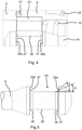
- the coupling element 1 shows an embodiment of a coupling element 1, which is designed as a coupling sleeve.
- the coupling element 1 is part of a coupling for connecting pressure medium lines, in this exemplary embodiment a hydraulic coupling.
- the coupling element 1 shown, the coupling sleeve is used for joining with a - in 2 shown - corresponding, second coupling element 1a - a coupling plug - whereby two pressure medium lines, the coupling sleeve and the coupling plug, are connected to each other.
- the coupling element 1 comprises a housing 2 , the housing 2 comprising a connection part 3 and a sliding sleeve 4 .
- the housing 2 at least partially delimits a flow channel 5 for a pressure medium.
- a valve tappet 6 is arranged centrally within the flow channel 5 .
- the valve tappet 6 is surrounded by a pressure sleeve 7 .
- the pressure sleeve 7 is slidably guided in an inner body 8 along an axis A of the clutch.
- the valve tappet 6 arranged centrally in the flow channel 5 has a valve tappet shaft 9 and a valve tappet head 10 .
- the valve tappet head 10 is expanded compared to the valve tappet shaft 9, ie it has a larger diameter.
- the pressure sleeve 7 is mounted in the inner body 8 in such a way that the pressure sleeve 7 moves along the coupling axis A between a closed position, in which the flow channel 5 is closed by the pressure sleeve 7, and an open position, in which the flow channel 5 is released by the pressure sleeve 7. is movable.
- valve tappet head 10 forms in the flat-sealing face of the coupling element - in 1 shown on the right - part of the end face.
- the flat-sealing end face of the coupling element 1 is also formed by a piston 13, a base body 14 and the sliding sleeve 4.
- the pressure sleeve 7 which is slidably held within the inner body 8 , is always urged in the direction of its closed position by a compression spring 15 , so that the pressure sleeve 7 can only be moved out of its closed position against the force of the compression spring 15 .
- the compression spring 15 also surrounds the valve tappet 6.
- This force consists in particular of the force the pressure spring 15 and a pressure-dependent component, namely the effect of the pressurized pressure medium on the pressure sleeve 7.
- the forces acting on the valve tappet 6 can lead to damage to the valve tappet 6 at very high pressures.
- the inner body 8 and the pressure sleeve 7 have means with which the force acting from the pressure sleeve 7 on the valve tappet head 10 can be limited, namely a first peripheral shoulder 16 on the inner body 8 and a second peripheral shoulder 17 on the pressure sleeve 7.
- the first step 16 represents a first stop area and the second step 17 represents a second stop area.
- the second shoulder 17 is formed in the end region oriented in the direction of the release position of the pressure sleeve 7 .
- the second shoulder 17 forms the end face 32 of the pressure sleeve 7 oriented in this direction.
- the first stop surface 18 of the first step 16 comes into contact with the second stop surface 19 of the second step 17, as a result of which force is transmitted from the pressure sleeve 7 to the inner body 8 and the force acting from the pressure sleeve 7 on the valve tappet head 10 is limited , in that part of the force is carried away by the inner body 8. For example, this state is in 2 shown.
- the force acting from the pressure sleeve 7 on the valve tappet head 10 is consequently limited in at least one operating state, in particular from at least one threshold value for the pressure within the flow channel 5, in particular divided between the valve tappet head 10 and the inner body 8 Because the first shoulder 16 and the second paragraph 17 are formed circumferentially, the power transmission can take place advantageously over the entire annular surface.
- a seal 20 is arranged between the pressure sleeve 7 and the inner body 8 .
- the seal 20 is arranged in a groove 30 formed on the inner body 8 between the first shoulder 16 and a sealing shoulder 31 .
- the sealing shoulder 31 forms the end face of the inner body 8 oriented in the direction of the valve tappet head 10.
- the inner body 8 is braced between the base body 14 and the connection part 3 , with a seal 21 being arranged between the inner body 8 and the connection part 3 .
- valve tappet 6 is held on the housing 2 via a valve tappet bearing 23 , in particular clamped between the inner body 8 and the connection part 3 .
- the valve tappet bearing 23 comprises two half-shells which engage in a groove 24 on the valve tappet 6 and thereby hold it centrally in the flow channel 5 .
- the compression spring 15 of the pressure sleeve 7 is supported on the valve tappet bearing 23 in order to bring about a force on the pressure sleeve 7 in the direction of the closed position.
- the details of a valve tappet 6 in the area of the valve tappet bearing 23 result, for example, from FIG 4 .
- a piston spring 25 is provided between the inner body 8 and the base body 14 which is screwed to the connecting part 3 and urges the piston 13 into its closed position in the flat-sealing end face of the coupling element 1 .
- the piston 13 blocks a movement of the locking balls 26, which thereby also block the sliding sleeve 4 in its release position.
- the sliding sleeve 4 is urged against the locking balls 26 by a sleeve spring 27 .
- the sliding sleeve 4 moves in the direction of its blocking position, in which movement of the blocking balls 26 is in turn blocked by a blocking surface 28 of the sliding sleeve 4 in such a way that a positive connection is established between the first coupling element 1 and the second coupling element 1a via the blocking balls 26 .
- the sliding sleeve 4 In the locked position, the sliding sleeve 4 is in contact with a limiting element is designed here as a snap ring 29.
- the sliding sleeve 4 is always loaded by the sleeve spring 27 .
- FIG. 2 shows the embodiment of the first coupling element 1 according to 1 in another operating state, namely in the operating state in which the first paragraph 16 of the inner body 8 and the second paragraph 17 of the pressure sleeve 7 have come to rest.
- this operating state present at a pressure of about 40 MPa, the force from the pressure sleeve 7 to the valve tappet head 10 is limited by the means, namely the first paragraph 16 and the second paragraph 17, in that part of the force is transmitted to the inner body 8 will.
- In 2 are the first paragraph 16 and the second paragraph 17 flat against each other.
- the second coupling element 1a comprises a connector body 40 in which a spring-loaded plunger 42 is arranged.
- An outer peripheral groove 39 is arranged in the plug body 40 and interacts with the locking balls 26 of the first coupling element 1 .
- the plunger 42 closes the flow channel 43.
- the second coupling element 1a can be introduced into the first coupling element 1 by inserting the plug body 40 into the first coupling element 1 in such a way that the piston 13 moves against the force of the piston spring 25 into the interior of the first coupling element 1 is pushed, with the pressure sleeve 7 being pushed by the piston 13 in the direction of its open position from a certain position.
- FIG 3a shows a detail of an embodiment of a coupling element in the area of the valve tappet head 10.
- the sealing surface 22 has a Inclination angle ⁇ from 0° ( ⁇ in Figure 3b not shown), so that the sealing surface 22 is oriented parallel to the clutch axis A.
- the counter-sealing surface 34 of the pressure sleeve 7 has an angle ⁇ of 35° to the clutch axis A, so that the pressure sleeve 7 only rests against one edge of the sealing surface 22 in the closed state shown, whereby an advantageous seal between the pressure sleeve 7 and the valve tappet head 10 is realized.
- a seal 11 is provided in a groove 12 in the valve tappet head 10 of the valve tappet 6 for sealing purposes.
- Figure 3b shows a section of another exemplary embodiment of a coupling element 1 not within the scope of the invention in the area of valve tappet head 10 of valve tappet 10.
- Sealing surface 22 has an angle ⁇ of 30° to clutch axis A, while counter-sealing surface 34 has an angle ⁇ of 35° to Coupling axis A has.
- the pressure sleeve 7 In the illustrated closed state of the pressure sleeve 7 , the pressure sleeve 7 consequently rests with the counter sealing surface 34 only on a peripheral edge of the sealing surface 22 .
- a seal 11 is also provided in a groove 12 for further sealing.
- the tappet guide 23 is arranged in the groove 24.
- the ram guide 23 is clamped between the inner body 8 and the connection part 3 .
- the seal 21 is arranged between the inner body 8 and the connection part.
- the groove 24 has two opposing flanks 35a and 35b, which merge into the groove base 36 via a first chamfer 37.
- the first chamfer 37 significantly reduces the stresses on the groove base 36 in the operating state, which increases operational reliability.
- the first chamfer 37 is in each case - in the present case opposite - inclined at an angle of approximately 35° to the coupling axis A and has a width of 0.45 mm.
- figure 5 shows an embodiment of a valve tappet 6 for a coupling element 1. Shown is the groove 24 with the opposing flanks 35a and 35b and the groove base 36. In the transition between the groove flanks 35a and 35b, a second chamfer 38 is arranged next to the first chamfer 37, which immediately follows the first chamfer 37. The first chamfer 37 and the second chamfer 38 have a different angle of inclination to the axis A of the coupling.
- Figure 6a shows an embodiment of a valve tappet 6 for a coupling element 1. Shown is the groove 24 with the opposing groove flanks 35a and 35b and the groove bottom 36. In the transition between the from the - in Figure 6a not shown - valve tappet head 10 facing away from the groove flank 35a is next to the first chamfer 37, a second chamfer 38 is arranged, which directly adjoins the first chamfer 37.
- the first chamfer 37 and the second chamfer 38 have a different angle of inclination to the clutch axis A or to the longitudinal axis of the valve tappet that coincides with it.
- the first chamfer 37 encloses an angle ⁇ of 45° to the coupling axis A
- the second chamfer 38 encloses an angle ⁇ of 30° to the coupling axis A.
- Figure 6b shows an embodiment of a valve tappet 6 for a coupling element 1. Shown is the groove 24 with the opposing groove flanks 35a and 35b and the groove bottom 36. In the transition between the from the - in Figure 6b A first chamfer 37 with an angle ⁇ is arranged on the groove flank 35a facing away from the valve tappet head 10 (not shown, but located on the left-hand side). The first chamfer 37 encloses an angle ⁇ of 45° to the clutch axis A or to the longitudinal axis of the valve tappet 6 that coincides with it.
Description
Die Erfindung betrifft ein Kupplungselement für eine Kupplung, insbesondere eine Hydraulikkupplung, zur Verbindung von Druckmittelleitungen gemäß dem Oberbegriff des Patentanspruchs 1.The invention relates to a coupling element for a coupling, in particular a hydraulic coupling, for connecting pressure medium lines according to the preamble of
Kupplungselemente für Kupplungen, insbesondere für Hydraulikkupplungen, sind im Stand der Technik in einer Vielzahl von Ausgestaltungen bekannt. Hydraulikkupplungen, nämlich eine Kombination aus Kupplungsmuffe und Kupplungsstecker, dienen dem Verbinden von zwei Abschnitten einer Druckmittelleitung und werden oftmals dazu verwendet, hydraulische Geräte an eine Hydraulikquelle anzuschließen, beispielsweise zum Anschließen eines Werkzeugs oder Anbaugeräts an eine landwirtschaftliche Maschine oder eine Baumaschine.Coupling elements for couplings, in particular for hydraulic couplings, are known in the prior art in a large number of configurations. Hydraulic couplings, namely a combination of coupling sleeve and coupling plug, are used to connect two sections of a pressure medium line and are often used to connect hydraulic equipment to a hydraulic source, for example to connect a tool or attachment to an agricultural machine or a construction machine.
Aus dem Stand der Technik sind Kupplungselemente bekannt, bei denen der Strömungskanal durch eine zentral gelagerte Druckhülse verschlossen wird, indem die Druckhülse in ihrer Schließposition zumindest mittelbar an dem Ventilstößelkopf des Ventilstößels anliegt. Dabei ist zwischen Ventilstößelkopf und der Druckhülse eine Dichtung angeordnet.Coupling elements are known from the prior art in which the flow channel is closed by a centrally mounted pressure sleeve, in that the pressure sleeve bears at least indirectly against the valve tappet head of the valve tappet in its closed position. A seal is arranged between the valve tappet head and the pressure sleeve.
Beispielsweise aus
Um gemäß
Die aus dem Stand der Technik bekannten Kupplungselemente weisen dabei das Risiko auf, dass bei sehr hohen Drücken, insbesondere bei Erreichen des Berstdruckes des Kupplungselements, Teile von dem Kupplungselement gelöst werden oder abreißen, wodurch ein Sicherheitsrisiko für umstehende Personen besteht.The coupling elements known from the prior art have the risk that at very high pressures, in particular when the bursting pressure of the coupling element is reached, parts of the coupling element will become detached or tear off, which poses a safety risk for bystanders.
Der vorliegenden Erfindung liegt deshalb die Aufgabe zugrunde, ein Kupplungselement und einen Ventilstößel anzugeben, bei dem die Sicherheit für Benutzer gesteigert ist, gleichzeitig aber die Betriebseigenschaften des Kupplungselements beibehalten oder verbessert werden.The present invention is therefore based on the object of specifying a coupling element and a valve tappet in which the safety for users is increased, but at the same time the operating properties of the coupling element are retained or improved.
Die vorgenannte Aufgabe ist bei einem gattungsgemäßen Kupplungselement durch die Merkmale des Anspruchs gelöst, wobei der Innenkörper und die Druckhülse Mittel aufweisen, mit denen die von der Druckhülse auf den Ventilstößelkopf wirkende Kraft begrenzbar ist bzw. die wirkenden Kräfte begrenzbar sind. Begrenzen bedeutet in diesem Zusammenhang stets sowohl eine absolute Begrenzung auf einen festen Schwellenwert als auch eine prozentuale Reduzierung der Kraft.The aforementioned object is achieved in a generic coupling element by the features of the claim, the inner body and the pressure sleeve having means with which the force acting from the pressure sleeve on the valve tappet head can be limited or the acting forces can be limited. In this context, limiting always means both an absolute limitation to a fixed threshold value and a percentage reduction in the force.
Das Kupplungselement ist ein Teil einer Kupplung, insbesondere einer Hydraulikkupplung, zur Verbindung von Druckmittelleitungen und ist beispielsweise als Kupplungsmuffe oder als Kupplungsstecker ausgebildet. Eine Kupplung umfasst dabei jeweils eine Kupplungsmuffe und einen Kupplungsstecker, wobei der Kupplungsstecker in die Kupplungsmuffe eingesteckt wird, um die Strömungskanäle der Kupplungsmuffe und des Kupplungssteckers miteinander zu verbinden. Das Kupplungselement hat vorzugsweise eine Nennweite von 19, 16 oder 12,5.The coupling element is part of a coupling, in particular a hydraulic coupling, for connecting pressure medium lines and is designed, for example, as a coupling socket or as a coupling plug. A coupling comprises a coupling sleeve and a coupling plug, the coupling plug being inserted into the coupling sleeve in order to connect the flow channels of the coupling sleeve and the coupling plug to one another connect to. The coupling element preferably has a nominal diameter of 19, 16 or 12.5.
Das Kupplungselement ist beispielsweise über eine Schraub- oder Rastverbindung mit einem korrespondierenden, zweiten Kuppelelement verbindbar. Das Kupplungselement umfasst ein Gehäuse, einen Strömungskanal für ein Druckmittel, einen Ventilstößel, eine Druckhülse und einen Innenkörper.The coupling element can be connected to a corresponding, second coupling element, for example via a screw or snap-in connection. The coupling element includes a housing, a flow channel for a pressure medium, a valve tappet, a pressure sleeve and an inner body.
Das Gehäuse des Kupplungselements weist eine zentrale Kupplungsachse A auf, die sich zwischen einem ersten Ende des Kupplungselements, an dem eine Druckmittelleitung anschließbar ist, und einem zweiten Ende, an dem die Verbindung mit dem weiteren Kupplungselement einer Kupplung erfolgt, erstreckt. Vorzugsweise sind die Bauelemente des Kupplungselements rotationssymmetrisch um die Kupplungsachse A ausgebildet. Beispielsweise ist der Innenkörper oder im Falle einer Kupplungsmuffe der Innenkörper rotationssymmetrisch und hülsenartig ausgebildet. Bevorzugt erfolgt ferner eine Verschiebung von verschiebbaren Bauelementen des Kupplungselements stets parallel zur Kupplungsachse A.The housing of the coupling element has a central coupling axis A, which extends between a first end of the coupling element, to which a pressure medium line can be connected, and a second end, to which the connection to the other coupling element of a coupling takes place. The components of the coupling element are preferably designed to be rotationally symmetrical about the coupling axis A. For example, the inner body or, in the case of a coupling sleeve, the inner body is designed to be rotationally symmetrical and sleeve-like. Furthermore, displaceable components of the coupling element are preferably always displaced parallel to the coupling axis A.
Insbesondere begrenzt das Gehäuse zumindest einen Teil des Strömungskanals, wobei der weitere Verlauf des Strömungskanals vorteilhaft durch die weiteren Bauteile des Kupplungselements begrenzt wird. Beispielsweise wird der Strömungskanal zumindest durch das Gehäuse, den Innenkörper und die Druckhülse begrenzt.In particular, the housing delimits at least part of the flow channel, with the further course of the flow channel being advantageously delimited by the further components of the coupling element. For example, the flow channel is delimited at least by the housing, the inner body and the pressure sleeve.
Das Gehäuse weist ein Anschlussteil und vorzugsweise eine Schiebehülse auf. Das Anschlussteil ist mit einem Grundkörper verschraubt, wobei der Grundkörper gleichzeitig den Innenkörper am Anschlussteil festlegt. Der Grundkörper ist ebenfalls hülsenartig ausgebildet. Eine Dichtung ist zwischen Innenkörper und Anschlussteil angeordnet, insbesondere an einer Stirnfläche des Innenkörpers. Die außenliegende Schiebehülse ist auf dem Grundkörper zwischen einer Freigabeposition und einer Sperrposition verschiebbar gehalten. Der Grundkörper umgibt wiederum den Innenkörper.The housing has a connecting part and preferably a sliding sleeve. The connection part is screwed to a base body, with the base body simultaneously fixing the inner body on the connection part. The base body is also designed like a sleeve. A seal is arranged between the inner body and the connection part, in particular on an end face of the inner body. The external sliding sleeve is on the body between a release position and held slidably in a locked position. The base body in turn surrounds the inner body.
In dem Grundkörper ist vorzugsweise eine Vielzahl von umlaufenden Ausnehmungen vorgesehen, in denen Sperrelemente, insbesondere Sperrkugeln, angeordnet sind. Die Sperrelemente sind im Freigabezustand in den Ausnehmungen des Grundkörpers angeordnet und wirken mit einer zugehörigen Innenumfangsnut in der Schiebhülse derart zusammen, dass die Schiebehülse formschlüssig in ihrer Freigabeposition gehalten wird. Zwischen dem Grundkörper und der Schiebehülse ist beispielsweise eine Hülsenfeder angeordnet, die die Schiebehülse in ihrer Freigabeposition gegen die Sperrelemente, in Richtung der Sperrposition der Schiebehülse drängt. Eine weitere Bewegung der Schiebehülse wird in diesem Zustand durch die Sperrelemente verhindert. Das Kupplungselement umfasst zudem einen Kolben, der innerhalb des Grundkörpers geführt ist, und der in der Freigabeposition der Schiebehülse eine Bewegung der Sperrelemente verhindert.A plurality of peripheral recesses is preferably provided in the base body, in which locking elements, in particular locking balls, are arranged. In the released state, the blocking elements are arranged in the recesses of the base body and interact with an associated inner peripheral groove in the sliding sleeve in such a way that the sliding sleeve is held in its release position in a form-fitting manner. A sleeve spring, for example, is arranged between the base body and the sliding sleeve, which spring pushes the sliding sleeve in its release position against the blocking elements in the direction of the blocking position of the sliding sleeve. In this state, further movement of the sliding sleeve is prevented by the blocking elements. The coupling element also includes a piston which is guided within the base body and which prevents movement of the blocking elements when the sliding sleeve is in the release position.
Wird nun, beispielsweise durch Einbringen eines korrespondierenden, zweiten Kupplungselements in das erste Kupplungselement, z. B. eines Kupplungssteckers in eine Kupplungsmuffe, der Kolben in Richtung des Innenkörpers verschoben, wird ab einer bestimmten Position des Kolbens die Sperrung der Sperrelemente zunächst von einem Bereich des zweiten Kupplungselements übernommen, bis die Sperrkugeln in eine Außenumfangsnut des zweiten Kupplungselements ausweichen können. In diesem Moment wird die Sperrhülse, deren Bewegung nunmehr freigegeben ist, durch die Hülsenfeder in ihre Rastposition gedrängt, wobei die Sperrelemente anschließend durch eine Sperrfläche der Schiebehülse blockiert werden. Die Schiebehülse bewegt sich dabei soweit, bis sie an einem am Grundkörper angeordneten Begrenzungselement anliegt- Sperrposition der Schiebehülse. Das Begrenzungselement ist beispielsweise als ein im Grundkörper - in dessen Außenumfang - angeordneter Sprengring ausgebildet.If now, for example, by introducing a corresponding, second coupling element in the first coupling element, z. B. a coupling plug in a coupling sleeve, the piston is displaced in the direction of the inner body, from a certain position of the piston the blocking of the blocking elements is initially taken over by a region of the second coupling element until the blocking balls can move into an outer circumferential groove of the second coupling element. At this moment, the locking sleeve, the movement of which is now released, is urged into its locking position by the sleeve spring, with the locking elements then being blocked by a locking surface of the sliding sleeve. The sliding sleeve moves until it rests against a delimiting element arranged on the base body—locked position of the sliding sleeve. The limiting element is designed, for example, as a snap ring arranged in the base body—in its outer circumference.
Um die derart verbundenen Kupplungselemente einer Kupplung voneinander zu trennen, muss die Schiebehülse manuell entgegen der Kraft der Hülsenfeder in ihre Freigabeposition verschoben werden, wodurch die Sperrelemente wieder in die Innenumfangsnut der Sperrhülse ausweichen können und so ein Auskuppeln des zweiten Kuppelelements ermöglichen.In order to separate the coupling elements of a coupling connected in this way, the sliding sleeve must be manually pushed into its release position against the force of the sleeve spring, which allows the locking elements to move back into the inner circumferential groove of the locking sleeve and thus enable the second coupling element to be disengaged.
Der Ventilstößel ist innerhalb des Kupplungselements derart gehalten, dass der Ventilstößel zentral im Strömungskanal angeordnet ist. Folglich umgibt der Strömungskanal den im Strömungskanal angeordneten Ventilstößel, so dass insbesondere der Schaft des Ventilstößels und der Ventilstößelkopf von dem Druckmittel im Betrieb umströmt werden. Der Ventilstößelkopf ist bevorzugt Teil der flachdichtenden Stirnfläche am zweiten Ende des Kupplungselements.The valve tappet is held within the coupling element in such a way that the valve tappet is arranged centrally in the flow channel. Consequently, the flow channel surrounds the valve tappet arranged in the flow channel, so that in particular the shaft of the valve tappet and the valve tappet head are surrounded by the pressure medium during operation. The valve tappet head is preferably part of the flat-sealing face at the second end of the coupling element.
Der Ventilstößel ist derart angeordnet, dass er von dem Innenkörper und der Druckhülse umgeben wird. Die Druckhülse ist vorzugsweise innerhalb des mit dem Gehäuse fest oder schwimmend verbundenen Innenkörpers derart geführt, dass sich die Druckhülse parallel zur Kupplungsachse A zwischen einer Schließposition, in der der Strömungskanal durch die Druckhülse verschlossen wird, und einer Öffnungsposition, in der der Strömungskanal durch die Druckhülse freigegeben wird, verschieben lässt. Insbesondere ist eine Druckfeder vorgesehen, die eine Kraft auf die Druckhülse in Richtung Ihrer Schließposition bewirkt, so dass die Druckhülse durch die Druckfeder stets in ihre Schließposition gedrängt wird.The valve stem is arranged in such a way that it is surrounded by the inner body and the pressure sleeve. The pressure sleeve is preferably guided inside the inner body, which is fixed or floating to the housing, in such a way that the pressure sleeve moves parallel to the clutch axis A between a closed position, in which the flow channel is closed by the pressure sleeve, and an open position, in which the flow channel is closed by the pressure sleeve is released, can be moved. In particular, a compression spring is provided which exerts a force on the compression sleeve in the direction of its closed position, so that the compression sleeve is always urged into its closed position by the compression spring.
In der Schließposition der Druckhülse erfolgt ein Verschließen des Strömungskanals dadurch, dass die Druckhülse unmittelbar an dem Ventilstößelkopf anliegt. Vorzugsweise ist stets eine Dichtung zwischen Druckhülse und Ventilstößelkopf vorgesehen. Die Dichtung ist beispielsweise in einer umlaufenden Nut im Ventilstößelkopf angeordnet. Die Dichtung liegt vorzugsweise an einem Innenumfang der Druckhülse an.In the closed position of the pressure sleeve, the flow channel is closed in that the pressure sleeve bears directly against the valve tappet head. A seal is preferably always provided between the pressure sleeve and the valve tappet head. The seal is arranged, for example, in a circumferential groove in the valve tappet head. The seal is preferably in contact with an inner circumference of the pressure sleeve.
Die Druckhülse ist so ausgebildet und angeordnet, dass sie derart an dem Ventilstößelkopf anliegt, dass eine Kraft parallel zur Kupplungsachse A von der Druckhülse auf den Ventilstößelkopf wirkt. Diese Kraft setzt sich insbesondere zusammen aus der von der Druckfeder auf die Druckhülse wirkenden Kraft und aus Kraftanteilen, die aus im Strömungskanal vorhandenem, unter Druck stehendem Druckmittel resultieren, das auf die Druckhülse wirkt und eine Kraft auf die Druckhülse in Richtung des Ventilstößelkopfes verursacht.The pressure sleeve is designed and arranged so that it bears against the valve tappet head in such a way that a force parallel to the clutch axis A of the pressure sleeve acts on the valve tappet head. This force consists in particular of the force acting on the pressure sleeve from the compression spring and of force components that result from the pressurized pressure medium present in the flow channel, which acts on the pressure sleeve and causes a force on the pressure sleeve in the direction of the valve tappet head.
Bei anliegendem Druck im geschlossenen Strömungskanal wird der Ventilstößel folglich einerseits durch den auf ihn wirkenden Druck, andererseits durch die von der Druckhülse ausgehende Kraft belastet. Bei steigendem Druck innerhalb des Strömungskanals längt sich beispielsweise der Schaft des Ventilstößels durch die axialen Zugspannungen was bei unverminderter Kraft auf den Ventilstößel zu einem Abreißen des Ventilstößelkopfes oder des Ventilstößels im Bereich des Schaftes oder im Bereich der Aufhängung des Ventilstößels führen kann.When pressure is present in the closed flow channel, the valve tappet is consequently loaded on the one hand by the pressure acting on it and on the other hand by the force emanating from the pressure sleeve. With increasing pressure within the flow channel, the stem of the valve tappet lengthens, for example, due to the axial tensile stresses, which can lead to a tearing off of the valve tappet head or the valve tappet in the area of the stem or in the area of the suspension of the valve tappet if the force on the valve tappet is not reduced.
Um die von der Druckhülse auf den Ventilstößel wirkende Kraft bzw. die Kräfte, insbesondere in Richtung parallel zur Kupplungsachse A, zu begrenzen, weist der Innenkörper und/oder die Druckhülse Mittel auf, mit denen die Kraft begrenzbar ist. Es ist beispielsweise vorgesehen, dass die Mittel am Innenkörper und/oder an der Druckhülse derart wirken, dass die Kraft der Druckhülse auf den Ventilstößelkopf begrenzt wird, indem zumindest ein Teil der Kraft bzw. der Kräfte von der Druckhülse auf den Innenkörper übertragen werden. Von dem Innenkörper werden die Kräfte auf das Gehäuse übertragen. Durch die Begrenzung der Kraft wird eine Zerstörung des Ventilstößels zuverlässig verhindert und damit die Betriebssicherheit des Kupplungselements gesteigert.In order to limit the force or forces acting from the pressure sleeve on the valve tappet, in particular in the direction parallel to the clutch axis A, the inner body and/or the pressure sleeve has means with which the force can be limited. It is provided, for example, that the means on the inner body and/or on the pressure sleeve act in such a way that the force of the pressure sleeve on the valve tappet head is limited by at least some of the force or forces being transmitted from the pressure sleeve to the inner body. The forces are transferred from the inner body to the housing. The limitation of the force reliably prevents the valve tappet from being destroyed, thereby increasing the operational reliability of the coupling element.
Insbesondere ist vorgesehen, dass die Mittel am Innenkörper und/oder an der Druckhülse derart ausgebildet sind, dass die auf den Ventilstößelkopf wirkende Kraft in mindestens einem Betriebszustand des Kupplungselements begrenzt bzw. reduziert wird. Beispielsweise ist vorgesehen, dass die von der Druckhülse auf den Ventilstößelkopf wirkende Kraft ab einem vorbestimmten Schwellenwert des Drucks innerhalb des Kupplungselements mit dem Mittel bzw. den Mitteln begrenzt oder reduziert wird.In particular, it is provided that the means on the inner body and/or on the pressure sleeve are designed in such a way that the force acting on the valve tappet head is limited or reduced in at least one operating state of the coupling element. For example, it is provided that the force acting on the valve tappet head from the pressure sleeve is limited or reduced from a predetermined threshold value of the pressure within the coupling element with the means or means.
Übliche Betriebsdrücke für ein Kupplungselement liegen zwischen 25 MPa und 40 MPa, insbesondere ist der Betriebsdruck 35 MPa. Vorzugsweise ist vorgesehen, dass der vorbestimmte Schwellenwert des Drucks innerhalb des Kupplungselements, ab dem mit dem Mittel bzw. den Mitteln die Kraft begrenzt oder reduziert wird, im Bereich zwischen dem Betriebsdruck und dem 4-fachen des Betriebsdrucks liegt, insbesondere zwischen dem 1,5-und dem 2-fachen des Betriebsdrucks.Usual operating pressures for a coupling element are between 25 MPa and 40 MPa, in particular the operating pressure is 35 MPa. It is preferably provided that the predetermined threshold value of the pressure within the clutch element, from which the force is limited or reduced with the means or means, is in the range between the operating pressure and 4 times the operating pressure, in particular between 1.5 -and twice the operating pressure.
Nach der Erfindung sind sowohl am Innenkörper als auch an der Druckhülse Mittel zur Begrenzung der Kraft von der Druckhülse auf den Ventilstößelkopf vorgesehen. Die Mittel sind insbesondere derart ausgebildet und eingerichtet, dass die Mittel am Innenkörper und die Mittel an der Druckhülse zusammenwirken, um die Kraft von der Druckhülse auf den Ventilstößelkopf zu begrenzen bzw. zu reduzieren.According to the invention, means for limiting the force from the pressure sleeve to the valve tappet head are provided both on the inner body and on the pressure sleeve. The means are in particular designed and set up in such a way that the means on the inner body and the means on the pressure sleeve interact in order to limit or reduce the force from the pressure sleeve on the valve tappet head.
Vorteilhaft ist vorgesehen, dass die Mittel am Innenkörper und/oder die Mittel an der Druckhülse derart ausgebildet und eingerichtet sind, dass mit den Mitteln eine Bewegung der Druckhülse in Richtung des Ventilstößelkopfes begrenzbar ist.Provision is advantageously made for the means on the inner body and/or the means on the pressure sleeve to be designed and set up in such a way that the means can be used to limit a movement of the pressure sleeve in the direction of the valve tappet head.
Das erfindungsgemäße Kupplungselement weist den Vorteil auf, dass durch die Mittel das Risiko einer Überlastung des Ventilstößels reduziert wird, indem die auf ihn wirkende Kraft von der Druckhülse in mindestens einem Betriebszustand, insbesondere ab mindestens einem Betriebszustand, mit den Mitteln begrenzt wird, wodurch eine Zerstörung des Ventilstößels verhindert wird. Durch die Mittel werden die von der Druckhülse ausgehenden Kräfte auf den Ventilstößelkopf und den Innenkörper aufgeteilt.The coupling element according to the invention has the advantage that the risk of overloading the valve tappet is reduced by the means, in that the force acting on it from the pressure sleeve is limited with the means in at least one operating state, in particular from at least one operating state, resulting in destruction of the valve lifter is prevented. The forces emanating from the pressure sleeve are divided between the valve tappet head and the inner body by the means.
Das erfindungsgemäße Kupplungselement weist zudem den Vorteil auf, dass mit kostengünstigeren Werkstoffen die gleichen Betriebsparameter, z. B. Betriebsdruck und Berstdruck, erreicht werden können, wie bei bekannten Konstruktionen. Ferner besteht der Vorteil, dass mit den gleichen Werkstoffen wie bei bekannten Konstruktionen höhere Betriebsparameter erreicht werden können und mit höherwertigen Werkstoffen sogar gesteigerte Betriebsparameter. Es ist vorgesehen, dass das Mittel am Innenkörper als erster Anschlagbereich und das Mittel an der Druckhülse als zweiter Anschlagbereich ausgebildet ist, wobei der erste Anschlagbereich und der zweite Anschlagbereich zur Begrenzung der Kraft auf den Ventilstößel, insbesondere den Ventilstößelkopf, zusammenwirken.The coupling element according to the invention also has the advantage that the same operating parameters, eg. B. operating pressure and burst pressure can be achieved, as in known constructions. There is also the advantage that with the same materials as higher operating parameters can be achieved with known constructions and even increased operating parameters with higher-quality materials. Provision is made for the means on the inner body to be in the form of a first stop area and the means on the pressure sleeve to be in the form of a second stop area, with the first stop area and the second stop area cooperating to limit the force on the valve tappet, in particular the valve tappet head.
Die Druckhülse wird innerhalb des Innenkörpers geführt. Um die Kraft der Druckhülse auf den Ventilstößelkopf zu begrenzen bzw. zu reduzieren, ist jeweils am Innenkörper und an der Druckhülse ein Anschlagbereich vorgesehen. Der erste Anschlagbereich und der zweite Anschlagbereich kommen in mindestens einem Betriebszustand, insbesondere ab mindestens einem Betriebszustand, des Kupplungselements zur Anlage, so dass eine Kraftübertragung von der Druckhülse auf den Innenkörper erfolgen kann, wodurch ein Teil der auf die Druckhülse in Richtung des Ventilstößelkopfes wirkenden Kräfte über den ersten Anschlagbereich bzw. den zweiten Anschlagbereich von dem am Gehäuse befestigten Innenkörper übertragen wird. Dadurch wird die von der Druckhülse auf den Ventilstößel wirkende Kraft begrenzt, was insbesondere bei hohen Drücken, insbesondere Drücken oberhalb des Betriebsdrucks, innerhalb des geschlossenen Strömungskanals vorteilhaft ist.The pressure sleeve is guided inside the inner body. In order to limit or reduce the force of the pressure sleeve on the valve tappet head, a stop area is provided on the inner body and on the pressure sleeve. The first stop area and the second stop area come into contact in at least one operating state, in particular from at least one operating state, of the coupling element, so that force can be transmitted from the pressure sleeve to the inner body, whereby part of the forces acting on the pressure sleeve in the direction of the valve tappet head is transmitted via the first stop area or the second stop area from the inner body attached to the housing. As a result, the force acting on the valve tappet from the pressure sleeve is limited, which is advantageous in particular at high pressures, in particular pressures above the operating pressure, within the closed flow channel.
Der erste Anschlagbereich und der zweite Anschlagbereich sind beispielsweise als lokale Vorsprünge ausgebildet, die sich von dem Innenkörper oder der Druckhülse erstrecken. Vorzugsweise ist eine Mehrzahl regelmäßig verteilter Vorsprünge vorgesehen, die den ersten Anschlagbereich oder den zweiten Anschlagbereich bilden.The first stop area and the second stop area are designed, for example, as local projections that extend from the inner body or the pressure sleeve. A plurality of regularly distributed projections are preferably provided, which form the first stop area or the second stop area.
Als besonders vorteilhaft hat sich gemäß einer weiteren Ausgestaltung herausgestellt, wenn vorgesehen ist, dass der erste Anschlagbereich als erster Absatz an dem Innenkörper und der zweite Anschlagbereich als zweiter Absatz an der Druckhülse ausgebildet ist. Der erste Absatz am Innenkörper und der zweite Absatz an der Druckhülse sind vorteilhaft umlaufend ausgebildet, so dass über den gesamten Umfang der beiden Absätze eine gleichmäßige Kraftübertragung von der Druckhülse auf den Innenkörper erfolgen kann.According to a further embodiment, it has proven to be particularly advantageous if the first stop area is provided as a first step on the inner body and the second stop area as a second step is formed on the pressure sleeve. The first shoulder on the inner body and the second shoulder on the pressure sleeve are advantageously formed circumferentially, so that a uniform transmission of force from the pressure sleeve to the inner body can take place over the entire circumference of the two shoulders.
Der erste Absatz und der zweite Absatz weisen korrespondierende Anlageflächen auf, so dass die Kraft von der Druckhülse auf den Ventilstößel durch Kontakt der Anlageflächen begrenzbar ist. Vorzugsweise sind die korrespondierenden Anlageflächen orthogonal zur Kupplungsachse des Kupplungselements ausgebildet. Der erste Ansatz ist an dem in Richtung des Ventilstößelkopfes orientierten Endbereichs des Innenkörpers ausgebildet und hat vorzugsweise einen rechteckigen Querschnitt. Vorteilhaft ist am Innenkörper ein weiterer Dichtungsabsatz ausgebildet, und dass zwischen dem ersten Absatz und dem Dichtungsabsatz eine Dichtung angeordnet ist, die zwischen einem Innenumfang des Innenkörpers und einem Außenumfang der Druckhülse wirkt. Der erste Absatz dient dann einerseits der Aufnahme von Kräften von der Druckhülse und andererseits zur Begrenzung einer Nut für die Dichtung.The first step and the second step have corresponding contact surfaces, so that the force from the pressure sleeve on the valve tappet can be limited by contact of the contact surfaces. The corresponding contact surfaces are preferably formed orthogonally to the coupling axis of the coupling element. The first projection is formed on the end region of the inner body oriented in the direction of the valve tappet head and preferably has a rectangular cross section. A further sealing shoulder is advantageously formed on the inner body, and a seal is arranged between the first shoulder and the sealing shoulder, which seal acts between an inner circumference of the inner body and an outer circumference of the pressure sleeve. The first paragraph then serves on the one hand to absorb forces from the pressure sleeve and on the other hand to delimit a groove for the seal.
Der zweite Absatz ist vorzugsweise an dem in Richtung der Öffnungsposition der Druckhülse orientierten Endbereich der Druckhülse ausgebildet. Der zweite Absatz hat beispielsweise einen rechteckigen Querschnitt. Vorzugsweise bildet der zweite Absatz zumindest einen Teil der in Richtung der Freigabeposition der Druckhülse orientierten, kreisringförmigen Stirnfläche der Druckhülse. Insbesondere weist der Übergang zwischen dem Innenumfang der Druckhülse und der Stirnfläche einen Radius oder eine Fase auf. Beispielsweise beträgt der Radius zwischen 1 mm und 2 mm, insbesondere 1,5 mm.The second shoulder is preferably formed on the end region of the pressure sleeve that is oriented in the direction of the opening position of the pressure sleeve. For example, the second paragraph has a rectangular cross-section. Preferably, the second shoulder forms at least a part of the annular end face of the pressure sleeve oriented in the direction of the release position of the pressure sleeve. In particular, the transition between the inner circumference of the pressure sleeve and the end face has a radius or a chamfer. For example, the radius is between 1 mm and 2 mm, in particular 1.5 mm.
Bevorzugt ist vorgesehen, dass der Innendurchmesser des ersten Absatzes des Innenkörpers kleiner als der Außendurchmesser des zweiten Absatzes der Druckhülse ist, wodurch sich der erste Absatz und der zweite Absatz zumindest teilweise in radialer Richtung überschneiden. Dadurch wird sichergestellt, dass mit dem ersten Absatz am Innenkörper eine Bewegung der Druckhülse in Richtung des Ventilstößelkopfes begrenzbar ist, wodurch die Kraft von der Druckhülse auf den Ventilstößelkopf begrenzbar ist.Provision is preferably made for the inner diameter of the first shoulder of the inner body to be smaller than the outer diameter of the second shoulder of the pressure sleeve, as a result of which the first shoulder and the second shoulder overlap at least partially in the radial direction. This ensures that with the first step on the inner body there is no movement of the pressure sleeve can be limited in the direction of the valve tappet head, whereby the force from the pressure sleeve on the valve tappet head can be limited.
Eine weitere Ausgestaltung des Kupplungselements sieht vor, dass der erste Anschlagbereich und der zweite Anschlagbereich zumindest im drucklosen Schließzustand der Druckhülse - ungekuppelter Zustand - zueinander beabstandet sind. Vorzugsweise ist die Länge der Druckhülse derart gewählt, dass die Druckhülse im Schließzustand an den Ventilstößelkopf anliegt, wobei gleichzeitig der erste Anschlagbereich und der zweite Anschlagbereich zueinander beabstandet sind.A further embodiment of the coupling element provides that the first stop area and the second stop area are spaced apart from one another at least in the pressureless closed state of the pressure sleeve—uncoupled state. The length of the pressure sleeve is preferably selected in such a way that the pressure sleeve rests against the valve tappet head in the closed state, the first stop area and the second stop area being spaced apart from one another at the same time.
Ein steigender Druck innerhalb des Strömungskanals führt zu einer Längung des Ventilstößels, insbesondere im Bereich des Schafts, und einer Weitung der Druckhülse, wobei beide Effekte dazu führen, dass ab einem bestimmten Schwellenwert des Drucks innerhalb des Strömungskanals der erste Anschlagbereich und der zweite Anschlagbereich aneinander anliegen und eine teilweise Kraftübertragung auf den Innenkörper erfolgt, wodurch die Kraft von der Druckhülse auf den Ventilstößelkopf begrenzt wird. Der Schwellenwert liegt vorzugsweise in einem Bereich zwischen dem Betriebsdruck und dem vierfachen des Betriebsdrucks, insbesondere dem 1,5-und dem 2-fachen des Betriebsdrucks, wobei der Betriebsdruck bevorzugt zwischen 25 MPa und 40 MPa liegt.An increasing pressure within the flow channel leads to an elongation of the valve tappet, in particular in the area of the shaft, and a widening of the pressure sleeve, with both effects leading to the first stop area and the second stop area resting against one another above a certain threshold value of the pressure within the flow channel and partial power transmission occurs to the inner body, thereby limiting the force from the compression sleeve to the valve stem head. The threshold value is preferably in a range between the operating pressure and four times the operating pressure, in particular between 1.5 and 2 times the operating pressure, with the operating pressure preferably being between 25 MPa and 40 MPa.
Der erste Anschlagbereich und der zweite Anschlagbereich sind folglich so ausgebildet und angeordnet, dass die Kraft zumindest ab einem vorbestimmten Druck innerhalb des Strömungskanals begrenzt wird, insbesondere einem Druck zwischen 35 MPa und 70 MPa. Der erste Anschlagbereich und der zweite Anschlagbereich kommen bei dieser Ausgestaltung folglich erst ab einem vorbestimmten Druck innerhalb des Strömungskanals zur Anlage. Vorher, also bei geringerem Druck unterhalb des Schwellenwerts, insbesondere unterhalb von 35 MPa, innerhalb des Strömungskanals des Druckes liegt der erste Anschlagbereich nicht am zweiten Anschlagbereich an und die Druckhülse stützt sich ausschließlich am Ventilstößelkopf ab.The first stop area and the second stop area are consequently designed and arranged in such a way that the force is limited at least above a predetermined pressure within the flow channel, in particular a pressure between 35 MPa and 70 MPa. In this configuration, the first stop area and the second stop area consequently come into contact only above a predetermined pressure within the flow channel. Before that, ie at a lower pressure below the threshold value, in particular below 35 MPa, within the flow channel of the pressure, the first stop area is not in contact with the second stop area and the pressure sleeve is supported exclusively on the valve tappet head.
Eine weitere Ausgestaltung sieht deshalb vor, dass der erste Anschlagbereich und der zweite Anschlagbereich zumindest bei einem vorbestimmten Druck innerhalb des Strömungskanals durch eine druckabhängige Verformung des Ventilstößels und/oder der Druckhülse zur Anlage kommen. Je nach Material des Ventilstößels, der Druckhülse und des Innenkörpers variiert der Druck, ab dem eine elastische und/oder plastische Verformung der Bauelemente erfolgt. Die Materialien sind jedenfalls so gewählt, dass ab einem vorbestimmten Druck der Ventilstößel und/oder die Druckhülse derart verformt werden, dass der erste Anschlagbereich und der zweite Anschlagbereich zur Anlage kommen, wodurch die Kraft auf den Ventilstößelkopf begrenzt wird. Die Verformung des Ventilstößels, der Druckhülse und des Innenkörpers erfolgt vorzugsweise im elastischen Bereich. Erst bei einer ungewollten Überlastung des Kupplungselements verformen sich die Bauteile im plastischen Bereich, was schließlich zu einer Undichtigkeit im Bereich zwischen Druckhülse und Ventilstößelkopf kommt. Wie bereits ausgeführt, liegt dieser Druck zwischen dem Betriebsdruck in dem vierfachen des Betriebsdrucks, insbesondere zwischen dem 1,5-und dem 2-fachen des Betriebsdrucks.A further embodiment therefore provides that the first stop area and the second stop area come into contact at least at a predetermined pressure within the flow channel by a pressure-dependent deformation of the valve tappet and/or the pressure sleeve. Depending on the material of the valve tappet, the pressure sleeve and the inner body, the pressure varies from which an elastic and/or plastic deformation of the components takes place. In any case, the materials are selected such that above a predetermined pressure the valve tappet and/or the pressure sleeve are deformed in such a way that the first stop area and the second stop area come into contact, thereby limiting the force on the valve tappet head. The valve tappet, the pressure sleeve and the inner body are preferably deformed in the elastic range. Only in the event of an unintentional overload of the coupling element do the components deform in the plastic area, which ultimately leads to a leak in the area between the pressure sleeve and the valve tappet head. As already stated, this pressure is between the operating pressure and four times the operating pressure, in particular between 1.5 and twice the operating pressure.
Vorteilhaft ist zwischen Ventilstößelkopf und Druckhülse eine Dichtung vorgesehen, die sich an die Dichtfläche anschließt und in der Schließposition an einem Innenumfang der Druckhülse anliegt.A seal is advantageously provided between the valve tappet head and the pressure sleeve, which seal adjoins the sealing surface and rests against an inner circumference of the pressure sleeve in the closed position.
Eine derartige konische Abdichtung zwischen Ventilstößelkopf und Druckhülse hat den Vorteil, dass bereits bei einem geringen Hub der Druckhülse der Strömungskanal geöffnet wird, wodurch die Strömungsverluste in der Kupplung reduziert werden. Zudem ist die konische Abdichtung einfach und robust gegenüber Toleranzschwankungen. Ein weiterer Vorteil ist, dass der Spalt, der sich für eine am Ventilstößelkopf vorgesehene Dichtung auf der druckabgewandten Seite ergibt, bei konischer Abdichtung zwischen Ventilstößelkopf und Druckhülse auch bei der Ausnutzung üblicher Fertigungstoleranzen minimiert oder vollständig geschlossen werden kann.Such a conical seal between the valve tappet head and the pressure sleeve has the advantage that the flow channel is opened even with a small stroke of the pressure sleeve, which reduces the flow losses in the clutch. In addition, the conical seal is simple and robust against tolerance fluctuations. A further advantage is that the gap that results for a seal provided on the valve tappet head on the non-pressure side can be minimized or completely closed with a conical seal between the valve tappet head and the pressure sleeve, even when utilizing normal manufacturing tolerances.
Die Dichtwirkung lässt sich dadurch steigern, dass vorgesehen ist, dass α und β unterschiedlich sind, wobei α kleiner als β ist. Dadurch liegt die Gegendichtfläche an einer Kante der Dichtfläche an, wodurch Toleranzen ausgeglichen werden und ein Spalt auf der druckabgewandten Seite verhindert wird. Denkbar ist α-zwischen 0° und 35° und-β zwischen 30° und 45°. Bei einer denkbaren Ausführung, bei der sich die Dichtfläche parallel zur Kupplungsachse A erstreckt, folglich α = 0° ist und β beispielweise 30° beträgt, liegt die Gegendichtfläche in der Schließposition nur an einer umlaufenden Kante der Dichtfläche an.The sealing effect can be increased by providing that α and β are different, with α being smaller than β. As a result, the counter-sealing surface rests against an edge of the sealing surface, which compensates for tolerances and prevents a gap on the side facing away from the pressure. It is conceivable α between 0° and 35° and β between 30° and 45°. In a conceivable embodiment, in which the sealing surface extends parallel to the clutch axis A, consequently α=0° and β is 30°, for example, the counter-sealing surface is only in contact with a peripheral edge of the sealing surface in the closed position.
Der Ventilstößel lässt sich vorteilhaft innerhalb des Kupplungselements montieren, wenn gemäß einer weiteren Ausgestaltung vorgesehen ist, dass der Ventilstößel über ein Stößellager am Gehäuse gehalten ist, und das Stößellager mindestens zwei Halbschalen umfasst. Der Ventilstößel weist in seinem Schaft eine umlaufende Nut auf, in die die Halbschalen zumindest teilweise eingesetzt werden. Nachfolgend wird der Ventilstößel mit den eingesetzten Halbschalen innerhalb des Gehäuses montiert, insbesondere derart, dass der Ventilstößel zwischen Innenkörper und Anschlussteil des Gehäuses gehalten wird.The valve tappet can advantageously be installed within the coupling element if, according to a further embodiment, the valve tappet is held on the housing via a tappet bearing, and the tappet bearing comprises at least two half-shells. In its shaft, the valve tappet has a circumferential groove into which the half-shells are at least partially inserted. The valve tappet with the inserted half-shells is then mounted inside the housing, in particular in such a way that the valve tappet is held between the inner body and the connecting part of the housing.
Es hat sich ferner als vorteilhaft für die Betriebssicherheit herausgestellt, wenn vorgesehen ist, dass das Stößellager in einer Nut am Ventilstößel angeordnet ist, wobei die Nut zwei gegenüberliegende Nutflanken und einen Nutgrund aufweist. Die Nutflanken sind vorzugsweise orthogonal zur Kupplungsachse A und der Nutgrund parallel dazu ausgebildet. Zwischen mindestens einer der Nutflanken und dem Nutgrund, also im Bereich des Übergangs von der Nutflanke auf den Nutgrund, ist mindestens eine erste Fase mit einem Winkel γ zur Kupplungsachse A ausgebildet. Vorzugsweise ist mindestens eine Fase zwischen der von dem Ventilstößelkopf abgewandten Nutflanke und dem Nutgrund vorgesehen. Vorteilhaft beträgt der Winkel γ zwischen 30° und 60°. Besonders bevorzugt hat die Fase einen Winkel γ von 35° bei einer Breite von 0,45 mm (35°x0,45). Beispielsweise ist zwischen der Nutflanke, an der keine Fase vorgesehen ist, und dem Nutgrund ein Radius vorgesehen.It has also turned out to be advantageous for operational safety if it is provided that the tappet bearing is arranged in a groove on the valve tappet, the groove having two opposite groove flanks and a groove base. The flanks of the groove are preferably formed orthogonally to the coupling axis A and the bottom of the groove parallel thereto. At least one first chamfer with an angle γ to the coupling axis A is formed between at least one of the groove flanks and the groove base, ie in the region of the transition from the groove flank to the groove base. At least one chamfer is preferably provided between the groove flank facing away from the valve tappet head and the groove bottom. The angle γ is advantageously between 30° and 60°. The bevel particularly preferably has an angle γ of 35° with a width of 0.45 mm (35°×0.45). For example, a radius is provided between the groove flank, on which no chamfer is provided, and the groove base.
Insbesondere ist auch vorgesehen, dass im Übergang von jeder der beiden Nutflanken auf den Nutgrund jeweils mindestens eine Fase mit dem Winkel γ zur Kupplungsachse A bzw. zu der mit der Kupplungsachse A zusammenfallenden Längsachse des Ventilstößels vorgesehen ist.In particular, it is also provided that at least one chamfer with the angle γ to the clutch axis A or to the longitudinal axis of the valve tappet that coincides with the clutch axis A is provided in the transition from each of the two groove flanks to the groove base.
Durch das Vorsehen dieser mindestens einen Fase werden die Spannungen im Nutgrund bei einer Belastung des Ventilstößels deutlich reduziert, wodurch die Betriebssicherheit gesteigert wird und/oder die Betriebsparameter gesteigert werden können.By providing this at least one chamfer, the stresses in the groove base when the valve tappet is loaded are significantly reduced, as a result of which operational reliability is increased and/or the operating parameters can be increased.
Die Spannungen am Nutgrund lassen sich weiter reduzieren, wenn gemäß einer weiteren Ausgestaltung vorgesehen ist, dass zwischen der mindestens einen Nutflanke der beiden Nutflanken und dem Nutgrund zusätzlich eine zweite Fase mit einem Winkel (δ) zur Kupplungsachse A ausgebildet ist, und dass sich die zweite Fase ausgehend von der Nutflanke an die erste Fase anschließt. Ausgehend von der Nutflanke wird der Übergang zum Nutgrund zunächst gebildet durch die erste Fase und anschließend die zweite Fase. Beispielsweise sind die erste Fase und die zweite Fase an der von dem Ventilstößelkopf abgewandten Nutflanke vorgesehen. Vorzugsweise ist der Winkel γ der ersten Fase größer als der Winkel δ der zweiten Fase. Insbesondere beträgt der Winkel δ zwischen 30° und 60°. Besonders bevorzugt ist es ferner, im Übergangsbereich der mindestens einen Nutflanke auf den Nutgrund, mindestens eine dritte Fase oder mindestens eine dritte Fase und eine vierte Fase vorzusehen.The stresses at the bottom of the groove can be further reduced if, according to a further embodiment, a second chamfer with an angle (δ) to the coupling axis A is formed between the at least one groove flank of the two groove flanks and the groove bottom, and that the second Starting from the groove flank, the chamfer connects to the first chamfer. Starting from the side of the groove, the transition to the bottom of the groove is initially formed by the first chamfer and then the second chamfer. For example, the first chamfer and the second chamfer are provided on the groove flank facing away from the valve tappet head. The angle γ of the first bevel is preferably greater than the angle δ of the second bevel. In particular, the angle δ is between 30° and 60°. It is also particularly preferred to provide at least one third chamfer or at least one third chamfer and one fourth chamfer in the transition region of the at least one groove flank to the groove base.
Beispielsweise ist auch vorgesehen, dass im Übergangsbereich beider Nutflanken auf den Nutgrund jeweils mindestens eine erste Fase und mindestens eine zweite Fase vorgesehen ist.For example, it is also provided that at least one first chamfer and at least one second chamfer is provided in the transition region of both groove flanks to the groove base.
Der Verlust von Druckmittel beim Kuppelvorgang einer Kupplung mit einem Kupplungselement lässt sich auf einfache Weise dadurch reduzieren, wenn vorgesehen ist, dass das Kupplungselement flachdichtend ausgebildet ist, also alle Bauelemente des Kupplungselements am zweiten Ende des Kupplungselements in einer Ebene liegen. Dadurch wird das Eindringen von Schmutz verhindert, die Reinigung des Kupplungselements vereinfacht und der Verlust von Druckmittel minimiert.The loss of pressure medium during the coupling process of a coupling with a coupling element can be reduced in a simple manner if it is provided that the coupling element is designed with a flat seal, ie all components of the coupling element at the second end of the coupling element lie in one plane. This prevents the ingress of dirt, simplifies cleaning of the coupling element and minimizes the loss of pressure medium.
Besonders vorteilhaft ist der Einsatz des Kupplungselements in einer Kupplung, insbesondere einer Hydraulikkupplung.The use of the coupling element in a clutch, in particular a hydraulic clutch, is particularly advantageous.
Im Einzelnen gibt es nun eine Vielzahl von Möglichkeiten das Kupplungselement auszugestalten und weiterzubilden. Dazu wird verwiesen sowohl auf die dem Patentanspruch 1 nachgeordneten Patentansprüche als auch auf die nachfolgende Beschreibung der bevorzugten Ausführungsbeispielen in Verbindung mit der Zeichnung. In der Zeichnung zeigen:
- Fig.1
- ein Ausführungsbeispiel eines Kupplungselements in geschnittener Seitenansicht,
- Fig. 2
- das Ausführungsbeispiel des ersten Kupplungselements gemäß
Fig. 1 in einem anderen Betriebszustand und ein Ausführungsbeispiel eines zweiten Kupplungselements in geschnittener Seitenansicht, - Fig. 3a
- einen Ausschnitt eines Ausführungsbeispiels eines Kupplungselements in Bereich des Ventilstößelkopfes,
- Fig. 3b
- einen Ausschnitt eines Ausführungsbeispiels eines Kupplungselements in Bereich des Ventilstößelkopfes,
- Fig. 4
- einen Ausschnitt des Ausführungsbeispiels gemäß
Fig. 1 im Bereich der Stößelführung, - Fig. 5
- einen Ausschnitt eines Ausführungsbeispiels eines Ventilstößels für ein Kupplungselement,
- Fig. 6a
- einen Ausschnitt eines Ausführungsbeispiels eines Ventilstößels für ein Kupplungselement, und
- Fig. 6b
- einen Ausschnitt eines Ausführungsbeispiels eines Ventilstößels für ein Kupplungselement.
- Fig.1
- an embodiment of a coupling element in a sectional side view,
- 2
- the embodiment of the first coupling element according to
1 in a different operating state and an embodiment of a second coupling element in a sectional side view, - Figure 3a
- a section of an embodiment of a coupling element in the area of the valve tappet head,
- Figure 3b
- a section of an embodiment of a coupling element in the area of the valve tappet head,
- 4
- according to a detail of the
embodiment 1 in the area of the ram guide, - figure 5
- a detail of an embodiment of a valve tappet for a coupling element,
- Figure 6a
- a detail of an embodiment of a valve tappet for a coupling element, and
- Figure 6b
- a section of an embodiment of a valve tappet for a coupling element.
Das Kupplungselement 1 umfasst ein Gehäuse 2, wobei das Gehäuse 2 ein Anschlussteil 3 sowie eine Schiebehülse 4 umfasst. Das Gehäuse 2 begrenzt zumindest teilweise einen Strömungskanal 5 für ein Druckmittel. Innerhalb des Strömungskanals 5 ist ein Ventilstößel 6 zentral angeordnet. Der Ventilstößel 6 ist von einer Druckhülse 7 umgeben. Die Druckhülse 7 ist in einem Innenkörper 8 entlang einer Kupplungsachse A verschiebbar geführt.The
Der zentral im Strömungskanal 5 angeordnete Ventilstößel 6 weist einen Ventilstößelschaft 9 und einen Ventilstößelkopf 10 auf. Der Ventilstößelkopf 10 ist gegenüber dem Ventilstößelschaft 9 erweitert, weist also einen größeren Durchmesser auf. Die Druckhülse 7 ist derart in dem Innenkörper 8 gelagert, dass die Druckhülse 7 entlang der Kupplungsachse A zwischen einer Schließposition, in der der Strömungskanal 5 durch die Druckhülse 7 verschlossen wird, und einer Öffnungsposition in der der Strömungskanal 5 durch die Druckhülse 7 freigegeben ist, verschiebbar ist.The
In der in
Die Druckhülse 7, die innerhalb des Innenkörpers 8 verschiebbar gehalten ist, wird durch eine Druckfeder 15 stets in Richtung ihrer Schließposition gedrängt, so dass die Druckhülse 7 aus ihrer Schließposition nur entgegen der Kraft der Druckfeder 15 bewegbar ist. Die Druckfeder 15 umgibt ebenfalls den Ventilstößel 6. Wenn die Druckhülse 7 an dem Ventilstößel 6, insbesondere am Ventilstößelkopf 10, anliegt, wirkt eine Kraft parallel zur Kupplungsachse A von der Druckhülse 7 auf den Ventilstößelkopf 10. Diese Kraft setzt sich insbesondere zusammen aus der Kraft der Druckfeder 15 und einer druckabhängigen Komponente, nämlich der Wirkung des unter Druck stehenden Druckmittels auf die Druckhülse 7. Die auf den Ventilstößel 6 wirkenden Kräfte können bei sehr hohen Drücken zu einer Beschädigung des Ventilstößels 6 führen.The
Um dies zu verhindern, weisen der Innenkörper 8 und die Druckhülse 7 Mittel auf, mit denen die von der Druckhülse 7 auf den Ventilstößelkopf 10 wirkende Kraft begrenzbar ist, nämlich einen ersten umlaufenden Absatz 16 am Innenkörper 8 und einen zweiten umlaufenden Absatz 17 an der Druckhülse 7. Der erste Absatz 16 stellt einen ersten Anschlagbereich und der zweite Absatz 17 einen zweiten Anschlagbereich dar. Wenn der erste Absatz 16 an dem zweiten Absatz 17 anliegt, erfolgt eine Kraftübertragung von der Druckhülse 7 auf den Innenkörper 8, wodurch die von der Druckhülse 7 auf den Ventilstößelkopf 10 wirkende Kraft begrenzt wird.To prevent this, the
Der zweite Absatz 17 ist in dem in Richtung der Freigabeposition der Druckhülse 7 orientierten Endbereich ausgebildet. Der zweite Absatz 17 bildet die in dieser Richtung orientierte Stirnfläche 32 der Druckhülse 7. Zwischen dem Innenumfang der Druckhülse 7 und der Stirnfläche 32 ist ein Radius 33 ausgebildet, der die Strömungseigenschaften der Druckhülse 7 verbessert.The
In dem in
Die von der Druckhülse 7 auf den Ventilstößelkopf 10 wirkende Kraft wird folglich in mindestens einem Betriebszustand, insbesondere ab mindesten einem Schwellenwert für den Druck innerhalb des Strömungskanals 5, begrenzt, insbesondere zwischen Ventilstößelkopf 10 und Innenkörper 8 aufgeteilt Dadurch, dass der erste Absatz 16 und der zweite Absatz 17 umlaufend ausgebildet sind, kann die Kraftübertragung vorteilhaft über die gesamte Ringfläche erfolgen.The force acting from the
Die Druckhülse 7 liegt in ihrem Schließzustand mit ihrer konisch verlaufenden Gegendichtfläche 34 an dem Ventilstößelkopf an, so dass zwischen Druckhülse 7 und Ventilstößelkopf 10 eine konische Abdichtung ausgebildet ist. Die Details der Anlage ergeben sich aus
Ferner ist zwischen Druckhülse 7 und Innenkörper 8 eine Dichtung 20 angeordnet. Die Dichtung 20 ist in einer Nut 30 angeordnet, die am Innenkörper 8 zwischen dem ersten Absatz 16 und einem Dichtabsatz 31 ausgebildet ist. Der Dichtabsatz 31 bildet die in Richtung des Ventilstößelkopfes 10 orientierte Stirnfläche des Innenkörpers 8.Furthermore, a
Der Innenkörper 8 ist zwischen Grundkörper 14 und dem Anschlussteil 3 verspannt, wobei eine Dichtung 21 zwischen Innenkörper 8 und dem Anschlussteil 3 angeordnet ist.The
Der Ventilstößel 6 ist über ein Ventilstößellager 23 am Gehäuse 2 gehalten, insbesondere nämlich zwischen Innenkörper 8 und dem Anschlussteil 3 verspannt. Das Ventilstößellager 23 umfasst zwei Halbschalen, die in eine Nut 24 am Ventilstößel 6 eingreifen und diesen dadurch zentral im Strömungskanal 5 halten. Die Druckfeder 15 der Druckhülse 7 stützt sich am Ventilstößellager 23 ab, um eine Kraft auf die Druckhülse 7 in Richtung der Schließposition zu bewirkten. Die Details eines Ventilstößels 6 im Bereich des Ventilstößellagers 23 ergeben sich beispielsweise aus
Zwischen Innenkörper 8 und dem mit dem Anschlussteil 3 verschraubten Grundkörper 14 ist eine Kolbenfeder 25 vorgesehen, die den Kolben 13 in seine Schließposition in der flachdichtenden Stirnfläche des Kupplungselements 1 drängt. In der Schließposition blockiert der Kolben 13 eine Bewegung der Sperrkugeln 26, die dadurch ferner die Schiebehülse 4 in ihrer Freigabeposition blockieren. Die Schiebehülse 4 wird von einer Hülsenfeder 27 gegen die Sperrkugeln 26 gedrängt.A
Wird beim Verbinden des Kupplungselements 1 - hier Kupplungsmuffe - ein korrespondierendes Kupplungselement 1a - Kupplungsstecker - (siehe
Im in
Claims (10)
- Coupling element (1) for a coupling for connecting pressure medium lines comprising a housing (2), a flow channel (5) for a pressure medium, a valve tappet (6), a pressure sleeve (7) and an inner body (8), wherein the housing (2) has a coupling axis A, wherein the valve tappet (6) is held in the housing (2) in such a manner that the valve tappet (6) is arranged in the flow channel (5), wherein the valve tappet (6) has a valve tappet head (10), wherein the pressure sleeve (7) surrounds the valve tappet (6), wherein the pressure sleeve (7) is held displaceably along the coupling axis A between a closing position, in which the flow channel (5) is closed by the pressure sleeve (7) and an open position, in which the flow channel (5) is opened by the pressure sleeve (7), wherein the pressure sleeve (7) in its closing position directly rests against the valve tappet head (10), whereby a force acts parallel to the coupling axis A from the pressure sleeve (7) on the valve tappet head (10), wherein the inner body (8) and the pressure sleeve (7) comprise means, by means of which the force acting from the pressure sleeve (7) on the valve tappet head (10) can be limited, wherein the means on the inner body (8) is designed as a first stop area and the means on the pressure sleeve (7) is designed as a second stop area, wherein the first stop area and the second stop area cooperate to limit the force, wherein the housing (2) has a connecting part (3), which is screwed to a sleeve-like base body (14), which simultaneously fixes the inner body (8) to the connecting part (3), so that the inner body (8), within which the pressure sleeve (7) is guided, is braced between base body (14) and connecting part (3), wherein between inner body (8) and the connecting part (3) a seal (21) is arranged, characterised in that the valve tappet head (10) has a sealing surface (22), which is inclined by an angle (α) of 0° to the coupling axis A, so that the sealing surface (22) is oriented parallel to the coupling axis A and wherein the pressure sleeve (7) has a counter sealing surface (34), which is inclined by an angle (β) to the coupling axis A, wherein the counter sealing surface (34) in the closing position of the pressure sleeve (7) at least partially rests against the sealing surface, wherein the angle (β) is between 30° and 45°, so that the counter sealing surface (34) rests against an edge of the sealing surface (22).
- Coupling element (1) according to claim 1, characterised in that the first stop area is formed as a first shoulder (16) on the inner body (8) and the second stop area is formed as a second shoulder (17) on the pressure sleeve (7).
- Coupling element (1) according to claim 2, characterised in that the inner diameter of the first shoulder (16) of the inner body (8) is smaller than the outer diameter of the second shoulder (17) of the pressure sleeve (7).
- Coupling element (1) according to one of claims 1 to 3, characterised in that the first stop area and the second stop area are spaced apart from each other, at least in the unpressurised closed state of the pressure sleeve (7).
- Coupling element (1) according to one of claims 1 to 4, characterised in that the first stop area and the second stop area come into contact at least from a predetermined pressure within the flow channel (5) as a result of a pressure-dependent deformation of the valve tappet (6) and/or the pressure sleeve (7).
- Coupling element (1) according to one of the previous claims, characterised in that the valve tappet (6) is held on the housing (2) via a tappet bearing (23) and that the tappet bearing (23) comprises at least two half shells.
- Coupling element (1) according to claim 6, characterised in that the tappet bearing (23) is arranged in a groove (24) on the valve tappet, that the groove (24) has two opposite groove flanks (35a, 35b) and a groove base (36) and that at least one first chamfer (37) with an angle (γ) to the coupling axis A is formed between at least one of the groove flanks (35a, 35b) and the groove base (36), in particular that the angle (γ) is between 30° and 60°.
- Coupling element (1) according to claim 7, characterised in that between the at least one groove flank (35a) of the groove flanks (35a, 35b) and the groove base (36) there is additionally formed at least one second chamfer (38) with an angle (δ) to the coupling axis A and that the second chamfer (38), starting from the groove flank (35a), joins the first chamfer (37), in particular that the angle (δ) is between 30° and 60°.
- Coupling element (1) according to one of the previous claims, characterised in that the coupling element (1) is designed as a coupling sleeve or as a coupling plug.
- Coupling, in particular hydraulic coupling, with a first coupling element (1) and a second coupling element, wherein the first coupling element (1) and the second coupling element are connectable to connect a pressure medium line, characterised in that the first coupling element (1) and/or the second coupling element is designed according to one of claims 1 to 9.
Priority Applications (1)
| Application Number | Priority Date | Filing Date | Title |
|---|---|---|---|
| PL16795043T PL3377796T3 (en) | 2015-11-17 | 2016-11-14 | Coupling element for a coupling for connecting pressure medium lines |
Applications Claiming Priority (2)
| Application Number | Priority Date | Filing Date | Title |
|---|---|---|---|
| DE102015222640.9A DE102015222640B4 (en) | 2015-11-17 | 2015-11-17 | Coupling element and valve tappet for a coupling for connecting pressure medium lines |
| PCT/EP2016/077528 WO2017084992A1 (en) | 2015-11-17 | 2016-11-14 | Coupling element for a coupling for connecting pressure medium lines |
Publications (2)
| Publication Number | Publication Date |
|---|---|
| EP3377796A1 EP3377796A1 (en) | 2018-09-26 |
| EP3377796B1 true EP3377796B1 (en) | 2022-01-26 |
Family
ID=57288429
Family Applications (1)
| Application Number | Title | Priority Date | Filing Date |
|---|---|---|---|
| EP16795043.5A Active EP3377796B1 (en) | 2015-11-17 | 2016-11-14 | Coupling element for a coupling for connecting pressure medium lines |
Country Status (9)
| Country | Link |
|---|---|
| US (1) | US10767800B2 (en) |
| EP (1) | EP3377796B1 (en) |
| KR (1) | KR102087739B1 (en) |
| CN (1) | CN108291681B (en) |
| BR (1) | BR112018009578B1 (en) |
| DE (1) | DE102015222640B4 (en) |
| PL (1) | PL3377796T3 (en) |
| RU (1) | RU2697914C1 (en) |
| WO (1) | WO2017084992A1 (en) |
Families Citing this family (6)
| Publication number | Priority date | Publication date | Assignee | Title |
|---|---|---|---|---|
| GB2559209A (en) * | 2017-01-27 | 2018-08-01 | Eaton Sas | Flat face female hydraulic coupling |
| DE102017126459B4 (en) * | 2017-11-10 | 2021-07-08 | U.M. Gewerbeimmobilien Gmbh & Co. Kg | Coupling element for a hydraulic coupling |
| DE102017128022A1 (en) * | 2017-11-27 | 2019-05-29 | Airbus Operations Gmbh | Coupling system for providing a plurality of fluid connections |
| KR102037070B1 (en) * | 2017-12-18 | 2019-11-26 | 주식회사 아이제이 | dry disconnect coupling |
| CN110081251B (en) * | 2019-05-09 | 2021-08-20 | 爱发科东方真空(成都)有限公司 | Self-sealing type sealing joint of flared tube |
| FR3101389B1 (en) * | 2019-09-30 | 2021-10-22 | Staubli Sa Ets | Fluidic connection |
Citations (1)
| Publication number | Priority date | Publication date | Assignee | Title |
|---|---|---|---|---|
| US20040079423A1 (en) * | 2002-10-25 | 2004-04-29 | Toshio Mikiya | Fluid coupler |
Family Cites Families (13)
| Publication number | Priority date | Publication date | Assignee | Title |
|---|---|---|---|---|
| SU446715A2 (en) * | 1972-12-02 | 1974-10-15 | Предприятие П/Я Г-4213 | Pneumatic connector for connecting components and assemblies to pneumatic power sources |
| US4447040A (en) * | 1983-04-20 | 1984-05-08 | Systron-Donner | Fluid line coupling with relief valve |
| DE8809220U1 (en) | 1988-07-19 | 1988-09-01 | Dreesbeimdieke, Hermann, 4830 Guetersloh, De | |
| WO1997019289A1 (en) | 1995-11-20 | 1997-05-29 | Aeroquip Corporation | Low spill female coupling |
| US5709243A (en) * | 1995-11-20 | 1998-01-20 | Aeroquip Corporation | Low spill female coupling |
| CN2318495Y (en) * | 1997-10-22 | 1999-05-12 | 尹国雄 | Quick changed joint for gas mouth of liquid gas storage tank |
| ITMI20011415A1 (en) | 2001-07-04 | 2003-01-04 | Faster Srl | PERFECT FLAT FACE QUICK COUPLING |
| JP2003113981A (en) * | 2001-10-02 | 2003-04-18 | Smc Corp | Coupler |
| AU2003237839A1 (en) * | 2002-05-13 | 2003-11-11 | University Of Florida | Resonant energy mems array and system including dynamically modifiable power processor |
| CN2934850Y (en) * | 2006-06-27 | 2007-08-15 | 曹振海 | High-pressure connector |
| TW200949121A (en) * | 2008-02-28 | 2009-12-01 | Nitto Kohki Co | Socket for pipe coupling and pipe coupling |
| IT1396544B1 (en) | 2008-07-24 | 2012-12-14 | Faster Spa | QUICK RELEASE WITH RECOVERY OF INTERNAL GAMES |
| DE102010019094A1 (en) * | 2010-04-30 | 2011-11-03 | Rheinisch-Westfälische Technische Hochschule Aachen | Hydraulic coupling sleeve |
-
2015
- 2015-11-17 DE DE102015222640.9A patent/DE102015222640B4/en active Active
-
2016
- 2016-11-14 BR BR112018009578-8A patent/BR112018009578B1/en active IP Right Grant
- 2016-11-14 RU RU2018117365A patent/RU2697914C1/en active
- 2016-11-14 US US15/776,852 patent/US10767800B2/en active Active
- 2016-11-14 EP EP16795043.5A patent/EP3377796B1/en active Active
- 2016-11-14 CN CN201680064406.3A patent/CN108291681B/en active Active
- 2016-11-14 WO PCT/EP2016/077528 patent/WO2017084992A1/en active Application Filing
- 2016-11-14 KR KR1020187013088A patent/KR102087739B1/en active IP Right Grant
- 2016-11-14 PL PL16795043T patent/PL3377796T3/en unknown
Patent Citations (1)
| Publication number | Priority date | Publication date | Assignee | Title |
|---|---|---|---|---|
| US20040079423A1 (en) * | 2002-10-25 | 2004-04-29 | Toshio Mikiya | Fluid coupler |
Also Published As
| Publication number | Publication date |
|---|---|
| BR112018009578A2 (en) | 2018-11-06 |
| WO2017084992A1 (en) | 2017-05-26 |
| DE102015222640A1 (en) | 2017-05-18 |
| PL3377796T3 (en) | 2022-05-16 |
| RU2697914C1 (en) | 2019-08-21 |
| BR112018009578B1 (en) | 2022-01-11 |
| EP3377796A1 (en) | 2018-09-26 |
| KR20180081514A (en) | 2018-07-16 |
| CN108291681A (en) | 2018-07-17 |
| DE102015222640B4 (en) | 2021-08-26 |
| US20180328526A1 (en) | 2018-11-15 |
| US10767800B2 (en) | 2020-09-08 |
| KR102087739B1 (en) | 2020-03-12 |
| CN108291681B (en) | 2020-12-08 |
Similar Documents
| Publication | Publication Date | Title |
|---|---|---|
| EP3377796B1 (en) | Coupling element for a coupling for connecting pressure medium lines | |
| DE19882860B4 (en) | High-pressure fluid line connector | |
| EP2909519B1 (en) | Coaxial high-pressure coupling having overpressure relief | |
| DE202011050262U1 (en) | Clamping device for a workpiece or tool | |
| DE102014010570A1 (en) | Coupling part for a coupling for pressure medium lines | |
| DE102015222639A1 (en) | Clutch sleeve for a hydraulic clutch | |
| DE102013102384B4 (en) | Coaxial high-pressure coupling with effective sealing of the plug part and the receiving part during the coupling process | |
| EP2672161B1 (en) | Quick coupling for hydraulic pressure conduits | |
| EP2505895A1 (en) | Coupling section of a pressurising agent conduit coupling | |
| EP1707863B9 (en) | Coupling piece for a plug coupling for pressurized fluid | |
| EP3688238A1 (en) | Non-return valve and system separator in particular for the fire-fighting sector | |
| EP0051201A1 (en) | Coupling for hydraulic systems | |
| DE202011004778U1 (en) | Coupling part of a pressure medium line coupling | |
| EP3926226B1 (en) | Coupling element for a hydraulic coupling | |
| DE202011004779U1 (en) | Quick coupling for hydraulic pressure lines | |
| WO2011057702A1 (en) | Valve having protection from disassembly and installation aid | |
| EP3230639B1 (en) | Coupling part for a screw coupling for pressure medium lines | |
| EP3816495B1 (en) | Press fitting | |
| DE102012105399A1 (en) | pipe connection | |
| EP2476939A2 (en) | Connector for connecting a tube end | |
| DE102017128022A1 (en) | Coupling system for providing a plurality of fluid connections | |
| EP3081837B1 (en) | Plug-in coupling for pipes | |
| DE3039072A1 (en) | Quick disconnect hydraulic coupling - has sliding seat for poppet valve to facilitate disconnection under pressure | |
| DE19543567A1 (en) | Threaded ring and tube connecting device for control valve in washing machine or dishwasher | |
| EP3181972A1 (en) | Screw coupling for a detachable connection of high pressure hydraulic lines |
Legal Events
| Date | Code | Title | Description |
|---|---|---|---|
| STAA | Information on the status of an ep patent application or granted ep patent |
Free format text: STATUS: UNKNOWN |
|
| STAA | Information on the status of an ep patent application or granted ep patent |
Free format text: STATUS: THE INTERNATIONAL PUBLICATION HAS BEEN MADE |
|
| PUAI | Public reference made under article 153(3) epc to a published international application that has entered the european phase |
Free format text: ORIGINAL CODE: 0009012 |
|
| STAA | Information on the status of an ep patent application or granted ep patent |
Free format text: STATUS: REQUEST FOR EXAMINATION WAS MADE |
|
| 17P | Request for examination filed |
Effective date: 20180426 |
|
| AK | Designated contracting states |
Kind code of ref document: A1 Designated state(s): AL AT BE BG CH CY CZ DE DK EE ES FI FR GB GR HR HU IE IS IT LI LT LU LV MC MK MT NL NO PL PT RO RS SE SI SK SM TR |
|
| AX | Request for extension of the european patent |
Extension state: BA ME |
|
| DAV | Request for validation of the european patent (deleted) | ||
| DAX | Request for extension of the european patent (deleted) | ||
| STAA | Information on the status of an ep patent application or granted ep patent |
Free format text: STATUS: EXAMINATION IS IN PROGRESS |
|
| 17Q | First examination report despatched |
Effective date: 20190606 |
|
| STAA | Information on the status of an ep patent application or granted ep patent |
Free format text: STATUS: EXAMINATION IS IN PROGRESS |
|
| GRAP | Despatch of communication of intention to grant a patent |
Free format text: ORIGINAL CODE: EPIDOSNIGR1 |
|
| STAA | Information on the status of an ep patent application or granted ep patent |
Free format text: STATUS: GRANT OF PATENT IS INTENDED |
|
| INTG | Intention to grant announced |
Effective date: 20211012 |
|
| GRAS | Grant fee paid |
Free format text: ORIGINAL CODE: EPIDOSNIGR3 |
|
| GRAA | (expected) grant |
Free format text: ORIGINAL CODE: 0009210 |
|
| STAA | Information on the status of an ep patent application or granted ep patent |
Free format text: STATUS: THE PATENT HAS BEEN GRANTED |
|
| AK | Designated contracting states |
Kind code of ref document: B1 Designated state(s): AL AT BE BG CH CY CZ DE DK EE ES FI FR GB GR HR HU IE IS IT LI LT LU LV MC MK MT NL NO PL PT RO RS SE SI SK SM TR |
|
| REG | Reference to a national code |
Ref country code: GB Ref legal event code: FG4D Free format text: NOT ENGLISH |
|
| REG | Reference to a national code |
Ref country code: CH Ref legal event code: EP |
|
| REG | Reference to a national code |
Ref country code: AT Ref legal event code: REF Ref document number: 1465535 Country of ref document: AT Kind code of ref document: T Effective date: 20220215 |
|
| REG | Reference to a national code |
Ref country code: IE Ref legal event code: FG4D Free format text: LANGUAGE OF EP DOCUMENT: GERMAN |
|
| REG | Reference to a national code |
Ref country code: DE Ref legal event code: R096 Ref document number: 502016014467 Country of ref document: DE |
|
| REG | Reference to a national code |
Ref country code: FI Ref legal event code: FGE |
|
| REG | Reference to a national code |
Ref country code: NL Ref legal event code: FP |
|
| REG | Reference to a national code |
Ref country code: SE Ref legal event code: TRGR |
|
| REG | Reference to a national code |
Ref country code: LT Ref legal event code: MG9D |
|
| PG25 | Lapsed in a contracting state [announced via postgrant information from national office to epo] |
Ref country code: RS Free format text: LAPSE BECAUSE OF FAILURE TO SUBMIT A TRANSLATION OF THE DESCRIPTION OR TO PAY THE FEE WITHIN THE PRESCRIBED TIME-LIMIT Effective date: 20220126 Ref country code: PT Free format text: LAPSE BECAUSE OF FAILURE TO SUBMIT A TRANSLATION OF THE DESCRIPTION OR TO PAY THE FEE WITHIN THE PRESCRIBED TIME-LIMIT Effective date: 20220526 Ref country code: NO Free format text: LAPSE BECAUSE OF FAILURE TO SUBMIT A TRANSLATION OF THE DESCRIPTION OR TO PAY THE FEE WITHIN THE PRESCRIBED TIME-LIMIT Effective date: 20220426 Ref country code: LT Free format text: LAPSE BECAUSE OF FAILURE TO SUBMIT A TRANSLATION OF THE DESCRIPTION OR TO PAY THE FEE WITHIN THE PRESCRIBED TIME-LIMIT Effective date: 20220126 Ref country code: HR Free format text: LAPSE BECAUSE OF FAILURE TO SUBMIT A TRANSLATION OF THE DESCRIPTION OR TO PAY THE FEE WITHIN THE PRESCRIBED TIME-LIMIT Effective date: 20220126 Ref country code: ES Free format text: LAPSE BECAUSE OF FAILURE TO SUBMIT A TRANSLATION OF THE DESCRIPTION OR TO PAY THE FEE WITHIN THE PRESCRIBED TIME-LIMIT Effective date: 20220126 Ref country code: BG Free format text: LAPSE BECAUSE OF FAILURE TO SUBMIT A TRANSLATION OF THE DESCRIPTION OR TO PAY THE FEE WITHIN THE PRESCRIBED TIME-LIMIT Effective date: 20220426 |
|
| PG25 | Lapsed in a contracting state [announced via postgrant information from national office to epo] |
Ref country code: LV Free format text: LAPSE BECAUSE OF FAILURE TO SUBMIT A TRANSLATION OF THE DESCRIPTION OR TO PAY THE FEE WITHIN THE PRESCRIBED TIME-LIMIT Effective date: 20220126 Ref country code: GR Free format text: LAPSE BECAUSE OF FAILURE TO SUBMIT A TRANSLATION OF THE DESCRIPTION OR TO PAY THE FEE WITHIN THE PRESCRIBED TIME-LIMIT Effective date: 20220427 |
|
| PG25 | Lapsed in a contracting state [announced via postgrant information from national office to epo] |
Ref country code: IS Free format text: LAPSE BECAUSE OF FAILURE TO SUBMIT A TRANSLATION OF THE DESCRIPTION OR TO PAY THE FEE WITHIN THE PRESCRIBED TIME-LIMIT Effective date: 20220526 |
|
| REG | Reference to a national code |
Ref country code: DE Ref legal event code: R097 Ref document number: 502016014467 Country of ref document: DE |
|
| PG25 | Lapsed in a contracting state [announced via postgrant information from national office to epo] |
Ref country code: SM Free format text: LAPSE BECAUSE OF FAILURE TO SUBMIT A TRANSLATION OF THE DESCRIPTION OR TO PAY THE FEE WITHIN THE PRESCRIBED TIME-LIMIT Effective date: 20220126 Ref country code: SK Free format text: LAPSE BECAUSE OF FAILURE TO SUBMIT A TRANSLATION OF THE DESCRIPTION OR TO PAY THE FEE WITHIN THE PRESCRIBED TIME-LIMIT Effective date: 20220126 Ref country code: RO Free format text: LAPSE BECAUSE OF FAILURE TO SUBMIT A TRANSLATION OF THE DESCRIPTION OR TO PAY THE FEE WITHIN THE PRESCRIBED TIME-LIMIT Effective date: 20220126 Ref country code: EE Free format text: LAPSE BECAUSE OF FAILURE TO SUBMIT A TRANSLATION OF THE DESCRIPTION OR TO PAY THE FEE WITHIN THE PRESCRIBED TIME-LIMIT Effective date: 20220126 Ref country code: DK Free format text: LAPSE BECAUSE OF FAILURE TO SUBMIT A TRANSLATION OF THE DESCRIPTION OR TO PAY THE FEE WITHIN THE PRESCRIBED TIME-LIMIT Effective date: 20220126 Ref country code: CZ Free format text: LAPSE BECAUSE OF FAILURE TO SUBMIT A TRANSLATION OF THE DESCRIPTION OR TO PAY THE FEE WITHIN THE PRESCRIBED TIME-LIMIT Effective date: 20220126 |
|
| PG25 | Lapsed in a contracting state [announced via postgrant information from national office to epo] |
Ref country code: AL Free format text: LAPSE BECAUSE OF FAILURE TO SUBMIT A TRANSLATION OF THE DESCRIPTION OR TO PAY THE FEE WITHIN THE PRESCRIBED TIME-LIMIT Effective date: 20220126 |
|
| PLBE | No opposition filed within time limit |
Free format text: ORIGINAL CODE: 0009261 |
|
| STAA | Information on the status of an ep patent application or granted ep patent |
Free format text: STATUS: NO OPPOSITION FILED WITHIN TIME LIMIT |
|
| 26N | No opposition filed |
Effective date: 20221027 |
|
| PG25 | Lapsed in a contracting state [announced via postgrant information from national office to epo] |
Ref country code: SI Free format text: LAPSE BECAUSE OF FAILURE TO SUBMIT A TRANSLATION OF THE DESCRIPTION OR TO PAY THE FEE WITHIN THE PRESCRIBED TIME-LIMIT Effective date: 20220126 |
|
| PGFP | Annual fee paid to national office [announced via postgrant information from national office to epo] |
Ref country code: PL Payment date: 20221108 Year of fee payment: 7 Ref country code: BE Payment date: 20221118 Year of fee payment: 7 |
|
| P01 | Opt-out of the competence of the unified patent court (upc) registered |
Effective date: 20230513 |
|
| PG25 | Lapsed in a contracting state [announced via postgrant information from national office to epo] |
Ref country code: MC Free format text: LAPSE BECAUSE OF FAILURE TO SUBMIT A TRANSLATION OF THE DESCRIPTION OR TO PAY THE FEE WITHIN THE PRESCRIBED TIME-LIMIT Effective date: 20220126 |
|
| PG25 | Lapsed in a contracting state [announced via postgrant information from national office to epo] |
Ref country code: LU Free format text: LAPSE BECAUSE OF NON-PAYMENT OF DUE FEES Effective date: 20221114 |
|
| PGFP | Annual fee paid to national office [announced via postgrant information from national office to epo] |
Ref country code: NL Payment date: 20231122 Year of fee payment: 8 |
|
| PGFP | Annual fee paid to national office [announced via postgrant information from national office to epo] |
Ref country code: GB Payment date: 20231123 Year of fee payment: 8 |
|
| PGFP | Annual fee paid to national office [announced via postgrant information from national office to epo] |
Ref country code: SE Payment date: 20231123 Year of fee payment: 8 Ref country code: IT Payment date: 20231130 Year of fee payment: 8 Ref country code: IE Payment date: 20231117 Year of fee payment: 8 Ref country code: FR Payment date: 20231122 Year of fee payment: 8 Ref country code: FI Payment date: 20231120 Year of fee payment: 8 Ref country code: DE Payment date: 20231107 Year of fee payment: 8 Ref country code: CH Payment date: 20231202 Year of fee payment: 8 Ref country code: AT Payment date: 20231117 Year of fee payment: 8 |
|
| PGFP | Annual fee paid to national office [announced via postgrant information from national office to epo] |
Ref country code: PL Payment date: 20231107 Year of fee payment: 8 Ref country code: BE Payment date: 20231121 Year of fee payment: 8 |
|
| PG25 | Lapsed in a contracting state [announced via postgrant information from national office to epo] |
Ref country code: HU Free format text: LAPSE BECAUSE OF FAILURE TO SUBMIT A TRANSLATION OF THE DESCRIPTION OR TO PAY THE FEE WITHIN THE PRESCRIBED TIME-LIMIT; INVALID AB INITIO Effective date: 20161114 |