EP3393923B1 - Fermeture - Google Patents
Fermeture Download PDFInfo
- Publication number
- EP3393923B1 EP3393923B1 EP16816676.7A EP16816676A EP3393923B1 EP 3393923 B1 EP3393923 B1 EP 3393923B1 EP 16816676 A EP16816676 A EP 16816676A EP 3393923 B1 EP3393923 B1 EP 3393923B1
- Authority
- EP
- European Patent Office
- Prior art keywords
- closure
- wall
- recess
- pipe
- gradient
- Prior art date
- Legal status (The legal status is an assumption and is not a legal conclusion. Google has not performed a legal analysis and makes no representation as to the accuracy of the status listed.)
- Active
Links
- 238000004519 manufacturing process Methods 0.000 description 7
- 239000004033 plastic Substances 0.000 description 4
- 229920003023 plastic Polymers 0.000 description 4
- -1 body wash Substances 0.000 description 3
- 239000000463 material Substances 0.000 description 3
- 239000002453 shampoo Substances 0.000 description 3
- 239000004743 Polypropylene Substances 0.000 description 2
- 229920001155 polypropylene Polymers 0.000 description 2
- 238000004064 recycling Methods 0.000 description 2
- 238000007789 sealing Methods 0.000 description 2
- 230000001174 ascending effect Effects 0.000 description 1
- 238000004891 communication Methods 0.000 description 1
- 230000000694 effects Effects 0.000 description 1
- 229920001903 high density polyethylene Polymers 0.000 description 1
- 239000004700 high-density polyethylene Substances 0.000 description 1
- 239000006210 lotion Substances 0.000 description 1
- 230000013011 mating Effects 0.000 description 1
- 238000000034 method Methods 0.000 description 1
- 238000004806 packaging method and process Methods 0.000 description 1
- 230000002265 prevention Effects 0.000 description 1
- 230000002035 prolonged effect Effects 0.000 description 1
- 230000001737 promoting effect Effects 0.000 description 1
- 230000000284 resting effect Effects 0.000 description 1
Images

Classifications
-
- B—PERFORMING OPERATIONS; TRANSPORTING
- B65—CONVEYING; PACKING; STORING; HANDLING THIN OR FILAMENTARY MATERIAL
- B65D—CONTAINERS FOR STORAGE OR TRANSPORT OF ARTICLES OR MATERIALS, e.g. BAGS, BARRELS, BOTTLES, BOXES, CANS, CARTONS, CRATES, DRUMS, JARS, TANKS, HOPPERS, FORWARDING CONTAINERS; ACCESSORIES, CLOSURES, OR FITTINGS THEREFOR; PACKAGING ELEMENTS; PACKAGES
- B65D47/00—Closures with filling and discharging, or with discharging, devices
- B65D47/04—Closures with discharging devices other than pumps
- B65D47/06—Closures with discharging devices other than pumps with pouring spouts or tubes; with discharge nozzles or passages
- B65D47/08—Closures with discharging devices other than pumps with pouring spouts or tubes; with discharge nozzles or passages having articulated or hinged closures
- B65D47/0804—Closures with discharging devices other than pumps with pouring spouts or tubes; with discharge nozzles or passages having articulated or hinged closures integrally formed with the base element provided with the spout or discharge passage
-
- B—PERFORMING OPERATIONS; TRANSPORTING
- B65—CONVEYING; PACKING; STORING; HANDLING THIN OR FILAMENTARY MATERIAL
- B65D—CONTAINERS FOR STORAGE OR TRANSPORT OF ARTICLES OR MATERIALS, e.g. BAGS, BARRELS, BOTTLES, BOXES, CANS, CARTONS, CRATES, DRUMS, JARS, TANKS, HOPPERS, FORWARDING CONTAINERS; ACCESSORIES, CLOSURES, OR FITTINGS THEREFOR; PACKAGING ELEMENTS; PACKAGES
- B65D41/00—Caps, e.g. crown caps or crown seals, i.e. members having parts arranged for engagement with the external periphery of a neck or wall defining a pouring opening or discharge aperture; Protective cap-like covers for closure members, e.g. decorative covers of metal foil or paper
- B65D41/02—Caps or cap-like covers without lines of weakness, tearing strips, tags, or like opening or removal devices
- B65D41/04—Threaded or like caps or cap-like covers secured by rotation
- B65D41/0471—Threaded or like caps or cap-like covers secured by rotation with means for positioning the cap on the container, or for limiting the movement of the cap, or for preventing accidental loosening of the cap
-
- B—PERFORMING OPERATIONS; TRANSPORTING
- B65—CONVEYING; PACKING; STORING; HANDLING THIN OR FILAMENTARY MATERIAL
- B65D—CONTAINERS FOR STORAGE OR TRANSPORT OF ARTICLES OR MATERIALS, e.g. BAGS, BARRELS, BOTTLES, BOXES, CANS, CARTONS, CRATES, DRUMS, JARS, TANKS, HOPPERS, FORWARDING CONTAINERS; ACCESSORIES, CLOSURES, OR FITTINGS THEREFOR; PACKAGING ELEMENTS; PACKAGES
- B65D41/00—Caps, e.g. crown caps or crown seals, i.e. members having parts arranged for engagement with the external periphery of a neck or wall defining a pouring opening or discharge aperture; Protective cap-like covers for closure members, e.g. decorative covers of metal foil or paper
- B65D41/02—Caps or cap-like covers without lines of weakness, tearing strips, tags, or like opening or removal devices
- B65D41/04—Threaded or like caps or cap-like covers secured by rotation
- B65D41/0485—Threaded or like caps or cap-like covers secured by rotation with means specially adapted for facilitating the operation of opening or closing
-
- B—PERFORMING OPERATIONS; TRANSPORTING
- B65—CONVEYING; PACKING; STORING; HANDLING THIN OR FILAMENTARY MATERIAL
- B65D—CONTAINERS FOR STORAGE OR TRANSPORT OF ARTICLES OR MATERIALS, e.g. BAGS, BARRELS, BOTTLES, BOXES, CANS, CARTONS, CRATES, DRUMS, JARS, TANKS, HOPPERS, FORWARDING CONTAINERS; ACCESSORIES, CLOSURES, OR FITTINGS THEREFOR; PACKAGING ELEMENTS; PACKAGES
- B65D41/00—Caps, e.g. crown caps or crown seals, i.e. members having parts arranged for engagement with the external periphery of a neck or wall defining a pouring opening or discharge aperture; Protective cap-like covers for closure members, e.g. decorative covers of metal foil or paper
- B65D41/02—Caps or cap-like covers without lines of weakness, tearing strips, tags, or like opening or removal devices
- B65D41/16—Snap-on caps or cap-like covers
- B65D41/17—Snap-on caps or cap-like covers push-on and twist-off
-
- B—PERFORMING OPERATIONS; TRANSPORTING
- B65—CONVEYING; PACKING; STORING; HANDLING THIN OR FILAMENTARY MATERIAL
- B65D—CONTAINERS FOR STORAGE OR TRANSPORT OF ARTICLES OR MATERIALS, e.g. BAGS, BARRELS, BOTTLES, BOXES, CANS, CARTONS, CRATES, DRUMS, JARS, TANKS, HOPPERS, FORWARDING CONTAINERS; ACCESSORIES, CLOSURES, OR FITTINGS THEREFOR; PACKAGING ELEMENTS; PACKAGES
- B65D41/00—Caps, e.g. crown caps or crown seals, i.e. members having parts arranged for engagement with the external periphery of a neck or wall defining a pouring opening or discharge aperture; Protective cap-like covers for closure members, e.g. decorative covers of metal foil or paper
- B65D41/32—Caps or cap-like covers with lines of weakness, tearing-strips, tags, or like opening or removal devices, e.g. to facilitate formation of pouring openings
- B65D41/34—Threaded or like caps or cap-like covers provided with tamper elements formed in, or attached to, the closure skirt
-
- B—PERFORMING OPERATIONS; TRANSPORTING
- B65—CONVEYING; PACKING; STORING; HANDLING THIN OR FILAMENTARY MATERIAL
- B65D—CONTAINERS FOR STORAGE OR TRANSPORT OF ARTICLES OR MATERIALS, e.g. BAGS, BARRELS, BOTTLES, BOXES, CANS, CARTONS, CRATES, DRUMS, JARS, TANKS, HOPPERS, FORWARDING CONTAINERS; ACCESSORIES, CLOSURES, OR FITTINGS THEREFOR; PACKAGING ELEMENTS; PACKAGES
- B65D47/00—Closures with filling and discharging, or with discharging, devices
- B65D47/04—Closures with discharging devices other than pumps
- B65D47/06—Closures with discharging devices other than pumps with pouring spouts or tubes; with discharge nozzles or passages
- B65D47/08—Closures with discharging devices other than pumps with pouring spouts or tubes; with discharge nozzles or passages having articulated or hinged closures
- B65D47/0804—Closures with discharging devices other than pumps with pouring spouts or tubes; with discharge nozzles or passages having articulated or hinged closures integrally formed with the base element provided with the spout or discharge passage
- B65D47/0833—Hinges without elastic bias
- B65D47/0838—Hinges without elastic bias located at an edge of the base element
-
- B—PERFORMING OPERATIONS; TRANSPORTING
- B65—CONVEYING; PACKING; STORING; HANDLING THIN OR FILAMENTARY MATERIAL
- B65D—CONTAINERS FOR STORAGE OR TRANSPORT OF ARTICLES OR MATERIALS, e.g. BAGS, BARRELS, BOTTLES, BOXES, CANS, CARTONS, CRATES, DRUMS, JARS, TANKS, HOPPERS, FORWARDING CONTAINERS; ACCESSORIES, CLOSURES, OR FITTINGS THEREFOR; PACKAGING ELEMENTS; PACKAGES
- B65D41/00—Caps, e.g. crown caps or crown seals, i.e. members having parts arranged for engagement with the external periphery of a neck or wall defining a pouring opening or discharge aperture; Protective cap-like covers for closure members, e.g. decorative covers of metal foil or paper
- B65D41/02—Caps or cap-like covers without lines of weakness, tearing strips, tags, or like opening or removal devices
- B65D41/16—Snap-on caps or cap-like covers
Definitions
- plastic bottles Numerous personal care products are sold in plastic bottles. Examples of such products are body washes and shampoos. While dispensing of a body wash or hair care product from a bottle is convenient for the consumer, plastic bottles generally are disposed of after one use and sometimes undesirably find their way into landfills. Although plastic bottles are sometimes recycled, both transportation to the recycling facility and recycling itself utilize energy. Accordingly, it would be preferable if the packaging were re-used instead of discarded after a single use.
- Jackel US Patent No. 8,365,933 discloses a closure according to the preamble of claim 1, disclosing a closure system including a snap-on closure which can be pressed upon a spout wherein two interacting elements are shifted by or over one another due to their flexibility.
- the closure can only be removed with difficulty in the axial/vertical direction by exerting a certain force, but can be removed by a rotational motion which is significantly easier to perform than the axial removal motion.
- the closure includes a recess in a cylindrical snap-on pipe which engages with a forcing element on the container shoulder. The sides of the recess are designed so that the gradient at one point on one side is smaller than the gradient at the same point on the other side.
- the present invention is directed to an improved snap-on/twist off closure which does not suffer from some disadvantages of prior closures. In particular, it is very durable, as can be seen in the standard industry drop test.
- the invention is also directed to a package comprising the closure, e.g., a bottle in combination with the closure.
- the base of the closure of the invention includes an upper wall defining an opening and a cylindrical snap-on pipe depending from the upper wall and extending vertically/axially to a bottom pipe end.
- the cylindrical snap-on pipe includes threads on an inner wall designed to mate with external threads on a neck of the bottle.
- the closure base is snap fit onto the bottle neck whereby the thread of the cylindrical snap-on pipe passes over and temporarily locks beneath the thread of the container neck.
- the closure cylindrical snap-on pipe includes at its bottom end at least one resistance recess and at least one guidance recess.
- the resistance and guidance recesses play roles in the unscrewing of the closure whereby it can be easily removed for refilling.
- the resistance recess includes opposing first and second walls defined by the cylindrical snap-on pipe and which have gradients wherein the gradient of one of the walls is smaller at least at one point than the gradient on the other wall at a point lying at the same axial/vertical height.
- a forcing element from the container is at least partially accommodated within the resistance recess.
- the resistance recess wall with the higher gradient contacts the forcing element, which resists turning of the closure in one (non-opening/screwing closed/closure securing) direction, usually the clockwise direction.
- the closure is turned in the opposite, or opening/unscrewing/closure removal direction, contact between the gentler gradient of the opposite wall of the resistance recess and the forcing element forces the closure upwardly.
- the flexible nature of the closure material and/or the flexibility in the snap-on pipe attributable to the presence of the recesses in the pipe permit the internal threads on the cylindrical snap-on pipe to pass over the external threads of the container neck as the closure travels axially upwardly relative to the container neck.
- the forcing element Upon further turning of the closure in the counterclockwise or unscrewing/opening direction, the forcing element encounters the trailing end of the resistance recess followed by the bottom rim of the snap-on pipe and then by a guidance recess.
- the guidance recess first extends upwardly from the bottom end to help to lower the cylindrical snap-on pipe relative to the container neck so that the mating threads on the closure cylindrical snap-on pipe and container neck contact each other. Thereafter, with the cylindrical snap-on pipe and neck threads in engagement, as the closure is rotated further in the unscrewing/opening/closure removal direction, the guidance recess includes a gradual downward gradient toward the bottom end of the cylindrical snap-on pipe.
- the downward gradient of the guidance recess, and resultant relative upward motion of the closure consistent with the gradients of the matching threads on the container neck and skirt, provides guidance and offers minimal resistance to turning of the closure in the unscrewing/opening direction.
- the consumer can continue turning the closure with minimal resistance whereby to eventually remove the closure.
- the presence of the guidance recess also facilitates the reverse process wherein the consumer rotates the closure in the closing, usually clockwise, direction after having refilled the bottle.
- the closure may include a closing element which contacts and/or covers the top wall of the closure base to seal the closure opening, but which can be removed from the opening to dispense the product.
- the closing element remains associated with the closure base when removed to dispense the product, e.g., as the result of a hinge or other attachment.
- the bottom rim of the snap-on pipe extending between the resistance recess and the guidance recess is preferably at least 2mm and is up to 5mm, especially from 2 to 4 mm, in length whereby to maximize durability of the closure, including promoting a good, comfortably tight, fit of the closure on the bottle over a prolonged period of use.
- the closure of the invention permits secure placement of a closure on the bottle neck during manufacture yet easy removal of the closure from, and re-application of the closure to, the bottle by the consumer, thereby encouraging removal of the closure to refill the container.
- the closure is durable, e.g., is resistant to wear and tear.
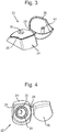
- Closure 22 sits on bottle 20 ( Figs. 5 and 6 ).
- Closure 22 includes closure base 24 connected to closing cover 26 by hinge 28, although other possible arrangements will be apparent to one of ordinary skill in the art.
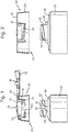
- Closure base 24 includes generally cylindrical snap-on pipe 30, best seen in Figs. 1 and 2 , depending downwardly from upper wall 25. Cylindrical snap-on pipe 30 is positioned to engage neck 32 of bottle 20. The inner wall of cylindrical snap-on pipe 30 includes one or more internal threads 34, which protrude inwardly.
- Closure base 24 includes a dispensing opening 36 centrally disposed within upper wall 25. Although opening 36 is illustrated and described as being centrally disposed, it may be off-center if desired. Structure may be provided above and/or below opening 36 to assist with pouring or sealing, such as ring 38. When closure base 24 is positioned on bottle 20, opening 36 is in communication with the interior of bottle 20 through the interior of snap-on pipe 30 and exterior closure base wall 23. Closing cover 26 includes plug 40 to assist in sealing the bottle.
- Neck 32 of bottle 20 includes external threaded protrusion 60.
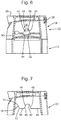
- cylindrical snap-on pipe 30 includes resistance recess 42 extending upwardly from bottom end or rim 43. Rim 43 typically extends perpendicularly to the downwardly extending axis of the pipe. A second resistance recess 42a may be present 180° removed from resistance recess 42, as seen in Fig. 1 .
- Resistance recess 42 includes two walls 44, 46 formed in cylindrical snap-on pipe 30. The shape of walls 44, 46 will depend upon the direction which it is desired to have the closure rotate in order to release it from the bottle so that it can be removed.
- closures are unscrewed/opened/removed by turning counterclockwise, so for the purpose of the present description counterclockwise unscrewing/opening will be assumed.
- counterclockwise unscrewing/opening will be assumed.
- a different direction could be used if desired and the shapes of walls 44, 46 and the location of guidance recess 70 will be adjusted accordingly.
- resistance recess 42 receives at least part of forcing element 50, which is a protrusion permanently associated with bottle shoulder 80.
- the trailing resistance recess wall during unscrewing/opening rotation illustrated as 44 in Fig. 7 , includes at its lower end 45 a gradient which is more gradual than that of the opposite (leading) recess wall 46; the gradient at the lower end of resistance recess wall 46 is more severe or steep.
- the forcing element 50 also includes two side walls 54, 52 of different gradients.
- the smaller, gentler gradient at 45 ( Fig. 7 ) of the resistance recess wall 44 is similar or identical to the gradient of side wall 54 of the forcing element of the container, which faces resistance recess wall 44 during unscrewing/opening.
- the gradient of wall of 44 at section 45 is within the range of between 10 degrees more and 10 degrees less than that of wall 54. Thus, if wall 54 is 45 degrees, wall 44 at section 45 is within the range of from 35 degrees to 55 degrees. Each of wall 44 and 54 is within the range of between 30 and 85 degrees.
- the gradient of wall 44 at section 45 is measured relative to a horizontal line drawn through rim section 56.
- the gradient of wall 54 is measured at the point at which it first contacts wall 44 upon rotation and is measured with respect to a horizontal line intersecting the point of contact with wall 44, the line being parallel to, or coincident with, bottom rim section 56.
- Guidance recess 70 includes an upwardly extending wall 72 at a gradient within the range of 90 and 135 degrees to a horizontal line drawn through section 56 of the bottom rim and then a downwardly extending wall 74 at a less severe gradient of within the range of 0 to10 degrees relative to a horizontal line drawn through the intersection 75 of wall 74 and pipe bottom 43.
- the distance between resistance recess 42 and the guidance recess 70 is measured along bottom rim section 56 from the point at which wall 44 merges with snap on pipe bottom end or rim 43 to the point at which guidance recess wall 70 begins to ascend at the beginning of wall 72.
- the distance between the resistance recess and the guidance recess in the unscrewing/opening direction is preferably at least 3mm.
- the distance is typically from 2mm up to 5mm, especially from 2mm to 4mm.
- the presence of the guidance recess in addition to the resistance recess also facilitates rotation of the closure in the opposite, closing, direction, which is generally clockwise.
- closing direction When the closure is rotated in the clockwise, closing direction, at point 75 ( Fig. 5 ), forcing element 50 encounters gradually upwardly sloping wall 74 of guidance recess 70, then the steeper, downward slope of wall 72, then rim 43 at section 56 and finally resistance recess wall 44 and steep wall 46.
- closure 22 is snap fit onto neck 32 (e.g., Fig. 2 ) of bottle 20 by closure 22 being pressed axially downwardly (or bottle 20 being pressed axially upwardly, or both). Since the bottle body and the closure are made of a flexible material and/or because the presence of one or more recesses in the pipe permits the cylindrical snap-on pipe 30 to expand resiliently radially, the internal thread 34 on the cylindrical snap-on pipe passes over the external thread 60 on the container neck and the closure snaps onto the neck. Thus, the closure is securely attached to the container and a substantial amount of effort would be needed for the consumer or other external force to separate them using a vertical or upward motion. Alternatively, closure 22 may initially be applied onto container 20 by being rotated on, to engage the threads.
- the product is dispensed with cover 26 removed from opening 36. Cover 26 is then closed so that plug 40 seals the opening when the product is not in use.
- the consumer When the bottle is substantially empty of the shampoo, body wash, lotion or other product originally contained within, the consumer removes closure 22 from the package to facilitate refilling and reusing it.
- the consumer rotates it, typically in the counterclockwise direction, starting from the position shown in Fig. 6 .
- cylindrical snap-on pipe thread 34 is forced past container neck thread 60. Thread 34 is able to pass container neck thread 60 since the cylindrical snap-on pipe is able to expand radially due to the presence of the recesses and/or due to the flexible nature of the material of which the cylindrical snap-on pipe is fabricated.
- Forcing element 50 next encounters section 56 of bottom rim 43 of the cylindrical snap-on pipe and then upwardly extending wall 72 of guidance recess 70.
- the latter permits the cylindrical snap-on pipe axially to lower itself toward the container neck, which in turn permits cylindrical snap-on pipe thread 34 to lie on thread 60 whereupon the consumer can continue to use a normal rotation to unscrew the closure from the container neck.
- Fig. 5 shows forcing element 50 within recess 70. This unscrewing rotation is further facilitated by forcing element top 58 contacting downwardly extending wall 74 of guidance recess 70. Contact by the top 58 with downwardly extending wall 74 raises the closure cylindrical snap-on pipe to support the normal unscrewing action of the closure, whereby the closure is easily removed.
- the pitch of the threads is similar to the gradient of wall 74.
- the consumer With the closure removed, the consumer then refills the bottle with the shampoo or other product. She then applies the closure back onto the bottle either by snapping the closure downwardly over the bottle neck in an axial direction similar to that used in manufacture, or she screws the closure back on to the bottle neck. If she chooses the latter, the clockwise-moving rim 43 of pipe 30 contacts top 58 of forcing element 50. When it reaches point 75 ( Fig. 5 ), it encounters gradually ascending wall 74 which contact results in a lowering of the pipe relative to the bottle neck consistent with the normal screwing downwardly of a closure.
- Closure 22 may be also be applied onto the container during manufacture by being rotated to engage the threads.
- the closure may be made from polypropylene and the bottle can be molded from high-density polyethylene or polypropylene.
- the closure is designed to be durable, resisting normal wear and tear by opening and closing the closure and even by dropping.
Claims (12)
- Fermeture (22) comprenant :a. une paroi supérieure (25) définissant une ouverture (36) ;b. un tuyau encliquetable cylindrique (30) s'étendant à partir de la paroi supérieure (25) et s'étendant de manière axiale jusqu'à une extrémité inférieure (43),c. le tuyau encliquetable cylindrique (30) comprenant au moins un évidement de résistance (42) au niveau de son extrémité inférieure (43) ;d. le tuyau encliquetable cylindrique (30) comprenant en outre au moins un filetage (34) sur sa paroi interne ;e. le tuyau encliquetable cylindrique (30) définissant des première (46) et seconde (44) parois opposées de l'évidement de résistance (42) ;f. les première (46) et seconde (44) parois d'évidement de résistance ayant des gradients, dans laquelle le gradient de l'une des première (46) et seconde (44) parois d'évidement de résistance étant inférieur au moins au niveau d'un point, au gradient sur l'autre des première et seconde parois d'évidement de résistance (46, 44) au niveau d'un point se trouvant à la même hauteur axiale, la paroi d'évidement de résistance (46) avec le gradient supérieur pour être en contact un élément de forçage (50) d'un récipient (20), et pour résister à la rotation de la fermeture (22) dans une direction de fermeture et la paroi d'évidement de résistance (44) opposée ayant un gradient plus doux de sorte que lorsque la fermeture (22) est pivotée dans la direction d'ouverture opposée, le contact entre le gradient plus doux de la seconde paroi d'évidement de résistance (44) et l'élément de forçage (50) peut forcer la fermeture (22) axialement vers le haut par rapport à un goulot de récipient (32) ; caractérisée en ce que :
g. l'extrémité inférieure (43) du tuyau encliquetable cylindrique (30) comprend un évidement de guidage (70) pour abaisser le filetage (34) du tuyau encliquetable cylindrique par rapport au goulot de récipient (32), l'évidement de guidage (70) comprend, dans la direction d'ouverture de fermeture, une première paroi d'évidement de guidage (72) avec un gradient ascendant et une seconde paroi d'évidement de guidage (74) ayant un gradient descendant afin de, dans la direction de rotation, dévisser la fermeture (22) après le contact de la première paroi d'évidement de guidage (72) avec un élément de forçage (50) sur le récipient (20), le tuyau encliquetable cylindrique (30) peut être abaissé par rapport au récipient (20) et lors du contact de la seconde paroi d'évidement de guidage (74) avec l'élément de forçage (50), le tuyau encliquetable cylindrique (30) est levé par rapport au récipient (20), et dans laquelle lorsque la fermeture (22) est pivotée dans la direction de fermeture, l'élément de forçage (50) rencontre la seconde paroi d'évidement de guidage (74) s'étendant vers le haut qui permet au tuyau encliquetable cylindrique (30) de s'abaisser lui-même axialement vers le goulot de récipient (32) et lorsque la paroi latérale (52) et/ou la partie supérieure (58) de l'élément de forçage (50) rencontre la première paroi d'évidement de guidage (72), le tuyau encliquetable (30) est levé par rapport au goulot de récipient (32) et ensuite la partie supérieure (58) de l'élément de forçage (50) peut être en contact avec une section (56) de l'extrémité inférieure (43) du tuyau encliquetable (30) et après une rotation supplémentaire, l'élément de forçage (50) atteint la seconde paroi d'évidement de résistance (44) et le tuyau encliquetable (30) peut se déplacer vers le bas lorsque l'élément de forçage (50) est logé à l'intérieur de l'évidement de résistance (42), et lorsque l'élément de forçage (50) rencontre la première paroi d'évidement de résistance (46) pentue, la fermeture (22) ne peut pas tourner davantage. - Fermeture selon la revendication 1, comprenant en outre un couvercle de fermeture (26) pour fermer l'ouverture (36), le couvercle de fermeture étant fixé, par charnière, à une base de fermeture (24) de la fermeture.
- Fermeture selon la revendication 1, dans laquelle suite au contact de l'élément de forçage (50) avec la première paroi d'évidement de guidage (72), le filetage (34) du tube encliquetable cylindrique et un filetage (60) de goulot de récipient peuvent se mettre en prise.
- Fermeture selon la revendication 1, dans laquelle la seconde paroi d'évidement de résistance (44) comprend le plus petit gradient et le plus petit gradient de la seconde paroi d'évidement de résistance (44) est de 10 degrés de moins jusqu'à 10 degrés de plus qu'un gradient d'une paroi latérale (54) de l'élément de forçage (50) du récipient (20) qui fait face à la seconde paroi d'évidement de résistance (44) pendant le dévissage de la fermeture, et le plus petit gradient de la seconde paroi d'évidement de résistance (44) et de la paroi latérale (54) de l'élément de forçage (50) faisant face à ladite seconde paroi d'évidement de résistance (44) ayant des gradients compris entre 30 et 85 degrés.
- Récipient comprenant une fermeture (22) et une bouteille (20) combinées, qui comprend la fermeture selon la revendication 1, et une bouteille ayant un goulot de bouteille (32) et au moins un élément de forçage (50), le goulot de bouteille ayant des filetages externes (60),
le au moins un élément de forçage de bouteille étant adapté pour être au moins partiellement reçu à l'intérieur de l'évidement de résistance (42) du tuyau encliquetable cylindrique (30) de fermeture. - Récipient selon la revendication 5, dans lequel suite au contact de l'élément de forçage (50) avec la première paroi d'évidement de guidage (70), le filetage de tuyau encliquetable cylindrique (34) et le filetage de goulot de bouteille (60) se mettent en prise.
- Fermeture (22) selon la revendication 1, dans laquelle la distance entre l'évidement de résistance (42) et l'évidement de guidage (70) dans la direction de dévissage est d'au moins 2 mm.
- Fermeture selon la revendication 7, dans laquelle la distance entre l'évidement de résistance et l'évidement de guidage dans la direction de dévissage est de 2 mm jusqu'à 5 mm.
- Fermeture selon la revendication 8, dans laquelle la distance entre l'évidement de résistance et l'évidement de guidage dans la direction de dévissage est de 2 mm jusqu'à 4 mm.
- Fermeture selon la revendication 1, dans laquelle une première paroi d'évidement de guidage (72) a un gradient allant de 90 à 135 degrés.
- Fermeture (22) selon la revendication 1, dans laquelle la seconde paroi d'évidement de guidage (74) a un gradient allant de 0 à 10 degrés.
- Récipient selon la revendication 5, dans lequel :
la seconde paroi d'évidement de résistance (44) comprend le gradient inférieur et le gradient inférieur de la seconde paroi d'évidement de résistance (44) est de 10 degrés de moins juqu'à 10 degrés de plus qu'un gradient de la paroi latérale (54) de l'élément de forçage (50) du récipient qui fait face à la seconde paroi d'évidement de résistance (44) pendant le dévissage de la fermeture, et le gradient inférieur de la seconde paroi d'évidement de résistance (44) et de la paroi latérale de l'élément de forçage (50) faisant face à ladite seconde paroi d'évidement de résistance (44) ayant des gradients compris entre 30 et 85 degrés.
Applications Claiming Priority (2)
| Application Number | Priority Date | Filing Date | Title |
|---|---|---|---|
| EP15202602 | 2015-12-23 | ||
| PCT/EP2016/081755 WO2017108697A1 (fr) | 2015-12-23 | 2016-12-19 | Bouchon |
Publications (2)
| Publication Number | Publication Date |
|---|---|
| EP3393923A1 EP3393923A1 (fr) | 2018-10-31 |
| EP3393923B1 true EP3393923B1 (fr) | 2019-10-23 |
Family
ID=55022393
Family Applications (2)
| Application Number | Title | Priority Date | Filing Date |
|---|---|---|---|
| EP16816676.7A Active EP3393923B1 (fr) | 2015-12-23 | 2016-12-19 | Fermeture |
| EP18728145.6A Pending EP3630637A1 (fr) | 2015-12-23 | 2018-05-30 | Bouchon |
Family Applications After (1)
| Application Number | Title | Priority Date | Filing Date |
|---|---|---|---|
| EP18728145.6A Pending EP3630637A1 (fr) | 2015-12-23 | 2018-05-30 | Bouchon |
Country Status (12)
| Country | Link |
|---|---|
| US (5) | US11312543B2 (fr) |
| EP (2) | EP3393923B1 (fr) |
| JP (3) | JP6891175B2 (fr) |
| CN (3) | CN108473237B (fr) |
| AR (1) | AR107185A1 (fr) |
| BR (2) | BR112018010908B1 (fr) |
| CA (2) | CA3007440C (fr) |
| EA (2) | EA034505B1 (fr) |
| MX (2) | MX2018007539A (fr) |
| PH (2) | PH12018501194A1 (fr) |
| WO (2) | WO2017108697A1 (fr) |
| ZA (2) | ZA201803490B (fr) |
Families Citing this family (13)
| Publication number | Priority date | Publication date | Assignee | Title |
|---|---|---|---|---|
| US10507957B2 (en) * | 2014-09-18 | 2019-12-17 | Colgate-Palmolive Company | Flip-top cap |
| US11312543B2 (en) | 2015-12-23 | 2022-04-26 | Conopco, Inc. | Closure |
| US10543962B2 (en) | 2017-06-23 | 2020-01-28 | Elc Management Llc | Container and cap assembly |
| US10077142B1 (en) | 2017-06-23 | 2018-09-18 | Elc Management Llc | Containers with pull-off, snap-fit caps |
| US10829274B2 (en) * | 2018-11-15 | 2020-11-10 | Closure Systems International Inc. | Flip-top closure |
| FR3096968B1 (fr) * | 2019-06-07 | 2021-07-23 | Albea Services | Ensemble pour la fermeture d’un tube et tube comprenant cet ensemble |
| FR3096966B1 (fr) * | 2019-06-07 | 2021-06-25 | Albea Services | Ensemble pour la fermeture d’un tube et tube comprenant cet ensemble |
| WO2021099964A1 (fr) * | 2019-11-18 | 2021-05-27 | Johnson & Johnson Consumer Inc. | Fermeture à couvercle rabattable |
| FR3108101B1 (fr) * | 2020-03-16 | 2022-07-15 | Oreal | Dispositif de conditionnement comportant une capsule de fermeture pré-positionnable sur un col de récipient |
| WO2021224156A1 (fr) * | 2020-05-04 | 2021-11-11 | Emsa Gmbh | Fermeture de bouteille pour boire dotée d'un bouchon de fermeture rotatif pour une bouteille isotherme ou pour une tasse isotherme |
| WO2022028832A1 (fr) | 2020-08-03 | 2022-02-10 | Unilever Ip Holdings B.V. | Adaptateur |
| BR112023001196A2 (pt) * | 2020-08-03 | 2023-02-14 | Unilever Ip Holdings B V | Fecho e recipiente |
| FR3137074A1 (fr) * | 2022-06-24 | 2023-12-29 | L'oreal | Ensemble de conditionnement et de distribution de produit, notamment cosmétique, comprenant un organe de distribution |
Family Cites Families (67)
| Publication number | Priority date | Publication date | Assignee | Title |
|---|---|---|---|---|
| GB739485A (en) | 1952-06-16 | 1955-11-02 | Hugh Alfred Jones | Improvements in and relating to filters |
| US2773521A (en) | 1954-03-02 | 1956-12-11 | Persson Nels Leonard | Coupling for squeeze bottles |
| US3156272A (en) | 1962-01-22 | 1964-11-10 | William G Indrunas | Bottle coupling device |
| US3945617A (en) | 1974-01-14 | 1976-03-23 | Callery Thomas R | Mixing method and means |
| JPS5742846Y2 (fr) * | 1979-11-19 | 1982-09-21 | ||
| JPS5681049A (en) | 1979-12-05 | 1981-07-02 | Fujitsu Denso | Laod control system utilizing readily installed indoor commercial wire |
| US4347879A (en) | 1981-03-27 | 1982-09-07 | Blaser Anton J | Bottle neck coupling device |
| US4456137A (en) | 1982-07-19 | 1984-06-26 | Data Packaging Corporation | Venting arrangement for covered containers |
| JPS5943348A (ja) | 1982-09-03 | 1984-03-10 | Hitachi Ltd | 空燃比センサ |
| JPS5943348U (ja) * | 1982-09-14 | 1984-03-22 | 紀伊産業株式会社 | キヤツプ付き容器 |
| FR2571696B1 (fr) | 1984-10-11 | 1987-02-20 | Oreal | Dispositif de bouchage a position de fermeture indexee pour flacon en verre ou autre matiere rigide et flacon destine a etre equipe d'un tel dispositif |
| DE8702986U1 (fr) | 1987-02-26 | 1987-04-09 | Aerosol Inventions And Development S.A. A.I.D. S.A., Freiburg/Fribourg, Ch | |
| US4991733A (en) * | 1989-09-25 | 1991-02-12 | West Penn Plastic, Inc. | Closure and container having pass over inter-engaging ratchet teeth |
| US5145080A (en) | 1991-04-26 | 1992-09-08 | Seaquist Closures | Positive orientation system for a threaded closure and container |
| DE4212434A1 (de) | 1992-04-14 | 1993-10-21 | Henkel Kgaa | Anordnung zum Nachfüllen eines Behälters |
| CA2098544A1 (fr) | 1993-06-16 | 1994-12-17 | J. Frederick Hodgson | Connecteur pour contenants d'aliments ou de boissons |
| DE19602258A1 (de) | 1996-01-23 | 1997-07-24 | Cebal Verpackungen | Kunststofftube mit einem Tubenkörper, sowie Verfahren zu deren Herstellung |
| US5690242A (en) * | 1996-03-25 | 1997-11-25 | Winfield Industries | Sharps disposal container cap securement arrangement |
| US5725132A (en) | 1996-09-25 | 1998-03-10 | Contico International, Inc. | Dispenser with snap-fit container connection |
| US5884678A (en) | 1996-12-27 | 1999-03-23 | Chudy; Dennis J. | Connector device for holding two necks in an abutting relationship |
| CZ291703B6 (cs) | 1997-08-27 | 2003-05-14 | Pentapharm Ag | Dvojný systém spojení lékovek pro lyofilizované produkty |
| GB2342347A (en) | 1998-10-02 | 2000-04-12 | Unilever Plc | Closure for refill container |
| US6155462A (en) | 1999-05-04 | 2000-12-05 | Owens-Illinois Closure Inc. | Bayonet-type finish for a container |
| FR2810639B1 (fr) | 2000-06-21 | 2002-09-06 | Oreal | Ensemble pour le melange extemporane de deux produits |
| DE10207204A1 (de) * | 2001-04-05 | 2002-12-12 | Alpla Werke | Kombination aus einer Flasche mit rastgehaltertem Adapter und/oder einer Verschlusskappe |
| US6659145B1 (en) | 2002-01-22 | 2003-12-09 | Michael Y. Reif | Toothpaste tube filling or replenishment unit |
| JP2004136976A (ja) * | 2002-09-24 | 2004-05-13 | Uchida Yoki Kk | ねじ式蓋構造並びにこれを用いたねじ式蓋部及びその製造方法 |
| DE20308059U1 (de) | 2003-05-21 | 2003-08-14 | Klein Walter | System zur Wiederbfüllung und/oder Auffüllung eines Behältnisses bzw. Adapter für das zuvor genannte System |
| US20040265156A1 (en) | 2003-05-29 | 2004-12-30 | David Byron | Pressure-limiting pump system for pressurizing a vessel |
| US7128227B2 (en) | 2003-09-22 | 2006-10-31 | Polytop Corporation | Dispensing closure with stop wall for positive alignment on container |
| JP2005200026A (ja) | 2004-01-13 | 2005-07-28 | Ebisuya Kagaku Kogyo Kk | 蓋構造 |
| FR2867761A1 (fr) | 2004-03-19 | 2005-09-23 | Mt Packaging | Recharche pour distributeur de produit cosmetique |
| CN2734649Y (zh) | 2004-09-28 | 2005-10-19 | 何益秋 | 一种方便开启瓶盖 |
| KR20060059750A (ko) * | 2004-11-29 | 2006-06-02 | 안진희 | 스트로를 구비한 용기마개 |
| US7735665B2 (en) * | 2005-02-18 | 2010-06-15 | Rexam Closure Systems Inc. | Child-resistant flip-top dispensing closure, package and method of manufacture |
| US7510095B2 (en) | 2005-03-11 | 2009-03-31 | Berry Plastics Corporation | System comprising a radially aligned container and closure |
| USD542141S1 (en) | 2005-07-26 | 2007-05-08 | Conopco, Inc. | Combined bottle and cap |
| USD546693S1 (en) | 2005-07-26 | 2007-07-17 | Conopco, Inc. | Combined bottle and cap |
| ATE522279T1 (de) | 2006-06-02 | 2011-09-15 | Idispense Llc | Kindersichere konzentratpatrone und zugehöriger verdünnungs- und abgabebehälter |
| US7621413B2 (en) | 2006-06-09 | 2009-11-24 | Seaquist Closures Foreign, Inc. | Closure system with orientation and removal capability |
| US7607460B2 (en) | 2006-06-12 | 2009-10-27 | Jpro Dairy International, Inc. | Coupling assembly |
| US8365933B2 (en) * | 2007-07-13 | 2013-02-05 | Aptar Freyung Gmbh | Closure system for a container and dispensing closure |
| FR2925033B1 (fr) | 2007-12-12 | 2012-10-05 | Valois Sas | Distributeur de produit fluide. |
| US8267274B2 (en) * | 2008-03-27 | 2012-09-18 | Aptargroup, Inc. | Closure having a drip minimizing lid |
| CN201400373Y (zh) | 2009-03-20 | 2010-02-10 | 郑宗谟 | 具有记录功能的瓶盖 |
| KR20110067284A (ko) | 2009-12-14 | 2011-06-22 | 서인철 | 치약 주입용 니플 |
| JP5588673B2 (ja) * | 2009-12-29 | 2014-09-10 | 日本山村硝子株式会社 | 容器 |
| FR2957903B1 (fr) | 2010-03-25 | 2014-01-24 | Valois Sas | Distributeur de produit fluide. |
| DE102011008060B3 (de) | 2011-01-07 | 2012-07-19 | Henkel Ag & Co. Kgaa | Verschlussvorrichtung für einen Behälter |
| JP5681049B2 (ja) | 2011-06-27 | 2015-03-04 | 株式会社アイ・ライティング・システム | Led電源回路 |
| US8673242B2 (en) | 2011-09-06 | 2014-03-18 | National Scientific Company | Over-torque resistant vial |
| US20130146174A1 (en) | 2011-12-12 | 2013-06-13 | Parker Laboratories, Inc. | Adaptor for connecting a fluid package to a dispenser bottle |
| KR101212771B1 (ko) | 2012-04-13 | 2012-12-20 | 이은진 | 리필 어댑터가 내장된 여행용 치약의 마개 |
| US20140069552A1 (en) | 2012-10-24 | 2014-03-13 | Shenzhen China Star Optoelectronics Technology Co. Ltd. | Docking device for material bottles |
| US20140251938A1 (en) | 2013-03-08 | 2014-09-11 | Steve Rose | Bottle cap system with internal storage chamber |
| US20140291277A1 (en) | 2013-03-27 | 2014-10-02 | Diane Perez | Bottle transfer device |
| US9227825B2 (en) | 2013-05-22 | 2016-01-05 | Daniel Wulstein | Bottle coupling device |
| CN203318920U (zh) * | 2013-06-14 | 2013-12-04 | 威玛精密化学科技股份有限公司 | 容器 |
| US9850040B2 (en) | 2014-03-21 | 2017-12-26 | Emd Millipore Corporation | Container and container engaging member suitable for vacuum assisted filtration |
| US10507957B2 (en) | 2014-09-18 | 2019-12-17 | Colgate-Palmolive Company | Flip-top cap |
| US11312543B2 (en) | 2015-12-23 | 2022-04-26 | Conopco, Inc. | Closure |
| JP6788884B2 (ja) * | 2016-08-24 | 2020-11-25 | 三笠産業株式会社 | キャップ |
| US10029903B1 (en) | 2016-09-06 | 2018-07-24 | Karen F. White | Bottle transfer coupling device |
| EP3526130A1 (fr) | 2016-10-14 | 2019-08-21 | Colgate-Palmolive Company | Récipient |
| EP3936457A1 (fr) | 2016-12-22 | 2022-01-12 | Unilever IP Holdings B.V. | Un accessoire à combiner avec une fermeture |
| US20180237286A1 (en) | 2017-02-23 | 2018-08-23 | Michael Seiba | Toothpaste transfer device and method |
| FR3084655B1 (fr) | 2018-08-01 | 2020-11-13 | Albea Services | Montage et demontage facilite d'une pompe par rapport au reservoir |
-
2016
- 2016-12-19 US US16/065,173 patent/US11312543B2/en active Active
- 2016-12-19 WO PCT/EP2016/081755 patent/WO2017108697A1/fr active Application Filing
- 2016-12-19 BR BR112018010908-8A patent/BR112018010908B1/pt active IP Right Grant
- 2016-12-19 JP JP2018530514A patent/JP6891175B2/ja active Active
- 2016-12-19 CN CN201680074880.4A patent/CN108473237B/zh active Active
- 2016-12-19 CA CA3007440A patent/CA3007440C/fr active Active
- 2016-12-19 MX MX2018007539A patent/MX2018007539A/es unknown
- 2016-12-19 EP EP16816676.7A patent/EP3393923B1/fr active Active
- 2016-12-19 EA EA201891037A patent/EA034505B1/ru not_active IP Right Cessation
- 2016-12-23 AR ARP160104008A patent/AR107185A1/es active IP Right Grant
-
2017
- 2017-06-01 US US15/611,781 patent/US10730669B2/en active Active
-
2018
- 2018-05-25 ZA ZA2018/03490A patent/ZA201803490B/en unknown
- 2018-05-30 BR BR112019023858-1A patent/BR112019023858B1/pt active IP Right Grant
- 2018-05-30 CA CA3064951A patent/CA3064951A1/fr active Pending
- 2018-05-30 JP JP2019563397A patent/JP7463106B2/ja active Active
- 2018-05-30 MX MX2019014194A patent/MX2019014194A/es unknown
- 2018-05-30 CN CN201880035831.9A patent/CN110709331B/zh active Active
- 2018-05-30 CN CN202110101378.0A patent/CN112744445A/zh active Pending
- 2018-05-30 EP EP18728145.6A patent/EP3630637A1/fr active Pending
- 2018-05-30 WO PCT/EP2018/064188 patent/WO2018220013A1/fr active Application Filing
- 2018-05-30 EA EA201992403A patent/EA038679B1/ru unknown
- 2018-06-06 PH PH12018501194A patent/PH12018501194A1/en unknown
-
2019
- 2019-11-07 PH PH12019502497A patent/PH12019502497A1/en unknown
- 2019-11-14 ZA ZA2019/07551A patent/ZA201907551B/en unknown
-
2020
- 2020-08-03 US US16/983,376 patent/US11702251B2/en active Active
-
2022
- 2022-04-21 US US17/726,393 patent/US11794956B2/en active Active
-
2023
- 2023-06-07 US US18/206,832 patent/US20230312184A1/en active Pending
- 2023-12-20 JP JP2023214998A patent/JP2024026434A/ja active Pending
Non-Patent Citations (1)
| Title |
|---|
| None * |
Also Published As
Similar Documents
| Publication | Publication Date | Title |
|---|---|---|
| US11794956B2 (en) | Closure | |
| US8292101B1 (en) | Flip-top dispensing system with a child resistant latch mechanism | |
| US20060186078A1 (en) | Screw on dispensing closure with structure for preventing removal | |
| US20080023502A1 (en) | Closure Cap | |
| RU2516177C2 (ru) | Бутылка с защитным колпачком | |
| JP6243354B2 (ja) | リフィル容器用注出構造 | |
| EP4188821B1 (fr) | Bouchon de contenant se fixant par encliquetage et s'enlevant par torsion | |
| EP4100095A1 (fr) | Col fileté pour une bouteille | |
| JP2023536303A (ja) | アダプタ | |
| AU4734000A (en) | Bottle closure |
Legal Events
| Date | Code | Title | Description |
|---|---|---|---|
| STAA | Information on the status of an ep patent application or granted ep patent |
Free format text: STATUS: UNKNOWN |
|
| STAA | Information on the status of an ep patent application or granted ep patent |
Free format text: STATUS: THE INTERNATIONAL PUBLICATION HAS BEEN MADE |
|
| PUAI | Public reference made under article 153(3) epc to a published international application that has entered the european phase |
Free format text: ORIGINAL CODE: 0009012 |
|
| STAA | Information on the status of an ep patent application or granted ep patent |
Free format text: STATUS: REQUEST FOR EXAMINATION WAS MADE |
|
| 17P | Request for examination filed |
Effective date: 20180529 |
|
| AK | Designated contracting states |
Kind code of ref document: A1 Designated state(s): AL AT BE BG CH CY CZ DE DK EE ES FI FR GB GR HR HU IE IS IT LI LT LU LV MC MK MT NL NO PL PT RO RS SE SI SK SM TR |
|
| AX | Request for extension of the european patent |
Extension state: BA ME |
|
| GRAP | Despatch of communication of intention to grant a patent |
Free format text: ORIGINAL CODE: EPIDOSNIGR1 |
|
| STAA | Information on the status of an ep patent application or granted ep patent |
Free format text: STATUS: GRANT OF PATENT IS INTENDED |
|
| DAV | Request for validation of the european patent (deleted) | ||
| DAX | Request for extension of the european patent (deleted) | ||
| INTG | Intention to grant announced |
Effective date: 20190328 |
|
| GRAJ | Information related to disapproval of communication of intention to grant by the applicant or resumption of examination proceedings by the epo deleted |
Free format text: ORIGINAL CODE: EPIDOSDIGR1 |
|
| STAA | Information on the status of an ep patent application or granted ep patent |
Free format text: STATUS: REQUEST FOR EXAMINATION WAS MADE |
|
| GRAP | Despatch of communication of intention to grant a patent |
Free format text: ORIGINAL CODE: EPIDOSNIGR1 |
|
| STAA | Information on the status of an ep patent application or granted ep patent |
Free format text: STATUS: GRANT OF PATENT IS INTENDED |
|
| INTC | Intention to grant announced (deleted) | ||
| INTG | Intention to grant announced |
Effective date: 20190621 |
|
| GRAS | Grant fee paid |
Free format text: ORIGINAL CODE: EPIDOSNIGR3 |
|
| GRAA | (expected) grant |
Free format text: ORIGINAL CODE: 0009210 |
|
| STAA | Information on the status of an ep patent application or granted ep patent |
Free format text: STATUS: THE PATENT HAS BEEN GRANTED |
|
| AK | Designated contracting states |
Kind code of ref document: B1 Designated state(s): AL AT BE BG CH CY CZ DE DK EE ES FI FR GB GR HR HU IE IS IT LI LT LU LV MC MK MT NL NO PL PT RO RS SE SI SK SM TR |
|
| REG | Reference to a national code |
Ref country code: GB Ref legal event code: FG4D |
|
| REG | Reference to a national code |
Ref country code: CH Ref legal event code: EP |
|
| REG | Reference to a national code |
Ref country code: IE Ref legal event code: FG4D |
|
| REG | Reference to a national code |
Ref country code: AT Ref legal event code: REF Ref document number: 1193402 Country of ref document: AT Kind code of ref document: T Effective date: 20191115 |
|
| REG | Reference to a national code |
Ref country code: DE Ref legal event code: R096 Ref document number: 602016023091 Country of ref document: DE |
|
| REG | Reference to a national code |
Ref country code: NL Ref legal event code: MP Effective date: 20191023 |
|
| REG | Reference to a national code |
Ref country code: LT Ref legal event code: MG4D |
|
| PG25 | Lapsed in a contracting state [announced via postgrant information from national office to epo] |
Ref country code: SE Free format text: LAPSE BECAUSE OF FAILURE TO SUBMIT A TRANSLATION OF THE DESCRIPTION OR TO PAY THE FEE WITHIN THE PRESCRIBED TIME-LIMIT Effective date: 20191023 Ref country code: LV Free format text: LAPSE BECAUSE OF FAILURE TO SUBMIT A TRANSLATION OF THE DESCRIPTION OR TO PAY THE FEE WITHIN THE PRESCRIBED TIME-LIMIT Effective date: 20191023 Ref country code: NO Free format text: LAPSE BECAUSE OF FAILURE TO SUBMIT A TRANSLATION OF THE DESCRIPTION OR TO PAY THE FEE WITHIN THE PRESCRIBED TIME-LIMIT Effective date: 20200123 Ref country code: FI Free format text: LAPSE BECAUSE OF FAILURE TO SUBMIT A TRANSLATION OF THE DESCRIPTION OR TO PAY THE FEE WITHIN THE PRESCRIBED TIME-LIMIT Effective date: 20191023 Ref country code: BG Free format text: LAPSE BECAUSE OF FAILURE TO SUBMIT A TRANSLATION OF THE DESCRIPTION OR TO PAY THE FEE WITHIN THE PRESCRIBED TIME-LIMIT Effective date: 20200123 Ref country code: GR Free format text: LAPSE BECAUSE OF FAILURE TO SUBMIT A TRANSLATION OF THE DESCRIPTION OR TO PAY THE FEE WITHIN THE PRESCRIBED TIME-LIMIT Effective date: 20200124 Ref country code: NL Free format text: LAPSE BECAUSE OF FAILURE TO SUBMIT A TRANSLATION OF THE DESCRIPTION OR TO PAY THE FEE WITHIN THE PRESCRIBED TIME-LIMIT Effective date: 20191023 Ref country code: PL Free format text: LAPSE BECAUSE OF FAILURE TO SUBMIT A TRANSLATION OF THE DESCRIPTION OR TO PAY THE FEE WITHIN THE PRESCRIBED TIME-LIMIT Effective date: 20191023 Ref country code: LT Free format text: LAPSE BECAUSE OF FAILURE TO SUBMIT A TRANSLATION OF THE DESCRIPTION OR TO PAY THE FEE WITHIN THE PRESCRIBED TIME-LIMIT Effective date: 20191023 Ref country code: PT Free format text: LAPSE BECAUSE OF FAILURE TO SUBMIT A TRANSLATION OF THE DESCRIPTION OR TO PAY THE FEE WITHIN THE PRESCRIBED TIME-LIMIT Effective date: 20200224 |
|
| PG25 | Lapsed in a contracting state [announced via postgrant information from national office to epo] |
Ref country code: HR Free format text: LAPSE BECAUSE OF FAILURE TO SUBMIT A TRANSLATION OF THE DESCRIPTION OR TO PAY THE FEE WITHIN THE PRESCRIBED TIME-LIMIT Effective date: 20191023 Ref country code: RS Free format text: LAPSE BECAUSE OF FAILURE TO SUBMIT A TRANSLATION OF THE DESCRIPTION OR TO PAY THE FEE WITHIN THE PRESCRIBED TIME-LIMIT Effective date: 20191023 Ref country code: IS Free format text: LAPSE BECAUSE OF FAILURE TO SUBMIT A TRANSLATION OF THE DESCRIPTION OR TO PAY THE FEE WITHIN THE PRESCRIBED TIME-LIMIT Effective date: 20200224 |
|
| PG25 | Lapsed in a contracting state [announced via postgrant information from national office to epo] |
Ref country code: AL Free format text: LAPSE BECAUSE OF FAILURE TO SUBMIT A TRANSLATION OF THE DESCRIPTION OR TO PAY THE FEE WITHIN THE PRESCRIBED TIME-LIMIT Effective date: 20191023 |
|
| REG | Reference to a national code |
Ref country code: DE Ref legal event code: R097 Ref document number: 602016023091 Country of ref document: DE |
|
| PG2D | Information on lapse in contracting state deleted |
Ref country code: IS |
|
| PG25 | Lapsed in a contracting state [announced via postgrant information from national office to epo] |
Ref country code: IS Free format text: LAPSE BECAUSE OF FAILURE TO SUBMIT A TRANSLATION OF THE DESCRIPTION OR TO PAY THE FEE WITHIN THE PRESCRIBED TIME-LIMIT Effective date: 20200223 Ref country code: DK Free format text: LAPSE BECAUSE OF FAILURE TO SUBMIT A TRANSLATION OF THE DESCRIPTION OR TO PAY THE FEE WITHIN THE PRESCRIBED TIME-LIMIT Effective date: 20191023 Ref country code: RO Free format text: LAPSE BECAUSE OF FAILURE TO SUBMIT A TRANSLATION OF THE DESCRIPTION OR TO PAY THE FEE WITHIN THE PRESCRIBED TIME-LIMIT Effective date: 20191023 Ref country code: ES Free format text: LAPSE BECAUSE OF FAILURE TO SUBMIT A TRANSLATION OF THE DESCRIPTION OR TO PAY THE FEE WITHIN THE PRESCRIBED TIME-LIMIT Effective date: 20191023 Ref country code: CZ Free format text: LAPSE BECAUSE OF FAILURE TO SUBMIT A TRANSLATION OF THE DESCRIPTION OR TO PAY THE FEE WITHIN THE PRESCRIBED TIME-LIMIT Effective date: 20191023 Ref country code: EE Free format text: LAPSE BECAUSE OF FAILURE TO SUBMIT A TRANSLATION OF THE DESCRIPTION OR TO PAY THE FEE WITHIN THE PRESCRIBED TIME-LIMIT Effective date: 20191023 |
|
| REG | Reference to a national code |
Ref country code: CH Ref legal event code: PL |
|
| REG | Reference to a national code |
Ref country code: AT Ref legal event code: MK05 Ref document number: 1193402 Country of ref document: AT Kind code of ref document: T Effective date: 20191023 |
|
| REG | Reference to a national code |
Ref country code: BE Ref legal event code: MM Effective date: 20191231 |
|
| PLBE | No opposition filed within time limit |
Free format text: ORIGINAL CODE: 0009261 |
|
| STAA | Information on the status of an ep patent application or granted ep patent |
Free format text: STATUS: NO OPPOSITION FILED WITHIN TIME LIMIT |
|
| PG25 | Lapsed in a contracting state [announced via postgrant information from national office to epo] |
Ref country code: SM Free format text: LAPSE BECAUSE OF FAILURE TO SUBMIT A TRANSLATION OF THE DESCRIPTION OR TO PAY THE FEE WITHIN THE PRESCRIBED TIME-LIMIT Effective date: 20191023 Ref country code: IT Free format text: LAPSE BECAUSE OF FAILURE TO SUBMIT A TRANSLATION OF THE DESCRIPTION OR TO PAY THE FEE WITHIN THE PRESCRIBED TIME-LIMIT Effective date: 20191023 Ref country code: MC Free format text: LAPSE BECAUSE OF FAILURE TO SUBMIT A TRANSLATION OF THE DESCRIPTION OR TO PAY THE FEE WITHIN THE PRESCRIBED TIME-LIMIT Effective date: 20191023 Ref country code: SK Free format text: LAPSE BECAUSE OF FAILURE TO SUBMIT A TRANSLATION OF THE DESCRIPTION OR TO PAY THE FEE WITHIN THE PRESCRIBED TIME-LIMIT Effective date: 20191023 |
|
| 26N | No opposition filed |
Effective date: 20200724 |
|
| PG25 | Lapsed in a contracting state [announced via postgrant information from national office to epo] |
Ref country code: IE Free format text: LAPSE BECAUSE OF NON-PAYMENT OF DUE FEES Effective date: 20191219 Ref country code: LU Free format text: LAPSE BECAUSE OF NON-PAYMENT OF DUE FEES Effective date: 20191219 |
|
| PG25 | Lapsed in a contracting state [announced via postgrant information from national office to epo] |
Ref country code: AT Free format text: LAPSE BECAUSE OF FAILURE TO SUBMIT A TRANSLATION OF THE DESCRIPTION OR TO PAY THE FEE WITHIN THE PRESCRIBED TIME-LIMIT Effective date: 20191023 Ref country code: CH Free format text: LAPSE BECAUSE OF NON-PAYMENT OF DUE FEES Effective date: 20191231 Ref country code: LI Free format text: LAPSE BECAUSE OF NON-PAYMENT OF DUE FEES Effective date: 20191231 Ref country code: SI Free format text: LAPSE BECAUSE OF FAILURE TO SUBMIT A TRANSLATION OF THE DESCRIPTION OR TO PAY THE FEE WITHIN THE PRESCRIBED TIME-LIMIT Effective date: 20191023 Ref country code: BE Free format text: LAPSE BECAUSE OF NON-PAYMENT OF DUE FEES Effective date: 20191231 |
|
| PG25 | Lapsed in a contracting state [announced via postgrant information from national office to epo] |
Ref country code: CY Free format text: LAPSE BECAUSE OF FAILURE TO SUBMIT A TRANSLATION OF THE DESCRIPTION OR TO PAY THE FEE WITHIN THE PRESCRIBED TIME-LIMIT Effective date: 20191023 |
|
| PG25 | Lapsed in a contracting state [announced via postgrant information from national office to epo] |
Ref country code: HU Free format text: LAPSE BECAUSE OF FAILURE TO SUBMIT A TRANSLATION OF THE DESCRIPTION OR TO PAY THE FEE WITHIN THE PRESCRIBED TIME-LIMIT; INVALID AB INITIO Effective date: 20161219 Ref country code: MT Free format text: LAPSE BECAUSE OF FAILURE TO SUBMIT A TRANSLATION OF THE DESCRIPTION OR TO PAY THE FEE WITHIN THE PRESCRIBED TIME-LIMIT Effective date: 20191023 |
|
| REG | Reference to a national code |
Ref country code: DE Ref legal event code: R081 Ref document number: 602016023091 Country of ref document: DE Owner name: UNILEVER GLOBAL IP LIMITED, WIRRAL, GB Free format text: FORMER OWNER: UNILEVER NV, ROTTERDAM, NL |
|
| REG | Reference to a national code |
Ref country code: GB Ref legal event code: 732E Free format text: REGISTERED BETWEEN 20220127 AND 20220202 |
|
| PG25 | Lapsed in a contracting state [announced via postgrant information from national office to epo] |
Ref country code: TR Free format text: LAPSE BECAUSE OF FAILURE TO SUBMIT A TRANSLATION OF THE DESCRIPTION OR TO PAY THE FEE WITHIN THE PRESCRIBED TIME-LIMIT Effective date: 20191023 |
|
| PG25 | Lapsed in a contracting state [announced via postgrant information from national office to epo] |
Ref country code: MK Free format text: LAPSE BECAUSE OF FAILURE TO SUBMIT A TRANSLATION OF THE DESCRIPTION OR TO PAY THE FEE WITHIN THE PRESCRIBED TIME-LIMIT Effective date: 20191023 |
|
| P01 | Opt-out of the competence of the unified patent court (upc) registered |
Effective date: 20230502 |
|
| PGFP | Annual fee paid to national office [announced via postgrant information from national office to epo] |
Ref country code: GB Payment date: 20231220 Year of fee payment: 8 |
|
| PGFP | Annual fee paid to national office [announced via postgrant information from national office to epo] |
Ref country code: FR Payment date: 20231222 Year of fee payment: 8 Ref country code: DE Payment date: 20231214 Year of fee payment: 8 |