EP3392987B1 - Procédé et système d'assistance automatisée d'un processus de raccordement, en particulier de composants disposés dans une armoire électrique ou sur un système de montage - Google Patents
Procédé et système d'assistance automatisée d'un processus de raccordement, en particulier de composants disposés dans une armoire électrique ou sur un système de montage Download PDFInfo
- Publication number
- EP3392987B1 EP3392987B1 EP17167566.3A EP17167566A EP3392987B1 EP 3392987 B1 EP3392987 B1 EP 3392987B1 EP 17167566 A EP17167566 A EP 17167566A EP 3392987 B1 EP3392987 B1 EP 3392987B1
- Authority
- EP
- European Patent Office
- Prior art keywords
- wiring
- connection
- connecting line
- identifier
- user output
- Prior art date
- Legal status (The legal status is an assumption and is not a legal conclusion. Google has not performed a legal analysis and makes no representation as to the accuracy of the status listed.)
- Active
Links
Images


Classifications
-
- H—ELECTRICITY
- H02—GENERATION; CONVERSION OR DISTRIBUTION OF ELECTRIC POWER
- H02B—BOARDS, SUBSTATIONS OR SWITCHING ARRANGEMENTS FOR THE SUPPLY OR DISTRIBUTION OF ELECTRIC POWER
- H02B3/00—Apparatus specially adapted for the manufacture, assembly, or maintenance of boards or switchgear
-
- H—ELECTRICITY
- H02—GENERATION; CONVERSION OR DISTRIBUTION OF ELECTRIC POWER
- H02B—BOARDS, SUBSTATIONS OR SWITCHING ARRANGEMENTS FOR THE SUPPLY OR DISTRIBUTION OF ELECTRIC POWER
- H02B1/00—Frameworks, boards, panels, desks, casings; Details of substations or switching arrangements
- H02B1/015—Boards, panels, desks; Parts thereof or accessories therefor
- H02B1/04—Mounting thereon of switches or of other devices in general, the switch or device having, or being without, casing
Definitions
- the invention relates to a method with the features of the preamble of claim 1. Furthermore, the invention relates to a system with the features of the preamble of claim 5, in particular for performing the method described above. The invention also relates to the use of the system and a computer program. Such a method and system is known from US Pat WO 2016/202454 A1 known. Another method of making a wire harness is from US Pat DE 199 18 212 A1 known.
- Control cabinets are primarily used to supply systems or electrical installations with electrical energy and sometimes also with signals, for example to control a system or electrical components.
- a large number of electrical, electronic and sometimes also pneumatic or hydraulic components are typically housed in a switch cabinet.
- further electrical and electronic components can also be installed in or on a switch cabinet, which are used, for example, for air conditioning, lighting or for monitoring the switch cabinet.
- connection lines in accordance with a specified connection plan, for example a wiring plan, a tubing plan, a piping plan or a combination thereof, whereby the requirements for the individual Connection line can differ depending on the type of connection, for example because the lines must be designed for different currents, operating frequencies, cross-sections or for the transmission of data.
- Wiring diagrams are used in particular to connect electrical components; Hose and piping plans are used in particular to connect pneumatic or hydraulic components.
- a control cabinet can be fitted with the corresponding components at the factory or directly on site.
- the connection, in particular the wiring of the components can also be carried out at the factory or directly on site and is carried out manually by a technician.
- the expansion or modification of existing control cabinets also requires manual wiring, tubing or piping by a technician, in particular an electrical engineer, if factory, possibly automated wiring, tubing or piping is not possible in such cases.
- the technician performing the wiring / tubing / piping can, for example, use the information in a given circuit diagram and his know-how to determine the individual connections to be made, localize the associated connection points in the control cabinet, and use suitable connection lines for the individual connections, in particular with suitable cross-sections or from suitable materials and use them to carry out the wiring / tubing / piping.
- the technician can also proceed according to a so-called wiring, tubing and / or tubing list, in which the wiring / tubing / tubing to be carried out already exists are specified and listed.
- the technician can then work through the connections listed in the wiring, tubing and / or tubing list one after the other by using his know-how to manually locate the respective connection points of the individual wirings, determine the routing paths, and then carry out the wiring / tubing / tubing accordingly.
- connection lines required for wiring / tubing / piping There are also various methods of manufacturing the connecting lines required for wiring / tubing / piping: In this way, the technician can use his know-how to select the type of connection cable required for the individual connections himself and produce (assemble) the corresponding connection cables himself on site during the connection process. To produce the connecting lines, he can in particular cut the connecting lines to length and assemble them, for example, apply wire end treatments and / or labels.
- the connecting lines can also be automatically or manually defined and pre-assembled in advance before the technician carries out the wiring / piping / tubing.
- a so-called virtual routing can be carried out during the work preparation prior to the actual wiring / tubing / tubing, in which the wiring / tubing / tubing of the control cabinet is planned in advance, preferably with software support, so that each connecting line has a length,
- the type of connection, type of assembly and, if applicable, type of labeling is defined in advance.
- the laying routes can already be defined in advance and, if necessary, stored in a data format (such as a CAx format).
- connection line By pre-assembling the connection line and defining the laying paths in advance, the wiring / tubing / piping of a control cabinet is already significantly simplified, since the technician does not have to select the type of connection line himself, does not have to assemble the connection lines himself and preferably does not have to determine the laying paths himself.
- the present invention is based on the object of providing a method and a system with which in particular such a wiring process can be effectively supported, so that the wiring is made easier for the technician, incorrect wiring is avoided and the wiring process as a whole contributes increased quality is accelerated.
- this object is achieved by a method, characterized in that the generation of the visual user output includes the generation of a graphic representation of the connection points and the route of the connection line
- connection process or the connection of components arranged in a switch cabinet or on an assembly system is the connection of Understood connecting lines on or between the components that are arranged in a switch cabinet or on a mounting system, for example a mounting plate.
- the mounting system can be arranged in a control cabinet or be intended for such. Alternatively, it can be an independent assembly system that can also be used without a control cabinet, for example directly on a machine.
- connection process can in particular be a wiring process in which connecting lines for the wiring, such as, for example, individual wires or cables, are connected.
- connection lines for pneumatic or hydraulic components for example hoses or pipes
- connection process thus includes wiring processes, tubing processes, piping processes and also combinations thereof.
- the connection process itself is carried out manually by a technician; however, he is supported automatically by the method or system described above. In particular, the method and the system help him to unambiguously assign the pre-assembled connection lines, to identify the associated connection points and preferably also to adhere to a specified routing path by providing the technician with the information required for this purpose for the next connection line selected by him provides.
- a switch cabinet is understood to mean a device for accommodating electrotechnical, hydraulic and / or pneumatic components.
- the switch cabinet forms an enclosure to protect the components, in particular from external influences and, if necessary, from being seen. Such an enclosure also preferably enables targeted heat dissipation from the components installed in it.
- assembly systems are generally used which are known as assembly plates or assembly frames and which are built into the control cabinet. The components are mechanically fastened to these assembly systems. Furthermore, assembly systems can also be used independently of a control cabinet.
- the switch cabinet preferably has a cabinet door through which the interior of the housing is accessible so that the components can be assembled and connected.
- the components are, in particular, control technology components.
- the switch cabinet can be a switch cabinet for electrotechnical components and possibly additional hydraulic and / or pneumatic components.
- the switch cabinet can also be provided exclusively for hydraulic and / or pneumatic components.
- An assembly system is understood to mean systems that are used to install components in a control cabinet or independently of it.
- the mounting system can be, for example, a mounting frame or a mounting plate.
- a mounting plate is understood to be a plate that is used for the arrangement and mechanical fastening within a control cabinet.
- the components arranged on a mounting plate are then connected to one another via suitable electrical, pneumatic or hydraulic connections.
- the mounting plate preferably has mounting means such as bores or rails, on which the electrical and electronic components can be mounted.
- such a mounting plate can form part of a control cabinet.
- an identifier of a connecting line is detected by means of a detection device.
- the identification is preferably detected optically, for example by means of a camera or by means of a scanner, for example a laser scanner.
- the detection device of the system preferably has a camera or a scanner, for example a laser scanner.
- the identifier can, for example, simply be printed on a connecting line, as a result of which the identifier can be produced very easily and inexpensively.
- An identifier of a connecting line is understood to mean an identifier that is assigned to a specific connecting line.
- the identifier is preferably attached directly to the connecting line, for example printed on it.
- the identifier can be a barcode or QR code, for example.
- the identifier can also be a character sequence, for example made up of numbers, letters and / or other symbols, which can be recorded by the detection device and recognized, for example, by an image analysis method known per se.
- the identifier can be a numeric or alphanumeric code, possibly also with special characters.
- the identifier identifies the connection line. This means that the connection line can be distinguished from other connection lines by means of the identifier.
- the identifier is preferably selected such that it uniquely identifies the connection line within a set of several connection lines for connecting, in particular for wiring, components arranged in a switch cabinet or on a mounting system, for example a mounting plate. If a number of connecting lines are provided for connecting, in particular for wiring, components arranged in a switch cabinet or on a mounting system, e.g. a mounting plate, the identifiers of the individual connecting lines preferably differ from one another, so that each individual connecting line can be identified by its identifier can be clearly identified. Includes the crowd Connecting lines for connecting, in particular for wiring components arranged in a control cabinet or on a mounting system, eg a mounting plate, several connecting lines of the same type and length, so in one embodiment they can also have identical or partially identical identifiers.
- a visual user output about the connection of the connection line identified by the identifier is generated depending on the detected identifier and a connection diagram.
- the visualization device of the system is set up to generate a visual user output on the connection of the connection line identified by the identifier, depending on the detected identifier and a connection diagram.
- the connection diagram can be a wiring diagram, for example, and the visualization device can be set up accordingly to generate a visual user output via the wiring of the connection line identified by the identifier, depending on the detected identifier of the wiring plan.
- a user output about the connection and the wiring of the connecting line identified by the identifier is understood to mean a user output that receives instructions for connecting and wiring the identified connecting line.
- the instructions for connecting and wiring are in graphic form, with the user output containing a graphic representation of the connection points of the connection line and the route of the connection line.
- visualization software is preferably used, which, for example, can be stored in a memory of the system and can be executed on at least one processor of the visualization device.
- the user output about the connection, in particular about the wiring, is generated as a function of the detected identifier.
- the user output can be specifically adapted to the connection line identified by the identifier, so that the user specifically receives the instructions for connecting, in particular for wiring, the connection line selected by him.
- connection plan is understood to mean a plan which assigns information for their connection to the individual connecting lines, in particular the connection points of the respective connecting line and the route of the respective connecting line.
- the connection diagram can for example be stored on a memory of the system so that it can be called up by the visualization device.
- the connection diagram can in particular be a wiring diagram that assigns information for their wiring to the individual connecting lines.
- the connection plan can also be a tubing plan and / or a piping plan that assigns information to the individual connecting lines for their connection, in particular by means of hoses and / or pipes.
- the connection plan can also be a combination of a wiring plan, a tubing plan and / or a piping plan.
- connection diagram in particular the wiring diagram
- the connection diagram can be saved, for example, in the form of a virtual model, in particular a two- or three-dimensional model, of the control cabinet or the mounting plate, which on the one hand contains information about the control cabinet (or the mounting plate) and the information contained therein (or . Thereon) arranged components and on the other hand information about the Comprises pre-assembled connection lines for connecting the individual components, in particular the respective connection points and the respective laying path of the connection lines.
- the user output is output via an output device.
- the output device is preferably a screen, a projector, data glasses or a combination of a screen, a projector and / or data glasses.
- the output device can in particular also be a screen of a mobile device, such as a smartphone or tablet computer.
- a technician can automatically record the identification of a connection line after selecting a connection line and then carry out the installation of the connection line in question using the user output output via the output device.
- a detection unit not belonging to the invention for detecting an identifier of a connection line with a detection area in which a connection line to be identified can be positioned, with a camera module which is set up to detect image data from a connection line positioned in the detection area, with a Control device which is set up to find an identifier of a connection line in the captured image data and to generate a digital code for the identifier found, and with a transmission device which is set up to send the digital code for the identifier found to a visualization device for generating a User output via the connection, in particular via the wiring, of the connection line identified by the identifier.
- the detection area preferably comprises a receptacle into which a connecting line to be identified can be inserted.
- Camera module preferably set up to capture image data from a connecting line inserted into the receptacle.
- the receptacle is preferably designed such that it at least partially surrounds a section of the connecting line.
- the receptacle can be designed in the form of a channel into which the connecting line can be inserted or pushed.
- the channel can, for example, be open on one or both sides.
- the receiving device is preferably dimensioned such that it enables the detection of an identifier at different positions on the connecting line, for example at the end of the wire, continuously along the wire or at a certain point on the connecting line, for example at a certain distance from the wire end.
- the acquisition unit also has a camera module which is set up to acquire image data from a connection line positioned in the detection area, in particular a connection line inserted into the preferably provided receptacle.
- the camera module is arranged in particular in the area of the recording. If the receptacle is in the form of a channel, for example, then the camera module is preferably arranged within the channel or on the channel wall.
- the receptacle preferably has a characteristic such as, for example, an edge, which is arranged in the field of view of the camera module. In this way, the positioning of the connecting line in the receptacle is facilitated in order to position the identifier in the field of view of the camera module.
- the acquisition unit preferably has a screen on which the image data acquired by the camera module are output. This makes it easier to position the connecting line in the receptacle so that the identifier can be detected by the camera module.
- the detection unit preferably has an illumination device that illuminates the field of view of the camera module. If the receptacle is designed in the form of a channel, the lighting device is preferably arranged within the channel or on the channel wall.
- the lighting device is preferably designed and arranged to evenly illuminate a curved surface on a connecting line such as a cable, a pipe or a hose. In this way, an identifier printed on the connecting line can be reliably detected.
- the lighting device is preferably designed and arranged in such a way that a connecting line can be uniformly illuminated transversely to its direction of extension over an angular range of at least 180 °, preferably at least 270 °.
- the lighting device can at least partially surround the preferably provided receptacle or be arranged on several sides of the receptacle.
- the acquisition unit also has a control device which is set up to find an identifier of a connection line in the acquired image data.
- the control device can in particular have at least one processor and a memory with a program for analyzing image data, the execution of which on the at least one processor triggers an image analysis of the image data captured by the camera module in order to include an identifier of a connection line, for example a Find a string of characters such as a numeric code or a barcode or QR code.
- the control device is also set up to generate a digital code for the identifier found. If the image data contains, for example, an image of an identifier in the form of a character string (e.g. image data of the character string "A38BX”) or a bar or QR code, the control device is preferably set up to provide a digital representation of the character string (in the example the digital character string (String) "A38BX") or the message encoded in the bar or QR code produce. This conversion of the image data into a digital code enables it to be further processed digitally.
- a character string e.g. image data of the character string "A38BX”
- the control device is preferably set up to provide a digital representation of the character string (in the example the digital character string (String) "A38BX") or the message encoded in the bar or QR code produce. This conversion of the image data into a digital code enables it to be further processed digitally.
- the detection unit also has a transmission device that is set up to transmit the digital code for the identifier found to a visualization device for generating a user output via the connection, in particular via the wiring, of the connection line identified by the identifier.
- the transmission device can include, for example, a transmission device via which the digital code can be transmitted to a server, for example via a standardized interface such as a network interface, with a digital transmission protocol on which visualization software for generating a user output can be connected, in particular via the Wiring of the connection line identified by the identifier.
- a visualization unit is integrated into the detection unit, which is set up to generate a user output about the connection, in particular the wiring, of the connection line identified by the identifier.
- the user output can be generated directly in the registration unit and preferably on a user output device of the registration unit or on an output unit connected to the registration unit via a communication link, such as data glasses or the like. are displayed.
- the transmission of the digital code can take place purely in software, for example by transferring a variable with the digital code for the identifier to a visualization module.
- the detection unit can be designed as a stationary or mobile unit.
- the detection unit preferably comprises an enclosure that protects the individual components of the detection unit from environmental influences such as dust, moisture, moisture and the like. protects.
- the preferably provided receptacle can in particular be formed by the housing, in which Housing then preferably a lighting device is integrated in order to uniformly illuminate a curved surface of a connecting line positioned in the receptacle.
- connection process in particular a wiring process of components arranged in a switch cabinet or on a mounting system, such as a mounting plate.
- a computer program comprising commands which, when the program is executed by a computer, cause the computer to carry out the method described above.
- a computer program can be stored, for example, in a memory of the system or of the acquisition unit so that it can be executed on the respective control device.
- the technician is required to connect, in particular for wiring, in a control cabinet or on a mounting system, e.g. If a number of pre-assembled connection lines are available on a mounting plate, arranged components, the connection, in particular the wiring, of the components arranged in the control cabinet or on the mounting plate is significantly simplified, since the technician does not have to determine and manufacture the type and length of the individual connection lines himself .
- the method and system described here also overcome the previous problem from the prior art that with a large number of pre-assembled connection lines for connection, in particular for wiring in a control cabinet or on an assembly system, e.g. a mounting plate, arranged components the technician can only with difficulty distinguish the individual connecting lines.
- the method and the system are set up to facilitate the connection, in particular the wiring, of in a control cabinet or on a mounting system, e.g. a mounting plate, to support arranged components with pre-assembled connecting lines by providing the technician with the information required for connecting, in particular for wiring, the individual connecting lines on request, the technician can do the connection, in particular the wiring that is in the control cabinet or . perform components arranged on the mounting plate much more easily.
- the visualization device is preferably set up to generate visual user outputs via the connection, in particular the wiring of the individual connection lines of the set of pre-assembled connection lines.
- the connection diagram in particular the wiring diagram, preferably includes information about the connection, in particular about the wiring of the individual connecting lines from the set of Connection lines, in particular via the respective connection points and the respective laying path.
- the user output is generated by means of a virtual model of the control cabinet or the assembly system with a representation of the connection, in particular the wiring, of the identified connecting line.
- the visualization device is set up to generate the user output with a representation of the connection, in particular the wiring of the identified connecting line, by means of a virtual model of the control cabinet or the assembly system. In this way, the technician carrying out the connection, in particular the wiring, can intuitively and graphically see instructions for connection, in particular for wiring the identified connecting line, so that the connection, in particular the wiring, is simplified.
- the user output can show a representation of the control cabinet or the assembly system and the components arranged on it with a representation of the identified connecting line in the completely connected, in particular wired, position.
- the connection diagram, in particular the wiring diagram can be at least partially formed by the virtual model of the control cabinet or the assembly system.
- the connection diagram, in particular the wiring diagram can include, for example, an assignment list in which a virtual model of the respective connecting line is assigned to the identifiers for identifying the individual connecting lines.
- the user output is output via an augmented reality device, with a real image or a real object being overlaid with the generated user output.
- the system includes an augmented reality device that is set up to output the user output to the user, with a real image or a real object is superimposed on the generated user output.
- the augmented reality device thus in particular forms the output device of the system.
- An augmented reality device is understood to mean a device that is set up to expand the user's perception of reality with the aid of a computer.
- the augmented reality device can in particular display a real image, for example an image recorded by a camera, and overlay it with additional information, for example in text and / or image form.
- additional information for example in text and / or image form.
- the superimposition of the real image with the additional information can be carried out by the visualization device.
- the augmented reality device can project information, for example in text and / or image form, into the user's field of vision, for example on an at least partially transparent screen like a head-up display or directly on the user's retina as with some data glasses.
- the augmented reality device can also be set up to superimpose the user output on a real object, in particular the switch cabinet or the assembly system and / or the components arranged therein or on it.
- the augmented reality device can, for example, have a projection unit which is set up to project the user output directly onto the real object, for example the switch cabinet or the assembly system and / or the components arranged therein or on it.
- the user output is projected onto the switch cabinet or the assembly system and / or the components arranged therein or on it that the connection points and the routing path for the identified connection line are directly on the real switch cabinet or the real assembly system and / or the therein or . components arranged on it are displayed.
- the augmented reality device is preferably data glasses. This can, for example, have one or two screens to display the generated User output and the real image or a projection unit for displaying the user output by projection onto the retina of the wearer. By wearing data glasses, the technician can keep his hands free to connect, especially the wiring of the control cabinet or the mounting plate.
- the augmented reality device can also be a smartphone or a tablet PC.
- smartphones and tablet PCs usually also have a camera with which it is possible on the one hand to record an identifier for a connection line and on the other hand to record a real image of the control cabinet or mounting plate.
- today's smartphones and tablet PCs have sufficient computing power to generate a visual user output about the connection, in particular the wiring, of the connection line for the connection line identified using the detected identifier.
- the user output can also be generated on a server with which the augmented reality device communicates via a communication connection such as a network connection.
- a real image of the control cabinet or the assembly system and / or the components arranged therein or thereon is captured and with a virtual image of the control cabinet or the assembly system and / or the components arranged therein or on it / or superimposed with a virtual image of the identified connecting line.
- the visualization device is set up to display a real image of the switch cabinet or the assembly system and / or the components arranged therein or thereon with a virtual image of the switch cabinet or the assembly system and / or those arranged therein or on it Superimpose components and / or with a virtual image of the identified connecting line.
- the system has a detection device for capturing an image of the control cabinet or the assembly system and / or the data contained therein or components arranged thereon.
- the acquisition device provided for acquiring the identifier can be used to acquire a real image of the switch cabinet or the assembly system and / or the components arranged therein or thereon.
- the real image is superimposed on the user output in such a way that a representation of the identified connection line is displayed in the real image of the control cabinet or the assembly system and / or the components arranged therein or on it, preferably at the position to be laid. In this way, the user can intuitively see immediately how the identified connection line is to be connected and laid.
- a user input about the connection in particular about the wiring of another connection line identified at an earlier point in time, is received and the user output about the connection, in particular the wiring of the connection line identified, is preferably dependent on the user input via the connection made, in particular the completed wiring of the other connection line is generated.
- the system comprises an input device which is set up to receive user inputs about the connection, in particular the wiring, of previously identified connection lines.
- the visualization device is preferably set up to generate the user output about the connection, in particular the wiring, of an identified connecting line depending on user inputs about the connection, in particular the wiring, of other previously identified connection lines. In this way the user can report this back to the system after the connection, in particular the wiring, of a connection line, so that a log of the connection, in particular the wiring, is possible. It is also possible to use the to adapt further user outputs to the current status of the connection process, in particular the wiring process.
- a representation of a virtual switch cabinet or a virtual mounting plate included in the user output can also include representations of previously connected, in particular wired, connecting lines so that the representation of the switch cabinet or the mounting plate better corresponds to the current installation situation and the technician can determine the position of the can recognize currently identified connecting line relative to the previously laid connecting lines.
- the system has a control device which is set up to carry out the previously described method or an embodiment thereof.
- the system includes in particular a memory on which a computer program, in particular the computer program described above, is stored, the execution of which on at least one processor of the control device causes the method to be carried out.
- a virtual model of the control cabinet to be produced or the assembly system to be produced, in particular with the components to be arranged therein or thereon, is generated and the connection diagram, in particular the wiring diagram, is produced on the basis of the virtual model.
- the connection lines required for connecting, in particular for wiring, the individual components can be defined, for example with regard to their type, their length and / or their routing paths.
- the connection plan, in particular the wiring plan is then preferably generated on the basis of the connecting lines defined in this way.
- the connection diagram generated in this way, in particular the wiring diagram can for example be stored in a memory of the system.
- connection lines can be assembled on the basis of the definition of the connection lines required for connection, in particular for wiring, so that a number of suitable pre-assembled connection lines are available for connection, in particular the wiring, of the components arranged in the switch cabinet or on the assembly system .
- connection lines defined on the basis of the virtual model of the control cabinet or the assembly system are each assigned the identifier that identifies the connection line in question and can be applied, in particular printed, directly to the connection lines in question when they are assembled.
- the connection diagram, in particular the wiring diagram is preferably generated in such a way that the identifiers of the individual connecting lines are assigned to the information for connection, in particular for wiring, of the respective connecting lines. In this way, the information for connecting, in particular for wiring, a connecting line for generating the user output as a function of the identifier can be retrieved from the connection diagram, in particular the wiring diagram.
- FIGS. 1-10 show systems and methods for automated support of a wiring process.
- the systems and methods can also be provided and designed to create connecting lines for pneumatic or hydraulic connections, i.e. in particular for the automated support of a piping or tubing process.
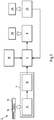
- FIG. 1 shows a first embodiment of the system according to the invention in a schematic representation.
- the system 2 for the automated support of a connection process of components arranged in a control cabinet or on a mounting system such as a mounting plate comprises a detection device 4, a visualization device 6 and an output device 8.
- the detection device 4 is set up to detect an identifier 10 of a connecting line 12.
- the detection device 4 can have, for example, a camera 14 or, alternatively, a scanner such as a laser scanner.
- the processing device 16 examines the image data recorded with the camera 14 by means of image processing techniques for the presence of an identifier for a connection line and generates a digital code for the identifier found so that the captured identifier is further processed in the form of the digital code by the visualization device 6 to generate a user output can be.
- the visualization device 6 is set up, depending on the detected identifier and a connection diagram, for example a wiring diagram 18, a visual user output 20 about the connection, for example via the wiring, of the connection line 12 identified by the identifier 10 produce.
- the connection diagram 18 can be stored, for example, on an electronic memory of the system 2 and contains information about the respective connection points and routing paths of the connecting lines to be connected.
- the visualization device 6 retrieves the information about the connection, for example about the wiring, of the connection line 12 identified using the detected identifier 10 from the connection diagram 18 and generates a corresponding graphic representation, for example with a schematic representation of the control cabinet and a highlighted representation of the identified connecting line 12 in the laid state.
- the output device 8 is finally set up to output the user output 20 generated by the visualization device 6 to a user.
- the output device 8 can have a screen, for example.
- the system 2 can also be set up to generate the user output 20 as an augmented reality display.
- the visualization device 6 for generating the user output 20 can, for example, superimpose an image captured by the camera 14 of the switch cabinet with the components to be connected, in particular wired, with a highlighted representation of the identified connecting line 12 in the connected state.
- the system 2 can also have an input device 22 which is set up to receive a user input 24 via the connection of a previously identified connection line. In this way, the system 2 can log the connection process actually carried out by the technician.
- the visualization device 6 can also be set up to generate the user output 20 via the connection of the identified connection line also depending on the previously received user input 24 via the connection of connection lines.
- the user output 20 can also include representations of further connecting lines for which user inputs 24 have been received about the routing thereof. This allows the user, for example, better orientation at the control cabinet by being able to read the position of the connecting line to be newly connected to the connecting lines 12 that are already connected from the user output 20.
- the example also includes an embodiment of the method for automated support of a connection process, in particular a wiring process, of components arranged in a switch cabinet.
- connection line 12 selects a connection line 12 from a set of pre-assembled connection lines with respective identifiers available to him for connecting components arranged in a switch cabinet and positions the identifier 10 on the selected connection line 12 in front of the camera 14 of the detection device 4, see above that the detection device 4 detects the identifier 10 of the selected connecting line 12 and generates a digital code for the identifier 10, which is transferred to the visualization device 6.
- the visualization device 6 uses the digital code for the identifier 10 from the connection diagram 18 to call information about the connection of the identifier 10 identified connecting line 12 and uses this information to generate a user output 20, for example with a graphical representation of the control cabinet and a representation of the identified connecting line 12 in the connected state.
- the generated user output 20 is then output via the output device 8, so that the technician can extract the information necessary for connecting the selected connecting line 12 and perform the connection manually.
- the technician can enter this as user input 24 on the input device 22 after the selected connection line 12 has been connected and laid.
- the technician can then select the next connection line from the set of pre-assembled connection lines and position its identifier in front of the camera 14, whereupon the previously described process run for the new connection line runs again. In this way, the technician can gradually call up the information required for laying the individual pre-assembled connection lines automatically, so that laying errors are avoided.
- the visualization device 6 can take this into account when generating the user output 20, for example by also showing the connection lines already laid in the graphical representation of the control cabinet in order to simulate the real view of the control cabinet in this way and to simplify the connection of the current connection line 12 for the technician.
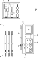
- FIG. 10 shows a further exemplary embodiment of a system 32 for the automated support of a connection process, in particular a wiring process, from FIG Components arranged in a switch cabinet 34 with a quantity 36 of pre-assembled connection lines 38.
- the connection lines 38 can, for example, have been defined in advance on the basis of a virtual routing on a virtual model of the switch cabinet 34 and then correspondingly assembled. In this way, before the start of the connection process, the technician has the connection lines 38 required for this, each with the correct type and length and, if necessary, with the correct connections.
- the individual connecting lines 38 are each printed with identifiers 40 by means of which the connecting lines 38 can be distinguished from one another.
- the identifiers 40 preferably allow a unique identification of the individual connecting lines 38 within the set 36.
- the identifiers 40 are shown as an example as a barcode. However, other identifiers are also conceivable, for example character strings printed on the connecting lines 38.
- the system 32 for supporting the connection process comprises a mobile device 46, for example in the form of a smartphone or a tablet computer, with a camera module 48, a user interface 50 in the form of a touchscreen and a control device 52 with at least one processor 54 and an electronic device connected to it Memory 56 and interfaces 58 and 60 for communication with the camera module 48 and the touchscreen 50.
- a computer program is stored in the memory 56 of the control device 52, the execution of which on the at least one processor 54 of the control device 52 enables a method to automatically support a connection process the components arranged in the control cabinet 34 causes.
- the camera 48 is set up to capture image data and the control device 52 is set up, when executing the computer program stored in the memory 56, to analyze the image data received via the interface 58 from the camera 48 to determine whether it has an identifier 40 ′ Connection line 38 'from the set 36 and, if this is the case, to generate a digital code for the identifier 40'.
- a list with the identifiers 40 of the connecting lines 38 from the set 36 can be stored in the memory 56, so that the control device 52 can determine by comparing the generated code with the identifiers stored in the list whether the detected identifier 40 'to a connecting line 38' from the set 36 for connecting, in particular for wiring, the components arranged in the switch cabinet 34.
- the camera 48 can be set up to permanently capture image data, and the control device 52 can be set up to continuously search through the captured image data for an identifier until an identifier 40 ′ is positioned when a connecting line 38 ′ from the set 36 is in front of the camera 48 is recognized.
- the control device 52 can also be set up to search through an image captured by the camera 48 for an identifier in response to a user input via the touchscreen 50.
- connection diagram for example a wiring diagram
- the connection diagram can be stored in the form of a virtual model of the control cabinet 34 which, in addition to information about the control cabinet, for example about its dimensions and the components to be arranged or arranged therein, also contains information about the connection points and / or the routing paths of the connecting lines 38 .
- the information on the individual connecting lines 38 is preferably assigned the associated identifier 40 of the connecting line 38, so that the Control device 52 can retrieve the information for the connection line 38 currently to be connected from the connection diagram as a function of the detected identifier 40 'or the digital code for it and use it for generating the user output.
- control device 52 After the generation of the user output, the control device 52 causes it to be displayed on the touchscreen 50, so that the technician receives the information via the touchscreen 50 that he needs to connect the corresponding connecting line 38.
- the control device 52 forms a program part of the computer program on the memory 56 with the program part of the computer program provided for generating a user output Visualization device 64 of the system 32.
- the touchscreen 50 and the control device 52 form an output device 66 of the system with the program part of the computer program provided for the output of the user output on the memory 56.
- the individual devices of the system do not necessarily have to be formed by different hardware components, but can, for example, share a common control device on which a computer program with appropriate modules for the individual devices runs.
- Figure 3 shows the touchscreen 50 with a user output 70 displayed thereon, which was generated by the control device 52 for the connecting line 38 'identified on the basis of the detected identifier 40'.
- the user output 70 includes a representation 72 of the control cabinet 34. This can, for example, have been generated by a virtual model of the control cabinet 34 stored in the memory 56.
- Representation 72 includes a representation 74 of the control cabinet itself as well as representations 76 of components 78 built into it.
- representation 72 includes a highlighted representation 80 of the identified connecting line 38 ′ in the connected, for example wired, state, so that the technician can view the user output 70 intuitive way can infer where, ie At which connection points he has to connect the selected connection line 38 'to the components 78 in the switch cabinet 34 and which routing path in the switch cabinet 34 is to be selected.
- the highlighted representation 80 with the identified connecting line 38 'in the connected state is only an example. Instead, the representation 80 could e.g. also include two arrows which indicate the position of the respective connection points of the connecting line 38 '.
- the representation 72 can also include a list representation of all connecting lines, wherein the identified connecting line 38 ′ can, for example, be highlighted and information on connecting this connecting line 38 ′ is displayed.
- Virtual buttons 82, 84 are also shown on touch screen 50, via which the user can make a user input by touching touch screen 50 in the area of one of the two buttons.
- pressing button 82 he can confirm that he has connected the connecting line 38 '; by actuating the button 84 he can cancel the process and instead select, for example, a different connection line from the set 36 of connection lines.
- the user inputs of the user via the touchscreen 50 are registered by the control device 52 and stored in the memory 56 so that the control device 52 has the information about which of the connecting lines 38 from the set 36 have already been connected. This information can be used, for example, when generating subsequent user outputs.
- the user output 70 can also include representations 86 of previously laid connection lines 88, so that the technician can intuitively infer the position of the new connection line 38 ′ relative to the connection lines 88 that have already been laid from the user output 70.
- the system 32 can also be designed for augmented reality display.
- the execution of the computer program stored on the memory 56 on the at least one processor 54 preferably causes a real image of the control cabinet 34 and the components arranged therein to be superimposed with a representation 80 of the identified connecting line 38 ' that the representation 80 shows the position of the connecting line 38 'in the laid state over the real image of the control cabinet and the components arranged therein.
- a simple screen can also be provided.
- keys for example a keyboard, a computer mouse or a touchpad, can be provided for user input.
- the system can also have data glasses, via which the user output is output.
- the data glasses can be connected to the control device 52 via a radio link, for example.
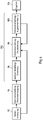
- Figure 4 shows an example of a completely digitally supported workflow from the planning of a control cabinet to the production of pre-assembled connection lines as well as the following method for the automated support of a connection process, for example a wiring process, including the detection of the connection line, the interpretation of the connection, the display of a corresponding user output, and ultimately as a result completed control cabinet.
- the Figure 4 shows in particular how the method described here and a system set up to carry out the method, such as system 2 or 32, can be inserted into such a workflow.
- a virtual model of the control cabinet to be manufactured is first generated by means of a computer program provided for this purpose, in that the virtual control cabinet is virtually equipped with the intended components and the connection lines required for connecting, in particular for wiring the individual components, in terms of their type and possibly also their laying routes are defined.
- the connection diagram for the system 2 or 32 is preferably also generated, which is later used to generate the user outputs for connecting the individual connecting lines.
- connection lines to be assembled are determined on the basis of the data model of the control cabinet generated in the first step 92 and produced on this database.
- the individual connecting lines are each provided with individual identifiers, for example by printing a numerical label or a barcode, by means of which the individual connecting lines can be clearly identified within the set of connecting lines made up for connecting the components to be arranged or arranged in the switch cabinet.
- step 96 an identifier of a pre-assembled connecting line for connecting, in particular the wiring, of components arranged in a switch cabinet is detected by means of a detection device.
- step 98 a visual user output is generated about the connection of the connection line identified via the recorded identifier.
- the visualization takes place on the basis of the previously recorded identifier specifically for the connection line identified in step 96 and depending on the connection diagram preferably generated in step 92 (see arrow from step 92 to step 98), which is available, for example, in the form of a virtual model of the control cabinet and information on the connection points and the route of the identified connection line.
- step 100 the user output generated in step 98 is output via an output device such as a screen or data glasses.
- the output is preferably carried out as an augmented reality representation so that the user can provide the work instructions required for the manual laying of the identified connection line, i.e. the connection points and the routing of the connection line concerned can be recorded intuitively and in spatial relation to the real control cabinet.
- Steps 96, 98 and 100 are repeated one after the other for the individual pre-assembled connection lines until finally, in step 104, as a result of the entire method, the switch cabinet with the completely connected, in particular wired, components arranged therein is completed.
- the user of the system can preferably confirm the connection of the respective connecting line in step 100 via an input device.
- This information is transmitted to the visualization device so that it can take into account the information about connecting lines that have already been laid when generating user outputs of subsequently identified connecting lines (cf. arrow from step 100 to step 98).
- the method for the automated support of a connection process of components arranged in a switch cabinet or on a mounting system, such as a mounting plate, can in particular also include preparatory steps 92 and 94, in which the connection diagram and the pre-assembled connection lines are generated.
- the entire method from step 92 to 104 represents an example of a method for connecting, in particular for wiring, of in a control cabinet or on a mounting system, e.g.
- a completely digitally supported workflow is created from the planning to the assembly of the connecting cables, their detection and interpretation to the connection of the connecting cables to the components in the real control cabinet or the assembly system, e.g. a mounting plate.
- FIG. 5 shows an embodiment of a detection unit not belonging to the invention for detecting an identifier 40 'of a connecting line 38'.
- the detection unit 110 comprises a receptacle 112 into which a connecting line 38 ′ to be identified can be inserted.
- a camera module 114 is arranged, with which image data can be captured from a connecting line 38 ′ inserted in the receptacle 112.
- the receptacle 112 is designed in the form of a channel-shaped cavity that is open on both sides, so that the connecting line 38 ′ can be pushed into the receptacle 112. Since the receptacle 112 is open on both sides, the connecting line 38 'can be pushed into the receptacle 112 until the identifier 40' of the connecting line 38 'can be detected by the camera module 114. As a result, the identifier 40 'can be recorded independently of its position on the connecting line 38'.
- the receptacle 112 can also only be opened on one side, in particular if the identifier 40 'is at a predetermined position of the connecting line 38' is provided, for example at a certain distance from one end of the connecting line 38 '.
- the depth of the receptacle 112 is then preferably adapted so that the identifier 40 ′ is arranged in the field of vision of the camera module 114 when the connecting line 38 ′ is pushed into the receptacle 112 as far as it will go.
- the receptacle 112 preferably has an expression in the form of an edge and the camera module 114 is preferably arranged such that the edge lies in the field of view of the camera module 114.
- the receptacle 112 can have a triangular cross section or be prism-shaped, with a corner of the triangle or an edge of the prism shape lying in the field of view of the camera module 114.
- a defined contact point for the connecting line 38 ′ is predetermined by the edge, whereby the positioning of the connecting line 38 ′ in the receptacle and the identifier 40 ′ in the field of view of the camera module 114 is facilitated.
- the detection unit 110 also has an illumination device 116 with which the receptacle 112 in the area of the camera module 114 can be illuminated so that the identifier 40 ′ can be reliably detected independently of the external light conditions.
- the lighting device 116 preferably extends transversely to the longitudinal extent of the receptacle 112 in such a way that at least 180 ° of the curved surface of a connecting line arranged in the receptacle 112 is illuminated so that the identifier printed on the curved surface of a connecting line can be reliably detected.
- the acquisition unit can optionally have a screen 138 on which the image acquired by the camera module 114 is output in order to make it easier for the technician to position the connecting line 38 ′ in the receptacle 112. In particular, the technician can thereby position the identifier 40 ′ more easily in the field of view of the camera module 114.
- the acquisition unit 110 also has a control device 118 which is set up to find an identifier 40 'of a connecting line 38' in the acquired image data and to generate a digital code for the identifier found.
- the control device 118 can also control the function of the camera module 114 and the lighting device 116.
- the detection unit 110 has a transmission device 120 which is set up to transmit the digital code for the identifier 40 'found to a visualization device for generating a user output by connecting the connection line identified by the identifier.
- the transmission device 120 is set up in the present case to transmit the digital code for the identifier 40 ′ to a server 130 which has a control device 132 on which a computer program for generating a visual user output runs as a function of the digital code.
- the transmission device 120 in the detection unit 110 is formed on the one hand by a network interface 122, for example a LAN or WLAN interface, and by a part of the computer program running on the control device 118 that enables the transmission of the digital code for the identifier via the network interface 122 and a network 142 to the server 130.
- a network interface 122 for example a LAN or WLAN interface
- the control device 118 that enables the transmission of the digital code for the identifier via the network interface 122 and a network 142 to the server 130.
- the server 130 which has a corresponding network interface 134 for receiving the digital code, can then use the transmitted digital code for the identifier 40 'and a connection diagram stored in a memory of the server 130, which for example contains a virtual model of the control cabinet with the therein arranged components to be connected can generate a user output by connecting the connecting line 38 'identified by means of the identifier 40'.
- the generated user output can then be output on a screen 136 of the server 130.
- the user output can also be output via data glasses that are coupled to the server 130 or to the acquisition unit 110 via a wired or wireless communication link.
- the generated user output is transmitted from the server 130 to the acquisition unit 110 and output via an optionally provided screen 138 of the acquisition unit 110.
- the acquisition unit 110 and the server 130 together form a system 144 for the automated support of a connection process in a switch cabinet or on a mounting system, e.g. a mounting plate, arranged components.
- the user output can also be generated in the acquisition unit 110 itself.
- the control device 118 can be set up to generate a user output depending on the generated code for the identifier 40 'and a connection diagram stored in a memory of the control device 118 and e.g. to be output via the screen 138 of the acquisition unit 110 or via data glasses connected to it by means of a communication link.
- the control device 118 represents the visualization device with part of the computer program running on it to generate the user output.
- the transmission of the digital code to the visualization device takes place in this case purely on the software side, the control device and a corresponding program part representing the transmission device.
- the detection unit 110 is designed as a stationary device that can be set up on site near the switch cabinet to be connected.
- the detection unit 110 preferably comprises a suitable housing 140 in which the individual components of the detection unit 110 are accommodated.
Claims (11)
- Procédé d'assistance automatisée d'un processus de branchement, plus particulièrement d'un processus de câblage de composants disposés dans une armoire de commande (34), dans lequel, au moyen d'un dispositif de détection (4, 62), un identifiant (10, 40, 40') d'une ligne de raccordement (12, 38, 38', 52) est détecté parmi une quantité de lignes de raccordement pré-confectionnées (12, 38, 38', 52), pour le branchement, plus particulièrement pour le câblage, de composants disposés dans l'armoire de commande (34), moyennant quoi l'identifiant (10, 40, 40') identifie la ligne de raccordement (12, 38, 38', 52), dans lequel, en fonction de l'identifiant (10, 40, 40') et d'un plan de branchement, plus particulièrement un plan de câblage (18), une sortie utilisateur visuelle (20, 70) est automatiquement générée concernant le branchement, plus particulièrement le câblage, de la ligne de raccordement (12, 38, 38', 52) identifiée par l'identifiant (10, 40, 40') et dans lequel la sortie utilisateur (20, 70) générée est émise par l'intermédiaire d'un dispositif de sortie (8, 66), caractérisé en ce que la production de la sortie utilisateur visuelle (20, 70) comprend la production d'une représentation graphique des points de branchement et du trajet de pose de la ligne de raccordement (12, 38, 38', 52).
- Procédé selon la revendication 1, caractérisé en ce que la sortie utilisateur (20, 70) est générée au moyen d'un modèle virtuel de l'armoire de commande (34) avec une représentation du branchement, plus particulièrement du câblage, de la ligne de raccordement (12, 38, 38', 52) identifiée.
- Procédé selon l'une des revendications 1 ou 2, caractérisé en ce que la sortie utilisateur (20, 70) est émise par l'intermédiaire d'un appareil à réalité augmentée, plus particulièrement d'un écran (50, 136, 138) ou des lunettes de données, moyennant quoi une image réelle ou un objet réel est superposé avec la sortie utilisateur (20, 70) générée.
- Procédé selon l'une des revendications 1 à 3, dans lequel une entrée utilisateur (24) concernant le branchement effectué, plus particulièrement concernant le câblage effectué, d'une autre ligne de raccordement (88) identifiée à un moment antérieur, est reçue et dans lequel la sortie utilisateur (20, 70) concernant le branchement, plus particulièrement concernant le câblage, de la ligne de raccordement (12, 38, 38', 52) est générée en fonction de l'entrée utilisateur (24) concernant le branchement effectué, plus particulièrement concernant le câblage effectué, de l'autre ligne de raccordement (88).
- Système (2, 32) pour l'assistance automatisée d'un processus de branchement, plus particulièrement d'un processus de câblage, de composants disposés dans une armoire de commande (34), plus particulièrement pour la réalisation d'un procédé selon l'une des revendications 1 à 4, avec un dispositif de détection (4, 62, 110) qui est conçu pour détecter un identifiant (10, 40, 40') d'une ligne de raccordement (12, 38, 38', 52), moyennant quoi l'identifiant (10, 40, 40') identifie la ligne de raccordement (12, 38, 38', 52) avec un dispositif de visualisation (8, 64), qui est conçu pour générer, en fonction de l'identifiant (10, 40, 40') détecté et d'un plan de branchement, plus particulièrement d'un plan de câblage (18), une sortie utilisateur visuelle (20, 70) concernant le branchement, plus particulièrement concernant le câblage, de la ligne de raccordement (12, 38, 38', 52) identifiée et, avec un dispositif de sortie (8, 66), qui est conçu pour émettre la sortie utilisateur (20, 70) générée par le dispositif de visualisation à l'attention d'un utilisateur, comprenant en outre une quantité (36) de lignes de raccordement (12, 38, 38', 52) pré-confectionnées, pour le branchement, plus particulièrement pour le câblage, de composants disposés dans l'armoire de commande (34), moyennant quoi chaque ligne de raccordement (12, 38, 38', 52) comprend un identifiant (10, 40, 40') pour l'identification de la ligne de raccordement (12, 38, 38', 52) respective, caractérisé en ce que la sortie utilisateur visuelle (20, 70) comprend une représentation graphique des points de branchement et du trajet de pose de la ligne de raccordement (12, 38, 38', 52).
- Système selon la revendication 5, caractérisé en ce que le dispositif de visualisation (8, 64) est conçu pour générer la sortie utilisateur (20, 70) au moyen d'un modèle virtuel de l'armoire de commande (34), une sortie utilisateur visuelle (20, 70) avec une représentation du branchement, plus particulièrement du câblage de la ligne de raccordement (12, 38, 38', 52) identifiée.
- Système selon l'une des revendications 5 ou 6, comprenant un appareil à réalité augmentée qui est conçu pour l'émission de la sortie utilisateur (20, 70) à l'attention d'un utilisateur, moyennant quoi une image réelle ou un objet réel est superposé avec la sortie utilisateur (20, 70) générée.
- Système selon l'une des revendications 5 à 7, comprenant en outre un dispositif d'entrée (22, 50) qui est conçu pour recevoir des entrées utilisateurs (24) concernant le branchement effectué, plus particulièrement le câblage effectué, de lignes de raccordement (88) identifiées, moyennant quoi le dispositif de visualisation (8, 64) est conçu pour générer la sortie utilisateur (20, 70) concernant le branchement, plus particulièrement concernant le câblage, d'une ligne de raccordement (12, 38, 38', 52) identifiée, en fonction d'entrées utilisateurs (24) concernant le branchement effectué, plus particulièrement le câblage effectué, d'autres lignes de raccordement (88) identifiées auparavant.
- Système selon l'une des revendications 5 à 8, comprenant en outre un dispositif de commande (52, 118) qui est conçu pour provoquer l'exécution d'un procédé selon l'une des revendications 1 à 5.
- Utilisation d'un système (2, 32) selon l'une des revendications 5 à 9, pour l'assistance automatisée d'un processus de câblage de composants disposés dans l'armoire de commande (34).
- Programme informatique comprenant des instructions qui font en sorte que le dispositif de la revendication 5 exécuter les étapes du procédé selon l'une des revendications 1 à 4.
Priority Applications (6)
| Application Number | Priority Date | Filing Date | Title |
|---|---|---|---|
| PL17167566T PL3392987T3 (pl) | 2017-04-21 | 2017-04-21 | Sposób i system zautomatyzowanego wspomagania procesu łączenia, w szczególności dla elementów w szafie rozdzielczej lub na systemie montażowym |
| EP17167566.3A EP3392987B1 (fr) | 2017-04-21 | 2017-04-21 | Procédé et système d'assistance automatisée d'un processus de raccordement, en particulier de composants disposés dans une armoire électrique ou sur un système de montage |
| CN201880026134.7A CN110546836B (zh) | 2017-04-21 | 2018-03-23 | 用于对连接工艺进行自动化支持的方法和系统 |
| PCT/DE2018/100267 WO2018192613A1 (fr) | 2017-04-21 | 2018-03-23 | Procédé et système de prise en charge automatique d'un processus de connexion, en particulier de composants installés dans une armoire électrique ou sur un système de montage |
| JP2019556893A JP6849821B2 (ja) | 2017-04-21 | 2018-03-23 | 特にスイッチキャビネット内または組立システム上に配置された部品の、接続作業の自動的なサポート方法およびサポート用システム |
| US16/606,694 US20200136356A1 (en) | 2017-04-21 | 2018-03-23 | Method and system for the automated support of a connection process, in particular of components arranged in a control cabinet or on a mounting system |
Applications Claiming Priority (1)
| Application Number | Priority Date | Filing Date | Title |
|---|---|---|---|
| EP17167566.3A EP3392987B1 (fr) | 2017-04-21 | 2017-04-21 | Procédé et système d'assistance automatisée d'un processus de raccordement, en particulier de composants disposés dans une armoire électrique ou sur un système de montage |
Publications (2)
| Publication Number | Publication Date |
|---|---|
| EP3392987A1 EP3392987A1 (fr) | 2018-10-24 |
| EP3392987B1 true EP3392987B1 (fr) | 2020-12-02 |
Family
ID=58671377
Family Applications (1)
| Application Number | Title | Priority Date | Filing Date |
|---|---|---|---|
| EP17167566.3A Active EP3392987B1 (fr) | 2017-04-21 | 2017-04-21 | Procédé et système d'assistance automatisée d'un processus de raccordement, en particulier de composants disposés dans une armoire électrique ou sur un système de montage |
Country Status (6)
| Country | Link |
|---|---|
| US (1) | US20200136356A1 (fr) |
| EP (1) | EP3392987B1 (fr) |
| JP (1) | JP6849821B2 (fr) |
| CN (1) | CN110546836B (fr) |
| PL (1) | PL3392987T3 (fr) |
| WO (1) | WO2018192613A1 (fr) |
Families Citing this family (6)
| Publication number | Priority date | Publication date | Assignee | Title |
|---|---|---|---|---|
| DE102018109599B3 (de) | 2018-04-20 | 2019-07-18 | Rittal Gmbh & Co. Kg | Schaltschrankgehäuse mit Bauteilkennzeichnung sowie ein entsprechendes Herstellungsverfahren |
| DE102018133337A1 (de) | 2018-12-21 | 2020-06-25 | Rittal Gmbh & Co. Kg | Verfahren zur Verdrahtung von elektrischen Komponenten einer auf einer Montageplatte angeordneten elektrischen Schaltanlage |
| DE102018133319A1 (de) | 2018-12-21 | 2020-06-25 | Rittal Gmbh & Co. Kg | Verfahren zur robotergestützten Verdrahtung von elektrischen Komponenten einer auf einer Montageplatte angeordneten elektrischen Schaltanlage |
| US11295135B2 (en) | 2020-05-29 | 2022-04-05 | Corning Research & Development Corporation | Asset tracking of communication equipment via mixed reality based labeling |
| US11374808B2 (en) | 2020-05-29 | 2022-06-28 | Corning Research & Development Corporation | Automated logging of patching operations via mixed reality based labeling |
| US20220100181A1 (en) * | 2020-09-28 | 2022-03-31 | Rockwell Automation Technologies, Inc. | Wiring diagram manager and emulator |
Family Cites Families (18)
| Publication number | Priority date | Publication date | Assignee | Title |
|---|---|---|---|---|
| JP2641588B2 (ja) * | 1990-03-09 | 1997-08-13 | 株式会社日立製作所 | 電力機器およびその異常標定方法 |
| US6272387B1 (en) * | 1998-11-06 | 2001-08-07 | The Boeing Company | Wire harness system |
| DE19918212A1 (de) * | 1999-04-22 | 2000-11-09 | Cad Cabel Inh Peter Hanzel | Kabel zur Verdrahtung von elektrischen Geräten einer komplexen, individuellen Anlage und Verfahren zu deren Herstellung |
| JP4843441B2 (ja) * | 2006-09-29 | 2011-12-21 | 株式会社東芝 | 製造検査支援装置、製造検査支援方法およびそのプログラム |
| CN102447229B (zh) * | 2010-10-12 | 2015-11-25 | 胜德国际研发股份有限公司 | 电力信息显示界面、显示方法与其装置 |
| JP5564444B2 (ja) * | 2011-01-25 | 2014-07-30 | 株式会社日立製作所 | 配線作業指示方法 |
| EP2850609A4 (fr) * | 2012-05-16 | 2017-01-11 | Mobile Augmented Reality Ltd. Imagine | Système porté par un utilisateur mobile pour augmenter complètement la réalité par ancrage d'objets virtuels |
| ES2443265B1 (es) * | 2012-08-16 | 2014-11-13 | Eads Construcciones Aeronauticas, S.A. | Banco de fabricación o verificación de mazos eléctricos |
| JP5596102B2 (ja) * | 2012-10-31 | 2014-09-24 | 株式会社日立産機システム | 災害時の電力系統の異常事態に対応可能な電力買取システム用系統連系装置、及び当該電力買取システム用系統連系装置を用いた災害等の緊急避難時における電力の緊急出力方法 |
| JP2015061339A (ja) * | 2013-09-17 | 2015-03-30 | 株式会社日立製作所 | 結線作業支援システム |
| CN105430255A (zh) * | 2014-09-16 | 2016-03-23 | 精工爱普生株式会社 | 图像处理装置以及机器人系统 |
| JP6554811B2 (ja) * | 2015-02-17 | 2019-08-07 | 株式会社デンソー | 制御装置 |
| DE102015007624A1 (de) * | 2015-06-16 | 2016-12-22 | Liebherr-Components Biberach Gmbh | Verfahren zum Montieren von elektrischen Schaltanlagen sowie Montagehilfsvorrichtung zum Erleichtern der Montage solcher Schaltanlagen |
| US9852500B2 (en) * | 2015-07-15 | 2017-12-26 | GM Global Technology Operations LLC | Guided inspection of an installed component using a handheld inspection device |
| JP6369428B2 (ja) * | 2015-09-11 | 2018-08-08 | 日立金属株式会社 | ワイヤーハーネス組立品の検査方法 |
| CN105429027B (zh) * | 2015-11-12 | 2017-08-18 | 国网宁夏电力公司 | 智能变电站运维检修中二次安全措施支持系统及构建方法 |
| CN105846330B (zh) * | 2016-05-30 | 2017-12-19 | 国网河南省电力公司电力科学研究院 | 用于避雷器带电更换泄漏电流表专用成套工具及作业方法 |
| CN106340818B (zh) * | 2016-10-17 | 2018-03-27 | 南京国电南自电网自动化有限公司 | 智能变电站继电保护设备检修安措辅助分析预警方法 |
-
2017
- 2017-04-21 EP EP17167566.3A patent/EP3392987B1/fr active Active
- 2017-04-21 PL PL17167566T patent/PL3392987T3/pl unknown
-
2018
- 2018-03-23 US US16/606,694 patent/US20200136356A1/en not_active Abandoned
- 2018-03-23 CN CN201880026134.7A patent/CN110546836B/zh active Active
- 2018-03-23 WO PCT/DE2018/100267 patent/WO2018192613A1/fr active Application Filing
- 2018-03-23 JP JP2019556893A patent/JP6849821B2/ja active Active
Non-Patent Citations (1)
| Title |
|---|
| None * |
Also Published As
| Publication number | Publication date |
|---|---|
| CN110546836A (zh) | 2019-12-06 |
| EP3392987A1 (fr) | 2018-10-24 |
| WO2018192613A1 (fr) | 2018-10-25 |
| JP6849821B2 (ja) | 2021-03-31 |
| PL3392987T3 (pl) | 2021-06-14 |
| US20200136356A1 (en) | 2020-04-30 |
| CN110546836B (zh) | 2021-08-24 |
| JP2020518217A (ja) | 2020-06-18 |
Similar Documents
| Publication | Publication Date | Title |
|---|---|---|
| EP3392987B1 (fr) | Procédé et système d'assistance automatisée d'un processus de raccordement, en particulier de composants disposés dans une armoire électrique ou sur un système de montage | |
| EP3477804B1 (fr) | Procédé de montage et de câblage des installations de commutation électriques ainsi que dispositif d'aide au montage en réalité virtuelle destiné à faciliter le montage de telles installations de commutation | |
| DE10159610B4 (de) | System und Verfahren zur Erstellung einer Dokumentation von Arbeitsvorgängen, insbesondere im Umfeld Produktion, Montage, Service oder Wartung | |
| EP2524329B1 (fr) | Agencement et procédé pour vérifier un modèle réel en utilisant un modèle virtuel et utilisation associée dans la construction aéronautique | |
| DE102006014634B4 (de) | Mensch-Maschine-Schnittstelle für ein Kontroll- bzw. Steuerungs-System | |
| EP1183578B1 (fr) | Systeme a realite amplifiee pour l'assistance conforme a la situation de l'interaction entre un utilisateur et un dispositif technique | |
| DE10041104C1 (de) | Einrichtung und Verfahren zur Kommunikation zwischen einer mobilen Datenverarbeitungsvorrichtung und einer stationären Datenverarbeitungsvorrichtung | |
| EP3452928B1 (fr) | Procede et systeme de configuration d'une armoire electrique | |
| EP3605758B1 (fr) | Dispositif et procédé de vérification d'un contenu d'armoire de distribution après un montage planifié | |
| DE102007013324A1 (de) | Verfahren zur Erfassung wenigstens eines Bestandteils einer medizintechnischen Anlage sowie zugehörige medizintechnische Anlage | |
| DE69906914T2 (de) | Fernassistent | |
| DE19546223A1 (de) | Verfahren und Managementsystem zum Management von räumlich getrennten Objekten | |
| DE102008048985A1 (de) | Verfahren zur Prüfung eines Automatisierungssystems und Prüfgerät zum Prüfen eines Automatisierungssystems | |
| EP1655663A1 (fr) | Modélisation d'un flux de données dans les systèmes d'ingénierie | |
| DE102004010203B4 (de) | Verfahren, Vorrichtung und Computerprogramm zur Erstellung einer Projektierung für ein Bediengerät einer Automatisierungskomponente | |
| EP3847516B1 (fr) | Identification des contrôleurs dans un système d'automatisation | |
| AT522653A1 (de) | Verfahren zur Darstellung und Bedienung von Produktionsmitteln, insbesondere für die kunststoffverarbeitende Industrie | |
| WO2024068413A1 (fr) | Procédé d'installation assistée par ordinateur de composants électriques disposés de manière décentralisée dans l'espace d'une machine | |
| WO2024068742A1 (fr) | Procédé d'installation assistée par ordinateur de composants spatialement décentralisés d'une machine | |
| EP4345554A1 (fr) | Procédé d'installation assistée par ordinateur de composants électriques d'une machine agencés de manière décentralisée dans l'espace | |
| EP4345547A1 (fr) | Procédé d'installation assistée par ordinateur de composants électriques d'une machine agencés de manière décentralisée dans l'espace | |
| WO2024068855A1 (fr) | Procédé d'installation assistée par ordinateur de composants électriques, disposés de manière décentralisée dans l'espace, d'une machine, par de multiples utilisateurs avec un support spécifique | |
| EP2839348B1 (fr) | Procédé de configuration d'un système d'automatisme | |
| EP1993014B1 (fr) | Procédé de localisation de composants matériels défectueux et/ou d'erreurs systèmes à l'intérieur d'une installation de production | |
| EP1724688A1 (fr) | Procédé de vérification automatique d'une structure d'actionnement |
Legal Events
| Date | Code | Title | Description |
|---|---|---|---|
| PUAI | Public reference made under article 153(3) epc to a published international application that has entered the european phase |
Free format text: ORIGINAL CODE: 0009012 |
|
| STAA | Information on the status of an ep patent application or granted ep patent |
Free format text: STATUS: THE APPLICATION HAS BEEN PUBLISHED |
|
| AK | Designated contracting states |
Kind code of ref document: A1 Designated state(s): AL AT BE BG CH CY CZ DE DK EE ES FI FR GB GR HR HU IE IS IT LI LT LU LV MC MK MT NL NO PL PT RO RS SE SI SK SM TR |
|
| AX | Request for extension of the european patent |
Extension state: BA ME |
|
| STAA | Information on the status of an ep patent application or granted ep patent |
Free format text: STATUS: REQUEST FOR EXAMINATION WAS MADE |
|
| 17P | Request for examination filed |
Effective date: 20190424 |
|
| RBV | Designated contracting states (corrected) |
Designated state(s): AL AT BE BG CH CY CZ DE DK EE ES FI FR GB GR HR HU IE IS IT LI LT LU LV MC MK MT NL NO PL PT RO RS SE SI SK SM TR |
|
| STAA | Information on the status of an ep patent application or granted ep patent |
Free format text: STATUS: EXAMINATION IS IN PROGRESS |
|
| 17Q | First examination report despatched |
Effective date: 20200124 |
|
| GRAP | Despatch of communication of intention to grant a patent |
Free format text: ORIGINAL CODE: EPIDOSNIGR1 |
|
| STAA | Information on the status of an ep patent application or granted ep patent |
Free format text: STATUS: GRANT OF PATENT IS INTENDED |
|
| INTG | Intention to grant announced |
Effective date: 20200723 |
|
| GRAS | Grant fee paid |
Free format text: ORIGINAL CODE: EPIDOSNIGR3 |
|
| GRAA | (expected) grant |
Free format text: ORIGINAL CODE: 0009210 |
|
| STAA | Information on the status of an ep patent application or granted ep patent |
Free format text: STATUS: THE PATENT HAS BEEN GRANTED |
|
| AK | Designated contracting states |
Kind code of ref document: B1 Designated state(s): AL AT BE BG CH CY CZ DE DK EE ES FI FR GB GR HR HU IE IS IT LI LT LU LV MC MK MT NL NO PL PT RO RS SE SI SK SM TR |
|
| REG | Reference to a national code |
Ref country code: GB Ref legal event code: FG4D Free format text: NOT ENGLISH |
|
| REG | Reference to a national code |
Ref country code: AT Ref legal event code: REF Ref document number: 1341961 Country of ref document: AT Kind code of ref document: T Effective date: 20201215 Ref country code: CH Ref legal event code: NV Representative=s name: KAMINSKI HARMANN PATENTANWAELTE AG, LI Ref country code: CH Ref legal event code: EP |
|
| REG | Reference to a national code |
Ref country code: IE Ref legal event code: FG4D Free format text: LANGUAGE OF EP DOCUMENT: GERMAN |
|
| REG | Reference to a national code |
Ref country code: DE Ref legal event code: R096 Ref document number: 502017008424 Country of ref document: DE |
|
| PG25 | Lapsed in a contracting state [announced via postgrant information from national office to epo] |
Ref country code: RS Free format text: LAPSE BECAUSE OF FAILURE TO SUBMIT A TRANSLATION OF THE DESCRIPTION OR TO PAY THE FEE WITHIN THE PRESCRIBED TIME-LIMIT Effective date: 20201202 Ref country code: NO Free format text: LAPSE BECAUSE OF FAILURE TO SUBMIT A TRANSLATION OF THE DESCRIPTION OR TO PAY THE FEE WITHIN THE PRESCRIBED TIME-LIMIT Effective date: 20210302 Ref country code: GR Free format text: LAPSE BECAUSE OF FAILURE TO SUBMIT A TRANSLATION OF THE DESCRIPTION OR TO PAY THE FEE WITHIN THE PRESCRIBED TIME-LIMIT Effective date: 20210303 Ref country code: FI Free format text: LAPSE BECAUSE OF FAILURE TO SUBMIT A TRANSLATION OF THE DESCRIPTION OR TO PAY THE FEE WITHIN THE PRESCRIBED TIME-LIMIT Effective date: 20201202 |
|
| REG | Reference to a national code |
Ref country code: NL Ref legal event code: MP Effective date: 20201202 |
|
| PG25 | Lapsed in a contracting state [announced via postgrant information from national office to epo] |
Ref country code: SE Free format text: LAPSE BECAUSE OF FAILURE TO SUBMIT A TRANSLATION OF THE DESCRIPTION OR TO PAY THE FEE WITHIN THE PRESCRIBED TIME-LIMIT Effective date: 20201202 Ref country code: LV Free format text: LAPSE BECAUSE OF FAILURE TO SUBMIT A TRANSLATION OF THE DESCRIPTION OR TO PAY THE FEE WITHIN THE PRESCRIBED TIME-LIMIT Effective date: 20201202 Ref country code: BG Free format text: LAPSE BECAUSE OF FAILURE TO SUBMIT A TRANSLATION OF THE DESCRIPTION OR TO PAY THE FEE WITHIN THE PRESCRIBED TIME-LIMIT Effective date: 20210302 |
|
| PG25 | Lapsed in a contracting state [announced via postgrant information from national office to epo] |
Ref country code: NL Free format text: LAPSE BECAUSE OF FAILURE TO SUBMIT A TRANSLATION OF THE DESCRIPTION OR TO PAY THE FEE WITHIN THE PRESCRIBED TIME-LIMIT Effective date: 20201202 Ref country code: HR Free format text: LAPSE BECAUSE OF FAILURE TO SUBMIT A TRANSLATION OF THE DESCRIPTION OR TO PAY THE FEE WITHIN THE PRESCRIBED TIME-LIMIT Effective date: 20201202 |
|
| REG | Reference to a national code |
Ref country code: LT Ref legal event code: MG9D |
|
| PG25 | Lapsed in a contracting state [announced via postgrant information from national office to epo] |
Ref country code: PT Free format text: LAPSE BECAUSE OF FAILURE TO SUBMIT A TRANSLATION OF THE DESCRIPTION OR TO PAY THE FEE WITHIN THE PRESCRIBED TIME-LIMIT Effective date: 20210405 Ref country code: SK Free format text: LAPSE BECAUSE OF FAILURE TO SUBMIT A TRANSLATION OF THE DESCRIPTION OR TO PAY THE FEE WITHIN THE PRESCRIBED TIME-LIMIT Effective date: 20201202 Ref country code: RO Free format text: LAPSE BECAUSE OF FAILURE TO SUBMIT A TRANSLATION OF THE DESCRIPTION OR TO PAY THE FEE WITHIN THE PRESCRIBED TIME-LIMIT Effective date: 20201202 Ref country code: CZ Free format text: LAPSE BECAUSE OF FAILURE TO SUBMIT A TRANSLATION OF THE DESCRIPTION OR TO PAY THE FEE WITHIN THE PRESCRIBED TIME-LIMIT Effective date: 20201202 Ref country code: EE Free format text: LAPSE BECAUSE OF FAILURE TO SUBMIT A TRANSLATION OF THE DESCRIPTION OR TO PAY THE FEE WITHIN THE PRESCRIBED TIME-LIMIT Effective date: 20201202 Ref country code: SM Free format text: LAPSE BECAUSE OF FAILURE TO SUBMIT A TRANSLATION OF THE DESCRIPTION OR TO PAY THE FEE WITHIN THE PRESCRIBED TIME-LIMIT Effective date: 20201202 Ref country code: LT Free format text: LAPSE BECAUSE OF FAILURE TO SUBMIT A TRANSLATION OF THE DESCRIPTION OR TO PAY THE FEE WITHIN THE PRESCRIBED TIME-LIMIT Effective date: 20201202 |
|
| REG | Reference to a national code |
Ref country code: DE Ref legal event code: R097 Ref document number: 502017008424 Country of ref document: DE |
|
| PG25 | Lapsed in a contracting state [announced via postgrant information from national office to epo] |
Ref country code: IS Free format text: LAPSE BECAUSE OF FAILURE TO SUBMIT A TRANSLATION OF THE DESCRIPTION OR TO PAY THE FEE WITHIN THE PRESCRIBED TIME-LIMIT Effective date: 20210402 |
|
| PLBE | No opposition filed within time limit |
Free format text: ORIGINAL CODE: 0009261 |
|
| STAA | Information on the status of an ep patent application or granted ep patent |
Free format text: STATUS: NO OPPOSITION FILED WITHIN TIME LIMIT |
|
| PG25 | Lapsed in a contracting state [announced via postgrant information from national office to epo] |
Ref country code: AL Free format text: LAPSE BECAUSE OF FAILURE TO SUBMIT A TRANSLATION OF THE DESCRIPTION OR TO PAY THE FEE WITHIN THE PRESCRIBED TIME-LIMIT Effective date: 20201202 |
|
| 26N | No opposition filed |
Effective date: 20210903 |
|
| PG25 | Lapsed in a contracting state [announced via postgrant information from national office to epo] |
Ref country code: SI Free format text: LAPSE BECAUSE OF FAILURE TO SUBMIT A TRANSLATION OF THE DESCRIPTION OR TO PAY THE FEE WITHIN THE PRESCRIBED TIME-LIMIT Effective date: 20201202 Ref country code: DK Free format text: LAPSE BECAUSE OF FAILURE TO SUBMIT A TRANSLATION OF THE DESCRIPTION OR TO PAY THE FEE WITHIN THE PRESCRIBED TIME-LIMIT Effective date: 20201202 Ref country code: MC Free format text: LAPSE BECAUSE OF FAILURE TO SUBMIT A TRANSLATION OF THE DESCRIPTION OR TO PAY THE FEE WITHIN THE PRESCRIBED TIME-LIMIT Effective date: 20201202 |
|
| GBPC | Gb: european patent ceased through non-payment of renewal fee |
Effective date: 20210421 |
|
| PG25 | Lapsed in a contracting state [announced via postgrant information from national office to epo] |
Ref country code: LU Free format text: LAPSE BECAUSE OF NON-PAYMENT OF DUE FEES Effective date: 20210421 |
|
| REG | Reference to a national code |
Ref country code: BE Ref legal event code: MM Effective date: 20210430 |
|
| PG25 | Lapsed in a contracting state [announced via postgrant information from national office to epo] |
Ref country code: GB Free format text: LAPSE BECAUSE OF NON-PAYMENT OF DUE FEES Effective date: 20210421 Ref country code: ES Free format text: LAPSE BECAUSE OF FAILURE TO SUBMIT A TRANSLATION OF THE DESCRIPTION OR TO PAY THE FEE WITHIN THE PRESCRIBED TIME-LIMIT Effective date: 20201202 |
|
| PG25 | Lapsed in a contracting state [announced via postgrant information from national office to epo] |
Ref country code: IE Free format text: LAPSE BECAUSE OF NON-PAYMENT OF DUE FEES Effective date: 20210421 |
|
| PG25 | Lapsed in a contracting state [announced via postgrant information from national office to epo] |
Ref country code: IS Free format text: LAPSE BECAUSE OF FAILURE TO SUBMIT A TRANSLATION OF THE DESCRIPTION OR TO PAY THE FEE WITHIN THE PRESCRIBED TIME-LIMIT Effective date: 20210402 |
|
| PG25 | Lapsed in a contracting state [announced via postgrant information from national office to epo] |
Ref country code: BE Free format text: LAPSE BECAUSE OF NON-PAYMENT OF DUE FEES Effective date: 20210430 |
|
| PG25 | Lapsed in a contracting state [announced via postgrant information from national office to epo] |
Ref country code: CY Free format text: LAPSE BECAUSE OF FAILURE TO SUBMIT A TRANSLATION OF THE DESCRIPTION OR TO PAY THE FEE WITHIN THE PRESCRIBED TIME-LIMIT Effective date: 20201202 |
|
| P01 | Opt-out of the competence of the unified patent court (upc) registered |
Effective date: 20230525 |
|
| PG25 | Lapsed in a contracting state [announced via postgrant information from national office to epo] |
Ref country code: HU Free format text: LAPSE BECAUSE OF FAILURE TO SUBMIT A TRANSLATION OF THE DESCRIPTION OR TO PAY THE FEE WITHIN THE PRESCRIBED TIME-LIMIT; INVALID AB INITIO Effective date: 20170421 |
|
| PGFP | Annual fee paid to national office [announced via postgrant information from national office to epo] |
Ref country code: IT Payment date: 20230428 Year of fee payment: 7 Ref country code: FR Payment date: 20230417 Year of fee payment: 7 Ref country code: DE Payment date: 20230418 Year of fee payment: 7 Ref country code: CH Payment date: 20230502 Year of fee payment: 7 |
|
| PGFP | Annual fee paid to national office [announced via postgrant information from national office to epo] |
Ref country code: TR Payment date: 20230418 Year of fee payment: 7 Ref country code: PL Payment date: 20230407 Year of fee payment: 7 Ref country code: AT Payment date: 20230414 Year of fee payment: 7 |