EP3847516B1 - Identification des contrôleurs dans un système d'automatisation - Google Patents
Identification des contrôleurs dans un système d'automatisation Download PDFInfo
- Publication number
- EP3847516B1 EP3847516B1 EP19769033.2A EP19769033A EP3847516B1 EP 3847516 B1 EP3847516 B1 EP 3847516B1 EP 19769033 A EP19769033 A EP 19769033A EP 3847516 B1 EP3847516 B1 EP 3847516B1
- Authority
- EP
- European Patent Office
- Prior art keywords
- control devices
- identification message
- several control
- field device
- terminal
- Prior art date
- Legal status (The legal status is an assumption and is not a legal conclusion. Google has not performed a legal analysis and makes no representation as to the accuracy of the status listed.)
- Active
Links
- 238000000034 method Methods 0.000 claims description 23
- 230000003993 interaction Effects 0.000 claims description 13
- 230000001960 triggered effect Effects 0.000 claims description 6
- 238000005259 measurement Methods 0.000 claims description 3
- 230000000007 visual effect Effects 0.000 claims 1
- 238000009434 installation Methods 0.000 description 8
- 238000012360 testing method Methods 0.000 description 4
- 230000033228 biological regulation Effects 0.000 description 3
- 230000005540 biological transmission Effects 0.000 description 3
- 238000004891 communication Methods 0.000 description 3
- 230000000694 effects Effects 0.000 description 3
- 238000010295 mobile communication Methods 0.000 description 3
- 230000002093 peripheral effect Effects 0.000 description 3
- 238000004378 air conditioning Methods 0.000 description 2
- 238000006243 chemical reaction Methods 0.000 description 2
- 238000010586 diagram Methods 0.000 description 2
- 238000010438 heat treatment Methods 0.000 description 2
- 238000009423 ventilation Methods 0.000 description 2
- 210000000988 bone and bone Anatomy 0.000 description 1
- 238000010276 construction Methods 0.000 description 1
- 238000013461 design Methods 0.000 description 1
- 238000011161 development Methods 0.000 description 1
- 230000018109 developmental process Effects 0.000 description 1
- 238000003745 diagnosis Methods 0.000 description 1
- 238000005516 engineering process Methods 0.000 description 1
- 230000004807 localization Effects 0.000 description 1
- 238000012423 maintenance Methods 0.000 description 1
- 230000007257 malfunction Effects 0.000 description 1
- 230000003287 optical effect Effects 0.000 description 1
- 238000005457 optimization Methods 0.000 description 1
- 238000012545 processing Methods 0.000 description 1
- 230000001105 regulatory effect Effects 0.000 description 1
- 230000008054 signal transmission Effects 0.000 description 1
- 230000011664 signaling Effects 0.000 description 1
- 238000012549 training Methods 0.000 description 1
Images

Classifications
-
- G—PHYSICS
- G05—CONTROLLING; REGULATING
- G05B—CONTROL OR REGULATING SYSTEMS IN GENERAL; FUNCTIONAL ELEMENTS OF SUCH SYSTEMS; MONITORING OR TESTING ARRANGEMENTS FOR SUCH SYSTEMS OR ELEMENTS
- G05B19/00—Programme-control systems
- G05B19/02—Programme-control systems electric
- G05B19/418—Total factory control, i.e. centrally controlling a plurality of machines, e.g. direct or distributed numerical control [DNC], flexible manufacturing systems [FMS], integrated manufacturing systems [IMS] or computer integrated manufacturing [CIM]
-
- G—PHYSICS
- G05—CONTROLLING; REGULATING
- G05B—CONTROL OR REGULATING SYSTEMS IN GENERAL; FUNCTIONAL ELEMENTS OF SUCH SYSTEMS; MONITORING OR TESTING ARRANGEMENTS FOR SUCH SYSTEMS OR ELEMENTS
- G05B19/00—Programme-control systems
- G05B19/02—Programme-control systems electric
- G05B19/04—Programme control other than numerical control, i.e. in sequence controllers or logic controllers
- G05B19/042—Programme control other than numerical control, i.e. in sequence controllers or logic controllers using digital processors
-
- G—PHYSICS
- G05—CONTROLLING; REGULATING
- G05B—CONTROL OR REGULATING SYSTEMS IN GENERAL; FUNCTIONAL ELEMENTS OF SUCH SYSTEMS; MONITORING OR TESTING ARRANGEMENTS FOR SUCH SYSTEMS OR ELEMENTS
- G05B19/00—Programme-control systems
- G05B19/02—Programme-control systems electric
- G05B19/418—Total factory control, i.e. centrally controlling a plurality of machines, e.g. direct or distributed numerical control [DNC], flexible manufacturing systems [FMS], integrated manufacturing systems [IMS] or computer integrated manufacturing [CIM]
- G05B19/4185—Total factory control, i.e. centrally controlling a plurality of machines, e.g. direct or distributed numerical control [DNC], flexible manufacturing systems [FMS], integrated manufacturing systems [IMS] or computer integrated manufacturing [CIM] characterised by the network communication
-
- Y—GENERAL TAGGING OF NEW TECHNOLOGICAL DEVELOPMENTS; GENERAL TAGGING OF CROSS-SECTIONAL TECHNOLOGIES SPANNING OVER SEVERAL SECTIONS OF THE IPC; TECHNICAL SUBJECTS COVERED BY FORMER USPC CROSS-REFERENCE ART COLLECTIONS [XRACs] AND DIGESTS
- Y02—TECHNOLOGIES OR APPLICATIONS FOR MITIGATION OR ADAPTATION AGAINST CLIMATE CHANGE
- Y02P—CLIMATE CHANGE MITIGATION TECHNOLOGIES IN THE PRODUCTION OR PROCESSING OF GOODS
- Y02P90/00—Enabling technologies with a potential contribution to greenhouse gas [GHG] emissions mitigation
- Y02P90/02—Total factory control, e.g. smart factories, flexible manufacturing systems [FMS] or integrated manufacturing systems [IMS]
Definitions
- the present invention relates to a method for determining one of several control devices in a data network of an automation system.
- the present invention relates to an automation system with a plurality of control devices, a terminal device, a data network to which the control devices and the terminal device are connected, a field device and a fieldbus to which the field device is connected to one of the control devices.
- Commissioning but also service activities in general for (building) automation systems, for example for heating, ventilation or air conditioning functionality (HVAC), requires a clear identification of the control and control devices or controllers (hereinafter summarized as control devices), for example in a commissioning tool of a (room) automation system so that, for example, the necessary commissioning tests can be carried out with the correct control device.
- a commissioning tool is a device or an application that can be used to carry out commissioning.
- Such a commissioning tool can be, for example, a specially designed end device, but also a smartphone, a tablet, a PC and the like, as well as a software application in a service or commissioning environment.
- Commissioning refers in particular to the setting of a system, system or machine. This means, in particular, measures and actions (e.g. configuration, parameterization, optimization and testing) that are necessary to make a machine or system operational or ready for use. Commissioning includes measures and activities that occur after the hardware has been installed, particularly the field devices and controllers or after installing the software to set up and test the product/system.
- control devices or controllers for room, building or other automation systems are often installed in poorly accessible locations. For example, they are installed in false ceilings, in window panels or in a false floor and are not or barely visible or accessible from the outside.
- One or more field devices that provide respective functionalities are usually connected to a control device.
- a field device refers in particular to sensors, actuators and operating devices. States of the field devices are represented in the control device (e.g. controller) by corresponding data sets or data points.
- the actuators are advantageously equipped with additional sensors in order to determine the status or feedback from the process in the controller and in the instructions and to support diagnosis in the event of malfunction.
- a commissioning tool or service tool (hereinafter referred to as a terminal device) and the control device usually takes place via a building network or data network (back bone), which is preferably based on the Internet protocol (IP).
- IP Internet protocol
- the commissioning tool can, for example, send a so-called “wink command” to a room controller via the IP BACnet network.
- the room controller can signal, for example by flashing an LED or an acoustic signal.
- the service technician may be difficult for the service technician to see or perceive this flashing or signal tone.
- the commissioning tool can establish a connection to the room controller using a unique controller serial number.
- the serial number must be known and in the Commissioning tool can be entered. However, the serial number visible on the controller often cannot be used for identification due to the hidden assembly.
- the commissioning tool can also be physically connected directly to the room controller on site (for example with a USB cable). This means that the room controller can be clearly identified. This procedure also depends on the installation location and the accessibility of the room controller.
- the commissioning tool can be physically connected to the room controller indirectly via a room or field device (peripheral device).
- the field device is usually easily accessible and clearly assigned to the room controller.
- the field device must be specifically set up for this function and this procedure is often not possible with third-party field devices.
- control and control devices are used to regulate or control field devices for building automation.
- a communication connection is created between the control and control device and a user's mobile communication terminal.
- the mobile communication terminal is set up to query data points of the control and control device via the communication connection and to check their respective status.
- a data point represents the state of a parameter of a field device.
- the mobile communication terminal is further designed to transmit the status of the data points to a central location via a further communication connection.
- the object of the present invention is to simplify the handling of control devices in an automation system.
- control devices representing control and/or regulating devices.
- the several control devices are networked via a data network for signaling and data technology.
- a specific one is often necessary to clearly identify several control devices.
- an identification message from the control device is triggered indirectly via a field device.
- the field device can be operated manually and through this manual operation the field device generates the corresponding control signal.
- This control signal is transmitted to the respective (assigned) control device via at least one fieldbus. This signal transmission takes place according to a fieldbus protocol. If necessary, a field device-specific control signal is transmitted to the respective control device in accordance with the fieldbus protocol.
- the control unit receives this control signal and uses it to generate an identification message.
- This identification message is created according to a network protocol that is different from the fieldbus protocol. A protocol conversion therefore takes place in the control unit.
- the identification message contains information about the identity of the control device generating the identification message. This information may be a unique identifier in electrical form.
- the identification message is then transmitted via the data network to a terminal device, for example a commissioning tool. This transmission of the identification message is independent of the specification of the fieldbus.
- the terminal can identify the specific control device that was controlled by the field device based on the identification message or the identity information contained therein.
- the identification of the control device is initiated or triggered by the field device. Therefore, it is not necessary to be able to reach or at least see the control unit manually.
- the commissioning of the control unit or the automation system as well as their maintenance can be significantly simplified.
- the fieldbus is a KNX bus, a Modbus, an EIB bus, an EHS bus or a LON bus, or the fieldbus is implemented with a wireless network (e.g. ZigBee), and that Fieldbus protocol is specified accordingly.
- a wireless network e.g. ZigBee
- Such bus systems are widespread and can be used conveniently for building installations. There are therefore corresponding commissioning and service advantages, especially for building installation systems.
- the data network is a network based on the Internet Protocol (IP).
- IP Internet Protocol
- the identification message is a broadcast message that is sent to all participants in the data network.
- the identification message is therefore distributed throughout the entire data network and is in principle accessible to every device. Such a broadcast message can thus ensure that the identification information actually reaches the terminal device integrated into the data network.
- the terminal device is connected wirelessly to the data network.
- a WLAN-compatible or Bluetooth-compatible terminal device can be used for commissioning or servicing the automation system.
- the service technician for example, is much more flexible when it comes to commissioning, servicing or even just identifying the respective control device.
- the method is carried out as part of a commissioning or service measure of the field device one of the several control devices or the entire automation system. If necessary, only a part of the automation system with several devices is affected by the commissioning or service.
- a specific control device is identified during commissioning or during service. This determination or identification of the specific control device can be done using the method described. After this identification, a correct commissioning function or service function can be carried out in or on the control device or in its peripherals.
- identifying the one of the multiple control devices can include visually identifying a pictorial representative of the one of the multiple control devices on the terminal. For example, several control devices and possibly field devices are displayed graphically on a screen of the terminal device. According to the result of the identification, the pictorial representation or the pictorial representative of that control device is now visually identified (for example highlighted in color) that corresponds to the identified control device.
- the service technician can immediately record the identified control device and receive a wealth of information that is related to the field device (e.g. other measured variables/diagnostic information). For example, the user receives comprehensive information on the end device for their tasks (e.g. can be used to limit errors).
- measurement data or status data are also transmitted from the terminal device to one of the several control devices with the control signal.
- the control signal not only initiates the generation of the identification message in the control device, but the control signal also receives the additional functionality that specific data from the end device, such as For example, the current temperature in the case of a temperature sensor in the field device is transmitted to the control device. If necessary, a switching state or the like can also be transmitted to the control unit with the control signal.
- one of the several control devices is the only control device with which the field device is connected. This ensures that there is a clear assignment of the field device and the control device. In this way it can also be ensured that only the very specific control device is addressed for identification purposes with the field device.
- the field device has a service button or a programming button, or a key combination or key sequence with appropriate logic can be provided for user interaction, with which the triggering of the control signal can be carried out manually.
- the respective keys also include switches or touch fields with which input is made by pressing or touching. In this way, safe triggering of the control signal can be guaranteed.
- the field device has a voice input device for user interaction, with which the triggering of the control signal can be carried out verbally.
- the service technician for example, does not have to make direct physical contact with the field device. Rather, it controls the field device through appropriate voice input in order to generate the control signal for the control device.
- the end device is a PC, a smartphone, a tablet or a laptop. Of course, this does not exclude other computing devices.
- the terminal device can also be a device specifically provided by the manufacturer of the automation system, which is optimized, for example, for commissioning or for service measures.
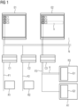
- FIG 1 shows schematically an automation system.
- this is a building automation system with heating, ventilation and/or air conditioning functionality. If necessary, other functionalities such as lighting functionalities are also integrated.
- the automation system can also be a control or regulation system of an industrial plant.
- Such an automation system typically has several control devices (also called controllers) with control or regulation functionality.
- the automation system has the control devices C1, C2 and C3.
- Each of these control devices C1 to C3 can be a so-called room controller, which takes over the control or regulation in a respective room.
- three rooms R1, R2 and R3 are indicated.
- the number of the three control devices C1 to C3 is just as arbitrary as the number of rooms R1 to R3. In any case, it makes sense to have at least two control devices so that a choice can be made between them. However, assigning these control devices to rooms is only optional.
- each control unit C1 to C3 is on at least a respective fieldbus F1, F2 and F3 is connected.
- a control device can be connected to several fieldbuses at the same time (e.g. PL-Link, DALI and Modbus). In FIG 1 For the sake of clarity, only one fieldbus is shown per control device.
- Each control device C1 to C3 controls one or more field devices G1, G2 via the respective fieldbus F1 to F3 or the respective fieldbuses (for example KNX, Modebus, LON).
- room R1 contains one or more field devices (in FIG 1 not shown), which are connected to the control unit C1 via the fieldbus F1.
- one or more field devices can be provided in the room R2 (in FIG 1 not shown), which are connected to the control unit C2 via the fieldbus F2.
- the field device G1, which is connected to the control device C3 via the fieldbus F3, was drawn somewhat more specifically in the room R3.
- another field device G2, which belongs to a system A1 is connected to the control device C3.
- the field devices G1 and G2, but also those in the other rooms or systems, are connected directly to the associated control devices C1 to C3 via the respective fieldbus F1 to F3.
- the field devices G1, G2 usually have a so-called “service pin” or a programming button on the display or control panel.
- the respective field device G1, G2 registers, for example, an actuation of the service pin or the programming button.
- the field device can also have a different interface for user interaction.
- a field device can also have a microphone with corresponding speech processing. This means that voice input is possible for the field device.
- the field device can can also be operated via a remote control. In this case, the field device in question would have a remote control interface. Any other interfaces for user interactions are conceivable. In the following, however, the service pin or the programming button will always be mentioned as representative of other interfaces for user interaction.
- Voice input on the end device is also very useful because it allows commands to be transmitted to the field device via the data network.
- the respective field device When the service pin or the programming button/program button is pressed, the respective field device generates a control signal, which is sent to the corresponding control device C1 to C3. This control signal from the field device is received by the respective control device (e.g. room controller). The transmission takes place according to the respective fieldbus protocol.
- the respective control device e.g. room controller
- Each control device C1 to C3 is also connected to a common data network N.
- This data network N can be a BACnet IP network.
- This data network N enables, for example, standardized data transmission in accordance with the Internet Protocol.
- a terminal E1 or E2 with a corresponding data interface can be connected to such a, preferably standardized, data network.
- FIG 1 Two terminal devices E1 and E2 are shown in order to be able to display the different screen displays. Typically, however, only one end device is connected to the data network as a commissioning tool.
- Such a terminal E1 or E2 can also be referred to as a “tool client”. With it it is possible to commission or maintain the respective control devices C1 to C3 and/or the field devices G1, G2, but possibly also the entire automation system.
- a device can be a BACnet engineering tool or a mobile app.
- the terminal E1, E2 may therefore be implemented as software and/or hardware.
- the respective control device C1 to C3 converts the control signal a, which comes from the field device G1 triggered by a user interaction, into an identification message i.
- This identification message i is sent, for example, into the data network N as an “identification broadcast message”. This means that every participant in the data network receives this identification message i. It is therefore triggered by a control signal a from a generally easily accessible field device G1, G2, which causes the control device to send out an identification message. The same can be achieved if such an identification message is sent directly on the control units C1 to C3, possibly via a service pin.
- the terminal E1 or E2 on the data network N has the ability to receive this identification message i and to automatically identify the control device in the terminal E1, E2 based on the data content of this message. If necessary, a corresponding display is initiated on the terminal device.
- a display can, for example, be a highlight h on the screen of the terminal E1 or B2, with which a representative "C1", “C2", “C3”, etc. is visually highlighted or identified.
- the highlighting h can be done by a specific color or a specific brightness.
- Other optical means are also conceivable, such as flashing, magnifying and the like.
- the service technician now sees on the terminal the control device C1 to C3 belonging to a room R1 to R3 or terminal device G1, G2 selected by the highlighting h. This means that the service technician knows which control unit sent the identification message. This means he can start straight away with his installation/service tasks.
- FIG 2 gives a simplified example of a method according to the invention using blocks. Individual process steps may be optional.
- a service technician is faced with the task of commissioning or maintaining an automation system in a room or part of it.
- its terminal E2 is connected to a data network N wirelessly or by wire, as is the control device C3 that is to be put into operation or maintained.
- the service technician has access to a field device G1 in the relevant room R3, which is directly connected to the control device C3.
- the service technician does not know which of the several control devices C1 to C3 is connected to the field device G1. He will be shown on the screen of the device (compare FIG 1 : End device E1) only the three control devices C1 to C3 are displayed.
- step S1 a triggering (an action) of a field device to generate a control signal through a user interaction.
- the service technician presses the service pin on the field device G1, and the field device G1 then generates the control signal a.
- step S2 the control signal a is transmitted to one of the several control devices C3 via a fieldbus F3 in accordance with a fieldbus protocol. This control signal a is received by the control unit C3.
- an identification message is generated in accordance with a network protocol different from the fieldbus protocol by one of the several control devices C3 on the basis of the control signal a.
- a signal conversion from one protocol to another protocol takes place in the addressed control device C3.
- the control unit caused by the control signal to place identification information in the form of an identification message in the data network N, preferably as a broadcast message.
- the identification message therefore contains information about the identity of one of the several control devices C3. If necessary, this identification message is enriched with further information about the identity of the triggering field device.
- a step S4 the identification message is transmitted via the data network N to a terminal E1 or E2 (In FIG 1
- a terminal E1 or E2 In FIG 1
- two terminal devices E1 and E2 are shown in order to reproduce the different image contents before determining the control device and after determining the control device.
- step S5 one of the several control devices C3 is identified by the terminal based on the identification message.
- the terminal E2 highlights the representative "C3" of the control device C3 by highlighting h (color, brightness, etc.) compared to the representatives "C1" and "C2" of the other two control devices C1, C2.
- the identification numbers are stored in advance in the terminal E2 together with the representatives of the respective control devices.
- the service technician can quickly and safely identify or locate the correct controller for the room and begin a test straight away.
- the method or automation system can also be used for localization, so that beacons or other positioning devices (e.g. GPS) can be dispensed with and it is not necessary to use additional components for location to install.
- the invention also significantly simplifies service operations during ongoing operation, because the automatic identification of the correct control device via the service pin from the field device means that current measurement data or status data, for example, can also be read directly from the field device.
- the time-consuming creation of labels on the devices to describe the position may be eliminated, thereby reducing the risk of mix-ups.
- the execution of service work becomes significantly faster, more reliable and more traceable.
Landscapes
- Engineering & Computer Science (AREA)
- General Engineering & Computer Science (AREA)
- Manufacturing & Machinery (AREA)
- Quality & Reliability (AREA)
- Physics & Mathematics (AREA)
- General Physics & Mathematics (AREA)
- Automation & Control Theory (AREA)
- Selective Calling Equipment (AREA)
Claims (13)
- Procédé pour déterminer l'un d'une pluralité de dispositifs de commande (C1, C2, C3) dans un réseau de données (N) d'un système d'automatisation consistant à- déclencher une action d'un dispositif de terrain (G1, G2) pour générer un signal de commande (a) par une interaction avec l'utilisateur,- transmettre le signal de commande (a) à l'un de la pluralité de dispositifs de commande (C1, C2, C3) via un bus de terrain (F1, F2, F3) conformément à un protocole de bus de terrain,- générer un message d'identification (i) selon un protocole de réseau différent du protocole de bus de terrain par l'un de la pluralité de dispositifs de commande (C1, C2, C3) sur la base du signal de commande (a), dans lequel- le message d'identification (i) comprend une information concernant l'identité de l'un de la pluralité de dispositifs de commande (C1, C2, C3),- transmettre le message d'identification (i) à un terminal (E1, E2) via le réseau de données (N), et- identifier l'un de la pluralité de dispositifs de commande (C1, C2, C3) par le terminal (E1, E1) à l'aide du message d'identification (i),caractérisé en ce que le message d'identification du dispositif de commande est déclenché indirectement par l'intermédiaire du dispositif de terrain,le message d'identification étant indépendant d'une spécification du bus de terrain.
- Procédé selon la revendication 1, dans lequel le bus de terrain (F1, F2, F3) est un bus KNX, un bus Modbus, un bus EIB, un bus EHS, un bus LON ou est réalisé avec un réseau sans fil, et le protocole de bus de terrain est spécifié en conséquence.
- Procédé selon la revendication 1 ou 2, dans lequel le réseau de données (N) est un réseau basé sur le protocole Internet.
- Procédé selon l'une des revendications précédentes, dans lequel le message d'identification (i) est un message de diffusion à tous les abonnés du réseau de données (N).
- Procédé selon l'une des revendications précédentes, dans lequel le terminal (E1, E2) est connecté sans fil au réseau de données (N).
- Procédé selon l'une des revendications précédentes, qui est mis en œuvre dans le cadre d'une mise en service ou d'une opération de maintenance du dispositif de terrain (G1, G2), de l'un de la pluralité de dispositifs de commande (C1, C2, C3) ou de l'ensemble du système d'automatisation.
- Procédé selon l'une quelconque des revendications précédentes, dans lequel l'identification de l'un de la pluralité de dispositifs de commande (C1, C2, C3) comprend une reconnaissance optique d'une représentation visuelle de l'un de la pluralité de dispositifs de commande (C1, C2, C3) sur le terminal (E1, E2).
- Procédé selon l'une des revendications précédentes, dans lequel, avec le signal de commande, des données de mesure ou des données d'état sont également transmises par le dispositif de terrain (G1, G2) à l'un de la pluralité de dispositifs de commande (C1, C2, C3).
- Système d'automatisation présentant- plusieurs dispositifs de commande (C1, C2, C3),- un terminal (E1, E2),- un réseau de données (N) auquel sont reliés la pluralité de dispositifs de commande (C1, C2, C3) et le terminal (E1, E2),- un dispositif de terrain (G1, G2), avec lequel un signal de commande (a) peut être généré par déclenchement d'une action du dispositif de terrain au moyen d'une interaction de l'utilisateur,- un bus de terrain (F1, F2, F3) avec lequel le signal de commande (a) peut être transmis à l'un de la pluralité de dispositifs de commande (C1, C2, C3) selon un protocole de bus de terrain, dans lequel- par l'un de la pluralité de dispositifs de commande (C1, C2, C3), un message d'identification (i) peut être généré conformément à un protocole de réseau différent du protocole de bus de terrain sur la base du signal de commande (a),- le message d'identification (i) comprend une information concernant l'identité de l'un de la pluralité de dispositifs de commande (C1, C2, C3),- le message d'identification peut être transmis de l'un de la pluralité de dispositifs de commande (C1, C2, C3) au terminal (E1, E2) via le réseau de données (N) et- par le terminal (E1, E2), l'un de la pluralité de dispositifs de commande (C1, C2, C3) est identifiable à l'aide du message d'identification (i),caractérisé en ce que le message d'identification du dispositif de commande peut être déclenché indirectement par l'intermédiaire du dispositif de terrain, etdans lequel le message d'identification est indépendant d'une spécification du bus de terrain.
- Système d'automatisation selon la revendication 9, dans lequel l'un de la pluralité de dispositifs de commande (C1, C2, C3) est le seul dispositif de commande auquel le dispositif de terrain (G1, G2) est connecté.
- Système d'automatisation selon la revendication 9 ou 10, dans lequel le dispositif de terrain (G1, G2) possède une touche de service ou une touche de programmation pour l'interaction avec l'utilisateur, avec laquelle le déclenchement du signal de commande (a) peut être exécuté manuellement.
- Système d'automatisation selon la revendication 9 ou 10, dans lequel le dispositif de terrain (G1, G2) possède un dispositif d'entrée vocale pour l'interaction avec l'utilisateur, avec lequel le déclenchement du signal de commande (a) peut être exécuté verbalement.
- Système d'automatisation selon l'une des revendications 9 à 12, dans lequel le terminal (E1, E2) est un PC, un smartphone, une tablette ou un ordinateur portable.
Applications Claiming Priority (2)
| Application Number | Priority Date | Filing Date | Title |
|---|---|---|---|
| DE102018214930.5A DE102018214930A1 (de) | 2018-09-03 | 2018-09-03 | Identifizieren von Steuergeräten in Automatisierungssystemen |
| PCT/EP2019/072861 WO2020048825A1 (fr) | 2018-09-03 | 2019-08-27 | Identification de contrôleurs dans des systèmes d'automatisation |
Publications (2)
| Publication Number | Publication Date |
|---|---|
| EP3847516A1 EP3847516A1 (fr) | 2021-07-14 |
| EP3847516B1 true EP3847516B1 (fr) | 2023-11-15 |
Family
ID=67956706
Family Applications (1)
| Application Number | Title | Priority Date | Filing Date |
|---|---|---|---|
| EP19769033.2A Active EP3847516B1 (fr) | 2018-09-03 | 2019-08-27 | Identification des contrôleurs dans un système d'automatisation |
Country Status (4)
| Country | Link |
|---|---|
| EP (1) | EP3847516B1 (fr) |
| DE (1) | DE102018214930A1 (fr) |
| ES (1) | ES2971591T3 (fr) |
| WO (1) | WO2020048825A1 (fr) |
Family Cites Families (7)
| Publication number | Priority date | Publication date | Assignee | Title |
|---|---|---|---|---|
| EP1249747A1 (fr) * | 2001-04-09 | 2002-10-16 | Patria Ailon | Système de contrôle et procédé de commande de processus |
| DE102004052075A1 (de) * | 2004-10-26 | 2006-04-27 | Jungheinrich Ag | Knoten für ein Bus-Netzwerk, Bus-Netzwerk und Verfahren zum Konfigurieren des Netzwerks |
| US10678225B2 (en) * | 2013-03-04 | 2020-06-09 | Fisher-Rosemount Systems, Inc. | Data analytic services for distributed industrial performance monitoring |
| US10282676B2 (en) * | 2014-10-06 | 2019-05-07 | Fisher-Rosemount Systems, Inc. | Automatic signal processing-based learning in a process plant |
| GB2513706B (en) * | 2013-03-15 | 2020-09-23 | Fisher Rosemount Systems Inc | Method for initiating or resuming a mobile control session in a process plant |
| DE102014001462B4 (de) * | 2014-02-05 | 2021-02-04 | Festo Se & Co. Kg | Feldbusmodul, Maschinensteuerung und Verfahren zur Parametrierung eines, insbesondere sicherheitsgerichteten, Feldbusmoduls |
| DE102016216921A1 (de) | 2016-09-07 | 2018-03-08 | Siemens Schweiz Ag | Verfahren und Anordnung zur Inbetriebnahme von Regel- und Steuergeräten für eine Gebäudeautomatisierung |
-
2018
- 2018-09-03 DE DE102018214930.5A patent/DE102018214930A1/de active Pending
-
2019
- 2019-08-27 WO PCT/EP2019/072861 patent/WO2020048825A1/fr unknown
- 2019-08-27 ES ES19769033T patent/ES2971591T3/es active Active
- 2019-08-27 EP EP19769033.2A patent/EP3847516B1/fr active Active
Also Published As
| Publication number | Publication date |
|---|---|
| EP3847516A1 (fr) | 2021-07-14 |
| DE102018214930A1 (de) | 2020-03-05 |
| WO2020048825A1 (fr) | 2020-03-12 |
| ES2971591T3 (es) | 2024-06-06 |
Similar Documents
| Publication | Publication Date | Title |
|---|---|---|
| EP2453326B1 (fr) | Procédé et système destinés à la commande d'une machine issue de la technique d'automatisation | |
| EP1710647A2 (fr) | Intégration d'appareils de terrain dans un système d'automatisation | |
| EP3293588A1 (fr) | Procédé d'approvisionnement de composants d'automatisation de pièces d'un système domotique | |
| EP3282329A1 (fr) | Procédé et système d'utilisation télécommandée d'un dispositif de terrain pour l'automatisation de processus | |
| DE102007037247A1 (de) | System und Verfahren zur Instandhaltungsunterstützung | |
| EP3285995A1 (fr) | Machine de production de comprimés équipée d'un dispositif d'exécution d'une application de tableau de bord | |
| EP3847516B1 (fr) | Identification des contrôleurs dans un système d'automatisation | |
| EP4123396A1 (fr) | Technique destinée à la réalisation d'une visualisation pour une installation technique d'automatisation dotée d'une commande à mémoire programmable | |
| DE102016123599A1 (de) | Robotersteuerung mit Funktion zur Kommunikation mit einer speicherprogrammierbaren Steuerung und Kommunikationssystem | |
| EP3088975B1 (fr) | Parametrage d'appareil se rapportant a un canal | |
| EP2180388B1 (fr) | Procédé de projection d'une installation électrique programmable orientée vers le bus | |
| EP2839348B1 (fr) | Procédé de configuration d'un système d'automatisme | |
| DE102004051834B4 (de) | Prüfgerät und Prüfverfahren für programmierbare Elektroinstallationen, sowie entsprechendes Computerprogramm und entsprechendes computerlesbares Speichermedium | |
| EP4138052B1 (fr) | Procédé de préparation d'une mise en service d'un appareil de commande pour dispositifs d'accès, système d'accès et produit-programme informatique | |
| EP1134864A1 (fr) | Procédé et dispositif graphique pour la planification des composants électriques dans un bâtiment | |
| WO2024068742A1 (fr) | Procédé d'installation assistée par ordinateur de composants spatialement décentralisés d'une machine | |
| DE102016204395B4 (de) | Toolfreier Gerätetausch von Busgeräten | |
| EP4345554A1 (fr) | Procédé d'installation assistée par ordinateur de composants électriques d'une machine agencés de manière décentralisée dans l'espace | |
| DE102015116399A1 (de) | Verfahren zur Verwaltung und Konfiguration von Feldgeräten einer Automatisierungsanlage | |
| DE102015218029B4 (de) | Verfahren zum Betreiben eines Busgerätes | |
| EP2028575B1 (fr) | Procédé de lecture et/ou d'écriture de propriétés ou de paramètres d'un appareil d'installation connecté à un système de bus | |
| WO2024099820A1 (fr) | Procédé de vérification assistée par ordinateur d'un élément d'installation pour un environnement d'installation | |
| WO2024068816A1 (fr) | Procédé de fonctionnement d'un module de connexion | |
| DE102014007383A1 (de) | Einrichtung zur Verwaltung und Konfiguration von Feldgeräten einer Automatisierungsanlage | |
| EP4141459A1 (fr) | Instrument d'exécution autonome de séquences d'essai selon la norme jtag |
Legal Events
| Date | Code | Title | Description |
|---|---|---|---|
| STAA | Information on the status of an ep patent application or granted ep patent |
Free format text: STATUS: UNKNOWN |
|
| STAA | Information on the status of an ep patent application or granted ep patent |
Free format text: STATUS: THE INTERNATIONAL PUBLICATION HAS BEEN MADE |
|
| STAA | Information on the status of an ep patent application or granted ep patent |
Free format text: STATUS: THE INTERNATIONAL PUBLICATION HAS BEEN MADE |
|
| PUAI | Public reference made under article 153(3) epc to a published international application that has entered the european phase |
Free format text: ORIGINAL CODE: 0009012 |
|
| STAA | Information on the status of an ep patent application or granted ep patent |
Free format text: STATUS: REQUEST FOR EXAMINATION WAS MADE |
|
| 17P | Request for examination filed |
Effective date: 20210126 |
|
| AK | Designated contracting states |
Kind code of ref document: A1 Designated state(s): AL AT BE BG CH CY CZ DE DK EE ES FI FR GB GR HR HU IE IS IT LI LT LU LV MC MK MT NL NO PL PT RO RS SE SI SK SM TR |
|
| DAV | Request for validation of the european patent (deleted) | ||
| DAX | Request for extension of the european patent (deleted) | ||
| GRAP | Despatch of communication of intention to grant a patent |
Free format text: ORIGINAL CODE: EPIDOSNIGR1 |
|
| STAA | Information on the status of an ep patent application or granted ep patent |
Free format text: STATUS: GRANT OF PATENT IS INTENDED |
|
| INTG | Intention to grant announced |
Effective date: 20230724 |
|
| GRAS | Grant fee paid |
Free format text: ORIGINAL CODE: EPIDOSNIGR3 |
|
| GRAA | (expected) grant |
Free format text: ORIGINAL CODE: 0009210 |
|
| STAA | Information on the status of an ep patent application or granted ep patent |
Free format text: STATUS: THE PATENT HAS BEEN GRANTED |
|
| AK | Designated contracting states |
Kind code of ref document: B1 Designated state(s): AL AT BE BG CH CY CZ DE DK EE ES FI FR GB GR HR HU IE IS IT LI LT LU LV MC MK MT NL NO PL PT RO RS SE SI SK SM TR |
|
| REG | Reference to a national code |
Ref country code: CH Ref legal event code: EP Ref country code: GB Ref legal event code: FG4D Free format text: NOT ENGLISH |
|
| REG | Reference to a national code |
Ref country code: DE Ref legal event code: R096 Ref document number: 502019009937 Country of ref document: DE |
|
| REG | Reference to a national code |
Ref country code: IE Ref legal event code: FG4D Free format text: LANGUAGE OF EP DOCUMENT: GERMAN |
|
| P01 | Opt-out of the competence of the unified patent court (upc) registered |
Effective date: 20231120 |
|
| REG | Reference to a national code |
Ref country code: NL Ref legal event code: FP |
|
| REG | Reference to a national code |
Ref country code: LT Ref legal event code: MG9D |
|
| PG25 | Lapsed in a contracting state [announced via postgrant information from national office to epo] |
Ref country code: GR Free format text: LAPSE BECAUSE OF FAILURE TO SUBMIT A TRANSLATION OF THE DESCRIPTION OR TO PAY THE FEE WITHIN THE PRESCRIBED TIME-LIMIT Effective date: 20240216 |
|
| PG25 | Lapsed in a contracting state [announced via postgrant information from national office to epo] |
Ref country code: IS Free format text: LAPSE BECAUSE OF FAILURE TO SUBMIT A TRANSLATION OF THE DESCRIPTION OR TO PAY THE FEE WITHIN THE PRESCRIBED TIME-LIMIT Effective date: 20240315 |
|
| PG25 | Lapsed in a contracting state [announced via postgrant information from national office to epo] |
Ref country code: LT Free format text: LAPSE BECAUSE OF FAILURE TO SUBMIT A TRANSLATION OF THE DESCRIPTION OR TO PAY THE FEE WITHIN THE PRESCRIBED TIME-LIMIT Effective date: 20231115 |
|
| PG25 | Lapsed in a contracting state [announced via postgrant information from national office to epo] |
Ref country code: LT Free format text: LAPSE BECAUSE OF FAILURE TO SUBMIT A TRANSLATION OF THE DESCRIPTION OR TO PAY THE FEE WITHIN THE PRESCRIBED TIME-LIMIT Effective date: 20231115 Ref country code: IS Free format text: LAPSE BECAUSE OF FAILURE TO SUBMIT A TRANSLATION OF THE DESCRIPTION OR TO PAY THE FEE WITHIN THE PRESCRIBED TIME-LIMIT Effective date: 20240315 Ref country code: GR Free format text: LAPSE BECAUSE OF FAILURE TO SUBMIT A TRANSLATION OF THE DESCRIPTION OR TO PAY THE FEE WITHIN THE PRESCRIBED TIME-LIMIT Effective date: 20240216 Ref country code: BG Free format text: LAPSE BECAUSE OF FAILURE TO SUBMIT A TRANSLATION OF THE DESCRIPTION OR TO PAY THE FEE WITHIN THE PRESCRIBED TIME-LIMIT Effective date: 20240215 Ref country code: PT Free format text: LAPSE BECAUSE OF FAILURE TO SUBMIT A TRANSLATION OF THE DESCRIPTION OR TO PAY THE FEE WITHIN THE PRESCRIBED TIME-LIMIT Effective date: 20240315 |
|
| PG25 | Lapsed in a contracting state [announced via postgrant information from national office to epo] |
Ref country code: SE Free format text: LAPSE BECAUSE OF FAILURE TO SUBMIT A TRANSLATION OF THE DESCRIPTION OR TO PAY THE FEE WITHIN THE PRESCRIBED TIME-LIMIT Effective date: 20231115 Ref country code: RS Free format text: LAPSE BECAUSE OF FAILURE TO SUBMIT A TRANSLATION OF THE DESCRIPTION OR TO PAY THE FEE WITHIN THE PRESCRIBED TIME-LIMIT Effective date: 20231115 Ref country code: PL Free format text: LAPSE BECAUSE OF FAILURE TO SUBMIT A TRANSLATION OF THE DESCRIPTION OR TO PAY THE FEE WITHIN THE PRESCRIBED TIME-LIMIT Effective date: 20231115 Ref country code: NO Free format text: LAPSE BECAUSE OF FAILURE TO SUBMIT A TRANSLATION OF THE DESCRIPTION OR TO PAY THE FEE WITHIN THE PRESCRIBED TIME-LIMIT Effective date: 20240215 Ref country code: LV Free format text: LAPSE BECAUSE OF FAILURE TO SUBMIT A TRANSLATION OF THE DESCRIPTION OR TO PAY THE FEE WITHIN THE PRESCRIBED TIME-LIMIT Effective date: 20231115 Ref country code: HR Free format text: LAPSE BECAUSE OF FAILURE TO SUBMIT A TRANSLATION OF THE DESCRIPTION OR TO PAY THE FEE WITHIN THE PRESCRIBED TIME-LIMIT Effective date: 20231115 |
|
| REG | Reference to a national code |
Ref country code: ES Ref legal event code: FG2A Ref document number: 2971591 Country of ref document: ES Kind code of ref document: T3 Effective date: 20240606 |
|
| PG25 | Lapsed in a contracting state [announced via postgrant information from national office to epo] |
Ref country code: DK Free format text: LAPSE BECAUSE OF FAILURE TO SUBMIT A TRANSLATION OF THE DESCRIPTION OR TO PAY THE FEE WITHIN THE PRESCRIBED TIME-LIMIT Effective date: 20231115 |
|
| PG25 | Lapsed in a contracting state [announced via postgrant information from national office to epo] |
Ref country code: CZ Free format text: LAPSE BECAUSE OF FAILURE TO SUBMIT A TRANSLATION OF THE DESCRIPTION OR TO PAY THE FEE WITHIN THE PRESCRIBED TIME-LIMIT Effective date: 20231115 |
|
| PG25 | Lapsed in a contracting state [announced via postgrant information from national office to epo] |
Ref country code: SK Free format text: LAPSE BECAUSE OF FAILURE TO SUBMIT A TRANSLATION OF THE DESCRIPTION OR TO PAY THE FEE WITHIN THE PRESCRIBED TIME-LIMIT Effective date: 20231115 |
|
| PG25 | Lapsed in a contracting state [announced via postgrant information from national office to epo] |
Ref country code: SM Free format text: LAPSE BECAUSE OF FAILURE TO SUBMIT A TRANSLATION OF THE DESCRIPTION OR TO PAY THE FEE WITHIN THE PRESCRIBED TIME-LIMIT Effective date: 20231115 Ref country code: SK Free format text: LAPSE BECAUSE OF FAILURE TO SUBMIT A TRANSLATION OF THE DESCRIPTION OR TO PAY THE FEE WITHIN THE PRESCRIBED TIME-LIMIT Effective date: 20231115 Ref country code: RO Free format text: LAPSE BECAUSE OF FAILURE TO SUBMIT A TRANSLATION OF THE DESCRIPTION OR TO PAY THE FEE WITHIN THE PRESCRIBED TIME-LIMIT Effective date: 20231115 Ref country code: EE Free format text: LAPSE BECAUSE OF FAILURE TO SUBMIT A TRANSLATION OF THE DESCRIPTION OR TO PAY THE FEE WITHIN THE PRESCRIBED TIME-LIMIT Effective date: 20231115 Ref country code: DK Free format text: LAPSE BECAUSE OF FAILURE TO SUBMIT A TRANSLATION OF THE DESCRIPTION OR TO PAY THE FEE WITHIN THE PRESCRIBED TIME-LIMIT Effective date: 20231115 Ref country code: CZ Free format text: LAPSE BECAUSE OF FAILURE TO SUBMIT A TRANSLATION OF THE DESCRIPTION OR TO PAY THE FEE WITHIN THE PRESCRIBED TIME-LIMIT Effective date: 20231115 |
|
| PLBE | No opposition filed within time limit |
Free format text: ORIGINAL CODE: 0009261 |
|
| STAA | Information on the status of an ep patent application or granted ep patent |
Free format text: STATUS: NO OPPOSITION FILED WITHIN TIME LIMIT |
|
| PGFP | Annual fee paid to national office [announced via postgrant information from national office to epo] |
Ref country code: NL Payment date: 20240805 Year of fee payment: 6 |