EP3847516B1 - Control device identification in an automated system - Google Patents
Control device identification in an automated system Download PDFInfo
- Publication number
- EP3847516B1 EP3847516B1 EP19769033.2A EP19769033A EP3847516B1 EP 3847516 B1 EP3847516 B1 EP 3847516B1 EP 19769033 A EP19769033 A EP 19769033A EP 3847516 B1 EP3847516 B1 EP 3847516B1
- Authority
- EP
- European Patent Office
- Prior art keywords
- control devices
- identification message
- several control
- field device
- terminal
- Prior art date
- Legal status (The legal status is an assumption and is not a legal conclusion. Google has not performed a legal analysis and makes no representation as to the accuracy of the status listed.)
- Active
Links
- 238000000034 method Methods 0.000 claims description 23
- 230000003993 interaction Effects 0.000 claims description 13
- 230000001960 triggered effect Effects 0.000 claims description 6
- 238000005259 measurement Methods 0.000 claims description 3
- 230000000007 visual effect Effects 0.000 claims 1
- 238000009434 installation Methods 0.000 description 8
- 238000012360 testing method Methods 0.000 description 4
- 230000033228 biological regulation Effects 0.000 description 3
- 230000005540 biological transmission Effects 0.000 description 3
- 238000004891 communication Methods 0.000 description 3
- 230000000694 effects Effects 0.000 description 3
- 238000010295 mobile communication Methods 0.000 description 3
- 230000002093 peripheral effect Effects 0.000 description 3
- 238000004378 air conditioning Methods 0.000 description 2
- 238000006243 chemical reaction Methods 0.000 description 2
- 238000010586 diagram Methods 0.000 description 2
- 238000010438 heat treatment Methods 0.000 description 2
- 238000009423 ventilation Methods 0.000 description 2
- 210000000988 bone and bone Anatomy 0.000 description 1
- 238000010276 construction Methods 0.000 description 1
- 238000013461 design Methods 0.000 description 1
- 238000011161 development Methods 0.000 description 1
- 230000018109 developmental process Effects 0.000 description 1
- 238000003745 diagnosis Methods 0.000 description 1
- 238000005516 engineering process Methods 0.000 description 1
- 230000004807 localization Effects 0.000 description 1
- 238000012423 maintenance Methods 0.000 description 1
- 230000007257 malfunction Effects 0.000 description 1
- 230000003287 optical effect Effects 0.000 description 1
- 238000005457 optimization Methods 0.000 description 1
- 238000012545 processing Methods 0.000 description 1
- 230000001105 regulatory effect Effects 0.000 description 1
- 230000008054 signal transmission Effects 0.000 description 1
- 230000011664 signaling Effects 0.000 description 1
- 238000012549 training Methods 0.000 description 1
Images

Classifications
-
- G—PHYSICS
- G05—CONTROLLING; REGULATING
- G05B—CONTROL OR REGULATING SYSTEMS IN GENERAL; FUNCTIONAL ELEMENTS OF SUCH SYSTEMS; MONITORING OR TESTING ARRANGEMENTS FOR SUCH SYSTEMS OR ELEMENTS
- G05B19/00—Programme-control systems
- G05B19/02—Programme-control systems electric
- G05B19/418—Total factory control, i.e. centrally controlling a plurality of machines, e.g. direct or distributed numerical control [DNC], flexible manufacturing systems [FMS], integrated manufacturing systems [IMS] or computer integrated manufacturing [CIM]
-
- G—PHYSICS
- G05—CONTROLLING; REGULATING
- G05B—CONTROL OR REGULATING SYSTEMS IN GENERAL; FUNCTIONAL ELEMENTS OF SUCH SYSTEMS; MONITORING OR TESTING ARRANGEMENTS FOR SUCH SYSTEMS OR ELEMENTS
- G05B19/00—Programme-control systems
- G05B19/02—Programme-control systems electric
- G05B19/04—Programme control other than numerical control, i.e. in sequence controllers or logic controllers
- G05B19/042—Programme control other than numerical control, i.e. in sequence controllers or logic controllers using digital processors
-
- G—PHYSICS
- G05—CONTROLLING; REGULATING
- G05B—CONTROL OR REGULATING SYSTEMS IN GENERAL; FUNCTIONAL ELEMENTS OF SUCH SYSTEMS; MONITORING OR TESTING ARRANGEMENTS FOR SUCH SYSTEMS OR ELEMENTS
- G05B19/00—Programme-control systems
- G05B19/02—Programme-control systems electric
- G05B19/418—Total factory control, i.e. centrally controlling a plurality of machines, e.g. direct or distributed numerical control [DNC], flexible manufacturing systems [FMS], integrated manufacturing systems [IMS] or computer integrated manufacturing [CIM]
- G05B19/4185—Total factory control, i.e. centrally controlling a plurality of machines, e.g. direct or distributed numerical control [DNC], flexible manufacturing systems [FMS], integrated manufacturing systems [IMS] or computer integrated manufacturing [CIM] characterised by the network communication
-
- Y—GENERAL TAGGING OF NEW TECHNOLOGICAL DEVELOPMENTS; GENERAL TAGGING OF CROSS-SECTIONAL TECHNOLOGIES SPANNING OVER SEVERAL SECTIONS OF THE IPC; TECHNICAL SUBJECTS COVERED BY FORMER USPC CROSS-REFERENCE ART COLLECTIONS [XRACs] AND DIGESTS
- Y02—TECHNOLOGIES OR APPLICATIONS FOR MITIGATION OR ADAPTATION AGAINST CLIMATE CHANGE
- Y02P—CLIMATE CHANGE MITIGATION TECHNOLOGIES IN THE PRODUCTION OR PROCESSING OF GOODS
- Y02P90/00—Enabling technologies with a potential contribution to greenhouse gas [GHG] emissions mitigation
- Y02P90/02—Total factory control, e.g. smart factories, flexible manufacturing systems [FMS] or integrated manufacturing systems [IMS]
Definitions
- the present invention relates to a method for determining one of several control devices in a data network of an automation system.
- the present invention relates to an automation system with a plurality of control devices, a terminal device, a data network to which the control devices and the terminal device are connected, a field device and a fieldbus to which the field device is connected to one of the control devices.
- Commissioning but also service activities in general for (building) automation systems, for example for heating, ventilation or air conditioning functionality (HVAC), requires a clear identification of the control and control devices or controllers (hereinafter summarized as control devices), for example in a commissioning tool of a (room) automation system so that, for example, the necessary commissioning tests can be carried out with the correct control device.
- a commissioning tool is a device or an application that can be used to carry out commissioning.
- Such a commissioning tool can be, for example, a specially designed end device, but also a smartphone, a tablet, a PC and the like, as well as a software application in a service or commissioning environment.
- Commissioning refers in particular to the setting of a system, system or machine. This means, in particular, measures and actions (e.g. configuration, parameterization, optimization and testing) that are necessary to make a machine or system operational or ready for use. Commissioning includes measures and activities that occur after the hardware has been installed, particularly the field devices and controllers or after installing the software to set up and test the product/system.
- control devices or controllers for room, building or other automation systems are often installed in poorly accessible locations. For example, they are installed in false ceilings, in window panels or in a false floor and are not or barely visible or accessible from the outside.
- One or more field devices that provide respective functionalities are usually connected to a control device.
- a field device refers in particular to sensors, actuators and operating devices. States of the field devices are represented in the control device (e.g. controller) by corresponding data sets or data points.
- the actuators are advantageously equipped with additional sensors in order to determine the status or feedback from the process in the controller and in the instructions and to support diagnosis in the event of malfunction.
- a commissioning tool or service tool (hereinafter referred to as a terminal device) and the control device usually takes place via a building network or data network (back bone), which is preferably based on the Internet protocol (IP).
- IP Internet protocol
- the commissioning tool can, for example, send a so-called “wink command” to a room controller via the IP BACnet network.
- the room controller can signal, for example by flashing an LED or an acoustic signal.
- the service technician may be difficult for the service technician to see or perceive this flashing or signal tone.
- the commissioning tool can establish a connection to the room controller using a unique controller serial number.
- the serial number must be known and in the Commissioning tool can be entered. However, the serial number visible on the controller often cannot be used for identification due to the hidden assembly.
- the commissioning tool can also be physically connected directly to the room controller on site (for example with a USB cable). This means that the room controller can be clearly identified. This procedure also depends on the installation location and the accessibility of the room controller.
- the commissioning tool can be physically connected to the room controller indirectly via a room or field device (peripheral device).
- the field device is usually easily accessible and clearly assigned to the room controller.
- the field device must be specifically set up for this function and this procedure is often not possible with third-party field devices.
- control and control devices are used to regulate or control field devices for building automation.
- a communication connection is created between the control and control device and a user's mobile communication terminal.
- the mobile communication terminal is set up to query data points of the control and control device via the communication connection and to check their respective status.
- a data point represents the state of a parameter of a field device.
- the mobile communication terminal is further designed to transmit the status of the data points to a central location via a further communication connection.
- the object of the present invention is to simplify the handling of control devices in an automation system.
- control devices representing control and/or regulating devices.
- the several control devices are networked via a data network for signaling and data technology.
- a specific one is often necessary to clearly identify several control devices.
- an identification message from the control device is triggered indirectly via a field device.
- the field device can be operated manually and through this manual operation the field device generates the corresponding control signal.
- This control signal is transmitted to the respective (assigned) control device via at least one fieldbus. This signal transmission takes place according to a fieldbus protocol. If necessary, a field device-specific control signal is transmitted to the respective control device in accordance with the fieldbus protocol.
- the control unit receives this control signal and uses it to generate an identification message.
- This identification message is created according to a network protocol that is different from the fieldbus protocol. A protocol conversion therefore takes place in the control unit.
- the identification message contains information about the identity of the control device generating the identification message. This information may be a unique identifier in electrical form.
- the identification message is then transmitted via the data network to a terminal device, for example a commissioning tool. This transmission of the identification message is independent of the specification of the fieldbus.
- the terminal can identify the specific control device that was controlled by the field device based on the identification message or the identity information contained therein.
- the identification of the control device is initiated or triggered by the field device. Therefore, it is not necessary to be able to reach or at least see the control unit manually.
- the commissioning of the control unit or the automation system as well as their maintenance can be significantly simplified.
- the fieldbus is a KNX bus, a Modbus, an EIB bus, an EHS bus or a LON bus, or the fieldbus is implemented with a wireless network (e.g. ZigBee), and that Fieldbus protocol is specified accordingly.
- a wireless network e.g. ZigBee
- Such bus systems are widespread and can be used conveniently for building installations. There are therefore corresponding commissioning and service advantages, especially for building installation systems.
- the data network is a network based on the Internet Protocol (IP).
- IP Internet Protocol
- the identification message is a broadcast message that is sent to all participants in the data network.
- the identification message is therefore distributed throughout the entire data network and is in principle accessible to every device. Such a broadcast message can thus ensure that the identification information actually reaches the terminal device integrated into the data network.
- the terminal device is connected wirelessly to the data network.
- a WLAN-compatible or Bluetooth-compatible terminal device can be used for commissioning or servicing the automation system.
- the service technician for example, is much more flexible when it comes to commissioning, servicing or even just identifying the respective control device.
- the method is carried out as part of a commissioning or service measure of the field device one of the several control devices or the entire automation system. If necessary, only a part of the automation system with several devices is affected by the commissioning or service.
- a specific control device is identified during commissioning or during service. This determination or identification of the specific control device can be done using the method described. After this identification, a correct commissioning function or service function can be carried out in or on the control device or in its peripherals.
- identifying the one of the multiple control devices can include visually identifying a pictorial representative of the one of the multiple control devices on the terminal. For example, several control devices and possibly field devices are displayed graphically on a screen of the terminal device. According to the result of the identification, the pictorial representation or the pictorial representative of that control device is now visually identified (for example highlighted in color) that corresponds to the identified control device.
- the service technician can immediately record the identified control device and receive a wealth of information that is related to the field device (e.g. other measured variables/diagnostic information). For example, the user receives comprehensive information on the end device for their tasks (e.g. can be used to limit errors).
- measurement data or status data are also transmitted from the terminal device to one of the several control devices with the control signal.
- the control signal not only initiates the generation of the identification message in the control device, but the control signal also receives the additional functionality that specific data from the end device, such as For example, the current temperature in the case of a temperature sensor in the field device is transmitted to the control device. If necessary, a switching state or the like can also be transmitted to the control unit with the control signal.
- one of the several control devices is the only control device with which the field device is connected. This ensures that there is a clear assignment of the field device and the control device. In this way it can also be ensured that only the very specific control device is addressed for identification purposes with the field device.
- the field device has a service button or a programming button, or a key combination or key sequence with appropriate logic can be provided for user interaction, with which the triggering of the control signal can be carried out manually.
- the respective keys also include switches or touch fields with which input is made by pressing or touching. In this way, safe triggering of the control signal can be guaranteed.
- the field device has a voice input device for user interaction, with which the triggering of the control signal can be carried out verbally.
- the service technician for example, does not have to make direct physical contact with the field device. Rather, it controls the field device through appropriate voice input in order to generate the control signal for the control device.
- the end device is a PC, a smartphone, a tablet or a laptop. Of course, this does not exclude other computing devices.
- the terminal device can also be a device specifically provided by the manufacturer of the automation system, which is optimized, for example, for commissioning or for service measures.
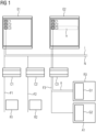
- FIG 1 shows schematically an automation system.
- this is a building automation system with heating, ventilation and/or air conditioning functionality. If necessary, other functionalities such as lighting functionalities are also integrated.
- the automation system can also be a control or regulation system of an industrial plant.
- Such an automation system typically has several control devices (also called controllers) with control or regulation functionality.
- the automation system has the control devices C1, C2 and C3.
- Each of these control devices C1 to C3 can be a so-called room controller, which takes over the control or regulation in a respective room.
- three rooms R1, R2 and R3 are indicated.
- the number of the three control devices C1 to C3 is just as arbitrary as the number of rooms R1 to R3. In any case, it makes sense to have at least two control devices so that a choice can be made between them. However, assigning these control devices to rooms is only optional.
- each control unit C1 to C3 is on at least a respective fieldbus F1, F2 and F3 is connected.
- a control device can be connected to several fieldbuses at the same time (e.g. PL-Link, DALI and Modbus). In FIG 1 For the sake of clarity, only one fieldbus is shown per control device.
- Each control device C1 to C3 controls one or more field devices G1, G2 via the respective fieldbus F1 to F3 or the respective fieldbuses (for example KNX, Modebus, LON).
- room R1 contains one or more field devices (in FIG 1 not shown), which are connected to the control unit C1 via the fieldbus F1.
- one or more field devices can be provided in the room R2 (in FIG 1 not shown), which are connected to the control unit C2 via the fieldbus F2.
- the field device G1, which is connected to the control device C3 via the fieldbus F3, was drawn somewhat more specifically in the room R3.
- another field device G2, which belongs to a system A1 is connected to the control device C3.
- the field devices G1 and G2, but also those in the other rooms or systems, are connected directly to the associated control devices C1 to C3 via the respective fieldbus F1 to F3.
- the field devices G1, G2 usually have a so-called “service pin” or a programming button on the display or control panel.
- the respective field device G1, G2 registers, for example, an actuation of the service pin or the programming button.
- the field device can also have a different interface for user interaction.
- a field device can also have a microphone with corresponding speech processing. This means that voice input is possible for the field device.
- the field device can can also be operated via a remote control. In this case, the field device in question would have a remote control interface. Any other interfaces for user interactions are conceivable. In the following, however, the service pin or the programming button will always be mentioned as representative of other interfaces for user interaction.
- Voice input on the end device is also very useful because it allows commands to be transmitted to the field device via the data network.
- the respective field device When the service pin or the programming button/program button is pressed, the respective field device generates a control signal, which is sent to the corresponding control device C1 to C3. This control signal from the field device is received by the respective control device (e.g. room controller). The transmission takes place according to the respective fieldbus protocol.
- the respective control device e.g. room controller
- Each control device C1 to C3 is also connected to a common data network N.
- This data network N can be a BACnet IP network.
- This data network N enables, for example, standardized data transmission in accordance with the Internet Protocol.
- a terminal E1 or E2 with a corresponding data interface can be connected to such a, preferably standardized, data network.
- FIG 1 Two terminal devices E1 and E2 are shown in order to be able to display the different screen displays. Typically, however, only one end device is connected to the data network as a commissioning tool.
- Such a terminal E1 or E2 can also be referred to as a “tool client”. With it it is possible to commission or maintain the respective control devices C1 to C3 and/or the field devices G1, G2, but possibly also the entire automation system.
- a device can be a BACnet engineering tool or a mobile app.
- the terminal E1, E2 may therefore be implemented as software and/or hardware.
- the respective control device C1 to C3 converts the control signal a, which comes from the field device G1 triggered by a user interaction, into an identification message i.
- This identification message i is sent, for example, into the data network N as an “identification broadcast message”. This means that every participant in the data network receives this identification message i. It is therefore triggered by a control signal a from a generally easily accessible field device G1, G2, which causes the control device to send out an identification message. The same can be achieved if such an identification message is sent directly on the control units C1 to C3, possibly via a service pin.
- the terminal E1 or E2 on the data network N has the ability to receive this identification message i and to automatically identify the control device in the terminal E1, E2 based on the data content of this message. If necessary, a corresponding display is initiated on the terminal device.
- a display can, for example, be a highlight h on the screen of the terminal E1 or B2, with which a representative "C1", “C2", “C3”, etc. is visually highlighted or identified.
- the highlighting h can be done by a specific color or a specific brightness.
- Other optical means are also conceivable, such as flashing, magnifying and the like.
- the service technician now sees on the terminal the control device C1 to C3 belonging to a room R1 to R3 or terminal device G1, G2 selected by the highlighting h. This means that the service technician knows which control unit sent the identification message. This means he can start straight away with his installation/service tasks.
- FIG 2 gives a simplified example of a method according to the invention using blocks. Individual process steps may be optional.
- a service technician is faced with the task of commissioning or maintaining an automation system in a room or part of it.
- its terminal E2 is connected to a data network N wirelessly or by wire, as is the control device C3 that is to be put into operation or maintained.
- the service technician has access to a field device G1 in the relevant room R3, which is directly connected to the control device C3.
- the service technician does not know which of the several control devices C1 to C3 is connected to the field device G1. He will be shown on the screen of the device (compare FIG 1 : End device E1) only the three control devices C1 to C3 are displayed.
- step S1 a triggering (an action) of a field device to generate a control signal through a user interaction.
- the service technician presses the service pin on the field device G1, and the field device G1 then generates the control signal a.
- step S2 the control signal a is transmitted to one of the several control devices C3 via a fieldbus F3 in accordance with a fieldbus protocol. This control signal a is received by the control unit C3.
- an identification message is generated in accordance with a network protocol different from the fieldbus protocol by one of the several control devices C3 on the basis of the control signal a.
- a signal conversion from one protocol to another protocol takes place in the addressed control device C3.
- the control unit caused by the control signal to place identification information in the form of an identification message in the data network N, preferably as a broadcast message.
- the identification message therefore contains information about the identity of one of the several control devices C3. If necessary, this identification message is enriched with further information about the identity of the triggering field device.
- a step S4 the identification message is transmitted via the data network N to a terminal E1 or E2 (In FIG 1
- a terminal E1 or E2 In FIG 1
- two terminal devices E1 and E2 are shown in order to reproduce the different image contents before determining the control device and after determining the control device.
- step S5 one of the several control devices C3 is identified by the terminal based on the identification message.
- the terminal E2 highlights the representative "C3" of the control device C3 by highlighting h (color, brightness, etc.) compared to the representatives "C1" and "C2" of the other two control devices C1, C2.
- the identification numbers are stored in advance in the terminal E2 together with the representatives of the respective control devices.
- the service technician can quickly and safely identify or locate the correct controller for the room and begin a test straight away.
- the method or automation system can also be used for localization, so that beacons or other positioning devices (e.g. GPS) can be dispensed with and it is not necessary to use additional components for location to install.
- the invention also significantly simplifies service operations during ongoing operation, because the automatic identification of the correct control device via the service pin from the field device means that current measurement data or status data, for example, can also be read directly from the field device.
- the time-consuming creation of labels on the devices to describe the position may be eliminated, thereby reducing the risk of mix-ups.
- the execution of service work becomes significantly faster, more reliable and more traceable.
Landscapes
- Engineering & Computer Science (AREA)
- General Engineering & Computer Science (AREA)
- Manufacturing & Machinery (AREA)
- Quality & Reliability (AREA)
- Physics & Mathematics (AREA)
- General Physics & Mathematics (AREA)
- Automation & Control Theory (AREA)
- Selective Calling Equipment (AREA)
Description
Die vorliegende Erfindung betrifft ein Verfahren zum Ermitteln eines von mehreren Steuergeräten in einem Datennetzwerk eines Automatisierungssystems. Darüber hinaus betrifft die vorliegende Erfindung ein Automatisierungssystem mit mehreren Steuergeräten, einem Endgerät, einem Datennetzwerk, mit dem die Steuergeräte und das Endgerät verbunden sind, einem Feldgerät und einem Feldbus, mit dem das Feldgerät mit einem der Steuergeräte verbunden ist.The present invention relates to a method for determining one of several control devices in a data network of an automation system. In addition, the present invention relates to an automation system with a plurality of control devices, a terminal device, a data network to which the control devices and the terminal device are connected, a field device and a fieldbus to which the field device is connected to one of the control devices.
Die Inbetriebnahme, aber auch Servicetätigkeiten allgemein bei (Gebäude-)Automatisierungssystemen zum Beispiel für Heizungs-, Lüftungs- oder Klimafunktionalität (HLK) erfordert eine eindeutige Identifikation der Regel- und Steuergeräte beziehungsweise Controller (nachfolgend als Steuergeräte zusammengefasst) zum Beispiel in einem Inbetriebnahme-Tool eines (Raum-) Automatisierungssystems, damit beispielsweise die notwendigen Inbetriebnahmetests mit dem korrekten Steuergerät durchgeführt werden können. Unter einem Inbetriebnahme-Tool versteht man ein Gerät beziehungsweise eine Applikation, mit deren/dessen Hilfe eine Inbetriebnahme durchgeführt werden kann. Ein solches Inbetriebnahme-Tool kann beispielsweise ein speziell dafür konzipiertes Endgerät, aber auch ein Smartphone, ein Tablet, ein PC und dergleichen, sowie eine Software-Applikation in einem Servicebeziehungsweise Inbetriebnahmeumfeld sein.Commissioning, but also service activities in general for (building) automation systems, for example for heating, ventilation or air conditioning functionality (HVAC), requires a clear identification of the control and control devices or controllers (hereinafter summarized as control devices), for example in a commissioning tool of a (room) automation system so that, for example, the necessary commissioning tests can be carried out with the correct control device. A commissioning tool is a device or an application that can be used to carry out commissioning. Such a commissioning tool can be, for example, a specially designed end device, but also a smartphone, a tablet, a PC and the like, as well as a software application in a service or commissioning environment.
Unter Inbetriebnahme wird insbesondere das Einstellen eines Systems, einer Anlage oder Maschine verstanden. Das heißt, insbesondere Maßnahmen und Handlungen (zum Beispiel Konfiguration, Parametrierung, Optimierung und Test), die notwendig sind, um eine Maschine oder Anlage betriebsbereit beziehungsweise einsatzbereit zu machen. Eine Inbetriebnahme umfasst Maßnahmen und Tätigkeiten, die nach der Montage der Hardware insbesondere der Feldgeräte und Controller beziehungsweise nach der Installation der Software zur Einrichtung und Prüfung des Produkts/Systems durchgeführt werden.Commissioning refers in particular to the setting of a system, system or machine. This means, in particular, measures and actions (e.g. configuration, parameterization, optimization and testing) that are necessary to make a machine or system operational or ready for use. Commissioning includes measures and activities that occur after the hardware has been installed, particularly the field devices and controllers or after installing the software to set up and test the product/system.
Die Steuergeräte beziehungsweise Controller für Raum-, Gebäude- oder andere Automatisationssysteme sind häufig an schlecht zugänglichen Standorten installiert. Beispielsweise werden sie in Zwischendecken, in Fensterpanelen oder in einem Zwischenboden installiert und sind von außen nicht oder kaum sichtbar beziehungsweise zugänglich. An ein Steuergerät sind in der Regel eines oder mehrere Feldgeräte angeschlossen, die jeweilige Funktionalitäten bereitstellen.The control devices or controllers for room, building or other automation systems are often installed in poorly accessible locations. For example, they are installed in false ceilings, in window panels or in a false floor and are not or barely visible or accessible from the outside. One or more field devices that provide respective functionalities are usually connected to a control device.
Unter einem Feldgerät werden insbesondere Sensoren, und Aktoren und Bediengeräte verstanden. Zustände der Feldgeräte werden im Regel- und Steuergerät (zum Beispiel Controller) durch entsprechende Datensätze beziehungsweise Datenpunkte repräsentiert. Mit Vorteil sind die Aktoren mit zusätzlichen Sensoren ausgestattet, um den Zustand beziehungsweise eine Rückmeldung vom Prozess im Controller und in den Handlungsanweisungen zu bestimmen und eine Diagnose bei einem Fehlverhalten zu unterstützen.A field device refers in particular to sensors, actuators and operating devices. States of the field devices are represented in the control device (e.g. controller) by corresponding data sets or data points. The actuators are advantageously equipped with additional sensors in order to determine the status or feedback from the process in the controller and in the instructions and to support diagnosis in the event of malfunction.
Die Verbindung zwischen einem Inbetriebnahme-Tool beziehungsweise Service-Tool (nachfolgend als Endgerät bezeichnet) und dem Steuergerät erfolgt in der Regel über ein Gebäudenetzwerk beziehungsweise Datennetzwerk (Back Bone), das vorzugsweise auf dem Internetprotokoll (IP) basiert. In dieses Datennetzwerk sind meist mehrere Steuergeräte integriert.The connection between a commissioning tool or service tool (hereinafter referred to as a terminal device) and the control device usually takes place via a building network or data network (back bone), which is preferably based on the Internet protocol (IP). Several control devices are usually integrated into this data network.
Bei größeren Projekten sind häufig sehr viele Raum-Steuergeräte beziehungsweise Raum-Controller installiert. Diese haben gerade während der Installationsphase aus Sicht des Service-Technikers noch keine aussagekräftigen elektronischen Identifikatoren, sodass die Steuergeräte über das (IP-) Gebäudenetzwerk nur schlecht einem Raum zugeordnet werden können. Gerade für wenig ausgebildete Service-Techniker wird somit die Zuordnung von einem Raum-Steuergerät in dem Service- beziehungsweise Inbetriebnahme-Tool schwierig. Daher werden bei Inbetriebnahme- beziehungsweise Servicemaßnahmen immer wieder falsche Raum-Steuergeräte gewählt.In larger projects, a large number of room control devices or room controllers are often installed. From the service technician's perspective, these do not yet have any meaningful electronic identifiers, especially during the installation phase, so that it is difficult to assign the control devices to a room via the (IP) building network. Especially for service technicians with little training This makes it difficult to assign a room control device in the service or commissioning tool. This is why the wrong room control devices are often chosen during commissioning or service measures.
Darüber hinaus besteht die Problematik, dass Gebäudepläne mit Informationen zum genauen Installationsstandort der Raum-Steuergeräte sowie der Peripheriegeräte im Raum für den Service-Techniker meist nicht direkt verfügbar sind. Vielmehr muss er entsprechende Pläne vor seinem Einsatz beim jeweiligen Projekt zum Beispiel in einem Bauordner häufig erst ausfindig machen.There is also the problem that building plans with information about the exact installation location of the room control devices and the peripheral devices in the room are usually not directly available to the service technician. Rather, he often has to find the relevant plans in a construction folder, for example, before he can work on the respective project.
Es sind Raum-Controller bekannt, die einen sogenannten "Service-Pin" besitzen. Durch Betätigen dieses Service-Pins auf dem Raum-Controller kann in einem Inbetriebnahme-Tool automatisch eine Verbindung zu einem Knoten eines BACnet-Netzwerks (Building Automation and Controll Netzwerks) hergestellt werden. Durch den häufig schlecht zugänglichen Montageort des Raum-Controllers ist jedoch das Bestätigen dieses Service-Pins zur Identifikation häufig zeitaufwendig. Beispielsweise ist ein Panel zu demontieren oder eine Decke zu öffnen.There are known room controllers that have a so-called “service pin”. By pressing this service pin on the room controller, a connection to a node of a BACnet network (Building Automation and Control network) can be automatically established in a commissioning tool. However, because the room controller's installation location is often difficult to access, confirming this service pin for identification purposes is often time-consuming. For example, a panel needs to be dismantled or a ceiling needs to be opened.
Das Inbetriebnahme-Tool kann beispielsweise ein sogenanntes "Wink-Kommando" via IP BACnet-Netzwerk an einen Raum-Controller senden. Beim Empfang dieses Wink-Kommandos kann sich der Raum-Controller melden, zum Beispiel durch Blinken einer LED oder einen akustischen Signalton. Unter Umständen kann jedoch durch den schlecht zugänglichen Montageort des Raum-Controllers dieses Blinken beziehungsweise dieser Signalton durch den Service-Techniker schlecht eingesehen beziehungsweise wahrgenommen werden.The commissioning tool can, for example, send a so-called “wink command” to a room controller via the IP BACnet network. When this wink command is received, the room controller can signal, for example by flashing an LED or an acoustic signal. However, due to the poorly accessible installation location of the room controller, it may be difficult for the service technician to see or perceive this flashing or signal tone.
Das Inbetriebnahme-Tool kann eine Verbindung zum Raum-Controller mittels eindeutiger Controller-Seriennummer aufbauen. Die Seriennummer muss aber bekannt sein und in dem Inbetriebnahme-Tool eingegeben werden können. Die am Controller sichtbare Seriennummer kann jedoch wieder oft wegen der versteckten Montage nicht zur Identifikation herangezogen werden.The commissioning tool can establish a connection to the room controller using a unique controller serial number. The serial number must be known and in the Commissioning tool can be entered. However, the serial number visible on the controller often cannot be used for identification due to the hidden assembly.
Gegebenenfalls kann das Inbetriebnahme-Tool auch vor Ort physikalisch (zum Beispiel mit einem USB-Kabel) direkt mit dem Raum-Controller verbunden werden. Damit ist der Raum-Controller eindeutig identifizierbar. Auch dieses Verfahren ist wiederum vom Montageort und der Zugänglichkeit des Raum-Controllers abhängig.If necessary, the commissioning tool can also be physically connected directly to the room controller on site (for example with a USB cable). This means that the room controller can be clearly identified. This procedure also depends on the installation location and the accessibility of the room controller.
Alternativ kann das Inbetriebnahme-Tool unter Umständen indirekt via ein Raum- beziehungsweise ein Feldgerät (Peripheriegerät) physikalisch mit dem Raum-Controller verbunden werden. Das Feldgerät ist in der Regel gut zugänglich und eindeutig dem Raum-Controller zugeordnet. Das Feldgerät muss jedoch für diese Funktion speziell eingerichtet sein und bei Feldgeräten von Drittanbietern ist dieses Verfahren häufig nicht umsetzbar.Alternatively, the commissioning tool can be physically connected to the room controller indirectly via a room or field device (peripheral device). The field device is usually easily accessible and clearly assigned to the room controller. However, the field device must be specifically set up for this function and this procedure is often not possible with third-party field devices.
Aus der Druckschrift
Aus der Druckschrift
Die Aufgabe der vorliegenden Erfindung besteht darin, die Handhabung von Steuergeräten eines Automatisierungssystems zu vereinfachen.The object of the present invention is to simplify the handling of control devices in an automation system.
Erfindungsgemäß wird diese Aufgabe gelöst durch ein Verfahren und ein Automatisierungssystem nach einem der unabhängigen Ansprüche. Vorteilhafte Weiterbildungen der Erfindung ergeben sich aus den Unteransprüchen.According to the invention, this object is achieved by a method and an automation system according to one of the independent claims. Advantageous developments of the invention result from the subclaims.
Erfindungsgemäß wird demnach bereitgestellt ein Verfahren zum Ermitteln eines von mehreren Steuergeräten in einem Datennetzwerk eines Automatisierungssystems durch
- Auslösen einer Aktion eines Feldgeräts zum Erzeugen eines Ansteuersignals durch eine Benutzerinteraktion (z.B. Auslösen durch einen Taster (bzw. Tastenkombination) am Feldgerät durch z.B. den Service Techniker, was zum Erzeugen eines Ansteuersignals am Feldbus führt),
- Übertragen des Ansteuersignals an das eine der mehreren Steuergeräte über einen Feldbus entsprechend einem Feldbusprotokoll,
- Erzeugen einer Identifikationsmeldung entsprechend einem von dem Feldbusprotokoll verschiedenen Netzwerkprotokoll durch das eine der mehreren Steuergeräte auf der Basis des Ansteuersignals, wobei
- die Identifikationsmeldung eine Information über die Identität des einen der mehreren Steuergeräte beinhaltet,
- Übertragen der Identifikationsmeldung über das Datennetzwerk zu einem Endgerät und
- Identifizieren des einen der mehreren Steuergeräte durch das Endgerät anhand der Identifikationsmeldung.
- Triggering an action of a field device to generate a control signal through a user interaction (e.g. triggering by a button (or key combination) on the field device by, for example, the service technician, which leads to the generation of a control signal on the fieldbus),
- Transmitting the control signal to one of the several control devices via a fieldbus in accordance with a fieldbus protocol,
- Generating an identification message according to a network protocol different from the fieldbus protocol by the one of the several control devices based on the control signal, where
- the identification message contains information about the identity of one of the several control devices,
- Transmitting the identification message via the data network to a terminal device and
- Identifying one of the multiple control devices by the terminal based on the identification message.
Es liegt also ein Automatisierungssystem vor, das mehrere Steuergeräte (stellvertretend für Steuer- und/oder Regelgeräte) aufweist. Die mehreren Steuergeräte sind über ein Datennetz signal- beziehungsweise datentechnisch vernetzt. Für die Inbetriebnahme beziehungsweise für Servicetätigkeiten ist es häufig notwendig ein bestimmtes der mehreren Steuergeräte eindeutig zu identifizieren. Dazu wird hier eine Identifikationsmeldung des Steuergeräts indirekt über ein Feldgerät ausgelöst. Speziell kann das Feldgerät manuell betätigt werden und durch diese manuelle Betätigung erzeugt das Feldgerät das entsprechende Ansteuersignal. Dieses Ansteuersignal wird über mindestens einen Feldbus an das jeweilige (zugeordnete) Steuergerät übertragen. Diese Signalübertragung erfolgt entsprechend einem Feldbusprotokoll. Gegebenenfalls wird ein feldgerätespezifisches Ansteuersignal in Übereinstimmung mit dem Feldbusprotokoll an das jeweilige Steuergerät übertragen. Das Steuergerät empfängt dieses Ansteuersignal und erzeugt daraus eine Identifikationsmeldung. Diese Identifikationsmeldung wird entsprechend einem Netzwerkprotokoll erstellt, das verschieden ist von dem Feldbusprotokoll. Es findet also in dem Steuergerät eine Protokollumsetzung statt. Dabei besitzt die Identifikationsmeldung eine Information über die Identität des die Identifikationsmeldung erzeugenden Steuergeräts. Bei dieser Information kann es sich um einen eindeutigen Identifikator in elektrischer Form handeln. Die Identifikationsmeldung wird sodann über das Datennetzwerk zu einem Endgerät, zum Beispiel Inbetriebnahme-Tool, übertragen. Diese Übertragung der Identifikationsmeldung ist also unabhängig von der Spezifikation des Feldbusses. Schließlich kann das Endgerät das spezifische Steuergerät, das von dem Feldgerät angesteuert wurde, anhand der Identifikationsmeldung beziehungsweise der darin enthaltenen Identitätsinformation identifizieren. In vorteilhafter Weise wird also die Identifikation des Steuergeräts durch das Feldgerät veranlasst beziehungsweise ausgelöst. Daher ist es nicht notwendig, das Steuergerät direkt manuell erreichen oder zumindest sehen zu können. Die Inbetriebnahme des Steuergeräts beziehungsweise des Automatisierungssystems sowie deren Wartung können dadurch deutlich vereinfacht werden.There is therefore an automation system that has several control devices (representing control and/or regulating devices). The several control devices are networked via a data network for signaling and data technology. For commissioning or for service activities, a specific one is often necessary to clearly identify several control devices. For this purpose, an identification message from the control device is triggered indirectly via a field device. In particular, the field device can be operated manually and through this manual operation the field device generates the corresponding control signal. This control signal is transmitted to the respective (assigned) control device via at least one fieldbus. This signal transmission takes place according to a fieldbus protocol. If necessary, a field device-specific control signal is transmitted to the respective control device in accordance with the fieldbus protocol. The control unit receives this control signal and uses it to generate an identification message. This identification message is created according to a network protocol that is different from the fieldbus protocol. A protocol conversion therefore takes place in the control unit. The identification message contains information about the identity of the control device generating the identification message. This information may be a unique identifier in electrical form. The identification message is then transmitted via the data network to a terminal device, for example a commissioning tool. This transmission of the identification message is independent of the specification of the fieldbus. Finally, the terminal can identify the specific control device that was controlled by the field device based on the identification message or the identity information contained therein. Advantageously, the identification of the control device is initiated or triggered by the field device. Therefore, it is not necessary to be able to reach or at least see the control unit manually. The commissioning of the control unit or the automation system as well as their maintenance can be significantly simplified.
In einer speziellen Ausführungsform handelt es sich bei dem Feldbus um einen KNX-Bus, einen Modbus, einen EIB-Bus, einen EHS-Bus oder einen LON-Bus oder der Feldbus ist mit einem drahtlosen Netzwerk (z.B. ZigBee) realisiert ist, und das Feldbusprotokoll ist entsprechend spezifiziert. Derartige Bus-Systeme sind weit verbreitet und können günstigerweise für die Gebäudeinstallation verwendet werden. Daher ergeben sich entsprechende Inbetriebnahme- beziehungsweise Servicevorteile spezielle bei Gebäudeinstallationssystemen.In a special embodiment, the fieldbus is a KNX bus, a Modbus, an EIB bus, an EHS bus or a LON bus, or the fieldbus is implemented with a wireless network (e.g. ZigBee), and that Fieldbus protocol is specified accordingly. Such bus systems are widespread and can be used conveniently for building installations. There are therefore corresponding commissioning and service advantages, especially for building installation systems.
Ferner kann vorgesehen sein, dass das Datennetzwerk ein auf dem Internet-Protokoll (IP) basierendes Netzwerk ist. Dieses Protokoll stellt einen weit verbreiteten Standard dar, der von zahlreichen Geräten genutzt werden kann. Daher ist eine hohe Kompatibilität mit zahlreichen Endgeräten gegeben.Furthermore, it can be provided that the data network is a network based on the Internet Protocol (IP). This protocol is a widely used standard that can be used by numerous devices. Therefore, there is a high level of compatibility with numerous devices.
Darüber hinaus kann in einem Ausführungsbeispiel vorgesehen sein, dass die Identifikationsmeldung eine Broadcast-Meldung ist, die an alle Teilnehmer des Datennetzwerks gesendet wird. Die Identifikationsmeldung wird somit im gesamten Datennetzwerk verbreitet und ist jedem Endgerät prinzipiell zugänglich. Durch eine derartige Broadcast-Meldung kann somit sichergestellt werden, dass die Identifikationsinformation auch tatsächlich das in das Datennetzwerk integrierte Endgerät erreicht.In addition, in one exemplary embodiment it can be provided that the identification message is a broadcast message that is sent to all participants in the data network. The identification message is therefore distributed throughout the entire data network and is in principle accessible to every device. Such a broadcast message can thus ensure that the identification information actually reaches the terminal device integrated into the data network.
Speziell kann vorgesehen sein, dass das Endgerät drahtlos mit dem Datennetzwerk verbunden wird. Für die Inbetriebnahme beziehungsweise den Service an dem Automatisierungssystem kann so beispielsweise ein WLAN-kompatibles oder Bluetoothkompatibles Endgerät verwendet werden. Auf diese Weise ist beispielsweise der Service-Techniker noch wesentlich flexibler bei der Inbetriebnahme, bei dem Service oder aber auch nur bei der Identifikation des jeweiligen Steuergeräts.In particular, it can be provided that the terminal device is connected wirelessly to the data network. For example, a WLAN-compatible or Bluetooth-compatible terminal device can be used for commissioning or servicing the automation system. In this way, the service technician, for example, is much more flexible when it comes to commissioning, servicing or even just identifying the respective control device.
In einer weiteren Ausführungsform wird, wie oben bereits mehrfach angedeutet wurde, das Verfahren im Rahmen einer Inbetriebnahme oder einer Servicemaßnahme des Feldgeräts, des einen der mehreren Steuergeräte oder des gesamten Automatisierungssystems durchgeführt. Gegebenenfalls ist von der Inbetriebnahme beziehungsweise dem Service auch nur ein Teil des Automatisierungssystems mit mehreren Geräten betroffen. Es wird also bei der Inbetriebnahme oder bei der Servicemaßnahme ein bestimmtes Steuergerät identifiziert. Dieses Ermitteln beziehungsweise Identifizieren des bestimmten Steuergeräts kann mit dem geschilderten Verfahren erfolgen. Nach diesem Identifizieren kann eine korrekte Inbetriebnahmefunktion oder Servicefunktion in oder an dem Steuergerät beziehungsweise in dessen Peripherie durchgeführt werden.In a further embodiment, as has already been indicated several times above, the method is carried out as part of a commissioning or service measure of the field device one of the several control devices or the entire automation system. If necessary, only a part of the automation system with several devices is affected by the commissioning or service. A specific control device is identified during commissioning or during service. This determination or identification of the specific control device can be done using the method described. After this identification, a correct commissioning function or service function can be carried out in or on the control device or in its peripherals.
Gemäß einer weiteren Ausgestaltung kann das Identifizieren des einen der mehreren Steuergeräte ein optisches Kenntlichmachen eines bildlichen Repräsentanten des einen der mehreren Steuergeräte auf dem Endgerät umfassen. Beispielsweise werden auf einem Bildschirm des Endgeräts mehrere Steuergeräte und ggf. Feldgeräte bildlich dargestellt. Entsprechend dem Ergebnis des Identifizierens wird nun die bildliche Darstellung beziehungsweise der bildliche Repräsentant desjenigen Steuergeräts optisch kenntlich gemacht (zum Beispiel farblich hervorgehoben), der dem identifizierten Steuergerät entspricht. Somit kann der Service-Techniker das identifizierte Steuergerät sofort erfassen und erhält zahlreiche Informationen, die in Zusammenhang mit dem Feldgerät stehen (z.B weitere Messgrößen / Diagnoseinformationen). Somit erhält der Benutzer am Endgerät beispielsweise umfassende Informationen für seine Aufgaben (z.B. kann damit Fehler eingrenzen).According to a further embodiment, identifying the one of the multiple control devices can include visually identifying a pictorial representative of the one of the multiple control devices on the terminal. For example, several control devices and possibly field devices are displayed graphically on a screen of the terminal device. According to the result of the identification, the pictorial representation or the pictorial representative of that control device is now visually identified (for example highlighted in color) that corresponds to the identified control device. This means that the service technician can immediately record the identified control device and receive a wealth of information that is related to the field device (e.g. other measured variables/diagnostic information). For example, the user receives comprehensive information on the end device for their tasks (e.g. can be used to limit errors).
Darüber hinaus kann vorgesehen sein, dass mit dem Ansteuersignal auch Messdaten oder Zustandsdaten von dem Endgerät an das eine der mehreren Steuergeräte übertragen werden. Es wird also mit dem Ansteuersignal nicht nur das Erzeugen der Identifikationsmeldung in dem Steuergerät initiiert, sondern das Ansteuersignal erhält die zusätzliche Funktionalität, dass spezifische Daten des Endgeräts, wie etwa die aktuelle Temperatur im Falle eines Temperaturmessfühlers im Feldgerät, an das Steuergerät übertragen wird. Gegebenenfalls kann mit dem Ansteuersignal auch ein Schaltzustand oder dergleichen an das Steuergerät übermittelt werden.In addition, it can be provided that measurement data or status data are also transmitted from the terminal device to one of the several control devices with the control signal. The control signal not only initiates the generation of the identification message in the control device, but the control signal also receives the additional functionality that specific data from the end device, such as For example, the current temperature in the case of a temperature sensor in the field device is transmitted to the control device. If necessary, a switching state or the like can also be transmitted to the control unit with the control signal.
Erfindungsgemäß wird obige Aufgabe auch gelöst durch ein Automatisierungssystem mit
- mehreren Steuergeräten,
- einem Endgerät,
- einem Datennetzwerk, mit dem die mehreren Steuergeräte und das Endgerät verbunden sind,
- einem Feldgerät (ggf. von mehreren Feldgeräten), mit dem ein Ansteuersignal durch Auslösen mittels einer Benutzerinteraktion erzeugbar ist,
- (mindestens) einem Feldbus, mit dem das Ansteuersignal an eines der mehreren Steuergeräte entsprechend einem Feldbusprotokoll übertragbar ist, wobei
- durch das eine der mehreren Steuergeräte eine Identifikationsmeldung entsprechend einem von dem Feldbusprotokoll verschiedenen Netzwerkprotokoll auf der Basis des Ansteuersignals erzeugbar ist,
- die Identifikationsmeldung eine Information über die Identität des einen der mehreren Steuergeräte beinhaltet,
- die Identifikationsmeldung von dem einen der mehreren Steuergeräte über das Datennetzwerk zu dem Endgerät übertragbar ist und
- durch das Endgerät das eine der mehreren Steuergeräte anhand der Identifikationsmeldung identifizierbar ist.
- several control devices,
- a terminal device,
- a data network to which the several control devices and the end device are connected,
- a field device (possibly from several field devices) with which a control signal can be generated by triggering it through user interaction,
- (at least) a fieldbus with which the control signal can be transmitted to one of the several control devices in accordance with a fieldbus protocol, where
- by means of which one of the several control devices can generate an identification message in accordance with a network protocol different from the fieldbus protocol on the basis of the control signal,
- the identification message contains information about the identity of one of the several control devices,
- the identification message can be transmitted from one of the several control devices to the terminal device via the data network and
- through the terminal device one of the several control devices can be identified based on the identification message.
Die oben im Zusammenhang mit dem erfindungsgemäßen Verfahren geschilderten Ausgestaltungen, Variationsmöglichkeiten und Vorteile gelten sinngemäß auch für das erfindungsgemäße Automatisierungssystem.The configurations, possible variations and advantages described above in connection with the method according to the invention also apply mutatis mutandis to the automation system according to the invention.
In einer speziellen Ausgestaltungsform des erfindungsgemäßen Automatisierungssystems ist vorgesehen, dass das eine der mehreren Steuergeräte das einzige Steuergerät ist, mit dem das Feldgerät verbunden ist. Es ist damit sichergestellt, dass eine eindeutige Zuordnung von Feldgerät und Steuergerät gegeben ist. Auf diese Weise kann auch gewährleistet werden, dass mit dem Feldgerät nur das ganz bestimmte Steuergerät zum Identifizieren angesprochen wird.In a special embodiment of the automation system according to the invention it is provided that one of the several control devices is the only control device with which the field device is connected. This ensures that there is a clear assignment of the field device and the control device. In this way it can also be ensured that only the very specific control device is addressed for identification purposes with the field device.
In einer weiteren Ausgestaltung des Automatisierungssystems besitzt das Feldgerät eine Servicetaste oder eine Programmiertaste oder es kann eine Tastenkombination oder Tastensequenz mit entsprechender Logik vorgesehen sein für die Benutzerinteraktion, mit der das Auslösen des Ansteuersignals manuell ausführbar ist. Unter den jeweiligen Tasten sind auch Schalter oder Touchfelder zu verstehen, mit denen die Eingabe durch eine Betätigung beziehungsweise Berührung erfolgt. Auf diese Weise kann eine sichere Auslösung des Ansteuersignals gewährleistet werden.In a further embodiment of the automation system, the field device has a service button or a programming button, or a key combination or key sequence with appropriate logic can be provided for user interaction, with which the triggering of the control signal can be carried out manually. The respective keys also include switches or touch fields with which input is made by pressing or touching. In this way, safe triggering of the control signal can be guaranteed.
Bei einer alternativen Ausgestaltung ist vorgesehen, dass das Feldgerät eine Spracheingabeeinrichtung für die Benutzerinteraktion besitzt, mit der das Auslösen des Ansteuersignals verbal ausführbar ist. Dies hat den Vorteil, dass der Service-Techniker beispielsweise nicht unmittelbaren körperlichen Kontakt zu dem Feldgerät herstellen muss. Vielmehr steuert er das Feldgerät durch entsprechende Spracheingabe an, um das Ansteuersignal für das Steuergerät zu erzeugen.In an alternative embodiment, it is provided that the field device has a voice input device for user interaction, with which the triggering of the control signal can be carried out verbally. This has the advantage that the service technician, for example, does not have to make direct physical contact with the field device. Rather, it controls the field device through appropriate voice input in order to generate the control signal for the control device.
Bei jeweils spezifischer Ausgestaltung des Automatisierungssystems handelt es sich bei dem Endgerät um einen PC, ein Smartphone, ein Tablet oder ein Laptop. Dies schließt natürlich nicht andere Recheneinrichtungen aus. Speziell kann es sich bei dem Endgerät eben auch um ein von dem Hersteller des Automatisierungssystems spezifisch zur Verfügung gestelltes Gerät handeln, welches beispielsweise für eine Inbetriebnahme oder für Servicemaßnahmen optimiert ist.Depending on the specific design of the automation system, the end device is a PC, a smartphone, a tablet or a laptop. Of course, this does not exclude other computing devices. In particular, the terminal device can also be a device specifically provided by the manufacturer of the automation system, which is optimized, for example, for commissioning or for service measures.
Die vorliegende Erfindung wird nun anhand der beigefügten Zeichnungen näher erläutert, in denen zeigen:
- FIG 1
- ein schematisches Blockdiagramm eines Automatisierungssystems und
- FIG 2
- ein prinzipielles Blockdiagramm eines erfindungsgemäßen Verfahrens.
- FIG 1
- a schematic block diagram of an automation system and
- FIG 2
- a basic block diagram of a method according to the invention.
Die nachfolgend geschilderten Ausführungsformen stellen bevorzugte Ausführungsbeispiele der vorliegenden Erfindung dar.The embodiments described below represent preferred embodiments of the present invention.
Ein derartiges Automatisierungssystem besitzt typischerweise mehrere Steuergeräte (auch Controller genannt) mit Steuerungs- beziehungsweise Regelungsfunktionalität. In dem Beispiel von
Jedes Steuergerät C1 bis C3 steuert über den jeweiligen Feldbus F1 bis F3 oder die jeweiligen Feldbusse (zum Beispiel KNX, Modebus, LON) ein oder mehrere Feldgeräte G1, G2. Beispielsweise enthält der Raum R1 eines oder mehrere Feldgeräte (in
Die Feldgeräte G1 und G2, aber auch diejenigen der anderen Räume beziehungsweise Anlagen sind über den jeweiligen Feldbus F1 bis F3 direkt mit dem zugehörigen Steuergerät C1 bis C3 verbunden. An jedem Feldbus F1 bis F3 ist generell nur ein einziges Steuergerät C1 bis C3 angeschlossen. Deshalb ist die Zuordnung zwischen Feldgerät und Steuergerät jeweils eindeutig.The field devices G1 and G2, but also those in the other rooms or systems, are connected directly to the associated control devices C1 to C3 via the respective fieldbus F1 to F3. Generally only a single control device C1 to C3 is connected to each fieldbus F1 to F3. The assignment between the field device and the control device is therefore clear.
Die Feldgeräte G1, G2 haben in der Regel einen sogenannten "Service-Pin" oder eine Programmiertaste am Display oder am Bedienpanel. Das jeweilige Feldgerät G1, G2 registriert z.B. eine Betätigung des Service-Pin oder der Programmiertaste. Alternativ kann das Feldgerät auch eine andere Schnittstelle für eine Benutzerinteraktion besitzen. Beispielsweise kann ein Feldgerät auch ein Mikrofon mit entsprechender Sprachverarbeitung aufweisen. Damit sind für das Feldgerät Spracheingaben möglich. Gegebenenfalls kann das Feldgerät auch über eine Fernsteuerung betätigt werden. In diesem Fall würde das betreffende Feldgerät eine Fernsteuerungsschnittstelle besitzen. Beliebige andere Schnittstellen für Benutzerinteraktionen sind denkbar. Im Folgenden werden aber stellvertretend für andere Schnittstellen zur Benutzerinteraktion stets der Service-Pin oder die Programmiertaste genannt. Auch am Endgerät sind Spracheingaben sehr nützlich, weil damit über das Datennetzwerk zum Feldgerät Befehle übertragen werden können.The field devices G1, G2 usually have a so-called “service pin” or a programming button on the display or control panel. The respective field device G1, G2 registers, for example, an actuation of the service pin or the programming button. Alternatively, the field device can also have a different interface for user interaction. For example, a field device can also have a microphone with corresponding speech processing. This means that voice input is possible for the field device. If necessary, the field device can can also be operated via a remote control. In this case, the field device in question would have a remote control interface. Any other interfaces for user interactions are conceivable. In the following, however, the service pin or the programming button will always be mentioned as representative of other interfaces for user interaction. Voice input on the end device is also very useful because it allows commands to be transmitted to the field device via the data network.
Beim Betätigen des Service-Pin beziehungsweise der Programmiertaste/Programmtaste erzeugt das jeweilige Feldgerät ein Ansteuersignal, welches zum korrespondierenden Steuergerät C1 bis C3 geschickt wird. Dieses Ansteuersignal vom Feldgerät wird von dem jeweiligen Steuergerät (zum Beispiel Raum-Controller) empfangen. Die Übertragung erfolgt nach dem jeweiligen Feldbusprotokoll.When the service pin or the programming button/program button is pressed, the respective field device generates a control signal, which is sent to the corresponding control device C1 to C3. This control signal from the field device is received by the respective control device (e.g. room controller). The transmission takes place according to the respective fieldbus protocol.
Jedes Steuergerät C1 bis C3 ist darüber hinaus mit einem gemeinsamen Datennetzwerk N verbunden. Bei diesem Datennetzwerk N kann es sich um ein BACnet-IP-Netzwerk handeln. Dieses Datennetzwerk N ermöglicht beispielsweise eine standardisierte Datenübertragung gemäß dem Internet-Protokoll. An ein derartiges, vorzugsweise standardisiertes Datennetzwerk lässt sich ein Endgerät E1 beziehungsweise E2 mit entsprechender Datenschnittstelle anschließen. In
Das jeweilige Steuergerät C1 bis C3 setzt das Ansteuersignal a, das ausgelöst durch eine Benutzerinteraktion von dem Feldgerät G1 stammt, in eine Identifikationsmeldung i um. Diese Identifikationsmeldung i wird beispielsweise in das Datennetz N als "Identifikations-Broadcast-Meldung" ausgesandt. Dies bedeutet, dass jeder Teilnehmer an dem Datennetz diese Identifikationsmeldung i erhält. Es wird also angestoßen durch ein Ansteuersignal a von einem in der Regel leicht zugänglichen Feldgerät G1, G2, das Steuergerät dazu veranlasst, eine Identifikationsmeldung auszusenden. Das Gleiche kann erreicht werden, wenn direkt auf dem Steuergerät C1 bis C3 gegebenenfalls durch einen Service-Pin eine solche Identifikationsmeldung ausgesandt wird.The respective control device C1 to C3 converts the control signal a, which comes from the field device G1 triggered by a user interaction, into an identification message i. This identification message i is sent, for example, into the data network N as an “identification broadcast message”. This means that every participant in the data network receives this identification message i. It is therefore triggered by a control signal a from a generally easily accessible field device G1, G2, which causes the control device to send out an identification message. The same can be achieved if such an identification message is sent directly on the control units C1 to C3, possibly via a service pin.
Das Endgerät E1 beziehungsweise E2 am Datennetzwerk N hat die Fähigkeit, diese Identifikationsmeldung i zu empfangen und aufgrund des Dateninhalts dieser Meldung das Steuergerät im Endgerät E1, E2 automatisch zu identifizieren. Gegebenenfalls wird eine entsprechende Anzeige an dem Endgerät initiiert. Eine solche Anzeige kann beispielsweise eine Hervorhebung h auf dem Bildschirm des Endgeräts E1 beziehungsweise B2 sein, mit der ein Repräsentant "C1", "C2", "C3", et cetera optisch hervorgehoben beziehungsweise kenntlich gemacht wird. Beispielsweise kann die Hervorhebung h durch eine spezifische Farbe oder eine spezifische Helligkeit erfolgen. Auch andere optische Mittel sind denkbar, wie Blinken, Vergrößern und dergleichen.The terminal E1 or E2 on the data network N has the ability to receive this identification message i and to automatically identify the control device in the terminal E1, E2 based on the data content of this message. If necessary, a corresponding display is initiated on the terminal device. Such a display can, for example, be a highlight h on the screen of the terminal E1 or B2, with which a representative "C1", "C2", "C3", etc. is visually highlighted or identified. For example, the highlighting h can be done by a specific color or a specific brightness. Other optical means are also conceivable, such as flashing, magnifying and the like.
Beispielweise sieht nun der Service-Techniker auf dem Endgerät das zu einem Raum R1 bis R3 beziehungsweise Endgerät G1, G2 gehörende Steuergerät C1 bis C3 durch die Hervorhebung h selektiert. Damit weiß der Service-Techniker, welches Steuergerät die Identifikationsmeldung ausgesandt hat. Damit kann er direkt mit seinen Installations-/Service-Aufgaben beginnen.For example, the service technician now sees on the terminal the control device C1 to C3 belonging to a room R1 to R3 or terminal device G1, G2 selected by the highlighting h. This means that the service technician knows which control unit sent the identification message. This means he can start straight away with his installation/service tasks.
In einer beispielhaften Situation steht ein Service-Techniker vor der Aufgabe, ein Automatisierungssystem in einem Raum beziehungsweise einem Teil davon in Betrieb zu nehmen beziehungsweise zu warten. Dazu ist er mit seinem Endgerät E2 an ein Datennetzwerk N drahtlos oder drahtgebunden angeschlossen, ebenso wie das in Betrieb zu nehmende beziehungsweise zu wartende Steuergerät C3. Dem Service-Techniker ist in dem einschlägigen Raum R3 ein Feldgerät G1 zugänglich, das mit dem Steuergerät C3 direkt verbunden ist. Zunächst weiß der Service-Techniker nicht, welches der mehreren Steuergeräte C1 bis C3 mit dem Feldgerat G1 verbunden ist. Ihm werden auf dem Bildschirm des Endgeräts (vergleiche
Anschließend erfolgt in einem Schritt S3 ein Erzeugen einer Identifikationsmeldung entsprechend einem von dem Feldbusprotokoll verschiedenen Netzwerkprotokoll durch das eine der mehreren Steuergeräte C3 auf der Basis des Ansteuersignals a. Es erfolgt also in dem angesprochenen Steuergerät C3 eine Signalumsetzung von einem Protokoll in ein anderes Protokoll. Insbesondere wird das Steuergerät durch das Ansteuersignal dazu veranlasst, Identifikationsinformationen in Form einer Identifikationsmeldung in das Datennetzwerk N, vorzugsweise als Broadcast-Meldung zu stellen. Die Identifikationsmeldung beinhaltet also eine Information über die Identität des einen der mehreren Steuergeräte C3. Gegebenenfalls wird diese Identifikationsmeldung mit weiterer Information über die Identität vom auslösenden Feldgerät angereichert.Subsequently, in a step S3, an identification message is generated in accordance with a network protocol different from the fieldbus protocol by one of the several control devices C3 on the basis of the control signal a. A signal conversion from one protocol to another protocol takes place in the addressed control device C3. In particular, the control unit caused by the control signal to place identification information in the form of an identification message in the data network N, preferably as a broadcast message. The identification message therefore contains information about the identity of one of the several control devices C3. If necessary, this identification message is enriched with further information about the identity of the triggering field device.
Nun wird in einem Schritt S4 die Identifikationsmeldung über das Datennetzwerk N zu einem Endgerät E1 beziehungsweise E2 übertragen (In
Schließlich erfolgt gemäß Schritt S5 ein Identifizieren des einen der mehreren Steuergeräte C3 durch das Endgerät anhand der Identifikationsmeldung. Dabei hebt gemäß dem Beispiel von
Durch die einfache Identifikation des Steuergeräts und gegebenenfalls des damit verbundenen Raums kann der Service-Techniker sehr schnell und sicher den richtigen Controller für den Raum identifizieren beziehungsweise lokalisieren und direkt mit einem Test beginnen. Das Verfahren beziehungsweise Automatisierungssystems kann also auch zur Lokalisierung dienen, sodass auf Baken (engl. Beacons) oder andere Positionsgeräte (zum Beispiel GPS) verzichtet werden kann und es ist nicht erforderlich, weitere Komponenten zur Ortung zu installieren. In vorteilhafter Weise werden durch die Erfindung aber auch Service-Einsätze im laufenden Betrieb deutlich vereinfacht, weil durch die automatische Identifikation des richtigen Steuergeräts durch den Service-Pin vom Feldgerät auch direkt beispielsweise aktuelle Messdaten beziehungsweise Zustandsdaten aus dem Feldgerät gelesen werden können. Darüber hinaus entfällt gegebenenfalls die zeitaufwendige Erstellung von Etiketten auf den Geräten zur Beschreibung der Position, wodurch die Verwechslungsgefahr reduziert wird. Zudem wird die Durchführung der Servicearbeiten erheblich schneller, zuverlässiger und nachvollziehbarer.By simply identifying the control device and, if applicable, the room connected to it, the service technician can quickly and safely identify or locate the correct controller for the room and begin a test straight away. The method or automation system can also be used for localization, so that beacons or other positioning devices (e.g. GPS) can be dispensed with and it is not necessary to use additional components for location to install. Advantageously, the invention also significantly simplifies service operations during ongoing operation, because the automatic identification of the correct control device via the service pin from the field device means that current measurement data or status data, for example, can also be read directly from the field device. In addition, the time-consuming creation of labels on the devices to describe the position may be eliminated, thereby reducing the risk of mix-ups. In addition, the execution of service work becomes significantly faster, more reliable and more traceable.
- A1A1
- AnlageAttachment
- C1, C2, C3C1, C2, C3
- SteuergerätControl unit
- E1, E2E1, E2
- EndgerätEnd device
- F1, F2, F3F1, F2, F3
- FeldbusFieldbus
- G1, G2G1, G2
- FeldgerätField device
- hH
- HervorhebungEmphasis
- ii
- IdentifikationsmeldungIdentification message
- NN
- DatennetzData network
- R1, R2, R3R1, R2, R3
- RaumSpace
- S1 bis S5S1 to S5
- SchrittStep
Claims (13)
- Method for determining one of several control devices (C1, C2, C3) in a data network (N) of an automation system by- triggering an action of a field device (G1, G2) for generating an actuation signal (a) by means of a user interaction,- transmitting the actuation signal (a) to the one of several control devices (C1, C2, C3) via a fieldbus (F1, F2, F3) according to a fieldbus protocol,- generating an identification message (i) according to a network protocol which differs from the fieldbus protocol by means of the one of several control devices (C1, C2, C3) on the basis of the actuation signal (a), wherein- the identification message (i) contains an item of information relating to the identity of the one of several control devices (C1, C2, C3),- transmitting the identification message (i) via the data network (N) to a terminal (E1, E2) and- identifying the one of several control devices (C1, C2, C3) by means of the terminal (E1, E1) on the basis of the identification message (i),characterised in that
the identification message of the control device is triggered indirectly by way of the field device and wherein the identification message is independent of a specification of the fieldbus. - Method according to claim 1, wherein the fieldbus (F1, F2, F3) is a KNX bus, a modbus, an EIB bus, an EHS bus, a LON bus or is realised with a wireless network, and the fieldbus protocol is specified accordingly.
- Method according to claim 1 or 2, wherein the data network (N) is a network based on the internet protocol.
- Method according to one of the preceding claims, wherein the identification message (i) is a broadcast message to all subscribers of the data network (N).
- Method according to one of the preceding claims, wherein the terminal (E1, E2) is connected wirelessly to the data network (N).
- Method according to one of the preceding claims, which is carried out within the scope of a commissioning or a service measure of the field device (G1, G2) of the one of several control devices (C1, C2, C3) or the entire automation system.
- Method according to one of the preceding claims, wherein the identification of the one of several control devices (C1, C2, C3) comprises a visual acknowledgement of a pictorial representative of the one or more control devices (C1, C2, C3) on the terminal (E1, E2).
- Method according to one of the preceding claims, wherein measurement data or status data is also transmitted from the field device (G1, G2) to the one of several control devices (C1, C2, C3) using the actuation signal.
- Automation system having- several control devices (C1, C2, C3),- a terminal (E1, E2),- a data network (N) to which the several control devices (C1, C2, C3) and the terminal (E1, E2) are connected,- a field device (G1, G2), with which an actuation signal (a) can be generated by triggering an action of the field device by means of a user interaction,- a fieldbus (F1, F2, F3) with which an actuation signal (a) can be transmitted to one of the several control devices (C1, C2, C3) according to a fieldbus protocol, wherein- by means of the one of several control devices (C1, C2, C3), an identification message (i) can be generated according to a network protocol, which differs from the fieldbus protocol, on the basis of the actuation signal (a),- the identification message (i) contains an item of information relating to the identity of the one of several control devices (C1, C2, C3),- the identification message can be transmitted from the one of several control devices (C1, C2, C3) via the data network (N) to the terminal (E1, E2) and- by means of the terminal (E1, E2), the one of several control devices (C1, C2, C3) can be identified on the basis of the identification message (i),characterised in that
the identification message of the control device can be triggered indirectly by way of the field device and wherein identification message is independent of a specification of the fieldbus. - Automation system according to claim 9, wherein the one of several control devices (C1, C2, C3) is the only control device to which the field device (G1, G2) is connected.
- Automation system according to claim 9 or 10, wherein the field device (G1, G2) has a service button or a programming button for the user interaction, with which the triggering of the actuation signal (a) can be carried out manually.
- Automation system according to claim 9 or 10, wherein the field device (G1, G2) has a speech input facility for the user interaction, with which the triggering of the actuation signal (a) can be carried out verbally.
- Automation system according to one of claims 9 to 12, wherein the terminal (E1, E2) is a PC, smartphone, tablet or laptop.
Applications Claiming Priority (2)
| Application Number | Priority Date | Filing Date | Title |
|---|---|---|---|
| DE102018214930.5A DE102018214930A1 (en) | 2018-09-03 | 2018-09-03 | Identification of control units in automation systems |
| PCT/EP2019/072861 WO2020048825A1 (en) | 2018-09-03 | 2019-08-27 | Identifying control devices in automation systems |
Publications (2)
| Publication Number | Publication Date |
|---|---|
| EP3847516A1 EP3847516A1 (en) | 2021-07-14 |
| EP3847516B1 true EP3847516B1 (en) | 2023-11-15 |
Family
ID=67956706
Family Applications (1)
| Application Number | Title | Priority Date | Filing Date |
|---|---|---|---|
| EP19769033.2A Active EP3847516B1 (en) | 2018-09-03 | 2019-08-27 | Control device identification in an automated system |
Country Status (4)
| Country | Link |
|---|---|
| EP (1) | EP3847516B1 (en) |
| DE (1) | DE102018214930A1 (en) |
| ES (1) | ES2971591T3 (en) |
| WO (1) | WO2020048825A1 (en) |
Family Cites Families (7)
| Publication number | Priority date | Publication date | Assignee | Title |
|---|---|---|---|---|
| EP1249747A1 (en) * | 2001-04-09 | 2002-10-16 | Patria Ailon | Control system and method for controlling processes |
| DE102004052075A1 (en) * | 2004-10-26 | 2006-04-27 | Jungheinrich Ag | Node for a bus network, bus network and method for configuring the network |
| US10282676B2 (en) * | 2014-10-06 | 2019-05-07 | Fisher-Rosemount Systems, Inc. | Automatic signal processing-based learning in a process plant |
| US10678225B2 (en) * | 2013-03-04 | 2020-06-09 | Fisher-Rosemount Systems, Inc. | Data analytic services for distributed industrial performance monitoring |
| GB2513706B (en) * | 2013-03-15 | 2020-09-23 | Fisher Rosemount Systems Inc | Method for initiating or resuming a mobile control session in a process plant |
| DE102014001462B4 (en) * | 2014-02-05 | 2021-02-04 | Festo Se & Co. Kg | Field bus module, machine control and method for parameterizing an, in particular safety-related, field bus module |
| DE102016216921A1 (en) | 2016-09-07 | 2018-03-08 | Siemens Schweiz Ag | Method and arrangement for the commissioning of control and regulating devices for building automation |
-
2018
- 2018-09-03 DE DE102018214930.5A patent/DE102018214930A1/en active Pending
-
2019
- 2019-08-27 WO PCT/EP2019/072861 patent/WO2020048825A1/en unknown
- 2019-08-27 EP EP19769033.2A patent/EP3847516B1/en active Active
- 2019-08-27 ES ES19769033T patent/ES2971591T3/en active Active
Also Published As
| Publication number | Publication date |
|---|---|
| DE102018214930A1 (en) | 2020-03-05 |
| ES2971591T3 (en) | 2024-06-06 |
| WO2020048825A1 (en) | 2020-03-12 |
| EP3847516A1 (en) | 2021-07-14 |
Similar Documents
| Publication | Publication Date | Title |
|---|---|---|
| EP2453326B1 (en) | Method and system for operating an automated machine | |
| EP3392987B1 (en) | Method and system for automated support of a connection process, in particular for components in a switch cabinet or on a mounting system | |
| EP1710647A2 (en) | Integration of field devices in an automation system | |
| EP3293588A1 (en) | Method for provisioning room automation components of a building automation systems | |
| EP3282329A1 (en) | Method and system for remote controlling a field device used for process automation | |
| DE102007037247A1 (en) | System and method for maintenance support | |
| EP3285995A1 (en) | Tabletting machine having a device for executing a dashboard application | |
| EP3847516B1 (en) | Control device identification in an automated system | |
| DE102016123599A1 (en) | Robot controller with function for communication with a programmable logic controller and communication system | |
| EP3088975B1 (en) | Channel related device parameterization | |
| EP2180388B1 (en) | Method for projecting a bus-oriented programmable electric installation | |
| EP2839348B1 (en) | Method for configuring an automation system | |
| DE102004051834B4 (en) | Testing unit for programmable electrical installations, especially building installations with an electronic control bus, has a gateway to the installation via which the data of individual network members or units can be accessed | |
| EP4138052B1 (en) | Method for preparing a control device for access devices for commissioning, access system and computer program product | |
| EP1134864A1 (en) | Method and graphical apparatus for layout design of electrical components inside a building | |
| WO2024068742A1 (en) | Method for computer-supported installation of spatially decentralised components of a machine | |
| DE102016204395B4 (en) | Tool-free device replacement of bus devices | |
| EP4345554A1 (en) | Method for computer-assisted installation of electrical components of a machine arranged in a spatially decentralised manner | |
| DE102015116399A1 (en) | Method for managing and configuring field devices of an automation system | |
| DE102015218029B4 (en) | Method for operating a bus device | |
| EP2028575B1 (en) | Method for reading and/or writing characteristics or parameters of an installation device connected to a bus system | |
| WO2024099820A1 (en) | Method for a computer-assisted check of an installation element for an installation environment | |
| WO2024068816A1 (en) | Method for operating a connection module | |
| DE102014007383A1 (en) | Device for managing and configuring field devices of an automation system | |
| EP4123396A1 (en) | Technique for implementing visualization for an automation system with a programmable controller |
Legal Events
| Date | Code | Title | Description |
|---|---|---|---|
| STAA | Information on the status of an ep patent application or granted ep patent |
Free format text: STATUS: UNKNOWN |
|
| STAA | Information on the status of an ep patent application or granted ep patent |
Free format text: STATUS: THE INTERNATIONAL PUBLICATION HAS BEEN MADE |
|
| STAA | Information on the status of an ep patent application or granted ep patent |
Free format text: STATUS: THE INTERNATIONAL PUBLICATION HAS BEEN MADE |
|
| PUAI | Public reference made under article 153(3) epc to a published international application that has entered the european phase |
Free format text: ORIGINAL CODE: 0009012 |
|
| STAA | Information on the status of an ep patent application or granted ep patent |
Free format text: STATUS: REQUEST FOR EXAMINATION WAS MADE |
|
| 17P | Request for examination filed |
Effective date: 20210126 |
|
| AK | Designated contracting states |
Kind code of ref document: A1 Designated state(s): AL AT BE BG CH CY CZ DE DK EE ES FI FR GB GR HR HU IE IS IT LI LT LU LV MC MK MT NL NO PL PT RO RS SE SI SK SM TR |
|
| DAV | Request for validation of the european patent (deleted) | ||
| DAX | Request for extension of the european patent (deleted) | ||
| GRAP | Despatch of communication of intention to grant a patent |
Free format text: ORIGINAL CODE: EPIDOSNIGR1 |
|
| STAA | Information on the status of an ep patent application or granted ep patent |
Free format text: STATUS: GRANT OF PATENT IS INTENDED |
|
| INTG | Intention to grant announced |
Effective date: 20230724 |
|
| GRAS | Grant fee paid |
Free format text: ORIGINAL CODE: EPIDOSNIGR3 |
|
| GRAA | (expected) grant |
Free format text: ORIGINAL CODE: 0009210 |
|
| STAA | Information on the status of an ep patent application or granted ep patent |
Free format text: STATUS: THE PATENT HAS BEEN GRANTED |
|
| AK | Designated contracting states |
Kind code of ref document: B1 Designated state(s): AL AT BE BG CH CY CZ DE DK EE ES FI FR GB GR HR HU IE IS IT LI LT LU LV MC MK MT NL NO PL PT RO RS SE SI SK SM TR |
|
| REG | Reference to a national code |
Ref country code: CH Ref legal event code: EP Ref country code: GB Ref legal event code: FG4D Free format text: NOT ENGLISH |
|
| REG | Reference to a national code |
Ref country code: DE Ref legal event code: R096 Ref document number: 502019009937 Country of ref document: DE |
|
| REG | Reference to a national code |
Ref country code: IE Ref legal event code: FG4D Free format text: LANGUAGE OF EP DOCUMENT: GERMAN |
|
| P01 | Opt-out of the competence of the unified patent court (upc) registered |
Effective date: 20231120 |
|
| REG | Reference to a national code |
Ref country code: NL Ref legal event code: FP |
|
| REG | Reference to a national code |
Ref country code: LT Ref legal event code: MG9D |
|
| PG25 | Lapsed in a contracting state [announced via postgrant information from national office to epo] |
Ref country code: GR Free format text: LAPSE BECAUSE OF FAILURE TO SUBMIT A TRANSLATION OF THE DESCRIPTION OR TO PAY THE FEE WITHIN THE PRESCRIBED TIME-LIMIT Effective date: 20240216 |
|
| PG25 | Lapsed in a contracting state [announced via postgrant information from national office to epo] |
Ref country code: IS Free format text: LAPSE BECAUSE OF FAILURE TO SUBMIT A TRANSLATION OF THE DESCRIPTION OR TO PAY THE FEE WITHIN THE PRESCRIBED TIME-LIMIT Effective date: 20240315 |
|
| PG25 | Lapsed in a contracting state [announced via postgrant information from national office to epo] |
Ref country code: LT Free format text: LAPSE BECAUSE OF FAILURE TO SUBMIT A TRANSLATION OF THE DESCRIPTION OR TO PAY THE FEE WITHIN THE PRESCRIBED TIME-LIMIT Effective date: 20231115 |
|
| PG25 | Lapsed in a contracting state [announced via postgrant information from national office to epo] |
Ref country code: LT Free format text: LAPSE BECAUSE OF FAILURE TO SUBMIT A TRANSLATION OF THE DESCRIPTION OR TO PAY THE FEE WITHIN THE PRESCRIBED TIME-LIMIT Effective date: 20231115 Ref country code: IS Free format text: LAPSE BECAUSE OF FAILURE TO SUBMIT A TRANSLATION OF THE DESCRIPTION OR TO PAY THE FEE WITHIN THE PRESCRIBED TIME-LIMIT Effective date: 20240315 Ref country code: GR Free format text: LAPSE BECAUSE OF FAILURE TO SUBMIT A TRANSLATION OF THE DESCRIPTION OR TO PAY THE FEE WITHIN THE PRESCRIBED TIME-LIMIT Effective date: 20240216 Ref country code: BG Free format text: LAPSE BECAUSE OF FAILURE TO SUBMIT A TRANSLATION OF THE DESCRIPTION OR TO PAY THE FEE WITHIN THE PRESCRIBED TIME-LIMIT Effective date: 20240215 Ref country code: PT Free format text: LAPSE BECAUSE OF FAILURE TO SUBMIT A TRANSLATION OF THE DESCRIPTION OR TO PAY THE FEE WITHIN THE PRESCRIBED TIME-LIMIT Effective date: 20240315 |
|
| PG25 | Lapsed in a contracting state [announced via postgrant information from national office to epo] |
Ref country code: SE Free format text: LAPSE BECAUSE OF FAILURE TO SUBMIT A TRANSLATION OF THE DESCRIPTION OR TO PAY THE FEE WITHIN THE PRESCRIBED TIME-LIMIT Effective date: 20231115 Ref country code: RS Free format text: LAPSE BECAUSE OF FAILURE TO SUBMIT A TRANSLATION OF THE DESCRIPTION OR TO PAY THE FEE WITHIN THE PRESCRIBED TIME-LIMIT Effective date: 20231115 Ref country code: PL Free format text: LAPSE BECAUSE OF FAILURE TO SUBMIT A TRANSLATION OF THE DESCRIPTION OR TO PAY THE FEE WITHIN THE PRESCRIBED TIME-LIMIT Effective date: 20231115 Ref country code: NO Free format text: LAPSE BECAUSE OF FAILURE TO SUBMIT A TRANSLATION OF THE DESCRIPTION OR TO PAY THE FEE WITHIN THE PRESCRIBED TIME-LIMIT Effective date: 20240215 Ref country code: LV Free format text: LAPSE BECAUSE OF FAILURE TO SUBMIT A TRANSLATION OF THE DESCRIPTION OR TO PAY THE FEE WITHIN THE PRESCRIBED TIME-LIMIT Effective date: 20231115 Ref country code: HR Free format text: LAPSE BECAUSE OF FAILURE TO SUBMIT A TRANSLATION OF THE DESCRIPTION OR TO PAY THE FEE WITHIN THE PRESCRIBED TIME-LIMIT Effective date: 20231115 |
|
| REG | Reference to a national code |
Ref country code: ES Ref legal event code: FG2A Ref document number: 2971591 Country of ref document: ES Kind code of ref document: T3 Effective date: 20240606 |
|
| PG25 | Lapsed in a contracting state [announced via postgrant information from national office to epo] |
Ref country code: DK Free format text: LAPSE BECAUSE OF FAILURE TO SUBMIT A TRANSLATION OF THE DESCRIPTION OR TO PAY THE FEE WITHIN THE PRESCRIBED TIME-LIMIT Effective date: 20231115 |
|
| PG25 | Lapsed in a contracting state [announced via postgrant information from national office to epo] |
Ref country code: CZ Free format text: LAPSE BECAUSE OF FAILURE TO SUBMIT A TRANSLATION OF THE DESCRIPTION OR TO PAY THE FEE WITHIN THE PRESCRIBED TIME-LIMIT Effective date: 20231115 |
|
| PG25 | Lapsed in a contracting state [announced via postgrant information from national office to epo] |
Ref country code: SK Free format text: LAPSE BECAUSE OF FAILURE TO SUBMIT A TRANSLATION OF THE DESCRIPTION OR TO PAY THE FEE WITHIN THE PRESCRIBED TIME-LIMIT Effective date: 20231115 |
|
| PG25 | Lapsed in a contracting state [announced via postgrant information from national office to epo] |
Ref country code: SM Free format text: LAPSE BECAUSE OF FAILURE TO SUBMIT A TRANSLATION OF THE DESCRIPTION OR TO PAY THE FEE WITHIN THE PRESCRIBED TIME-LIMIT Effective date: 20231115 Ref country code: SK Free format text: LAPSE BECAUSE OF FAILURE TO SUBMIT A TRANSLATION OF THE DESCRIPTION OR TO PAY THE FEE WITHIN THE PRESCRIBED TIME-LIMIT Effective date: 20231115 Ref country code: RO Free format text: LAPSE BECAUSE OF FAILURE TO SUBMIT A TRANSLATION OF THE DESCRIPTION OR TO PAY THE FEE WITHIN THE PRESCRIBED TIME-LIMIT Effective date: 20231115 Ref country code: EE Free format text: LAPSE BECAUSE OF FAILURE TO SUBMIT A TRANSLATION OF THE DESCRIPTION OR TO PAY THE FEE WITHIN THE PRESCRIBED TIME-LIMIT Effective date: 20231115 Ref country code: DK Free format text: LAPSE BECAUSE OF FAILURE TO SUBMIT A TRANSLATION OF THE DESCRIPTION OR TO PAY THE FEE WITHIN THE PRESCRIBED TIME-LIMIT Effective date: 20231115 Ref country code: CZ Free format text: LAPSE BECAUSE OF FAILURE TO SUBMIT A TRANSLATION OF THE DESCRIPTION OR TO PAY THE FEE WITHIN THE PRESCRIBED TIME-LIMIT Effective date: 20231115 |