EP1134864A1 - Method and graphical apparatus for layout design of electrical components inside a building - Google Patents
Method and graphical apparatus for layout design of electrical components inside a building Download PDFInfo
- Publication number
- EP1134864A1 EP1134864A1 EP01106267A EP01106267A EP1134864A1 EP 1134864 A1 EP1134864 A1 EP 1134864A1 EP 01106267 A EP01106267 A EP 01106267A EP 01106267 A EP01106267 A EP 01106267A EP 1134864 A1 EP1134864 A1 EP 1134864A1
- Authority
- EP
- European Patent Office
- Prior art keywords
- room
- devices
- assigned
- screen window
- building
- Prior art date
- Legal status (The legal status is an assumption and is not a legal conclusion. Google has not performed a legal analysis and makes no representation as to the accuracy of the status listed.)
- Withdrawn
Links
Images


Classifications
-
- H—ELECTRICITY
- H02—GENERATION; CONVERSION OR DISTRIBUTION OF ELECTRIC POWER
- H02G—INSTALLATION OF ELECTRIC CABLES OR LINES, OR OF COMBINED OPTICAL AND ELECTRIC CABLES OR LINES
- H02G3/00—Installations of electric cables or lines or protective tubing therefor in or on buildings, equivalent structures or vehicles
Definitions
- the invention relates to a method and a graphic Tool for configuring electrical installation components of a building.
- the invention is based on the following technical problem: Electrical installations in buildings are increasingly being used implemented using a bus technology. All are closed switching electricity consumers (lamps, blind motors, etc.) via actuators and the sensors (buttons, contacts, etc.) via a communication bus, such as the instabus ® EIB (European Installation Bus) using the techniques of twisted pair (TP), Radio Frequency (RF), Power Line (PL), connected. The electricity consumers are also direct via the actuators connected to the 220V mains. Switching a lamp now happens by sending a message from the sensor, for example a button to the actuator with the connected one Lamp. In order for this to work, you have to commission it these communication relationships are configured.
- this bus technology has mainly been used in Industrial buildings, public buildings, administrative buildings, etc. There was the commissioning of the building management system carried out by trained project engineers.
- EIB Tool Software As a PC-based tool the European Installation Bus Association (http://www.eiba.com/a103.html) is available.
- EIB Tool Software As a PC-based tool the European Installation Bus Association (http://www.eiba.com/a103.html) is available.
- This is a Database-based graphic tool, by means of which a Project can be completely configured. It says Communication bus at the center of thought. Group addresses are used to establish communication relationships between devices. The use of the tool also places demands to the user who only through special training are learnable.
- Busch-Powernet® EIB controller http://www.catalogic.de/bje/katalog/d46c.htm) for Busch-Powernet® EIB systems. These controllers have a text display with 4-8 lines. So it's not graphical Tools.
- the invention is based on this prior art based on the task of showing a way, as in Home area easy commissioning of a bus technology based electrical installation can be made possible.
- the advantages of the invention are that, for example by means of a simple, graphic, personal computer or Palmtop-based tool an electrician who is in the Home planners and commissioners are all in one Relocation, a simple EIB project in residential construction in operation quickly, inexpensively and without training to take. The installer can do this in his usual way
- the world of thought remains. This is characterized by circuits like an opening, a two-way circuit, a series circuit etc.
- This approach is implemented by so-called Assistants (wizzards) that help the user To specify circuits.
- Circuits is a device list.
- this device list are all devices such as buttons, timers, blind controls, etc., for a project such as an apartment building.
- Devices such as 2-way buttons or 2-way actuators for control of 2 consumers consist of 2 or more Device channels. For the description below is but this distinction between device and device channel not significant. It is therefore only spoken of devices. For devices with multiple channels, the word is device to be replaced by device channel.
- the user arranges in the device list devices contained in the rooms of his project or building to.
- the device list devices contained in the rooms of his project or building to.
- it can be a living room, a hallway and set up a kitchen.
- Each room has its own Window shown in the tool.
- By moving devices with the mouse from the "Device List” window into the window The devices are placed in the "living room”. After that is done an interconnection of the devices.
- the installer wants one, for example Realize shutdown. To do this, he selects the actuator for one Lamp off. Via the program menu he calls the function "Connect - Shutdown ". He will then be asked to select the associated button. To do this, he has to Move the mouse pointer to the desired button and the symbol click. As long as there is no suitable sensor under the mouse pointer the mouse pointer has the shape of a prohibition sign and the action cannot be ended. After clicking the button is connected.
- assistants used which allow the commissioning engineer to use circuits, as it is known from conventional technology, for example a changeover circuit, etc., graphically simple and to describe quickly. From this all data become automatic won to operate the bus with the specified Performance are necessary.
- the devices are initially their rooms, where they work or are installed. this happens graphically using the drag & drop technique.
- the example shown concerns the configuration of a small one Housing project.
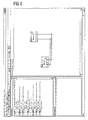
- the starting point is a device list. This includes several 1-way and 2-way buttons and some Actuators, as shown in Figure 1 in the left window is.
- the first step is shown in the device list Devices assigned to the rooms of the building, for example one Kitchen and living room.
- the wizards are used to interconnect the devices carried out.
- the first thing is a series connection in the kitchen projected.
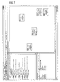
- the user must be the first to be switched Select actuator as indicated in FIG. 3 and after displaying a menu, the menu item "Connect series connection” select as illustrated by Figure 4 is.
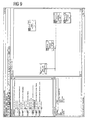
- the second actuator is selected, as indicated in the bottom left of FIG. 5.
- To Clicking on the actuator prompts you to press a 2-fold button to select. Is this by clicking on it the interconnection is complete and the Connections are drawn. This is shown in Figure 6.
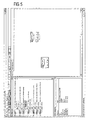
- the installer then implements a two-way circuit there for the ceiling lamp, as shown in Figure 7, in which is the window assigned to the living room next to the Window with the device list is shown.
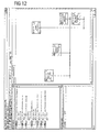
- FIG. 11 a configuration of a simple switch-off between buttons - Blinds - living room and blinds - actuator by one Selection of the blind actuator, a call of the associated wizard and a selection of the desired button. The result this process is shown in FIG.
Landscapes
- Engineering & Computer Science (AREA)
- Architecture (AREA)
- Civil Engineering (AREA)
- Structural Engineering (AREA)
- Air Conditioning Control Device (AREA)
Abstract
Description
Die Erfindung betrifft ein Verfahren und ein graphisches Werkzeug zum Projektieren von Elektroinstallationskomponenten eines Gebäudes.The invention relates to a method and a graphic Tool for configuring electrical installation components of a building.
Der Erfindung liegt folgendes technische Problem zugrunde: Elektroinstallationen in Gebäuden werden zunehmend unter Verwendung einer Bustechnik realisiert. Dabei sind alle zu schaltende Stromverbraucher (Lampen, Jalousie-Motoren, usw.) über Aktoren und die Sensoren (Taster, Kontakte, usw.) über einen Kommunikationsbus, wie beispielsweise den instabus ® EIB (European Installation Bus) in den Techniken Twisted Pair (TP), Radio Frequency (RF), Power Line (PL), miteinander verbunden. Die Stromverbraucher sind über die Aktoren auch direkt am 220V-Stromnetz angeschlossen. Das Schalten einer Lampe geschieht nun durch Senden einer Nachricht vom Sensor, beispielsweise einem Taster, zu dem Aktor mit der angeschlossenen Lampe. Damit dies funktioniert, müssen bei der Inbetriebsetzung diese Kommunikationsbeziehungen projektiert werden.The invention is based on the following technical problem: Electrical installations in buildings are increasingly being used implemented using a bus technology. All are closed switching electricity consumers (lamps, blind motors, etc.) via actuators and the sensors (buttons, contacts, etc.) via a communication bus, such as the instabus ® EIB (European Installation Bus) using the techniques of twisted pair (TP), Radio Frequency (RF), Power Line (PL), connected. The electricity consumers are also direct via the actuators connected to the 220V mains. Switching a lamp now happens by sending a message from the sensor, for example a button to the actuator with the connected one Lamp. In order for this to work, you have to commission it these communication relationships are configured.
Bisher fand diese Bustechnik hauptsächlich ihren Einsatz in Industriegebäuden, öffentlichen Gebäuden, Verwaltungsgebäuden, usw. Dort wurde die Inbetriebsetzung der Gebäudeleittechnik von geschulten Projektierern durchgeführt.So far, this bus technology has mainly been used in Industrial buildings, public buildings, administrative buildings, etc. There was the commissioning of the building management system carried out by trained project engineers.
Bei bisherigen Lösungen steht den Ingenieuren, die eine Gebäudeleittechnik im Zweckbau auf Basis des EIB in Betrieb nehmen, als PC-basiertes Werkzeug die EIB Tool Software (ETS) der European Installation Bus Association (http://www.eiba.com/a103.html) zur Verfügung. Dies ist ein Datenbank-basiertes graphisches Werkzeug, mittels dessen ein Projekt vollständig projektiert werden kann. Dabei steht der Kommunikationsbus im Mittelpunkt des Denkens. Gruppenadressen dienen dazu, Kommunikationsbeziehungen zwischen Geräten aufzubauen. Außerdem stellt der Einsatz des Werkzeuges Anforderungen an den Anwender, die nur durch spezielle Schulungen erlernbar sind.With previous solutions, the engineers have a building management system in functional building based on the EIB in operation the EIB Tool Software (ETS) as a PC-based tool the European Installation Bus Association (http://www.eiba.com/a103.html) is available. This is a Database-based graphic tool, by means of which a Project can be completely configured. It says Communication bus at the center of thought. Group addresses are used to establish communication relationships between devices. The use of the tool also places demands to the user who only through special training are learnable.
Als Alternative zur ETS gibt es Controller-Geräte zur Inbetriebsetzung von derartigen Installationen. Ein Beispiel dafür ist der Busch-Powernet® EIB Controller (http://www.catalogic.de/bje/katalog/d46c.htm) für Busch-Powernet® EIB Anlagen. Diese Controller haben ein Textdisplay mit 4-8 Zeilen. Es handelt sich also nicht um graphische Werkzeuge.As an alternative to the ETS, there are controller devices for commissioning of such installations. An example for is the Busch-Powernet® EIB controller (http://www.catalogic.de/bje/katalog/d46c.htm) for Busch-Powernet® EIB systems. These controllers have a text display with 4-8 lines. So it's not graphical Tools.
Ausgehend von diesem Stand der Technik liegt der Erfindung die Aufgabe zugrunde, einen Weg aufzuzeigen, wie auch im Heimbereich eine einfache Inbetriebnahme einer auf Bustechnik basierenden Elektroinstallation ermöglicht werden kann.The invention is based on this prior art based on the task of showing a way, as in Home area easy commissioning of a bus technology based electrical installation can be made possible.
Diese Aufgabe wird durch ein Verfahren mit den im Anspruch 1
angegebenen Merkmalen und ein graphisches Werkzeug mit den im
Anspruch 4 angegebenen Merkmalen gelöst. Vorteilhafte Ausgestaltungen
und Weiterbildungen der Erfindung ergeben sich aus
den abhängigen Ansprüchen.This object is achieved by a method with the in
Die Vorteile der Erfindung liegen darin, dass beispielsweise mittels eines einfachen, graphischen, Personal-Computer- oder Palmtop-basierten Werkzeugs ein Elektroinstallateur, der im Heimbereich Planer und Inbetriebsetzer in einem ist, in die Lage versetzt wird, ein einfaches EIB Projekt im Wohnbau schnell, kostengünstig und ohne Schulungsaufwand in Betrieb zu nehmen. Dabei kann der Installateur in seiner gewohnten Denkwelt verbleiben. Diese ist gekennzeichnet durch Schaltungen wie eine Ausschaltung, eine Wechselschaltung, eine Serienschaltung usw.. Realisiert wird dieser Ansatz durch sogenannte Assistenten (Wizzards), die dem Anwender helfen, derartige Schaltungen zu spezifizieren. The advantages of the invention are that, for example by means of a simple, graphic, personal computer or Palmtop-based tool an electrician who is in the Home planners and commissioners are all in one Relocation, a simple EIB project in residential construction in operation quickly, inexpensively and without training to take. The installer can do this in his usual way The world of thought remains. This is characterized by circuits like an opening, a two-way circuit, a series circuit etc. This approach is implemented by so-called Assistants (wizzards) that help the user To specify circuits.
Ausgangsbasis für die erfindungsgemäße Projektierung von Schaltungen ist eine Geräteliste. In dieser Geräteliste sind alle Geräte wie Taster, Zeitschaltuhren, Jalousie-Ansteuerungen, usw., für ein Projekt, beispielsweise ein Wohnhaus, enthalten. Geräte wie 2-fach-Taster oder 2-fach-Aktoren zum Ansteuern von 2 Verbrauchern bestehen wiederum aus 2 bzw. mehreren Gerätekanälen. Für die nachfolgende Beschreibung ist aber diese Unterscheidung zwischen Gerät und Gerätekanal nicht von Bedeutung. Es wird daher nur von Geräten gesprochen. Bei Geräten mit mehreren Kanälen ist das Wort Gerät durch Gerätekanal zu ersetzen.Starting basis for the project planning according to the invention Circuits is a device list. In this device list are all devices such as buttons, timers, blind controls, etc., for a project such as an apartment building. Devices such as 2-way buttons or 2-way actuators for control of 2 consumers consist of 2 or more Device channels. For the description below is but this distinction between device and device channel not significant. It is therefore only spoken of devices. For devices with multiple channels, the word is device to be replaced by device channel.
In einem ersten Schritt ordnet der Anwender in der Geräteliste enthaltene Geräte den Räumen seines Projektes bzw. Gebäudes zu. So kann er beispielsweise ein Wohnzimmer, einen Flur und eine Küche einrichten. Jeder Raum wird durch ein eigenes Fenster im Werkzeug dargestellt. Durch Verschieben von Geräten mit der Maus vom Fenster "Geräteliste" in das Fenster "Wohnzimmer" werden die Geräte dort platziert. Danach erfolgt eine Verschaltung der Geräte.In a first step, the user arranges in the device list devices contained in the rooms of his project or building to. For example, it can be a living room, a hallway and set up a kitchen. Each room has its own Window shown in the tool. By moving devices with the mouse from the "Device List" window into the window The devices are placed in the "living room". After that is done an interconnection of the devices.
Im einfachsten Falle will der Installateur beispielsweise eine Ausschaltung realisieren. Dazu wählt er den Aktor für eine Lampe aus. Über das Programm-Menü ruft er die Funktion "Verbinden - Ausschaltung" auf. Daraufhin wird er dazu aufgefordert, den zugehörigen Taster auszuwählen. Dazu muss er den Mauszeiger auf den gewünschten Taster schieben und das Symbol anklicken. Solange unter dem Mauszeiger kein geeigneter Sensor liegt, hat der Mauszeiger die Form eines Verbotsschildes und die Aktion kann nicht beendet werden. Nach dem Anklicken des Tasters ist die Verbindung hergestellt.In the simplest case, the installer wants one, for example Realize shutdown. To do this, he selects the actuator for one Lamp off. Via the program menu he calls the function "Connect - Shutdown ". He will then be asked to select the associated button. To do this, he has to Move the mouse pointer to the desired button and the symbol click. As long as there is no suitable sensor under the mouse pointer the mouse pointer has the shape of a prohibition sign and the action cannot be ended. After clicking the button is connected.
In gleicher Weiche verfährt der Anwender bei den anderen Schaltungen. Bei der Wechselschaltung muss er, ausgehend von einem Aktor, zunächst einen ersten Taster anwählen und danach einen zweiten Taster. Bei einer Kreuzschaltung wird er geführt, um beliebig viele Taster auszuwählen. Zur Serienschaltung wählt er zu Beginn einen 2-fach-Taster aus. Dann muss er der Reihe nach die beiden Aktoren auswählen. Weitere Schaltungen, die auf diese Weise realisierbar sind, sind eine Parallelschaltung, eine Gruppenschaltung und eine Zentralschaltung (EIN/AUS).The user follows the same course with the others Circuits. With the two-way circuit, it must start from an actuator, first select a first button and then a second button. In the case of a cross connection, it is guided to select any number of buttons. For series connection he selects a 2-way button at the beginning. Then he has to Select the two actuators in sequence. Other circuits, that can be realized in this way are a parallel connection, a group circuit and a central circuit (ON OFF).
Aus dieser graphisch erstellten Projektierinformation generiert das Werkzeug alle Kommunikationsbeziehungen, Adressen und Parameter, die für den Betrieb des Busses notwendig sind.Generated from this graphically created configuration information the tool all communication relationships, addresses and parameters that are necessary for the operation of the bus.
Bei der vorliegenden Erfindung werden in einem Werkzeug zur Projektierung/Inbetriebsetzung einer busorientierten Anlage, beispielsweise einer instabus® EIB-Anlage, Assistenten eingesetzt, die es dem Inbetriebsetzer gestatten, Schaltungen, wie er sie von der herkömmlichen Technik kennt, beispielsweise eine Wechselschaltung, usw., auf graphische Weise einfach und schnell zu beschreiben. Daraus werden alle Daten automatisch gewonnen, die zum Betrieb des Busses mit der spezifizierten Leistung notwendig sind. Zur besseren Übersicht beim Verschalten von Geräten werden die Geräte zunächst ihren Räumen, wo sie wirken bzw. eingebaut sind, zugeordnet. Dies geschieht graphisch unter Verwendung der drag & drop-Technik.In the present invention, in a tool for Project planning / commissioning of a bus-oriented system, for example an instabus® EIB system, assistants used, which allow the commissioning engineer to use circuits, as it is known from conventional technology, for example a changeover circuit, etc., graphically simple and to describe quickly. From this all data become automatic won to operate the bus with the specified Performance are necessary. For a better overview at Interconnecting devices, the devices are initially their rooms, where they work or are installed. this happens graphically using the drag & drop technique.
Die folgenden Figuren zeigen beispielhaft die graphische Darstellung einer Serienschaltung, wie sie schrittweise vom Anwender aufgebaut wird.The following figures show an example of the graphic representation a series connection, as gradually as the user is built up.
Das gezeigte Beispiel betrifft die Projektierung eines kleinen Wohnbau-Projektes. Ausgangspunkt ist eine Geräteliste. Diese beinhaltet mehrere 1-fach und 2-fach-Taster und einige Aktoren, wie es in der Figur 1 im linken Fenster dargestellt ist. Im ersten Schritt werden in der Geräteliste dargestellte Geräte den Räumen des Gebäudes zugeordnet, beispielsweise einer Küche und einem Wohnzimmer.The example shown concerns the configuration of a small one Housing project. The starting point is a device list. This includes several 1-way and 2-way buttons and some Actuators, as shown in Figure 1 in the left window is. The first step is shown in the device list Devices assigned to the rooms of the building, for example one Kitchen and living room.
In der Küche gibt es einen 2-fach-Taster zum Schalten von zwei Lampen (Decke, Wand), die an einen 2-fach-Aktor angeschlossen sind, wie es die Figur 2 zeigt, in welcher das der Küche zugeordnete Fenster neben dem Fenster mit der Geräteliste dargestellt ist.There is a 2-way button in the kitchen for switching two lamps (ceiling, wall) connected to a double actuator are, as shown in Figure 2, in which the Windows assigned to the kitchen next to the window with the device list is shown.
Das Verschalten der Geräte wird mit Hilfe der Assistenten durchgeführt. Als erstes wird eine Serienschaltung in der Küche projektiert. Dazu muss der Anwender den ersten zu schaltenden Aktor anwählen, wie es in der Figur 3 angedeutet ist, und nach Einblendung eines Menüs den Menüpunkt "Verbinden-Serienschaltung" auswählen, wie es durch die Figur 4 veranschaulicht ist. Danach erfolgt eine Auswahl des zweiten Aktors, wie es in der Figur 5 unten links angedeutet ist. Nach dem Anklicken des Aktors wird dazu aufgefordert, einen 2-fach-Taster auszuwählen. Ist dies durch entsprechendes Anklicken erfolgt, dann ist die Verschaltung abgeschlossen und die Verbindungen werden gezeichnet. Dies ist in Figur 6 gezeigt.The wizards are used to interconnect the devices carried out. The first thing is a series connection in the kitchen projected. To do this, the user must be the first to be switched Select actuator as indicated in FIG. 3 and after displaying a menu, the menu item "Connect series connection" select as illustrated by Figure 4 is. Then the second actuator is selected, as indicated in the bottom left of FIG. 5. To Clicking on the actuator prompts you to press a 2-fold button to select. Is this by clicking on it the interconnection is complete and the Connections are drawn. This is shown in Figure 6.
Im Wohnzimmer sind zwei 1-fach-Taster (Türe, Balkontüre) zum Schalten der Deckenlampe (2-fach-Aktor, nur einer wird benutzt) und ein 1-fach-Taster für die Jalousie vorgesehen.In the living room there are two single buttons (door, balcony door) for Switching the ceiling lamp (double actuator, only one is used) and a 1-fold button is provided for the blind.
Dort realisiert der Installateur anschließend eine Wechselschaltung für die Deckenlampe, wie aus Figur 7 hervorgeht, in welcher das dem Wohnzimmer zugeordnete Fenster neben dem Fenster mit der Geräteliste dargestellt ist.The installer then implements a two-way circuit there for the ceiling lamp, as shown in Figure 7, in which is the window assigned to the living room next to the Window with the device list is shown.
Nach Anwahl des Aktors für die Deckenlampe und dem Aufruf des Wizzards für eine Wechselschaltung ergeht eine Aufforderung, den ersten Taster/Sensor auszuwählen, wie es in Figur 8 dargestellt ist. Nach einer Auswahl des Tasters an der Türe ist der erste Teil der Schaltung realisiert und es ergeht die Aufforderung, den zweiten Sensor bzw. Taster auszuwählen, wie es in der Figur 9 angedeutet ist. Durch Anklicken des Tasters an der Balkontüre ist die Erstellung der Wechselschaltung abgeschlossen, wie aus der Figur 10 ersichtlich ist. After selecting the actuator for the ceiling lamp and calling up the Wizzards for a toggle switch are prompted select the first button / sensor, as shown in Figure 8 is. After selecting the button on the door the first part of the circuit is realized and the Request to select the second sensor or button, such as it is indicated in FIG. 9. By clicking the button the creation of the two-way circuit is completed on the balcony door, as can be seen from FIG. 10.
Schließlich erfolgt noch - wie aus der Figur 11 hervorgeht - eine Projektierung einer einfachen Ausschaltung zwischen Taster - Jalousie - Wohnzimmer und Jalousie - Aktor durch eine Anwahl des Jalousie-Aktors, einen Aufruf des zugehörigen Wizzards und eine Auswahl des gewünschten Tasters. Das Ergebnis dieses Vorganges ist in der Figur 12 dargestellt.Finally - as can be seen in FIG. 11 - a configuration of a simple switch-off between buttons - Blinds - living room and blinds - actuator by one Selection of the blind actuator, a call of the associated wizard and a selection of the desired button. The result this process is shown in FIG.
Aus der vorstehenden Beschreibung ist ersichtlich, dass mittels der Erfindung ein Elektroinstallateur ohne aufwendige Schulungsmaßnahmen dazu in die Lage versetzt wird, mittels eines einfachen, graphischen Werkzeuges für einen Personal-Computer oder einen Palmtop ein einfaches Installationsprojekt in einem Gebäude schnell und kostengünstig durchzuführen. Dabei kann er seine gewohnte Denkweise beibehalten, da es sich bei den zu projektierenden Elementen bzw. Schaltungen um herkömmliche Dinge wie eine Realisierung eines Ausschaltvorganges, einer Wechselschaltung oder einer Serienschaltung, etc., handelt.From the above description it can be seen that by means of the invention an electrician without expensive Training measures are enabled to use a simple, graphic tool for a personal computer or a palmtop a simple installation project in a building quickly and inexpensively. He can keep his usual way of thinking because the elements or circuits to be configured about conventional things like realizing a switch-off process, a two-way circuit or a series circuit, etc., acts.
Claims (5)
dadurch gekennzeichnet, dass
die Zuordnung eines Gerätes zu einem Raum durch ein Verschieben des Gerätes mittels eines Cursors aus der Geräteliste in das dem Raum zugeordnete Bildschirmfenster erfolgt.Method according to claim 1,
characterized in that
the assignment of a device to a room is done by moving the device by means of a cursor from the device list into the screen window assigned to the room.
dadurch gekennzeichnet, dass
die Verschaltung der im Bildschirmfenster platzierten Geräte unter Verwendung eines Assistenten, aufgerufen über ein Programm-Menü, erfolgt.The method of claim 1 or 2,
characterized in that
The devices placed in the screen window are connected using an assistant called up via a program menu.
dadurch gekennzeichnet, dass
es ein Personal-Computer oder ein Palmtop-basiertes Werkzeug ist.Graphic tool according to claim 4,
characterized in that
it is a personal computer or a palmtop-based tool.
Applications Claiming Priority (2)
| Application Number | Priority Date | Filing Date | Title |
|---|---|---|---|
| DE2000112279 DE10012279A1 (en) | 2000-03-14 | 2000-03-14 | System and method for the graphic interconnection of electrical installation components |
| DE10012279 | 2000-03-14 |
Publications (1)
| Publication Number | Publication Date |
|---|---|
| EP1134864A1 true EP1134864A1 (en) | 2001-09-19 |
Family
ID=7634608
Family Applications (1)
| Application Number | Title | Priority Date | Filing Date |
|---|---|---|---|
| EP01106267A Withdrawn EP1134864A1 (en) | 2000-03-14 | 2001-03-14 | Method and graphical apparatus for layout design of electrical components inside a building |
Country Status (2)
| Country | Link |
|---|---|
| EP (1) | EP1134864A1 (en) |
| DE (1) | DE10012279A1 (en) |
Cited By (2)
| Publication number | Priority date | Publication date | Assignee | Title |
|---|---|---|---|---|
| EP2180388A1 (en) * | 2008-10-23 | 2010-04-28 | Schneider Electric Industries SAS | Method for projecting a bus-oriented programmable electric installation |
| EP3080375B1 (en) | 2013-12-13 | 2018-06-20 | Walter Degelsegger | Device for closing an opening in a building |
Families Citing this family (2)
| Publication number | Priority date | Publication date | Assignee | Title |
|---|---|---|---|---|
| DE10222628B4 (en) | 2002-05-17 | 2004-08-26 | Siemens Ag | Method for evaluating a time signal that contains spectroscopic information |
| DE10311055B3 (en) * | 2003-03-13 | 2004-10-21 | Siemens Ag | Electrical system design method e.g. for building electrical installation or European Installation Bus, using supplied information for selecting permissible connections between hardware and/or software components and/or functions |
Citations (2)
| Publication number | Priority date | Publication date | Assignee | Title |
|---|---|---|---|---|
| FR2566593A1 (en) * | 1984-06-25 | 1985-12-27 | Labeyrie Ets | Method for designing an electrical network for a habitable building and prefabricated electrical installation obtained according to this method |
| DE19727469A1 (en) * | 1997-06-27 | 1999-02-25 | Elektro Ebert Gmbh | Assembly method of electrical installation e.g. for floor plan of flat |
-
2000
- 2000-03-14 DE DE2000112279 patent/DE10012279A1/en not_active Withdrawn
-
2001
- 2001-03-14 EP EP01106267A patent/EP1134864A1/en not_active Withdrawn
Patent Citations (2)
| Publication number | Priority date | Publication date | Assignee | Title |
|---|---|---|---|---|
| FR2566593A1 (en) * | 1984-06-25 | 1985-12-27 | Labeyrie Ets | Method for designing an electrical network for a habitable building and prefabricated electrical installation obtained according to this method |
| DE19727469A1 (en) * | 1997-06-27 | 1999-02-25 | Elektro Ebert Gmbh | Assembly method of electrical installation e.g. for floor plan of flat |
Cited By (2)
| Publication number | Priority date | Publication date | Assignee | Title |
|---|---|---|---|---|
| EP2180388A1 (en) * | 2008-10-23 | 2010-04-28 | Schneider Electric Industries SAS | Method for projecting a bus-oriented programmable electric installation |
| EP3080375B1 (en) | 2013-12-13 | 2018-06-20 | Walter Degelsegger | Device for closing an opening in a building |
Also Published As
| Publication number | Publication date |
|---|---|
| DE10012279A1 (en) | 2001-09-20 |
Similar Documents
| Publication | Publication Date | Title |
|---|---|---|
| DE69533925T2 (en) | LOCAL NETWORK FOR IMPLEMENTING A LOW VOLTAGE CONTROL | |
| EP1064759A1 (en) | Method for commissioning a bus system and corresponding bus system | |
| DE19546831A1 (en) | House and building services control and management | |
| EP2506096B1 (en) | Method for logically connecting sensors and actuators when starting up an installation system | |
| EP0825740B1 (en) | Circuit and method for controlling electric appliances | |
| DE10327504B4 (en) | Multifunction device | |
| EP1134864A1 (en) | Method and graphical apparatus for layout design of electrical components inside a building | |
| EP1973208B1 (en) | Method for operating and programming switches, in particular light switches | |
| EP1345097B1 (en) | Method and device for creating a control-layer in a building automation system | |
| DE102012008459A1 (en) | Concealed electrical installation equipment Modular System | |
| EP2455827A1 (en) | Field device with energy saving mode, that can be activated and deactivated over both of the two interfaces of the field device | |
| EP2523396A2 (en) | Portable display and operation device | |
| DE102016104347B4 (en) | Simplified commissioning concept for controlling actuators in a building installation | |
| DE102007040425A1 (en) | Field device i.e. inverter, for connection to bus e.g. field bus, realizes two logical slaves with address operation, and detection device detects action that is conducted on field device and independent of bus | |
| DE10034774A1 (en) | Remote control device for drives of locking devices for building openings | |
| DE29912385U1 (en) | Central house control | |
| EP2180388B1 (en) | Method for projecting a bus-oriented programmable electric installation | |
| EP3088975B1 (en) | Channel related device parameterization | |
| DE4327718B4 (en) | A method for user-definable functional assignment of an electrotechnical activator to an activatable object and the arrangement operating according to the method | |
| EP0874343A2 (en) | System for comfortable mobile operation, monotoring and for data exchange | |
| EP3847516B1 (en) | Control device identification in an automated system | |
| DE102004051834B4 (en) | Testing unit for programmable electrical installations, especially building installations with an electronic control bus, has a gateway to the installation via which the data of individual network members or units can be accessed | |
| DE10312183A1 (en) | Micro controller based bus system is used in rooms and buildings for operation of services such as heating and lighting | |
| EP1971080B1 (en) | Method for operating a radio system | |
| EP3657286B1 (en) | Method for configuring an actuator device in a building automation system |
Legal Events
| Date | Code | Title | Description |
|---|---|---|---|
| PUAI | Public reference made under article 153(3) epc to a published international application that has entered the european phase |
Free format text: ORIGINAL CODE: 0009012 |
|
| AK | Designated contracting states |
Kind code of ref document: A1 Designated state(s): AT CH DE FR GB IT LI Kind code of ref document: A1 Designated state(s): AT BE CH CY DE DK ES FI FR GB GR IE IT LI LU MC NL PT SE TR |
|
| AX | Request for extension of the european patent |
Free format text: AL;LT;LV;MK;RO;SI |
|
| 17P | Request for examination filed |
Effective date: 20011023 |
|
| AKX | Designation fees paid |
Free format text: AT CH DE FR GB IT LI |
|
| STAA | Information on the status of an ep patent application or granted ep patent |
Free format text: STATUS: THE APPLICATION IS DEEMED TO BE WITHDRAWN |
|
| 18D | Application deemed to be withdrawn |
Effective date: 20031001 |