EP3392987B1 - Method and system for automated support of a connection process, in particular for components in a switch cabinet or on a mounting system - Google Patents
Method and system for automated support of a connection process, in particular for components in a switch cabinet or on a mounting system Download PDFInfo
- Publication number
- EP3392987B1 EP3392987B1 EP17167566.3A EP17167566A EP3392987B1 EP 3392987 B1 EP3392987 B1 EP 3392987B1 EP 17167566 A EP17167566 A EP 17167566A EP 3392987 B1 EP3392987 B1 EP 3392987B1
- Authority
- EP
- European Patent Office
- Prior art keywords
- wiring
- connection
- connecting line
- identifier
- user output
- Prior art date
- Legal status (The legal status is an assumption and is not a legal conclusion. Google has not performed a legal analysis and makes no representation as to the accuracy of the status listed.)
- Active
Links
Images


Classifications
-
- H—ELECTRICITY
- H02—GENERATION; CONVERSION OR DISTRIBUTION OF ELECTRIC POWER
- H02B—BOARDS, SUBSTATIONS OR SWITCHING ARRANGEMENTS FOR THE SUPPLY OR DISTRIBUTION OF ELECTRIC POWER
- H02B3/00—Apparatus specially adapted for the manufacture, assembly, or maintenance of boards or switchgear
-
- H—ELECTRICITY
- H02—GENERATION; CONVERSION OR DISTRIBUTION OF ELECTRIC POWER
- H02B—BOARDS, SUBSTATIONS OR SWITCHING ARRANGEMENTS FOR THE SUPPLY OR DISTRIBUTION OF ELECTRIC POWER
- H02B1/00—Frameworks, boards, panels, desks, casings; Details of substations or switching arrangements
- H02B1/015—Boards, panels, desks; Parts thereof or accessories therefor
- H02B1/04—Mounting thereon of switches or of other devices in general, the switch or device having, or being without, casing
Definitions
- the invention relates to a method with the features of the preamble of claim 1. Furthermore, the invention relates to a system with the features of the preamble of claim 5, in particular for performing the method described above. The invention also relates to the use of the system and a computer program. Such a method and system is known from US Pat WO 2016/202454 A1 known. Another method of making a wire harness is from US Pat DE 199 18 212 A1 known.
- Control cabinets are primarily used to supply systems or electrical installations with electrical energy and sometimes also with signals, for example to control a system or electrical components.
- a large number of electrical, electronic and sometimes also pneumatic or hydraulic components are typically housed in a switch cabinet.
- further electrical and electronic components can also be installed in or on a switch cabinet, which are used, for example, for air conditioning, lighting or for monitoring the switch cabinet.
- connection lines in accordance with a specified connection plan, for example a wiring plan, a tubing plan, a piping plan or a combination thereof, whereby the requirements for the individual Connection line can differ depending on the type of connection, for example because the lines must be designed for different currents, operating frequencies, cross-sections or for the transmission of data.
- Wiring diagrams are used in particular to connect electrical components; Hose and piping plans are used in particular to connect pneumatic or hydraulic components.
- a control cabinet can be fitted with the corresponding components at the factory or directly on site.
- the connection, in particular the wiring of the components can also be carried out at the factory or directly on site and is carried out manually by a technician.
- the expansion or modification of existing control cabinets also requires manual wiring, tubing or piping by a technician, in particular an electrical engineer, if factory, possibly automated wiring, tubing or piping is not possible in such cases.
- the technician performing the wiring / tubing / piping can, for example, use the information in a given circuit diagram and his know-how to determine the individual connections to be made, localize the associated connection points in the control cabinet, and use suitable connection lines for the individual connections, in particular with suitable cross-sections or from suitable materials and use them to carry out the wiring / tubing / piping.
- the technician can also proceed according to a so-called wiring, tubing and / or tubing list, in which the wiring / tubing / tubing to be carried out already exists are specified and listed.
- the technician can then work through the connections listed in the wiring, tubing and / or tubing list one after the other by using his know-how to manually locate the respective connection points of the individual wirings, determine the routing paths, and then carry out the wiring / tubing / tubing accordingly.
- connection lines required for wiring / tubing / piping There are also various methods of manufacturing the connecting lines required for wiring / tubing / piping: In this way, the technician can use his know-how to select the type of connection cable required for the individual connections himself and produce (assemble) the corresponding connection cables himself on site during the connection process. To produce the connecting lines, he can in particular cut the connecting lines to length and assemble them, for example, apply wire end treatments and / or labels.
- the connecting lines can also be automatically or manually defined and pre-assembled in advance before the technician carries out the wiring / piping / tubing.
- a so-called virtual routing can be carried out during the work preparation prior to the actual wiring / tubing / tubing, in which the wiring / tubing / tubing of the control cabinet is planned in advance, preferably with software support, so that each connecting line has a length,
- the type of connection, type of assembly and, if applicable, type of labeling is defined in advance.
- the laying routes can already be defined in advance and, if necessary, stored in a data format (such as a CAx format).
- connection line By pre-assembling the connection line and defining the laying paths in advance, the wiring / tubing / piping of a control cabinet is already significantly simplified, since the technician does not have to select the type of connection line himself, does not have to assemble the connection lines himself and preferably does not have to determine the laying paths himself.
- the present invention is based on the object of providing a method and a system with which in particular such a wiring process can be effectively supported, so that the wiring is made easier for the technician, incorrect wiring is avoided and the wiring process as a whole contributes increased quality is accelerated.
- this object is achieved by a method, characterized in that the generation of the visual user output includes the generation of a graphic representation of the connection points and the route of the connection line
- connection process or the connection of components arranged in a switch cabinet or on an assembly system is the connection of Understood connecting lines on or between the components that are arranged in a switch cabinet or on a mounting system, for example a mounting plate.
- the mounting system can be arranged in a control cabinet or be intended for such. Alternatively, it can be an independent assembly system that can also be used without a control cabinet, for example directly on a machine.
- connection process can in particular be a wiring process in which connecting lines for the wiring, such as, for example, individual wires or cables, are connected.
- connection lines for pneumatic or hydraulic components for example hoses or pipes
- connection process thus includes wiring processes, tubing processes, piping processes and also combinations thereof.
- the connection process itself is carried out manually by a technician; however, he is supported automatically by the method or system described above. In particular, the method and the system help him to unambiguously assign the pre-assembled connection lines, to identify the associated connection points and preferably also to adhere to a specified routing path by providing the technician with the information required for this purpose for the next connection line selected by him provides.
- a switch cabinet is understood to mean a device for accommodating electrotechnical, hydraulic and / or pneumatic components.
- the switch cabinet forms an enclosure to protect the components, in particular from external influences and, if necessary, from being seen. Such an enclosure also preferably enables targeted heat dissipation from the components installed in it.
- assembly systems are generally used which are known as assembly plates or assembly frames and which are built into the control cabinet. The components are mechanically fastened to these assembly systems. Furthermore, assembly systems can also be used independently of a control cabinet.
- the switch cabinet preferably has a cabinet door through which the interior of the housing is accessible so that the components can be assembled and connected.
- the components are, in particular, control technology components.
- the switch cabinet can be a switch cabinet for electrotechnical components and possibly additional hydraulic and / or pneumatic components.
- the switch cabinet can also be provided exclusively for hydraulic and / or pneumatic components.
- An assembly system is understood to mean systems that are used to install components in a control cabinet or independently of it.
- the mounting system can be, for example, a mounting frame or a mounting plate.
- a mounting plate is understood to be a plate that is used for the arrangement and mechanical fastening within a control cabinet.
- the components arranged on a mounting plate are then connected to one another via suitable electrical, pneumatic or hydraulic connections.
- the mounting plate preferably has mounting means such as bores or rails, on which the electrical and electronic components can be mounted.
- such a mounting plate can form part of a control cabinet.
- an identifier of a connecting line is detected by means of a detection device.
- the identification is preferably detected optically, for example by means of a camera or by means of a scanner, for example a laser scanner.
- the detection device of the system preferably has a camera or a scanner, for example a laser scanner.
- the identifier can, for example, simply be printed on a connecting line, as a result of which the identifier can be produced very easily and inexpensively.
- An identifier of a connecting line is understood to mean an identifier that is assigned to a specific connecting line.
- the identifier is preferably attached directly to the connecting line, for example printed on it.
- the identifier can be a barcode or QR code, for example.
- the identifier can also be a character sequence, for example made up of numbers, letters and / or other symbols, which can be recorded by the detection device and recognized, for example, by an image analysis method known per se.
- the identifier can be a numeric or alphanumeric code, possibly also with special characters.
- the identifier identifies the connection line. This means that the connection line can be distinguished from other connection lines by means of the identifier.
- the identifier is preferably selected such that it uniquely identifies the connection line within a set of several connection lines for connecting, in particular for wiring, components arranged in a switch cabinet or on a mounting system, for example a mounting plate. If a number of connecting lines are provided for connecting, in particular for wiring, components arranged in a switch cabinet or on a mounting system, e.g. a mounting plate, the identifiers of the individual connecting lines preferably differ from one another, so that each individual connecting line can be identified by its identifier can be clearly identified. Includes the crowd Connecting lines for connecting, in particular for wiring components arranged in a control cabinet or on a mounting system, eg a mounting plate, several connecting lines of the same type and length, so in one embodiment they can also have identical or partially identical identifiers.
- a visual user output about the connection of the connection line identified by the identifier is generated depending on the detected identifier and a connection diagram.
- the visualization device of the system is set up to generate a visual user output on the connection of the connection line identified by the identifier, depending on the detected identifier and a connection diagram.
- the connection diagram can be a wiring diagram, for example, and the visualization device can be set up accordingly to generate a visual user output via the wiring of the connection line identified by the identifier, depending on the detected identifier of the wiring plan.
- a user output about the connection and the wiring of the connecting line identified by the identifier is understood to mean a user output that receives instructions for connecting and wiring the identified connecting line.
- the instructions for connecting and wiring are in graphic form, with the user output containing a graphic representation of the connection points of the connection line and the route of the connection line.
- visualization software is preferably used, which, for example, can be stored in a memory of the system and can be executed on at least one processor of the visualization device.
- the user output about the connection, in particular about the wiring, is generated as a function of the detected identifier.
- the user output can be specifically adapted to the connection line identified by the identifier, so that the user specifically receives the instructions for connecting, in particular for wiring, the connection line selected by him.
- connection plan is understood to mean a plan which assigns information for their connection to the individual connecting lines, in particular the connection points of the respective connecting line and the route of the respective connecting line.
- the connection diagram can for example be stored on a memory of the system so that it can be called up by the visualization device.
- the connection diagram can in particular be a wiring diagram that assigns information for their wiring to the individual connecting lines.
- the connection plan can also be a tubing plan and / or a piping plan that assigns information to the individual connecting lines for their connection, in particular by means of hoses and / or pipes.
- the connection plan can also be a combination of a wiring plan, a tubing plan and / or a piping plan.
- connection diagram in particular the wiring diagram
- the connection diagram can be saved, for example, in the form of a virtual model, in particular a two- or three-dimensional model, of the control cabinet or the mounting plate, which on the one hand contains information about the control cabinet (or the mounting plate) and the information contained therein (or . Thereon) arranged components and on the other hand information about the Comprises pre-assembled connection lines for connecting the individual components, in particular the respective connection points and the respective laying path of the connection lines.
- the user output is output via an output device.
- the output device is preferably a screen, a projector, data glasses or a combination of a screen, a projector and / or data glasses.
- the output device can in particular also be a screen of a mobile device, such as a smartphone or tablet computer.
- a technician can automatically record the identification of a connection line after selecting a connection line and then carry out the installation of the connection line in question using the user output output via the output device.
- a detection unit not belonging to the invention for detecting an identifier of a connection line with a detection area in which a connection line to be identified can be positioned, with a camera module which is set up to detect image data from a connection line positioned in the detection area, with a Control device which is set up to find an identifier of a connection line in the captured image data and to generate a digital code for the identifier found, and with a transmission device which is set up to send the digital code for the identifier found to a visualization device for generating a User output via the connection, in particular via the wiring, of the connection line identified by the identifier.
- the detection area preferably comprises a receptacle into which a connecting line to be identified can be inserted.
- Camera module preferably set up to capture image data from a connecting line inserted into the receptacle.
- the receptacle is preferably designed such that it at least partially surrounds a section of the connecting line.
- the receptacle can be designed in the form of a channel into which the connecting line can be inserted or pushed.
- the channel can, for example, be open on one or both sides.
- the receiving device is preferably dimensioned such that it enables the detection of an identifier at different positions on the connecting line, for example at the end of the wire, continuously along the wire or at a certain point on the connecting line, for example at a certain distance from the wire end.
- the acquisition unit also has a camera module which is set up to acquire image data from a connection line positioned in the detection area, in particular a connection line inserted into the preferably provided receptacle.
- the camera module is arranged in particular in the area of the recording. If the receptacle is in the form of a channel, for example, then the camera module is preferably arranged within the channel or on the channel wall.
- the receptacle preferably has a characteristic such as, for example, an edge, which is arranged in the field of view of the camera module. In this way, the positioning of the connecting line in the receptacle is facilitated in order to position the identifier in the field of view of the camera module.
- the acquisition unit preferably has a screen on which the image data acquired by the camera module are output. This makes it easier to position the connecting line in the receptacle so that the identifier can be detected by the camera module.
- the detection unit preferably has an illumination device that illuminates the field of view of the camera module. If the receptacle is designed in the form of a channel, the lighting device is preferably arranged within the channel or on the channel wall.
- the lighting device is preferably designed and arranged to evenly illuminate a curved surface on a connecting line such as a cable, a pipe or a hose. In this way, an identifier printed on the connecting line can be reliably detected.
- the lighting device is preferably designed and arranged in such a way that a connecting line can be uniformly illuminated transversely to its direction of extension over an angular range of at least 180 °, preferably at least 270 °.
- the lighting device can at least partially surround the preferably provided receptacle or be arranged on several sides of the receptacle.
- the acquisition unit also has a control device which is set up to find an identifier of a connection line in the acquired image data.
- the control device can in particular have at least one processor and a memory with a program for analyzing image data, the execution of which on the at least one processor triggers an image analysis of the image data captured by the camera module in order to include an identifier of a connection line, for example a Find a string of characters such as a numeric code or a barcode or QR code.
- the control device is also set up to generate a digital code for the identifier found. If the image data contains, for example, an image of an identifier in the form of a character string (e.g. image data of the character string "A38BX”) or a bar or QR code, the control device is preferably set up to provide a digital representation of the character string (in the example the digital character string (String) "A38BX") or the message encoded in the bar or QR code produce. This conversion of the image data into a digital code enables it to be further processed digitally.
- a character string e.g. image data of the character string "A38BX”
- the control device is preferably set up to provide a digital representation of the character string (in the example the digital character string (String) "A38BX") or the message encoded in the bar or QR code produce. This conversion of the image data into a digital code enables it to be further processed digitally.
- the detection unit also has a transmission device that is set up to transmit the digital code for the identifier found to a visualization device for generating a user output via the connection, in particular via the wiring, of the connection line identified by the identifier.
- the transmission device can include, for example, a transmission device via which the digital code can be transmitted to a server, for example via a standardized interface such as a network interface, with a digital transmission protocol on which visualization software for generating a user output can be connected, in particular via the Wiring of the connection line identified by the identifier.
- a visualization unit is integrated into the detection unit, which is set up to generate a user output about the connection, in particular the wiring, of the connection line identified by the identifier.
- the user output can be generated directly in the registration unit and preferably on a user output device of the registration unit or on an output unit connected to the registration unit via a communication link, such as data glasses or the like. are displayed.
- the transmission of the digital code can take place purely in software, for example by transferring a variable with the digital code for the identifier to a visualization module.
- the detection unit can be designed as a stationary or mobile unit.
- the detection unit preferably comprises an enclosure that protects the individual components of the detection unit from environmental influences such as dust, moisture, moisture and the like. protects.
- the preferably provided receptacle can in particular be formed by the housing, in which Housing then preferably a lighting device is integrated in order to uniformly illuminate a curved surface of a connecting line positioned in the receptacle.
- connection process in particular a wiring process of components arranged in a switch cabinet or on a mounting system, such as a mounting plate.
- a computer program comprising commands which, when the program is executed by a computer, cause the computer to carry out the method described above.
- a computer program can be stored, for example, in a memory of the system or of the acquisition unit so that it can be executed on the respective control device.
- the technician is required to connect, in particular for wiring, in a control cabinet or on a mounting system, e.g. If a number of pre-assembled connection lines are available on a mounting plate, arranged components, the connection, in particular the wiring, of the components arranged in the control cabinet or on the mounting plate is significantly simplified, since the technician does not have to determine and manufacture the type and length of the individual connection lines himself .
- the method and system described here also overcome the previous problem from the prior art that with a large number of pre-assembled connection lines for connection, in particular for wiring in a control cabinet or on an assembly system, e.g. a mounting plate, arranged components the technician can only with difficulty distinguish the individual connecting lines.
- the method and the system are set up to facilitate the connection, in particular the wiring, of in a control cabinet or on a mounting system, e.g. a mounting plate, to support arranged components with pre-assembled connecting lines by providing the technician with the information required for connecting, in particular for wiring, the individual connecting lines on request, the technician can do the connection, in particular the wiring that is in the control cabinet or . perform components arranged on the mounting plate much more easily.
- the visualization device is preferably set up to generate visual user outputs via the connection, in particular the wiring of the individual connection lines of the set of pre-assembled connection lines.
- the connection diagram in particular the wiring diagram, preferably includes information about the connection, in particular about the wiring of the individual connecting lines from the set of Connection lines, in particular via the respective connection points and the respective laying path.
- the user output is generated by means of a virtual model of the control cabinet or the assembly system with a representation of the connection, in particular the wiring, of the identified connecting line.
- the visualization device is set up to generate the user output with a representation of the connection, in particular the wiring of the identified connecting line, by means of a virtual model of the control cabinet or the assembly system. In this way, the technician carrying out the connection, in particular the wiring, can intuitively and graphically see instructions for connection, in particular for wiring the identified connecting line, so that the connection, in particular the wiring, is simplified.
- the user output can show a representation of the control cabinet or the assembly system and the components arranged on it with a representation of the identified connecting line in the completely connected, in particular wired, position.
- the connection diagram, in particular the wiring diagram can be at least partially formed by the virtual model of the control cabinet or the assembly system.
- the connection diagram, in particular the wiring diagram can include, for example, an assignment list in which a virtual model of the respective connecting line is assigned to the identifiers for identifying the individual connecting lines.
- the user output is output via an augmented reality device, with a real image or a real object being overlaid with the generated user output.
- the system includes an augmented reality device that is set up to output the user output to the user, with a real image or a real object is superimposed on the generated user output.
- the augmented reality device thus in particular forms the output device of the system.
- An augmented reality device is understood to mean a device that is set up to expand the user's perception of reality with the aid of a computer.
- the augmented reality device can in particular display a real image, for example an image recorded by a camera, and overlay it with additional information, for example in text and / or image form.
- additional information for example in text and / or image form.
- the superimposition of the real image with the additional information can be carried out by the visualization device.
- the augmented reality device can project information, for example in text and / or image form, into the user's field of vision, for example on an at least partially transparent screen like a head-up display or directly on the user's retina as with some data glasses.
- the augmented reality device can also be set up to superimpose the user output on a real object, in particular the switch cabinet or the assembly system and / or the components arranged therein or on it.
- the augmented reality device can, for example, have a projection unit which is set up to project the user output directly onto the real object, for example the switch cabinet or the assembly system and / or the components arranged therein or on it.
- the user output is projected onto the switch cabinet or the assembly system and / or the components arranged therein or on it that the connection points and the routing path for the identified connection line are directly on the real switch cabinet or the real assembly system and / or the therein or . components arranged on it are displayed.
- the augmented reality device is preferably data glasses. This can, for example, have one or two screens to display the generated User output and the real image or a projection unit for displaying the user output by projection onto the retina of the wearer. By wearing data glasses, the technician can keep his hands free to connect, especially the wiring of the control cabinet or the mounting plate.
- the augmented reality device can also be a smartphone or a tablet PC.
- smartphones and tablet PCs usually also have a camera with which it is possible on the one hand to record an identifier for a connection line and on the other hand to record a real image of the control cabinet or mounting plate.
- today's smartphones and tablet PCs have sufficient computing power to generate a visual user output about the connection, in particular the wiring, of the connection line for the connection line identified using the detected identifier.
- the user output can also be generated on a server with which the augmented reality device communicates via a communication connection such as a network connection.
- a real image of the control cabinet or the assembly system and / or the components arranged therein or thereon is captured and with a virtual image of the control cabinet or the assembly system and / or the components arranged therein or on it / or superimposed with a virtual image of the identified connecting line.
- the visualization device is set up to display a real image of the switch cabinet or the assembly system and / or the components arranged therein or thereon with a virtual image of the switch cabinet or the assembly system and / or those arranged therein or on it Superimpose components and / or with a virtual image of the identified connecting line.
- the system has a detection device for capturing an image of the control cabinet or the assembly system and / or the data contained therein or components arranged thereon.
- the acquisition device provided for acquiring the identifier can be used to acquire a real image of the switch cabinet or the assembly system and / or the components arranged therein or thereon.
- the real image is superimposed on the user output in such a way that a representation of the identified connection line is displayed in the real image of the control cabinet or the assembly system and / or the components arranged therein or on it, preferably at the position to be laid. In this way, the user can intuitively see immediately how the identified connection line is to be connected and laid.
- a user input about the connection in particular about the wiring of another connection line identified at an earlier point in time, is received and the user output about the connection, in particular the wiring of the connection line identified, is preferably dependent on the user input via the connection made, in particular the completed wiring of the other connection line is generated.
- the system comprises an input device which is set up to receive user inputs about the connection, in particular the wiring, of previously identified connection lines.
- the visualization device is preferably set up to generate the user output about the connection, in particular the wiring, of an identified connecting line depending on user inputs about the connection, in particular the wiring, of other previously identified connection lines. In this way the user can report this back to the system after the connection, in particular the wiring, of a connection line, so that a log of the connection, in particular the wiring, is possible. It is also possible to use the to adapt further user outputs to the current status of the connection process, in particular the wiring process.
- a representation of a virtual switch cabinet or a virtual mounting plate included in the user output can also include representations of previously connected, in particular wired, connecting lines so that the representation of the switch cabinet or the mounting plate better corresponds to the current installation situation and the technician can determine the position of the can recognize currently identified connecting line relative to the previously laid connecting lines.
- the system has a control device which is set up to carry out the previously described method or an embodiment thereof.
- the system includes in particular a memory on which a computer program, in particular the computer program described above, is stored, the execution of which on at least one processor of the control device causes the method to be carried out.
- a virtual model of the control cabinet to be produced or the assembly system to be produced, in particular with the components to be arranged therein or thereon, is generated and the connection diagram, in particular the wiring diagram, is produced on the basis of the virtual model.
- the connection lines required for connecting, in particular for wiring, the individual components can be defined, for example with regard to their type, their length and / or their routing paths.
- the connection plan, in particular the wiring plan is then preferably generated on the basis of the connecting lines defined in this way.
- the connection diagram generated in this way, in particular the wiring diagram can for example be stored in a memory of the system.
- connection lines can be assembled on the basis of the definition of the connection lines required for connection, in particular for wiring, so that a number of suitable pre-assembled connection lines are available for connection, in particular the wiring, of the components arranged in the switch cabinet or on the assembly system .
- connection lines defined on the basis of the virtual model of the control cabinet or the assembly system are each assigned the identifier that identifies the connection line in question and can be applied, in particular printed, directly to the connection lines in question when they are assembled.
- the connection diagram, in particular the wiring diagram is preferably generated in such a way that the identifiers of the individual connecting lines are assigned to the information for connection, in particular for wiring, of the respective connecting lines. In this way, the information for connecting, in particular for wiring, a connecting line for generating the user output as a function of the identifier can be retrieved from the connection diagram, in particular the wiring diagram.
- FIGS. 1-10 show systems and methods for automated support of a wiring process.
- the systems and methods can also be provided and designed to create connecting lines for pneumatic or hydraulic connections, i.e. in particular for the automated support of a piping or tubing process.
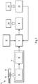
- FIG. 1 shows a first embodiment of the system according to the invention in a schematic representation.
- the system 2 for the automated support of a connection process of components arranged in a control cabinet or on a mounting system such as a mounting plate comprises a detection device 4, a visualization device 6 and an output device 8.
- the detection device 4 is set up to detect an identifier 10 of a connecting line 12.
- the detection device 4 can have, for example, a camera 14 or, alternatively, a scanner such as a laser scanner.
- the processing device 16 examines the image data recorded with the camera 14 by means of image processing techniques for the presence of an identifier for a connection line and generates a digital code for the identifier found so that the captured identifier is further processed in the form of the digital code by the visualization device 6 to generate a user output can be.
- the visualization device 6 is set up, depending on the detected identifier and a connection diagram, for example a wiring diagram 18, a visual user output 20 about the connection, for example via the wiring, of the connection line 12 identified by the identifier 10 produce.
- the connection diagram 18 can be stored, for example, on an electronic memory of the system 2 and contains information about the respective connection points and routing paths of the connecting lines to be connected.
- the visualization device 6 retrieves the information about the connection, for example about the wiring, of the connection line 12 identified using the detected identifier 10 from the connection diagram 18 and generates a corresponding graphic representation, for example with a schematic representation of the control cabinet and a highlighted representation of the identified connecting line 12 in the laid state.
- the output device 8 is finally set up to output the user output 20 generated by the visualization device 6 to a user.
- the output device 8 can have a screen, for example.
- the system 2 can also be set up to generate the user output 20 as an augmented reality display.
- the visualization device 6 for generating the user output 20 can, for example, superimpose an image captured by the camera 14 of the switch cabinet with the components to be connected, in particular wired, with a highlighted representation of the identified connecting line 12 in the connected state.
- the system 2 can also have an input device 22 which is set up to receive a user input 24 via the connection of a previously identified connection line. In this way, the system 2 can log the connection process actually carried out by the technician.
- the visualization device 6 can also be set up to generate the user output 20 via the connection of the identified connection line also depending on the previously received user input 24 via the connection of connection lines.
- the user output 20 can also include representations of further connecting lines for which user inputs 24 have been received about the routing thereof. This allows the user, for example, better orientation at the control cabinet by being able to read the position of the connecting line to be newly connected to the connecting lines 12 that are already connected from the user output 20.
- the example also includes an embodiment of the method for automated support of a connection process, in particular a wiring process, of components arranged in a switch cabinet.
- connection line 12 selects a connection line 12 from a set of pre-assembled connection lines with respective identifiers available to him for connecting components arranged in a switch cabinet and positions the identifier 10 on the selected connection line 12 in front of the camera 14 of the detection device 4, see above that the detection device 4 detects the identifier 10 of the selected connecting line 12 and generates a digital code for the identifier 10, which is transferred to the visualization device 6.
- the visualization device 6 uses the digital code for the identifier 10 from the connection diagram 18 to call information about the connection of the identifier 10 identified connecting line 12 and uses this information to generate a user output 20, for example with a graphical representation of the control cabinet and a representation of the identified connecting line 12 in the connected state.
- the generated user output 20 is then output via the output device 8, so that the technician can extract the information necessary for connecting the selected connecting line 12 and perform the connection manually.
- the technician can enter this as user input 24 on the input device 22 after the selected connection line 12 has been connected and laid.
- the technician can then select the next connection line from the set of pre-assembled connection lines and position its identifier in front of the camera 14, whereupon the previously described process run for the new connection line runs again. In this way, the technician can gradually call up the information required for laying the individual pre-assembled connection lines automatically, so that laying errors are avoided.
- the visualization device 6 can take this into account when generating the user output 20, for example by also showing the connection lines already laid in the graphical representation of the control cabinet in order to simulate the real view of the control cabinet in this way and to simplify the connection of the current connection line 12 for the technician.
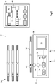
- FIG. 10 shows a further exemplary embodiment of a system 32 for the automated support of a connection process, in particular a wiring process, from FIG Components arranged in a switch cabinet 34 with a quantity 36 of pre-assembled connection lines 38.
- the connection lines 38 can, for example, have been defined in advance on the basis of a virtual routing on a virtual model of the switch cabinet 34 and then correspondingly assembled. In this way, before the start of the connection process, the technician has the connection lines 38 required for this, each with the correct type and length and, if necessary, with the correct connections.
- the individual connecting lines 38 are each printed with identifiers 40 by means of which the connecting lines 38 can be distinguished from one another.
- the identifiers 40 preferably allow a unique identification of the individual connecting lines 38 within the set 36.
- the identifiers 40 are shown as an example as a barcode. However, other identifiers are also conceivable, for example character strings printed on the connecting lines 38.
- the system 32 for supporting the connection process comprises a mobile device 46, for example in the form of a smartphone or a tablet computer, with a camera module 48, a user interface 50 in the form of a touchscreen and a control device 52 with at least one processor 54 and an electronic device connected to it Memory 56 and interfaces 58 and 60 for communication with the camera module 48 and the touchscreen 50.
- a computer program is stored in the memory 56 of the control device 52, the execution of which on the at least one processor 54 of the control device 52 enables a method to automatically support a connection process the components arranged in the control cabinet 34 causes.
- the camera 48 is set up to capture image data and the control device 52 is set up, when executing the computer program stored in the memory 56, to analyze the image data received via the interface 58 from the camera 48 to determine whether it has an identifier 40 ′ Connection line 38 'from the set 36 and, if this is the case, to generate a digital code for the identifier 40'.
- a list with the identifiers 40 of the connecting lines 38 from the set 36 can be stored in the memory 56, so that the control device 52 can determine by comparing the generated code with the identifiers stored in the list whether the detected identifier 40 'to a connecting line 38' from the set 36 for connecting, in particular for wiring, the components arranged in the switch cabinet 34.
- the camera 48 can be set up to permanently capture image data, and the control device 52 can be set up to continuously search through the captured image data for an identifier until an identifier 40 ′ is positioned when a connecting line 38 ′ from the set 36 is in front of the camera 48 is recognized.
- the control device 52 can also be set up to search through an image captured by the camera 48 for an identifier in response to a user input via the touchscreen 50.
- connection diagram for example a wiring diagram
- the connection diagram can be stored in the form of a virtual model of the control cabinet 34 which, in addition to information about the control cabinet, for example about its dimensions and the components to be arranged or arranged therein, also contains information about the connection points and / or the routing paths of the connecting lines 38 .
- the information on the individual connecting lines 38 is preferably assigned the associated identifier 40 of the connecting line 38, so that the Control device 52 can retrieve the information for the connection line 38 currently to be connected from the connection diagram as a function of the detected identifier 40 'or the digital code for it and use it for generating the user output.
- control device 52 After the generation of the user output, the control device 52 causes it to be displayed on the touchscreen 50, so that the technician receives the information via the touchscreen 50 that he needs to connect the corresponding connecting line 38.
- the control device 52 forms a program part of the computer program on the memory 56 with the program part of the computer program provided for generating a user output Visualization device 64 of the system 32.
- the touchscreen 50 and the control device 52 form an output device 66 of the system with the program part of the computer program provided for the output of the user output on the memory 56.
- the individual devices of the system do not necessarily have to be formed by different hardware components, but can, for example, share a common control device on which a computer program with appropriate modules for the individual devices runs.
- Figure 3 shows the touchscreen 50 with a user output 70 displayed thereon, which was generated by the control device 52 for the connecting line 38 'identified on the basis of the detected identifier 40'.
- the user output 70 includes a representation 72 of the control cabinet 34. This can, for example, have been generated by a virtual model of the control cabinet 34 stored in the memory 56.
- Representation 72 includes a representation 74 of the control cabinet itself as well as representations 76 of components 78 built into it.
- representation 72 includes a highlighted representation 80 of the identified connecting line 38 ′ in the connected, for example wired, state, so that the technician can view the user output 70 intuitive way can infer where, ie At which connection points he has to connect the selected connection line 38 'to the components 78 in the switch cabinet 34 and which routing path in the switch cabinet 34 is to be selected.
- the highlighted representation 80 with the identified connecting line 38 'in the connected state is only an example. Instead, the representation 80 could e.g. also include two arrows which indicate the position of the respective connection points of the connecting line 38 '.
- the representation 72 can also include a list representation of all connecting lines, wherein the identified connecting line 38 ′ can, for example, be highlighted and information on connecting this connecting line 38 ′ is displayed.
- Virtual buttons 82, 84 are also shown on touch screen 50, via which the user can make a user input by touching touch screen 50 in the area of one of the two buttons.
- pressing button 82 he can confirm that he has connected the connecting line 38 '; by actuating the button 84 he can cancel the process and instead select, for example, a different connection line from the set 36 of connection lines.
- the user inputs of the user via the touchscreen 50 are registered by the control device 52 and stored in the memory 56 so that the control device 52 has the information about which of the connecting lines 38 from the set 36 have already been connected. This information can be used, for example, when generating subsequent user outputs.
- the user output 70 can also include representations 86 of previously laid connection lines 88, so that the technician can intuitively infer the position of the new connection line 38 ′ relative to the connection lines 88 that have already been laid from the user output 70.
- the system 32 can also be designed for augmented reality display.
- the execution of the computer program stored on the memory 56 on the at least one processor 54 preferably causes a real image of the control cabinet 34 and the components arranged therein to be superimposed with a representation 80 of the identified connecting line 38 ' that the representation 80 shows the position of the connecting line 38 'in the laid state over the real image of the control cabinet and the components arranged therein.
- a simple screen can also be provided.
- keys for example a keyboard, a computer mouse or a touchpad, can be provided for user input.
- the system can also have data glasses, via which the user output is output.
- the data glasses can be connected to the control device 52 via a radio link, for example.
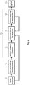
- Figure 4 shows an example of a completely digitally supported workflow from the planning of a control cabinet to the production of pre-assembled connection lines as well as the following method for the automated support of a connection process, for example a wiring process, including the detection of the connection line, the interpretation of the connection, the display of a corresponding user output, and ultimately as a result completed control cabinet.
- the Figure 4 shows in particular how the method described here and a system set up to carry out the method, such as system 2 or 32, can be inserted into such a workflow.
- a virtual model of the control cabinet to be manufactured is first generated by means of a computer program provided for this purpose, in that the virtual control cabinet is virtually equipped with the intended components and the connection lines required for connecting, in particular for wiring the individual components, in terms of their type and possibly also their laying routes are defined.
- the connection diagram for the system 2 or 32 is preferably also generated, which is later used to generate the user outputs for connecting the individual connecting lines.
- connection lines to be assembled are determined on the basis of the data model of the control cabinet generated in the first step 92 and produced on this database.
- the individual connecting lines are each provided with individual identifiers, for example by printing a numerical label or a barcode, by means of which the individual connecting lines can be clearly identified within the set of connecting lines made up for connecting the components to be arranged or arranged in the switch cabinet.
- step 96 an identifier of a pre-assembled connecting line for connecting, in particular the wiring, of components arranged in a switch cabinet is detected by means of a detection device.
- step 98 a visual user output is generated about the connection of the connection line identified via the recorded identifier.
- the visualization takes place on the basis of the previously recorded identifier specifically for the connection line identified in step 96 and depending on the connection diagram preferably generated in step 92 (see arrow from step 92 to step 98), which is available, for example, in the form of a virtual model of the control cabinet and information on the connection points and the route of the identified connection line.
- step 100 the user output generated in step 98 is output via an output device such as a screen or data glasses.
- the output is preferably carried out as an augmented reality representation so that the user can provide the work instructions required for the manual laying of the identified connection line, i.e. the connection points and the routing of the connection line concerned can be recorded intuitively and in spatial relation to the real control cabinet.
- Steps 96, 98 and 100 are repeated one after the other for the individual pre-assembled connection lines until finally, in step 104, as a result of the entire method, the switch cabinet with the completely connected, in particular wired, components arranged therein is completed.
- the user of the system can preferably confirm the connection of the respective connecting line in step 100 via an input device.
- This information is transmitted to the visualization device so that it can take into account the information about connecting lines that have already been laid when generating user outputs of subsequently identified connecting lines (cf. arrow from step 100 to step 98).
- the method for the automated support of a connection process of components arranged in a switch cabinet or on a mounting system, such as a mounting plate, can in particular also include preparatory steps 92 and 94, in which the connection diagram and the pre-assembled connection lines are generated.
- the entire method from step 92 to 104 represents an example of a method for connecting, in particular for wiring, of in a control cabinet or on a mounting system, e.g.
- a completely digitally supported workflow is created from the planning to the assembly of the connecting cables, their detection and interpretation to the connection of the connecting cables to the components in the real control cabinet or the assembly system, e.g. a mounting plate.
- FIG. 5 shows an embodiment of a detection unit not belonging to the invention for detecting an identifier 40 'of a connecting line 38'.
- the detection unit 110 comprises a receptacle 112 into which a connecting line 38 ′ to be identified can be inserted.
- a camera module 114 is arranged, with which image data can be captured from a connecting line 38 ′ inserted in the receptacle 112.
- the receptacle 112 is designed in the form of a channel-shaped cavity that is open on both sides, so that the connecting line 38 ′ can be pushed into the receptacle 112. Since the receptacle 112 is open on both sides, the connecting line 38 'can be pushed into the receptacle 112 until the identifier 40' of the connecting line 38 'can be detected by the camera module 114. As a result, the identifier 40 'can be recorded independently of its position on the connecting line 38'.
- the receptacle 112 can also only be opened on one side, in particular if the identifier 40 'is at a predetermined position of the connecting line 38' is provided, for example at a certain distance from one end of the connecting line 38 '.
- the depth of the receptacle 112 is then preferably adapted so that the identifier 40 ′ is arranged in the field of vision of the camera module 114 when the connecting line 38 ′ is pushed into the receptacle 112 as far as it will go.
- the receptacle 112 preferably has an expression in the form of an edge and the camera module 114 is preferably arranged such that the edge lies in the field of view of the camera module 114.
- the receptacle 112 can have a triangular cross section or be prism-shaped, with a corner of the triangle or an edge of the prism shape lying in the field of view of the camera module 114.
- a defined contact point for the connecting line 38 ′ is predetermined by the edge, whereby the positioning of the connecting line 38 ′ in the receptacle and the identifier 40 ′ in the field of view of the camera module 114 is facilitated.
- the detection unit 110 also has an illumination device 116 with which the receptacle 112 in the area of the camera module 114 can be illuminated so that the identifier 40 ′ can be reliably detected independently of the external light conditions.
- the lighting device 116 preferably extends transversely to the longitudinal extent of the receptacle 112 in such a way that at least 180 ° of the curved surface of a connecting line arranged in the receptacle 112 is illuminated so that the identifier printed on the curved surface of a connecting line can be reliably detected.
- the acquisition unit can optionally have a screen 138 on which the image acquired by the camera module 114 is output in order to make it easier for the technician to position the connecting line 38 ′ in the receptacle 112. In particular, the technician can thereby position the identifier 40 ′ more easily in the field of view of the camera module 114.
- the acquisition unit 110 also has a control device 118 which is set up to find an identifier 40 'of a connecting line 38' in the acquired image data and to generate a digital code for the identifier found.
- the control device 118 can also control the function of the camera module 114 and the lighting device 116.
- the detection unit 110 has a transmission device 120 which is set up to transmit the digital code for the identifier 40 'found to a visualization device for generating a user output by connecting the connection line identified by the identifier.
- the transmission device 120 is set up in the present case to transmit the digital code for the identifier 40 ′ to a server 130 which has a control device 132 on which a computer program for generating a visual user output runs as a function of the digital code.
- the transmission device 120 in the detection unit 110 is formed on the one hand by a network interface 122, for example a LAN or WLAN interface, and by a part of the computer program running on the control device 118 that enables the transmission of the digital code for the identifier via the network interface 122 and a network 142 to the server 130.
- a network interface 122 for example a LAN or WLAN interface
- the control device 118 that enables the transmission of the digital code for the identifier via the network interface 122 and a network 142 to the server 130.
- the server 130 which has a corresponding network interface 134 for receiving the digital code, can then use the transmitted digital code for the identifier 40 'and a connection diagram stored in a memory of the server 130, which for example contains a virtual model of the control cabinet with the therein arranged components to be connected can generate a user output by connecting the connecting line 38 'identified by means of the identifier 40'.
- the generated user output can then be output on a screen 136 of the server 130.
- the user output can also be output via data glasses that are coupled to the server 130 or to the acquisition unit 110 via a wired or wireless communication link.
- the generated user output is transmitted from the server 130 to the acquisition unit 110 and output via an optionally provided screen 138 of the acquisition unit 110.
- the acquisition unit 110 and the server 130 together form a system 144 for the automated support of a connection process in a switch cabinet or on a mounting system, e.g. a mounting plate, arranged components.
- the user output can also be generated in the acquisition unit 110 itself.
- the control device 118 can be set up to generate a user output depending on the generated code for the identifier 40 'and a connection diagram stored in a memory of the control device 118 and e.g. to be output via the screen 138 of the acquisition unit 110 or via data glasses connected to it by means of a communication link.
- the control device 118 represents the visualization device with part of the computer program running on it to generate the user output.
- the transmission of the digital code to the visualization device takes place in this case purely on the software side, the control device and a corresponding program part representing the transmission device.
- the detection unit 110 is designed as a stationary device that can be set up on site near the switch cabinet to be connected.
- the detection unit 110 preferably comprises a suitable housing 140 in which the individual components of the detection unit 110 are accommodated.
Description
Die Erfindung betrifft ein Verfahren mit den Merkmalen des Oberbegriffs des Anspruchs 1. Weiterhin betrifft die Erfindung ein System mit den Merkmalen des Oberbegriffs des Anspruchs 5, insbesondere zur Durchführung des zuvor beschriebenen Verfahrens. Die Erfindung betrifft zudem die Verwendung des Systems sowie ein Computerprogramm. Ein derartiges Verfahren und System ist aus der
Schaltschränke dienen vor allem zur Versorgung von Anlagen oder Elektroinstallationen mit elektrischer Energie und zum Teil auch mit Signalen, zum Beispiel zur Steuerung einer Anlage oder elektrotechnischer Komponenten. Zu diesem Zweck sind in einem Schaltschrank typischerweise eine Vielzahl elektrischer, elektronischer und zum Teil auch pneumatischer oder hydraulischer Komponenten untergebracht. Darüber hinaus können in bzw. an einem Schaltschrank auch weitere elektrische und elektronische Komponenten verbaut sein, die zum Beispiel zur Klimatisierung, zur Beleuchtung oder zur Überwachung des Schaltschranks dienen.Control cabinets are primarily used to supply systems or electrical installations with electrical energy and sometimes also with signals, for example to control a system or electrical components. For this purpose, a large number of electrical, electronic and sometimes also pneumatic or hydraulic components are typically housed in a switch cabinet. In addition, further electrical and electronic components can also be installed in or on a switch cabinet, which are used, for example, for air conditioning, lighting or for monitoring the switch cabinet.
Für eine ordnungsgemäße Funktionsweise müssen die im Schaltschrank untergebrachten Komponenten entsprechend eines vorgegebenen Anschlussplans, beispielsweise eines Verdrahtungsplans, eines Verschlauchungsplans, eines Verrohrungsplans oder einer Kombination daraus, über Verbindungsleitungen miteinander verbunden werden, wobei sich die Anforderungen an die einzelnen Verbindungsleitung je nach Art der Verbindung unterscheiden können, beispielsweise weil die Leitungen für unterschiedliche Stromstärken, Betriebsfrequenzen, Querschnitte oder für die Übermittlung von Daten ausgelegt sein müssen. Verdrahtungspläne dienen insbesondere zum Anschließen elektrotechnischer Komponenten; Verschlauchungs- und Verrohrungspläne dienen insbesondere zum Anschließen von pneumatischen bzw. hydraulischen Komponenten.For proper functioning, the components housed in the control cabinet must be connected to one another via connecting lines in accordance with a specified connection plan, for example a wiring plan, a tubing plan, a piping plan or a combination thereof, whereby the requirements for the individual Connection line can differ depending on the type of connection, for example because the lines must be designed for different currents, operating frequencies, cross-sections or for the transmission of data. Wiring diagrams are used in particular to connect electrical components; Hose and piping plans are used in particular to connect pneumatic or hydraulic components.
Die Bestückung eines Schaltschranks mit den entsprechenden Komponenten kann bereits werksseitig erfolgen oder auch direkt am Einsatzort. Das Anschließen, insbesondere die Verdrahtung der Komponenten kann ebenfalls werksseitig oder direkt am Einsatzort erfolgen und wird manuell von einem Techniker durchgeführt. Auch die Erweiterung oder Modifikation bestehender Schaltschränke erfordert eine manuelle Verdrahtung, Verschlauchung bzw. Verrohrung durch einen Techniker, insbesondere einen Elektrotechniker, wenn eine werksseitige, ggf. automatisierte Verdrahtung, Verschlauchung bzw. Verrohrung in solchen Fällen nicht möglich ist.A control cabinet can be fitted with the corresponding components at the factory or directly on site. The connection, in particular the wiring of the components, can also be carried out at the factory or directly on site and is carried out manually by a technician. The expansion or modification of existing control cabinets also requires manual wiring, tubing or piping by a technician, in particular an electrical engineer, if factory, possibly automated wiring, tubing or piping is not possible in such cases.
Bei der manuellen Verdrahtung/Verschlauchung/Verrohrung von Schaltschränken und Montagesystemen für Schaltschränke, wie zum Beispiel Montageplatten, gibt es verschiedene Verfahrensweisen.There are different procedures for the manual wiring / tubing / piping of control cabinets and mounting systems for control cabinets, such as mounting plates.
Der die Verdrahtung/Verschlauchung/Verrohrung ausführende Techniker kann zum Beispiel anhand der Angaben in einem vorgegebenen Stromlaufplan und mit seinem Knowhow selbst die einzelnen vorzunehmenden Verbindungen ermitteln, die zugehörigen Anschlusspunkte im Schaltschrank lokalisieren, für die einzelnen Verbindungen geeignete Verbindungsleitungen, insbesondere mit geeigneten Querschnitten bzw. aus geeigneten Materialien, auswählen und damit die Verdrahtung/Verschlauchung/Verrohrung durchführen.The technician performing the wiring / tubing / piping can, for example, use the information in a given circuit diagram and his know-how to determine the individual connections to be made, localize the associated connection points in the control cabinet, and use suitable connection lines for the individual connections, in particular with suitable cross-sections or from suitable materials and use them to carry out the wiring / tubing / piping.
Alternativ kann der Techniker auch nach einer sogenannten Verdrahtungs-, Verschlauchungs- und/oder Verrohrungsliste vorgehen, in denen die vorzunehmenden Verdrahtungen/Verschlauchungen/Verrohrungen bereits vorgegeben und aufgelistet sind. Der Techniker kann die in der Verdrahtungs-, Verschlauchungs- und/oder Verrohrungsliste aufgeführten Verbindungen dann nacheinander abarbeiten, indem er mit seinem Knowhow die jeweiligen Anschlusspunkte der einzelnen Verdrahtungen manuell lokalisiert, Verlegewege festlegt, und dann die Verdrahtung/Verschlauchung/Verrohrung entsprechend durchführt.Alternatively, the technician can also proceed according to a so-called wiring, tubing and / or tubing list, in which the wiring / tubing / tubing to be carried out already exists are specified and listed. The technician can then work through the connections listed in the wiring, tubing and / or tubing list one after the other by using his know-how to manually locate the respective connection points of the individual wirings, determine the routing paths, and then carry out the wiring / tubing / tubing accordingly.
Weiterhin gibt es verschiedene Verfahrensweisen zur Herstellung der zur Verdrahtung/Verschlauchung/Verrohrung erforderlichen Verbindungsleitungen:
So kann der Techniker mit seinem Knowhow die für die einzelnen Verbindungen jeweils erforderliche Verbindungsleitungsart selbst auswählen und vor Ort während des Anschlussvorgangs entsprechende Verbindungsleitungen selbst herstellen (konfektionieren). Für die Herstellung der Verbindungsleitungen kann er insbesondere die Verbindungsleitungen ablängen und endkonfektionieren, beispielsweise Aderendbehandlungen und/oder Beschriftungen aufbringen.There are also various methods of manufacturing the connecting lines required for wiring / tubing / piping:
In this way, the technician can use his know-how to select the type of connection cable required for the individual connections himself and produce (assemble) the corresponding connection cables himself on site during the connection process. To produce the connecting lines, he can in particular cut the connecting lines to length and assemble them, for example, apply wire end treatments and / or labels.
Alternativ können die Verbindungsleitungen auch automatisiert oder manuell vorab definiert und vorkonfektioniert werden, bevor der Techniker die Verdrahtung/Verrohrung/Verschlauchung vornimmt. Zu diesem Zweck kann beispielsweise während der Arbeitsvorbereitung vor dem eigentlichen Verdrahten/Verrohren/Verschlauchen ein sogenanntes virtuelles Routing durchgeführt werden, bei dem die Verdrahtung/Verschlauchung/Verrohrung des Schaltschranks, vorzugsweise softwaregestützt, bereits im Detail vorgeplant wird, so dass jede Verbindungsleitung mit Länge, Art der Verbindung, Art der Konfektionierung und ggf. Art der Beschriftung vorab definiert wird. Insbesondere können bei einem solchen virtuellen Routing auch bereits die Verlegewege vorab fix definiert und ggf. in einem Datenformat (wie zum Beispiel in einem CAx-Format) hinterlegt werden.Alternatively, the connecting lines can also be automatically or manually defined and pre-assembled in advance before the technician carries out the wiring / piping / tubing. For this purpose, a so-called virtual routing can be carried out during the work preparation prior to the actual wiring / tubing / tubing, in which the wiring / tubing / tubing of the control cabinet is planned in advance, preferably with software support, so that each connecting line has a length, The type of connection, type of assembly and, if applicable, type of labeling is defined in advance. In particular, with such a virtual routing, the laying routes can already be defined in advance and, if necessary, stored in a data format (such as a CAx format).
Durch die Vorkonfektionierung der Verbindungsleitung und Vorabdefinition der Verlegewege wird die Verdrahtung/Verschlauchung/Verrohrung eines Schaltschranks bereits deutlich vereinfacht, da der Techniker die Verbindungsleitungsart nicht selbst auswählen, die Verbindungsleitungen nicht selbst konfektionieren und vorzugsweise auch die Verlegewege nicht selbst bestimmen muss.By pre-assembling the connection line and defining the laying paths in advance, the wiring / tubing / piping of a control cabinet is already significantly simplified, since the technician does not have to select the type of connection line himself, does not have to assemble the connection lines himself and preferably does not have to determine the laying paths himself.
Aufgrund der Komplexität heutiger Schaltschränke und der Vielzahl innerhalb der Schaltschränke vorzunehmender Verbindungen besteht jedoch auch bei vorkonfektionierten Verbindungsleitungen für den Techniker das Problem, die einzelnen vorkonfektionierten Verbindungsleitungen korrekt zu identifizieren, die zu verbindenden Komponenten zu lokalisieren, die für die Verbindungsleitungen vorgesehenen Anschlusspunkte auf den Komponenten zu identifizieren, den jeweiligen Verlegeweg zu bestimmen und die Verbindungsleitung dann wie vorgesehen auch real zu verlegen und anzuschließen. Gerade bei komplexen Schaltschränken mit vielen Komponenten und Verbindungen kommt es immer wieder zu Verwechslungen, so dass der Techniker die Verlegung nicht ordnungsgemäß fertigstellen kann oder falsche Verbindungen durchgeführt werden, die zu einer fehlerhaften Funktion oder sogar zu einer Beschädigung von Komponenten im Betrieb führen können.Due to the complexity of today's control cabinets and the large number of connections to be made within the control cabinets, however, even with pre-assembled connection lines, the technician faces the problem of correctly identifying the individual pre-assembled connection lines, locating the components to be connected, and locating the connection points provided for the connection lines on the components identify, determine the respective laying route and then actually lay and connect the connection line as intended. Especially in the case of complex control cabinets with many components and connections, mix-ups occur again and again, so that the technician cannot complete the installation properly or incorrect connections are made, which can lead to incorrect functioning or even damage to components during operation.
Vor diesem Hintergrund liegt der vorliegenden Erfindung die Aufgabe zugrunde, ein Verfahren und ein System zur Verfügung zu stellen, mit dem insbesondere ein solcher Verdrahtungsvorgang effektiv unterstützt werden kann, so dass die Verdrahtung für den Techniker erleichtert wird, Fehlverdrahtungen vermieden werden und der Verdrahtungsprozess insgesamt bei erhöhter Qualität beschleunigt wird.Against this background, the present invention is based on the object of providing a method and a system with which in particular such a wiring process can be effectively supported, so that the wiring is made easier for the technician, incorrect wiring is avoided and the wiring process as a whole contributes increased quality is accelerated.
Diese Aufgabe wird erfindungsgemäß gelöst durch ein Verfahren, dadurch gekennzeichnet, dass das Erzeugen der visuellen Nutzerausgabe das Erzeugen einer grafischen Darstellung der Anschlusspunkte und des Verlegewegs der Verbindungsleitung aufweistAccording to the invention, this object is achieved by a method, characterized in that the generation of the visual user output includes the generation of a graphic representation of the connection points and the route of the connection line
Die oben genannte Aufgabe wird weiterhin erfindungsgemäß gelöst durch ein System, dadurch gekennzeichnet, dass die visuelle Nutzerausgabe (20, 70) eine grafische Darstellung der Anschlusspunkte und des Verlegewegs der Verbindungsleitung (12, 38, 38', 52) aufweistThe above-mentioned object is also achieved according to the invention by a system, characterized in that the visual user output (20, 70) has a graphical representation of the connection points and the route of the connecting line (12, 38, 38 ', 52)
Das zuvor beschriebene Verfahren wird vorzugsweise unter Verwendung eines solchen Systems durchgeführt. Entsprechend wird ein solches System vorzugsweise zur Durchführung des zuvor beschriebenen Verfahrens verwendet.The method described above is preferably carried out using such a system. Accordingly, such a system is preferably used to carry out the method described above.
Das zuvor beschriebene Verfahren und das zuvor beschriebene System dienen jeweils zur automatisierten Unterstützung eines Anschlussvorgangs. Unter einem Anschlussvorgang bzw. dem Anschließen von in einem Schaltschrank bzw. an einem Montagesystem angeordneten Komponenten wird vorliegend das Anschließen von Verbindungsleitungen an bzw. zwischen den Komponenten verstanden, die in einem Schaltschrank bzw. an einem Montagesystem, beispielsweise einer Montageplatte, angeordnet sind. Das Montagesystem kann in einem Schaltschrank angeordnet oder für einen solchen bestimmt sein. Alternativ kann es sich auch um ein unabhängiges Montagesystem handeln, dass auch ohne Schaltschrank verwendet werden kann, beispielsweise direkt an einer Maschine.The method described above and the system described above each serve to automatically support a connection process. In the present case, a connection process or the connection of components arranged in a switch cabinet or on an assembly system is the connection of Understood connecting lines on or between the components that are arranged in a switch cabinet or on a mounting system, for example a mounting plate. The mounting system can be arranged in a control cabinet or be intended for such. Alternatively, it can be an independent assembly system that can also be used without a control cabinet, for example directly on a machine.
Bei dem Anschlussvorgang kann es sich insbesondere um einen Verdrahtungsvorgang handeln, bei dem Verbindungsleitungen für die Verdrahtung wie zum Beispiel Einzeldrähte oder Kabel angeschlossen werden. Es ist aber auch denkbar, dass Verbindungsleitungen für pneumatische oder hydraulische Komponenten, zum Beispiel Schläuche, oder Rohre angeschlossen werden. Beim Anschluss von Schläuchen kann entsprechend von einem Verschlauchungsvorgang und beim Anschluss von Rohren von einem Verrohrungsvorgang gesprochen werden. Grundsätzlich umfasst der Begriff Anschlussvorgang damit Verdrahtungsvorgänge, Verschlauchungsvorgänge, Verrohrungsvorgänge und auch Kombinationen daraus. Der Anschlussvorgang selbst wird zwar manuell von einem Techniker durchgeführt; durch das zuvor beschriebene Verfahren bzw. System wird er hierbei jedoch automatisiert unterstützt. Insbesondere helfen ihm das Verfahren und das System dabei, die vorkonfektionierten Verbindungsleitungen eindeutig zuzuordnen, die zugehörigen Anschlusspunkte zu identifizieren und vorzugsweise auch einen vorgegebenen Verlegeweg einzuhalten, indem das Verfahren und das System dem Techniker die hierzu erforderlichen Informationen gezielt für die von ihm jeweils ausgewählte nächste Verbindungsleitung zur Verfügung stellt.The connection process can in particular be a wiring process in which connecting lines for the wiring, such as, for example, individual wires or cables, are connected. However, it is also conceivable that connection lines for pneumatic or hydraulic components, for example hoses or pipes, are connected. When connecting hoses, one can accordingly speak of a tubing process and when connecting pipes a tubing process. Basically, the term connection process thus includes wiring processes, tubing processes, piping processes and also combinations thereof. The connection process itself is carried out manually by a technician; however, he is supported automatically by the method or system described above. In particular, the method and the system help him to unambiguously assign the pre-assembled connection lines, to identify the associated connection points and preferably also to adhere to a specified routing path by providing the technician with the information required for this purpose for the next connection line selected by him provides.
Der Anschlussvorgang, insbesondere Verdrahtungsvorgang, erfolgt insbesondere ; in einem Schaltschrank oder an einer Montageplatte angeordneten Komponenten. Unter einem Schaltschrank wird vorliegend eine Einrichtung zur Unterbringung von elektrotechnischen, hydraulischen und/oder pneumatischen Komponenten verstanden. Der Schaltschrank bildet eine Einhausung zum Schutz der Komponenten, insbesondere vor äußeren Einflüssen und ggf. Einblicken, aufweist. Eine solche Einhausung ermöglicht zudem vorzugsweise eine gezielte Wärmeabfuhr von den darin installierten Komponenten. Zur Montage dieser Komponenten werden in der Regel Montagesysteme genutzt die als Montageplatten oder Montagerahmen bezeichnet werden und die in den Schaltschrank eingebaut werden. Auf diesen Montagesystemen werden die Komponenten mechanisch befestigt. Weiterhin können Montagesysteme auch unabhängig von einem Schaltschrank verwendet werden.The connection process, in particular the wiring process, takes place in particular; Components arranged in a control cabinet or on a mounting plate. In the present case, a switch cabinet is understood to mean a device for accommodating electrotechnical, hydraulic and / or pneumatic components. The switch cabinet forms an enclosure to protect the components, in particular from external influences and, if necessary, from being seen. Such an enclosure also preferably enables targeted heat dissipation from the components installed in it. To assemble these components, assembly systems are generally used which are known as assembly plates or assembly frames and which are built into the control cabinet. The components are mechanically fastened to these assembly systems. Furthermore, assembly systems can also be used independently of a control cabinet.
Der Schaltschrank weist vorzugsweise eine Schranktür auf, durch die das Innere des Gehäuses zugänglich ist, so dass die Montage und der Anschluss der Komponenten erfolgen können.The switch cabinet preferably has a cabinet door through which the interior of the housing is accessible so that the components can be assembled and connected.
Bei den Komponenten handelt es sich insbesondere um Komponenten der Steuerungstechnik. Speziell kann es sich bei dem Schaltschrank um einen Schaltschrank für elektrotechnische Komponenten und ggf. zusätzlich hydraulische und/oder pneumatische Komponenten handeln. Der Schaltschrank kann jedoch auch ausschließlich für hydraulische und/oder pneumatische Komponenten vorgesehen sein.The components are, in particular, control technology components. In particular, the switch cabinet can be a switch cabinet for electrotechnical components and possibly additional hydraulic and / or pneumatic components. However, the switch cabinet can also be provided exclusively for hydraulic and / or pneumatic components.
Unter einem Montagesystem werden Systeme verstanden, die dazu dienen, um Komponenten in einem Schaltschrank oder auch unabhängig davon zu installieren. Bei dem Montagesystem kann es sich beispielsweise um einen Montagerahmen oder um eine Montageplatte handeln. Unter einer Montageplatte wird eine Platte verstanden, die zur Anordnung und mechanischen Befestigung innerhalb eines Schaltschranks dient. Die auf einer Montageplatte angeordneten Komponenten werden anschließend über geeignete elektrotechnische, pneumatische oder hydraulische Verbindungen miteinander verbunden. Zum Zweck der Montage weist die Montageplatte vorzugsweise Montagemittel wie zum Beispiel Bohrungen oder Schienen auf, an denen die elektrischen und elektronischen Komponenten montiert werden können. Insbesondere kann eine solche Montageplatte einen Teil eines Schaltschranks bilden.An assembly system is understood to mean systems that are used to install components in a control cabinet or independently of it. The mounting system can be, for example, a mounting frame or a mounting plate. A mounting plate is understood to be a plate that is used for the arrangement and mechanical fastening within a control cabinet. The components arranged on a mounting plate are then connected to one another via suitable electrical, pneumatic or hydraulic connections. For the purpose of mounting, the mounting plate preferably has mounting means such as bores or rails, on which the electrical and electronic components can be mounted. In particular, such a mounting plate can form part of a control cabinet.
Bei dem Verfahren wird mittels einer Erfassungseinrichtung eine Kennung einer Verbindungsleitung erfasst. Die Erfassung der Kennung erfolgt vorzugsweise optisch, beispielsweise mittels einer Kamera oder mittels eines Scanners, zum Beispiel eines Laserscanners. Entsprechend weist die Erfassungseinrichtung des Systems vorzugsweise eine Kamera oder einen Scanner, beispielsweise einen Laserscanner, auf. Die Kennung kann zum Beispiel einfach auf eine Verbindungsleitung aufgedruckt werden, wodurch die Herstellung der Kennung sehr einfach und kostengünstig bewirkt werden kann.In the method, an identifier of a connecting line is detected by means of a detection device. The identification is preferably detected optically, for example by means of a camera or by means of a scanner, for example a laser scanner. Accordingly, the detection device of the system preferably has a camera or a scanner, for example a laser scanner. The identifier can, for example, simply be printed on a connecting line, as a result of which the identifier can be produced very easily and inexpensively.
Unter einer Kennung einer Verbindungsleitung wird eine Kennung verstanden, die einer bestimmten Verbindungsleitung zugeordnet ist. Die Kennung ist vorzugsweise direkt an der Verbindungsleitung angebracht, beispielsweise auf diese aufgedruckt. Bei der Kennung kann es sich beispielsweise um einen Barcode oder QR-Code handeln. Alternativ kann die Kennung auch eine Zeichenfolge sein, zum Beispiel aus Zahlen, Buchstaben und/oder anderen Symbolen, die von der Erfassungseinrichtung erfasst und zum Beispiel durch ein an sich bekanntes Bildanalyseverfahren erkannt werden kann. Beispielsweise kann die Kennung ein numerischer oder alphanumerischer Code, ggf. auch mit Sonderzeichen, sein.An identifier of a connecting line is understood to mean an identifier that is assigned to a specific connecting line. The identifier is preferably attached directly to the connecting line, for example printed on it. The identifier can be a barcode or QR code, for example. Alternatively, the identifier can also be a character sequence, for example made up of numbers, letters and / or other symbols, which can be recorded by the detection device and recognized, for example, by an image analysis method known per se. For example, the identifier can be a numeric or alphanumeric code, possibly also with special characters.
Die Kennung identifiziert die Verbindungsleitung. Das bedeutet, dass sich die Verbindungsleitung anhand der Kennung von anderen Verbindungsleitungen unterscheiden lässt. Vorzugsweise ist die Kennung so gewählt, dass sie die Verbindungsleitung innerhalb einer Menge von mehreren Verbindungsleitungen zum Anschließen, insbesondere zur Verdrahtung, von in einem Schaltschrank bzw. an einem Montagesystem, z.B. einer Montageplatte, angeordneter Komponenten eindeutig identifiziert. Sind zum Anschließen, insbesondere zur Verdrahtung, von in einem Schaltschrank bzw. an einem Montagesystem, z.B. einer Montageplatte, angeordneten Komponenten eine Menge Verbindungsleitungen vorgesehen, so unterscheiden sich also die Kennungen der einzelnen Verbindungsleitungen vorzugsweise voneinander, so dass sich jede einzelne Verbindungsleitung anhand ihrer Kennung eindeutig identifizieren lässt. Umfasst die Menge an Verbindungsleitungen zum Anschließen, insbesondere zur Verdrahtung von in einem Schaltschrank bzw. an einem Montagesystem, z.B. einer Montageplatte, angeordneter Komponenten mehrere Verbindungsleitungen gleicher Art und Länge, so können diese in einer Ausführungsform auch gleiche bzw. in Teilen gleiche Kennungen aufweisen.The identifier identifies the connection line. This means that the connection line can be distinguished from other connection lines by means of the identifier. The identifier is preferably selected such that it uniquely identifies the connection line within a set of several connection lines for connecting, in particular for wiring, components arranged in a switch cabinet or on a mounting system, for example a mounting plate. If a number of connecting lines are provided for connecting, in particular for wiring, components arranged in a switch cabinet or on a mounting system, e.g. a mounting plate, the identifiers of the individual connecting lines preferably differ from one another, so that each individual connecting line can be identified by its identifier can be clearly identified. Includes the crowd Connecting lines for connecting, in particular for wiring components arranged in a control cabinet or on a mounting system, eg a mounting plate, several connecting lines of the same type and length, so in one embodiment they can also have identical or partially identical identifiers.
Bei dem Verfahren wird abhängig von der erfassten Kennung und einem Anschlussplan eine visuelle Nutzerausgabe über das Anschließen der durch die Kennung identifizierten Verbindungsleitung erzeugt. Entsprechend ist die Visualisierungseinrichtung des Systems dazu eingerichtet, abhängig von der erfassten Kennung und einem Anschlussplan eine visuelle Nutzerausgabe über das Anschließen der durch die Kennung identifizierten Verbindungsleitung zu erzeugen. Bei dem Anschlussplan kann es sich beispielsweise um einen Verdrahtungsplan handeln und die Visualisierungseinrichtung kann entsprechend dazu eingerichtet sein, abhängig von der erfassten Kennung dem Verdrahtungsplan eine visuelle Nutzerausgabe über die Verdrahtung der durch die Kennung identifizierten Verbindungsleitung zu erzeugen.In the method, a visual user output about the connection of the connection line identified by the identifier is generated depending on the detected identifier and a connection diagram. Accordingly, the visualization device of the system is set up to generate a visual user output on the connection of the connection line identified by the identifier, depending on the detected identifier and a connection diagram. The connection diagram can be a wiring diagram, for example, and the visualization device can be set up accordingly to generate a visual user output via the wiring of the connection line identified by the identifier, depending on the detected identifier of the wiring plan.
Unter einer Nutzerausgabe über das Anschließen und die Verdrahtung, der durch die Kennung identifizierten Verbindungsleitung wird eine Nutzerausgabe verstanden, die Anweisungen zum Anschließen und zur Verdrahtung, der identifizierten Verbindungsleitung erhält. Die Anweisungen zum Anschließen und zur Verdrahtung, sind in grafischer Form, wobei die Nutzerausgabe eine grafische Darstellung der Anschlusspunkte der Verbindungsleitung und des Verlegewegs der Verbindungsleitung enthalt.A user output about the connection and the wiring of the connecting line identified by the identifier is understood to mean a user output that receives instructions for connecting and wiring the identified connecting line. The instructions for connecting and wiring are in graphic form, with the user output containing a graphic representation of the connection points of the connection line and the route of the connection line.
Zur Erzeugung der Nutzerausgabe wird vorzugsweise eine Visualisierungssoftware eingesetzt, die zum Beispiel auf einem Speicher des Systems gespeichert sein und auf mindestens einem Prozessor der Visualisierungseinrichtung ausgeführt werden kann. Auf einem Speicher des Systems kann insbesondere auch ein virtuelles Modell des Schaltschranks mit den darin angeordneten, anzuschließenden Komponenten bzw. des Montagesystems mit den daran angeordneten, anzuschließenden Komponenten gespeichert sein, auf dessen Grundlage die Visualisierungssoftware die visuelle Nutzerausgabe erzeugt.To generate the user output, visualization software is preferably used, which, for example, can be stored in a memory of the system and can be executed on at least one processor of the visualization device. In particular, a virtual model of the Switch cabinet with the components to be connected arranged therein or the assembly system with the components to be connected arranged thereon, on the basis of which the visualization software generates the visual user output.
Die Nutzerausgabe über das Anschließen, insbesondere über die Verdrahtung, wird abhängig von der erfassten Kennung erzeugt. Auf diese Weise kann die Nutzerausgabe gezielt an die durch die Kennung identifizierte Verbindungsleitung angepasst werden, so dass der Nutzer gezielt die Anweisungen zum Anschließen, insbesondere zur Verdrahtung, der von ihm ausgewählten Verbindungsleitung erhält.The user output about the connection, in particular about the wiring, is generated as a function of the detected identifier. In this way, the user output can be specifically adapted to the connection line identified by the identifier, so that the user specifically receives the instructions for connecting, in particular for wiring, the connection line selected by him.
Die Nutzerausgabe wird weiterhin abhängig von einem Anschlussplan erzeugt. Unter einem Anschlussplan wird ein Plan verstanden, der den einzelnen Verbindungsleitungen Informationen für deren Anschluss zuordnet, insbesondere die Anschlusspunkte der jeweiligen Verbindungsleitung und den Verlegeweg der jeweiligen Verbindungsleitung. Der Anschlussplan kann beispielsweise auf einem Speicher des Systems gespeichert sein, so dass er von der Visualisierungseinrichtung abgerufen werden kann. Bei dem Anschlussplan kann es sich insbesondere um einen Verdrahtungsplan handeln, der den einzelnen Verbindungsleitungen Informationen für deren Verdrahtung zuordnet. Weiterhin kann es sich bei dem Anschlussplan auch um einen Verschlauchungsplan und/oder einen Verrohrungsplan handeln, der den einzelnen Verbindungsleitungen Informationen für deren Verbindung, insbesondere durch Schläuche und/oder Rohre, zuordnet. Der Anschlussplan kann auch eine Kombination aus einem Verdrahtungsplan, einem Verschlauchungsplan und/oder einem Verrohrungsplan sein.The user output is still generated depending on a connection diagram. A connection plan is understood to mean a plan which assigns information for their connection to the individual connecting lines, in particular the connection points of the respective connecting line and the route of the respective connecting line. The connection diagram can for example be stored on a memory of the system so that it can be called up by the visualization device. The connection diagram can in particular be a wiring diagram that assigns information for their wiring to the individual connecting lines. Furthermore, the connection plan can also be a tubing plan and / or a piping plan that assigns information to the individual connecting lines for their connection, in particular by means of hoses and / or pipes. The connection plan can also be a combination of a wiring plan, a tubing plan and / or a piping plan.
Der Anschlussplan, insbesondere Verdrahtungsplan, kann zum Beispiel in Form eines virtuellen Modells, insbesondere eines zwei- oder dreidimensionalen Modells, des Schaltschranks bzw. der Montageplatte abgespeichert sein, das einerseits Informationen über den Schaltschrank (bzw. über die Montageplatte) und die darin (bzw. daran) angeordneten Komponenten und andererseits Informationen über die vorkonfektionierten Verbindungsleitungen zur Verbindung der einzelnen Komponenten umfasst, insbesondere die jeweiligen Anschlusspunkte und den jeweiligen Verlegeweg der Verbindungsleitungen.The connection diagram, in particular the wiring diagram, can be saved, for example, in the form of a virtual model, in particular a two- or three-dimensional model, of the control cabinet or the mounting plate, which on the one hand contains information about the control cabinet (or the mounting plate) and the information contained therein (or . Thereon) arranged components and on the other hand information about the Comprises pre-assembled connection lines for connecting the individual components, in particular the respective connection points and the respective laying path of the connection lines.
Die Nutzerausgabe wird über eine Ausgabeeinrichtung ausgegeben. Bei der Ausgabeeinrichtung handelt es sich vorzugsweise um einen Bildschirm, einen Projektor, eine Datenbrille oder auch um eine Kombination aus einem Bildschirm, einem Projektor und/oder einer Datenbrille. Bei der Ausgabeeinrichtung kann es sich insbesondere auch um einen Bildschirm eines mobilen Geräts, wie zum Beispiel eines 1Smartphones oder Tablet-Computers, handeln.The user output is output via an output device. The output device is preferably a screen, a projector, data glasses or a combination of a screen, a projector and / or data glasses. The output device can in particular also be a screen of a mobile device, such as a smartphone or tablet computer.
Mit dem beschriebenen Verfahren und dem beschriebenen System kann ein Techniker nach Auswahl einer Verbindungsleitung deren Kennung automatisiert erfassen lassen und dann anhand der über die Ausgabeeinrichtung ausgegebenen Nutzerausgabe die Installation der betreffenden Verbindungsleitung durchführen.With the method described and the system described, a technician can automatically record the identification of a connection line after selecting a connection line and then carry out the installation of the connection line in question using the user output output via the output device.
Beschrieben wird weiterhin eine nicht zur Erfindung gehörende Erfassungseinheit zum Erfassen einer Kennung einer Verbindungsleitung mit einem Erfassungsbereich, in dem eine zu identifizierende Verbindungsleitung positionierbar ist, mit einem Kameramodul, das dazu eingerichtet ist, Bilddaten von einer in dem Erfassungsbereich positionierten Verbindungsleitung zu erfassen, mit einer Steuereinrichtung, die dazu eingerichtet ist, in den erfassten Bilddaten eine Kennung einer Verbindungsleitung aufzufinden und einen digitalen Code für die aufgefundene Kennung zu erzeugen, und mit einer Übermittlungseinrichtung, die dazu eingerichtet ist, den digitalen Code für die aufgefundene Kennung an eine Visualisierungseinrichtung zur Erzeugung einer Nutzerausgabe über das Anschließen, insbesondere über die Verdrahtung, der durch die Kennung identifizierten Verbindungsleitung zu übertragen.Also described is a detection unit not belonging to the invention for detecting an identifier of a connection line with a detection area in which a connection line to be identified can be positioned, with a camera module which is set up to detect image data from a connection line positioned in the detection area, with a Control device which is set up to find an identifier of a connection line in the captured image data and to generate a digital code for the identifier found, and with a transmission device which is set up to send the digital code for the identifier found to a visualization device for generating a User output via the connection, in particular via the wiring, of the connection line identified by the identifier.
Der Erfassungsbereich umfasst vorzugsweise eine Aufnahme, in die eine zu identifizierende Verbindungsleitung eingelegt werden kann. In diesem Fall ist das Kameramodul vorzugsweise dazu eingerichtet, Bilddaten von einer in die Aufnahme eingelegten Verbindungsleitung zu erfassen. Die Aufnahme ist vorzugsweise so ausgestaltet, dass sie einen Abschnitt der Verbindungsleitung zumindest teilweise umgibt. Beispielsweise kann die Aufnahme in Form eines Kanals ausgebildet sein, in den die Verbindungsleitung einlegbar oder einschiebbar ist. Der Kanal kann beispielsweise ein- oder beidseitig geöffnet sein. Die Aufnahmevorrichtung ist vorzugsweise so dimensioniert, dass sie das Erfassen einer Kennung an verschiedenen Positionen auf der Verbindungsleitung ermöglicht, zum Beispiel am Drahtende, fortlaufend entlang des Drahts oder an einer bestimmten Stelle der Verbindungsleitung, zum Beispiel mit einem bestimmten Abstand zum Drahtende.The detection area preferably comprises a receptacle into which a connecting line to be identified can be inserted. In this case it is Camera module preferably set up to capture image data from a connecting line inserted into the receptacle. The receptacle is preferably designed such that it at least partially surrounds a section of the connecting line. For example, the receptacle can be designed in the form of a channel into which the connecting line can be inserted or pushed. The channel can, for example, be open on one or both sides. The receiving device is preferably dimensioned such that it enables the detection of an identifier at different positions on the connecting line, for example at the end of the wire, continuously along the wire or at a certain point on the connecting line, for example at a certain distance from the wire end.
Die Erfassungseinheit weist weiterhin ein Kameramodul auf, das dazu eingerichtet ist, Bilddaten von einer im Erfassungsbereich positionierten Verbindungsleitung, insbesondere einer in die vorzugsweise vorgesehene Aufnahme eingelegten Verbindungsleitung zu erfassen. Zu diesem Zweck ist das Kameramodul insbesondere im Bereich der Aufnahme angeordnet. Ist die Aufnahme beispielsweise in Form eines Kanals ausgebildet, so ist das Kameramodul vorzugsweise innerhalb des Kanals bzw. an der Kanalwandung angeordnet. Vorzugsweise weist die Aufnahme eine Ausprägung wie zum Beispiel eine Kante auf, die im Sichtfeld des Kameramoduls angeordnet ist. Auf diese Weise wird die Positionierung der Verbindungsleitung in der Aufnahme erleichtert, um die Kennung im Sichtfeld des Kameramoduls zu positionieren.The acquisition unit also has a camera module which is set up to acquire image data from a connection line positioned in the detection area, in particular a connection line inserted into the preferably provided receptacle. For this purpose, the camera module is arranged in particular in the area of the recording. If the receptacle is in the form of a channel, for example, then the camera module is preferably arranged within the channel or on the channel wall. The receptacle preferably has a characteristic such as, for example, an edge, which is arranged in the field of view of the camera module. In this way, the positioning of the connecting line in the receptacle is facilitated in order to position the identifier in the field of view of the camera module.
Weiterhin weist die Erfassungseinheit vorzugsweise einen Bildschirm auf, auf dem die vom Kameramodul erfassten Bilddaten ausgegeben werden. Dies erleichtert die Positionierung der Verbindungsleitung in der Aufnahme, so dass die Kennung vom Kameramodul erfasst werden kann.Furthermore, the acquisition unit preferably has a screen on which the image data acquired by the camera module are output. This makes it easier to position the connecting line in the receptacle so that the identifier can be detected by the camera module.
Um die Erfassung der Bilddaten möglichst unabhängig von sich verändernden Umgebungsbedingungen wie zum Beispiel der Lichtverhältnisse am Ort der Erfassungseinheit durchführen und die Kennung einer Verbindungsleitung sicher erkennen zu können, weist die Erfassungseinheit vorzugsweise eine Beleuchtungseinrichtung auf, die das Sichtfeld des Kameramoduls ausleuchtet. Ist die Aufnahme in Form eines Kanals ausgebildet, so ist die Beleuchtungseinrichtung vorzugsweise innerhalb des Kanals bzw. an der Kanalwandung angeordnet.In order to capture the image data as independently as possible of changing environmental conditions, such as the lighting conditions at the location of the capture unit, and to identify a connection line safely To be able to recognize, the detection unit preferably has an illumination device that illuminates the field of view of the camera module. If the receptacle is designed in the form of a channel, the lighting device is preferably arranged within the channel or on the channel wall.
Die Beleuchtungseinrichtung ist vorzugsweise derart ausgebildet und angeordnet, um eine gekrümmte Oberfläche auf einer Verbindungsleitung wie einem Kabel, einem Rohr oder einem Schlauch gleichmäßig auszuleuchten. Auf diese Weise kann eine auf die Verbindungsleitung gedruckte Kennung zuverlässig erfasst werden. Vorzugsweise ist die Beleuchtungseinrichtung derart ausgebildet und angeordnet, dass eine Verbindungsleitung quer zu ihrer Erstreckungsrichtung über einen Winkelbereich von mindestens 180°, vorzugsweise mindestens 270° gleichmäßig ausgeleuchtet werden kann. Insbesondere kann die Beleuchtungseinrichtung die vorzugsweise vorgesehene Aufnahme zumindest teilweise umgeben oder an mehreren Seiten der Aufnahme angeordnet sein.The lighting device is preferably designed and arranged to evenly illuminate a curved surface on a connecting line such as a cable, a pipe or a hose. In this way, an identifier printed on the connecting line can be reliably detected. The lighting device is preferably designed and arranged in such a way that a connecting line can be uniformly illuminated transversely to its direction of extension over an angular range of at least 180 °, preferably at least 270 °. In particular, the lighting device can at least partially surround the preferably provided receptacle or be arranged on several sides of the receptacle.
Die Erfassungseinheit weist weiterhin eine Steuereinrichtung auf, die dazu eingerichtet ist, in den erfassten Bilddaten eine Kennung einer Verbindungsleitung aufzufinden. Zu diesem Zweck kann die Steuereinrichtung insbesondere mindestens einen Prozessor und einen Speicher mit einem Programm zur Analyse von Bilddaten aufweisen, dessen Ausführung auf dem mindestens einen Prozessor eine Bildanalyse der von dem Kameramodul erfassten Bilddaten veranlasst, um in den Bilddaten eine Kennung einer Verbindungsleitung, beispielsweise eine Zeichenfolge wie einen numerischen Code oder einen Barcode bzw. QR-Code, aufzufinden.The acquisition unit also has a control device which is set up to find an identifier of a connection line in the acquired image data. For this purpose, the control device can in particular have at least one processor and a memory with a program for analyzing image data, the execution of which on the at least one processor triggers an image analysis of the image data captured by the camera module in order to include an identifier of a connection line, for example a Find a string of characters such as a numeric code or a barcode or QR code.
Die Steuereinrichtung ist weiterhin dazu eingerichtet, einen digitalen Code für die aufgefundene Kennung zu erzeugen. Enthalten die Bilddaten beispielsweise ein Bild einer Kennung in Form einer Zeichenfolge (z.B. Bilddaten der Zeichenfolge "A38BX") oder eines Bar- bzw. QR-Codes, so ist die Steuereinrichtung vorzugsweise dazu eingerichtet, eine digitale Repräsentation der Zeichenfolge (im Beispiel die digitale Zeichenfolge (String) "A38BX") oder der im Bar- bzw. QR-Code kodierten Nachricht zu erzeugen. Durch diese Umwandlung der Bilddaten in einen digitalen Code kann dieser digital weiterverarbeitet werden.The control device is also set up to generate a digital code for the identifier found. If the image data contains, for example, an image of an identifier in the form of a character string (e.g. image data of the character string "A38BX") or a bar or QR code, the control device is preferably set up to provide a digital representation of the character string (in the example the digital character string (String) "A38BX") or the message encoded in the bar or QR code produce. This conversion of the image data into a digital code enables it to be further processed digitally.
Die Erfassungseinheit weist weiterhin eine Übermittlungseinrichtung auf, die dazu eingerichtet ist, den digitalen Code für die aufgefundene Kennung an eine Visualisierungseinrichtung zur Erzeugung einer Nutzerausgabe über das Anschließen, insbesondere über die Verdrahtung, der durch die Kennung identifizierten Verbindungsleitung zu übertragen. Die Übermittlungseinrichtung kann beispielsweise eine Sendeeinrichtung umfassen, über die der digitale Code zum Beispiel über eine standardisierte Schnittstelle, wie eine Netzwerkschnittstelle, mit einem digitalen Übertragungsprotokoll an einen Server übermittelt werden kann, auf dem eine Visualisierungssoftware zur Erzeugung einer Nutzerausgabe über das Anschließen, insbesondere über die Verdrahtung, der durch die Kennung identifizierten Verbindungsleitung läuft.The detection unit also has a transmission device that is set up to transmit the digital code for the identifier found to a visualization device for generating a user output via the connection, in particular via the wiring, of the connection line identified by the identifier. The transmission device can include, for example, a transmission device via which the digital code can be transmitted to a server, for example via a standardized interface such as a network interface, with a digital transmission protocol on which visualization software for generating a user output can be connected, in particular via the Wiring of the connection line identified by the identifier.
In einer Ausführungsform ist in die Erfassungseinheit eine Visualisierungseinheit integriert, die dazu eingerichtet ist, eine Nutzerausgabe über das Anschließen, insbesondere die Verdrahtung, der durch die Kennung identifizierten Verbindungsleitung zu erzeugen. Auf diese Weise kann die Nutzerausgabe direkt in der Erfassungseinheit erzeugt und vorzugsweise auf einer Nutzerausgabeeinrichtung der Erfassungseinheit oder auf einer über eine Kommunikationsverbindung mit der Erfassungseinheit verbundenen Ausgabeeinheit, wie zum Beispiel einer Datenbrille o.ä. angezeigt werden. Die Übermittlung des digitalen Codes kann in diesem Fall insbesondere rein softwareseitig erfolgen, indem zum Beispiel eine Variable mit dem digitalen Code für die Kennung an ein Visualisierungsmodul übergeben wird.In one embodiment, a visualization unit is integrated into the detection unit, which is set up to generate a user output about the connection, in particular the wiring, of the connection line identified by the identifier. In this way, the user output can be generated directly in the registration unit and preferably on a user output device of the registration unit or on an output unit connected to the registration unit via a communication link, such as data glasses or the like. are displayed. In this case, the transmission of the digital code can take place purely in software, for example by transferring a variable with the digital code for the identifier to a visualization module.
Die Erfassungseinheit kann als stationäre oder mobile Einheit ausgebildet sein. Vorzugsweise umfasst die Erfassungseinheit eine Einhausung, die die einzelnen Komponenten der Erfassungseinheit vor Einflüssen aus der Umgebung wie zum Beispiel Staub, Nässe, Feuchtigkeit udgl. schützt. Die vorzugsweise vorgesehene Aufnahme kann insbesondere durch die Einhausung gebildet werden, wobei in die Einhausung dann vorzugsweise eine Beleuchtungseinrichtung integriert ist, um eine gekrümmte Oberfläche einer in der Aufnahme positionierten Verbindungsleitung gleichmäßig auszuleuchten.The detection unit can be designed as a stationary or mobile unit. The detection unit preferably comprises an enclosure that protects the individual components of the detection unit from environmental influences such as dust, moisture, moisture and the like. protects. The preferably provided receptacle can in particular be formed by the housing, in which Housing then preferably a lighting device is integrated in order to uniformly illuminate a curved surface of a connecting line positioned in the receptacle.
Die oben genannte Aufgabe wird erfindungsgemäß weiterhin gelöst durch die Verwendung des zuvor beschriebenen Systems zur automatisierten Unterstützung eines Anschlussvorgangs, insbesondere eines Verdrahtungsvorgangs von in einem Schaltschrank oder an einem Montagesystem, wie zum Beispiel einer Montageplatte, angeordneten Komponenten.The above-mentioned object is further achieved according to the invention by using the previously described system for automated support of a connection process, in particular a wiring process of components arranged in a switch cabinet or on a mounting system, such as a mounting plate.
Die oben genannte Aufgabe wird weiterhin gelöst durch ein Computerprogramm umfassend Befehle, die bei der Ausführung des Programms durch einen Computer diesen veranlassen, das zuvor beschriebene Verfahrens auszuführen. Ein solches Computerprogramm kann beispielsweise auf einem Speicher des System oder der Erfassungseinheit gespeichert werden, so dass es auf der jeweiligen Steuereinrichtung ausführbar ist.The above-mentioned object is also achieved by a computer program comprising commands which, when the program is executed by a computer, cause the computer to carry out the method described above. Such a computer program can be stored, for example, in a memory of the system or of the acquisition unit so that it can be executed on the respective control device.
Im Folgenden werden verschiedene Ausführungsformen des Verfahrens, des Systems, des Computerprogramms und der Verwendung beschrieben, wobei die einzelnen Ausführungsformen jeweils einzeln für das Verfahren, das System, das Computerprogramm und die Verwendung gelten und wobei die einzelnen Ausführungsformen zudem miteinander kombiniert werden können.In the following, various embodiments of the method, the system, the computer program and the use are described, the individual embodiments each individually applying to the method, the system, the computer program and the use, and the individual embodiments also being able to be combined with one another.
Dadurch dass dem Techniker zum Anschließen, insbesondere zur Verdrahtung, von in einem Schaltschranks bzw. an einem Montagesystem, z.B. einer Montageplatte, angeordneten Komponenten eine Menge vorkonfektionierter Verbindungsleitungen zur Verfügung steht, wird das Anschließen, insbesondere die Verdrahtung, der in dem Schaltschrank bzw. an der Montageplatte angeordneten Komponenten deutlich vereinfacht, da der Techniker nicht selbst Art und Länge der einzelnen Verbindungsleitungen bestimmen und herstellen muss. Durch das hier beschriebene Verfahren und System wird zudem das bisherige Problem aus dem Stand der Technik überwunden, dass bei einer großen Menge vorkonfektionierter Verbindungsleitungen zum Anschließen, insbesondere zur Verdrahtung von in einem Schaltschrank bzw. an einem Montagesystem, z.B. einer Montageplatte, angeordneten Komponenten der Techniker nur schwierig die einzelnen Verbindungsleitungen auseinanderhalten kann. Indem das Verfahren und das System dazu eingerichtet sind, das Anschließen, insbesondere die Verdrahtung, von in einem Schaltschrank bzw. an einem Montagesystem, z.B. einer Montageplatte, angeordneten Komponenten mit vorkonfektionierten Verbindungsleitungen zu unterstützen, indem sie dem Techniker die zum Anschließen, insbesondere zur Verdrahtung, der einzelnen Verbindungsleitungen erforderlichen Informationen auf Abruf gezielt zur Verfügung stellen, kann der Techniker das Anschließen, insbesondere die Verdrahtung, der in dem Schaltschrank bzw. an der Montageplatte angeordneten Komponenten viel einfacher durchführen.Because the technician is required to connect, in particular for wiring, in a control cabinet or on a mounting system, e.g. If a number of pre-assembled connection lines are available on a mounting plate, arranged components, the connection, in particular the wiring, of the components arranged in the control cabinet or on the mounting plate is significantly simplified, since the technician does not have to determine and manufacture the type and length of the individual connection lines himself . The method and system described here also overcome the previous problem from the prior art that with a large number of pre-assembled connection lines for connection, in particular for wiring in a control cabinet or on an assembly system, e.g. a mounting plate, arranged components the technician can only with difficulty distinguish the individual connecting lines. In that the method and the system are set up to facilitate the connection, in particular the wiring, of in a control cabinet or on a mounting system, e.g. a mounting plate, to support arranged components with pre-assembled connecting lines by providing the technician with the information required for connecting, in particular for wiring, the individual connecting lines on request, the technician can do the connection, in particular the wiring that is in the control cabinet or . perform components arranged on the mounting plate much more easily.
Die Visualisierungseinrichtung ist vorzugsweise dazu eingerichtet, visuelle Nutzerausgaben über das Anschließen, insbesondere die Verdrahtung der einzelnen Verbindungsleitungen der Menge vorkonfektionierter Verbindungsleitungen zu erzeugen. Zu diesem Zweck umfasst der Anschlussplan, insbesondere der Verdrahtungsplan, vorzugsweise Informationen über das Anschließen, insbesondere über die Verdrahtung der einzelnen Verbindungsleitungen aus der Menge von Verbindungsleitungen, insbesondere über die jeweiligen Anschlusspunkte und den jeweiligen Verlegeweg.The visualization device is preferably set up to generate visual user outputs via the connection, in particular the wiring of the individual connection lines of the set of pre-assembled connection lines. For this purpose, the connection diagram, in particular the wiring diagram, preferably includes information about the connection, in particular about the wiring of the individual connecting lines from the set of Connection lines, in particular via the respective connection points and the respective laying path.
Bei einer weiteren Ausführungsform wird die Nutzerausgabe mittels eines virtuellen Modells des Schaltschranks bzw. des Montagesystems mit einer Darstellung des Anschlusses, insbesondere der Verdrahtung, der identifizierten Verbindungsleitung erzeugt. Bei einer entsprechenden Ausführungsform des Systems ist die Visualisierungseinrichtung dazu eingerichtet, mittels eines virtuellen Modells des Schaltschranks bzw. des Montagesystems die Nutzerausgabe mit einer Darstellung des Anschlusses, insbesondere der Verdrahtung der identifizierten Verbindungsleitung zu erzeugen. Auf diese Weise kann der das Anschließen, insbesondere die Verdrahtung, durchführende Techniker der Nutzerausgabe Anweisungen zum Anschließen, insbesondere zur Verdrahtung der identifizierten Verbindungsleitung in intuitiver und grafischer Weise entnehmen, so dass das Anschließen, insbesondere die Verdrahtung, vereinfacht wird. Beispielsweise kann die Nutzerausgabe eine Darstellung des Schaltschranks bzw. des Montagesystems und der daran angeordneten Komponenten mit einer Darstellung der identifizierten Verbindungsleitung in der fertig angeschlossenen, insbesondere verdrahteten, Position zeigen. Der Anschlussplan, insbesondere Verdrahtungsplan, kann zumindest teilweise durch das virtuelle Modell des Schaltschranks bzw. des Montagesystems gebildet werden. Zusätzlich kann der Anschlussplan, insbesondere Verdrahtungsplan, beispielsweise eine Zuordnungsliste umfassen, in der den Kennungen zur Identifizierung der einzelnen Verbindungsleitungen ein virtuelles Modell der jeweiligen Verbindungsleitung zugeordnet ist.In a further embodiment, the user output is generated by means of a virtual model of the control cabinet or the assembly system with a representation of the connection, in particular the wiring, of the identified connecting line. In a corresponding embodiment of the system, the visualization device is set up to generate the user output with a representation of the connection, in particular the wiring of the identified connecting line, by means of a virtual model of the control cabinet or the assembly system. In this way, the technician carrying out the connection, in particular the wiring, can intuitively and graphically see instructions for connection, in particular for wiring the identified connecting line, so that the connection, in particular the wiring, is simplified. For example, the user output can show a representation of the control cabinet or the assembly system and the components arranged on it with a representation of the identified connecting line in the completely connected, in particular wired, position. The connection diagram, in particular the wiring diagram, can be at least partially formed by the virtual model of the control cabinet or the assembly system. In addition, the connection diagram, in particular the wiring diagram, can include, for example, an assignment list in which a virtual model of the respective connecting line is assigned to the identifiers for identifying the individual connecting lines.
Bei einer weiteren Ausführungsform wird die Nutzerausgabe über ein Augmented-Reality-Gerät ausgegeben, wobei ein reales Bild oder ein realer Gegenstand mit der erzeugten Nutzerausgabe überlagert wird. Bei einer entsprechenden Ausführung umfasst das System ein Augmented-Reality-Gerät, das zur Ausgabe der Nutzerausgabe an den Nutzer eingerichtet ist, wobei ein reales Bild oder ein realer Gegenstand mit der erzeugten Nutzerausgabe überlagert wird. Das Augmented-Realiy-Gerät bildet also insbesondere die Ausgabeeinrichtung des Systems.In a further embodiment, the user output is output via an augmented reality device, with a real image or a real object being overlaid with the generated user output. In a corresponding embodiment, the system includes an augmented reality device that is set up to output the user output to the user, with a real image or a real object is superimposed on the generated user output. The augmented reality device thus in particular forms the output device of the system.
Unter einem Augmented-Reality-Gerät wird ein Gerät verstanden, das dazu eingerichtet ist, die Realitätswahrnehmung eines Nutzers computergestützt zu erweitern. Zu diesem Zweck kann das Augmented-Reality-Gerät insbesondere ein reales Bild, beispielsweise ein durch eine Kamera aufgenommenes Bild, anzeigen und mit zusätzlichen Informationen, beispielsweise in Text- und/oder Bildform, überlagern. Die Überlagerung des realen Bilds mit den zusätzlichen Informationen kann durch die Visualisierungseinrichtung durchgeführt werden. Alternativ kann das Augmented-Reality-Gerät Informationen, zum Beispiel in Text- und/oder Bildform, in das Sichtfeld des Nutzers projizieren, zum Beispiel auf einen zumindest teilweise transparenten Schirm wie bei einem Head-up-Display oder direkt auf die Netzhaut des Nutzers wie bei einigen Datenbrillen.An augmented reality device is understood to mean a device that is set up to expand the user's perception of reality with the aid of a computer. For this purpose, the augmented reality device can in particular display a real image, for example an image recorded by a camera, and overlay it with additional information, for example in text and / or image form. The superimposition of the real image with the additional information can be carried out by the visualization device. Alternatively, the augmented reality device can project information, for example in text and / or image form, into the user's field of vision, for example on an at least partially transparent screen like a head-up display or directly on the user's retina as with some data glasses.
Weiterhin kann das Augmented-Reality-Gerät auch dazu eingerichtet sein, einen realen Gegenstand, insbesondere den Schaltschrank oder das Montagesystem und/oder die darin bzw. daran angeordneten Komponenten, mit der Nutzerausgabe zu überlagern. Zu diesem Zweck kann das Augmented-Reality-Gerät beispielsweise eine Projektionseinheit aufweisen, die dazu eingerichtet ist, die Nutzerausgabe direkt auf den realen Gegenstand, beispielsweise den Schaltschrank bzw. das Montagesystem und/oder die darin bzw. daran angeordneten Komponenten zu projizieren. Vorzugsweise wird die Nutzerausgabe derart auf den Schaltschrank bzw. das Montagesystem und/oder die darin bzw. daran angeordneten Komponenten projiziert, dass die Anschlusspunkte und der Verlegeweg für die identifizierte Verbindungsleitung direkt auf dem realen Schaltschrank bzw. dem realen Montagesystem und/oder die darin bzw. daran angeordneten Komponenten angezeigt werden.Furthermore, the augmented reality device can also be set up to superimpose the user output on a real object, in particular the switch cabinet or the assembly system and / or the components arranged therein or on it. For this purpose, the augmented reality device can, for example, have a projection unit which is set up to project the user output directly onto the real object, for example the switch cabinet or the assembly system and / or the components arranged therein or on it. Preferably, the user output is projected onto the switch cabinet or the assembly system and / or the components arranged therein or on it that the connection points and the routing path for the identified connection line are directly on the real switch cabinet or the real assembly system and / or the therein or . components arranged on it are displayed.
Vorzugsweise handelt es sich bei dem Augmented-Reality-Gerät um eine Datenbrille. Diese kann beispielsweise einen oder zwei Bildschirme zur Anzeige der erzeugten Nutzerausgabe und des realen Bildsaufweisen oder eine Projektionseinheit zur Anzeige der Nutzerausgabe durch Projektion auf die Netzhaut des Trägers. Durch das Tragen einer Datenbrille behält der Techniker die Hände frei für das Anschließen, insbesondere die Verdrahtung des Schaltschranks bzw. der Montageplatte.The augmented reality device is preferably data glasses. This can, for example, have one or two screens to display the generated User output and the real image or a projection unit for displaying the user output by projection onto the retina of the wearer. By wearing data glasses, the technician can keep his hands free to connect, especially the wiring of the control cabinet or the mounting plate.
Alternativ kann es sich bei dem Augmented-Reality-Gerät auch um ein Smartphone oder um einen Tablet-PC handeln. Smartphones und Tablet-PCs verfügen neben einem Bildschirm in der Regel auch über eine Kamera, mit denen einerseits die Erfassung einer Kennung einer Verbindungsleitung und andererseits die Aufnahme eines realen Bilds vom Schaltschrank bzw. der Montageplatte möglich sind. Weiterhin verfügen heutige Smartphones und Tablet-PCs über genügend Rechenleistung, um für die anhand der erfassten Kennung identifizierte Verbindungsleitung eine visuelle Nutzerausgabe über das Anschließen, insbesondere die Verdrahtung, der Verbindungsleitung zu erzeugen. Alternativ kann die Erzeugung der Nutzerausgabe aber auch auf einem Server erfolgen, mit dem das Augmented-Reality-Gerät über eine Kommunikationsverbindung wie zum Beispiel eine Netzwerkverbindung, kommuniziert.Alternatively, the augmented reality device can also be a smartphone or a tablet PC. In addition to a screen, smartphones and tablet PCs usually also have a camera with which it is possible on the one hand to record an identifier for a connection line and on the other hand to record a real image of the control cabinet or mounting plate. Furthermore, today's smartphones and tablet PCs have sufficient computing power to generate a visual user output about the connection, in particular the wiring, of the connection line for the connection line identified using the detected identifier. Alternatively, the user output can also be generated on a server with which the augmented reality device communicates via a communication connection such as a network connection.
Bei einer besonders bevorzugten Ausführungsform des Verfahrens wird ein reales Bild des Schaltschranks bzw. des Montagesystems und/oder der darin bzw. daran angeordneten Komponenten erfasst und mit einem virtuellen Bild des Schaltschranks bzw. des Montagesystems und/oder der darin bzw. daran angeordneten Komponenten und/oder mit einem virtuellen Bild der identifizierten Verbindungsleitung überlagert. Bei einer entsprechenden Ausführungsform des Systems ist die Visualisierungseinrichtung dazu eingerichtet, ein reales Bild des Schaltschranks bzw. des Montagesystems und/oder der darin bzw. daran angeordneten Komponenten mit einem virtuellen Bild des Schaltschranks bzw. des Montagesystems und/oder der darin bzw. daran angeordneten Komponenten und/oder mit einem virtuellen Bild der identifizierten Verbindungsleitung zu überlagern. Insbesondere weist das System eine Erfassungseinrichtung zur Erfassung eines Bilds des Schaltschranks bzw. des Montagesystems und/oder der darin bzw. daran angeordneten Komponenten auf. Beispielsweise kann zur Erfassung eines realen Bilds des Schaltschranks bzw. des Montagesystems und/oder der darin bzw. daran angeordneten Komponenten die zur Erfassung der Kennung vorgesehene Erfassungseinrichtung verwendet werden.In a particularly preferred embodiment of the method, a real image of the control cabinet or the assembly system and / or the components arranged therein or thereon is captured and with a virtual image of the control cabinet or the assembly system and / or the components arranged therein or on it / or superimposed with a virtual image of the identified connecting line. In a corresponding embodiment of the system, the visualization device is set up to display a real image of the switch cabinet or the assembly system and / or the components arranged therein or thereon with a virtual image of the switch cabinet or the assembly system and / or those arranged therein or on it Superimpose components and / or with a virtual image of the identified connecting line. In particular, the system has a detection device for capturing an image of the control cabinet or the assembly system and / or the data contained therein or components arranged thereon. For example, the acquisition device provided for acquiring the identifier can be used to acquire a real image of the switch cabinet or the assembly system and / or the components arranged therein or thereon.
Die Überlagerung des realen Bilds mit der Nutzerausgabe erfolgt insbesondere derart, dass eine Darstellung der identifizierten Verbindungsleitung im realen Bild des Schaltschranks bzw. des Montagesystems und/oder der darin bzw. daran angeordneten Komponenten angezeigt wird, und zwar vorzugsweise an der zu verlegenden Position. Auf diese Weise kann der Nutzer intuitiv sofort erkennen, wie die identifizierte Verbindungsleitung anzuschließen und zu verlegen ist.The real image is superimposed on the user output in such a way that a representation of the identified connection line is displayed in the real image of the control cabinet or the assembly system and / or the components arranged therein or on it, preferably at the position to be laid. In this way, the user can intuitively see immediately how the identified connection line is to be connected and laid.
Bei einer weiteren Ausführungsform des Verfahrens wird eine Nutzereingabe über das erfolgte Anschließen, insbesondere über die erfolgte Verdrahtung einer anderen, zu einem früheren Zeitpunkt identifizierten Verbindungsleitung empfangen und die Nutzerausgabe über das Anschließen, insbesondere die Verdrahtung der identifizierten Verbindungsleitung wird vorzugsweise abhängig von der Nutzereingabe über das erfolgten Anschließen, insbesondere die erfolgte Verdrahtung der anderen Verbindungsleitung erzeugt. Bei einer entsprechenden Ausführungsform umfasst das System eine Eingabeeinrichtung, die dazu eingerichtet ist, Nutzereingaben über das erfolgte Anschließen, insbesondere die erfolgte Verdrahtung, zuvor identifizierter Verbindungsleitungen zu empfangen.In a further embodiment of the method, a user input about the connection, in particular about the wiring of another connection line identified at an earlier point in time, is received and the user output about the connection, in particular the wiring of the connection line identified, is preferably dependent on the user input via the connection made, in particular the completed wiring of the other connection line is generated. In a corresponding embodiment, the system comprises an input device which is set up to receive user inputs about the connection, in particular the wiring, of previously identified connection lines.
Weiterhin ist die Visualisierungseinrichtung vorzugsweise dazu eingerichtet, die Nutzerausgabe über das Anschließen, insbesondere die Verdrahtung, einer identifizierten Verbindungsleitung abhängig von Nutzereingaben über das erfolgte Anschließen, insbesondere die erfolgte Verdrahtung, anderer, zuvor identifizierter Verbindungsleitungen zu erzeugen. Auf diese Weise kann der Nutzer nach erfolgtem Anschließen, insbesondere erfolgter Verdrahtung, einer Verbindungsleitung dies an das System zurückmelden, so dass eine Protokollierung des erfolgten Anschließens, insbesondere der erfolgten Verdrahtung möglich ist. Weiterhin ist es möglich, die weiteren Nutzerausgaben an den aktuellen Stand des Anschlussvorgangs, insbesondere Verdrahtungsvorgangs, anzupassen. Beispielsweise kann eine von der Nutzerausgabe umfasste Darstellung eines virtuellen Schaltschranks bzw. einer virtuellen Montageplatte auch Darstellungen von bereits zuvor angeschlossenen, insbesondere verdrahteten, Verbindungsleitungen umfassen, so dass die Darstellung des Schaltschranks bzw. der Montageplatte der aktuellen Installationssituation besser entspricht und der Techniker die Position der aktuell identifizierten Verbindungsleitung relativ zu den zuvor verlegten Verbindungsleitungen erkennen kann.Furthermore, the visualization device is preferably set up to generate the user output about the connection, in particular the wiring, of an identified connecting line depending on user inputs about the connection, in particular the wiring, of other previously identified connection lines. In this way the user can report this back to the system after the connection, in particular the wiring, of a connection line, so that a log of the connection, in particular the wiring, is possible. It is also possible to use the to adapt further user outputs to the current status of the connection process, in particular the wiring process. For example, a representation of a virtual switch cabinet or a virtual mounting plate included in the user output can also include representations of previously connected, in particular wired, connecting lines so that the representation of the switch cabinet or the mounting plate better corresponds to the current installation situation and the technician can determine the position of the can recognize currently identified connecting line relative to the previously laid connecting lines.
Bei einer weiteren Ausführungsform weist das System eine Steuereinrichtung auf, die dazu eingerichtet ist, die Durchführung des zuvor beschriebenen Verfahrens oder einer Ausführungsform davon zu bewirken. Zu diesem Zweck umfasst das System insbesondere einen Speicher, auf dem ein Computerprogramm, insbesondere das zuvor beschriebene Computerprogramm, gespeichert ist, deren Ausführung auf mindestens einem Prozessor der Steuereinrichtung die Durchführung des Verfahrens veranlasst.In a further embodiment, the system has a control device which is set up to carry out the previously described method or an embodiment thereof. For this purpose, the system includes in particular a memory on which a computer program, in particular the computer program described above, is stored, the execution of which on at least one processor of the control device causes the method to be carried out.
Bei einer weiteren Ausführungsform des Verfahrens wird ein virtuelles Modell des herzustellenden Schaltschranks bzw. des herzustellenden Montagesystems, insbesondere mit den darin bzw. daran anzuordnenden Komponenten, erzeugt und auf Grundlage des virtuellen Modells der Anschlussplan, insbesondere Verdrahtungsplan, erzeugt. Insbesondere können auf Grundlage des virtuellen Modells die zum Anschließen, insbesondere zur Verdrahtung, der einzelnen Komponenten erforderlichen Verbindungsleitungen definiert werden, zum Beispiel hinsichtlich ihrer Art, ihrer Länge und/oder ihrer Verlegewege. Auf Grundlage der so definierten Verbindungsleitungen wird dann vorzugsweise der Anschlussplan, insbesondere Verdrahtungsplan erzeugt. Der auf diese Weise erzeugte Anschlussplan, insbesondere Verdrahtungsplan, kann beispielsweise auf einem Speicher des Systems abgespeichert werden.In a further embodiment of the method, a virtual model of the control cabinet to be produced or the assembly system to be produced, in particular with the components to be arranged therein or thereon, is generated and the connection diagram, in particular the wiring diagram, is produced on the basis of the virtual model. In particular, on the basis of the virtual model, the connection lines required for connecting, in particular for wiring, the individual components can be defined, for example with regard to their type, their length and / or their routing paths. The connection plan, in particular the wiring plan, is then preferably generated on the basis of the connecting lines defined in this way. The connection diagram generated in this way, in particular the wiring diagram, can for example be stored in a memory of the system.
Weiterhin können die Verbindungsleitungen auf Grundlage der Definition der zum Anschließen, insbesondere zur Verdrahtung, erforderlichen Verbindungsleitungen konfektioniert werden, so dass für das Anschließen, insbesondere die Verdrahtung, der in dem Schaltschrank bzw. an dem Montagesystem angeordneten Komponenten eine Menge passender vorkonfektionierter Verbindungsleitungen zur Verfügung steht.Furthermore, the connection lines can be assembled on the basis of the definition of the connection lines required for connection, in particular for wiring, so that a number of suitable pre-assembled connection lines are available for connection, in particular the wiring, of the components arranged in the switch cabinet or on the assembly system .
Den einzelnen auf Grundlage des virtuellen Modells des Schaltschranks bzw. des Montagesystems definierten Verbindungsleitungen wird jeweils die die betreffende Verbindungsleitung identifizierende Kennung zugewiesen und kann bei der Konfektionierung der betreffenden Verbindungsleitungen direkt auf diese aufgebracht, insbesondere aufgedruckt werden. Der Anschlussplan, insbesondere Verdrahtungsplan, wird vorzugsweise derart erzeugt, dass die Kennungen der einzelnen Verbindungsleitungen den Informationen zum Anschließen, insbesondere zur Verdrahtung, der jeweiligen Verbindungsleitungen zugewiesen sind. Auf diese Weise können die Informationen zum Anschließen, insbesondere zur Verdrahtung, einer Verbindungsleitung für die Erzeugung der Nutzerausgabe als Funktion der Kennung aus dem Anschlussplan, insbesondere Verdrahtungsplan, abgerufen werden.The individual connection lines defined on the basis of the virtual model of the control cabinet or the assembly system are each assigned the identifier that identifies the connection line in question and can be applied, in particular printed, directly to the connection lines in question when they are assembled. The connection diagram, in particular the wiring diagram, is preferably generated in such a way that the identifiers of the individual connecting lines are assigned to the information for connection, in particular for wiring, of the respective connecting lines. In this way, the information for connecting, in particular for wiring, a connecting line for generating the user output as a function of the identifier can be retrieved from the connection diagram, in particular the wiring diagram.
Weitere Vorteile und Merkmale des Verfahrens, des Systems, der Verwendung und des Computerprogramms können der folgenden Beschreibung von Ausführungsbeispielen entnommen werden, wobei auf die beigefügte Zeichnung Bezug genommen wird.Further advantages and features of the method, the system, the use and the computer program can be found in the following description of exemplary embodiments, reference being made to the accompanying drawings.
In der Zeichnung zeigen
-
Fig. 1 ein erstes Ausführungsbeispiel des Systems und des Verfahrens, -
Fig. 2 ein zweites Ausführungsbeispiel des Systems und des Verfahrens, -
Fig. 3 eine beispielhafte Nutzerausgabe, -
Fig. 4 ein weiteres Ausführungsbeispiel des Systems und des Verfahrens und -
Fig. 5 ein Ausführungsbeispiel einer nicht zur Erfindung gehörenden Erfassungseinheit.
-
Fig. 1 a first embodiment of the system and the method, -
Fig. 2 a second embodiment of the system and the method, -
Fig. 3 an exemplary user edition, -
Fig. 4 a further embodiment of the system and the method and -
Fig. 5 an embodiment of a detection unit not belonging to the invention.
Die Figuren zeigen Systeme und Verfahren zur automatisierten Unterstützung eines Verdrahtungsvorgangs. In entsprechender Weise können die Systeme und Verfahren jedoch auch dazu vorgesehen und ausgelegt sein, um Verbindungsleitungen für pneumatische oder hydraulische Verbindungen, d.h. insbesondere zur automatisierten Unterstützung eines Verrohrungs- bzw. Verschlauchungsvorgangs, anzuschließen.The figures show systems and methods for automated support of a wiring process. In a corresponding manner, however, the systems and methods can also be provided and designed to create connecting lines for pneumatic or hydraulic connections, i.e. in particular for the automated support of a piping or tubing process.
Die Erfassungseinrichtung 4 ist dazu eingerichtet, eine Kennung 10 einer Verbindungsleitung 12 zu erfassen. Zu diesem Zweck kann die Erfassungseinrichtung 4 beispielsweise eine Kamera 14 oder alternativ einen Scanner wie zum Beispiel einen Laserscanner aufweisen. Die Verarbeitungseinrichtung 16 untersucht die mit der Kamera 14 aufgenommenen Bilddaten mittels bildverarbeitungstechnischer Verfahren auf das Vorliegen einer Kennung einer Verbindungsleitung und erzeugt einen digitalen Code für die aufgefundene Kennung, so dass die erfasste Kennung in Form des digitalen Codes durch die Visualisierungseinrichtung 6 zur Erzeugung einer Nutzerausgabe weiterverarbeitet werden kann.The
Die Visualisierungseinrichtung 6 ist dazu eingerichtet, abhängig von der erfassten Kennung und einem Anschlussplan, beispielsweise einem Verdrahtungsplan 18, eine visuelle Nutzerausgabe 20 über das Anschließen, beispielsweise über die Verdrahtung, der durch die Kennung 10 identifizierten Verbindungsleitung 12 zu erzeugen. Der Anschlussplan 18 kann zum Beispiel auf einem elektronischen Speicher des Systems 2 gespeichert sein und enthält Informationen über die jeweiligen Anschlusspunkte und Verlegewege der anzuschließenden Verbindungsleitungen.The
Zur Erzeugung der visuellen Nutzerausgabe 20 ruft die Visualisierungseinrichtung 6 die Informationen über das Anschließen, beispielsweise über die Verdrahtung, der anhand der erfassten Kennung 10 identifizierten Verbindungsleitung 12 aus dem Anschlussplan 18 ab und erzeugt eine entsprechende grafische Darstellung, beispielsweise mit einer schematischen Darstellung des Schaltschranks und einer hervorgehobenen Darstellung der identifizierten Verbindungsleitung 12 im verlegten Zustand.To generate the visual user output 20, the
Die Ausgabeeinrichtung 8 ist schließlich dazu eingerichtet, die von der Visualisierungseinrichtung 6 erzeugte Nutzerausgabe 20 an einen Nutzer auszugeben. Zu diesem Zweck kann die Ausgabeeinrichtung 8 beispielsweise einen Bildschirm aufweisen.The
Das System 2 kann auch dazu eingerichtet sein, die Nutzerausgabe 20 als Augmented-Reality-Darstellung zu erzeugen. Zu diesem Zweck kann die Visualisierungseinrichtung 6 zur Erzeugung der Nutzerausgabe 20 beispielsweise ein von der Kamera 14 erfasstes Bild vom Schaltschrank mit den darin angeordneten anzuschließenden, insbesondere zu verdrahtenden, Komponenten mit einer hervorgehobenen Darstellung der identifizierten Verbindungsleitung 12 im angeschlossenen Zustand überlagern.The
Das System 2 kann darüber hinaus auch noch eine Eingabeeinrichtung 22 aufweisen, die zum Empfang einer Nutzereingabe 24 über das erfolgte Anschließen einer zuvor identifizierten Verbindungsleitung eingerichtet ist. Auf diese Weise kann das System 2 den tatsächlich durch den Techniker durchgeführten Anschlussvorgang protokollieren.The
Die Visualisierungseinrichtung 6 kann zudem dazu eingerichtet sein, die Nutzerausgabe 20 über das Anschließen der identifizierten Verbindungsleitung auch abhängig von der oder den zuvor empfangenen Nutzereingaben 24 über das erfolgte Anschließen von Verbindungsleitungen zu erzeugen. Beispielsweise kann die Nutzerausgabe 20 neben einer hervorgehobenen Darstellung der anhand der erfassten Kennung 10 identifizierten Verbindungsleitung 12 auch Darstellungen weiterer Verbindungsleitungen umfassen, für die Nutzereingaben 24 über deren bereits erfolgte Verlegung empfangen wurden. Dies ermöglicht dem Nutzer beispielsweise eine bessere Orientierung am Schaltschrank, indem er die Lage der neu anzuschließenden Verbindungsleitung zu den bereits angeschlossenen Verbindungsleitungen 12 aus der Nutzerausgabe 20 ablesen kann.The
Im Folgenden wird ein Beispiel beschrieben, wie ein Techniker das System 2 zum Anschließen, insbesondere zur Verdrahtung, von in einem Schaltschrank angeordneten Komponenten mit einer Menge vorkonfektionierter Verbindungsleitungen einsetzen und durch das System 2 unterstützt werden kann. Das Beispiel beinhaltet auch ein Ausführungsbeispiel des Verfahrens zur automatisierten Unterstützung eines Anschlussvorgangs, insbesondere Verdrahtungsvorgangs, von in einem Schaltschrank angeordneten Komponenten.In the following, an example is described of how a technician can use the
Zu Beginn des Anschlussvorgangs wählt der Techniker eine Verbindungsleitung 12 aus einer ihm zum Anschließen von in einem Schaltschrank angeordneten Komponenten zur Verfügung stehenden Menge vorkonfektionierter Verbindungsleitungen mit jeweiligen Kennungen aus und positioniert die Kennung 10 auf der ausgewählten Verbindungsleitung 12 vor der Kamera 14 der Erfassungseinrichtung 4, so dass die Erfassungseinrichtung 4 die Kennung 10 der ausgewählten Verbindungsleitung 12 erfasst und einen digitalen Code für die Kennung 10 erzeugt, der an die Visualisierungseinrichtung 6 übergeben wird.At the beginning of the connection process, the technician selects a
Die Visualisierungseinrichtung 6 ruft mit dem digitalen Code für die Kennung 10 aus dem Anschlussplan 18 Informationen über das Anschließen der durch die Kennung 10 identifizierten Verbindungsleitung 12 ab und erzeugt mit diesen Informationen eine Nutzerausgabe 20, beispielsweise mit einer grafischen Darstellung des Schaltschranks und einer Darstellung der identifizierten Verbindungsleitung 12 im angeschlossenen Zustand. Die erzeugte Nutzerausgabe 20 wird dann über die Ausgabeeinrichtung 8 ausgegeben, so dass der Techniker die für das Anschließen der ausgewählten Verbindungsleitung 12 notwendigen Informationen entnehmen und das Anschließen manuell durchführen kann.The
Wenn das System 2 über eine Eingabeeinrichtung 22 verfügt, kann der Techniker nach erfolgtem Anschließen und Verlegen der ausgewählten Verbindungsleitung 12 dies als Nutzereingabe 24 an der Eingabeeinrichtung 22 eingeben.If the
Anschließend kann der Techniker die nächste Verbindungsleitung aus der Menge vorkonfektionierter Verbindungsleitungen auswählen und deren Kennung vor der Kamera 14 positionieren, worauf der zuvor beschriebene Verfahrenslauf für die neue Verbindungsleitung erneut abläuft. Auf diese Weise kann der Techniker nach und nach die für die Verlegung der einzelnen vorkonfektionierten Verbindungsleitungen erforderlichen Informationen automatisch abrufen, so dass Verlegefehler vermieden werden.The technician can then select the next connection line from the set of pre-assembled connection lines and position its identifier in front of the
Werden über die Eingabeeinrichtung 22 Nutzereingaben über das erfolgte Anschließen, insbesondere die erfolgte Verdrahtung, zuvor identifizierter Verbindungsleitungen erfasst, so kann die Visualisierungseinrichtung 6 dies bei der Erzeugung der Nutzerausgabe 20 berücksichtigen, beispielsweise indem sie in der grafischen Darstellung des Schaltschranks die bereits verlegten Verbindungsleitungen ebenfalls darstellt, um auf diese Weise die reale Ansicht des Schaltschranks nachzubilden und dem Techniker das Anschließen der aktuellen Verbindungsleitung 12 zu vereinfachen.If user inputs about the connection, in particular the wiring, of previously identified connection lines are recorded via the
Die einzelnen Verbindungsleitungen 38 sind jeweils mit Kennungen 40 bedruckt, anhand derer sich die Verbindungsleitungen 38 voneinander unterscheiden lassen. Vorzugsweise erlauben die Kennungen 40 eine eindeutige Identifizierung der einzelnen Verbindungsleitungen 38 innerhalb der Menge 36. In
Das System 32 zur Unterstützung des Anschlussvorgangs umfasst ein mobiles Gerät 46, beispielsweise in Form eines Smartphones oder eines Tablet-Computers, mit einem Kameramodul 48, einer Nutzerschnittstelle 50 in Form eines Touchscreens und einer Steuereinrichtung 52 mit mindestens einem Prozessor 54 und einem damit verbundenen elektronischen Speicher 56 sowie Schnittstellen 58 und 60 zur Kommunikation mit dem Kameramodul 48 und dem Touchscreen 50. Auf dem Speicher 56 der Steuereinrichtung 52 ist ein Computerprogramm gespeichert, dessen Ausführung auf dem mindestens einen Prozessor 54 der Steuereinrichtung 52 die Durchführung eines Verfahrens zur automatisierten Unterstützung eines Anschlussvorgangs der in dem Schaltschrank 34 angeordneten Komponenten bewirkt.The
Die Kamera 48 ist dazu eingerichtet, Bilddaten zu erfassen und die Steuereinrichtung 52 ist dazu eingerichtet, bei Ausführung des auf dem Speicher 56 gespeicherten Computerprogramms die über die Schnittstelle 58 von der Kamera 48 empfangenen Bilddaten dahingehend zu analysieren, ob diese eine Kennung 40' einer Verbindungsleitung 38' aus der Menge 36 enthalten und, wenn dies der Fall ist, einen digitalen Code für die Kennung 40' zu erzeugen. Zu diesem Zweck kann beispielsweise auf dem Speicher 56 eine Liste mit den Kennungen 40 der Verbindungsleitungen 38 aus der Menge 36 hinterlegt sein, so dass die Steuereinrichtung 52 durch Vergleich des erzeugten Codes mit den in der Liste gespeicherten Kennungen bestimmen kann, ob die erfasste Kennung 40' zu einer Verbindungsleitung 38' aus der Menge 36 zum Anschließen, insbesondere zur Verdrahtung, der in dem Schaltschrank 34 angeordneten Komponenten stammt.The
Die Kamera 48 kann dazu eingerichtet sein, permanent Bilddaten zu erfassen, und die Steuereinrichtung 52 kann dazu eingerichtet sein, die erfassten Bilddaten kontinuierlich nach einer Kennung zu durchsuchen, bis eine Kennung 40' bei Positionierung einer Verbindungsleitung 38' aus der Menge 36 vor der Kamera 48 erkannt wird. Alternativ kann die Steuereinrichtung 52 auch dazu eingerichtet sein, auf eine Nutzereingabe über den Touchscreen 50 ein von der Kamera 48 erfasstes Bild nach einer Kennung zu durchsuchen.The
Die Ausführung des im Speicher 56 gespeicherten Computerprogramms auf dem mindestens einen Prozessor 54 bewirkt weiterhin, dass abhängig von der erfassten Kennung 40' bzw. dem dafür erzeugten Code eine Nutzerausgabe über das Anschließen, insbesondere über die Verdrahtung, der über die Kennung 40' identifizierten Verbindungsleitung 38' erzeugt wird. Zu diesem Zweck ist auf dem Speicher 56 ein Anschlussplan, beispielsweise ein Verdrahtungsplan, gespeichert, der Informationen über das Anschließen der Verbindungsleitungen 38 aus der Menge 36 enthält. Beispielsweise kann der Anschlussplan in Form eines virtuellen Modells des Schaltschranks 34 gespeichert sein, das neben Informationen über den Schaltschrank, beispielsweise über dessen Dimensionen und die darin anzuordnenden bzw. angeordneten Komponenten, auch Informationen über die Anschlusspunkte und/oder über die Verlegewege der Verbindungsleitungen 38 enthält. Im Anschlussplan ist den Informationen zu den einzelnen Verbindungsleitungen 38 vorzugsweise die jeweils zugehörige Kennung 40 der Verbindungsleitung 38 zugeordnet, so dass die Steuereinrichtung 52 die Informationen für die aktuell anzuschließende Verbindungsleitung 38 aus dem Anschlussplan abhängig von der erfassten Kennung 40' bzw. dem digitalen Code dafür abrufen und für die Erzeugung der Nutzerausgabe verwenden kann.The execution of the computer program stored in the
Nach der Erzeugung der Nutzerausgabe bewirkt die Steuereinrichtung 52 deren Anzeige auf dem Touchscreen 50, so dass der Techniker über den Touchscreen 50 die Informationen erhält, die er zum Anschließen der entsprechenden Verbindungsleitung 38 benötigt.After the generation of the user output, the
Die Kamera 48 und die Steuereinrichtung 52 mit dem zur Erfassung einer Kennung vorgesehenen Programmteil des Computerprogramms auf dem Speicher 56 bilden zusammen eine Erfassungseinrichtung 62 des Systems 32. Weiterhin bildet die Steuereinrichtung 52 mit dem zur Erzeugung einer Nutzerausgabe vorgesehenen Programmteil des Computerprogramms auf dem Speicher 56 eine Visualisierungseinrichtung 64 des Systems 32. Zudem bilden der Touchscreen 50 und die Steuereinrichtung 52 mit dem für die Ausgabe der Nutzerausgabe vorgesehenen Programmteil des Computerprogramms auf dem Speicher 56 eine Ausgabeeinrichtung 66 des Systems. Die einzelnen Einrichtungen des Systems müssen demnach nicht notwendigerweise durch verschiedene Hardware-Komponenten gebildet werden, sondern können sich zum Beispiel eine gemeinsame Steuereinrichtung teilen, auf der ein Computerprogramm mit entsprechenden Modulen für die einzelnen Einrichtungen läuft.The
Anhand der
Die Nutzerausgabe 70 umfasst eine Darstellung 72 des Schaltschranks 34. Diese kann beispielsweise durch ein auf dem Speicher 56 gespeichertes, virtuelles Modell des Schaltschranks 34 erzeugt worden sein. Die Darstellung 72 umfasst eine Darstellung 74 des Schaltschranks an sich sowie Darstellungen 76 darin eingebauter Komponenten 78. Darüber hinaus umfasst die Darstellung 72 eine hervorgehobene Darstellung 80 der identifizierten Verbindungsleitung 38' im angeschlossenen, beispielsweise verdrahteten, Zustand, so dass der Techniker der Nutzerausgabe 70 auf intuitive Weise entnehmen kann, wo, d.h. an welchen Anschlusspunkten er die ausgewählte Verbindungsleitung 38' mit den Komponenten 78 im Schaltschrank 34 zu verbinden hat und welcher Verlegeweg im Schaltschrank 34 zu wählen ist. Die hervorgehobene Darstellung 80 mit der identifizierten Verbindungsleitung 38' im angeschlossenen Zustand ist nur beispielhaft. Stattdessen könnte die Darstellung 80 z.B. auch zwei Pfeile umfassen, die die Position der jeweiligen Anschlusspunkte der Verbindungsleitung 38' anzeigen.The
Alternativ oder zusätzlich kann die Darstellung 72 auch eine Listendarstellung aller Verbindungsleitungen umfassen, wobei die identifizierte Verbindungsleitung 38' zum Beispiel hervorgehoben sein kann und Informationen zum Anschließen dieser Verbindungsleitung 38' angezeigt werden.As an alternative or in addition, the
Auf dem Touchscreen 50 sind weiterhin virtuelle Knöpfe 82, 84 dargestellt, über die der Nutzer eine Nutzereingabe vornehmen kann, indem er den Touchscreen 50 im Bereich eines der beiden Knöpfe berührt. Durch einen Druck auf den Knopf 82 kann er bestätigen, dass er das Anschließen der Verbindungsleitung 38' durchgeführt hat; durch Betätigen des Knopfs 84 kann er den Vorgang abbrechen und stattdessen zum Beispiel eine andere Verbindungsleitung aus der Menge 36 der Verbindungsleitungen auswählen.
Die Nutzereingaben des Nutzers über den Touchscreen 50 werden von der Steuereinrichtung 52 registriert und auf dem Speicher 56 gespeichert, so dass die Steuereinrichtung 52 über die Information verfügt, welche der Verbindungsleitungen 38 aus der Menge 36 bereits angeschlossen worden sind. Diese Information kann beispielsweise bei der Erzeugung nachfolgender Nutzerausgaben verwendet werden. So ist es insbesondere denkbar, dass die Nutzerausgabe 70 auch Darstellungen 86 von zuvor verlegten Verbindungsleitungen 88 umfassen kann, so dass der Techniker der Nutzerausgabe 70 die Lage der neuen Verbindungsleitung 38' relativ zu den bereits verlegten Verbindungsleitungen 88 intuitiv entnehmen kann.The user inputs of the user via the
Das System 32 kann auch für eine Augmented-Reality-Darstellung ausgebildet sein. Zu diesem Zweck veranlasst die Ausführung des auf dem Speicher 56 gespeicherten Computerprogramms auf dem mindestens einen Prozessor 54 vorzugsweise, dass ein mit der Kamera 48 erfasstes reales Bild des Schaltschranks 34 und der darin angeordneten Komponenten mit einer Darstellung 80 der identifizierten Verbindungsleitung 38' derart überlagert wird, dass die Darstellung 80 die Position der Verbindungsleitung 38' im verlegten Zustand über dem realen Bild des Schaltschranks und der darin angeordneten Komponenten anzeigt.The
Anstelle eines Touchscreens 50 kann auch ein einfacher Bildschirm vorgesehen sein. Für eine Nutzereingabe können in diesem Fall zum Beispiel Tasten, beispielsweise eine Tastatur, eine Computermaus oder ein Touchpad vorgesehen sein.Instead of a
Anstelle oder zusätzlich zu einem Touchscreen 50 oder einem einfachen Bildschirm kann das System auch eine Datenbrille aufweisen, über die die Nutzerausgabe ausgegeben wird. Die Datenbrille kann beispielsweise über eine Funkverbindung mit der Steuereinrichtung 52 verbunden sein.Instead of or in addition to a
Im ersten Schritt 92 wird zunächst mittels eines dafür vorgesehenen Computerprogramms ein virtuelles Modell des herzustellenden Schaltschranks erzeugt, indem der virtuelle Schaltschrank virtuell mit den vorgesehenen Komponenten bestückt wird und die zum Anschließen, insbesondere zur Verdrahtung der einzelnen Komponenten erforderlichen Verbindungsleitungen hinsichtlich ihrer Art und ggf. auch ihrer Verlegewege definiert werden. Bei diesem Schritt wird vorzugsweise auch der Anschlussplan für das System 2 oder 32 erzeugt, der später zur Erzeugung der Nutzerausgaben zum Anschließen der einzelnen Verbindungsleitungen dient.In the
Im nächsten Schritt 94 werden anhand des im ersten Schritt 92 erzeugten Datenmodells des Schaltschranks die zu konfektionierenden Verbindungsleitungen bestimmt und auf dieser Datenbasis produziert. Die einzelnen Verbindungsleitungen werden jeweils mit individuellen Kennungen versehen, beispielsweise durch Aufdrucken einer nummerischen Beschriftung oder eines Barcodes, anhand derer sich die einzelnen Verbindungsleitungen innerhalb der Menge der für das Anschließen der in dem Schaltschrank anzuordnenden bzw. angeordneten Komponenten konfektionierten Verbindungsleitungen jeweils eindeutig identifizieren lassen.In the
Die nachfolgenden drei Schritte 96, 98, 100 entsprechen nun einem Verfahren zur automatisierten Unterstützung des Anschlussvorgangs, wie es bereits zuvor beschrieben wurde (vgl. Klammer 102).The following three
Im Schritt 96 wird mittels einer Erfassungseinrichtung eine Kennung einer vorkonfektionierten Verbindungsleitung für das Anschließen, insbesondere die Verdrahtung, von in einem Schaltschrank angeordneten Komponenten erfasst.In
Im Schritt 98 wird eine visuelle Nutzerausgabe über das Anschließen der über die erfasste Kennung identifizierten Verbindungsleitung erzeugt. Die Visualisierung erfolgt anhand der zuvor erfassten Kennung gezielt für die in Schritt 96 identifizierte Verbindungsleitung und abhängig von dem vorzugsweise in Schritt 92 erzeugten Anschlussplan (vgl. Pfeil vom Schritt 92 zu Schritt 98), der beispielsweise in Form eines virtuellen Modells des Schaltschranks vorliegt und Informationen über die Anschlusspunkte und den Verlegeweg der identifizierten Verbindungsleitung enthält.In
Im Schritt 100 erfolgt die Ausgabe der in Schritt 98 erzeugten Nutzerausgabe über eine Ausgabevorrichtung wie zum Beispiel einen Bildschirm oder eine Datenbrille. Vorzugsweise erfolgt die Ausgabe als Augmented-Reality-Darstellung, so dass der Nutzer die für die manuelle Verlegung der identifizierten Verbindungsleitung erforderlichen Arbeitsanweisungen, d.h. die Anbindungspunkte und den Verlegeweg der betreffenden Verbindungsleitung, intuitiv und in räumlichem Bezug zum realen Schaltschrank erfassen kann.In
Die Schritte 96, 98 und 100 werden nacheinander für die einzelnen vorkonfektionierten Verbindungsleitungen wiederholt, bis schließlich im Schritt 104 als Ergebnis des gesamten Verfahrens der Schaltschrank mit den darin angeordneten, vollständig angeschlossenen, insbesondere verdrahteten, Komponenten fertiggestellt ist.
Vorzugsweise kann der Nutzer des Systems das erfolgte Anschließen der jeweiligen Verbindungsleitung im Schritt 100 über eine Eingabeeinrichtung bestätigen. Diese Information wird an die Visualisierungseinrichtung übermittelt, so dass diese die Informationen über bereits verlegte Verbindungsleitungen bei der Erzeugung von Nutzerausgaben nachfolgend identifizierter Verbindungsleitungen berücksichtigen kann (vgl. Pfeil vom Schritt 100 zum Schritt 98).The user of the system can preferably confirm the connection of the respective connecting line in
Das Verfahren zur automatisierten Unterstützung eines Anschlussvorgangs von in einem Schaltschrank oder an einem Montagesystem, wie einer Montageplatte, angeordneten Komponenten kann insbesondere auch die vorbereitenden Schritte 92 und 94 umfassen, bei denen der Anschlussplan und die vorkonfektionierten Verbindungsleitungen erzeugt werden.The method for the automated support of a connection process of components arranged in a switch cabinet or on a mounting system, such as a mounting plate, can in particular also include
Das gesamte Verfahren von Schritt 92 bis 104 stellt ein Beispiel für ein Verfahren zum Anschließen, insbesondere zur Verdrahtung, von in einem Schaltschrank bzw. an einem Montagesystem, z.B. einer Montageplatte, angeordneten Komponenten dar. Mit diesem Verfahren wird ein komplett digital unterstützter Workflow von der Planung über die Konfektionierung der Verbindungsleitungen, deren Erkennung und Interpretation bis zum Anschluss der Verbindungsleitungen an den Komponenten im realen Schaltschrank bzw. am Montagesystem, z.B. einer Montageplatte, erreicht.The entire method from
Die Aufnahme 112 ist vorliegend in Form eines an beiden Seiten offenen, kanalförmigen Hohlraums ausgebildet, so dass die Verbindungsleitung 38' in die Aufnahme 112 eingeschoben werden kann. Da die Aufnahme 112 beidseitig geöffnet ist, kann die Verbindungsleitung 38' soweit in die Aufnahme 112 eingeschoben werden, bis die Kennung 40' der Verbindungsleitung 38' vom Kameramodul 114 erfasst werden kann. Dadurch kann die Kennung 40' unabhängig von deren Position auf der Verbindungsleitung 38' erfasst werden.In the present case, the
Alternativ kann die Aufnahme 112 auch nur einseitig geöffnet sein, insbesondere wenn die Kennung 40' an einer vorgegebenen Position der Verbindungsleitung 38' vorgesehen ist, zum Beispiel in einem bestimmten Abstand von einem Ende der Verbindungsleitung 38'. Die Tiefe der Aufnahme 112 ist dann vorzugsweise so angepasst, dass die Kennung 40' im Sichtbereich des Kameramoduls 114 angeordnet ist, wenn die Verbindungsleitung 38' bis zum Anschlag in die Aufnahme 112 eingeschoben ist.Alternatively, the
Die Aufnahme 112 weist vorzugsweise eine Ausprägung in Form einer Kante auf und das Kameramodul 114 ist vorzugsweise so angeordnet, dass die Kante im Sichtbereich des Kameramoduls 114 liegt. Beispielsweise kann die Aufnahme 112 einen dreieckigen Querschnitt aufweisen bzw. prismenförmig sein, wobei eine Ecke des Dreiecks bzw. eine Kante der Prismenform im Sichtbereich des Kameramoduls 114 liegt. Durch die Kante wird ein definierter Anlagepunkt für die Verbindungsleitung 38' vorgegeben, wodurch die Positionierung der Verbindungsleitung 38' in der Aufnahme und der Kennung 40' im Sichtbereich des Kameramoduls 114 erleichtert wird.The
Die Erfassungseinheit 110 weist weiterhin eine Beleuchtungseinrichtung 116 auf, mit der die Aufnahme 112 im Bereich des Kameramoduls 114 ausgeleuchtet werden kann, so dass die Kennung 40' unabhängig von den äußeren Lichtverhältnissen zuverlässig erfasst werden kann. Die Beleuchtungseinrichtung 116 erstreckt sich vorzugsweise derart quer zur Längserstreckung der Aufnahme 112, dass mindestens 180° der gekrümmten Oberfläche einer in der Aufnahme 112 angeordneten Verbindungsleitung ausgeleuchtet werden, so dass die auf der gekrümmten Oberfläche einer Verbindungsleitung aufgedruckte Kennung zuverlässig erfasst werden kann.The
Die Erfassungseinheit kann optional einen Bildschirm 138 aufweisen, auf dem das vom Kameramodul 114 erfasste Bild ausgegebenen wird, um dem Techniker die Positionierung der Verbindungsleitung 38' in der Aufnahme 112 zu erleichtert. Insbesondere kann der Techniker dadurch die Kennung 40' einfacher im Sichtfeld des Kameramoduls 114 positionieren.The acquisition unit can optionally have a
Weiterhin weist die Erfassungseinheit 110 eine Steuereinrichtung 118 auf, die dazu eingerichtet ist, in den erfassten Bilddaten eine Kennung 40' einer Verbindungsleitung 38' aufzufinden und einen digitalen Code für die aufgefundene Kennung zu erzeugen. Die Steuereinrichtung 118 kann weiterhin die Funktion des Kameramoduls 114 und der Beleuchtungseinrichtung 116 steuern.The
Außerdem weist die Erfassungseinheit 110 eine Übermittlungseinrichtung 120 auf, die dazu eingerichtet ist, den digitalen Code für die aufgefundene Kennung 40' an eine Visualisierungseinrichtung zur Erzeugung einer Nutzerausgabe über das Anschließen der durch die Kennung identifizierten Verbindungsleitung zu übertragen. Die Übermittlungseinrichtung 120 ist vorliegend dazu eingerichtet, den digitalen Code für die Kennung 40' an einen Server 130 zu übertragen, der eine Steuereinrichtung 132 aufweist, auf der ein Computerprogramm zur Erzeugung einer visuellen Nutzerausgabe abhängig von dem digitalen Code läuft. Entsprechend wird die Übermittlungseinrichtung 120 bei der Erfassungseinheit 110 einerseits durch eine Netzwerkschnittstelle 122, zum Beispiel eine LAN- oder WLAN-Schnittstelle, und durch einen Teil des auf der Steuereinrichtung 118 laufenden Computerprogramms gebildet, der die Übertragung des digitalen Codes für die Kennung über die Netzwerkschnittstelle 122 und ein Netzwerk 142 an den Server 130 veranlasst.In addition, the
Der Server 130, der zum Empfang des digitalen Codes über eine entsprechende Netzwerkschnittstelle 134 verfügt, kann dann aus dem übermittelten digitalen Code für die Kennung 40' und einem auf einem Speicher des Servers 130 gespeicherten Anschlussplan, der beispielsweise ein virtuelles Modell des Schaltschranks mit den darin angeordneten, anzuschließenden Komponenten umfassen kann, eine Nutzerausgabe über das Anschließen der anhand der Kennung 40' identifizierten Verbindungsleitung 38' erzeugen. Die erzeugte Nutzerausgabe kann dann auf einem Bildschirm 136 des Servers 130 ausgegeben werden. Zusätzlich oder alternativ kann die Nutzerausgabe auch über eine Datenbrille ausgegeben werden, die über eine drahtgebundene oder drahtlose Kommunikationsverbindung mit dem Server 130 oder mit der Erfassungseinheit 110 gekoppelt ist..The
Zudem ist es auch denkbar, dass die erzeugte Nutzerausgabe vom Server 130 an die Erfassungseinheit 110 übermittelt und über einen optional vorgesehenen Bildschirm 138 der Erfassungseinheit 110 ausgegeben wird.In addition, it is also conceivable that the generated user output is transmitted from the
Die Erfassungseinheit 110 und der Server 130 bilden zusammen ein System 144 zur automatisierten Unterstützung eines Anschlussvorgangs von in einem Schaltschrank oder an einem Montagesystem, z.B. einer Montageplatte, angeordneten Komponenten.The
Alternativ zur Erzeugung der Nutzerausgabe auf dem Server 130 kann die Nutzerausgabe auch in der Erfassungseinheit 110 selbst erzeugt werden. Beispielsweise kann die Steuereinrichtung 118 dazu eingerichtet sein, abhängig von dem erzeugten Code für die Kennung 40' und einer in einem Speicher der Steuereinrichtung 118 gespeicherten Anschlussplan eine Nutzerausgabe zu erzeugen und z.B. über den Bildschirm 138 der Erfassungseinheit 110 oder über eine mittels einer Kommunikationsverbindung mit dieser verbundenen Datenbrille auszugeben. In diesem Fall stellt die Steuereinrichtung 118 mit einem Teil des auf dieser laufenden Computerprogramms zur Erzeugung der Nutzerausgabe die Visualisierungseinrichtung dar. Die Übertragung des digitalen Codes an die Visualisierungseinrichtung erfolgt in diesem Fall rein softwareseitig, wobei die Steuereinrichtung und ein entsprechender Programmteil die Übertragungseinrichtung darstellen.As an alternative to generating the user output on the
Die Erfassungseinheit 110 ist vorliegend als stationäres Gerät ausgebildet, das am Einsatzort in der Nähe des anzuschließenden Schaltschranks aufgestellt werden kann. Zum Schutz vor widrigen Umgebungsbedingungen, wie zum Beispiel Staub oder Feuchtigkeit, umfasst die Erfassungseinheit 110 vorzugsweise eine geeignete Einhausung 140, in der die einzelnen Komponenten der Erfassungseinheit 110 untergebracht sind.In the present case, the
Aus der obigen Beschreibung von Beispielen des Systems, dessen Verwendung, des Verfahrens und des Computerprogramms wird ersichtlich, dass diese eine automatisierte Unterstützung des Anschlussvorgangs von in einem Schaltschrank oder an einem Montagesystem angeordneten Komponenten in einer Weise ermöglichen, dass Fehlanschlüsse vermieden werden, da der durchführende Techniker die für das Anschließen der einzelnen vorkonfektionierten Verbindungsleitungen erforderlichen Informationen intuitiv über die Nutzerausgabe erfassen und umsetzen kann.From the above description of examples of the system, its use, the method and the computer program, it can be seen that these enable automated support of the connection process of components arranged in a control cabinet or on an assembly system in such a way that incorrect connections are avoided, since the Technicians can intuitively record and implement the information required for connecting the individual pre-assembled connection lines via the user output.
Claims (11)
- A method for the automated support of a connecting process, in particular a wiring process of components arranged in a switch cabinet (34), in which an identifier (10, 40, 40') of a connecting line (12, 38, 38', 52) is detected from a set of pre-assembled connecting lines (12, 38, 38', 52) for connecting, in particular for wiring, components arranged in the switch cabinet (34), the identifier (10, 40, 40') identifying the connecting line (12, 38, 38', 52), in which, depending on the detected identifier (10, 40, 40') and a connection diagram, in particular a wiring diagram (18), a visual user output (20, 70) is automatically generated of the connecting, in particular of the wiring, of the connecting line (12, 38, 38' 52) identified by the identifier (10, 40, 40') and in which the generated user output (20, 70) is output via an output device (8, 66), characterized in that the generation of the visual user output (20, 70) comprises the generation of a graphical representation of the connection points and the routing path of the connecting line (12, 38, 38', 52).
- The method according to claim 1, characterized in that the user output (20, 70) is generated by means of a virtual model of the switch cabinet (34) with a representation of the connecting, in particular the wiring, of the identified connecting line (12, 38, 38', 52).
- The method according to one of claims 1 or 2, characterised in that the user output (20, 70) is output via an augmented reality device, in particular a screen (50, 136, 138) or data glasses, wherein a real image or a real object is superimposed with the generated user output (20, 70).
- The method according to one of claims 1 to 3, in which a user input (24) is received via the connection, in particular via the wiring, of another connecting line (88) identified at an earlier point in time and in which the user output (20, 70) is generated via the connection, in particular via the wiring, of the identified connecting line (12, 38, 38', 52) depending on the user input (24) via the connection, in particular via the wiring, of the other connecting line (88).
- A system (2, 32) for the automated support of a connecting process, in particular a wiring process, of components arranged in a switch cabinet (34), in particular for carrying out a method according to one of claims 1 to 4, having a detection device (4, 62, 110) which is arranged to detect an identifier (10, 40, 40') of a connecting line (12, 38, 38', 52), the identifier (10, 40, 40') identifying the connecting line (12, 38, 38', 52), the system having a visualization device (8, 64) which is adapted to provide a visual user output (20, 70) via the connection, in particular via the wiring, depending on the identifier (10, 40, 40') detected and a connection diagram, in particular a wiring diagram (18), of the identified connecting line (12, 38, 38', 52) and with an output device (8, 66) which is adapted to output the user output (20, 70) generated by the visualization device to a user, further comprising a set (36) of prefabricated connecting lines (12, 38, 38', 52) for connecting, in particular for wiring, of components arranged in the switch cabinet (34), each connecting line (12, 38, 38', 52) having an identifier (10, 40, 40') for identifying the respective connecting line (12, 38, 38', 52), characterized in that the visual user output (20, 70) has a graphical representation of the connection points and the routing path of the connecting line (12, 38, 38', 52).
- The system according to claim 5, characterized in that the visualization device (8, 64) is adapted to generate the user output (20, 70) by means of a virtual model of the switch cabinet (34) as a visualized user output (20, 70) with a representation of the connecting, in particular the wiring of the identified connecting line (12, 38, 38', 52).
- The system according to one of claims 5 or 6, comprising an augmented reality device which is adapted for outputting the user output (20, 70) to a user, wherein a real image or a real object is superimposed with the generated user output (20, 70).
- The system according to one of claims 5 to 7, further comprising an input device (22, 50) which is adapted to receive user inputs (24) via the connecting, in particular the wiring, of previously identified connecting lines (88), the visualization device (8, 64) being adapted to generate the user output (20, 70) of the connecting, in particular of the wiring, of an identified connecting line (12, 38, 38', 52) depending on user inputs (24) of the completed connecting, in particular the wiring of other, previously identified connecting lines (88).
- The system according to one of claims 5 to 8, further comprising a control device (52, 118) which is set up to effect the execution of a method according to one of claims 1 to 5.
- A use of a system (2, 32) according to one of claims 5 to 9 for automatically supporting a wiring process of components arranged in the switch cabinet (34).
- A computer program comprising instructions for causing the apparatus of claim 5 to perform the method steps according to one of claims 1-4.
Priority Applications (6)
| Application Number | Priority Date | Filing Date | Title |
|---|---|---|---|
| EP17167566.3A EP3392987B1 (en) | 2017-04-21 | 2017-04-21 | Method and system for automated support of a connection process, in particular for components in a switch cabinet or on a mounting system |
| PL17167566T PL3392987T3 (en) | 2017-04-21 | 2017-04-21 | Method and system for automated support of a connection process, in particular for components in a switch cabinet or on a mounting system |
| JP2019556893A JP6849821B2 (en) | 2017-04-21 | 2018-03-23 | Automatic support method and support system for connection work, especially for parts placed in switch cabinets or on assembly systems |
| CN201880026134.7A CN110546836B (en) | 2017-04-21 | 2018-03-23 | Method and system for automated support of a connection process |
| US16/606,694 US20200136356A1 (en) | 2017-04-21 | 2018-03-23 | Method and system for the automated support of a connection process, in particular of components arranged in a control cabinet or on a mounting system |
| PCT/DE2018/100267 WO2018192613A1 (en) | 2017-04-21 | 2018-03-23 | Method and system for automated support of a connection process, in particular of components arranged in a control cabinet or on a mounting system |
Applications Claiming Priority (1)
| Application Number | Priority Date | Filing Date | Title |
|---|---|---|---|
| EP17167566.3A EP3392987B1 (en) | 2017-04-21 | 2017-04-21 | Method and system for automated support of a connection process, in particular for components in a switch cabinet or on a mounting system |
Publications (2)
| Publication Number | Publication Date |
|---|---|
| EP3392987A1 EP3392987A1 (en) | 2018-10-24 |
| EP3392987B1 true EP3392987B1 (en) | 2020-12-02 |
Family
ID=58671377
Family Applications (1)
| Application Number | Title | Priority Date | Filing Date |
|---|---|---|---|
| EP17167566.3A Active EP3392987B1 (en) | 2017-04-21 | 2017-04-21 | Method and system for automated support of a connection process, in particular for components in a switch cabinet or on a mounting system |
Country Status (6)
| Country | Link |
|---|---|
| US (1) | US20200136356A1 (en) |
| EP (1) | EP3392987B1 (en) |
| JP (1) | JP6849821B2 (en) |
| CN (1) | CN110546836B (en) |
| PL (1) | PL3392987T3 (en) |
| WO (1) | WO2018192613A1 (en) |
Families Citing this family (6)
| Publication number | Priority date | Publication date | Assignee | Title |
|---|---|---|---|---|
| DE102018109599B3 (en) | 2018-04-20 | 2019-07-18 | Rittal Gmbh & Co. Kg | Control cabinet housing with component identification and a corresponding manufacturing process |
| DE102018133337A1 (en) | 2018-12-21 | 2020-06-25 | Rittal Gmbh & Co. Kg | Method for wiring electrical components of an electrical switchgear arranged on a mounting plate |
| DE102018133319A1 (en) | 2018-12-21 | 2020-06-25 | Rittal Gmbh & Co. Kg | Method for robot-assisted wiring of electrical components of an electrical switchgear arranged on a mounting plate |
| US11374808B2 (en) | 2020-05-29 | 2022-06-28 | Corning Research & Development Corporation | Automated logging of patching operations via mixed reality based labeling |
| US11295135B2 (en) | 2020-05-29 | 2022-04-05 | Corning Research & Development Corporation | Asset tracking of communication equipment via mixed reality based labeling |
| US20220100181A1 (en) * | 2020-09-28 | 2022-03-31 | Rockwell Automation Technologies, Inc. | Wiring diagram manager and emulator |
Family Cites Families (18)
| Publication number | Priority date | Publication date | Assignee | Title |
|---|---|---|---|---|
| JP2641588B2 (en) * | 1990-03-09 | 1997-08-13 | 株式会社日立製作所 | Power equipment and its abnormal location method |
| US6272387B1 (en) * | 1998-11-06 | 2001-08-07 | The Boeing Company | Wire harness system |
| DE19918212A1 (en) * | 1999-04-22 | 2000-11-09 | Cad Cabel Inh Peter Hanzel | Cables for wiring electrical devices of a complex, individual system and process for their manufacture |
| JP4843441B2 (en) * | 2006-09-29 | 2011-12-21 | 株式会社東芝 | Manufacturing inspection support device, manufacturing inspection support method and program thereof |
| CN102447229B (en) * | 2010-10-12 | 2015-11-25 | 胜德国际研发股份有限公司 | Power information display interface, display packing and its device |
| JP5564444B2 (en) * | 2011-01-25 | 2014-07-30 | 株式会社日立製作所 | Wiring work instruction method |
| WO2013171731A1 (en) * | 2012-05-16 | 2013-11-21 | Imagine Mobile Augmented Reality Ltd | A system worn by a moving user for fully augmenting reality by anchoring virtual objects |
| ES2443265B1 (en) * | 2012-08-16 | 2014-11-13 | Eads Construcciones Aeronauticas, S.A. | MANUFACTURING OR VERIFICATION BANK OF ELECTRIC MAZOS |
| JP5596102B2 (en) * | 2012-10-31 | 2014-09-24 | 株式会社日立産機システム | Grid connection device for power purchase system capable of responding to abnormal situation of power system at the time of disaster, and method for emergency output of power at the time of emergency evacuation such as disaster using the grid interconnection device for power purchase system |
| JP2015061339A (en) * | 2013-09-17 | 2015-03-30 | 株式会社日立製作所 | Wire connection work support system |
| CN105430255A (en) * | 2014-09-16 | 2016-03-23 | 精工爱普生株式会社 | Image processing apparatus and robot system |
| JP6554811B2 (en) * | 2015-02-17 | 2019-08-07 | 株式会社デンソー | Control device |
| DE102015007624A1 (en) * | 2015-06-16 | 2016-12-22 | Liebherr-Components Biberach Gmbh | Method for mounting electrical switchgear and assembly auxiliary device for facilitating the assembly of such switchgear |
| US9852500B2 (en) * | 2015-07-15 | 2017-12-26 | GM Global Technology Operations LLC | Guided inspection of an installed component using a handheld inspection device |
| JP6369428B2 (en) * | 2015-09-11 | 2018-08-08 | 日立金属株式会社 | Inspection method of wire harness assembly |
| CN105429027B (en) * | 2015-11-12 | 2017-08-18 | 国网宁夏电力公司 | Secondary safety measure supports system and construction method in the maintenance of intelligent substation O&M |
| CN105846330B (en) * | 2016-05-30 | 2017-12-19 | 国网河南省电力公司电力科学研究院 | For arrester charged for replacement leakage current table special complete instrument and operational method |
| CN106340818B (en) * | 2016-10-17 | 2018-03-27 | 南京国电南自电网自动化有限公司 | Intelligent substation relay protection device maintenance peace arranges assistant analysis method for early warning |
-
2017
- 2017-04-21 EP EP17167566.3A patent/EP3392987B1/en active Active
- 2017-04-21 PL PL17167566T patent/PL3392987T3/en unknown
-
2018
- 2018-03-23 CN CN201880026134.7A patent/CN110546836B/en active Active
- 2018-03-23 WO PCT/DE2018/100267 patent/WO2018192613A1/en active Application Filing
- 2018-03-23 US US16/606,694 patent/US20200136356A1/en not_active Abandoned
- 2018-03-23 JP JP2019556893A patent/JP6849821B2/en active Active
Non-Patent Citations (1)
| Title |
|---|
| None * |
Also Published As
| Publication number | Publication date |
|---|---|
| JP2020518217A (en) | 2020-06-18 |
| CN110546836B (en) | 2021-08-24 |
| US20200136356A1 (en) | 2020-04-30 |
| WO2018192613A1 (en) | 2018-10-25 |
| PL3392987T3 (en) | 2021-06-14 |
| CN110546836A (en) | 2019-12-06 |
| JP6849821B2 (en) | 2021-03-31 |
| EP3392987A1 (en) | 2018-10-24 |
Similar Documents
| Publication | Publication Date | Title |
|---|---|---|
| EP3392987B1 (en) | Method and system for automated support of a connection process, in particular for components in a switch cabinet or on a mounting system | |
| EP3477804B1 (en) | Method for mounting and wiring of electrical switchgear as well as a virtual reality device to facilitate the mounting of such switchgear | |
| DE10159610B4 (en) | System and method for creating documentation of work processes, especially in the area of production, assembly, service or maintenance | |
| EP2524329B1 (en) | Assembly and method for verifying a real model using a virtual model and use in aircraft construction | |
| EP1183578B1 (en) | Augmented reality system for situation-related support for interaction between a user and a technical device | |
| DE10102205B4 (en) | Method and apparatus for configuring and managing a process control network | |
| DE10041104C1 (en) | Device and method for communication between a mobile data processing device and a stationary data processing device | |
| EP3452928B1 (en) | Method and system for configuring a switching cabinet | |
| EP3605758B1 (en) | Device and method for testing the content of a control cabinet after planning-based installation | |
| DE102007013324A1 (en) | Method for detecting at least one component of a medical device and associated medical device | |
| DE69906914T2 (en) | remote assistant | |
| DE19546223A1 (en) | Process and management system for the management of spatially separated objects | |
| EP1655663A1 (en) | Dataflow modelling in engineering systems | |
| DE102004010203B4 (en) | Method, device and computer program for creating a configuration for an operating device of an automation component | |
| EP3847516B1 (en) | Control device identification in an automated system | |
| AT522653A1 (en) | Process for the representation and operation of means of production, especially for the plastics processing industry | |
| WO2024068413A1 (en) | Method for a computer-aided installation of electric components, which are arranged in a spatially decentralized manner, of a machine | |
| WO2024068742A1 (en) | Method for computer-supported installation of spatially decentralised components of a machine | |
| EP4345554A1 (en) | Method for computer-assisted installation of electrical components of a machine arranged in a spatially decentralised manner | |
| EP4345547A1 (en) | Method for computer-assisted installation of electrical components of a machine arranged in a spatially decentralised manner | |
| WO2024068855A1 (en) | Method for a computer-aided installation of electric components, which are arranged in a spatially decentralized manner, of a machine by means of multiple users with user-specific support | |
| EP2839348B1 (en) | Method for configuring an automation system | |
| EP1993014B1 (en) | Method for localising defective hardware components and/or system errors in a production facility | |
| EP1724688A1 (en) | Method for automated verification of an operating structure | |
| DE102014219856A1 (en) | System and method for checking the installation of process control components of a technical installation |
Legal Events
| Date | Code | Title | Description |
|---|---|---|---|
| PUAI | Public reference made under article 153(3) epc to a published international application that has entered the european phase |
Free format text: ORIGINAL CODE: 0009012 |
|
| STAA | Information on the status of an ep patent application or granted ep patent |
Free format text: STATUS: THE APPLICATION HAS BEEN PUBLISHED |
|
| AK | Designated contracting states |
Kind code of ref document: A1 Designated state(s): AL AT BE BG CH CY CZ DE DK EE ES FI FR GB GR HR HU IE IS IT LI LT LU LV MC MK MT NL NO PL PT RO RS SE SI SK SM TR |
|
| AX | Request for extension of the european patent |
Extension state: BA ME |
|
| STAA | Information on the status of an ep patent application or granted ep patent |
Free format text: STATUS: REQUEST FOR EXAMINATION WAS MADE |
|
| 17P | Request for examination filed |
Effective date: 20190424 |
|
| RBV | Designated contracting states (corrected) |
Designated state(s): AL AT BE BG CH CY CZ DE DK EE ES FI FR GB GR HR HU IE IS IT LI LT LU LV MC MK MT NL NO PL PT RO RS SE SI SK SM TR |
|
| STAA | Information on the status of an ep patent application or granted ep patent |
Free format text: STATUS: EXAMINATION IS IN PROGRESS |
|
| 17Q | First examination report despatched |
Effective date: 20200124 |
|
| GRAP | Despatch of communication of intention to grant a patent |
Free format text: ORIGINAL CODE: EPIDOSNIGR1 |
|
| STAA | Information on the status of an ep patent application or granted ep patent |
Free format text: STATUS: GRANT OF PATENT IS INTENDED |
|
| INTG | Intention to grant announced |
Effective date: 20200723 |
|
| GRAS | Grant fee paid |
Free format text: ORIGINAL CODE: EPIDOSNIGR3 |
|
| GRAA | (expected) grant |
Free format text: ORIGINAL CODE: 0009210 |
|
| STAA | Information on the status of an ep patent application or granted ep patent |
Free format text: STATUS: THE PATENT HAS BEEN GRANTED |
|
| AK | Designated contracting states |
Kind code of ref document: B1 Designated state(s): AL AT BE BG CH CY CZ DE DK EE ES FI FR GB GR HR HU IE IS IT LI LT LU LV MC MK MT NL NO PL PT RO RS SE SI SK SM TR |
|
| REG | Reference to a national code |
Ref country code: GB Ref legal event code: FG4D Free format text: NOT ENGLISH |
|
| REG | Reference to a national code |
Ref country code: AT Ref legal event code: REF Ref document number: 1341961 Country of ref document: AT Kind code of ref document: T Effective date: 20201215 Ref country code: CH Ref legal event code: NV Representative=s name: KAMINSKI HARMANN PATENTANWAELTE AG, LI Ref country code: CH Ref legal event code: EP |
|
| REG | Reference to a national code |
Ref country code: IE Ref legal event code: FG4D Free format text: LANGUAGE OF EP DOCUMENT: GERMAN |
|
| REG | Reference to a national code |
Ref country code: DE Ref legal event code: R096 Ref document number: 502017008424 Country of ref document: DE |
|
| PG25 | Lapsed in a contracting state [announced via postgrant information from national office to epo] |
Ref country code: RS Free format text: LAPSE BECAUSE OF FAILURE TO SUBMIT A TRANSLATION OF THE DESCRIPTION OR TO PAY THE FEE WITHIN THE PRESCRIBED TIME-LIMIT Effective date: 20201202 Ref country code: NO Free format text: LAPSE BECAUSE OF FAILURE TO SUBMIT A TRANSLATION OF THE DESCRIPTION OR TO PAY THE FEE WITHIN THE PRESCRIBED TIME-LIMIT Effective date: 20210302 Ref country code: GR Free format text: LAPSE BECAUSE OF FAILURE TO SUBMIT A TRANSLATION OF THE DESCRIPTION OR TO PAY THE FEE WITHIN THE PRESCRIBED TIME-LIMIT Effective date: 20210303 Ref country code: FI Free format text: LAPSE BECAUSE OF FAILURE TO SUBMIT A TRANSLATION OF THE DESCRIPTION OR TO PAY THE FEE WITHIN THE PRESCRIBED TIME-LIMIT Effective date: 20201202 |
|
| REG | Reference to a national code |
Ref country code: NL Ref legal event code: MP Effective date: 20201202 |
|
| PG25 | Lapsed in a contracting state [announced via postgrant information from national office to epo] |
Ref country code: SE Free format text: LAPSE BECAUSE OF FAILURE TO SUBMIT A TRANSLATION OF THE DESCRIPTION OR TO PAY THE FEE WITHIN THE PRESCRIBED TIME-LIMIT Effective date: 20201202 Ref country code: LV Free format text: LAPSE BECAUSE OF FAILURE TO SUBMIT A TRANSLATION OF THE DESCRIPTION OR TO PAY THE FEE WITHIN THE PRESCRIBED TIME-LIMIT Effective date: 20201202 Ref country code: BG Free format text: LAPSE BECAUSE OF FAILURE TO SUBMIT A TRANSLATION OF THE DESCRIPTION OR TO PAY THE FEE WITHIN THE PRESCRIBED TIME-LIMIT Effective date: 20210302 |
|
| PG25 | Lapsed in a contracting state [announced via postgrant information from national office to epo] |
Ref country code: NL Free format text: LAPSE BECAUSE OF FAILURE TO SUBMIT A TRANSLATION OF THE DESCRIPTION OR TO PAY THE FEE WITHIN THE PRESCRIBED TIME-LIMIT Effective date: 20201202 Ref country code: HR Free format text: LAPSE BECAUSE OF FAILURE TO SUBMIT A TRANSLATION OF THE DESCRIPTION OR TO PAY THE FEE WITHIN THE PRESCRIBED TIME-LIMIT Effective date: 20201202 |
|
| REG | Reference to a national code |
Ref country code: LT Ref legal event code: MG9D |
|
| PG25 | Lapsed in a contracting state [announced via postgrant information from national office to epo] |
Ref country code: PT Free format text: LAPSE BECAUSE OF FAILURE TO SUBMIT A TRANSLATION OF THE DESCRIPTION OR TO PAY THE FEE WITHIN THE PRESCRIBED TIME-LIMIT Effective date: 20210405 Ref country code: SK Free format text: LAPSE BECAUSE OF FAILURE TO SUBMIT A TRANSLATION OF THE DESCRIPTION OR TO PAY THE FEE WITHIN THE PRESCRIBED TIME-LIMIT Effective date: 20201202 Ref country code: RO Free format text: LAPSE BECAUSE OF FAILURE TO SUBMIT A TRANSLATION OF THE DESCRIPTION OR TO PAY THE FEE WITHIN THE PRESCRIBED TIME-LIMIT Effective date: 20201202 Ref country code: CZ Free format text: LAPSE BECAUSE OF FAILURE TO SUBMIT A TRANSLATION OF THE DESCRIPTION OR TO PAY THE FEE WITHIN THE PRESCRIBED TIME-LIMIT Effective date: 20201202 Ref country code: EE Free format text: LAPSE BECAUSE OF FAILURE TO SUBMIT A TRANSLATION OF THE DESCRIPTION OR TO PAY THE FEE WITHIN THE PRESCRIBED TIME-LIMIT Effective date: 20201202 Ref country code: SM Free format text: LAPSE BECAUSE OF FAILURE TO SUBMIT A TRANSLATION OF THE DESCRIPTION OR TO PAY THE FEE WITHIN THE PRESCRIBED TIME-LIMIT Effective date: 20201202 Ref country code: LT Free format text: LAPSE BECAUSE OF FAILURE TO SUBMIT A TRANSLATION OF THE DESCRIPTION OR TO PAY THE FEE WITHIN THE PRESCRIBED TIME-LIMIT Effective date: 20201202 |
|
| REG | Reference to a national code |
Ref country code: DE Ref legal event code: R097 Ref document number: 502017008424 Country of ref document: DE |
|
| PG25 | Lapsed in a contracting state [announced via postgrant information from national office to epo] |
Ref country code: IS Free format text: LAPSE BECAUSE OF FAILURE TO SUBMIT A TRANSLATION OF THE DESCRIPTION OR TO PAY THE FEE WITHIN THE PRESCRIBED TIME-LIMIT Effective date: 20210402 |
|
| PLBE | No opposition filed within time limit |
Free format text: ORIGINAL CODE: 0009261 |
|
| STAA | Information on the status of an ep patent application or granted ep patent |
Free format text: STATUS: NO OPPOSITION FILED WITHIN TIME LIMIT |
|
| PG25 | Lapsed in a contracting state [announced via postgrant information from national office to epo] |
Ref country code: AL Free format text: LAPSE BECAUSE OF FAILURE TO SUBMIT A TRANSLATION OF THE DESCRIPTION OR TO PAY THE FEE WITHIN THE PRESCRIBED TIME-LIMIT Effective date: 20201202 |
|
| 26N | No opposition filed |
Effective date: 20210903 |
|
| PG25 | Lapsed in a contracting state [announced via postgrant information from national office to epo] |
Ref country code: SI Free format text: LAPSE BECAUSE OF FAILURE TO SUBMIT A TRANSLATION OF THE DESCRIPTION OR TO PAY THE FEE WITHIN THE PRESCRIBED TIME-LIMIT Effective date: 20201202 Ref country code: DK Free format text: LAPSE BECAUSE OF FAILURE TO SUBMIT A TRANSLATION OF THE DESCRIPTION OR TO PAY THE FEE WITHIN THE PRESCRIBED TIME-LIMIT Effective date: 20201202 Ref country code: MC Free format text: LAPSE BECAUSE OF FAILURE TO SUBMIT A TRANSLATION OF THE DESCRIPTION OR TO PAY THE FEE WITHIN THE PRESCRIBED TIME-LIMIT Effective date: 20201202 |
|
| GBPC | Gb: european patent ceased through non-payment of renewal fee |
Effective date: 20210421 |
|
| PG25 | Lapsed in a contracting state [announced via postgrant information from national office to epo] |
Ref country code: LU Free format text: LAPSE BECAUSE OF NON-PAYMENT OF DUE FEES Effective date: 20210421 |
|
| REG | Reference to a national code |
Ref country code: BE Ref legal event code: MM Effective date: 20210430 |
|
| PG25 | Lapsed in a contracting state [announced via postgrant information from national office to epo] |
Ref country code: GB Free format text: LAPSE BECAUSE OF NON-PAYMENT OF DUE FEES Effective date: 20210421 Ref country code: ES Free format text: LAPSE BECAUSE OF FAILURE TO SUBMIT A TRANSLATION OF THE DESCRIPTION OR TO PAY THE FEE WITHIN THE PRESCRIBED TIME-LIMIT Effective date: 20201202 |
|
| PG25 | Lapsed in a contracting state [announced via postgrant information from national office to epo] |
Ref country code: IE Free format text: LAPSE BECAUSE OF NON-PAYMENT OF DUE FEES Effective date: 20210421 |
|
| PG25 | Lapsed in a contracting state [announced via postgrant information from national office to epo] |
Ref country code: IS Free format text: LAPSE BECAUSE OF FAILURE TO SUBMIT A TRANSLATION OF THE DESCRIPTION OR TO PAY THE FEE WITHIN THE PRESCRIBED TIME-LIMIT Effective date: 20210402 |
|
| PG25 | Lapsed in a contracting state [announced via postgrant information from national office to epo] |
Ref country code: BE Free format text: LAPSE BECAUSE OF NON-PAYMENT OF DUE FEES Effective date: 20210430 |
|
| PG25 | Lapsed in a contracting state [announced via postgrant information from national office to epo] |
Ref country code: CY Free format text: LAPSE BECAUSE OF FAILURE TO SUBMIT A TRANSLATION OF THE DESCRIPTION OR TO PAY THE FEE WITHIN THE PRESCRIBED TIME-LIMIT Effective date: 20201202 |
|
| P01 | Opt-out of the competence of the unified patent court (upc) registered |
Effective date: 20230525 |
|
| PG25 | Lapsed in a contracting state [announced via postgrant information from national office to epo] |
Ref country code: HU Free format text: LAPSE BECAUSE OF FAILURE TO SUBMIT A TRANSLATION OF THE DESCRIPTION OR TO PAY THE FEE WITHIN THE PRESCRIBED TIME-LIMIT; INVALID AB INITIO Effective date: 20170421 |
|
| PGFP | Annual fee paid to national office [announced via postgrant information from national office to epo] |
Ref country code: IT Payment date: 20230428 Year of fee payment: 7 Ref country code: FR Payment date: 20230417 Year of fee payment: 7 Ref country code: DE Payment date: 20230418 Year of fee payment: 7 Ref country code: CH Payment date: 20230502 Year of fee payment: 7 |
|
| PGFP | Annual fee paid to national office [announced via postgrant information from national office to epo] |
Ref country code: TR Payment date: 20230418 Year of fee payment: 7 Ref country code: PL Payment date: 20230407 Year of fee payment: 7 Ref country code: AT Payment date: 20230414 Year of fee payment: 7 |