EP3392685A1 - Dispositif de conducteur lumineux - Google Patents
Dispositif de conducteur lumineux Download PDFInfo
- Publication number
- EP3392685A1 EP3392685A1 EP18173316.3A EP18173316A EP3392685A1 EP 3392685 A1 EP3392685 A1 EP 3392685A1 EP 18173316 A EP18173316 A EP 18173316A EP 3392685 A1 EP3392685 A1 EP 3392685A1
- Authority
- EP
- European Patent Office
- Prior art keywords
- light
- reflection
- reflection layer
- guiding device
- lichtauskoppelseite
- Prior art date
- Legal status (The legal status is an assumption and is not a legal conclusion. Google has not performed a legal analysis and makes no representation as to the accuracy of the status listed.)
- Granted
Links
- 238000000605 extraction Methods 0.000 claims description 13
- 238000010168 coupling process Methods 0.000 claims description 8
- 238000005859 coupling reaction Methods 0.000 claims description 8
- 230000007423 decrease Effects 0.000 claims description 4
- 239000000463 material Substances 0.000 description 9
- 230000008878 coupling Effects 0.000 description 5
- 229920003229 poly(methyl methacrylate) Polymers 0.000 description 4
- 239000004926 polymethyl methacrylate Substances 0.000 description 4
- 238000010438 heat treatment Methods 0.000 description 3
- 238000005286 illumination Methods 0.000 description 3
- 239000004033 plastic Substances 0.000 description 3
- 229920003023 plastic Polymers 0.000 description 3
- 239000004676 acrylonitrile butadiene styrene Substances 0.000 description 2
- 230000000694 effects Effects 0.000 description 2
- 238000004519 manufacturing process Methods 0.000 description 2
- XECAHXYUAAWDEL-UHFFFAOYSA-N acrylonitrile butadiene styrene Chemical compound C=CC=C.C=CC#N.C=CC1=CC=CC=C1 XECAHXYUAAWDEL-UHFFFAOYSA-N 0.000 description 1
- 229920000122 acrylonitrile butadiene styrene Polymers 0.000 description 1
- 239000004922 lacquer Substances 0.000 description 1
- 230000000873 masking effect Effects 0.000 description 1
- 239000003973 paint Substances 0.000 description 1
- 238000010422 painting Methods 0.000 description 1
- 238000007639 printing Methods 0.000 description 1
- 238000007740 vapor deposition Methods 0.000 description 1
Images


Classifications
-
- F—MECHANICAL ENGINEERING; LIGHTING; HEATING; WEAPONS; BLASTING
- F21—LIGHTING
- F21V—FUNCTIONAL FEATURES OR DETAILS OF LIGHTING DEVICES OR SYSTEMS THEREOF; STRUCTURAL COMBINATIONS OF LIGHTING DEVICES WITH OTHER ARTICLES, NOT OTHERWISE PROVIDED FOR
- F21V7/00—Reflectors for light sources
- F21V7/22—Reflectors for light sources characterised by materials, surface treatments or coatings, e.g. dichroic reflectors
- F21V7/24—Reflectors for light sources characterised by materials, surface treatments or coatings, e.g. dichroic reflectors characterised by the material
-
- B—PERFORMING OPERATIONS; TRANSPORTING
- B60—VEHICLES IN GENERAL
- B60Q—ARRANGEMENT OF SIGNALLING OR LIGHTING DEVICES, THE MOUNTING OR SUPPORTING THEREOF OR CIRCUITS THEREFOR, FOR VEHICLES IN GENERAL
- B60Q1/00—Arrangement of optical signalling or lighting devices, the mounting or supporting thereof or circuits therefor
- B60Q1/26—Arrangement of optical signalling or lighting devices, the mounting or supporting thereof or circuits therefor the devices being primarily intended to indicate the vehicle, or parts thereof, or to give signals, to other traffic
- B60Q1/2661—Arrangement of optical signalling or lighting devices, the mounting or supporting thereof or circuits therefor the devices being primarily intended to indicate the vehicle, or parts thereof, or to give signals, to other traffic mounted on parts having other functions
- B60Q1/2665—Arrangement of optical signalling or lighting devices, the mounting or supporting thereof or circuits therefor the devices being primarily intended to indicate the vehicle, or parts thereof, or to give signals, to other traffic mounted on parts having other functions on rear-view mirrors
-
- B—PERFORMING OPERATIONS; TRANSPORTING
- B60—VEHICLES IN GENERAL
- B60Q—ARRANGEMENT OF SIGNALLING OR LIGHTING DEVICES, THE MOUNTING OR SUPPORTING THEREOF OR CIRCUITS THEREFOR, FOR VEHICLES IN GENERAL
- B60Q1/00—Arrangement of optical signalling or lighting devices, the mounting or supporting thereof or circuits therefor
- B60Q1/26—Arrangement of optical signalling or lighting devices, the mounting or supporting thereof or circuits therefor the devices being primarily intended to indicate the vehicle, or parts thereof, or to give signals, to other traffic
- B60Q1/2607—Arrangement of optical signalling or lighting devices, the mounting or supporting thereof or circuits therefor the devices being primarily intended to indicate the vehicle, or parts thereof, or to give signals, to other traffic comprising at least two indicating lamps
-
- B—PERFORMING OPERATIONS; TRANSPORTING
- B60—VEHICLES IN GENERAL
- B60Q—ARRANGEMENT OF SIGNALLING OR LIGHTING DEVICES, THE MOUNTING OR SUPPORTING THEREOF OR CIRCUITS THEREFOR, FOR VEHICLES IN GENERAL
- B60Q1/00—Arrangement of optical signalling or lighting devices, the mounting or supporting thereof or circuits therefor
- B60Q1/26—Arrangement of optical signalling or lighting devices, the mounting or supporting thereof or circuits therefor the devices being primarily intended to indicate the vehicle, or parts thereof, or to give signals, to other traffic
- B60Q1/2696—Mounting of devices using LEDs
-
- B—PERFORMING OPERATIONS; TRANSPORTING
- B60—VEHICLES IN GENERAL
- B60R—VEHICLES, VEHICLE FITTINGS, OR VEHICLE PARTS, NOT OTHERWISE PROVIDED FOR
- B60R1/00—Optical viewing arrangements; Real-time viewing arrangements for drivers or passengers using optical image capturing systems, e.g. cameras or video systems specially adapted for use in or on vehicles
- B60R1/12—Mirror assemblies combined with other articles, e.g. clocks
- B60R1/1207—Mirror assemblies combined with other articles, e.g. clocks with lamps; with turn indicators
-
- F—MECHANICAL ENGINEERING; LIGHTING; HEATING; WEAPONS; BLASTING
- F21—LIGHTING
- F21S—NON-PORTABLE LIGHTING DEVICES; SYSTEMS THEREOF; VEHICLE LIGHTING DEVICES SPECIALLY ADAPTED FOR VEHICLE EXTERIORS
- F21S43/00—Signalling devices specially adapted for vehicle exteriors, e.g. brake lamps, direction indicator lights or reversing lights
- F21S43/20—Signalling devices specially adapted for vehicle exteriors, e.g. brake lamps, direction indicator lights or reversing lights characterised by refractors, transparent cover plates, light guides or filters
- F21S43/235—Light guides
- F21S43/236—Light guides characterised by the shape of the light guide
- F21S43/239—Light guides characterised by the shape of the light guide plate-shaped
-
- F—MECHANICAL ENGINEERING; LIGHTING; HEATING; WEAPONS; BLASTING
- F21—LIGHTING
- F21S—NON-PORTABLE LIGHTING DEVICES; SYSTEMS THEREOF; VEHICLE LIGHTING DEVICES SPECIALLY ADAPTED FOR VEHICLE EXTERIORS
- F21S43/00—Signalling devices specially adapted for vehicle exteriors, e.g. brake lamps, direction indicator lights or reversing lights
- F21S43/30—Signalling devices specially adapted for vehicle exteriors, e.g. brake lamps, direction indicator lights or reversing lights characterised by reflectors
- F21S43/31—Optical layout thereof
- F21S43/315—Optical layout thereof using total internal reflection
-
- F—MECHANICAL ENGINEERING; LIGHTING; HEATING; WEAPONS; BLASTING
- F21—LIGHTING
- F21V—FUNCTIONAL FEATURES OR DETAILS OF LIGHTING DEVICES OR SYSTEMS THEREOF; STRUCTURAL COMBINATIONS OF LIGHTING DEVICES WITH OTHER ARTICLES, NOT OTHERWISE PROVIDED FOR
- F21V7/00—Reflectors for light sources
- F21V7/0091—Reflectors for light sources using total internal reflection
-
- F—MECHANICAL ENGINEERING; LIGHTING; HEATING; WEAPONS; BLASTING
- F21—LIGHTING
- F21V—FUNCTIONAL FEATURES OR DETAILS OF LIGHTING DEVICES OR SYSTEMS THEREOF; STRUCTURAL COMBINATIONS OF LIGHTING DEVICES WITH OTHER ARTICLES, NOT OTHERWISE PROVIDED FOR
- F21V7/00—Reflectors for light sources
- F21V7/22—Reflectors for light sources characterised by materials, surface treatments or coatings, e.g. dichroic reflectors
-
- F—MECHANICAL ENGINEERING; LIGHTING; HEATING; WEAPONS; BLASTING
- F21—LIGHTING
- F21V—FUNCTIONAL FEATURES OR DETAILS OF LIGHTING DEVICES OR SYSTEMS THEREOF; STRUCTURAL COMBINATIONS OF LIGHTING DEVICES WITH OTHER ARTICLES, NOT OTHERWISE PROVIDED FOR
- F21V9/00—Elements for modifying spectral properties, polarisation or intensity of the light emitted, e.g. filters
- F21V9/08—Elements for modifying spectral properties, polarisation or intensity of the light emitted, e.g. filters for producing coloured light, e.g. monochromatic; for reducing intensity of light
-
- G—PHYSICS
- G02—OPTICS
- G02B—OPTICAL ELEMENTS, SYSTEMS OR APPARATUS
- G02B6/00—Light guides; Structural details of arrangements comprising light guides and other optical elements, e.g. couplings
- G02B6/0001—Light guides; Structural details of arrangements comprising light guides and other optical elements, e.g. couplings specially adapted for lighting devices or systems
- G02B6/0011—Light guides; Structural details of arrangements comprising light guides and other optical elements, e.g. couplings specially adapted for lighting devices or systems the light guides being planar or of plate-like form
- G02B6/0033—Means for improving the coupling-out of light from the light guide
- G02B6/0035—Means for improving the coupling-out of light from the light guide provided on the surface of the light guide or in the bulk of it
- G02B6/0045—Means for improving the coupling-out of light from the light guide provided on the surface of the light guide or in the bulk of it by shaping at least a portion of the light guide
- G02B6/0046—Tapered light guide, e.g. wedge-shaped light guide
-
- G—PHYSICS
- G02—OPTICS
- G02B—OPTICAL ELEMENTS, SYSTEMS OR APPARATUS
- G02B6/00—Light guides; Structural details of arrangements comprising light guides and other optical elements, e.g. couplings
- G02B6/0001—Light guides; Structural details of arrangements comprising light guides and other optical elements, e.g. couplings specially adapted for lighting devices or systems
- G02B6/0011—Light guides; Structural details of arrangements comprising light guides and other optical elements, e.g. couplings specially adapted for lighting devices or systems the light guides being planar or of plate-like form
- G02B6/0033—Means for improving the coupling-out of light from the light guide
- G02B6/005—Means for improving the coupling-out of light from the light guide provided by one optical element, or plurality thereof, placed on the light output side of the light guide
- G02B6/0055—Reflecting element, sheet or layer
-
- F—MECHANICAL ENGINEERING; LIGHTING; HEATING; WEAPONS; BLASTING
- F21—LIGHTING
- F21S—NON-PORTABLE LIGHTING DEVICES; SYSTEMS THEREOF; VEHICLE LIGHTING DEVICES SPECIALLY ADAPTED FOR VEHICLE EXTERIORS
- F21S43/00—Signalling devices specially adapted for vehicle exteriors, e.g. brake lamps, direction indicator lights or reversing lights
- F21S43/10—Signalling devices specially adapted for vehicle exteriors, e.g. brake lamps, direction indicator lights or reversing lights characterised by the light source
- F21S43/13—Signalling devices specially adapted for vehicle exteriors, e.g. brake lamps, direction indicator lights or reversing lights characterised by the light source characterised by the type of light source
- F21S43/14—Light emitting diodes [LED]
-
- F—MECHANICAL ENGINEERING; LIGHTING; HEATING; WEAPONS; BLASTING
- F21—LIGHTING
- F21S—NON-PORTABLE LIGHTING DEVICES; SYSTEMS THEREOF; VEHICLE LIGHTING DEVICES SPECIALLY ADAPTED FOR VEHICLE EXTERIORS
- F21S43/00—Signalling devices specially adapted for vehicle exteriors, e.g. brake lamps, direction indicator lights or reversing lights
- F21S43/20—Signalling devices specially adapted for vehicle exteriors, e.g. brake lamps, direction indicator lights or reversing lights characterised by refractors, transparent cover plates, light guides or filters
- F21S43/235—Light guides
- F21S43/249—Light guides with two or more light sources being coupled into the light guide
-
- F—MECHANICAL ENGINEERING; LIGHTING; HEATING; WEAPONS; BLASTING
- F21—LIGHTING
- F21V—FUNCTIONAL FEATURES OR DETAILS OF LIGHTING DEVICES OR SYSTEMS THEREOF; STRUCTURAL COMBINATIONS OF LIGHTING DEVICES WITH OTHER ARTICLES, NOT OTHERWISE PROVIDED FOR
- F21V2200/00—Use of light guides, e.g. fibre optic devices, in lighting devices or systems
-
- F—MECHANICAL ENGINEERING; LIGHTING; HEATING; WEAPONS; BLASTING
- F21—LIGHTING
- F21W—INDEXING SCHEME ASSOCIATED WITH SUBCLASSES F21K, F21L, F21S and F21V, RELATING TO USES OR APPLICATIONS OF LIGHTING DEVICES OR SYSTEMS
- F21W2107/00—Use or application of lighting devices on or in particular types of vehicles
- F21W2107/10—Use or application of lighting devices on or in particular types of vehicles for land vehicles
-
- F—MECHANICAL ENGINEERING; LIGHTING; HEATING; WEAPONS; BLASTING
- F21—LIGHTING
- F21Y—INDEXING SCHEME ASSOCIATED WITH SUBCLASSES F21K, F21L, F21S and F21V, RELATING TO THE FORM OR THE KIND OF THE LIGHT SOURCES OR OF THE COLOUR OF THE LIGHT EMITTED
- F21Y2115/00—Light-generating elements of semiconductor light sources
- F21Y2115/10—Light-emitting diodes [LED]
-
- G—PHYSICS
- G02—OPTICS
- G02B—OPTICAL ELEMENTS, SYSTEMS OR APPARATUS
- G02B6/00—Light guides; Structural details of arrangements comprising light guides and other optical elements, e.g. couplings
- G02B6/0001—Light guides; Structural details of arrangements comprising light guides and other optical elements, e.g. couplings specially adapted for lighting devices or systems
- G02B6/0011—Light guides; Structural details of arrangements comprising light guides and other optical elements, e.g. couplings specially adapted for lighting devices or systems the light guides being planar or of plate-like form
- G02B6/0075—Arrangements of multiple light guides
- G02B6/0078—Side-by-side arrangements, e.g. for large area displays
Definitions
- the invention relates to a light-guiding device for a lighting device, for example a display lighting or an interior or exterior lighting, wherein incident light is deflected by means of reflection.
- the light-guiding device can be used in particular in a display of a motor vehicle, for example in conjunction with a blind spot assistant in an exterior mirror. More specifically, the invention relates to a light guide according to the preamble of claim 1.
- An object of an embodiment of the invention is to provide a light-guiding device in which a homogeneous light distribution on a light-outcoupling surface is improved.
- the light guide device has a light coupling side for coupling light of a light source into the light guide, a reflection side with a reflection layer for Reflection of the coupled light, as well as a light extraction side.
- the light outcoupling side of the reflection side is substantially opposite.
- the distance between the reflection side and the light extraction side decreases substantially with increasing distance from the Lichteinkoppelseite. This decrease in the distance may be at least partially non-linear.
- the reflection side and / or the reflection layer can not only be linearly inclined relative to the light outcoupling side, but also curved or arched.
- the reflection side with the reflection layer is designed such that light coming from the light coupling side is deflected to the light coupling-out side so as to achieve a more even or as uniform as possible light distribution on the light coupling-out side.
- the light-guiding device may comprise a light-guiding body, on which the light-coupling side, the light-outcoupling side and the reflection side are formed.
- the light-guiding device can be used in a lighting device in order to achieve, with one or more light sources with a relatively limited light distribution, for example LEDs, the most homogeneous possible illumination over a certain area.
- the light guide device can be used in a display device of a motor vehicle.
- a display device in a rearview device such as a driving assistant, for example a blind spot assistant.
- the light-guiding device according to the invention can be used in particular for the most homogeneous possible illumination or backlighting of a pictogram, for example a blind spot assistant.
- the reflection layer may be arranged on the reflection side or be integral therewith.
- the reflective layer may be made of a different material or of the same material as the rest of the light guide device.
- Preferred materials are plastics, in particular acrylonitrile-butadiene-styrene (ABS) and / or polymethyl methacrylate (PMMA) or plastics with similar material properties.
- ABS acrylonitrile-butadiene-styrene
- PMMA polymethyl methacrylate
- both the reflective layer and the rest of the light guide device made of PMMA.
- the light-guiding device may also be a 2-component plastic injection-molded part, wherein the reflective layer as ABS plate, for example white or colored, injected and then with transparent or clear PMMA the remaining light guide on the Reflection layer is formed.
- the reflective layer may also be a paint or lacquer layer which is printed or vapor-deposited on the reflection side.
- the reflection side and / or the reflection layer may be at least partially step-like and / or wave-like.
- the steps or waves are designed such that the light coming from the light coupling side is deflected in such a way that it emerges as uniformly as possible from the light extraction side.
- the Lichteinkoppelseite and the Lichtauskoppelseite may be formed areally and these surfaces may be arranged substantially orthogonal or approximately orthogonal to each other.
- the surfaces of the Lichteinkoppelseite the Lichtauskoppelseite can form levels.
- the surface of the light coupling-in side can be designed or shaped in such a way that light coming from a light source is coupled into the light guide device as completely as possible and preferably as parallel as possible to the light coupling-out side.
- the Lichteinkoppelseite one or more optics and / or recesses, wherein in the recesses light sources can be at least partially introduced.
- the light-guiding device can be configured such that light coupled into the light-guiding device and / or reflected and / or coupled out undergoes substantially no color change.
- the reflection layer may be made of a color-neutral material which is silver-colored or white.
- a color change can be achieved.
- the light of a light source which emits white light can thereby be color-coupled out of the light-guiding device, for example red or yellow or green.
- a color coat can have a temperature resistance of about -40 ° C to +115 ° C.
- the light-guiding device may further comprise one or more holding devices in order to fasten the light-guiding device firmly or detachably to a circuit board.
- the light source is arranged relative to the light-guiding device in such a way that that of the light source emitted light is at least partially coupled to the Lichteinkoppelseite the light guide.
- the light is reflected by the reflection side and / or the reflection layer and coupled out at the light outcoupling side.
- the lighting device can be used in a motor vehicle, for example in a display device of a rearview device of a motor vehicle.
- a rear view device for a motor vehicle comprises a rearview reflection surface, one or more light sources and a light guide device according to the invention, wherein the light source and the light guide device can be an indication of a blind spot assistant.
- Light guide, light source and rear reflection surface can be arranged to each other so that the light emitted from the light source is deflected by the light guide on a remote from the driver of the vehicle side of the rearview reflection surface.
- an area of the retrospect reflection surface for the Driver are visibly lit to provide a display function, such as a blind spot assistant.
- the rearview reflecting surface may include in a region a recess or a partially reflecting part, for example a pictogram, which is visibly backlit by the light source and the light guiding device for a driver.
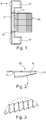
- Fig. 1 shows a plan view of a light guide device 2 with a Lichteinkoppelseite 4, a reflection side 6, a reflection layer 8 (see Fig. 2 ), and a Lichtauskoppelseite 10.
- the reflection side 6 is below the light outcoupling side 10 and the reflection layer 8 is located below the reflection side 6.
- the light outcoupling side 10 is the reflection side 6 and thus also the reflection layer 8 opposite, so that reflected light reaches the light outcoupling side 10 as evenly as possible.
- the distance between the Lichtauskoppelseite 10 and the reflection side 6 and thus also the reflection layer 8 decreases with increasing distance from the Lichteinkoppelseite 4.
- Die Lichtauskoppelseite 10 and the reflection side 6 can converge so continuously or it is an edge 14 is formed, which may also have a reflective layer 8.
- FIG. 1 shows Fig. 1 by way of example, two holding devices 12, which extend away from the light-guiding device 2 in the plane of the light outcoupling side 10, each having a predetermined breaking point 14.
- the unnecessary holding device 12 can be separated, for example, be canceled.
- Fig. 2 shows a side view of the light guide Fig. 1 .
- Light can enter the light guide device 2 via the light input side 4, in particular substantially parallel to the light outcoupling side 10. The light is then deflected via the reflection side 6 and the reflection layer 8 in the direction of the light output side 10.
- Fig. 3 shows an enlarged view of a step-like reflection side 6 and / or reflection layer 8.
- a step-like training which may be alternatively or additionally wave-like, the steering of light coming from the Lichteinkoppelseite 4 light rays to the effect that the light extraction from the Lichtauskoppelseite 10 as homogeneous as possible and is evenly distributed over the Lichtauskoppelseite 10.
- Fig. 4 shows the light guide 2 in a perspective view.
- the optimized for three light sources 18 light guide 2 has formed with three part funnels reflection side 6 and reflection layer 8. The longitudinal axis of these part funnel extends along the main direction of the injected light.
- the light guiding device 2 can be adapted for any other number of light sources 18, for example 1, 2, 3, 4, 5, 6 or more.
- Fig. 5 shows a lighting device 16 with three light sources 18, which are arranged on a circuit board 20.
- the circuit board 20 with the LED light sources 18 is arranged to the light guide device 2, that the light, as shown by the arrows, is emitted substantially parallel to the Lichtauskoppelseite 10.
- the light is deflected by the reflection side 6 and in particular by the reflection layer 8 that, as shown in the arrows in Fig. 6 can be seen, leaves the light-guiding device 2 via the light extraction side 10.
- Fig. 7 shows an exploded view of a rearview device 22 with a light guide 2, which can be arranged on a circuit board 20 or directly to a holder 32.
- the rearview device 22 further has a rearview reflecting surface 24 and an underlying heating layer 26, the rearview reflecting surface 24 having an icon for a blind spot assist display that can be illuminated via the light guiding device 2 and through a recess 30 in the heating layer 26.
- Board 20, light guide 2 and rear-reflection surface 24 with heating layer 26 can be arranged on a holder 32.
- the remaining parts of a rearview device 22, such as housings, are not shown.
Priority Applications (1)
| Application Number | Priority Date | Filing Date | Title |
|---|---|---|---|
| EP18173316.3A EP3392685B1 (fr) | 2015-01-19 | 2015-01-19 | Retroviseur pour un vehicule a moteur |
Applications Claiming Priority (2)
| Application Number | Priority Date | Filing Date | Title |
|---|---|---|---|
| EP18173316.3A EP3392685B1 (fr) | 2015-01-19 | 2015-01-19 | Retroviseur pour un vehicule a moteur |
| EP15151604.4A EP3045944B1 (fr) | 2015-01-19 | 2015-01-19 | Dispositif de conducteur lumineux |
Related Parent Applications (2)
| Application Number | Title | Priority Date | Filing Date |
|---|---|---|---|
| EP15151604.4A Division-Into EP3045944B1 (fr) | 2015-01-19 | 2015-01-19 | Dispositif de conducteur lumineux |
| EP15151604.4A Division EP3045944B1 (fr) | 2015-01-19 | 2015-01-19 | Dispositif de conducteur lumineux |
Publications (2)
| Publication Number | Publication Date |
|---|---|
| EP3392685A1 true EP3392685A1 (fr) | 2018-10-24 |
| EP3392685B1 EP3392685B1 (fr) | 2021-03-03 |
Family
ID=52423581
Family Applications (2)
| Application Number | Title | Priority Date | Filing Date |
|---|---|---|---|
| EP18173316.3A Active EP3392685B1 (fr) | 2015-01-19 | 2015-01-19 | Retroviseur pour un vehicule a moteur |
| EP15151604.4A Active EP3045944B1 (fr) | 2015-01-19 | 2015-01-19 | Dispositif de conducteur lumineux |
Family Applications After (1)
| Application Number | Title | Priority Date | Filing Date |
|---|---|---|---|
| EP15151604.4A Active EP3045944B1 (fr) | 2015-01-19 | 2015-01-19 | Dispositif de conducteur lumineux |
Country Status (3)
| Country | Link |
|---|---|
| US (3) | US10168021B2 (fr) |
| EP (2) | EP3392685B1 (fr) |
| CN (2) | CN105805698A (fr) |
Families Citing this family (39)
| Publication number | Priority date | Publication date | Assignee | Title |
|---|---|---|---|---|
| US10800329B2 (en) | 2010-04-19 | 2020-10-13 | SMR Patents S.à.r.l. | Rear view mirror simulation |
| US10703299B2 (en) | 2010-04-19 | 2020-07-07 | SMR Patents S.à.r.l. | Rear view mirror simulation |
| DE102018116008B4 (de) | 2018-07-02 | 2020-07-02 | Motherson Innovations Company Limited | Basisanordnung mit Rückblickvorrichtung |
| DE102018116011B4 (de) | 2018-07-02 | 2020-07-02 | Motherson Innovations Company Limited | Dichtungsmittel, Basisanordnung mit einem solchen Dichtungsmittel und Rückblickvorrichtung mit einer solchen Basisanordnung |
| EP3632748B1 (fr) | 2018-10-04 | 2022-05-18 | Motherson Innovations Company Limited | Ensemble de vue arrière et véhicule comportant un tel ensemble de vue arrière |
| US10060594B2 (en) | 2015-01-19 | 2018-08-28 | SMR Patents S.à.r.l. | Light guiding device |
| TWI607181B (zh) * | 2015-07-06 | 2017-12-01 | 隆達電子股份有限公司 | 導光柱與使用其的車用燈具 |
| DE102015220341A1 (de) * | 2015-10-19 | 2017-04-20 | Hella Kgaa Hueck & Co. | Radom |
| EP3279036B1 (fr) | 2016-08-04 | 2021-10-27 | SMR Patents S.à.r.l. | Dispositif d'éclairage, procédé de production de celui-ci et dispositif de rétroviseur |
| EP3581984A4 (fr) * | 2017-03-14 | 2021-01-13 | Pioneer Corporation | Dispositif d'affichage |
| KR101804311B1 (ko) * | 2017-03-23 | 2017-12-04 | (주)미경테크 | 백라이트 유닛 |
| CN111094065B (zh) | 2017-03-31 | 2023-03-17 | 玛泽森创新有限公司 | 带有可互换进近灯的机动车辆的后视组件 |
| DE102017130246A1 (de) | 2017-12-15 | 2019-06-19 | Motherson Innovations Company Limited | Leuchteinrichtung, Rückblickvorrichtung und Kraftfahrzeug |
| EP4234333A3 (fr) | 2017-04-20 | 2023-11-08 | Motherson Innovations Company Ltd. | Lampe d'approche et lampe à logo combinées |
| DE102017117024B4 (de) | 2017-07-27 | 2021-01-21 | SMR Patents S.à.r.l. | Kameraanordnung und Kraftfahrzeug mit Kameraanordnung |
| US11034288B2 (en) | 2017-05-08 | 2021-06-15 | SMR Patents S,á. r.l. | Moveable illumination and image acquisition unit for a motor vehicle |
| DE102017109872B4 (de) | 2017-05-08 | 2023-05-11 | SMR Patents S.à.r.l. | Beleuchtungs- und Bildaufnahme-Einheit für ein Kraftfahrzeug |
| EP3406488B1 (fr) | 2017-05-24 | 2020-07-01 | SMR Patents S.à.r.l. | Rétroviseur externe à tête mobile |
| EP3409537B1 (fr) | 2017-05-30 | 2019-07-10 | SMR Patents S.à.r.l. | Section de tête pour un dispositif de vision arrière |
| CN109789833B (zh) | 2017-06-30 | 2022-07-26 | Smr专利责任有限公司 | 组件,组装此组件的方法,拆卸此组件的方法,具有此组件的外部后视装置以及具有此后视装置的机动车辆 |
| JP7002573B2 (ja) | 2017-06-30 | 2022-01-20 | エスエムアール・パテンツ・ソシエテ・ア・レスポンサビリテ・リミテ | 可動ヘッド組立体を備えた後方観察デバイスおよびそれを備えた車両 |
| US11370359B2 (en) | 2017-06-30 | 2022-06-28 | SMR Patents S.à.r.l. | Rearview device with moveable head assembly and vehicle therewith |
| DE102017117027B3 (de) | 2017-07-27 | 2018-12-13 | SMR Patents S.à.r.l. | Projektionsvorrichtung, Rückblickvorrichtung und Kraftfahrzeug |
| DE102017117032B4 (de) * | 2017-07-27 | 2021-01-28 | SMR Patents S.à.r.l. | Kameraanordnung und Kraftfahrzeug mit Kameraanordnung |
| DE102017117153B4 (de) | 2017-07-28 | 2021-06-02 | SMR Patents S.à.r.l. | Kameravorrichtung, Rückblickvorrichtung und Kraftfahrzeug |
| KR101820500B1 (ko) * | 2017-08-03 | 2018-01-19 | (주)미경테크 | 백라이트 유닛 |
| DE202017104834U1 (de) | 2017-08-10 | 2017-09-11 | SMR Patents S.à.r.l. | Montageanordnung für ein Außenanbauteil, Rückblickvorrichtung und Kraftfahrzeug |
| EP3451279A1 (fr) | 2017-08-30 | 2019-03-06 | SMR Patents S.à.r.l. | Simulation de rétroviseur arrière |
| DE102017121376B4 (de) | 2017-09-14 | 2021-01-14 | Motherson Innovations Company Limited | Verfahren zum Betreiben eines Kraftfahrzeugs mit zumindest einer Außenkamera sowie Kraftfahrzeug mit zumindest einer Außenkamera |
| US11799186B2 (en) * | 2017-09-20 | 2023-10-24 | Motherson Innovations Company Limited | Antenna housing, a combined antenna and indicator module and a vehicle |
| EP3480062B1 (fr) | 2017-11-01 | 2020-09-09 | SMR Patents S.à.r.l. | Dispositif de rétroviseur comportant un ensemble à tête mobile |
| CN111448102B (zh) | 2017-11-01 | 2023-11-24 | Smr专利有限公司 | 外部后视设备和车辆 |
| WO2019115746A1 (fr) | 2017-12-15 | 2019-06-20 | Motherson Innovations Company Ltd. | Dispositif d'éclairage, dispositif de rétroviseur et véhicule à moteur |
| DE102017130347A1 (de) | 2017-12-18 | 2019-06-19 | Motherson Innovations Company Limited | Leuchte sowie Rückblickvorrichtung und Kraftfahrzeug mit Leuchte |
| DE102018101036A1 (de) | 2018-01-18 | 2019-07-18 | HELLA GmbH & Co. KGaA | Heckleuchte für ein Kraftfahrzeug |
| EP3726473A1 (fr) | 2019-04-18 | 2020-10-21 | SMR Patents S.à.r.l. | Procédé de simulation de dispositif de rétroviseur |
| JP7346281B2 (ja) * | 2019-12-23 | 2023-09-19 | 美里工業株式会社 | ドアミラー用発光ユニット |
| US11589443B1 (en) * | 2021-10-08 | 2023-02-21 | Ford Global Technologies, Llc | Automatic drive mode lighting systems and methods |
| EP4180273A1 (fr) | 2021-11-11 | 2023-05-17 | SMR Patents S.à.r.l. | Ensemble, procédé de montage et de démontage d'un tel ensemble, dispositif de rétroviseur extérieur et véhicule doté d'un tel ensemble |
Citations (7)
| Publication number | Priority date | Publication date | Assignee | Title |
|---|---|---|---|---|
| WO2001027529A1 (fr) * | 1999-10-08 | 2001-04-19 | 3M Innovative Properties Company | Guide lumineux sur lequel est directement fixe un reflecteur et son procede de fabrication |
| EP1167870A2 (fr) * | 2000-07-01 | 2002-01-02 | Hella KG Hueck & Co. | Feu pour véhicule |
| EP1970736A1 (fr) * | 2007-03-14 | 2008-09-17 | Visiocorp Patents S.à.r.l. | Rétroviseur extérieur pour véhicules, de préférence pour véhicules automobiles |
| DE202012100398U1 (de) * | 2011-02-17 | 2012-02-16 | Insta Elektro Gmbh | Beleuchtungseinrichtung |
| EP2463157A1 (fr) * | 2010-12-10 | 2012-06-13 | SMR Patents S.à.r.l. | Ensemble de rétroviseur avec indicateur optique |
| US20130300982A1 (en) * | 2011-01-28 | 2013-11-14 | Sharp Kabushiki Kaisha | Planar lighting device, electronic device provided therewith, and liquid-crystal display device |
| US20140140084A1 (en) * | 2012-11-22 | 2014-05-22 | Automotive Lighting Reutlingen Gmbh | Motor vehicle light with a light conductor and a shield that is visible through the light conductor |
Family Cites Families (20)
| Publication number | Priority date | Publication date | Assignee | Title |
|---|---|---|---|---|
| US4912606A (en) * | 1987-10-28 | 1990-03-27 | Koito Manufacturing Co., Ltd. | Vehicle lamp device |
| US5700078A (en) * | 1996-12-23 | 1997-12-23 | Ford Global Technologies, Inc. | Laser illuminated lighting system |
| US6623132B2 (en) * | 1999-08-11 | 2003-09-23 | North American Lighting, Inc. | Light coupler hingedly attached to a light guide for automotive lighting |
| US6428176B1 (en) * | 1999-10-27 | 2002-08-06 | Gateway, Inc. | Backlit liquid crystal display structure for a laptop computer |
| ES2168071B1 (es) * | 2000-07-12 | 2003-07-16 | Barros Alejandro Rodriguez | Retrovisor modular con señales multiples intercambiables para vehiculos de 2, 3, 4 o mas ruedas. |
| DE10134641A1 (de) * | 2001-07-17 | 2003-05-22 | Arvinmeritor Gmbh | Schiebedach für ein Fahrzeug |
| JP4068387B2 (ja) * | 2002-04-23 | 2008-03-26 | 株式会社小糸製作所 | 光源ユニット |
| US6824284B2 (en) * | 2002-06-25 | 2004-11-30 | Visteon Global Technologies, Inc. | Edge-lit optical element having a manifold and lamp assembly utilizing such element |
| JP2004103379A (ja) * | 2002-09-09 | 2004-04-02 | Koito Mfg Co Ltd | 車両用標識灯 |
| JP2004179116A (ja) * | 2002-11-29 | 2004-06-24 | Alps Electric Co Ltd | 背面照明装置及び液晶表示装置 |
| JP4286674B2 (ja) * | 2004-01-14 | 2009-07-01 | 本田技研工業株式会社 | 車両用灯体制御装置 |
| US8033706B1 (en) * | 2004-09-09 | 2011-10-11 | Fusion Optix, Inc. | Lightguide comprising a low refractive index region |
| KR100601708B1 (ko) * | 2004-11-17 | 2006-07-18 | 삼성전자주식회사 | 반사형 콜리메이터를 구비한 조명장치 및 이를 채용한화상투사장치 |
| KR100619070B1 (ko) * | 2005-03-08 | 2006-08-31 | 삼성전자주식회사 | 조명유닛 및 이를 채용한 화상투사장치 |
| US7513665B2 (en) * | 2006-05-16 | 2009-04-07 | Visteon Global Technologies, Inc. | Headlamp module and headlamp assembly with internally reflecting translucent member |
| JP5945857B2 (ja) * | 2012-01-24 | 2016-07-05 | スタンレー電気株式会社 | 車両用前照灯及び導光レンズ |
| US8858025B2 (en) * | 2012-03-07 | 2014-10-14 | Lg Innotek Co., Ltd. | Lighting device |
| US9725030B2 (en) * | 2013-08-26 | 2017-08-08 | Panasonic Intellectual Property Management Co., Ltd. | Vehicle light and vehicle equipped with vehicle light |
| JP6127269B2 (ja) * | 2013-08-26 | 2017-05-17 | パナソニックIpマネジメント株式会社 | 車載用ライトとそれを搭載した自動車 |
| FR3012203B1 (fr) * | 2013-10-23 | 2015-10-30 | Valeo Vision | Dispositif d'eclairage comportant un guide de rayons lumineux |
-
2015
- 2015-01-19 EP EP18173316.3A patent/EP3392685B1/fr active Active
- 2015-01-19 EP EP15151604.4A patent/EP3045944B1/fr active Active
-
2016
- 2016-01-18 CN CN201610030718.4A patent/CN105805698A/zh active Pending
- 2016-01-18 CN CN201810531590.9A patent/CN108916824A/zh active Pending
- 2016-01-19 US US15/000,733 patent/US10168021B2/en active Active
-
2018
- 2018-03-09 US US15/916,650 patent/US10415792B2/en active Active
- 2018-08-07 US US16/057,157 patent/US10393345B2/en active Active
Patent Citations (7)
| Publication number | Priority date | Publication date | Assignee | Title |
|---|---|---|---|---|
| WO2001027529A1 (fr) * | 1999-10-08 | 2001-04-19 | 3M Innovative Properties Company | Guide lumineux sur lequel est directement fixe un reflecteur et son procede de fabrication |
| EP1167870A2 (fr) * | 2000-07-01 | 2002-01-02 | Hella KG Hueck & Co. | Feu pour véhicule |
| EP1970736A1 (fr) * | 2007-03-14 | 2008-09-17 | Visiocorp Patents S.à.r.l. | Rétroviseur extérieur pour véhicules, de préférence pour véhicules automobiles |
| EP2463157A1 (fr) * | 2010-12-10 | 2012-06-13 | SMR Patents S.à.r.l. | Ensemble de rétroviseur avec indicateur optique |
| US20130300982A1 (en) * | 2011-01-28 | 2013-11-14 | Sharp Kabushiki Kaisha | Planar lighting device, electronic device provided therewith, and liquid-crystal display device |
| DE202012100398U1 (de) * | 2011-02-17 | 2012-02-16 | Insta Elektro Gmbh | Beleuchtungseinrichtung |
| US20140140084A1 (en) * | 2012-11-22 | 2014-05-22 | Automotive Lighting Reutlingen Gmbh | Motor vehicle light with a light conductor and a shield that is visible through the light conductor |
Also Published As
| Publication number | Publication date |
|---|---|
| EP3045944B1 (fr) | 2020-06-17 |
| EP3045944A1 (fr) | 2016-07-20 |
| US10415792B2 (en) | 2019-09-17 |
| US10393345B2 (en) | 2019-08-27 |
| EP3392685B1 (fr) | 2021-03-03 |
| US10168021B2 (en) | 2019-01-01 |
| US20180340673A1 (en) | 2018-11-29 |
| US20180195687A1 (en) | 2018-07-12 |
| CN108916824A (zh) | 2018-11-30 |
| US20160209000A1 (en) | 2016-07-21 |
| CN105805698A (zh) | 2016-07-27 |
Similar Documents
| Publication | Publication Date | Title |
|---|---|---|
| EP3392685B1 (fr) | Retroviseur pour un vehicule a moteur | |
| DE102012107834A1 (de) | Beleuchtungseinrichtung und Rückblickeinrichtung | |
| DE102012107833A1 (de) | Beleuchtungseinrichtung und Rückblickeinrichtung | |
| DE102005011715B4 (de) | Innenleuchte eines Fahrzeugs | |
| DE102016007709B4 (de) | Kraftfahrzeugzierteil | |
| DE202009011238U1 (de) | Kraftfahrzeug-Innenauskleidungsteil mit Lichtleiter | |
| DE102015013669A1 (de) | Hinterleuchtetes Innenausstattungsteil für ein Kraftfahrzeug | |
| EP2803531A1 (fr) | Dispositif plat destiné à éclairer l'équipement intérieur d'un véhicule | |
| EP2942233A1 (fr) | Élément d'éclairage plat pour l'équipement intérieur d'un véhicule | |
| DE102011016396A1 (de) | Dekorformteil für den Innenraum eines Fahrzeugs sowie Innenraumverkleidung mit dem Dekorformteil | |
| DE102008056985A1 (de) | Zierleuchteneinheit für Fahrzeuge | |
| DE202022103655U1 (de) | Lichtleiter | |
| DE202017105880U1 (de) | Formteil, insbesondere als Formteil ausgebildetes Dekorteil und/oder Verkleidungsteil für einen Fahrzeuginnenraum | |
| DE202016003741U1 (de) | Kraftfahrzeug mit Lichtleiter | |
| EP3061587B1 (fr) | Procédé de fabrication d'une lampe pour véhicules et rétroviseur extérieur d'un véhicule doté d'une lampe ainsi fabriquée | |
| EP3407369B1 (fr) | Dispositif, système et procédé de représentation d'un symbole lumineux flottant | |
| DE102013007856A1 (de) | Lichtleitkörper und Leuchtvorrichtung mit dem Lichtleitkörper | |
| DE202016104031U1 (de) | Formteil, insbesondere als Formteil ausgebildetes Dekorteil und/oder Verkleidungsteil für einen Fahrzeuginnenraum | |
| WO2015154939A1 (fr) | Dispositif d'affichage d'un symbole et procédé de production d'un dispositif d'affichage d'un symbole | |
| DE102013101198A1 (de) | Beleuchtungsvorrichtung für Fahrzeuge sowie Verfahren | |
| EP3509911B1 (fr) | Pièce décorative pour habitacle de véhicule et procédé de fabrication d'une pièce moulée de ce type | |
| DE102007038470A1 (de) | Beleuchtungseinrichtung für Fahrzeuge | |
| DE102011118219A1 (de) | Leuchteinrichtung für ein Kraftfahrzeug | |
| DE102014010310B3 (de) | Beleuchtetes Zeigerinstrument für ein Kraftfahrzeug | |
| EP3853518B1 (fr) | Module d'éclairage, notamment destiné à être utilisé dans un dispositif d'éclairage pour véhicule automobile |
Legal Events
| Date | Code | Title | Description |
|---|---|---|---|
| PUAI | Public reference made under article 153(3) epc to a published international application that has entered the european phase |
Free format text: ORIGINAL CODE: 0009012 |
|
| STAA | Information on the status of an ep patent application or granted ep patent |
Free format text: STATUS: THE APPLICATION HAS BEEN PUBLISHED |
|
| AC | Divisional application: reference to earlier application |
Ref document number: 3045944 Country of ref document: EP Kind code of ref document: P |
|
| AK | Designated contracting states |
Kind code of ref document: A1 Designated state(s): AL AT BE BG CH CY CZ DE DK EE ES FI FR GB GR HR HU IE IS IT LI LT LU LV MC MK MT NL NO PL PT RO RS SE SI SK SM TR |
|
| STAA | Information on the status of an ep patent application or granted ep patent |
Free format text: STATUS: REQUEST FOR EXAMINATION WAS MADE |
|
| 17P | Request for examination filed |
Effective date: 20181109 |
|
| RBV | Designated contracting states (corrected) |
Designated state(s): AL AT BE BG CH CY CZ DE DK EE ES FI FR GB GR HR HU IE IS IT LI LT LU LV MC MK MT NL NO PL PT RO RS SE SI SK SM TR |
|
| RIN1 | Information on inventor provided before grant (corrected) |
Inventor name: FRITZ, DANIEL Inventor name: KUERSCHNER, NORBERT |
|
| STAA | Information on the status of an ep patent application or granted ep patent |
Free format text: STATUS: EXAMINATION IS IN PROGRESS |
|
| 17Q | First examination report despatched |
Effective date: 20200214 |
|
| GRAP | Despatch of communication of intention to grant a patent |
Free format text: ORIGINAL CODE: EPIDOSNIGR1 |
|
| STAA | Information on the status of an ep patent application or granted ep patent |
Free format text: STATUS: GRANT OF PATENT IS INTENDED |
|
| INTG | Intention to grant announced |
Effective date: 20200923 |
|
| GRAS | Grant fee paid |
Free format text: ORIGINAL CODE: EPIDOSNIGR3 |
|
| STAA | Information on the status of an ep patent application or granted ep patent |
Free format text: STATUS: GRANT OF PATENT IS INTENDED |
|
| GRAA | (expected) grant |
Free format text: ORIGINAL CODE: 0009210 |
|
| STAA | Information on the status of an ep patent application or granted ep patent |
Free format text: STATUS: THE PATENT HAS BEEN GRANTED |
|
| AC | Divisional application: reference to earlier application |
Ref document number: 3045944 Country of ref document: EP Kind code of ref document: P |
|
| AK | Designated contracting states |
Kind code of ref document: B1 Designated state(s): AL AT BE BG CH CY CZ DE DK EE ES FI FR GB GR HR HU IE IS IT LI LT LU LV MC MK MT NL NO PL PT RO RS SE SI SK SM TR |
|
| REG | Reference to a national code |
Ref country code: GB Ref legal event code: FG4D Free format text: NOT ENGLISH |
|
| REG | Reference to a national code |
Ref country code: AT Ref legal event code: REF Ref document number: 1367829 Country of ref document: AT Kind code of ref document: T Effective date: 20210315 Ref country code: CH Ref legal event code: EP |
|
| REG | Reference to a national code |
Ref country code: DE Ref legal event code: R096 Ref document number: 502015014357 Country of ref document: DE |
|
| REG | Reference to a national code |
Ref country code: IE Ref legal event code: FG4D Free format text: LANGUAGE OF EP DOCUMENT: GERMAN |
|
| REG | Reference to a national code |
Ref country code: LT Ref legal event code: MG9D |
|
| PG25 | Lapsed in a contracting state [announced via postgrant information from national office to epo] |
Ref country code: NO Free format text: LAPSE BECAUSE OF FAILURE TO SUBMIT A TRANSLATION OF THE DESCRIPTION OR TO PAY THE FEE WITHIN THE PRESCRIBED TIME-LIMIT Effective date: 20210603 Ref country code: LT Free format text: LAPSE BECAUSE OF FAILURE TO SUBMIT A TRANSLATION OF THE DESCRIPTION OR TO PAY THE FEE WITHIN THE PRESCRIBED TIME-LIMIT Effective date: 20210303 Ref country code: FI Free format text: LAPSE BECAUSE OF FAILURE TO SUBMIT A TRANSLATION OF THE DESCRIPTION OR TO PAY THE FEE WITHIN THE PRESCRIBED TIME-LIMIT Effective date: 20210303 Ref country code: GR Free format text: LAPSE BECAUSE OF FAILURE TO SUBMIT A TRANSLATION OF THE DESCRIPTION OR TO PAY THE FEE WITHIN THE PRESCRIBED TIME-LIMIT Effective date: 20210604 Ref country code: HR Free format text: LAPSE BECAUSE OF FAILURE TO SUBMIT A TRANSLATION OF THE DESCRIPTION OR TO PAY THE FEE WITHIN THE PRESCRIBED TIME-LIMIT Effective date: 20210303 Ref country code: BG Free format text: LAPSE BECAUSE OF FAILURE TO SUBMIT A TRANSLATION OF THE DESCRIPTION OR TO PAY THE FEE WITHIN THE PRESCRIBED TIME-LIMIT Effective date: 20210603 |
|
| REG | Reference to a national code |
Ref country code: NL Ref legal event code: MP Effective date: 20210303 |
|
| PG25 | Lapsed in a contracting state [announced via postgrant information from national office to epo] |
Ref country code: SE Free format text: LAPSE BECAUSE OF FAILURE TO SUBMIT A TRANSLATION OF THE DESCRIPTION OR TO PAY THE FEE WITHIN THE PRESCRIBED TIME-LIMIT Effective date: 20210303 Ref country code: RS Free format text: LAPSE BECAUSE OF FAILURE TO SUBMIT A TRANSLATION OF THE DESCRIPTION OR TO PAY THE FEE WITHIN THE PRESCRIBED TIME-LIMIT Effective date: 20210303 Ref country code: PL Free format text: LAPSE BECAUSE OF FAILURE TO SUBMIT A TRANSLATION OF THE DESCRIPTION OR TO PAY THE FEE WITHIN THE PRESCRIBED TIME-LIMIT Effective date: 20210303 Ref country code: LV Free format text: LAPSE BECAUSE OF FAILURE TO SUBMIT A TRANSLATION OF THE DESCRIPTION OR TO PAY THE FEE WITHIN THE PRESCRIBED TIME-LIMIT Effective date: 20210303 |
|
| PG25 | Lapsed in a contracting state [announced via postgrant information from national office to epo] |
Ref country code: NL Free format text: LAPSE BECAUSE OF FAILURE TO SUBMIT A TRANSLATION OF THE DESCRIPTION OR TO PAY THE FEE WITHIN THE PRESCRIBED TIME-LIMIT Effective date: 20210303 |
|
| PG25 | Lapsed in a contracting state [announced via postgrant information from national office to epo] |
Ref country code: CZ Free format text: LAPSE BECAUSE OF FAILURE TO SUBMIT A TRANSLATION OF THE DESCRIPTION OR TO PAY THE FEE WITHIN THE PRESCRIBED TIME-LIMIT Effective date: 20210303 Ref country code: EE Free format text: LAPSE BECAUSE OF FAILURE TO SUBMIT A TRANSLATION OF THE DESCRIPTION OR TO PAY THE FEE WITHIN THE PRESCRIBED TIME-LIMIT Effective date: 20210303 Ref country code: SM Free format text: LAPSE BECAUSE OF FAILURE TO SUBMIT A TRANSLATION OF THE DESCRIPTION OR TO PAY THE FEE WITHIN THE PRESCRIBED TIME-LIMIT Effective date: 20210303 |
|
| REG | Reference to a national code |
Ref country code: DE Ref legal event code: R084 Ref document number: 502015014357 Country of ref document: DE |
|
| PG25 | Lapsed in a contracting state [announced via postgrant information from national office to epo] |
Ref country code: IS Free format text: LAPSE BECAUSE OF FAILURE TO SUBMIT A TRANSLATION OF THE DESCRIPTION OR TO PAY THE FEE WITHIN THE PRESCRIBED TIME-LIMIT Effective date: 20210703 Ref country code: PT Free format text: LAPSE BECAUSE OF FAILURE TO SUBMIT A TRANSLATION OF THE DESCRIPTION OR TO PAY THE FEE WITHIN THE PRESCRIBED TIME-LIMIT Effective date: 20210705 Ref country code: RO Free format text: LAPSE BECAUSE OF FAILURE TO SUBMIT A TRANSLATION OF THE DESCRIPTION OR TO PAY THE FEE WITHIN THE PRESCRIBED TIME-LIMIT Effective date: 20210303 Ref country code: SK Free format text: LAPSE BECAUSE OF FAILURE TO SUBMIT A TRANSLATION OF THE DESCRIPTION OR TO PAY THE FEE WITHIN THE PRESCRIBED TIME-LIMIT Effective date: 20210303 |
|
| REG | Reference to a national code |
Ref country code: DE Ref legal event code: R097 Ref document number: 502015014357 Country of ref document: DE |
|
| PLBE | No opposition filed within time limit |
Free format text: ORIGINAL CODE: 0009261 |
|
| STAA | Information on the status of an ep patent application or granted ep patent |
Free format text: STATUS: NO OPPOSITION FILED WITHIN TIME LIMIT |
|
| PG25 | Lapsed in a contracting state [announced via postgrant information from national office to epo] |
Ref country code: AL Free format text: LAPSE BECAUSE OF FAILURE TO SUBMIT A TRANSLATION OF THE DESCRIPTION OR TO PAY THE FEE WITHIN THE PRESCRIBED TIME-LIMIT Effective date: 20210303 Ref country code: DK Free format text: LAPSE BECAUSE OF FAILURE TO SUBMIT A TRANSLATION OF THE DESCRIPTION OR TO PAY THE FEE WITHIN THE PRESCRIBED TIME-LIMIT Effective date: 20210303 Ref country code: ES Free format text: LAPSE BECAUSE OF FAILURE TO SUBMIT A TRANSLATION OF THE DESCRIPTION OR TO PAY THE FEE WITHIN THE PRESCRIBED TIME-LIMIT Effective date: 20210303 |
|
| 26N | No opposition filed |
Effective date: 20211206 |
|
| PG25 | Lapsed in a contracting state [announced via postgrant information from national office to epo] |
Ref country code: SI Free format text: LAPSE BECAUSE OF FAILURE TO SUBMIT A TRANSLATION OF THE DESCRIPTION OR TO PAY THE FEE WITHIN THE PRESCRIBED TIME-LIMIT Effective date: 20210303 |
|
| PG25 | Lapsed in a contracting state [announced via postgrant information from national office to epo] |
Ref country code: IT Free format text: LAPSE BECAUSE OF FAILURE TO SUBMIT A TRANSLATION OF THE DESCRIPTION OR TO PAY THE FEE WITHIN THE PRESCRIBED TIME-LIMIT Effective date: 20210303 |
|
| PG25 | Lapsed in a contracting state [announced via postgrant information from national office to epo] |
Ref country code: IS Free format text: LAPSE BECAUSE OF FAILURE TO SUBMIT A TRANSLATION OF THE DESCRIPTION OR TO PAY THE FEE WITHIN THE PRESCRIBED TIME-LIMIT Effective date: 20210703 |
|
| PG25 | Lapsed in a contracting state [announced via postgrant information from national office to epo] |
Ref country code: MC Free format text: LAPSE BECAUSE OF FAILURE TO SUBMIT A TRANSLATION OF THE DESCRIPTION OR TO PAY THE FEE WITHIN THE PRESCRIBED TIME-LIMIT Effective date: 20210303 |
|
| REG | Reference to a national code |
Ref country code: CH Ref legal event code: PL |
|
| REG | Reference to a national code |
Ref country code: BE Ref legal event code: MM Effective date: 20220131 |
|
| PG25 | Lapsed in a contracting state [announced via postgrant information from national office to epo] |
Ref country code: LU Free format text: LAPSE BECAUSE OF NON-PAYMENT OF DUE FEES Effective date: 20220119 |
|
| PG25 | Lapsed in a contracting state [announced via postgrant information from national office to epo] |
Ref country code: BE Free format text: LAPSE BECAUSE OF NON-PAYMENT OF DUE FEES Effective date: 20220131 |
|
| PG25 | Lapsed in a contracting state [announced via postgrant information from national office to epo] |
Ref country code: LI Free format text: LAPSE BECAUSE OF NON-PAYMENT OF DUE FEES Effective date: 20220131 Ref country code: CH Free format text: LAPSE BECAUSE OF NON-PAYMENT OF DUE FEES Effective date: 20220131 |
|
| PG25 | Lapsed in a contracting state [announced via postgrant information from national office to epo] |
Ref country code: IE Free format text: LAPSE BECAUSE OF NON-PAYMENT OF DUE FEES Effective date: 20220119 |
|
| REG | Reference to a national code |
Ref country code: AT Ref legal event code: MM01 Ref document number: 1367829 Country of ref document: AT Kind code of ref document: T Effective date: 20220119 |
|
| PG25 | Lapsed in a contracting state [announced via postgrant information from national office to epo] |
Ref country code: AT Free format text: LAPSE BECAUSE OF NON-PAYMENT OF DUE FEES Effective date: 20220119 |
|
| PGFP | Annual fee paid to national office [announced via postgrant information from national office to epo] |
Ref country code: FR Payment date: 20230123 Year of fee payment: 9 |
|
| PGFP | Annual fee paid to national office [announced via postgrant information from national office to epo] |
Ref country code: GB Payment date: 20230124 Year of fee payment: 9 Ref country code: DE Payment date: 20230119 Year of fee payment: 9 |
|
| P01 | Opt-out of the competence of the unified patent court (upc) registered |
Effective date: 20230616 |
|
| PG25 | Lapsed in a contracting state [announced via postgrant information from national office to epo] |
Ref country code: HU Free format text: LAPSE BECAUSE OF FAILURE TO SUBMIT A TRANSLATION OF THE DESCRIPTION OR TO PAY THE FEE WITHIN THE PRESCRIBED TIME-LIMIT; INVALID AB INITIO Effective date: 20150119 |