EP3391987A1 - Verfahren zum verschweissen von blechzuschnitten - Google Patents
Verfahren zum verschweissen von blechzuschnitten Download PDFInfo
- Publication number
- EP3391987A1 EP3391987A1 EP18162930.4A EP18162930A EP3391987A1 EP 3391987 A1 EP3391987 A1 EP 3391987A1 EP 18162930 A EP18162930 A EP 18162930A EP 3391987 A1 EP3391987 A1 EP 3391987A1
- Authority
- EP
- European Patent Office
- Prior art keywords
- sheet metal
- welding
- blank
- blanks
- carousel
- Prior art date
- Legal status (The legal status is an assumption and is not a legal conclusion. Google has not performed a legal analysis and makes no representation as to the accuracy of the status listed.)
- Granted
Links
Images



Classifications
-
- B—PERFORMING OPERATIONS; TRANSPORTING
- B23—MACHINE TOOLS; METAL-WORKING NOT OTHERWISE PROVIDED FOR
- B23K—SOLDERING OR UNSOLDERING; WELDING; CLADDING OR PLATING BY SOLDERING OR WELDING; CUTTING BY APPLYING HEAT LOCALLY, e.g. FLAME CUTTING; WORKING BY LASER BEAM
- B23K11/00—Resistance welding; Severing by resistance heating
- B23K11/10—Spot welding; Stitch welding
- B23K11/11—Spot welding
-
- B—PERFORMING OPERATIONS; TRANSPORTING
- B23—MACHINE TOOLS; METAL-WORKING NOT OTHERWISE PROVIDED FOR
- B23K—SOLDERING OR UNSOLDERING; WELDING; CLADDING OR PLATING BY SOLDERING OR WELDING; CUTTING BY APPLYING HEAT LOCALLY, e.g. FLAME CUTTING; WORKING BY LASER BEAM
- B23K26/00—Working by laser beam, e.g. welding, cutting or boring
- B23K26/20—Bonding
- B23K26/21—Bonding by welding
- B23K26/22—Spot welding
-
- B—PERFORMING OPERATIONS; TRANSPORTING
- B23—MACHINE TOOLS; METAL-WORKING NOT OTHERWISE PROVIDED FOR
- B23K—SOLDERING OR UNSOLDERING; WELDING; CLADDING OR PLATING BY SOLDERING OR WELDING; CUTTING BY APPLYING HEAT LOCALLY, e.g. FLAME CUTTING; WORKING BY LASER BEAM
- B23K37/00—Auxiliary devices or processes, not specially adapted for a procedure covered by only one of the other main groups of this subclass
- B23K37/04—Auxiliary devices or processes, not specially adapted for a procedure covered by only one of the other main groups of this subclass for holding or positioning work
- B23K37/0408—Auxiliary devices or processes, not specially adapted for a procedure covered by only one of the other main groups of this subclass for holding or positioning work for planar work
-
- B—PERFORMING OPERATIONS; TRANSPORTING
- B23—MACHINE TOOLS; METAL-WORKING NOT OTHERWISE PROVIDED FOR
- B23K—SOLDERING OR UNSOLDERING; WELDING; CLADDING OR PLATING BY SOLDERING OR WELDING; CUTTING BY APPLYING HEAT LOCALLY, e.g. FLAME CUTTING; WORKING BY LASER BEAM
- B23K37/00—Auxiliary devices or processes, not specially adapted for a procedure covered by only one of the other main groups of this subclass
- B23K37/04—Auxiliary devices or processes, not specially adapted for a procedure covered by only one of the other main groups of this subclass for holding or positioning work
- B23K37/047—Auxiliary devices or processes, not specially adapted for a procedure covered by only one of the other main groups of this subclass for holding or positioning work moving work to adjust its position between soldering, welding or cutting steps
-
- B—PERFORMING OPERATIONS; TRANSPORTING
- B23—MACHINE TOOLS; METAL-WORKING NOT OTHERWISE PROVIDED FOR
- B23K—SOLDERING OR UNSOLDERING; WELDING; CLADDING OR PLATING BY SOLDERING OR WELDING; CUTTING BY APPLYING HEAT LOCALLY, e.g. FLAME CUTTING; WORKING BY LASER BEAM
- B23K2101/00—Articles made by soldering, welding or cutting
- B23K2101/18—Sheet panels
- B23K2101/185—Tailored blanks
Definitions
- the invention relates to a method for welding sheet metal blanks to patchwork blanks according to the features in patent claim 1.
- a tailored blank is a sheet metal blank, which is typically composed of different material grades and sheet thicknesses. Such a prefabricated semi-finished product can then be converted, for example, by deep drawing to a desired component. Tailored blanks are available in the form of patchwork blanks. In this case, smaller sheets such as patches are welded onto a larger board by resistance spot welding or laser beam welding or glued using structural adhesives.
- patchwork blanks for example, A-pillars of automobiles can be manufactured.
- First generations of patchwork blanks machines use a handling robot, both of which together Connecting sheet metal blanks seperates from containers separately, calibrated their respective position and then superimposed.
- stable spot welding electrodes for example a welding press or welding tongs, the patches were welded.
- the finished welded pair of sinkers is transferred to a transport container with the same robot.
- a further development provides for two handling robots.
- the sheet metal blanks are picked up separately from the containers, calibrated for their position and placed on top of each other on a horizontal welding table.
- the welding table fixes this pair of sheet metal blanks via fixing means and one or two robots with welding tongs weld these boards together.
- the finished welded pair of boards is then relaxed by the clamping devices and the handling robot grips the finished welded pair of boards to move it into a transport container.
- the object of the invention is to further develop a method for welding sheet metal blanks to patchwork blanks, in order to increase the welding power relative to the same production surface.
- the sheet metal blanks to be welded are first provided and moved after the supply by means of handling robots.
- the handling robots place a first sheet blank and at least one further sheet blank in an aligned position on the first sheet blank.
- the first handling robot places the first sheet metal blank on a centering table in a centering position within the welding booth.
- the further sheet metal blank is positioned in the aligned position on the first sheet metal blank.
- the prefixing of the sheet metal components also takes place on the centering table, d. H. in a substantially horizontal position.
- the first sheet metal blank may be the smaller sheet metal blank. It can first be calibrated on the centering table in its position and then gripped and moved to the desired welding position. By spot welding the first sheet metal blank is connected by means of a welding robot with the second sheet metal blank. This serves to pre-fix the sheet metal blanks.
- the prefixed sheet metal components are transferred by means of a handling robot to a welding carousel and fixed there in a substantially vertical position on a holder. Arrived in this vertical position, the sheet metal component is fixed by clamping on the welding carousel. After fixing the position, the welding carousel passes by rotating the prefixed sheet metal components past several welding robots in order to carry out further spot welding. This can be 2 to 6, preferably four welding positions. Finally, the finished patchwork blank reaches a transfer position of the welding carousel, where it is removed from another handling robot and transferred to a transport container for further processing.
- An important operation of the invention is that the sheet metal blank is displaced from the substantially horizontal position to a vertical position after prefixing, by transferring the prefixed sheet metal components to the welding carousel.
- the centering table is after a short time again to accommodate more sheet blanks available, which in turn can be prefixed by spot welding.
- the inventive method has the considerable advantage that no horizontal displacement of the centering tables is required. Due to the simultaneous loading and unloading processes of the welding carousel and the welding processes carried out in parallel there are considerable time savings, so that a two to four times greater welding performance can be achieved with the same production area of about 100 m 2 .
- the welding capacity can be further increased, for example by the use of double welding guns on the welding robots and as a result the manufacturing costs are reduced.
- With the invention it is possible to position both the main circuit board as the first sheet metal blank on the centering table and then to arrange the second sheet metal blank as a patch above the first sheet metal blank.
- the welding table is designed to fix the smaller sheet metal blank, ie the patch, down, wherein the larger board is fixed on top resting on the handling robot.
- a welding robot can set two welding spots per patch. The prefixed pair of sheet metal blanks is removed from the centering table with the handling robot.
- the sheet metal blanks are fixed on the centering table by means of fixing, which clamp the sheet metal blanks either mechanically with flat jaws or one-sided magnetically fix.
- a clamping device for flat sheet metal blanks is arranged, which surrounds the sheet metal blanks at an edge region.
- Several clamping devices can be arranged on the holder.
- the holder is adapted to accommodate different sheet metal blanks, so that no conversion of the holder is required.
- the movement of the welding carousel takes place preferably clocked by a processing station to the next processing station.
- the welding carousel is divided into 60 ° steps and moved accordingly.
- a loading station and an unloading station and between loading and unloading station are four further welding stations, each with a welding robot.
- Each welding robot manufactures a part of the total welding points to be produced.
- the welding of sheet metal blanks is much faster, because several welding robots can work simultaneously on a single sheet metal blank. The welding robots also do not hinder each other.
- the number of welding robots is preferably chosen so that there is a balance between the handling time for loading and unloading and the welding time.
- the vertical orientation of the sheet metal blanks on the welding carousel saves a lot of space.
- the invention is therefore very suitable for components with many welds, as is the case with patchwork blanks.
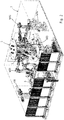
- FIG. 1 shows a welding booth 1, within which the inventive method for producing patchwork blanks from sheet metal blanks is performed.
- the sheet metal blanks are in the representation of FIG. 1 supplied from below.
- the arrows P1 and P2 illustrate that two transport containers can be transported into corresponding transport receptacles of the welding booth 1. If a transport container is empty, the production can be continued with the sheet metal blanks in the second transport container, while the empty transport container is replaced. The same applies to the second sheet metal blanks which are fed to the welding booth 1 via further transport containers according to the arrows P3 and P4.
- the finished patchwork blanks are also stored in designated transport containers. Again, no interruption of the manufacturing process is required when a transport container is full, as there is always an empty transport container in one of the designated bays.
- the sheet metal blanks 2, 3 to be welded are positioned on a centering table 4 by handling robots HR1 and HR2.
- the centering table 4 is used to bring the individual sheet metal blanks 2, 3 in a correct position and then superimposed. Lying on the centering table 4, the sheet metal blanks 2, 3 stapled by spot welding and prefixed. This is done by means of the welding robot WR1.
- the sheet metal blanks 2, 3 connected to one another are transferred to a welding carousel 5 by means of the handling robot HR2.
- the prefixed sheet metal parts 2, 3 are fixed from their horizontal position in a substantially vertical position on holders, which will be discussed later.
- the welding carousel 5 has a total of six holders. It is timed to move 60 degrees further.
- the sheet metal blanks 2, 3 are further moved by the first welding robot WR1 to three further welding robots WR2, WR3, WR4 and then arrive at a transfer position at which the finished welded patchwork blank 6 is transferred from a handling robot HR3 into the transport containers provided for this purpose can be removed from the welding booth 1 alternately in the direction of the arrows P5, P6.
- a total of four welding robots WR1 - 4 are provided.
- at least two welding robots or two welding points are provided on the welding carousel 5.
- the centering table 4 and the first welding position of the welding carousel 5 are located in the working space of the first welding robot WR1. Free time of this first welding robot WR1 becomes after the prefixing to the dotting, d. H. used for producing further spot welds on the welding carousel 5.
- FIG. 2 shows the welding booth 1 of FIG. 1 again in a perspective view, in particular, the welding carousel 5 is easier to see.
- the sheet metal blanks 2, 3 to be machined are in this very compact welding carousel 5 in a vertical position, whereby much horizontal space can be saved because even longer blanks 2 require only very little base area during welding, unlike the horizontal welding.
- FIG. 3 shows in detail the centering table 4 with a series of centering projections 7, via which the sheet metal blanks 2, 3 can be accurately positioned prior to assembly.
- the sheet metal blanks 2, 3 are successively superimposed in the region of the openings 8 in the centering table 4.
- FIG. 4 shows how a welding robot WR1 performs spot welds in the area of the central opening 8 on the sheet metal blanks 2, 3 lying one above the other there, and thus prefixes the sheet metal blanks 2, 3.
- Above the upper sheet metal blank 2 is a transport tool 9 of the handling robot HR1, not shown, which positions the larger sheet metal blank 2 above the smaller sheet metal blank 3 in the region of the openings 8.
- FIG. 3 can also be seen that 4 fixing 10 are embedded in the centering table. This may be electromagnets, over which the sheet metal blanks 3 are pulled against the centering table 4 in order to fix them during welding.
- the smaller sheet metal blank 3 held by the fixing means 10 then placed the larger sheet metal blank 2 on the smaller sheet metal blank and thereby aligned by the centering projections 8.
- the handling robot HR1 passes the so prefixed component to the welding carousel 5, as for example in FIG. 5 is shown.
- the welding carousel 5 has a vertical axis of rotation. It is infinitely rotatable by 360 degrees.
- smaller patchwork blanks are arranged on individual holders 11.
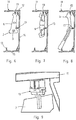
- FIGS. 6 to 8 show the holder 11.
- the holder 11 are identical in all three representations. It is a C-shaped frame structure, which is open to the radially outer side of the welding carousel 5 out.
- a clamping device 13 In the region of an upper leg 12 of the holder 11 is a clamping device 13, as in FIG. 9 is shown in magnification. Further clamping devices 13 are located on the vertical leg 14 and the lower leg 15.
- the clamping devices 13 are universal holders which are designed to clampingly receive the flat sheet metal blanks 2 between clamping jaws.
- the clamping devices 13 surround the sheet metal blanks 2 at the outer edge.
- the clamping devices 13 do not access the smaller sheet metal blanks 3, which are to be fastened on the larger sheet metal blank 2.
- the patches have already been fixed via the pre-fixing on the centering table 2. Instead of mechanical clamping devices and one-sided clamping units with proximity magnets are applicable.
- FIG. 8 shows an embodiment for a larger patchwork blank, in which all three clamping devices 13 are used to hold the patchwork blank to be produced.
- An essential advantage of the method according to the invention using such a welding carousel 5 is that the operations of loading and unloading the patchwork blanks 6 or the sheet metal blanks 2, 3 to be welded parallel to the welding operations can be done. By vertical fastening of the sheet metal blanks 2, 3 during welding considerable space is saved.
- test steps such as, for example, measuring the thickness of the components to be handled, in order to rule out accidental misuse of two sheet metal blanks lying one on top of the other.
- an identification of the manufactured patchwork blanks by means of an identification device.
- FIG. 5 shows further that the individual holders 11 need not necessarily have to point radially outwards in every position in the sense that they extend exactly radially.
- the holder 11 are themselves once again pivotally mounted about their own vertical axis on the welding carousel 5, which facilitates the loading and unloading.
- the welding carousel is in the middle of a star-shaped arrangement of handling robots HR2 for loading or unloading (handling robot HR3) and welding robots WR1-4.
- the centering table 4 is mounted pivotably to a certain extent in order to simplify the positioning of the individual sheet metal blanks 2, 3 or to optimize the handling during the welding.
- more than 3 or 4 universal clamping devices can be arranged on the holder 11 of the welding carousel. This further improves the variability.
- adjustable grippers can be attached to the handling robots.
Landscapes
- Engineering & Computer Science (AREA)
- Physics & Mathematics (AREA)
- Optics & Photonics (AREA)
- Mechanical Engineering (AREA)
- Plasma & Fusion (AREA)
- Resistance Welding (AREA)
- Manipulator (AREA)
Abstract
Description
- Die Erfindung betrifft ein Verfahren zum Verschweißen von Blechzuschnitten zu Patchwork Blanks gemäß den Merkmalen in Patentanspruch 1.
- Eine Tailored Blank ist eine Blechplatine, welche typischerweise aus verschiedenen Werkstoffgüten und Blechdicken zusammengesetzt ist. Ein derart vorgefertigtes Halbzeug kann anschließend beispielsweise durch Tiefziehen zu einem gewünschten Bauteil umgeformt werden. Tailored Blanks gibt es in der Form von Patchwork Blanks. Hierbei werden kleinere Bleche wie Flicken auf eine größere Platine mittels Widerstandspunktschweißen oder Laserstrahlschweißen aufgeschweißt oder mittels Strukturklebstoffen aufgeklebt.
- Aus derartigen Patchworkblanks können zum Beispiel A-Säulen von Kraftfahrzeugen hergestellten werden. Erste Generationen von Anlagen zur Herstellung von Patchwork Blanks verwendet einen Handhabungsroboter, der beide miteinander zu verbindenden Blechzuschnitte separat aus Behältern greift, ihre jeweilige Position kalibriert und dann übereinander legt. Mit stabil stehenden Punktschweißelektroden, zum Beispiel einer Schweißpresse oder Schweißzange, wurden die Patches verschweißt. Das fertig geschweißte Platinenpaar wird mit demselben Roboter in einen Transportbehälter verlagert.
- Eine Weiterentwicklung sieht zwei Handhabungsroboter vor. Die Blechzuschnitte werden separat aus den Behältern aufgenommen, hinsichtlich ihrer Position kalibriert und auf einem horizontalen Schweißtisch übereinander gelegt. Der Schweißtisch fixiert über Fixiermittel dieses Paar von Blechzuschnitten und ein oder zwei Roboter mit Schweißzangen schweißen diese Platinen zusammen. Das fertig geschweißte Platinenpaar wird anschließend von den Klemmvorrichtungen entspannt und der Handhabungsroboter greift das fertig geschweißte Platinenpaar, um es in einen Transportbehälter zu verlagern. Um die Handhabung und Schweißoperationen parallel ablaufen lassen zu können, ist bereits vorgeschlagen worden, zwei Schweißtische vorzusehen, die horizontal übereinander verschiebbar sind und die wechselhaft zwischen den Handhabungsrobotern zum Positionieren der Platinen und den Schweißrobotern pendeln.
- Es hat sich jedoch gezeigt, dass die Schweißleistung bezogen auf die Produktionsfläche für eine solche Anlage steigerungsfähig ist. Hoher Platzbedarf besteht durch die horizontal verschiebbaren Tische. Zudem können maximal zwei Schweißroboter gleichzeitig an einer Platine arbeiten und das auch nur in Ausnahmefällen, wenn die Schweißpunkte weit genug voneinander entfernt sind. Zudem bedeutet eine Produktänderung, dass beide Tische umgerüstet werden müssen sowie auch die Roboterprogramme geändert werden müssen und selbstverständlich auch die Behälter, mittels welcher die Blechzuschnitte bereitgestellt werden, ausgetauscht werden müssen.
- Hiervon ausgehend liegt der Erfindung die Aufgabe zugrunde, ein Verfahren zum Verschweißen von Blechzuschnitten zu Patchwork Blanks weiter zu entwickeln, um die Schweißleistung bezogen auf die gleiche Produktionsfläche zu steigern.
- Diese Aufgabe wird durch das Verfahren gemäß den Merkmalen des Patentanspruchs 1 gelöst.
- Die Unteransprüche betreffen vorteilhafte Weiterbildungen der Erfindung.
- Bei dem erfindungsgemäßen Verfahren zum Verschweißen von Blechzuschnitten zu Patchwork Blanks ist vorgesehen, dass die zu verschweißenden Blechzuschnitte zunächst bereitgestellt und nach der Bereitstellung mittels Handhabungsrobotern bewegt werden. Die Handhabungsroboter platzieren einen ersten Blechzuschnitt und wenigstens einen weiteren Blechzuschnitt in einer ausgerichteten Position auf dem ersten Blechzuschnitt. Der erste Handhabungsroboter platziert den ersten Blechzuschnitt auf einem Zentriertisch in einer Zentrierposition innerhalb der Schweißkabine. Der weitere Blechzuschnitt wird in ausgerichteter Position auf dem ersten Blechzuschnitt positioniert. Die Vorfixierung der Blechbauteile erfolgt ebenfalls auf dem Zentriertisch, d. h. in einer im Wesentlichen horizontalen Position. Dabei kann der erste Blechzuschnitt der kleinere Blechzuschnitt sein. Er kann zuerst auf dem Zentriertisch in seiner Lage kalibriert werden und danach gegriffen und in die gewünschte Schweißposition verlagert werden. Durch Punktschweißen wird der erste Blechzuschnitt mittels eines Schweißroboters mit dem zweiten Blechzuschnitt verbunden. Das dient der Vorfixierung der Blechzuschnitte.
- Die vorfixierten Blechbauteile werden mittels eines Handhabungsroboters an ein Schweißkarussell übergeben und dort in im Wesentlichen vertikaler Position an einem Halter fixiert. In dieser vertikalen Position angekommen wird das Blechbauteil an dem Schweißkarussell klemmend fixiert. Nach der Lagefixierung führt das Schweißkarussell durch eine Drehbewegung die vorfixierten Blechbauteile an mehreren Schweißrobotern vorbei, um weitere Punktschweißungen auszuführen. Das können 2 bis 6, vorzugsweise vier Schweißpositionen sein. Abschließend erreicht das fertige Patchwork Blank eine Übergabeposition des Schweißkarussells, wo es von einem weiteren Handhabungsroboter entnommen wird und in einen Transportbehälter zur Weiterverarbeitung übergeben wird.
- Ein wichtiger Arbeitsschritt der Erfindung ist, dass der Blechzuschnitt nach dem Vorfixieren von der im Wesentlichen horizontalen Position in eine vertikale Position verlagert wird, indem die vorfixierten Blechbauteile an das Schweißkarussell übergeben werden. Dadurch steht der Zentriertisch nach kürzester Zeit wieder zur Aufnahme weiterer Blechzuschnitte zur Verfügung, die wiederum mittels Punktschweißen vorfixiert werden können.
- Das erfindungsgemäße Verfahren hat den erheblichen Vorteil, dass keine horizontale Verlagerung der Zentriertische erforderlich ist. Es ergeben sich aufgrund der gleichzeitigen Be- und Entladevorgänge des Schweißkarussells und der parallel dazu ausgeführten Schweißprozesse erhebliche Zeiteinsparungen, so dass bei gleicher Produktionsfläche von ca. 100 m2 eine zwei- bis vierfach größere Schweißleistung erreicht werden kann. Die Schweißkapazität kann zum Beispiel durch den Einsatz von Doppelschweißzangen an den Schweißrobotern nochmals gesteigert werden und im Ergebnis die Fertigungskosten reduziert werden. Mit der Erfindung ist es möglich, sowohl die Hauptplatine als ersten Blechzuschnitt auf dem Zentriertisch zu positionieren und anschließend den zweiten Blechzuschnitt als Patch oberhalb des ersten Blechzuschnittes anzuordnen. Auch die umgekehrte Anordnung ist möglich, d. h. der Schweißtisch ist dazu ausgebildet, den kleineren Blechzuschnitt, d. h. das Patch, unten zu fixieren, wobei die größere Platine oben aufliegend mit dem Handhabungsroboter fixiert wird. Nun kann ein Schweißroboter zwei Schweißpunkte pro Patch setzen. Das so vorfixierte Paar von Blechzuschnitten wird mit dem Handhabungsroboter von dem Zentriertisch entnommen.
- Die Blechzuschnitte werden auf dem Zentriertisch mittels Fixiermitteln fixiert, die die Blechzuschnitte entweder mechanisch mit flachen Backen klemmen oder einseitig magnetisch fixieren. An dem Halter des Schweißkarussels ist eine Klemmvorrichtung für flache Blechzuschnitte angeordnet, welche die Blechzuschnitte an einem Randbereich umgreift. Es können mehrere Klemmvorrichtungen an dem Halter angeordnet sein. Insbesondere ist der Halter dazu ausgebildet, unterschiedliche Blechzuschnitte aufzunehmen, so dass keine Umrüstung des Halters erforderlich ist.
- Zum Einlegen des Blechzuschnittes ist es zweckmäßig, dass der Halter sich in diesem Moment nicht bewegt. Daher erfolgt die Bewegung des Schweißkarussells von einer Bearbeitungsstation zur nächsten Bearbeitungsstation vorzugsweise getaktet. Vorzugsweise wird das Schweißkarussell in 60° Schritte unterteilt und dementsprechend weiter bewegt. Bevorzugt gibt eine Beladestation und eine Entladestation und zwischen Be- und Entladestation vier weitere Schweißstationen mit jeweils einem Schweißroboter. Jeder Schweißroboter fertigt einen Teil der insgesamt anzufertigenden Schweißpunkte. Insgesamt erfolgt das Verschweißen von Blechzuschnitten wesentlich schneller, weil mehrere Schweißroboter gleichzeitig an einem einzelnen Blechzuschnitt arbeiten können. Die Schweißroboter behindern sich auch nicht gegenseitig. Die Anzahl der Schweißroboter ist vorzugsweise so gewählt, dass ein Gleichgewicht zwischen der Handhabungszeit zum Be- und Entladen und der Schweißzeit besteht. Zudem wird durch die vertikale Orientierung der Blechzuschnitte an dem Schweißkarussell viel Platz gespart. Die Erfindung eignet sich daher sehr gut für Bauteile mit vielen Schweißpunkten, wie es bei Patchworkblanks der Fall ist. An einer typischen A-Säule, die aus Patchworkblanks hergestellt wird, sind in der Regel 40 bis 110 Schweißpunkte vorgesehen.
- Das erfindungsgemäße Verfahren wird nachfolgend anhand der in den Zeichnungen dargestellten Ausführungsbeispiele näher erläutert. Es zeigt:
- Figur 1
- eine Schweißkabine zur Durchführung des Verfahrens in einer Draufsicht;
- Figur 2
- die Schweißkabine der
Figur 1 in einer perspektivischen Ansicht; - Figur 3
- einen Zentriertisch in einer ersten Ansicht;
- Figur 4
- den Schweißtisch der
Figur 3 in einer zweiten Ansicht; - Figur 5
- ein Schweißkarussell in einer perspektivischen Ansicht;
- Figur 6
- einen Halter des Schweißkarussells mit einem ersten Patchwork Blank;
- Figur 7
- den Halter der
Figur 6 mit einem zweiten Patchwork Blank; - Figur 8
- den Halter der
Figur 6 mit einem dritten Patchwork Blank und - Figur 9
- eine Klemmvorrichtung am Halter der
Figur 6 . -
Figur 1 zeigt eine Schweißkabine 1, innerhalb derer das erfindungsgemäße Verfahren zur Herstellung von Patchwork Blanks aus Blechzuschnitten durchgeführt wird. Die Blechzuschnitte werden in der Darstellung derFigur 1 von unten zugeführt. Die Pfeile P1 und P2 verdeutlichen, dass zwei Transportbehälter in entsprechende Transportaufnahmen der Schweißkabine 1 transportiert werden können. Ist ein Transportbehälter leer, kann die Produktion mit den Blechzuschnitten im zweiten Transportbehälter fortgesetzt werden, während der leere Transportbehälter ausgetauscht wird. Das Gleiche gilt für die zweiten Blechzuschnitte, die gemäß der Pfeile P3 und P4 über weitere Transportbehälter der Schweißkabine 1 zugeführt werden. - Die fertigen Patchwork Blanks werden ebenfalls in dafür vorgesehene Transportbehälter abgelegt. Auch hier ist keine Unterbrechung des Fertigungsprozesses erforderlich, wenn ein Transportbehälter voll ist, da sich immer ein leerer Transportbehälter in einer der dafür vorgesehenen Buchten befindet.
- Die zu verschweißenden Blechzuschnitte 2, 3 werden von Handhabungsrobotern HR1 und HR2 auf einem Zentriertisch 4 positioniert. Der Zentriertisch 4 dient dazu, die einzelnen Blechzuschnitte 2, 3 in eine korrekte Position zu bringen und anschließend übereinander zu legen. Auf dem Zentriertisch 4 liegend werden die Blechzuschnitte 2, 3 durch Punktschweißen geheftet und vorfixiert. Dies erfolgt mittels des Schweißroboters WR1.
- Nach dem Vorfixieren werden die so miteinander verbundenen Blechzuschnitte 2, 3 mittels des Handhabungsroboters HR2 an ein Schweißkarussell 5 übergeben. Hierbei werden die vorfixierten Blechbauteile 2, 3 von ihrer horizontalen Position in eine im Wesentlichen vertikale Position an Haltern fixiert, auf die später noch eingegangen wird. Das Schweißkarussell 5 besitzt insgesamt sechs Halter. Es wird getaktet um jeweils 60 Grad weiter bewegt. Die Blechzuschnitte 2, 3 werden von dem ersten Schweißroboter WR1 zu drei weiteren Schweißrobotern WR2, WR3, WR4 weiter bewegt und gelangen anschließend zu einer Übergabeposition, an welcher das fertig verschweißte Patchwork Blank 6 von einem Handhabungsroboter HR3 in die dafür vorgesehene Transportbehälter übergeben wird, die abwechselnd in Richtung der Pfeile P5, P6 aus der Schweißkabine 1 entfernt werden können.
- Bei diesem Ausführungsbeispiel sind insgesamt vier Schweißroboter WR1 - 4 vorgesehen. Erfindungsgemäß sind wenigstens zwei Schweißroboter bzw. zwei Schweißstellen an dem Schweißkarussell 5 vorgesehen. Beim Vorfixieren werden nur zwei Schweißpunkte je Patch bzw. Blechzuschnitt 3 zur Vorfixierung hergestellt. Durch die weiteren Schweißroboter WR2, WR3, WR4 werden eine Vielzahl weiterer Schweißpunkte hergestellt. Der Zentriertisch 4 sowie die erste Schweißposition des Schweißkarussells 5 befinden sich im Arbeitsraum des ersten Schweißroboters WR1. Freie Zeit dieses ersten Schweißroboters WR1 wird nach dem Vorfixieren zum Auspunkten, d. h. zur Herstellung weiterer Punktschweißungen am Schweißkarussell 5 genutzt.
-
Figur 2 zeigt die Schweißkabine 1 derFigur 1 noch einmal in perspektivischer Darstellung, wobei insbesondere das Schweißkarussell 5 besser zu erkennen ist. Die zu bearbeitenden Blechzuschnitte 2, 3 befinden sich bei diesem sehr kompakten Schweißkarussell 5 in vertikaler Position, wodurch viel horizontaler Bauraum eingespart werden kann, da auch längere Blechzuschnitte 2 während des Verschweißens nur sehr wenig Grundfläche benötigen, anders als beim horizontalen Verschweißen. -
Figur 3 zeigt im Detail den Zentriertisch 4 mit einer Reihe von Zentriervorsprüngen 7, über welche die Blechzuschnitte 2, 3 vor dem Zusammenfügen exakt positioniert werden können. Die Blechzuschnitte 2, 3 werden nacheinander im Bereich der Öffnungen 8 im Zentriertisch 4 übereinander gelegt.Figur 4 zeigt, wie ein Schweißroboter WR1 Punktschweißungen im Bereich der mittleren Öffnung 8 an den dort übereinander liegenden Blechzuschnitten 2, 3 ausführt und somit die Blechzuschnitte 2, 3 vorfixiert. Oberhalb des oberen Blechzuschnittes 2 befindet sich ein Transportwerkzeug 9 des nicht näher dargestellten Handhabungsroboters HR1, welcher den größeren Blechzuschnitt 2 oberhalb des kleineren Blechzuschnittes 3 im Bereich der Öffnungen 8 positioniert. - In
Figur 3 ist zudem zu erkennen, dass in den Zentriertisch 4 Fixiermittel 10 eingelassen sind. Hierbei kann es sich um Elektromagneten handeln, über welche die Blechzuschnitte 3 gegen den Zentriertisch 4 gezogen werden, um sie während des Verschweißens lagezufixieren. In diesem Fall wird der kleinere Blechzuschnitt 3 durch die Fixiermittel 10 gehalten, anschließend der größere Blechzuschnitt 2 auf den kleineren Blechzuschnitt gelegt und dabei durch die Zentriervorsprünge 8 ausgerichtet. In dieser Position erfolgt das Punktschweißen der beiden Blechzuschnitte 2, 3. Anschließend übergibt der Handhabungsroboter HR1 das so vorfixierte Bauteil an das Schweißkarussell 5, wie es beispielsweise inFigur 5 dargestellt ist. Das Schweißkarussell 5 besitzt eine vertikale Drehachse. Es ist endlos um 360 Grad drehbar. Bei der Darstellung derFigur 5 sind kleinere Patchwork Blanks an einzelnen Haltern 11 angeordnet. - Die
Figuren 6 bis 8 zeigen die Halter 11. Die Halter 11 sind bei allen drei Darstellungen identisch. Es handelt sich um einen C-förmigen Rahmenaufbau, der zur radial äußeren Seite des Schweißkarussells 5 hin offen ist. Im Bereich eines oberen Schenkels 12 des Halters 11 befindet sich eine Klemmvorrichtung 13, wie sie inFigur 9 in Vergrößerung dargestellt ist. Weitere Klemmvorrichtungen 13 befinden sich am vertikalen Schenkel 14 und am unteren Schenkel 15. In denFiguren 6 und 7 ist dargestellt, dass es für kleinere Patchwork Blanks 6 ausreichend sein kann, nur die oberen beiden Klemmvorrichtungen 13 zu benutzen, um die zu verschweißenden Blechzuschnitte 2, 3 exakt zu positionieren. Bei den Klemmvorrichtungen 13 handelt es sich um Universalhalter, die dazu ausgebildet sind, die flachen Blechzuschnitte 2 zwischen Klemmbacken klemmend aufzunehmen. Hierzu umgreifen die Klemmenvorrichtungen 13 die Blechzuschnitte 2 am äußeren Rand. Die Klemmvorrichtungen 13 greifen nicht auf die kleineren Blechzuschnitte 3, die auf dem größeren Blechzuschnitt 2 befestigt werden sollen. Die Patches sind über die Vorfixierung auf dem Zentriertisch 2 bereits fixiert worden. Statt mechanischer Klemmvorrichtungen sind auch einseitige Spanneinheiten mit Näherungsmagneten anwendbar. -
Figur 8 zeigt ein Ausführungsbeispiel für ein größeres Patchwork Blank, bei welchem alle drei Klemmvorrichtungen 13 zum Einsatz kommen, um das zu fertigende Patchwork Blank zu halten. - Ein wesentlicher Vorteil des erfindungsgemäßen Verfahrens unter Verwendung eines solchen Schweißkarussells 5 ist, dass die Vorgänge des Be- und Entladens der Patchworkblanks 6 bzw. der zu verschweißenden Blechzuschnitte 2, 3 parallel zu den Schweißvorgängen erfolgen können. Durch vertikales Befestigen der Blechzuschnitte 2, 3 beim Schweißen wird erheblicher Bauraum eingespart.
- Das erfindungsgemäße Verfahren kann ergänzt werden durch Prüfschritte, wie beispielsweise Messung der Dicke der zu händelnden Bauteile, um auszuschließen, dass versehentlich zwei übereinander liegende Blechplatinen gegriffen worden sind. Auch kann in einem optionalen Schritte eine Kennzeichnung der gefertigten Patchwork Blanks erfolgen mittels einer Kennzeichnungsvorrichtung.
-
Figur 5 zeigt ferner, dass die einzelnen Halter 11 nicht in jeder Position zwingend nach radial außen weisen müssen in dem Sinne, dass sie sich exakt radial erstrecken. Die Halter 11 sind selbst noch einmal um ihre eigene Hochachse schwenkbar an dem Schweißkarussell 5 gelagert, was das Be- und Entladen erleichtert. Gemäß dem Grundprinzip befindet sich das Schweißkarussell in der Mitte einer sternförmigen Anordnung von Handhabungsrobotern HR2 zum Beladen bzw. zum Entladen (Handhabungsroboter HR3) und Schweißrobotern WR1-4. - In einer Weiterbildung der Erfindung kann vorgesehen sein, dass der Zentriertisch 4 in gewissem Umfang schwenkbar gelagert ist, um das Positionieren der einzelnen Blechzuschnitte 2, 3 zu vereinfachen bzw. die Handhabung während des Verschweißens zu optimieren.
- Je nachdem, wieviel unterschiedliche Blechzuschnitte bzw. Patchworkblanks mit dem Schweißkarussell hergestellt werden sollen, können auch mehr als 3 oder 4 universale Klemmvorrichtungen an dem Halter 11 des Schweißkarussells angeordnet sein. Dadurch wird die Variabilität weiter verbessert. Selbstverständlich ist es möglich, auch die Werkzeuge zum Greifen der Blechzuschnitte so zu gestalten, dass unterschiedliche Blechzuschnitte gegriffen werden können. Hierzu können verstellbare Greifer an den Handhabungsrobotern befestigt sein.
-
- 1 -
- Schweißkabine
- 2 -
- Blechzuschnitt
- 3 -
- Blechzuschnitt
- 4 -
- Zentriertisch
- 5 -
- Schweißkarussell
- 6 -
- Patchworkblank
- 7 -
- Zentriervorsprung
- 8 -
- Öffnung
- 9 -
- Transportwerkzeug
- 10 -
- Fixiermittel
- 11 -
- Halter
- 12 -
- Schenkel
- 13 -
- Klemmvorrichtung
- 14 -
- Schenkel
- 15 -
- Schenkel
- P1 -
- Pfeil
- P2 -
- Pfeil
- P3 -
- Pfeil
- P4 -
- Pfeil
- P5 -
- Pfeil
- P6 -
- Pfeil
- HR1 -
- Handhabungsroboter 1
- HR2 -
- Handhabungsroboter 2
- HR3 -
- Handhabungsroboter 3
- WR1 -
- Schweißroboter 1
- WR2 -
- Schweißroboter 2
- WR3 -
- Schweißroboter 3
- WR4 -
- Schweißroboter 4
Claims (7)
- Verfahren zum Verschweißen von Blechzuschnitten zu Patchwork Blanks mit folgenden Schritten:- Bereitstellen der zu verschweißenden Blechzuschnitte (2, 3) zur Handhabung mittels Handhabungsrobotern (HR1, HR2);- Die Handhabungsroboter (HR1, HR2) platzieren einen ersten Blechzuschnitt (2) und wenigstens einen weiteren Blechzuschnitt (3) in einer ausgerichteten Position auf dem ersten Blechzuschnitt (2), wobei die Handhabungsroboter (HR1, HR2) den ersten Blechzuschnitt (2) auf einem Zentriertisch (4) in einer Zentrierposition positionieren, wo er mit dem wenigstens einen weiteren Blechzuschnitt (3) vorfixiert wird;- Der wenigstens ein weitere Blechzuschnitt (3) wird mit dem ersten Blechzuschnitt (2) durch Punktschweißen mittels eines ersten Schweißroboters (WR1) vorfixiert;- Die vorfixierten Blechbauteile (2, 3) werden mittels eines Handhabungsroboters (HR2) an ein Schweißkarussell (5) übergeben und dort in im wesentlichen vertikaler Position an einem Halter (11) fixiert, wobei an dem Halter (11) wenigstens eine universale Klemmvorrichtung (13) für flache Blechzuschnitte (2, 3) angeordnet ist, wobei die wenigstens eine Klemmvorrichtung (13) die Blechzuschnitte (2, 3) an einem Randbereich umgreift;- Das Schweißkarussell (5) führt die vorfixierten Blechbauteile (2, 3) an mehreren Schweißrobotern (WR1, WR2, WR3, WR4) vorbei, um weitere Punktschweißungen auszuführen, wobei ein Be- und Entladen des Schweißkarussells (5) parallel zum Schweißprozess ausgeführt wird;- Abschließend erreicht das fertige Patchwork Blank (6) eine Übergabeposition des Schweißkarussells (5), wo es von einem Handhabungsroboter (HR3) entnommen wird.
- Verfahren nach Anspruch 1, dadurch gekennzeichnet, dass die Blechzuschnitte (2, 3) zur Zentrierung auf dem Zentriertisch (4) mittels Fixiermitteln (10) fixiert werden.
- Verfahren nach Anspruch 2, dadurch gekennzeichnet, dass die Blechzuschnitte (2, 3) magnetisch auf dem Zentriertisch (4) fixiert werden.
- Verfahren nach einem der Ansprüche 1 bis 3, dadurch gekennzeichnet, dass die Handhabungsroboter (HR1, HR2) zur Positionierung der Blechzuschnitte (2, 3) die Blechzuschnitte (2, 3) in horizontaler Lage auf dem Zentriertisch (4) ablegen.
- Verfahren nach einem der Ansprüche 1 bis 4, dadurch gekennzeichnet, dass die Halter (11) dazu ausgebildet sind, mehrere unterschiedliche Formen von Blechzuschnitten (2, 3) aufzunehmen.
- Verfahren nach einem der Ansprüche 1 bis 5, dadurch gekennzeichnet, dass das Schweißkarussell (5) von einer Bearbeitungsposition zur nächsten Bearbeitungsposition getaktet weiterbewegt wird.
- Verfahren nach Anspruch 6, dadurch gekennzeichnet, dass das Schweißkarussell (5) in 60°-Schritten getaktet weiterbewegt wird.
Applications Claiming Priority (1)
| Application Number | Priority Date | Filing Date | Title |
|---|---|---|---|
| DE102017106983.6A DE102017106983A1 (de) | 2017-03-31 | 2017-03-31 | Verfahren zum Verschweißen von Blechzuschnitten |
Publications (2)
| Publication Number | Publication Date |
|---|---|
| EP3391987A1 true EP3391987A1 (de) | 2018-10-24 |
| EP3391987B1 EP3391987B1 (de) | 2023-08-23 |
Family
ID=61731627
Family Applications (1)
| Application Number | Title | Priority Date | Filing Date |
|---|---|---|---|
| EP18162930.4A Active EP3391987B1 (de) | 2017-03-31 | 2018-03-20 | Verfahren zum verschweissen von blechzuschnitten |
Country Status (3)
| Country | Link |
|---|---|
| EP (1) | EP3391987B1 (de) |
| DE (1) | DE102017106983A1 (de) |
| ES (1) | ES2960377T3 (de) |
Cited By (12)
| Publication number | Priority date | Publication date | Assignee | Title |
|---|---|---|---|---|
| CN110340525A (zh) * | 2019-08-03 | 2019-10-18 | 浙江爱易特智能技术有限公司 | 阀片焊接机 |
| CN112917014A (zh) * | 2021-01-20 | 2021-06-08 | 大族激光科技产业集团股份有限公司 | 一种激光雕刻设备及激光雕刻系统 |
| CN113042891A (zh) * | 2021-03-30 | 2021-06-29 | 深圳市肯嘉科技有限公司 | 一种新型全自动眼镜腿铰链激光焊接机 |
| CN113102924A (zh) * | 2021-04-21 | 2021-07-13 | 广州荣裕智能机械有限公司 | 一种体温计热敏线焊接机 |
| CN113385813A (zh) * | 2021-06-16 | 2021-09-14 | 无锡铭方科技有限公司 | 一种新能源装配线中激光焊接机构 |
| CN113523562A (zh) * | 2021-08-03 | 2021-10-22 | 许昌学院 | 一种用于智能家居组件的全自动组装设备 |
| CN113634942A (zh) * | 2021-09-17 | 2021-11-12 | 青岛源通方力智能制造研究院有限公司 | 大型船用先行小组立结构件的自动焊接成型机 |
| WO2022253118A1 (zh) * | 2021-06-02 | 2022-12-08 | 苏州科伦特电源科技有限公司 | 一种实现触点焊接的自动化设备 |
| WO2022267203A1 (zh) * | 2021-06-22 | 2022-12-29 | 南京蹑波物联网科技有限公司 | 一种用于焊接的夹取装置及机器人 |
| CN117086514A (zh) * | 2022-05-13 | 2023-11-21 | 上海君屹工业自动化股份有限公司 | 自动拼接弧焊生产装置 |
| CN118699623A (zh) * | 2024-07-24 | 2024-09-27 | 三一汽车制造有限公司 | 一种板体焊接生产线、焊接方法及板体抓取方法 |
| CN119952361A (zh) * | 2025-02-28 | 2025-05-09 | 无锡音瓶科技有限公司 | 一种高精度自动焊接机器人 |
Families Citing this family (8)
| Publication number | Priority date | Publication date | Assignee | Title |
|---|---|---|---|---|
| CN109262189B (zh) * | 2018-11-23 | 2024-05-14 | 佛山市固高自动化技术有限公司 | 一种风机叶轮加工的多工位全自动焊接设备 |
| CN109405683B (zh) * | 2018-11-27 | 2023-08-29 | 深圳市创者自动化科技有限公司 | 电子雷管焊接装置 |
| CN110293357B (zh) * | 2019-07-01 | 2021-02-09 | 成都焊研威达科技股份有限公司 | 应用于箱形梁的拼焊装置 |
| CN111112895A (zh) * | 2020-01-09 | 2020-05-08 | 福建鑫成裕机器人科技有限公司 | 一种全自动标准节机器人焊接生产线及其焊接方法 |
| CN111302049B (zh) * | 2020-02-26 | 2021-06-22 | 济南邦德激光股份有限公司 | 一种板材上下料系统及其控制方法 |
| CN112278190B (zh) * | 2020-10-23 | 2022-05-10 | 中船黄埔文冲船舶有限公司 | 一种船用舾装件焊接辅助装置 |
| CN114871855B (zh) * | 2022-05-20 | 2024-03-08 | 广汽本田汽车有限公司 | 一种发动机盖生产线 |
| CN115125530B (zh) * | 2022-06-27 | 2024-04-09 | 中铁宝桥集团有限公司 | 道岔滑床台板表面减摩防锈方法 |
Citations (3)
| Publication number | Priority date | Publication date | Assignee | Title |
|---|---|---|---|---|
| EP0987080A1 (de) * | 1998-09-05 | 2000-03-22 | Schuler Automation GmbH & Co. KG | Haltevorrichtung zum Festhalten von Werkstücken in Gestalt ebener Metallblechplatinen |
| WO2000029168A1 (de) * | 1998-11-13 | 2000-05-25 | Elpatronic Ag | Verfahren und vorrichtung zur herstellung geschweisster platinen |
| EP1147974A2 (de) * | 2000-04-18 | 2001-10-24 | Progressive Tool & Industries Company | Mit Roboter bestückte Drehscheibe |
Family Cites Families (2)
| Publication number | Priority date | Publication date | Assignee | Title |
|---|---|---|---|---|
| DE19505622A1 (de) * | 1995-02-18 | 1996-08-22 | Opel Adam Ag | Anlage zum Zusammenbau von Kraftfahrzeugkarosserien |
| DE20304022U1 (de) * | 2003-03-12 | 2004-07-22 | Kuka Schweissanlagen Gmbh | Fertigungsanlage für Bauteile, insbesondere Karosseriebauteile |
-
2017
- 2017-03-31 DE DE102017106983.6A patent/DE102017106983A1/de active Pending
-
2018
- 2018-03-20 ES ES18162930T patent/ES2960377T3/es active Active
- 2018-03-20 EP EP18162930.4A patent/EP3391987B1/de active Active
Patent Citations (3)
| Publication number | Priority date | Publication date | Assignee | Title |
|---|---|---|---|---|
| EP0987080A1 (de) * | 1998-09-05 | 2000-03-22 | Schuler Automation GmbH & Co. KG | Haltevorrichtung zum Festhalten von Werkstücken in Gestalt ebener Metallblechplatinen |
| WO2000029168A1 (de) * | 1998-11-13 | 2000-05-25 | Elpatronic Ag | Verfahren und vorrichtung zur herstellung geschweisster platinen |
| EP1147974A2 (de) * | 2000-04-18 | 2001-10-24 | Progressive Tool & Industries Company | Mit Roboter bestückte Drehscheibe |
Cited By (13)
| Publication number | Priority date | Publication date | Assignee | Title |
|---|---|---|---|---|
| CN110340525A (zh) * | 2019-08-03 | 2019-10-18 | 浙江爱易特智能技术有限公司 | 阀片焊接机 |
| CN112917014A (zh) * | 2021-01-20 | 2021-06-08 | 大族激光科技产业集团股份有限公司 | 一种激光雕刻设备及激光雕刻系统 |
| CN113042891A (zh) * | 2021-03-30 | 2021-06-29 | 深圳市肯嘉科技有限公司 | 一种新型全自动眼镜腿铰链激光焊接机 |
| CN113102924A (zh) * | 2021-04-21 | 2021-07-13 | 广州荣裕智能机械有限公司 | 一种体温计热敏线焊接机 |
| WO2022253118A1 (zh) * | 2021-06-02 | 2022-12-08 | 苏州科伦特电源科技有限公司 | 一种实现触点焊接的自动化设备 |
| CN113385813A (zh) * | 2021-06-16 | 2021-09-14 | 无锡铭方科技有限公司 | 一种新能源装配线中激光焊接机构 |
| WO2022267203A1 (zh) * | 2021-06-22 | 2022-12-29 | 南京蹑波物联网科技有限公司 | 一种用于焊接的夹取装置及机器人 |
| CN113523562B (zh) * | 2021-08-03 | 2023-10-13 | 许昌学院 | 一种用于智能家居组件的全自动组装设备 |
| CN113523562A (zh) * | 2021-08-03 | 2021-10-22 | 许昌学院 | 一种用于智能家居组件的全自动组装设备 |
| CN113634942A (zh) * | 2021-09-17 | 2021-11-12 | 青岛源通方力智能制造研究院有限公司 | 大型船用先行小组立结构件的自动焊接成型机 |
| CN117086514A (zh) * | 2022-05-13 | 2023-11-21 | 上海君屹工业自动化股份有限公司 | 自动拼接弧焊生产装置 |
| CN118699623A (zh) * | 2024-07-24 | 2024-09-27 | 三一汽车制造有限公司 | 一种板体焊接生产线、焊接方法及板体抓取方法 |
| CN119952361A (zh) * | 2025-02-28 | 2025-05-09 | 无锡音瓶科技有限公司 | 一种高精度自动焊接机器人 |
Also Published As
| Publication number | Publication date |
|---|---|
| EP3391987B1 (de) | 2023-08-23 |
| DE102017106983A1 (de) | 2018-10-04 |
| ES2960377T3 (es) | 2024-03-04 |
Similar Documents
| Publication | Publication Date | Title |
|---|---|---|
| EP3391987B1 (de) | Verfahren zum verschweissen von blechzuschnitten | |
| EP3157804B1 (de) | Segmentierte aufnahmeplatte für ein werkstück | |
| EP3081343B1 (de) | Plattenaufteilanlage sowie verfahren zum aufteilen von plattenförmigen werkstücken | |
| AT517912A1 (de) | Fertigungsanlage zum Fertigen von Bewehrungselementen | |
| EP4041501B1 (de) | Verfahren zum transport und/oder handling von bauteilen | |
| DE3915555C2 (de) | Blechbiegemaschine | |
| DE102008032909B4 (de) | Verfahren und Fertigungseinrichtung zum Fertigen von Rohkarosserien von Fahrzeugen | |
| DE60219267T2 (de) | Greifeinheit für die automatisierte Bearbeitung von Werkstücken, und Vorrichtung und Verfahren mit einer solchen Einheit | |
| DE10022269A1 (de) | Verfahren und Vorrichtung zur Durchführung eines Produktwechsels bei Thermoformvorgängen | |
| WO2016142284A1 (de) | Automationsfähiges spannmittelsystem | |
| DE10019368B4 (de) | Verfahren und Vorrichtung zur Fertigung von Blechen | |
| EP3031572A1 (de) | Werkzeugwechselvorrichtung zur verwendung in einem bearbeitungszentrum und bearbeitungszentrum zur maschinellen bearbeitung eines werkstücks | |
| DE3622922C2 (de) | ||
| EP2881219B1 (de) | Werkzeugwechselvorrichtung zur Verwendung in einem Bearbeitungszentrum und Bearbeitungszentrum zur maschinellen Bearbeitung eines Werkstücks | |
| DE4305470A1 (de) | Verfahren und Vorrichtung zum automatischen Assemblieren und Bearbeiten von mehreren Bauteilen | |
| DE102020116123B4 (de) | Fertigungsstation für Werkstücke, insbesondere Karosserieteile, sowie Fertigungsanlage | |
| DE102018133552B4 (de) | Biegemaschine, Bearbeitungslinie und Verfahren zum Biegen | |
| DE102019107077A1 (de) | Förderanlage zum Umsetzen zumindest eines plattenförmigen Werkstücks | |
| WO2020120352A1 (de) | Verfahren zum verarbeiten plattenförmiger werkstücke | |
| EP3421151A1 (de) | Verfahren zum bearbeiten von zuschnitten aus einem plattenförmigen material | |
| DE102017119550B4 (de) | Lochanlage für Kraftfahrzeugbauteile sowie Verfahren zum Betreiben der Lochanlage | |
| DE3725756A1 (de) | Automatische einstellvorrichtung des an automatischen werkzeugmaschinen anzubringenden beschickers, insbesondere an automatischen verzahnungsmaschinen | |
| DE19619231A1 (de) | Einrichtung zum Transportieren, Spannen und Laserstrahlschweißen von mindestens zwei Blechplatinen | |
| DD233965A1 (de) | Verfahren und vorrichtung zur flexiblen verkettung von bearbeitungsmaschinen | |
| DE4008000C1 (de) |
Legal Events
| Date | Code | Title | Description |
|---|---|---|---|
| PUAI | Public reference made under article 153(3) epc to a published international application that has entered the european phase |
Free format text: ORIGINAL CODE: 0009012 |
|
| STAA | Information on the status of an ep patent application or granted ep patent |
Free format text: STATUS: THE APPLICATION HAS BEEN PUBLISHED |
|
| AK | Designated contracting states |
Kind code of ref document: A1 Designated state(s): AL AT BE BG CH CY CZ DE DK EE ES FI FR GB GR HR HU IE IS IT LI LT LU LV MC MK MT NL NO PL PT RO RS SE SI SK SM TR |
|
| AX | Request for extension of the european patent |
Extension state: BA ME |
|
| STAA | Information on the status of an ep patent application or granted ep patent |
Free format text: STATUS: REQUEST FOR EXAMINATION WAS MADE |
|
| 17P | Request for examination filed |
Effective date: 20190423 |
|
| STAA | Information on the status of an ep patent application or granted ep patent |
Free format text: STATUS: EXAMINATION IS IN PROGRESS |
|
| 17Q | First examination report despatched |
Effective date: 20200819 |
|
| GRAP | Despatch of communication of intention to grant a patent |
Free format text: ORIGINAL CODE: EPIDOSNIGR1 |
|
| STAA | Information on the status of an ep patent application or granted ep patent |
Free format text: STATUS: GRANT OF PATENT IS INTENDED |
|
| RIC1 | Information provided on ipc code assigned before grant |
Ipc: B23K 101/18 20060101ALN20220908BHEP Ipc: B23K 101/00 20060101ALN20220908BHEP Ipc: B23Q 7/02 20060101ALI20220908BHEP Ipc: B23K 26/22 20060101ALI20220908BHEP Ipc: B23K 37/047 20060101ALI20220908BHEP Ipc: B23K 37/04 20060101ALI20220908BHEP Ipc: B23K 11/11 20060101ALI20220908BHEP Ipc: B23K 11/00 20060101AFI20220908BHEP |
|
| RIC1 | Information provided on ipc code assigned before grant |
Ipc: B23K 101/18 20060101ALN20220914BHEP Ipc: B23K 101/00 20060101ALN20220914BHEP Ipc: B23Q 7/02 20060101ALI20220914BHEP Ipc: B23K 26/22 20060101ALI20220914BHEP Ipc: B23K 37/047 20060101ALI20220914BHEP Ipc: B23K 37/04 20060101ALI20220914BHEP Ipc: B23K 11/11 20060101ALI20220914BHEP Ipc: B23K 11/00 20060101AFI20220914BHEP |
|
| INTG | Intention to grant announced |
Effective date: 20220928 |
|
| GRAJ | Information related to disapproval of communication of intention to grant by the applicant or resumption of examination proceedings by the epo deleted |
Free format text: ORIGINAL CODE: EPIDOSDIGR1 |
|
| STAA | Information on the status of an ep patent application or granted ep patent |
Free format text: STATUS: EXAMINATION IS IN PROGRESS |
|
| INTC | Intention to grant announced (deleted) | ||
| GRAP | Despatch of communication of intention to grant a patent |
Free format text: ORIGINAL CODE: EPIDOSNIGR1 |
|
| STAA | Information on the status of an ep patent application or granted ep patent |
Free format text: STATUS: GRANT OF PATENT IS INTENDED |
|
| RIC1 | Information provided on ipc code assigned before grant |
Ipc: B23K 101/18 20060101ALN20230206BHEP Ipc: B23K 101/00 20060101ALN20230206BHEP Ipc: B23Q 7/02 20060101ALI20230206BHEP Ipc: B23K 26/22 20060101ALI20230206BHEP Ipc: B23K 37/047 20060101ALI20230206BHEP Ipc: B23K 37/04 20060101ALI20230206BHEP Ipc: B23K 11/11 20060101ALI20230206BHEP Ipc: B23K 11/00 20060101AFI20230206BHEP |
|
| INTG | Intention to grant announced |
Effective date: 20230307 |
|
| GRAS | Grant fee paid |
Free format text: ORIGINAL CODE: EPIDOSNIGR3 |
|
| GRAJ | Information related to disapproval of communication of intention to grant by the applicant or resumption of examination proceedings by the epo deleted |
Free format text: ORIGINAL CODE: EPIDOSDIGR1 |
|
| GRAL | Information related to payment of fee for publishing/printing deleted |
Free format text: ORIGINAL CODE: EPIDOSDIGR3 |
|
| STAA | Information on the status of an ep patent application or granted ep patent |
Free format text: STATUS: EXAMINATION IS IN PROGRESS |
|
| GRAP | Despatch of communication of intention to grant a patent |
Free format text: ORIGINAL CODE: EPIDOSNIGR1 |
|
| STAA | Information on the status of an ep patent application or granted ep patent |
Free format text: STATUS: GRANT OF PATENT IS INTENDED |
|
| INTC | Intention to grant announced (deleted) | ||
| RIC1 | Information provided on ipc code assigned before grant |
Ipc: B23K 101/18 20060101ALN20230612BHEP Ipc: B23K 101/00 20060101ALN20230612BHEP Ipc: B23Q 7/02 20060101ALI20230612BHEP Ipc: B23K 26/22 20060101ALI20230612BHEP Ipc: B23K 37/047 20060101ALI20230612BHEP Ipc: B23K 37/04 20060101ALI20230612BHEP Ipc: B23K 11/11 20060101ALI20230612BHEP Ipc: B23K 11/00 20060101AFI20230612BHEP |
|
| GRAA | (expected) grant |
Free format text: ORIGINAL CODE: 0009210 |
|
| STAA | Information on the status of an ep patent application or granted ep patent |
Free format text: STATUS: THE PATENT HAS BEEN GRANTED |
|
| INTG | Intention to grant announced |
Effective date: 20230629 |
|
| AK | Designated contracting states |
Kind code of ref document: B1 Designated state(s): AL AT BE BG CH CY CZ DE DK EE ES FI FR GB GR HR HU IE IS IT LI LT LU LV MC MK MT NL NO PL PT RO RS SE SI SK SM TR |
|
| REG | Reference to a national code |
Ref country code: GB Ref legal event code: FG4D Free format text: NOT ENGLISH |
|
| REG | Reference to a national code |
Ref country code: CH Ref legal event code: EP |
|
| REG | Reference to a national code |
Ref country code: DE Ref legal event code: R096 Ref document number: 502018013023 Country of ref document: DE |
|
| REG | Reference to a national code |
Ref country code: IE Ref legal event code: FG4D Free format text: LANGUAGE OF EP DOCUMENT: GERMAN |
|
| REG | Reference to a national code |
Ref country code: LT Ref legal event code: MG9D |
|
| REG | Reference to a national code |
Ref country code: NL Ref legal event code: MP Effective date: 20230823 |
|
| PG25 | Lapsed in a contracting state [announced via postgrant information from national office to epo] |
Ref country code: GR Free format text: LAPSE BECAUSE OF FAILURE TO SUBMIT A TRANSLATION OF THE DESCRIPTION OR TO PAY THE FEE WITHIN THE PRESCRIBED TIME-LIMIT Effective date: 20231124 |
|
| PG25 | Lapsed in a contracting state [announced via postgrant information from national office to epo] |
Ref country code: IS Free format text: LAPSE BECAUSE OF FAILURE TO SUBMIT A TRANSLATION OF THE DESCRIPTION OR TO PAY THE FEE WITHIN THE PRESCRIBED TIME-LIMIT Effective date: 20231223 |
|
| PG25 | Lapsed in a contracting state [announced via postgrant information from national office to epo] |
Ref country code: SE Free format text: LAPSE BECAUSE OF FAILURE TO SUBMIT A TRANSLATION OF THE DESCRIPTION OR TO PAY THE FEE WITHIN THE PRESCRIBED TIME-LIMIT Effective date: 20230823 Ref country code: RS Free format text: LAPSE BECAUSE OF FAILURE TO SUBMIT A TRANSLATION OF THE DESCRIPTION OR TO PAY THE FEE WITHIN THE PRESCRIBED TIME-LIMIT Effective date: 20230823 Ref country code: PT Free format text: LAPSE BECAUSE OF FAILURE TO SUBMIT A TRANSLATION OF THE DESCRIPTION OR TO PAY THE FEE WITHIN THE PRESCRIBED TIME-LIMIT Effective date: 20231226 Ref country code: NO Free format text: LAPSE BECAUSE OF FAILURE TO SUBMIT A TRANSLATION OF THE DESCRIPTION OR TO PAY THE FEE WITHIN THE PRESCRIBED TIME-LIMIT Effective date: 20231123 Ref country code: NL Free format text: LAPSE BECAUSE OF FAILURE TO SUBMIT A TRANSLATION OF THE DESCRIPTION OR TO PAY THE FEE WITHIN THE PRESCRIBED TIME-LIMIT Effective date: 20230823 Ref country code: LV Free format text: LAPSE BECAUSE OF FAILURE TO SUBMIT A TRANSLATION OF THE DESCRIPTION OR TO PAY THE FEE WITHIN THE PRESCRIBED TIME-LIMIT Effective date: 20230823 Ref country code: LT Free format text: LAPSE BECAUSE OF FAILURE TO SUBMIT A TRANSLATION OF THE DESCRIPTION OR TO PAY THE FEE WITHIN THE PRESCRIBED TIME-LIMIT Effective date: 20230823 Ref country code: IS Free format text: LAPSE BECAUSE OF FAILURE TO SUBMIT A TRANSLATION OF THE DESCRIPTION OR TO PAY THE FEE WITHIN THE PRESCRIBED TIME-LIMIT Effective date: 20231223 Ref country code: HR Free format text: LAPSE BECAUSE OF FAILURE TO SUBMIT A TRANSLATION OF THE DESCRIPTION OR TO PAY THE FEE WITHIN THE PRESCRIBED TIME-LIMIT Effective date: 20230823 Ref country code: GR Free format text: LAPSE BECAUSE OF FAILURE TO SUBMIT A TRANSLATION OF THE DESCRIPTION OR TO PAY THE FEE WITHIN THE PRESCRIBED TIME-LIMIT Effective date: 20231124 Ref country code: FI Free format text: LAPSE BECAUSE OF FAILURE TO SUBMIT A TRANSLATION OF THE DESCRIPTION OR TO PAY THE FEE WITHIN THE PRESCRIBED TIME-LIMIT Effective date: 20230823 |
|
| PG25 | Lapsed in a contracting state [announced via postgrant information from national office to epo] |
Ref country code: PL Free format text: LAPSE BECAUSE OF FAILURE TO SUBMIT A TRANSLATION OF THE DESCRIPTION OR TO PAY THE FEE WITHIN THE PRESCRIBED TIME-LIMIT Effective date: 20230823 |
|
| REG | Reference to a national code |
Ref country code: ES Ref legal event code: FG2A Ref document number: 2960377 Country of ref document: ES Kind code of ref document: T3 Effective date: 20240304 |
|
| PG25 | Lapsed in a contracting state [announced via postgrant information from national office to epo] |
Ref country code: SM Free format text: LAPSE BECAUSE OF FAILURE TO SUBMIT A TRANSLATION OF THE DESCRIPTION OR TO PAY THE FEE WITHIN THE PRESCRIBED TIME-LIMIT Effective date: 20230823 Ref country code: RO Free format text: LAPSE BECAUSE OF FAILURE TO SUBMIT A TRANSLATION OF THE DESCRIPTION OR TO PAY THE FEE WITHIN THE PRESCRIBED TIME-LIMIT Effective date: 20230823 Ref country code: EE Free format text: LAPSE BECAUSE OF FAILURE TO SUBMIT A TRANSLATION OF THE DESCRIPTION OR TO PAY THE FEE WITHIN THE PRESCRIBED TIME-LIMIT Effective date: 20230823 Ref country code: DK Free format text: LAPSE BECAUSE OF FAILURE TO SUBMIT A TRANSLATION OF THE DESCRIPTION OR TO PAY THE FEE WITHIN THE PRESCRIBED TIME-LIMIT Effective date: 20230823 Ref country code: SK Free format text: LAPSE BECAUSE OF FAILURE TO SUBMIT A TRANSLATION OF THE DESCRIPTION OR TO PAY THE FEE WITHIN THE PRESCRIBED TIME-LIMIT Effective date: 20230823 |
|
| REG | Reference to a national code |
Ref country code: DE Ref legal event code: R097 Ref document number: 502018013023 Country of ref document: DE |
|
| PG25 | Lapsed in a contracting state [announced via postgrant information from national office to epo] |
Ref country code: IT Free format text: LAPSE BECAUSE OF FAILURE TO SUBMIT A TRANSLATION OF THE DESCRIPTION OR TO PAY THE FEE WITHIN THE PRESCRIBED TIME-LIMIT Effective date: 20230823 |
|
| PLBE | No opposition filed within time limit |
Free format text: ORIGINAL CODE: 0009261 |
|
| STAA | Information on the status of an ep patent application or granted ep patent |
Free format text: STATUS: NO OPPOSITION FILED WITHIN TIME LIMIT |
|
| 26N | No opposition filed |
Effective date: 20240524 |
|
| PG25 | Lapsed in a contracting state [announced via postgrant information from national office to epo] |
Ref country code: SI Free format text: LAPSE BECAUSE OF FAILURE TO SUBMIT A TRANSLATION OF THE DESCRIPTION OR TO PAY THE FEE WITHIN THE PRESCRIBED TIME-LIMIT Effective date: 20230823 |
|
| REG | Reference to a national code |
Ref country code: CH Ref legal event code: PL |
|
| PG25 | Lapsed in a contracting state [announced via postgrant information from national office to epo] |
Ref country code: BG Free format text: LAPSE BECAUSE OF FAILURE TO SUBMIT A TRANSLATION OF THE DESCRIPTION OR TO PAY THE FEE WITHIN THE PRESCRIBED TIME-LIMIT Effective date: 20230823 |
|
| PG25 | Lapsed in a contracting state [announced via postgrant information from national office to epo] |
Ref country code: LU Free format text: LAPSE BECAUSE OF NON-PAYMENT OF DUE FEES Effective date: 20240320 |
|
| PG25 | Lapsed in a contracting state [announced via postgrant information from national office to epo] |
Ref country code: MC Free format text: LAPSE BECAUSE OF FAILURE TO SUBMIT A TRANSLATION OF THE DESCRIPTION OR TO PAY THE FEE WITHIN THE PRESCRIBED TIME-LIMIT Effective date: 20230823 |
|
| GBPC | Gb: european patent ceased through non-payment of renewal fee |
Effective date: 20240320 |
|
| PG25 | Lapsed in a contracting state [announced via postgrant information from national office to epo] |
Ref country code: MC Free format text: LAPSE BECAUSE OF FAILURE TO SUBMIT A TRANSLATION OF THE DESCRIPTION OR TO PAY THE FEE WITHIN THE PRESCRIBED TIME-LIMIT Effective date: 20230823 Ref country code: LU Free format text: LAPSE BECAUSE OF NON-PAYMENT OF DUE FEES Effective date: 20240320 Ref country code: BG Free format text: LAPSE BECAUSE OF FAILURE TO SUBMIT A TRANSLATION OF THE DESCRIPTION OR TO PAY THE FEE WITHIN THE PRESCRIBED TIME-LIMIT Effective date: 20230823 |
|
| REG | Reference to a national code |
Ref country code: BE Ref legal event code: MM Effective date: 20240331 |
|
| PG25 | Lapsed in a contracting state [announced via postgrant information from national office to epo] |
Ref country code: BE Free format text: LAPSE BECAUSE OF NON-PAYMENT OF DUE FEES Effective date: 20240331 |
|
| PG25 | Lapsed in a contracting state [announced via postgrant information from national office to epo] |
Ref country code: GB Free format text: LAPSE BECAUSE OF NON-PAYMENT OF DUE FEES Effective date: 20240320 |
|
| PG25 | Lapsed in a contracting state [announced via postgrant information from national office to epo] |
Ref country code: IE Free format text: LAPSE BECAUSE OF NON-PAYMENT OF DUE FEES Effective date: 20240320 |
|
| PG25 | Lapsed in a contracting state [announced via postgrant information from national office to epo] |
Ref country code: IE Free format text: LAPSE BECAUSE OF NON-PAYMENT OF DUE FEES Effective date: 20240320 Ref country code: GB Free format text: LAPSE BECAUSE OF NON-PAYMENT OF DUE FEES Effective date: 20240320 Ref country code: BE Free format text: LAPSE BECAUSE OF NON-PAYMENT OF DUE FEES Effective date: 20240331 Ref country code: CH Free format text: LAPSE BECAUSE OF NON-PAYMENT OF DUE FEES Effective date: 20240331 |
|
| PGFP | Annual fee paid to national office [announced via postgrant information from national office to epo] |
Ref country code: FR Payment date: 20250326 Year of fee payment: 8 |
|
| REG | Reference to a national code |
Ref country code: AT Ref legal event code: MM01 Ref document number: 1602004 Country of ref document: AT Kind code of ref document: T Effective date: 20240320 |
|
| PGFP | Annual fee paid to national office [announced via postgrant information from national office to epo] |
Ref country code: ES Payment date: 20250429 Year of fee payment: 8 |
|
| PG25 | Lapsed in a contracting state [announced via postgrant information from national office to epo] |
Ref country code: AT Free format text: LAPSE BECAUSE OF NON-PAYMENT OF DUE FEES Effective date: 20240320 |
|
| PG25 | Lapsed in a contracting state [announced via postgrant information from national office to epo] |
Ref country code: CY Free format text: LAPSE BECAUSE OF FAILURE TO SUBMIT A TRANSLATION OF THE DESCRIPTION OR TO PAY THE FEE WITHIN THE PRESCRIBED TIME-LIMIT; INVALID AB INITIO Effective date: 20180320 |
|
| PG25 | Lapsed in a contracting state [announced via postgrant information from national office to epo] |
Ref country code: HU Free format text: LAPSE BECAUSE OF FAILURE TO SUBMIT A TRANSLATION OF THE DESCRIPTION OR TO PAY THE FEE WITHIN THE PRESCRIBED TIME-LIMIT; INVALID AB INITIO Effective date: 20180320 |
|
| PG25 | Lapsed in a contracting state [announced via postgrant information from national office to epo] |
Ref country code: TR Free format text: LAPSE BECAUSE OF FAILURE TO SUBMIT A TRANSLATION OF THE DESCRIPTION OR TO PAY THE FEE WITHIN THE PRESCRIBED TIME-LIMIT Effective date: 20230823 |
|
| PGFP | Annual fee paid to national office [announced via postgrant information from national office to epo] |
Ref country code: DE Payment date: 20260327 Year of fee payment: 9 |
|
| PGFP | Annual fee paid to national office [announced via postgrant information from national office to epo] |
Ref country code: CZ Payment date: 20260317 Year of fee payment: 9 |