EP3389350A1 - Komponenteneingabevorrichtung - Google Patents
Komponenteneingabevorrichtung Download PDFInfo
- Publication number
- EP3389350A1 EP3389350A1 EP15910168.2A EP15910168A EP3389350A1 EP 3389350 A1 EP3389350 A1 EP 3389350A1 EP 15910168 A EP15910168 A EP 15910168A EP 3389350 A1 EP3389350 A1 EP 3389350A1
- Authority
- EP
- European Patent Office
- Prior art keywords
- components
- depositing
- component
- multiple magnets
- case
- Prior art date
- Legal status (The legal status is an assumption and is not a legal conclusion. Google has not performed a legal analysis and makes no representation as to the accuracy of the status listed.)
- Granted
Links
Images



Classifications
-
- H—ELECTRICITY
- H05—ELECTRIC TECHNIQUES NOT OTHERWISE PROVIDED FOR
- H05K—PRINTED CIRCUITS; CASINGS OR CONSTRUCTIONAL DETAILS OF ELECTRIC APPARATUS; MANUFACTURE OF ASSEMBLAGES OF ELECTRICAL COMPONENTS
- H05K13/00—Apparatus or processes specially adapted for manufacturing or adjusting assemblages of electric components
- H05K13/02—Feeding of components
- H05K13/021—Loading or unloading of containers
-
- B—PERFORMING OPERATIONS; TRANSPORTING
- B65—CONVEYING; PACKING; STORING; HANDLING THIN OR FILAMENTARY MATERIAL
- B65G—TRANSPORT OR STORAGE DEVICES, e.g. CONVEYORS FOR LOADING OR TIPPING, SHOP CONVEYOR SYSTEMS OR PNEUMATIC TUBE CONVEYORS
- B65G29/00—Rotary conveyors, e.g. rotating discs, arms, star-wheels or cones
- B65G29/02—Rotary conveyors, e.g. rotating discs, arms, star-wheels or cones for inclined or vertical transit
-
- B—PERFORMING OPERATIONS; TRANSPORTING
- B65—CONVEYING; PACKING; STORING; HANDLING THIN OR FILAMENTARY MATERIAL
- B65G—TRANSPORT OR STORAGE DEVICES, e.g. CONVEYORS FOR LOADING OR TIPPING, SHOP CONVEYOR SYSTEMS OR PNEUMATIC TUBE CONVEYORS
- B65G47/00—Article or material-handling devices associated with conveyors; Methods employing such devices
- B65G47/02—Devices for feeding articles or materials to conveyors
- B65G47/04—Devices for feeding articles or materials to conveyors for feeding articles
- B65G47/12—Devices for feeding articles or materials to conveyors for feeding articles from disorderly-arranged article piles or from loose assemblages of articles
- B65G47/14—Devices for feeding articles or materials to conveyors for feeding articles from disorderly-arranged article piles or from loose assemblages of articles arranging or orientating the articles by mechanical or pneumatic means during feeding
- B65G47/1407—Devices for feeding articles or materials to conveyors for feeding articles from disorderly-arranged article piles or from loose assemblages of articles arranging or orientating the articles by mechanical or pneumatic means during feeding the articles being fed from a container, e.g. a bowl
-
- H—ELECTRICITY
- H05—ELECTRIC TECHNIQUES NOT OTHERWISE PROVIDED FOR
- H05K—PRINTED CIRCUITS; CASINGS OR CONSTRUCTIONAL DETAILS OF ELECTRIC APPARATUS; MANUFACTURE OF ASSEMBLAGES OF ELECTRICAL COMPONENTS
- H05K13/00—Apparatus or processes specially adapted for manufacturing or adjusting assemblages of electric components
- H05K13/0084—Containers and magazines for components, e.g. tube-like magazines
-
- H—ELECTRICITY
- H05—ELECTRIC TECHNIQUES NOT OTHERWISE PROVIDED FOR
- H05K—PRINTED CIRCUITS; CASINGS OR CONSTRUCTIONAL DETAILS OF ELECTRIC APPARATUS; MANUFACTURE OF ASSEMBLAGES OF ELECTRICAL COMPONENTS
- H05K13/00—Apparatus or processes specially adapted for manufacturing or adjusting assemblages of electric components
- H05K13/02—Feeding of components
-
- H—ELECTRICITY
- H05—ELECTRIC TECHNIQUES NOT OTHERWISE PROVIDED FOR
- H05K—PRINTED CIRCUITS; CASINGS OR CONSTRUCTIONAL DETAILS OF ELECTRIC APPARATUS; MANUFACTURE OF ASSEMBLAGES OF ELECTRICAL COMPONENTS
- H05K13/00—Apparatus or processes specially adapted for manufacturing or adjusting assemblages of electric components
- H05K13/02—Feeding of components
- H05K13/028—Simultaneously loading a plurality of loose objects, e.g. by means of vibrations, pressure differences, magnetic fields
-
- H—ELECTRICITY
- H05—ELECTRIC TECHNIQUES NOT OTHERWISE PROVIDED FOR
- H05K—PRINTED CIRCUITS; CASINGS OR CONSTRUCTIONAL DETAILS OF ELECTRIC APPARATUS; MANUFACTURE OF ASSEMBLAGES OF ELECTRICAL COMPONENTS
- H05K13/00—Apparatus or processes specially adapted for manufacturing or adjusting assemblages of electric components
- H05K13/04—Mounting of components, e.g. of leadless components
- H05K13/043—Feeding one by one by other means than belts
- H05K13/0434—Feeding one by one by other means than belts with containers
Definitions
- the present invention relates to a component depositing device for depositing a set amount of bulk components into a case.
- a storage container for storing components in a bulk state is configured with a depositing path above which components are conveyed, the components falling onto the depositing path so as to be deposited into the case.
- the above component conveyance is performed using multiple magnets, which are arranged in a circle on the outside of the container, that pull the components, and a magnet rotating device that rotates the multiple magnets.
- Patent literature 1 WO2014/45378
- the present invention takes account of such problems and an object thereof is to provide a component depositing device that reduces the risk of depositing path blockages after components have been deposited.
- a component depositing device of the present invention is for depositing a specified amount of bulk components into a case, the component depositing device including:
- a component depositing device of the present invention With a component depositing device of the present invention, after the specified amount of components has been deposited, because there are no magnets that are pulling components above the depositing path, the possibility of a blockage occurring due to a component falling on the component depositing path is low.
- Component mounter 10 is configured mainly from (a) board holding device 12 that holds a circuit board (also referred to as “board") S; (b) multiple component supply devices 14 that each supply electronic components (also referred to as “components”); (c) component mounting head 16 that picks up components supplied from each component supply device 14 and mounts the components on board S held by board holding device 12; and (d) mounting head moving device 18 that moves component mounting head 16 to and from board holding device 12 and component supply devices 14. Note that, in fig.
- each component supply device 14 is shown in fig. 1 as a tape feeder that supplies taped electronic components, that is, components held in tape arranged in a line, one by one.
- component mounting head 16 is equipped with bulk component feeder (also referred to as "bulk feeder") 30 that supplies bulk components one by one to component supply position PS.
- bulk component feeder also referred to as "bulk feeder”
- mounting head 16 is a bulk-feeder-equipped component mounting head (a type of mounting head equipped with a component feeder).
- a bulk state refers to a state in which components are collected in a loose state.
- Component mounting head 16 includes multiple (in this case, twelve) mounting units 34 attached to a bottom end of which are suction nozzles 32, the mounting units 34 being rod-shaped and arranged in a circle.
- Mounting units 34 are intermittently revolved all together by mounting unit moving device 36, and are configured to be raised and lowered when positioned at a component pickup position for picking up a component supplied from bulk feeder 30, and when positioned at a component mounting position for mounting the picked up component on a board.
- component mounting head 16 when mounting a component supplied from a component supply device 14 mentioned above, is able to pick up a component supplied from the component supply device 14 using a mounting unit 34 positioned at the above component mounting position. Also, mounting units 34 pick up a component by negative pressure (pressure lower than atmospheric pressure) being supplied to suction nozzle 32, and mount the component on a board by positive pressure (pressure higher than atmospheric pressure) being supplied to suction nozzle 32.
- negative pressure pressure lower than atmospheric pressure
- positive pressure pressure higher than atmospheric pressure
- Bulk component feeder 30 includes case 70 that functions as a component storage container that stores components in a bulk state, and is removably attached to component mounting head 16.
- Case 70 includes case main body section 72 that stores components and protruding section 74 that protrudes sideways at a lower section of case main body section 72.
- Component supply position PS is provided on protruding section 74, and moving passage 76 for moving components in a specified orientation across case main body section 72 and protruding section 74 is formed extending up to component supply position PS.
- Components after being guided from a component storage space of case main body section 72 to moving passage 76 by a moving mechanism, are moved through moving passage 76 so as to be supplied one by one at component supply position PS.
- moving passage 76 is a tunnel-shaped passage, the top of which is open at component supply position PS. Further, depositing opening 77 for depositing components into case main body section 72 is provided in an upper section of case main body section 72, with depositing opening 77 usually being covered with lid 78 that slides.
- Component depositing device 130 of the embodiment shown in fig. 4 is for depositing components into case 70 of bulk feeder 30 on component mounting head 16.
- Component depositing device 130, in component mounter 10 shown in fig. 1 is arranged instead of, or in addition to, component supply device 14.
- Case 70 is automatically removably attached to bulk feeder 30, and when components are deposited into case 70, component mounting head 16 is moved above an end section (the portion positioned on the right side in fig. 4 ) in the lengthwise direction of the arranged component depositing device 130.
- Component depositing device 130 is provided with: plate 132; carriage 134 that is supported on plate 132, loaded with case 70, and movable in the lengthwise direction; carriage moving device 136 that moves carriage 134 in the lengthwise direction; and component depositing section 138 provided on an upper section of an intermediate portion in the lengthwise direction.
- Carriage 134 is provided with two loading sections 139 on each of which is loaded a case 70, and a lifter is provided on each of the loading sections 139. Using this lifter, case 70 is transferred between component depositing device 130 and bulk feeder 30 of component mounting head 16.
- a case 70 into which components have been deposited is attached to bulk feeder 30 of component mounting head 16, and a case 70 that has run out of components is collected at component depositing device 130.
- Depositing of components into a case 70 that ran out of components and was collected is performed in a state, as shown by the two-dashed line in the figure, with that case 70 moved below component depositing section 138 via carriage moving device.
- component depositing section 138 is provided with a lid opening and closing device that opens and closes lid 78 of depositing opening 77 of case 70, and when depositing components into case 70, the lid is automatically opened by the lid opening and closing device.
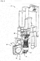
- storage container 140 that stores components in a bulk state is arranged in component depositing section 138.
- the side walls at the front side and rear side in fig. 5 are formed from a relatively thin and transparent resin plate.
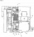
- Disc 144 on which multiple magnets 142, in this case, twelve magnets 142 are supported, is arranged on the outside of the side wall at the rear side of storage container 140. That is, multiple magnets 142 are arranged in a circle along the side wall separated by a set angular pitch.
- Disc 144 is rotated by rotating device 146, such that the multiple magnets 142 are revolved around the circle on which they are arranged. That is, rotating device 146 functions as a magnet rotating device.
- Rotating device 146 includes a stepping motor as a drive source, and control of the stepping motor is performed by controller 148, which is a control device based around a computer.
- component storage space 150 with a sloping bottom is formed in storage container 140, and components P are supplied to component storage space 150 from supply opening 150 that is provided at an upper section, and are stored in a bulk state inside component storage space 150. That is, components are stored so as to gather in groups inside component storage space 150.
- disc 144 and multiple magnets 142 are arranged as shown by the two-dotted broken lines; disc 144 causes the multiple magnets 142 to revolve in a forward direction (direction of white arrow in figs. 5 and 6 ), by being rotated in a forward direction, that is, by forward rotation.
- Depositing path 154 is integrated with component storage space 150 inside storage container 140 and extends in a vertical direction, and components P are moved above depositing path 154 by magnets 142.
- Stopping wall 156 is provided above depositing path 154 to demarcate a portion of component storage space 150, and conveyed components P are stopped by stopping wall 156, such that when the pulling by magnet 142 no longer has an effect, the component P falls due its own weight into depositing path 154.
- Case 70 is positioned such that depositing opening 77 faces the lower end of depositing path 154, and components P that follow into depositing path 154 are deposited into case 70 from the lower end of depositing path 154.
- shutter 158 is provided at a lower section of depositing path 154 to prevent components P being ejected at a time except when components P are being deposited in case 70.
- a sensor for detecting the amount of stored components is provided in case 70, and when the sensor detects that there is a specified quantity of components P stored in case 70, controller 148 stops rotation of disc 144 so as to stop depositing of components P.
- controller 148 stops rotation of disc 144 so as to stop depositing of components P.
- the conveyed components P may drop into depositing path 154, and the dropped components P may cause a blockage at depositing path 154.
- shutter 158 is closed, because components P accumulate on shutter 158, it is more likely that a blockage of depositing path 154 will occur.
- the multiple magnets 142 are stopped such that magnets 142 currently pulling components are not positioned above depositing path 154.
- the position of the magnets shown in fig. 6 is an example of a position at which magnets 142 are not positioned above depositing path 154.
- the multiple magnets 142 may be stopped after being reverse-rotated by at least a set angle.
- forward rotation and reverse rotation may then be repeated.
- forward and reverse rotation may then be repeated.
- components being conveyed by magnet 142 above a component group to drop from the magnet onto the component group in component storage space 150.
- components P being conveyed above a component group to drop onto the component group by stopping after having performed reverse-rotation by at least the set angular pitch at at least a speed at which the pulling of the components P being conveyed above the component group by the multiple magnets 142 is released, regardless of the final stopping position of the multiple magnets 142.
- By causing the components P to drop it is possible to prevent blockages caused by components P falling into depositing path 154 after depositing of components is complete.
Landscapes
- Engineering & Computer Science (AREA)
- Manufacturing & Machinery (AREA)
- Microelectronics & Electronic Packaging (AREA)
- Mechanical Engineering (AREA)
- Supply And Installment Of Electrical Components (AREA)
- Feeding Of Articles To Conveyors (AREA)
Applications Claiming Priority (1)
| Application Number | Priority Date | Filing Date | Title |
|---|---|---|---|
| PCT/JP2015/084258 WO2017098551A1 (ja) | 2015-12-07 | 2015-12-07 | 部品投入装置 |
Publications (3)
| Publication Number | Publication Date |
|---|---|
| EP3389350A1 true EP3389350A1 (de) | 2018-10-17 |
| EP3389350A4 EP3389350A4 (de) | 2019-01-02 |
| EP3389350B1 EP3389350B1 (de) | 2021-01-27 |
Family
ID=59013822
Family Applications (1)
| Application Number | Title | Priority Date | Filing Date |
|---|---|---|---|
| EP15910168.2A Active EP3389350B1 (de) | 2015-12-07 | 2015-12-07 | Gerät zur komponentenablage |
Country Status (5)
| Country | Link |
|---|---|
| US (1) | US10531600B2 (de) |
| EP (1) | EP3389350B1 (de) |
| JP (1) | JP6739446B2 (de) |
| CN (1) | CN108370658B (de) |
| WO (1) | WO2017098551A1 (de) |
Family Cites Families (7)
| Publication number | Priority date | Publication date | Assignee | Title |
|---|---|---|---|---|
| JP4533967B2 (ja) * | 2008-12-12 | 2010-09-01 | 太陽誘電株式会社 | バルクフィーダ |
| JP5917683B2 (ja) * | 2012-03-28 | 2016-05-18 | 富士機械製造株式会社 | 電子部品装着機 |
| EP2852270B1 (de) * | 2012-05-15 | 2020-11-25 | FUJI Corporation | Maschine zur montage von elektronischen bauteilen |
| JP6058657B2 (ja) * | 2012-06-18 | 2017-01-11 | 富士機械製造株式会社 | バルクフィーダ |
| US10080320B2 (en) | 2012-09-20 | 2018-09-18 | Fuji Corporation | Bulk component supply system and bulk component replenishment method |
| JPWO2014192168A1 (ja) * | 2013-05-27 | 2017-02-23 | 富士機械製造株式会社 | 電子回路部品実装システム |
| JP6308763B2 (ja) * | 2013-12-05 | 2018-04-11 | 富士機械製造株式会社 | バルク部品供給システムおよびバルク部品補給方法 |
-
2015
- 2015-12-07 EP EP15910168.2A patent/EP3389350B1/de active Active
- 2015-12-07 JP JP2017554673A patent/JP6739446B2/ja active Active
- 2015-12-07 US US15/778,276 patent/US10531600B2/en active Active
- 2015-12-07 WO PCT/JP2015/084258 patent/WO2017098551A1/ja not_active Ceased
- 2015-12-07 CN CN201580085122.8A patent/CN108370658B/zh active Active
Also Published As
| Publication number | Publication date |
|---|---|
| JPWO2017098551A1 (ja) | 2018-10-18 |
| CN108370658A (zh) | 2018-08-03 |
| US10531600B2 (en) | 2020-01-07 |
| EP3389350A4 (de) | 2019-01-02 |
| WO2017098551A1 (ja) | 2017-06-15 |
| JP6739446B2 (ja) | 2020-08-12 |
| EP3389350B1 (de) | 2021-01-27 |
| US20180343776A1 (en) | 2018-11-29 |
| CN108370658B (zh) | 2019-09-03 |
Similar Documents
| Publication | Publication Date | Title |
|---|---|---|
| US11039558B2 (en) | Component mounting line production management system and production management method | |
| US11134601B2 (en) | System for managing component mounting line | |
| US12304732B2 (en) | Automatic picking machine for filling a transport container | |
| EP2833708A1 (de) | Schüttgutzuführvorrichtung und montagevorrichtung für elektronische komponente | |
| EP3389350B1 (de) | Gerät zur komponentenablage | |
| EP3468329B1 (de) | Komponentenzuführvorrichtung | |
| JP6335526B2 (ja) | ブラシ用のバッファ | |
| US6152281A (en) | Magnetic bulk feeder for electronic components | |
| CN109502351A (zh) | 宠物餐盘自动投放及自动回收设备 | |
| EP2471373A1 (de) | Vorrichtung zur Positionierung von Garnelen | |
| EP1727413A1 (de) | Ein Verfahren zum Zuführen eines Bauteils und eine Vorrichtung zum Zuführen eines Bauteils | |
| CN208067739U (zh) | 一种指甲剪用的自动组装机 | |
| CN110615224A (zh) | 分拣货架 | |
| CN214933707U (zh) | 一种自动分药机 | |
| CN211544036U (zh) | 筷子插片机 | |
| WO2019196391A1 (zh) | 伸缩车装置及储物柜 | |
| CN211140483U (zh) | 分拣货架 | |
| CN110349896B (zh) | 一种具有调节功能的芯片拾取系统 | |
| CN222655207U (zh) | 一种可以调整出食物位置的鸟类观察摄像头装置 | |
| WO2015029216A1 (ja) | 部品実装機 | |
| CN209259116U (zh) | 一种自动上下料设备 | |
| CN109533816A (zh) | 一种振动盘 | |
| JP6769787B2 (ja) | バルクフィーダカセット供給装置 | |
| CN208814118U (zh) | 分料机构及具有其的螺母供料系统 | |
| CN106816607B (zh) | 一种纽扣电池自动装盘机构 |
Legal Events
| Date | Code | Title | Description |
|---|---|---|---|
| STAA | Information on the status of an ep patent application or granted ep patent |
Free format text: STATUS: THE INTERNATIONAL PUBLICATION HAS BEEN MADE |
|
| PUAI | Public reference made under article 153(3) epc to a published international application that has entered the european phase |
Free format text: ORIGINAL CODE: 0009012 |
|
| STAA | Information on the status of an ep patent application or granted ep patent |
Free format text: STATUS: REQUEST FOR EXAMINATION WAS MADE |
|
| 17P | Request for examination filed |
Effective date: 20180606 |
|
| AK | Designated contracting states |
Kind code of ref document: A1 Designated state(s): AL AT BE BG CH CY CZ DE DK EE ES FI FR GB GR HR HU IE IS IT LI LT LU LV MC MK MT NL NO PL PT RO RS SE SI SK SM TR |
|
| AX | Request for extension of the european patent |
Extension state: BA ME |
|
| RIC1 | Information provided on ipc code assigned before grant |
Ipc: H05K 13/02 20060101AFI20181123BHEP Ipc: H05K 13/04 20060101ALI20181123BHEP |
|
| A4 | Supplementary search report drawn up and despatched |
Effective date: 20181129 |
|
| RIN1 | Information on inventor provided before grant (corrected) |
Inventor name: WATANABE, MASAHIRO |
|
| DAV | Request for validation of the european patent (deleted) | ||
| DAX | Request for extension of the european patent (deleted) | ||
| GRAP | Despatch of communication of intention to grant a patent |
Free format text: ORIGINAL CODE: EPIDOSNIGR1 |
|
| STAA | Information on the status of an ep patent application or granted ep patent |
Free format text: STATUS: GRANT OF PATENT IS INTENDED |
|
| INTG | Intention to grant announced |
Effective date: 20201005 |
|
| GRAS | Grant fee paid |
Free format text: ORIGINAL CODE: EPIDOSNIGR3 |
|
| GRAA | (expected) grant |
Free format text: ORIGINAL CODE: 0009210 |
|
| STAA | Information on the status of an ep patent application or granted ep patent |
Free format text: STATUS: THE PATENT HAS BEEN GRANTED |
|
| AK | Designated contracting states |
Kind code of ref document: B1 Designated state(s): AL AT BE BG CH CY CZ DE DK EE ES FI FR GB GR HR HU IE IS IT LI LT LU LV MC MK MT NL NO PL PT RO RS SE SI SK SM TR |
|
| REG | Reference to a national code |
Ref country code: GB Ref legal event code: FG4D |
|
| REG | Reference to a national code |
Ref country code: CH Ref legal event code: EP |
|
| REG | Reference to a national code |
Ref country code: AT Ref legal event code: REF Ref document number: 1359500 Country of ref document: AT Kind code of ref document: T Effective date: 20210215 |
|
| REG | Reference to a national code |
Ref country code: IE Ref legal event code: FG4D |
|
| REG | Reference to a national code |
Ref country code: DE Ref legal event code: R096 Ref document number: 602015065382 Country of ref document: DE |
|
| REG | Reference to a national code |
Ref country code: NL Ref legal event code: MP Effective date: 20210127 |
|
| REG | Reference to a national code |
Ref country code: LT Ref legal event code: MG9D |
|
| REG | Reference to a national code |
Ref country code: AT Ref legal event code: MK05 Ref document number: 1359500 Country of ref document: AT Kind code of ref document: T Effective date: 20210127 |
|
| PG25 | Lapsed in a contracting state [announced via postgrant information from national office to epo] |
Ref country code: PT Free format text: LAPSE BECAUSE OF FAILURE TO SUBMIT A TRANSLATION OF THE DESCRIPTION OR TO PAY THE FEE WITHIN THE PRESCRIBED TIME-LIMIT Effective date: 20210527 Ref country code: NO Free format text: LAPSE BECAUSE OF FAILURE TO SUBMIT A TRANSLATION OF THE DESCRIPTION OR TO PAY THE FEE WITHIN THE PRESCRIBED TIME-LIMIT Effective date: 20210427 Ref country code: BG Free format text: LAPSE BECAUSE OF FAILURE TO SUBMIT A TRANSLATION OF THE DESCRIPTION OR TO PAY THE FEE WITHIN THE PRESCRIBED TIME-LIMIT Effective date: 20210427 Ref country code: FI Free format text: LAPSE BECAUSE OF FAILURE TO SUBMIT A TRANSLATION OF THE DESCRIPTION OR TO PAY THE FEE WITHIN THE PRESCRIBED TIME-LIMIT Effective date: 20210127 Ref country code: GR Free format text: LAPSE BECAUSE OF FAILURE TO SUBMIT A TRANSLATION OF THE DESCRIPTION OR TO PAY THE FEE WITHIN THE PRESCRIBED TIME-LIMIT Effective date: 20210428 Ref country code: HR Free format text: LAPSE BECAUSE OF FAILURE TO SUBMIT A TRANSLATION OF THE DESCRIPTION OR TO PAY THE FEE WITHIN THE PRESCRIBED TIME-LIMIT Effective date: 20210127 Ref country code: LT Free format text: LAPSE BECAUSE OF FAILURE TO SUBMIT A TRANSLATION OF THE DESCRIPTION OR TO PAY THE FEE WITHIN THE PRESCRIBED TIME-LIMIT Effective date: 20210127 |
|
| PG25 | Lapsed in a contracting state [announced via postgrant information from national office to epo] |
Ref country code: AT Free format text: LAPSE BECAUSE OF FAILURE TO SUBMIT A TRANSLATION OF THE DESCRIPTION OR TO PAY THE FEE WITHIN THE PRESCRIBED TIME-LIMIT Effective date: 20210127 Ref country code: RS Free format text: LAPSE BECAUSE OF FAILURE TO SUBMIT A TRANSLATION OF THE DESCRIPTION OR TO PAY THE FEE WITHIN THE PRESCRIBED TIME-LIMIT Effective date: 20210127 Ref country code: LV Free format text: LAPSE BECAUSE OF FAILURE TO SUBMIT A TRANSLATION OF THE DESCRIPTION OR TO PAY THE FEE WITHIN THE PRESCRIBED TIME-LIMIT Effective date: 20210127 Ref country code: PL Free format text: LAPSE BECAUSE OF FAILURE TO SUBMIT A TRANSLATION OF THE DESCRIPTION OR TO PAY THE FEE WITHIN THE PRESCRIBED TIME-LIMIT Effective date: 20210127 Ref country code: SE Free format text: LAPSE BECAUSE OF FAILURE TO SUBMIT A TRANSLATION OF THE DESCRIPTION OR TO PAY THE FEE WITHIN THE PRESCRIBED TIME-LIMIT Effective date: 20210127 |
|
| PG25 | Lapsed in a contracting state [announced via postgrant information from national office to epo] |
Ref country code: IS Free format text: LAPSE BECAUSE OF FAILURE TO SUBMIT A TRANSLATION OF THE DESCRIPTION OR TO PAY THE FEE WITHIN THE PRESCRIBED TIME-LIMIT Effective date: 20210527 |
|
| REG | Reference to a national code |
Ref country code: DE Ref legal event code: R097 Ref document number: 602015065382 Country of ref document: DE |
|
| PG25 | Lapsed in a contracting state [announced via postgrant information from national office to epo] |
Ref country code: EE Free format text: LAPSE BECAUSE OF FAILURE TO SUBMIT A TRANSLATION OF THE DESCRIPTION OR TO PAY THE FEE WITHIN THE PRESCRIBED TIME-LIMIT Effective date: 20210127 Ref country code: CZ Free format text: LAPSE BECAUSE OF FAILURE TO SUBMIT A TRANSLATION OF THE DESCRIPTION OR TO PAY THE FEE WITHIN THE PRESCRIBED TIME-LIMIT Effective date: 20210127 Ref country code: SM Free format text: LAPSE BECAUSE OF FAILURE TO SUBMIT A TRANSLATION OF THE DESCRIPTION OR TO PAY THE FEE WITHIN THE PRESCRIBED TIME-LIMIT Effective date: 20210127 |
|
| PG25 | Lapsed in a contracting state [announced via postgrant information from national office to epo] |
Ref country code: SK Free format text: LAPSE BECAUSE OF FAILURE TO SUBMIT A TRANSLATION OF THE DESCRIPTION OR TO PAY THE FEE WITHIN THE PRESCRIBED TIME-LIMIT Effective date: 20210127 Ref country code: RO Free format text: LAPSE BECAUSE OF FAILURE TO SUBMIT A TRANSLATION OF THE DESCRIPTION OR TO PAY THE FEE WITHIN THE PRESCRIBED TIME-LIMIT Effective date: 20210127 Ref country code: DK Free format text: LAPSE BECAUSE OF FAILURE TO SUBMIT A TRANSLATION OF THE DESCRIPTION OR TO PAY THE FEE WITHIN THE PRESCRIBED TIME-LIMIT Effective date: 20210127 |
|
| PLBE | No opposition filed within time limit |
Free format text: ORIGINAL CODE: 0009261 |
|
| STAA | Information on the status of an ep patent application or granted ep patent |
Free format text: STATUS: NO OPPOSITION FILED WITHIN TIME LIMIT |
|
| 26N | No opposition filed |
Effective date: 20211028 |
|
| PG25 | Lapsed in a contracting state [announced via postgrant information from national office to epo] |
Ref country code: AL Free format text: LAPSE BECAUSE OF FAILURE TO SUBMIT A TRANSLATION OF THE DESCRIPTION OR TO PAY THE FEE WITHIN THE PRESCRIBED TIME-LIMIT Effective date: 20210127 Ref country code: ES Free format text: LAPSE BECAUSE OF FAILURE TO SUBMIT A TRANSLATION OF THE DESCRIPTION OR TO PAY THE FEE WITHIN THE PRESCRIBED TIME-LIMIT Effective date: 20210127 |
|
| PG25 | Lapsed in a contracting state [announced via postgrant information from national office to epo] |
Ref country code: SI Free format text: LAPSE BECAUSE OF FAILURE TO SUBMIT A TRANSLATION OF THE DESCRIPTION OR TO PAY THE FEE WITHIN THE PRESCRIBED TIME-LIMIT Effective date: 20210127 |
|
| PG25 | Lapsed in a contracting state [announced via postgrant information from national office to epo] |
Ref country code: IT Free format text: LAPSE BECAUSE OF FAILURE TO SUBMIT A TRANSLATION OF THE DESCRIPTION OR TO PAY THE FEE WITHIN THE PRESCRIBED TIME-LIMIT Effective date: 20210127 |
|
| PG25 | Lapsed in a contracting state [announced via postgrant information from national office to epo] |
Ref country code: IS Free format text: LAPSE BECAUSE OF FAILURE TO SUBMIT A TRANSLATION OF THE DESCRIPTION OR TO PAY THE FEE WITHIN THE PRESCRIBED TIME-LIMIT Effective date: 20210527 |
|
| PG25 | Lapsed in a contracting state [announced via postgrant information from national office to epo] |
Ref country code: MC Free format text: LAPSE BECAUSE OF FAILURE TO SUBMIT A TRANSLATION OF THE DESCRIPTION OR TO PAY THE FEE WITHIN THE PRESCRIBED TIME-LIMIT Effective date: 20210127 |
|
| REG | Reference to a national code |
Ref country code: CH Ref legal event code: PL |
|
| GBPC | Gb: european patent ceased through non-payment of renewal fee |
Effective date: 20211207 |
|
| REG | Reference to a national code |
Ref country code: BE Ref legal event code: MM Effective date: 20211231 |
|
| PG25 | Lapsed in a contracting state [announced via postgrant information from national office to epo] |
Ref country code: LU Free format text: LAPSE BECAUSE OF NON-PAYMENT OF DUE FEES Effective date: 20211207 Ref country code: IE Free format text: LAPSE BECAUSE OF NON-PAYMENT OF DUE FEES Effective date: 20211207 Ref country code: GB Free format text: LAPSE BECAUSE OF NON-PAYMENT OF DUE FEES Effective date: 20211207 |
|
| PG25 | Lapsed in a contracting state [announced via postgrant information from national office to epo] |
Ref country code: FR Free format text: LAPSE BECAUSE OF NON-PAYMENT OF DUE FEES Effective date: 20211231 Ref country code: BE Free format text: LAPSE BECAUSE OF NON-PAYMENT OF DUE FEES Effective date: 20211231 |
|
| PG25 | Lapsed in a contracting state [announced via postgrant information from national office to epo] |
Ref country code: LI Free format text: LAPSE BECAUSE OF NON-PAYMENT OF DUE FEES Effective date: 20211231 Ref country code: CH Free format text: LAPSE BECAUSE OF NON-PAYMENT OF DUE FEES Effective date: 20211231 |
|
| PG25 | Lapsed in a contracting state [announced via postgrant information from national office to epo] |
Ref country code: HU Free format text: LAPSE BECAUSE OF FAILURE TO SUBMIT A TRANSLATION OF THE DESCRIPTION OR TO PAY THE FEE WITHIN THE PRESCRIBED TIME-LIMIT; INVALID AB INITIO Effective date: 20151207 |
|
| P01 | Opt-out of the competence of the unified patent court (upc) registered |
Effective date: 20230328 |
|
| PG25 | Lapsed in a contracting state [announced via postgrant information from national office to epo] |
Ref country code: NL Free format text: LAPSE BECAUSE OF NON-PAYMENT OF DUE FEES Effective date: 20210127 Ref country code: CY Free format text: LAPSE BECAUSE OF FAILURE TO SUBMIT A TRANSLATION OF THE DESCRIPTION OR TO PAY THE FEE WITHIN THE PRESCRIBED TIME-LIMIT Effective date: 20210127 |
|
| PG25 | Lapsed in a contracting state [announced via postgrant information from national office to epo] |
Ref country code: MK Free format text: LAPSE BECAUSE OF FAILURE TO SUBMIT A TRANSLATION OF THE DESCRIPTION OR TO PAY THE FEE WITHIN THE PRESCRIBED TIME-LIMIT Effective date: 20210127 |
|
| PG25 | Lapsed in a contracting state [announced via postgrant information from national office to epo] |
Ref country code: TR Free format text: LAPSE BECAUSE OF FAILURE TO SUBMIT A TRANSLATION OF THE DESCRIPTION OR TO PAY THE FEE WITHIN THE PRESCRIBED TIME-LIMIT Effective date: 20210127 |
|
| PG25 | Lapsed in a contracting state [announced via postgrant information from national office to epo] |
Ref country code: MT Free format text: LAPSE BECAUSE OF FAILURE TO SUBMIT A TRANSLATION OF THE DESCRIPTION OR TO PAY THE FEE WITHIN THE PRESCRIBED TIME-LIMIT Effective date: 20210127 |
|
| PGFP | Annual fee paid to national office [announced via postgrant information from national office to epo] |
Ref country code: DE Payment date: 20251028 Year of fee payment: 11 |